US7714797B2 - Phased array antenna - Google Patents
Phased array antennaDownload PDFInfo
- Publication number
- US7714797B2 US7714797B2US10/585,098US58509806DUS7714797B2US 7714797 B2US7714797 B2US 7714797B2US 58509806 DUS58509806 DUS 58509806DUS 7714797 B2US7714797 B2US 7714797B2
- Authority
- US
- United States
- Prior art keywords
- antenna
- panel
- base member
- panels
- deployed
- Prior art date
- Legal status (The legal status is an assumption and is not a legal conclusion. Google has not performed a legal analysis and makes no representation as to the accuracy of the status listed.)
- Active, expires
Links
- 238000003491arrayMethods0.000claimsdescription19
- 230000001419dependent effectEffects0.000claimsdescription2
- 238000004891communicationMethods0.000description6
- 238000013461designMethods0.000description6
- 238000010276constructionMethods0.000description5
- 230000008901benefitEffects0.000description3
- 239000004020conductorSubstances0.000description3
- 230000008878couplingEffects0.000description3
- 238000010168coupling processMethods0.000description3
- 238000005859coupling reactionMethods0.000description3
- 238000000034methodMethods0.000description3
- 230000005540biological transmissionEffects0.000description2
- 230000000694effectsEffects0.000description2
- 238000005516engineering processMethods0.000description2
- 230000010354integrationEffects0.000description2
- 230000005855radiationEffects0.000description2
- 230000035945sensitivityEffects0.000description2
- 238000012360testing methodMethods0.000description2
- 230000004308accommodationEffects0.000description1
- 230000000712assemblyEffects0.000description1
- 238000000429assemblyMethods0.000description1
- 238000006243chemical reactionMethods0.000description1
- 238000009826distributionMethods0.000description1
- 230000009977dual effectEffects0.000description1
- 238000012986modificationMethods0.000description1
- 230000004048modificationEffects0.000description1
- 238000012545processingMethods0.000description1
- 230000009467reductionEffects0.000description1
- 230000008054signal transmissionEffects0.000description1
- 230000003068static effectEffects0.000description1
Images


Classifications
- H—ELECTRICITY
- H01—ELECTRIC ELEMENTS
- H01Q—ANTENNAS, i.e. RADIO AERIALS
- H01Q1/00—Details of, or arrangements associated with, antennas
- H01Q1/27—Adaptation for use in or on movable bodies
- H01Q1/28—Adaptation for use in or on aircraft, missiles, satellites, or balloons
- H01Q1/288—Satellite antennas
- B—PERFORMING OPERATIONS; TRANSPORTING
- B64—AIRCRAFT; AVIATION; COSMONAUTICS
- B64G—COSMONAUTICS; VEHICLES OR EQUIPMENT THEREFOR
- B64G1/00—Cosmonautic vehicles
- B64G1/22—Parts of, or equipment specially adapted for fitting in or to, cosmonautic vehicles
- B64G1/222—Parts of, or equipment specially adapted for fitting in or to, cosmonautic vehicles for deploying structures between a stowed and deployed state
- B64G1/2221—Parts of, or equipment specially adapted for fitting in or to, cosmonautic vehicles for deploying structures between a stowed and deployed state characterised by the manner of deployment
- B64G1/2222—Folding
- B64G1/2224—Folding about multiple axes
- B—PERFORMING OPERATIONS; TRANSPORTING
- B64—AIRCRAFT; AVIATION; COSMONAUTICS
- B64G—COSMONAUTICS; VEHICLES OR EQUIPMENT THEREFOR
- B64G1/00—Cosmonautic vehicles
- B64G1/22—Parts of, or equipment specially adapted for fitting in or to, cosmonautic vehicles
- B64G1/66—Arrangements or adaptations of apparatus or instruments, not otherwise provided for
- H—ELECTRICITY
- H01—ELECTRIC ELEMENTS
- H01Q—ANTENNAS, i.e. RADIO AERIALS
- H01Q1/00—Details of, or arrangements associated with, antennas
- H01Q1/08—Means for collapsing antennas or parts thereof
- H01Q1/084—Pivotable antennas
- H—ELECTRICITY
- H01—ELECTRIC ELEMENTS
- H01Q—ANTENNAS, i.e. RADIO AERIALS
- H01Q1/00—Details of, or arrangements associated with, antennas
- H01Q1/12—Supports; Mounting means
- H01Q1/1207—Supports; Mounting means for fastening a rigid aerial element
- H01Q1/1228—Supports; Mounting means for fastening a rigid aerial element on a boom
- H—ELECTRICITY
- H01—ELECTRIC ELEMENTS
- H01Q—ANTENNAS, i.e. RADIO AERIALS
- H01Q1/00—Details of, or arrangements associated with, antennas
- H01Q1/42—Housings not intimately mechanically associated with radiating elements, e.g. radome
- H01Q1/422—Housings not intimately mechanically associated with radiating elements, e.g. radome comprising two or more layers of dielectric material
- H—ELECTRICITY
- H01—ELECTRIC ELEMENTS
- H01Q—ANTENNAS, i.e. RADIO AERIALS
- H01Q21/00—Antenna arrays or systems
- H01Q21/06—Arrays of individually energised antenna units similarly polarised and spaced apart
- H01Q21/061—Two dimensional planar arrays
- H01Q21/065—Patch antenna array
- H—ELECTRICITY
- H04—ELECTRIC COMMUNICATION TECHNIQUE
- H04B—TRANSMISSION
- H04B7/00—Radio transmission systems, i.e. using radiation field
- H04B7/14—Relay systems
- H04B7/15—Active relay systems
- H04B7/185—Space-based or airborne stations; Stations for satellite systems
- H04B7/1851—Systems using a satellite or space-based relay
- H04B7/18515—Transmission equipment in satellites or space-based relays
- B—PERFORMING OPERATIONS; TRANSPORTING
- B64—AIRCRAFT; AVIATION; COSMONAUTICS
- B64G—COSMONAUTICS; VEHICLES OR EQUIPMENT THEREFOR
- B64G1/00—Cosmonautic vehicles
- B64G1/10—Artificial satellites; Systems of such satellites; Interplanetary vehicles
- Y—GENERAL TAGGING OF NEW TECHNOLOGICAL DEVELOPMENTS; GENERAL TAGGING OF CROSS-SECTIONAL TECHNOLOGIES SPANNING OVER SEVERAL SECTIONS OF THE IPC; TECHNICAL SUBJECTS COVERED BY FORMER USPC CROSS-REFERENCE ART COLLECTIONS [XRACs] AND DIGESTS
- Y10—TECHNICAL SUBJECTS COVERED BY FORMER USPC
- Y10S—TECHNICAL SUBJECTS COVERED BY FORMER USPC CROSS-REFERENCE ART COLLECTIONS [XRACs] AND DIGESTS
- Y10S343/00—Communications: radio wave antennas
- Y10S343/02—Satellite-mounted antenna
Definitions
- This inventionrelates to a phased array antenna, particularly though not exclusively, for use with telecommunications satellites.
- Antenna structures onboard telecommunication satellitescommonly include rigid reflectors, up to around 2.5 meters diameter, or more complex structures, for example unfurlable wire mesh reflectors up to 9 meters across.
- the arraymay operate as a transmit only, a receive only, or as a combined transmit/receive antenna.
- Phased array antennasare in general use as compact, stationary structures for the flexible direction of electromagnetic energy for multi-beam, fast reaction tracking radar and telecommunications antennas. They are mechanically static but which can be electronically reconfigured to transmit or receive signals over a defined coverage region.
- ground based satellite terminalsuse phased arrays for tracking and communicating with satellites in low earth orbit, and flat plate phased array antennas are used for reception of satellite direct to home TV broadcasts.
- Phased array antennasare used as an alternative to conventional reflector antennas onboard communications spacecraft.
- Examplesinclude the Boeing Gapfiller military satellite, which uses fixed (non-deployable) separate receive and transmit X-band arrays (http://www.boeing.com/defense-space/space/bss/factsheets/702/wgs/wgs factsheet.html) and the Boeing Spaceway commercial satellite system, which uses which uses fixed Ka band phased arrays (http://www.boeing.com/ids/allsystemsgo/issues/vol1/num3/story06.html). These antennas are of relatively small aperture and are fixed structures.
- a deployable planar phased array antenna system for a telecommunications satelliteis of a large aperture design and is deployed after the satellite is on-station in space.
- the larger aperturefacilitates the generation of smaller diameter spot beams on the earth's surface, enabling system capacity to be increased through higher orders of frequency re-use.
- the smaller beam sizealso corresponds with an increase in the satellite transmitter EIRP (Effective Isotropic Radiated Power) and receiver sensitivity permitting operation with small, low power, lower cost terminals.
- the present inventionprovides in a first aspect a phased array antenna, deployable from a retracted condition to a deployed condition, comprising a base member having, at least in part, a polygonal cross-sectional form defined by a plurality of edge regions, and a plurality of antenna panels, each antenna panel being connected, by a respective hinge means, to a respective one of said edge regions of said base member, such that, in said retracted condition, two or more of the antenna panels are stacked one on top of the other on the base member, and the hinge means being such that the antenna panels can be hinged sequentially one after the other from the stack to a position in which each panel is adjacent a respective base edge region to provide said deployed condition wherein the phased array antenna provides an extended area.
- the top surface of the base memberpreferably provides a further antenna panel.
- the panels and base membermay preferably present a flat two dimensional surface, otherwise undesirable phase increments may arise between radiator elements.
- the upper surfaces of the panelsmay be aligned with the upper surface of the base member in the deployed condition; minor steps or discontinuities may however be corrected by signal processing.
- the polygonal cross-sectional shapemay be of any shape, but is preferably regular. It may be triangular, rectangular, pentagonal, etc, but in one preferred form, from electrical considerations of antenna design, is hexagonal, with six sides.
- the antenna panelsmay have the same cross-section as the base member, and are stacked on top of the base member so as to present a uniform cross-section in a lengthwise direction. This is particularly desirable where the antenna forms part of a telecommunications satellite that has to be launched through the earth's atmosphere.
- the panelsmay however have different cross-sections if necessary.
- the outer edges of each panelhave a castellated form, so that sub-arrays of radiator elements may have an optimum configuration.
- the panelsare shaped and dimensioned that in the deployed condition, edges of the panel are coterminous with the respective base edge region. This permits electrical continuity of the antenna, and permits electrical connections to be made across the edges. Edges of each panel extending from the base edge region may be positioned next to the corresponding edge of an adjacent panel; in this way, the area of the antenna as deployed is closed.
- an additional set of antenna panelsmay be provided, each additional antenna panel being hinged to one of the above first mentioned antenna panels, so that when the antenna panels are deployed from the retracted condition, firstly a first antenna panel is moved to the deployed position, and subsequently the additional antenna panel is pivoted from a position lying on top of the first panel to a deployed position.
- an antenna with a very large areamay be provided.
- the antennaIn the deployed position, the antenna provides preferably, roughly a circular closed area, so that the antenna provides an optimally large aperture.
- each antenna panelis coupled to the base member by means of a hinge means having a pivot point that is positioned relative to the position of the antenna panel in the retracted stack of antenna elements, so that the antenna panel upon rotation of the hinge to the deployed condition, makes a 180° rotation and a translatory movement to the plane at the top of the base member in the fully deployed position.
- the hingeis preferably of a “back-flap” construction, with a support frame extending from the pivot point over the underside of the panel member; in this way, it does not interfere with the electrical characteristics of the antenna.
- the pivot of the hingeis preferably formed as an elongate sleeve and pin arrangement, to ensure that the pivot point remains accurately positioned throughout.
- the stack of antenna panelsmay comprise all of the panels to one side of the base member. Alternatively one or more antenna panels may be disposed when retracted on the opposite side of the base member. This may be the case where the antenna is intended for a telecommunications satellite, where the base member is coupled to a service module by means of a boom member, in order to avoid collision with the boom member.
- the antennais disposed on top of the satellite service module during the launch phase, but when the satellite is on-station, then the antenna is rotated through 90°, in its retracted condition, by means of the boom member, to a position where the antenna is deployed. In this condition, the whole service module, including the deployed solar arrays, is able to rotate relative to the antenna (once every 24 hrs).
- Such an arrangementis known and is for example described in Communications Satellites, The Technology of Space Communications, Published 1987 by Heinemann, Author J. L. Blonstein, page 147.
- the antennapoints at the earth while the service module solar arrays point at the sun.
- the solar arraysare fixed to the service module and do not rotate relative to the service module.
- the base unithas to rotate 90° relative to the boom arm connecting it to the service module before the stowed panels can be deployed.
- the boom armblocks the deployment of one panel from the rear of the base unit.
- the simplest arrangementis to have the “missing” panel fold directly from the front face of the base unit. More panels could be stacked on the front face of the base unit but the backflap hinge design means that mechanical hinge parts (possibly electrically conductive) would project in front of the antenna active surface, thereby disrupting the radiation pattern. It is the projection of mechanical parts in front of the antenna aperture that this invention avoids.
- the inventionprovides a telecommunications satellite comprising a service module and a phased array antenna coupled to the service module by means of a boom member, the service module including solar panels, and the phased array antenna being deployable from a retracted condition to a deployed condition, wherein in the retracted condition, the antenna is positioned on top of the service module, and the boom member including rotatable means so that the antenna, when deployed, can be rotated relative to the service module, and the antenna comprising a plurality of antenna panels, such that, in said retracted condition, two or more of the antenna panels are stacked one on top of the other, wherein for deployment, the antenna is firstly moved by means of the boom member to a position away from the service module, and then the antenna panels are moved to a deployed condition wherein the phased array antenna provides an extended area.
- the upper surface of the paneltogether with the top surface of the base member, provide an array of radiator elements of the phased array antenna.
- the radiator elementsmay be arranged in subarrays having a certain geometric shape.
- the outer edges of each panelhave a castellated form, so that sub-arrays of radiator elements may have an optimum hexagonal configuration.
- the sub arraysmay extend over the edges of the panels onto the base member and adjacent panels as required.
- each panelhas appropriate electrical conductors and components for coupling the radiator elements.
- Such conductor tracksare coupled to the base member, across adjoining edges, through appropriately designed electrical contacts in the deployed condition.
- the adjacent edges of each panel member and the base membermay have protruding electrical contacts that are spring loaded, or of cantilever design for example, so that they make contact with some spring force to maintain electrical contact. Alternatively they may make a snap fit connection.
- simple proximity (capacitive) connectionsmay be sufficient at Ka band frequencies.
- the advantage with the hinge construction of the present inventionis that it confers great mechanical rigidity to the positioning of the deployed panel relative to the base unit. This facilitates a number of multi-pin connector schemes because of the precision with which the male and female parts can be aligned.
- FIGS. 1A , 1 B and 1 Care perspective views of a first embodiment of the invention comprising a spacecraft with a deployable antenna in a retracted condition, and with solar panels in furled and unfurled conditions;
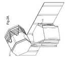
- FIGS. 2A to 2Gare perspective views showing sequential steps in the deployment of the antenna
- FIGS. 3A to 3Care perspective views of a second embodiment of the invention with FIG. 3A showing the antenna of the telecommunications satellite in a retracted position, FIG. 3B showing the antenna in a raised position from the body of the satellite, and FIG. 3C showing the fully deployed antenna array;
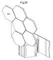
- FIG. 4is a plan view of the deployed array showing the antenna panels forming a roughly circular closed surface
- FIG. 5shows constructional details of each antenna element
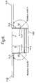
- FIG. 6shows, in schematic form, a cross-sectional view of a central base unit with antenna panels connected to the central unit by hinges.
- a phased array antennacomprises a number of antenna panels, which are hinged together and folded when stowed prior to deployment. On deployment the array is unfolded to form a continuous large planar antenna aperture.
- Each antenna panelcomprises a multiplicity of active antennas. The composition of each of these active antennas depends on the functioning of the array, transmit/receive, receive only, transmit only.
- a first embodimentcomprises a telecommunications satellite having a service module body 2 and a deployable antenna 4 that is positioned in a retracted condition coaxial with the body 2 .
- Both the body and the antennaare of hexagonal cross section.
- the antennais mounted to the body by means of a boom 6 .
- Boom 6is coupled to antenna 4 through a swivel joint 8 that permits rotation in two planes, as will become apparent.
- Stay members 10are provided for holding the antenna in the position shown.
- the service module body 2has solar panels 11 .
- the antennacomprises a base member 12 and a stack of individual antenna panels 14 , one antenna panel 14 . 1 being mounted on top of the base 12 and the remaining five antenna panels 14 . 2 to 14 . 6 being mounted beneath the base 12 .
- the cross sectional shape of base 12is defined by sides or edge regions 12 . 1 to 12 . 6 .
- Each panelis mounted to a respective side of base 12 by a respective hinge 16 . 1 to 16 . 6 .
- Each hingehas a pivot 18 secured to a side of the base and comprising an extended sleeve containing a rotatable pin (not shown).
- a frame 20extends from the rotatable pin to the respective panel 14 .
- the frameis angled with a quadrilateral section as shown, and a further quadrilateral section may be secured to the rear side of the antenna panel (not shown).
- solar panels 11are firstly unfurled, as shown in FIG. 1B , to a fully extended position, and then stay members 10 fall away, as shown in FIG. 1C .
- the method of deploying the antennais firstly to move the retracted antenna stack 4 to a position raised from the body 2 and rotated through 90°, by means of swivel joint 8 attached to boom 6 (see FIG. 1A , FIG. 1B and FIG. 2A ).
- a first antenna panel 14 . 1that is initially positioned on top of body member 4 , is hinged, by means of a hinge 16 . 1 ( FIG. 1C ) mounted to base edge region 12 . 1 , to the position as shown wherein the panel 14 . 1 extends coplanar with the top 24 of the base and with the respective edges 12 . 1 , 26 of the base and panel being located close together and coterminii with one another.
- electrical contacts 27formed as proximity capacitive contacts, are disposed along the edges 12 . 1 , 26 are electrically coupled.
- panel 14 . 1is mounted on top of base member 4 , since otherwise boom member 6 would be positioned across the active surface of the antenna panel, and degrade the antenna characteristics.
- the antenna panels from the stack behind the baseare sequentially hinged to positions coplanar with panel 14 . 1 and located against sequential edges of the base member 12 .
- the side edges 28 of each panel extending from the baseare located coterminii with adjacent edges 28 of adjacent panels.
- a pattern of hexagons, seven in number including base top 24that form a closed surface area that is very roughly circular in outline and which provides an optimum configuration for a phased array antenna for telecommunications.
- Each upper surface of the antenna panels and the upper surface of the basecarry arrays of radiator elements of the phased array antenna.
- the swivel joint 8permits the antenna and the service module to rotate relative to one another so that the solar cells are directed at the sun, whereas the antenna remains directed at the earth.
- Such an arrangementis known and is for example described in Communications Satellites, The Technology of Space Communications, Published 1987 by Heinemann, Author J. L. Blonstein, page 147.
- the only rotationis between antenna and service module, with electrical power travelling along the boom arm that joins these two structures.
- Only one simple electrical rotating jointis required (+ ⁇ DC, 50V, for example), compared with the dual complex rotational electrical connections between a pair of solar panels and a conventional satellite body.
- the base unithas to rotate 90° relative to the arm connecting it to the service module before the stowed panels can be deployed.
- the armblocks the deployment of one panel from the rear of the base unit.
- the simplest arrangementis to have the “missing” panel fold directly from the front face of the base unit.
- FIG. 6Details of the hinge arrangements for the antenna panels are schematically shown in FIG. 6 , wherein two antenna panels 14 . 5 , 14 . 6 of the stack are connected by respective back flap hinge members 16 . 5 , 16 . 6 to respective sides 12 . 5 and 12 . 6 of base unit 12 .
- the pivot point of the hinge along the side of base unit 12is different for each element, and for hinge 16 . 5 the pivot point is shown as at 60 and for hinge 16 . 6 the pivot point is shown as at 62 .
- the precise position of the pivot pointis dependent on the position of the panel in the stack so that when the hinging operation takes place, the panel hinges from the stack to a position adjacent the top edge of the base unit.
- the hinge constructionensures no hinge line in front of the aperture that would otherwise interfere with RF radiation.
- electrical connectors along the coterminii edges of the panels and base memberprovide electrical coupling for the radiator elements (not shown).
- Simple robust hinge styleoffers precise edge alignment and inter-panel electrical interconnects, as described above.
- a telecommunications satellitecomprises a service module body member 42 with an antenna 44 mounted coaxial with the body member 42 in a retracted condition, see FIG. 3A .
- a boom member 46couples the antenna to the body member.
- the antennacomprises a base member 48 , a stack of individual antenna panels 50 mounted on one side of base member 48 , and a single antenna panel 50 . 1 mounted on the opposite side of the base member.
- the first step in deploying the antennais to move the antenna 44 by means of the boom 46 to a position rotated at 90° to body member 42 .
- the antenna panels 50 . 1 to 50are examples of the antenna 44 and the first step in deploying the antenna.
- each panel 50extends coplanar with the top of the base and with the respective edges 54 , 56 of the base and panel are located close together and coterminii with one another.
- the side edges 58 of each panel extending from the baseare located coterminii with adjacent edges 58 of adjacent panels.
- the configurationis more specifically shown in FIG. 4 .
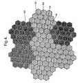
- the antenna panels of the second embodimentare not regular hexagons but that their outer edges 60 have castellations 62 .
- Each sub-array 66comprises nineteen radiating elements 64 arranged in a hexagonal configuration.
- the sub-arrays for each antenna paneloccupy the outer castellations 62 , and extend over into the adjacent edge regions 54 of the central base member 48 so as to preserve a regular hexagonal configuration.
- the central base member 48also has a similar array of hexagonal sub-arrays 66 .
- each panelhaving a configuration of hexagonal sub-arrays, the sub-arrays all being of the same shape and size.
- the resultis a phased array antenna of optimum configuration, having an approximately circular shape for large aperture, with the hexagonal arrays of radiator elements providing optimum beam forming characteristics.
- each sub array 66comprises a set of 19 radiating elements, a power divider which enables these elements to be excited by a single source with defined power division ratios and relative phases, a low noise amplifier (LNA) 78 for low noise signal reception, a high power amplifier (HPA) 80 for signal transmission, a bandpass filter 82 for rejecting unwanted, out of band transmissions from the HPA, and a diplexer 84 for combining the reception and transmission paths into a common path for connection to the set of radiating elements, and a beam-forming network.
- LNAlow noise amplifier
- HPAhigh power amplifier
- diplexer 84for combining the reception and transmission paths into a common path for connection to the set of radiating elements, and a beam-forming network.
- the LNA and diplexerare omitted.
- the HPA and bandpass filterare omitted, and the diplexer is replaced by a bandpass filter.
- An antenna panelis a combination of a modular design (for the assembly of LNA, HPA, diplexer and filters) and single structural elements (for the antenna front face carrying the radiating elements, the beam-formers, heat pipes and supporting structures). This arrangement results in reduced cost (for the modular assemblies), and reduced mass overall through the use of single structural elements.
- phased array antenna of the inventionas described, provides the following advantages:
- the embodimentsare in all respects exemplary and that modifications and variations are possible without departure from the spirit and scope of the invention.
- different shapes/sizes and/or a different number of antenna panelscould be used in the invention so as to realise the technical effect of the invention.
- the deployable phased array antenna of the inventioncould also be used for terrestrial communication systems in which a large phased array aperture is required but which must be transportable or easy to relocate.
Landscapes
- Engineering & Computer Science (AREA)
- Remote Sensing (AREA)
- Aviation & Aerospace Engineering (AREA)
- Physics & Mathematics (AREA)
- Astronomy & Astrophysics (AREA)
- General Physics & Mathematics (AREA)
- Computer Networks & Wireless Communication (AREA)
- Signal Processing (AREA)
- Details Of Aerials (AREA)
- Variable-Direction Aerials And Aerial Arrays (AREA)
- Aerials With Secondary Devices (AREA)
- Radio Relay Systems (AREA)
Abstract
Description
- A large antenna aperture enables generation of small spot beams permitting a high order of frequency re-use and enhancement of system capacity. The small beams also enhance the transmitter EIRP, and receive sensitivity enabling operation with small, low power, low cost terminals.
- A single phased array can replace a number of conventional reflector antennas. This feature provides the following benefits:
- Lower total antenna mass. This translates into lower spacecraft launch mass with attendant cost savings. Alternatively the antenna mass saving could be used for incorporating additional utility.
- More compact structure, and takes up less room than the reflector equivalents. Again this opens up the possibility of incorporating additional utility.
- Replacement of multiple reflector antennas by a single phased array simplifies deployment.
- Easier accommodation within the spacecraft launch vehicle.
- Potential cost reductions (only one phased array antenna to replace a number of reflector equivalents).
- A high degree of operational flexibility.
- The coverage provided by the phased array antenna can be reconfigured to match changing traffic distributions or new mission requirements.
- The array provides a method of adjusting the coverage to compensate for orbit inclination, thereby increasing the useful lifetime of the satellite and to compensate for satellite pointing errors.
- A method of designing antennas such that only small changes to a generic design are required to customise the antenna for different missions.
- Ability to compensate for antenna distortions, both during assembly, integration and test on the ground, and during operation in orbit.
- Less susceptibility to scatter effects, and shadowing by spacecraft structures than for reflector equivalents.
- The planar array can be a self-contained unit with active electronic units (HPAs and LNAs etc.) and filters integrated into the assembly. This enables the assembly, integration and test of the whole payload to be carried out more efficiently.
- The antenna aperture can be used as a thermal radiator.
Claims (18)
Applications Claiming Priority (6)
| Application Number | Priority Date | Filing Date | Title |
|---|---|---|---|
| EP05251558 | 2005-03-04 | ||
| EP05251558.2 | 2005-03-04 | ||
| GB0504521AGB0504521D0 (en) | 2005-03-04 | 2005-03-04 | Phased array antenna |
| GB0504521.6 | 2005-03-04 | ||
| EP05251558 | 2005-03-04 | ||
| PCT/GB2006/000782WO2006092625A1 (en) | 2005-03-04 | 2006-03-03 | Deployable phased array antenna for satellite communications |
Publications (2)
| Publication Number | Publication Date |
|---|---|
| US20080143636A1 US20080143636A1 (en) | 2008-06-19 |
| US7714797B2true US7714797B2 (en) | 2010-05-11 |
Family
ID=36203937
Family Applications (1)
| Application Number | Title | Priority Date | Filing Date |
|---|---|---|---|
| US10/585,098Active2028-10-07US7714797B2 (en) | 2005-03-04 | 2006-03-03 | Phased array antenna |
Country Status (7)
| Country | Link |
|---|---|
| US (1) | US7714797B2 (en) |
| EP (1) | EP1854228B1 (en) |
| CN (1) | CN101164251B (en) |
| AT (1) | ATE467279T1 (en) |
| DE (1) | DE602006014095D1 (en) |
| ES (1) | ES2343816T3 (en) |
| WO (1) | WO2006092625A1 (en) |
Cited By (17)
| Publication number | Priority date | Publication date | Assignee | Title |
|---|---|---|---|---|
| US20130082637A1 (en)* | 2011-09-30 | 2013-04-04 | Day and Night Solar, LLC | Portable solar panel power source |
| US8720830B1 (en) | 2012-01-30 | 2014-05-13 | United Launch Alliance, L.L.C. | Efficient solar panel wing-stowage on a space launch vehicle |
| US8730324B1 (en) | 2010-12-15 | 2014-05-20 | Skybox Imaging, Inc. | Integrated antenna system for imaging microsatellites |
| US20140263844A1 (en)* | 2013-03-15 | 2014-09-18 | The Boeing Company | Component Deployment System |
| US8905357B1 (en)* | 2009-10-02 | 2014-12-09 | MMA Design, LLC | Thin membrane structure |
| US9004409B1 (en)* | 2011-08-23 | 2015-04-14 | Space Systems/Loral, Llc | Extendable antenna reflector deployment techniques |
| US9248922B1 (en)* | 2011-08-23 | 2016-02-02 | Space Systems/Loral, Llc | Reflector deployment techniques for satellites |
| US20160197394A1 (en)* | 2013-09-06 | 2016-07-07 | MMA Design, LLC | Deployable Reflectarray Antenna Structure |
| US9550584B1 (en) | 2010-09-30 | 2017-01-24 | MMA Design, LLC | Deployable thin membrane apparatus |
| US20180201393A1 (en)* | 2017-01-18 | 2018-07-19 | Cory Lawrence Johns | Apparatus and method for packaging and deploying large structures using hexagons |
| US10053240B1 (en) | 2016-05-20 | 2018-08-21 | Space Systems/Loral, Llc | Stowage, deployment and positioning of rigid antenna reflectors on a spacecraft |
| US10353064B2 (en)* | 2016-05-26 | 2019-07-16 | Decisive Analytics Corporation | Method and apparatus for detecting airborne objects |
| US10368251B1 (en) | 2016-07-25 | 2019-07-30 | SpaceWorks Enterprises, Inc. | Satellites and satellite-based systems for ground-to-space short-burst data communications |
| US10367246B2 (en)* | 2015-04-30 | 2019-07-30 | Vilnius University | Easyly deployable phased antenna for a spacecraft and system of such antennas |
| US10396444B2 (en) | 2016-05-11 | 2019-08-27 | Panasonic Avionics Corporation | Antenna assembly |
| US10661918B2 (en)* | 2016-10-04 | 2020-05-26 | Space Systems/Loral, Llc | Self-assembling persistent space platform |
| US20230067936A1 (en)* | 2020-07-30 | 2023-03-02 | The Aerospace Corporation | Stackable satellite structure and deployment method |
Families Citing this family (49)
| Publication number | Priority date | Publication date | Assignee | Title |
|---|---|---|---|---|
| WO2008072016A1 (en)* | 2006-12-15 | 2008-06-19 | Roke Manor Research Limited | Deployable antenna array |
| GB2444802A (en)* | 2006-12-15 | 2008-06-18 | Roke Manor Research | Collapsible antenna array which can have a small radar cross section |
| US7797816B2 (en)* | 2008-02-21 | 2010-09-21 | Agence Spatiale Europeenne | Method of designing and manufacturing an array antenna |
| CN101369681B (en)* | 2008-09-27 | 2012-02-01 | 哈尔滨工程大学 | Framed antenna sequence deployment control device |
| CN101814660B (en)* | 2010-04-15 | 2013-03-20 | 京信通信系统(中国)有限公司 | Flat plate reflective array antenna |
| US8789796B2 (en)* | 2010-09-16 | 2014-07-29 | Space Systems/Loral, Llc | High capacity broadband satellite |
| US8665174B2 (en)* | 2011-01-13 | 2014-03-04 | The Boeing Company | Triangular phased array antenna subarray |
| US9966658B2 (en)* | 2012-06-11 | 2018-05-08 | University Of Florida Research Foundation, Inc. | Antennas for small satellites |
| US9322911B1 (en)* | 2013-08-27 | 2016-04-26 | Exelis, Inc. | Passive phased array imager using sub-phase sampling CMOS detectors and a smart ROIC |
| EP2863473B1 (en)* | 2013-10-16 | 2019-03-20 | Airbus Defence and Space GmbH | Space-Borne Antenna System |
| US9352856B1 (en)* | 2013-12-04 | 2016-05-31 | Space Systems/Loral, Llc | Axially grooved crossing heat pipes |
| USD756887S1 (en)* | 2013-12-20 | 2016-05-24 | Andrew Simon Filo | Cubesat with a chipsat deployer |
| IL230180A0 (en)* | 2013-12-26 | 2014-08-31 | Israel Aerospace Ind Ltd | Space vehicle |
| IL233902B (en) | 2014-07-31 | 2020-07-30 | Israel Aerospace Ind Ltd | egnition system |
| US9856039B2 (en)* | 2014-10-08 | 2018-01-02 | Analytical Mechanics Associates, Inc. | Extendable solar array for a spacecraft system |
| FR3031969B1 (en)* | 2015-01-27 | 2017-01-27 | Airbus Defence & Space Sas | ARTIFICIAL SATELLITE AND METHOD FOR FILLING A PROPULSIVE GAS TANK OF SAID ARTIFICIAL SATELLITE |
| US9878806B2 (en) | 2015-03-09 | 2018-01-30 | Space Systems/Loral, Llc | On-orbit assembly of communication satellites |
| US9745083B2 (en)* | 2015-04-01 | 2017-08-29 | Worldvu Satellites Limited | Method for thermal stabilization of a communications satellite |
| US9718566B2 (en)* | 2015-04-30 | 2017-08-01 | Worldvu Satellites Limited | Stackable satellites and method of stacking same |
| US10189583B2 (en)* | 2015-05-13 | 2019-01-29 | Analytical Mechanics Associates, Inc. | Deployable sheet material systems and methods |
| CN104966892B (en)* | 2015-05-18 | 2017-08-04 | 西北工业大学 | A regular hexagon planar unfolding mechanism |
| JP6448819B2 (en)* | 2015-06-02 | 2019-01-09 | エアバス ディフェンス アンド スペース エスアーエス | Satellite |
| CN105356029B (en)* | 2015-11-09 | 2018-06-22 | 哈尔滨工业大学 | Plane reflection array antenna and its method of deploying based on shape memory polymer composite material hinge |
| CN106898855B (en)* | 2015-12-18 | 2020-02-07 | 航天恒星科技有限公司 | Portable antenna |
| CN106410361B (en)* | 2016-08-29 | 2019-01-15 | 中国电子科技集团公司第三十六研究所 | A kind of vehicle-mounted detecting antenna |
| US10730643B1 (en) | 2016-09-08 | 2020-08-04 | Space Systems/Loral, Llc | Space based robotic assembly of a modular reflector |
| US10435182B1 (en) | 2016-09-12 | 2019-10-08 | Space Systems/Loral, Llc | Articulation techniques for a spacecraft solar array |
| CN107994320B (en)* | 2016-10-17 | 2020-12-29 | 中国航空制造技术研究院 | Vehicle-mounted equipment antenna combination protection casing |
| US10177460B2 (en)* | 2017-04-24 | 2019-01-08 | Blue Digs LLC | Satellite array architecture |
| US10135519B1 (en)* | 2017-06-19 | 2018-11-20 | Pinnacle Vista, LLC | Antenna assembly system |
| US10800551B2 (en)* | 2017-06-21 | 2020-10-13 | Space Systems/Loral, Llc | High capacity communication satellite |
| US10957986B2 (en)* | 2017-08-04 | 2021-03-23 | Space Systems/Loral, Llc | Reconfigurable spacecraft with a hold-down assembly for a rigid reflector |
| CN108736956B (en)* | 2018-04-09 | 2020-04-24 | 浙江大学 | Marine satellite communication networking method based on spherical digital phased array system |
| CN109560862A (en)* | 2019-01-23 | 2019-04-02 | 长沙天仪空间科技研究院有限公司 | A kind of Inter-satellite Communication System and method based on Satellite Formation Flying |
| EP4055662A1 (en)* | 2019-11-04 | 2022-09-14 | Isotropic Systems Ltd | Circuit and system apparatus for synthesizing one or multiple beams on a switched-feed antenna |
| US10854971B1 (en)* | 2020-04-24 | 2020-12-01 | The Florida International University Board Of Trustees | Reconfigurable arrays with foldable panels |
| RU205102U1 (en)* | 2020-06-22 | 2021-06-28 | Общество с ограниченной ответственностью "Лоретт" | ANTENNA STATION FOR RECEIVING SIGNALS OF AES OF INCREASED HARDNESS |
| CN112265656B (en)* | 2020-09-23 | 2021-12-07 | 北京空间飞行器总体设计部 | Packaging and containing type on-orbit assembly device and method for long-length antenna |
| CN112563762B (en)* | 2020-11-27 | 2022-11-11 | 西安空间无线电技术研究所 | One-driving-four-time unfolding antenna control method |
| US20240006778A1 (en)* | 2020-11-30 | 2024-01-04 | Macdonald, Dettwiler And Associates Corporation | Direct radiating array ("dra") antenna, method of assembling a dra antenna, and system for managing heat generated by a dra antenna |
| CN113078481B (en)* | 2021-04-02 | 2022-08-02 | 大连海事大学 | Miniaturized Dual Frequency Microstrip Array Antenna |
| US11569904B1 (en) | 2021-08-02 | 2023-01-31 | Hubble Network Inc. | Differentiating orthogonally modulated signals received from multiple transmitters at one or more antenna arrays |
| US11283516B1 (en) | 2021-08-02 | 2022-03-22 | Hubble Network Inc | Multi spoke beamforming for low power wide area satellite and terrestrial networks |
| US20250197030A1 (en)* | 2021-12-02 | 2025-06-19 | Fleet Space Technologies Pty Ltd | Small leo satellite systems and methods |
| CN114430100B (en)* | 2022-02-15 | 2023-10-13 | 长沙天仪空间科技研究院有限公司 | Satellite-borne antenna unfolding control system |
| CN115395202B (en)* | 2022-09-14 | 2024-05-03 | 深圳市魔方卫星科技有限公司 | Space-borne synthetic aperture radar phased array antenna lamination unfolding device |
| CN117262242B (en)* | 2023-11-17 | 2024-01-30 | 哈尔滨工大卫星技术有限公司 | Planar unfolding three-dimensional cabin door device applied to primary and secondary stars and working method |
| CN118387318B (en)* | 2024-06-27 | 2024-09-13 | 哈尔滨工业大学(深圳)(哈尔滨工业大学深圳科技创新研究院) | Flat-plate array type thin-film spacecraft and control method |
| CN120527603B (en)* | 2025-07-25 | 2025-09-23 | 哈尔滨工大卫星技术有限公司 | A multi-fold deployment device for a phased array antenna and its assembly and operating method |
Citations (11)
| Publication number | Priority date | Publication date | Assignee | Title |
|---|---|---|---|---|
| US4854526A (en) | 1987-08-10 | 1989-08-08 | Hughes Aircraft Company | Spacecraft design enabling the compact nesting of multiple spacecraft in the launch vehicle |
| US5052640A (en) | 1989-08-29 | 1991-10-01 | Hughes Aircraft Company | Spacecraft design enabling the flat packing of multiple spacecraft in the launch vehicle |
| WO1994002972A1 (en) | 1992-07-16 | 1994-02-03 | Calling Communications Corporation | Spacecraft intersatellite link for satellite communication system |
| WO1994029927A1 (en) | 1993-06-11 | 1994-12-22 | Teledesic Corporation | Modular communication satellite |
| JPH07223597A (en) | 1994-02-08 | 1995-08-22 | Mitsubishi Electric Corp | Two-dimensional structure |
| US5642122A (en) | 1991-11-08 | 1997-06-24 | Teledesic Corporation | Spacecraft antennas and beam steering methods for satellite communciation system |
| US5641135A (en) | 1991-11-08 | 1997-06-24 | Teledesic Corporation | Inflatable torus and collapsible hinged disc spacecraft designs for satellite communication system |
| US5927654A (en) | 1997-05-16 | 1999-07-27 | Lockheed Martin Corp. | Spacecraft with active antenna array protected against temperature extremes |
| US20020074458A1 (en) | 1998-11-02 | 2002-06-20 | Peter B. Laraway | Spacecraft with deployable panel array |
| US6505381B1 (en) | 1999-07-30 | 2003-01-14 | Trw Astro Aerospace | Pulley actuated translational hinge system |
| US6568640B1 (en) | 1999-07-22 | 2003-05-27 | Lockheed Martin Corporation | Inflatable satellite design |
Family Cites Families (1)
| Publication number | Priority date | Publication date | Assignee | Title |
|---|---|---|---|---|
| CN1232738C (en)* | 2003-05-22 | 2005-12-21 | 上海交通大学 | High-rigidity synchronously spreading folded space extension arm |
- 2006
- 2006-03-03EPEP06726348Apatent/EP1854228B1/ennot_activeNot-in-force
- 2006-03-03ESES06726348Tpatent/ES2343816T3/enactiveActive
- 2006-03-03ATAT06726348Tpatent/ATE467279T1/ennot_activeIP Right Cessation
- 2006-03-03WOPCT/GB2006/000782patent/WO2006092625A1/enactiveApplication Filing
- 2006-03-03USUS10/585,098patent/US7714797B2/enactiveActive
- 2006-03-03DEDE602006014095Tpatent/DE602006014095D1/enactiveActive
- 2006-03-03CNCN2006800132432Apatent/CN101164251B/ennot_activeExpired - Fee Related
Patent Citations (12)
| Publication number | Priority date | Publication date | Assignee | Title |
|---|---|---|---|---|
| US4854526A (en) | 1987-08-10 | 1989-08-08 | Hughes Aircraft Company | Spacecraft design enabling the compact nesting of multiple spacecraft in the launch vehicle |
| US5052640A (en) | 1989-08-29 | 1991-10-01 | Hughes Aircraft Company | Spacecraft design enabling the flat packing of multiple spacecraft in the launch vehicle |
| US5642122A (en) | 1991-11-08 | 1997-06-24 | Teledesic Corporation | Spacecraft antennas and beam steering methods for satellite communciation system |
| US5641135A (en) | 1991-11-08 | 1997-06-24 | Teledesic Corporation | Inflatable torus and collapsible hinged disc spacecraft designs for satellite communication system |
| WO1994002972A1 (en) | 1992-07-16 | 1994-02-03 | Calling Communications Corporation | Spacecraft intersatellite link for satellite communication system |
| WO1994029927A1 (en) | 1993-06-11 | 1994-12-22 | Teledesic Corporation | Modular communication satellite |
| US5527001A (en)* | 1993-06-11 | 1996-06-18 | Teledesic Corporation | Modular communication satellite |
| JPH07223597A (en) | 1994-02-08 | 1995-08-22 | Mitsubishi Electric Corp | Two-dimensional structure |
| US5927654A (en) | 1997-05-16 | 1999-07-27 | Lockheed Martin Corp. | Spacecraft with active antenna array protected against temperature extremes |
| US20020074458A1 (en) | 1998-11-02 | 2002-06-20 | Peter B. Laraway | Spacecraft with deployable panel array |
| US6568640B1 (en) | 1999-07-22 | 2003-05-27 | Lockheed Martin Corporation | Inflatable satellite design |
| US6505381B1 (en) | 1999-07-30 | 2003-01-14 | Trw Astro Aerospace | Pulley actuated translational hinge system |
Non-Patent Citations (2)
| Title |
|---|
| J.L. Blonstein, "Communication Satellites, The Technology of Space Communications", published 1987 by Heinemann, p. 147. |
| W.E. Hardy, "ERS-1 AMI Antennas: The Design and Development Experience", Marconi Space Systems, Portsmouth, United Kingdom, Proceedings of IGARSS '88 Symposium, Edinburgh, Scotland, Sep. 13-16, 1988, Ref. ESA SP-284 (IEEE 88CH2497-6), Published by ESA Publications Division, Aug. 1988, pp. 873-876. |
Cited By (25)
| Publication number | Priority date | Publication date | Assignee | Title |
|---|---|---|---|---|
| US8905357B1 (en)* | 2009-10-02 | 2014-12-09 | MMA Design, LLC | Thin membrane structure |
| US9550584B1 (en) | 2010-09-30 | 2017-01-24 | MMA Design, LLC | Deployable thin membrane apparatus |
| US8730324B1 (en) | 2010-12-15 | 2014-05-20 | Skybox Imaging, Inc. | Integrated antenna system for imaging microsatellites |
| US8786703B1 (en) | 2010-12-15 | 2014-07-22 | Skybox Imaging, Inc. | Integrated antenna system for imaging microsatellites |
| US9013577B2 (en) | 2010-12-15 | 2015-04-21 | Skybox Imaging, Inc. | Integrated antenna system for imaging microsatellites |
| US9004409B1 (en)* | 2011-08-23 | 2015-04-14 | Space Systems/Loral, Llc | Extendable antenna reflector deployment techniques |
| US9248922B1 (en)* | 2011-08-23 | 2016-02-02 | Space Systems/Loral, Llc | Reflector deployment techniques for satellites |
| US20130082637A1 (en)* | 2011-09-30 | 2013-04-04 | Day and Night Solar, LLC | Portable solar panel power source |
| US8720830B1 (en) | 2012-01-30 | 2014-05-13 | United Launch Alliance, L.L.C. | Efficient solar panel wing-stowage on a space launch vehicle |
| US9637247B2 (en)* | 2013-03-15 | 2017-05-02 | The Boeing Company | Component deployment system |
| US9637248B2 (en)* | 2013-03-15 | 2017-05-02 | The Boeing Company | Component deployment system |
| US20140263844A1 (en)* | 2013-03-15 | 2014-09-18 | The Boeing Company | Component Deployment System |
| US10763569B2 (en) | 2013-09-06 | 2020-09-01 | M.M.A. Design, LLC | Deployable reflectarray antenna structure |
| US11901605B2 (en) | 2013-09-06 | 2024-02-13 | M.M.A. Design, LLC | Deployable antenna structure |
| US10263316B2 (en)* | 2013-09-06 | 2019-04-16 | MMA Design, LLC | Deployable reflectarray antenna structure |
| US20160197394A1 (en)* | 2013-09-06 | 2016-07-07 | MMA Design, LLC | Deployable Reflectarray Antenna Structure |
| US10826157B2 (en) | 2013-09-06 | 2020-11-03 | MMA Design, LLC | Deployable reflectarray antenna structure |
| US10367246B2 (en)* | 2015-04-30 | 2019-07-30 | Vilnius University | Easyly deployable phased antenna for a spacecraft and system of such antennas |
| US10396444B2 (en) | 2016-05-11 | 2019-08-27 | Panasonic Avionics Corporation | Antenna assembly |
| US10053240B1 (en) | 2016-05-20 | 2018-08-21 | Space Systems/Loral, Llc | Stowage, deployment and positioning of rigid antenna reflectors on a spacecraft |
| US10353064B2 (en)* | 2016-05-26 | 2019-07-16 | Decisive Analytics Corporation | Method and apparatus for detecting airborne objects |
| US10368251B1 (en) | 2016-07-25 | 2019-07-30 | SpaceWorks Enterprises, Inc. | Satellites and satellite-based systems for ground-to-space short-burst data communications |
| US10661918B2 (en)* | 2016-10-04 | 2020-05-26 | Space Systems/Loral, Llc | Self-assembling persistent space platform |
| US20180201393A1 (en)* | 2017-01-18 | 2018-07-19 | Cory Lawrence Johns | Apparatus and method for packaging and deploying large structures using hexagons |
| US20230067936A1 (en)* | 2020-07-30 | 2023-03-02 | The Aerospace Corporation | Stackable satellite structure and deployment method |
Also Published As
| Publication number | Publication date |
|---|---|
| CN101164251A (en) | 2008-04-16 |
| WO2006092625A1 (en) | 2006-09-08 |
| ATE467279T1 (en) | 2010-05-15 |
| EP1854228A1 (en) | 2007-11-14 |
| EP1854228B1 (en) | 2010-05-05 |
| US20080143636A1 (en) | 2008-06-19 |
| CN101164251B (en) | 2012-04-18 |
| ES2343816T3 (en) | 2010-08-10 |
| DE602006014095D1 (en) | 2010-06-17 |
Similar Documents
| Publication | Publication Date | Title |
|---|---|---|
| US7714797B2 (en) | Phased array antenna | |
| Gao et al. | Advanced antennas for small satellites | |
| CN106848558B (en) | Solar sailboard conformal antenna of spacecraft | |
| US6121931A (en) | Planar dual-frequency array antenna | |
| Huang | Capabilities of printed reflectarray antennas | |
| US6388634B1 (en) | Multi-beam antenna communication system and method | |
| US12101853B2 (en) | Base station antenna units having arrays spanning multiple antennas that are connected by jumper cables | |
| CN100365866C (en) | Patch dipole array antenna including feed line organizer body and related methods | |
| CN106688141A (en) | Omnidirectional antenna for mobile communication service | |
| CN108011190A (en) | Multi-band integrated wide-area detection receiving antenna | |
| US11223126B1 (en) | Combined cross-link and communication-link phased array for satellite communication | |
| US6580401B1 (en) | Bifocal planar antenna | |
| US11158951B2 (en) | Antipodal vivaldi antenna systems | |
| Amyotte et al. | Antennas for satellite communications | |
| Zaghloul et al. | Low cost flat antennas for commercial and military SATCOM terminals | |
| Gurbet et al. | Comprehensive Review of Ku, K, and Ka Band Antenna Designs: Applications in CubeSats | |
| Yang | High-efficiency passive and active phased arrays and array feeds for satellite communications | |
| Varum et al. | STRx–Transmission and Reception System with Electronical Orientation for LEO SatCom Constellations | |
| Takahashi et al. | Dual-Beam and Wide-Angle Steering AESA with Antenna Size Scalability for Ka-Band SATCOM | |
| Kummer et al. | A high-gain self-steering microwave array | |
| Kabacik et al. | Lightweight conformal dual band antenna for spaceborne applications | |
| Maddocks et al. | Flat-plate steerable antennas for satellite communications and broadcast reception | |
| Yasaka et al. | Multi-band multi-beam antenna complex for orbit experiment | |
| Séguin et al. | SAR antenna development in Canada | |
| Zaghloul et al. | Low-cost flat antennas for mobile and wireless communications |
Legal Events
| Date | Code | Title | Description |
|---|---|---|---|
| AS | Assignment | Owner name:EADS ASTRIUM LIMITED, GREAT BRITAIN Free format text:ASSIGNMENT OF ASSIGNORS INTEREST;ASSIGNORS:COUCHMAN, ALAN;RUSSELL, ADRIAN;REEL/FRAME:018070/0898 Effective date:20060407 Owner name:EADS ASTRIUM LIMITED,GREAT BRITAIN Free format text:ASSIGNMENT OF ASSIGNORS INTEREST;ASSIGNORS:COUCHMAN, ALAN;RUSSELL, ADRIAN;REEL/FRAME:018070/0898 Effective date:20060407 | |
| AS | Assignment | Owner name:ASTRIUM LIMITED, UNITED KINGDOM Free format text:CHANGE OF NAME;ASSIGNOR:EADS ASTRIUM LIMITED;REEL/FRAME:021805/0488 Effective date:20060630 Owner name:ASTRIUM LIMITED,UNITED KINGDOM Free format text:CHANGE OF NAME;ASSIGNOR:EADS ASTRIUM LIMITED;REEL/FRAME:021805/0488 Effective date:20060630 | |
| STCF | Information on status: patent grant | Free format text:PATENTED CASE | |
| FEPP | Fee payment procedure | Free format text:PAYOR NUMBER ASSIGNED (ORIGINAL EVENT CODE: ASPN); ENTITY STATUS OF PATENT OWNER: LARGE ENTITY | |
| FPAY | Fee payment | Year of fee payment:4 | |
| MAFP | Maintenance fee payment | Free format text:PAYMENT OF MAINTENANCE FEE, 8TH YEAR, LARGE ENTITY (ORIGINAL EVENT CODE: M1552) Year of fee payment:8 | |
| MAFP | Maintenance fee payment | Free format text:PAYMENT OF MAINTENANCE FEE, 12TH YEAR, LARGE ENTITY (ORIGINAL EVENT CODE: M1553); ENTITY STATUS OF PATENT OWNER: LARGE ENTITY Year of fee payment:12 |