US7713286B2 - Knotless suture anchor - Google Patents
Knotless suture anchorDownload PDFInfo
- Publication number
- US7713286B2 US7713286B2US10/712,285US71228503AUS7713286B2US 7713286 B2US7713286 B2US 7713286B2US 71228503 AUS71228503 AUS 71228503AUS 7713286 B2US7713286 B2US 7713286B2
- Authority
- US
- United States
- Prior art keywords
- suture
- aperture
- suture anchor
- transverse
- anchor
- Prior art date
- Legal status (The legal status is an assumption and is not a legal conclusion. Google has not performed a legal analysis and makes no representation as to the accuracy of the status listed.)
- Expired - Fee Related, expires
Links
- 210000000988bone and boneAnatomy0.000claimsdescription31
- 230000007246mechanismEffects0.000claimsdescription26
- 238000004873anchoringMethods0.000claimsdescription7
- 239000000463materialSubstances0.000claimsdescription6
- 238000003780insertionMethods0.000claimsdescription4
- 230000037431insertionEffects0.000claimsdescription4
- 239000011800void materialSubstances0.000claims1
- 210000001519tissueAnatomy0.000description16
- 229920000642polymerPolymers0.000description7
- 238000000034methodMethods0.000description5
- 210000004872soft tissueAnatomy0.000description5
- 230000033001locomotionEffects0.000description4
- -1stainless steelsChemical class0.000description3
- 239000000654additiveSubstances0.000description2
- 230000008468bone growthEffects0.000description2
- 210000000845cartilageAnatomy0.000description2
- 229910052751metalInorganic materials0.000description2
- 239000002184metalSubstances0.000description2
- 150000002739metalsChemical class0.000description2
- 238000000465mouldingMethods0.000description2
- 229920000728polyesterPolymers0.000description2
- 238000003466weldingMethods0.000description2
- RKDVKSZUMVYZHH-UHFFFAOYSA-N1,4-dioxane-2,5-dioneChemical compoundO=C1COC(=O)CO1RKDVKSZUMVYZHH-UHFFFAOYSA-N0.000description1
- 229910000684Cobalt-chromeInorganic materials0.000description1
- OUYCCCASQSFEME-QMMMGPOBSA-NL-tyrosineChemical compoundOC(=O)[C@@H](N)CC1=CC=C(O)C=C1OUYCCCASQSFEME-QMMMGPOBSA-N0.000description1
- 239000004952PolyamideSubstances0.000description1
- 229920002732PolyanhydridePolymers0.000description1
- 239000004642PolyimideSubstances0.000description1
- 229910000831SteelInorganic materials0.000description1
- 208000002847Surgical WoundDiseases0.000description1
- 229910001069Ti alloyInorganic materials0.000description1
- RTAQQCXQSZGOHL-UHFFFAOYSA-NTitaniumChemical compound[Ti]RTAQQCXQSZGOHL-UHFFFAOYSA-N0.000description1
- HZEWFHLRYVTOIW-UHFFFAOYSA-N[Ti].[Ni]Chemical compound[Ti].[Ni]HZEWFHLRYVTOIW-UHFFFAOYSA-N0.000description1
- 210000003815abdominal wallAnatomy0.000description1
- 238000005299abrasionMethods0.000description1
- 229910045601alloyInorganic materials0.000description1
- 239000000956alloySubstances0.000description1
- 210000003423ankleAnatomy0.000description1
- 230000008901benefitEffects0.000description1
- 239000000560biocompatible materialSubstances0.000description1
- 230000005540biological transmissionEffects0.000description1
- 230000015572biosynthetic processEffects0.000description1
- 239000010952cobalt-chromeSubstances0.000description1
- 238000010276constructionMethods0.000description1
- 230000001054cortical effectEffects0.000description1
- 238000002788crimpingMethods0.000description1
- KPUWHANPEXNPJT-UHFFFAOYSA-NdisiloxaneChemical class[SiH3]O[SiH3]KPUWHANPEXNPJT-UHFFFAOYSA-N0.000description1
- 210000001513elbowAnatomy0.000description1
- 229920002313fluoropolymerPolymers0.000description1
- 210000001624hipAnatomy0.000description1
- 239000007943implantSubstances0.000description1
- 238000002347injectionMethods0.000description1
- 239000007924injectionSubstances0.000description1
- 210000001503jointAnatomy0.000description1
- 210000003127kneeAnatomy0.000description1
- JJTUDXZGHPGLLC-UHFFFAOYSA-NlactideChemical compoundCC1OC(=O)C(C)OC1=OJJTUDXZGHPGLLC-UHFFFAOYSA-N0.000description1
- 210000003041ligamentAnatomy0.000description1
- 238000003754machiningMethods0.000description1
- 230000013011matingEffects0.000description1
- 230000005499meniscusEffects0.000description1
- 238000012986modificationMethods0.000description1
- 230000004048modificationEffects0.000description1
- 210000003205muscleAnatomy0.000description1
- 229910001000nickel titaniumInorganic materials0.000description1
- 230000000278osteoconductive effectEffects0.000description1
- 230000002138osteoinductive effectEffects0.000description1
- 210000003049pelvic boneAnatomy0.000description1
- 229920001308poly(aminoacid)Polymers0.000description1
- 229920000747poly(lactic acid)Polymers0.000description1
- 229920000058polyacrylatePolymers0.000description1
- 229920002647polyamidePolymers0.000description1
- 229920001721polyimidePolymers0.000description1
- 229920000098polyolefinPolymers0.000description1
- 235000018102proteinsNutrition0.000description1
- 102000004169proteins and genesHuman genes0.000description1
- 108090000623proteins and genesProteins0.000description1
- 238000004080punchingMethods0.000description1
- 210000000513rotator cuffAnatomy0.000description1
- 210000002832shoulderAnatomy0.000description1
- 210000000323shoulder jointAnatomy0.000description1
- 238000005245sinteringMethods0.000description1
- 229910001220stainless steelInorganic materials0.000description1
- 239000010959steelSubstances0.000description1
- 239000000126substanceSubstances0.000description1
- 238000001356surgical procedureMethods0.000description1
- 229910052715tantalumInorganic materials0.000description1
- GUVRBAGPIYLISA-UHFFFAOYSA-Ntantalum atomChemical compound[Ta]GUVRBAGPIYLISA-UHFFFAOYSA-N0.000description1
- 239000010936titaniumSubstances0.000description1
- 229910052719titaniumInorganic materials0.000description1
- 230000007704transitionEffects0.000description1
- QORWJWZARLRLPR-UHFFFAOYSA-Htricalcium bis(phosphate)Chemical compound[Ca+2].[Ca+2].[Ca+2].[O-]P([O-])([O-])=O.[O-]P([O-])([O-])=OQORWJWZARLRLPR-UHFFFAOYSA-H0.000description1
- OUYCCCASQSFEME-UHFFFAOYSA-NtyrosineNatural productsOC(=O)C(N)CC1=CC=C(O)C=C1OUYCCCASQSFEME-UHFFFAOYSA-N0.000description1
- 230000002485urinary effectEffects0.000description1
- 210000000707wristAnatomy0.000description1
Images


Classifications
- A—HUMAN NECESSITIES
- A61—MEDICAL OR VETERINARY SCIENCE; HYGIENE
- A61B—DIAGNOSIS; SURGERY; IDENTIFICATION
- A61B17/00—Surgical instruments, devices or methods
- A61B17/04—Surgical instruments, devices or methods for suturing wounds; Holders or packages for needles or suture materials
- A61B17/0401—Suture anchors, buttons or pledgets, i.e. means for attaching sutures to bone, cartilage or soft tissue; Instruments for applying or removing suture anchors
- A—HUMAN NECESSITIES
- A61—MEDICAL OR VETERINARY SCIENCE; HYGIENE
- A61B—DIAGNOSIS; SURGERY; IDENTIFICATION
- A61B17/00—Surgical instruments, devices or methods
- A61B17/04—Surgical instruments, devices or methods for suturing wounds; Holders or packages for needles or suture materials
- A61B17/0487—Suture clamps, clips or locks, e.g. for replacing suture knots; Instruments for applying or removing suture clamps, clips or locks
- A—HUMAN NECESSITIES
- A61—MEDICAL OR VETERINARY SCIENCE; HYGIENE
- A61B—DIAGNOSIS; SURGERY; IDENTIFICATION
- A61B17/00—Surgical instruments, devices or methods
- A61B17/04—Surgical instruments, devices or methods for suturing wounds; Holders or packages for needles or suture materials
- A61B17/0401—Suture anchors, buttons or pledgets, i.e. means for attaching sutures to bone, cartilage or soft tissue; Instruments for applying or removing suture anchors
- A61B2017/0409—Instruments for applying suture anchors
- A—HUMAN NECESSITIES
- A61—MEDICAL OR VETERINARY SCIENCE; HYGIENE
- A61B—DIAGNOSIS; SURGERY; IDENTIFICATION
- A61B17/00—Surgical instruments, devices or methods
- A61B17/04—Surgical instruments, devices or methods for suturing wounds; Holders or packages for needles or suture materials
- A61B17/0401—Suture anchors, buttons or pledgets, i.e. means for attaching sutures to bone, cartilage or soft tissue; Instruments for applying or removing suture anchors
- A61B2017/0414—Suture anchors, buttons or pledgets, i.e. means for attaching sutures to bone, cartilage or soft tissue; Instruments for applying or removing suture anchors having a suture-receiving opening, e.g. lateral opening
- A—HUMAN NECESSITIES
- A61—MEDICAL OR VETERINARY SCIENCE; HYGIENE
- A61B—DIAGNOSIS; SURGERY; IDENTIFICATION
- A61B17/00—Surgical instruments, devices or methods
- A61B17/04—Surgical instruments, devices or methods for suturing wounds; Holders or packages for needles or suture materials
- A61B17/0401—Suture anchors, buttons or pledgets, i.e. means for attaching sutures to bone, cartilage or soft tissue; Instruments for applying or removing suture anchors
- A61B2017/044—Suture anchors, buttons or pledgets, i.e. means for attaching sutures to bone, cartilage or soft tissue; Instruments for applying or removing suture anchors with a threaded shaft, e.g. screws
- A—HUMAN NECESSITIES
- A61—MEDICAL OR VETERINARY SCIENCE; HYGIENE
- A61B—DIAGNOSIS; SURGERY; IDENTIFICATION
- A61B17/00—Surgical instruments, devices or methods
- A61B17/04—Surgical instruments, devices or methods for suturing wounds; Holders or packages for needles or suture materials
- A61B17/0401—Suture anchors, buttons or pledgets, i.e. means for attaching sutures to bone, cartilage or soft tissue; Instruments for applying or removing suture anchors
- A61B2017/0446—Means for attaching and blocking the suture in the suture anchor
- A61B2017/0454—Means for attaching and blocking the suture in the suture anchor the anchor being crimped or clamped on the suture
- A—HUMAN NECESSITIES
- A61—MEDICAL OR VETERINARY SCIENCE; HYGIENE
- A61B—DIAGNOSIS; SURGERY; IDENTIFICATION
- A61B17/00—Surgical instruments, devices or methods
- A61B17/04—Surgical instruments, devices or methods for suturing wounds; Holders or packages for needles or suture materials
- A61B17/0401—Suture anchors, buttons or pledgets, i.e. means for attaching sutures to bone, cartilage or soft tissue; Instruments for applying or removing suture anchors
- A61B2017/0446—Means for attaching and blocking the suture in the suture anchor
- A61B2017/0458—Longitudinal through hole, e.g. suture blocked by a distal suture knot
Definitions
- the present inventionrelates to surgical implants.
- the inventionrelates to suture anchors used to anchor a suture to a first portion of a body, the suture being used to attach a second portion of the body adjacent to the first portion.
- the inventionrelates to a method and a suture anchor capable of securing a suture to a portion of a body without the need to tie any knots in the suture.
- Suture anchorsare often used in surgical procedures requiring the attachment of one tissue to another such as in attaching a soft tissue to a bone.
- Typical suture anchorsare threaded or pressed into a hole drilled in the bone and include a suture that trails away from the anchor. The suture is then threaded through the tissue to be attached and knots are tied in the suture to hold the tissue against the bone adjacent the hole.
- One shortcoming of prior art suture anchorsis the necessity of tying a knot which adds steps to the procedure, weakens the suture, and increases the complexity of the operation, especially in the tight confines of an arthroscopic or minimally invasive surgical wound.
- the present inventionprovides a suture anchor capable of securing a suture to a body tissue.
- a suture anchorin one aspect of the invention, includes a distal body portion for securing the suture anchor in body tissue, an aperture for receiving a portion of the suture, and a deformable body portion for deforming the aperture to compress and grip the suture.
- a unitary suture anchorin another aspect of the invention, includes a distal body portion for securing the suture anchor to a bone.
- a proximal body portionsecures the suture to the suture anchor and includes a pair of elongated and relatively movable first body members. At least one of the first body members is hingedly connected to the distal body portion and the first body members are relatively movable between a suture receiving position and a suture locking position.
- a transverse suture receiving apertureis interposed between the first body members for receiving the suture when the first body members are in the suture receiving position. The aperture is deformed to grip the suture when the first body members are in the suture locking position.
- a method for securing a suture to a body tissueincludes: providing a suture anchor having a distal body portion for securing the suture anchor in the body tissue, an aperture for receiving a portion of the suture, and a deformable body portion for deforming the aperture to compress and grip the suture; inserting a portion of the suture through the aperture; deforming the deformable body portion to deform the aperture and grip the suture; and inserting the suture anchor into the body tissue.
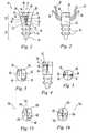
- FIG. 1is a front plan view of an illustrative suture anchor according to the present invention and shown in an open position.
- FIG. 2is a side plan view of the suture anchor of FIG. 1 .
- FIG. 3is a top plan view of the suture anchor of FIG. 1 .
- FIG. 4is a front plan view of the suture anchor of FIG. 1 shown in a closed position.
- FIG. 5is a top plan view of the suture anchor of FIG. 1 shown in a closed position.
- FIG. 6is a front plan view of the suture anchor of FIG. 1 shown with an optional horizontal eyelet in the open position.
- FIG. 7is a front plan view of the suture anchor of FIG. 1 shown with an optional preloaded suture in the open position.
- FIG. 8is a front plan view of the suture anchor of FIG. 1 shown with an optional driver interface in the open position and assembled to a driver.
- FIG. 9is a top plan view of the suture anchor of FIG. 8 shown with an optional locking mechanism in the unlocked position.
- FIG. 10is a top plan view of the suture anchor of FIG. 8 shown with the optional locking mechanism of FIG. 9 in the locked position.
- FIG. 11is a top plan view of the suture anchor of FIG. 8 shown with an optional locking mechanism in the unlocked position.
- FIG. 12is a top plan view of the suture anchor of FIG. 8 shown with the optional locking mechanism of FIG. 11 in the locked position.
- FIG. 13is a top plan view of the suture anchor of FIG. 1 shown with an optional locking mechanism in the unlocked position.
- FIG. 14is a top plan view of the suture anchor of FIG. 1 shown with an optional locking mechanism the unlocked position.
- FIGS. 15-17are partial side section views showing the stages of use of the suture anchor of FIG. 1 .
- Embodiments of a suture anchorinclude a portion for anchoring the suture anchor in tissue and a portion for gripping a suture. These portions may be separate components or may be combined into a single multipurpose component.
- the suture anchor of the present inventionmay be used to anchor a suture to any appropriate tissue.
- the anchor portion of the suture anchormay include a variety of configurations to adapt it for use in tissues having different mechanical properties.
- the anchormay be adapted for use in meniscus, cartilage, cancellous bone, cortical bone and/or other soft and hard tissues.
- the anchormay be used to attach muscle tissue, cartilage, bone, prosthetic devices and/or other substances via the suture and suture gripping portion.
- the suture anchormay be used to attach soft tissues associated with the skeletal system to a bone such as a ligament to the bone surrounding a skeletal joint.
- the jointmay include the hip, knee, shoulder, wrist, elbow, ankle, vertebral, phalangeal, temporomandibular, and other joints and locations within a patient's body.
- the suture anchormay be used to attach a non-skeletal soft tissue to a bone such as attaching a urinary structure to the pelvic bone.
- the suture anchormay be used to attach a soft tissue or prosthetic device within a body cavity such as anchoring soft tissue or a prosthetic device to the abdominal wall.
- Other examples of attaching items together within a patient's bodywill be apparent and fall within the scope of the invention.
- a suture anchoris depicted for use in securing a portion of the rotator cuff to a bone adjacent a human shoulder joint. It will be understood by those skilled in the art that this application is illustrative only and that the suture anchor is usable in other applications.
- FIGS. 1-5show an illustrative knotless suture anchor 10 including a body 12 having a distal end 14 configured to be anchored in a bone and a proximal end 16 configured to grip a suture.
- the distal end 14includes annular ribs 18 adapted to engage a predrilled hole in the bone.
- annular ribsmay be employed with numerous other types of anchoring mechanisms, other than annular ribs, and that these concepts may be embodied in a suture anchor 10 requiring a predrilled hole or one that may be inserted without predrilling.
- the anchoring mechanismmay include hooks, barbs, screw threads, expanding members, wires, prongs, and/or other suitable mechanisms.
- the suture anchor 10further includes a distal, generally cylindrical body portion 20 and a proximal body portion 22 having a distally tapering, variable cross-section.
- the juncture between the distal and proximal body portions 20 , 22is cylindrical and fixed in cross-section in order to provide a smooth transition between the body portions 20 , 22 .
- the proximal body portion 22has an open position ( FIGS. 1 and 3 ) and a closed position ( FIGS. 4 and 5 ).
- the proximal body portion 22has a conical profile when viewed from the front in the open position ( FIG. 1 ), a cylindrical profile when viewed from the side ( FIG. 2 ), a generally oval profile when viewed from the top in the open position ( FIG. 3 ), and a cylindrical profile when viewed from the front and top in the closed position ( FIGS. 4 and 5 ).
- the diameter of the distal body portion 20is selected to be slightly greater than the diameter of the hole into which the anchor 10 is to be inserted.
- the diameter of the proximal body portion 22 in the closed positionis designed to be similar to that of the distal body portion 20 .
- the major diameter of the proximal body portion 22 when it is in the open positionis greater than the diameter of distal body portion 20 .
- the open and closed positionsare made possible by the formation of the proximal body portion 22 as two diametrically opposed gripping sections 26 , 28 which are movable radially inwardly relative to each other.
- the gripping sections 26 , 28are separated by an axially aligned tapered suture receiving aperture 30 which is adapted to receive at least two strands of suture 32 , 34 .
- the aperture 30extends transversely entirely through the proximal body portion 22 and has a distal, transverse stress relieving aperture 36 and a top surface 40 .
- the aperture 30is aligned along the axis 31 of the suture anchor 10 and is sized to receive the suture strands 32 , 34 in a vertical orientation as shown in FIG. 1 .
- the gripping sections 26 , 28have semi-cylindrical distal longitudinal body members 50 , 52 , respectively, and proximal ends made in the form of transverse body members 54 , 56 , respectively.
- Each transverse body member 54 , 56has a generally semi-circular profile when viewed from the top as shown in FIGS. 3 and 5 .
- the transverse body members 54 , 56are integrally formed with their respective longitudinal body members 50 , 52 and are arranged to slide relative to one another, as best seen by comparing FIGS. 3 and 5 .
- the longitudinal body members 50 , 52are integrally formed with the distal body portion 20 .
- the suture anchor 10is made of a material that is sufficiently resilient to enable limited pivoting motion of the longitudinal body members 50 and 52 about their juncture with distal body portion 20 , from the open position shown in FIGS. 1 and 3 radially inwardly to the closed position shown in FIGS. 4 and 5 .
- the suturescan slip through the aperture 30 to permit their initial placement in the aperture 30 and subsequent tightening, as shown in FIG. 1 .
- the suture anchor 10When the suture anchor 10 is in the closed position, it compresses the sutures 32 , 34 and grips them so that they do not slip through the aperture 30 , as shown in FIG. 4 .
- Each transverse body member 54 , 56is provided with a suture channel 60 , 62 for receiving portions of the suture strands 32 , 34 .
- the channels 60 , 62are sized such that when the suture anchor 10 is closed, the suture strands 32 , 34 may be recessed within the channels 60 , 62 so that they are not abraded by the adjacent bone, as shown in FIG. 5 .
- the suture receiving aperture 30further includes a projection 70 extending from one of the longitudinal body members 52 and spaced above the aperture's 30 distal end.
- This projection 70is intended to prevent the sutures 32 , 34 from entering the distal end of the aperture 30 where they might interfere with the movement of the gripping sections 26 , 28 .
- the projection 70also prevents the sutures 32 , 34 from entering the stress relieving aperture 36 where they might not be gripped as tightly as desired.
- a through hole 72is formed in the other longitudinal body member 50 opposite the projection 70 to receive the projection 70 . In the open position, the projection reaches to, or into, the through hole 72 so that the sutures 32 , 34 cannot move around the projection. In the closed position, the projection 70 extends further into the through hole 72 so that the projection 70 does not interfere with the movement of the gripping sections 26 , 28 .
- the illustrative suture anchor 10 of FIGS. 1-5further includes an optional ratchet and pawl type locking mechanism to retain the suture anchor 10 in the closed position.
- Each transverse body member 54 , 56includes a pawl 74 projecting distally and each longitudinal body member 50 , 52 includes a tooth 76 projecting proximally and engageable with the pawl 74 .
- the pawl 74snaps over the tooth 76 and grips the tooth 76 to hold the suture anchor in the closed position.
- FIG. 6depicts an alternative suture anchor 300 having a horizontal suture aperture 330 adapted to receive suture ends in a horizontal configuration.
- FIG. 7depicts an alternative suture anchor 400 in which a first end 410 of the suture is permanently attached to the suture anchor 400 body and a second end 420 of the suture is received by the suture receiving aperture 430 .
- the first end 410is threaded through a longitudinal opening 460 from the proximal end 440 of the suture anchor 400 to the distal end 450 of the suture anchor 400 .
- a knot 470is tied in the first end 410 to prevent it from pulling back through the opening 460 .
- a recess 480 formed at the distal end 450receives the knot 470 to protect it from abrasion and keep it out of the way during insertion of the suture anchor 400 .
- the first end 410may be attached to the suture anchor 400 in a variety of other ways including adhering, welding, fusing, crimping, insert molding and/or other suitable methods.
- the second end 420is threaded through the tissue to be secured and then through the aperture 430 .
- the various suture anchors described abovemay be inserted into proper position within a bone by being driven by a driver attached to the proximal end of the suture anchors.
- An illustrative driver 510is shown in FIG. 8 attached to a suture anchor 500 .
- the suture anchor 500is further depicted in FIGS. 9 and 10 .
- the driver 510has an elongated, generally cylindrical shaft 512 with a projection 514 extending distally from the distal end of the shaft 512 .
- the projection 514is received by a recess 550 .
- the projection 514 and recess 550have a non-circular cross-section to prevent the suture anchor 500 from rotating relative to the driver 510 .
- the suture anchor 500is constructed similarly to the above described suture anchors except that the suture receiving aperture 530 is offset laterally, rather than being axially aligned.
- the aperture 530is offset laterally to provide room for the recess 550 formed in the top of the suture anchor 500 and extending distally into the suture anchor 500 to receive the projection 514 .
- the proximally facing surface 562 of the transverse body member 560abuts the end of the shaft 512 when the projection 514 is received in the recess 550 to enable transmission of sufficient distally directed axial force to seat the anchor 500 in a bone hole.
- the proximally facing surface 562 and transverse member 560 associated with the longitudinal body member 590do not move laterally within the bone hole as the anchor 500 is being seated.
- the transverse member 570 associated with longitudinal body member 580deforms radially inwardly to compress the suture ends 532 , 534 .
- the radially inward deformation of the suture aperture 530is caused by the relative motion between the body portions of the suture anchor.
- an alternative ratchet and pawl mechanismis provided on the mating components of the top portions of the suture anchor 500 to aid in maintaining the suture aperture 530 in the closed position.
- the mechanismincludes opposing teeth 572 and pawls 574 and operates similarly to the above described ratchet and pawl mechanisms.
- two pawls 574are mounted on one transverse member 560 and face one another to create a “U”-shaped opening 576 .
- Two teeth 572are mounted on the other transverse member 570 and face outwardly.
- the teeth 572press the pawls 574 radially outwardly until the tips of the pawls 574 move past the teeth 572 at which point the pawls 574 snap radially inwardly behind the teeth 572 to grip the teeth 572 and hold the suture anchor 500 in the closed position.
- FIGS. 11 and 12depict a suture anchor 600 having an alternative asymmetrical locking mechanism and driver interface.
- the mechanismincludes a tooth 602 mounted on one transverse member 604 along the centerline of the suture anchor 600 and a pawl 606 mounted on the other transverse member 608 opposite the tooth 602 .
- the pawl 606 carrying transverse member 608further includes a “U”-shaped recess 610 opposing a lug 612 projecting from the tooth 602 carrying transverse member 604 .
- the lug 612is also received by the “U”-shaped recess 610 to keep the transverse members 604 , 608 aligned and to provide side-to-side rigidity to the locking mechanism.
- a driver receiving recess 650is formed off-center in the top of the pawl 606 carrying transverse members 608 .
- FIGS. 13 and 14depict additional variations in the locking mechanism of FIGS. 1-5 .
- a suture anchor 100may include a distal body portion identical to suture anchor 10 and a proximal body portion having modified transverse body members in the form of transverse body members 126 , 128 provided with a side-locking ratchet and pawl mechanism.
- Each transverse body member 126 , 128includes a projection 140 on one end and a recess 142 on the other end opposite the projection 140 on the other transverse body member.
- the projections 140snap into the recesses 142 to retain the suture anchor 10 in the closed position.
- the alternate suture anchor 150 of FIG. 14has a similar mechanism with complimentary teeth 152 , 154 on transverse body members 156 , 158 formed near the center of the suture anchor 150 .
- the suture anchor 10may be a unitary or multi-piece construction including any suitable biocompatible materials. Exemplary materials include metals, polymers, and/or other suitable materials and combinations thereof.
- the suture anchor 10may include metals including stainless steels, titanium, titanium alloys, tantalum, cobaltchromium steels, nickel-titanium alloys, and/or others.
- the suture anchor 10may include nonresorbable polymers including polyolefins, polyesters, polyimides, polyamides, polyacrylates, poly(ketones), fluropolymers, siloxane based polymers, and/or others.
- the suture anchor 10may include resorbable polymers including polyesters (e.g.
- the suture anchor 10may include other materials that provide sufficient flexibility for the longitudinal body members to flex relative to one another.
- the suture anchor 10may further include osteoconductive and/or osteoinductive additives to facilitate and/or stimulate bone growth at the anchor 10 location.
- Exemplary additivesinclude hydroxyapitite, beta tricalcium phosphate, bone growth proteins, and/or other suitable materials.
- the suture anchormay be constructed by machining, punching, welding, molding, sintering, and/or other suitable methods.
- a suitable suture anchor 10may be injection molded from a resorbable polymer such as polylactic acid polymer.
- FIGS. 15-17The use of the suture anchor 10 of FIGS. 1-5 is shown in FIGS. 15-17 .
- a hole 200is drilled in a bone 202 to which tissue 204 is to be attached.
- a suture 206is passed through the tissue 204 in a conventional manner and the ends 32 , 34 of the suture 206 are threaded through the aperture 30 of the suture anchor 10 .
- the suture anchor 10is situated at the distal end of a driver 210 and is pushed by the driver 210 into the hole 200 while proximally directed tension 212 is applied to the suture ends 32 , 34 .
- the proximal body portion 22is compressed from a generally conical/oval configuration as shown in FIGS.
- the suture ends 32 , 34may be crimped within the aperture 30 and thereby secure the tissue 204 without the necessity of forming a knot in the suture 206 .
- the proximal body portion 22may be compressed manually outside of the hole 200 prior to insertion of the suture anchor 10 . This alternative may be advantageous for example where the suture anchor 10 is being inserted into relatively soft bone tissue or tissues other than bone.
Landscapes
- Health & Medical Sciences (AREA)
- Surgery (AREA)
- Life Sciences & Earth Sciences (AREA)
- Biomedical Technology (AREA)
- Nuclear Medicine, Radiotherapy & Molecular Imaging (AREA)
- Engineering & Computer Science (AREA)
- Rheumatology (AREA)
- Heart & Thoracic Surgery (AREA)
- Medical Informatics (AREA)
- Molecular Biology (AREA)
- Animal Behavior & Ethology (AREA)
- General Health & Medical Sciences (AREA)
- Public Health (AREA)
- Veterinary Medicine (AREA)
- Surgical Instruments (AREA)
Abstract
Description
Claims (14)
Priority Applications (1)
| Application Number | Priority Date | Filing Date | Title |
|---|---|---|---|
| US10/712,285US7713286B2 (en) | 2002-11-15 | 2003-11-13 | Knotless suture anchor |
Applications Claiming Priority (2)
| Application Number | Priority Date | Filing Date | Title |
|---|---|---|---|
| US42655302P | 2002-11-15 | 2002-11-15 | |
| US10/712,285US7713286B2 (en) | 2002-11-15 | 2003-11-13 | Knotless suture anchor |
Publications (2)
| Publication Number | Publication Date |
|---|---|
| US20040133239A1 US20040133239A1 (en) | 2004-07-08 |
| US7713286B2true US7713286B2 (en) | 2010-05-11 |
Family
ID=32685188
Family Applications (1)
| Application Number | Title | Priority Date | Filing Date |
|---|---|---|---|
| US10/712,285Expired - Fee RelatedUS7713286B2 (en) | 2002-11-15 | 2003-11-13 | Knotless suture anchor |
Country Status (1)
| Country | Link |
|---|---|
| US (1) | US7713286B2 (en) |
Cited By (37)
| Publication number | Priority date | Publication date | Assignee | Title |
|---|---|---|---|---|
| US20070032793A1 (en)* | 2004-11-16 | 2007-02-08 | Del Rio Eddy W | Anchor/suture used for medical procedures |
| US20110190815A1 (en)* | 2008-09-08 | 2011-08-04 | Saliman Justin D | Knotless suture anchors |
| WO2012140427A1 (en) | 2011-04-15 | 2012-10-18 | Xiros Limited | Implantable surgical cord anchor |
| US20130096611A1 (en)* | 2011-09-22 | 2013-04-18 | Derek C. Sullivan | Tensionable knotless anchors with splice and methods of tissue repair |
| USD681811S1 (en)* | 2010-09-30 | 2013-05-07 | Medshape, Inc. | Suture anchor device |
| US20130123843A1 (en)* | 2011-11-16 | 2013-05-16 | VentureMD Innovations, LLC | Method of anchoring a suture |
| US9017330B2 (en)* | 2009-08-20 | 2015-04-28 | Dallen Medical, Inc. | Low friction buckle tightening systems and methods |
| US9101355B2 (en) | 2009-07-17 | 2015-08-11 | Pivot Medical, Inc. | Method and apparatus for re-attaching the labrum to the acetabulum, including the provision and use of a novel suture anchor system |
| US9149268B2 (en) | 2009-07-17 | 2015-10-06 | Pivot Medical, Inc. | Method and apparatus for attaching tissue to bone, including the provision and use of a novel knotless suture anchor system |
| US9179905B2 (en) | 2009-07-17 | 2015-11-10 | Pivot Medical, Inc. | Method and apparatus for re-attaching the labrum to the acetabulum, including the provision and use of a novel suture anchor system |
| US9314237B2 (en) | 2008-05-20 | 2016-04-19 | DePuy Synthes Products, Inc. | Knotless suture anchor and receptacle combination |
| US20170042594A1 (en)* | 2012-08-15 | 2017-02-16 | DePuy Synthes Products, Inc. | Bone plate suture anchor |
| US9687221B2 (en) | 2013-02-13 | 2017-06-27 | Venture MD Innovations, LLC | Method of anchoring a suture |
| US9782165B2 (en) | 2011-11-11 | 2017-10-10 | VentureMD Innovations, LLC | Transosseous attachment |
| US9826973B2 (en) | 2009-07-17 | 2017-11-28 | Pivot Medical, Inc. | Method and apparatus for attaching tissue to bone, including the provision and use of a novel knotless suture anchor system |
| US9962174B2 (en) | 2015-07-17 | 2018-05-08 | Kator, Llc | Transosseous method |
| US10058319B2 (en) | 2009-07-17 | 2018-08-28 | Pivot Medical, Inc. | Method and apparatus for attaching tissue to bone, including the provision and use of a novel knotless suture anchor system, including a novel locking element |
| US10136884B2 (en) | 2009-07-17 | 2018-11-27 | Pivot Medical, Inc. | Method and apparatus for attaching tissue to bone, including the provision and use of a novel knotless suture anchor system, including a retractable sheath |
| US10143462B2 (en) | 2015-08-04 | 2018-12-04 | Kator, Llc | Transosseous suture anchor method |
| US10154868B2 (en) | 2015-07-17 | 2018-12-18 | Kator, Llc | Transosseous method |
| US10238379B2 (en) | 2009-07-17 | 2019-03-26 | Pivot Medical, Inc. | Method and apparatus for attaching tissue to bone, including the provision and use of a novel knotless suture anchor system |
| US10265060B2 (en) | 2015-08-20 | 2019-04-23 | Arthrex, Inc. | Tensionable constructs with multi-limb locking mechanism through single splice and methods of tissue repair |
| US10292696B2 (en) | 2012-08-03 | 2019-05-21 | Stabilynx, Inc. | Devices, systems, and methods for attaching soft tissue to bone tissue |
| US10292694B2 (en) | 2013-04-22 | 2019-05-21 | Pivot Medical, Inc. | Method and apparatus for attaching tissue to bone |
| US10335136B2 (en) | 2015-08-20 | 2019-07-02 | Arthrex, Inc. | Tensionable constructs with multi-limb locking mechanism through single splice and methods of tissue repair |
| US10426456B2 (en) | 2009-07-17 | 2019-10-01 | Pivot Medical, Inc. | Method and apparatus for re-attaching the labrum to the acetabulum, including the provision and use of a novel suture anchor system |
| US10470756B2 (en) | 2011-11-16 | 2019-11-12 | VentureMD Innovations, LLC | Suture anchor and method |
| US10548585B2 (en) | 2011-11-16 | 2020-02-04 | VentureMD Innovations, LLC | Soft tissue attachment |
| US10675014B2 (en) | 2011-11-16 | 2020-06-09 | Crossroads Extremity Systems, Llc | Knotless soft tissue attachment |
| US11197663B2 (en) | 2009-07-17 | 2021-12-14 | Stryker Puerto Rico Limited | Method and apparatus for attaching tissue to bone, including the provision and use of a novel knotless suture anchor system |
| US11246585B2 (en) | 2009-07-17 | 2022-02-15 | Stryker Puerto Rico Limited | Method and apparatus for attaching tissue to bone, including the provision and use of a novel knotless suture anchor system |
| US11278273B2 (en)* | 2017-04-14 | 2022-03-22 | Olympus Corporation | Suture securing instrument |
| US11504140B2 (en) | 2015-07-17 | 2022-11-22 | Crossroads Extremity Systems, Llc | Transosseous guide and method |
| US20230320720A1 (en)* | 2021-09-14 | 2023-10-12 | Responsive Arthroscopy, LLC | Push-in suture anchor system |
| US12161318B2 (en) | 2020-12-01 | 2024-12-10 | Dunamis Medical Technologies, Llc | Re-tensionable suture anchor system and related methods |
| US12232718B2 (en) | 2009-07-17 | 2025-02-25 | Stryker Puerto Rico Limited | Method and apparatus for attaching tissue to bone, including the provision and use of a novel knotless suture anchor system |
| US12383253B2 (en) | 2015-08-04 | 2025-08-12 | Crossroads Extremity Systems, Llc | Suture anchor |
Families Citing this family (98)
| Publication number | Priority date | Publication date | Assignee | Title |
|---|---|---|---|---|
| DE69931018T2 (en) | 1998-12-30 | 2006-11-23 | Ethicon, Inc. | Thread belay device |
| US9521999B2 (en) | 2005-09-13 | 2016-12-20 | Arthrex, Inc. | Fully-threaded bioabsorbable suture anchor |
| US8343186B2 (en) | 2004-04-06 | 2013-01-01 | Arthrex, Inc. | Fully threaded suture anchor with transverse anchor pin |
| US7153312B1 (en) | 1999-12-02 | 2006-12-26 | Smith & Nephew Inc. | Closure device and method for tissue repair |
| US7887551B2 (en) | 1999-12-02 | 2011-02-15 | Smith & Nephew, Inc. | Soft tissue attachment and repair |
| US7867251B2 (en) | 2001-11-08 | 2011-01-11 | Smith & Nephew, Inc. | Reattachment of tissue to base tissue |
| US9314235B2 (en) | 2003-02-05 | 2016-04-19 | Smith & Nephew, Inc. | Tissue anchor and insertion tool |
| US7150757B2 (en) | 2003-06-11 | 2006-12-19 | Fallin T Wade | Adjustable line locks and methods |
| US7594923B2 (en) | 2003-06-11 | 2009-09-29 | Medicine Lodge, Inc | Line lock suture attachment systems and methods |
| US7722644B2 (en)* | 2003-06-11 | 2010-05-25 | Medicine Lodge, Inc. | Compact line locks and methods |
| US7806909B2 (en)* | 2003-06-11 | 2010-10-05 | Medicine Lodge Inc. | Line lock threading systems and methods |
| US7837710B2 (en)* | 2003-09-10 | 2010-11-23 | Linvatec Corporation | Knotless suture anchor |
| US8088128B2 (en)* | 2004-03-25 | 2012-01-03 | Depuy Mitek, Inc. | Implantable cross-pin for anterior cruciate ligament repair |
| US8114127B2 (en) | 2004-06-22 | 2012-02-14 | Hs West Investments, Llc | Bone anchors for use in attaching soft tissue to bone |
| JP5393980B2 (en)* | 2004-09-28 | 2014-01-22 | サージカル ソリューションズ リミテッド ライアビリティ カンパニー | Suture anchor |
| US8137382B2 (en) | 2004-11-05 | 2012-03-20 | Biomet Sports Medicine, Llc | Method and apparatus for coupling anatomical features |
| US7905904B2 (en) | 2006-02-03 | 2011-03-15 | Biomet Sports Medicine, Llc | Soft tissue repair device and associated methods |
| US7749250B2 (en) | 2006-02-03 | 2010-07-06 | Biomet Sports Medicine, Llc | Soft tissue repair assembly and associated method |
| US8118836B2 (en) | 2004-11-05 | 2012-02-21 | Biomet Sports Medicine, Llc | Method and apparatus for coupling soft tissue to a bone |
| US8361113B2 (en) | 2006-02-03 | 2013-01-29 | Biomet Sports Medicine, Llc | Method and apparatus for coupling soft tissue to a bone |
| US9017381B2 (en) | 2007-04-10 | 2015-04-28 | Biomet Sports Medicine, Llc | Adjustable knotless loops |
| US8088130B2 (en) | 2006-02-03 | 2012-01-03 | Biomet Sports Medicine, Llc | Method and apparatus for coupling soft tissue to a bone |
| US8303604B2 (en) | 2004-11-05 | 2012-11-06 | Biomet Sports Medicine, Llc | Soft tissue repair device and method |
| US8298262B2 (en) | 2006-02-03 | 2012-10-30 | Biomet Sports Medicine, Llc | Method for tissue fixation |
| US8128658B2 (en)* | 2004-11-05 | 2012-03-06 | Biomet Sports Medicine, Llc | Method and apparatus for coupling soft tissue to bone |
| US7909851B2 (en) | 2006-02-03 | 2011-03-22 | Biomet Sports Medicine, Llc | Soft tissue repair device and associated methods |
| CN101573078B (en)* | 2004-11-15 | 2011-10-12 | 斯坎迪乌斯生物医药公司 | Apparatus for the repair of a rotator cuff (RTC) tendon or ligament |
| US7976565B1 (en) | 2004-12-07 | 2011-07-12 | Biomet Sports Medicine, Llc | Expanding suture anchor having an actuator pin |
| US7572283B1 (en)* | 2004-12-07 | 2009-08-11 | Biomet Sports Medicine, Llc | Soft tissue rivet and method of use |
| US8986345B2 (en)* | 2004-12-07 | 2015-03-24 | Biomet Sports Medicine, Llc | Expanding suture anchor having an actuator pin |
| US7641694B1 (en)* | 2005-01-06 | 2010-01-05 | IMDS, Inc. | Line lock graft retention system and method |
| US7833244B2 (en)* | 2005-04-20 | 2010-11-16 | Arthroscopic Innovations Llc | Suture fixation device and method for surgical repair |
| US20060276896A1 (en)* | 2005-06-02 | 2006-12-07 | Medicinelodge, Inc. | Bone implants with integrated line locks |
| US20060293709A1 (en) | 2005-06-24 | 2006-12-28 | Bojarski Raymond A | Tissue repair device |
| EP1762186B1 (en) | 2005-09-12 | 2011-02-16 | Arthrex, Inc. | Suture anchor with eyelet |
| US8029536B2 (en)* | 2005-11-14 | 2011-10-04 | Tornier, Inc. | Multiple offset eyelet suture anchor |
| US11311287B2 (en) | 2006-02-03 | 2022-04-26 | Biomet Sports Medicine, Llc | Method for tissue fixation |
| US9468433B2 (en) | 2006-02-03 | 2016-10-18 | Biomet Sports Medicine, Llc | Method and apparatus for forming a self-locking adjustable loop |
| US8597327B2 (en) | 2006-02-03 | 2013-12-03 | Biomet Manufacturing, Llc | Method and apparatus for sternal closure |
| US8652171B2 (en) | 2006-02-03 | 2014-02-18 | Biomet Sports Medicine, Llc | Method and apparatus for soft tissue fixation |
| US10517587B2 (en) | 2006-02-03 | 2019-12-31 | Biomet Sports Medicine, Llc | Method and apparatus for forming a self-locking adjustable loop |
| US11259792B2 (en) | 2006-02-03 | 2022-03-01 | Biomet Sports Medicine, Llc | Method and apparatus for coupling anatomical features |
| US9078644B2 (en) | 2006-09-29 | 2015-07-14 | Biomet Sports Medicine, Llc | Fracture fixation device |
| US8562647B2 (en) | 2006-09-29 | 2013-10-22 | Biomet Sports Medicine, Llc | Method and apparatus for securing soft tissue to bone |
| US8801783B2 (en) | 2006-09-29 | 2014-08-12 | Biomet Sports Medicine, Llc | Prosthetic ligament system for knee joint |
| US8562645B2 (en) | 2006-09-29 | 2013-10-22 | Biomet Sports Medicine, Llc | Method and apparatus for forming a self-locking adjustable loop |
| US8968364B2 (en) | 2006-02-03 | 2015-03-03 | Biomet Sports Medicine, Llc | Method and apparatus for fixation of an ACL graft |
| US20070219557A1 (en)* | 2006-03-17 | 2007-09-20 | Bourque Bernard J | Soft tissue fixation |
| US8672969B2 (en) | 2006-09-29 | 2014-03-18 | Biomet Sports Medicine, Llc | Fracture fixation device |
| US11259794B2 (en) | 2006-09-29 | 2022-03-01 | Biomet Sports Medicine, Llc | Method for implanting soft tissue |
| US7674276B2 (en)* | 2006-10-06 | 2010-03-09 | Biomet Sports Medicine, Llc | Rotational securing of a suture |
| US11660190B2 (en) | 2007-03-13 | 2023-05-30 | Edwards Lifesciences Corporation | Tissue anchors, systems and methods, and devices |
| US7794484B2 (en)* | 2007-05-07 | 2010-09-14 | Biomet Sports Medicine, Llc | Fixation device for delivery of biological material between soft tissue and bone |
| AU2008304181B2 (en)* | 2007-09-26 | 2013-12-05 | Redyns Medical Llc | Method and apparatus for attaching soft tissue to bone |
| AU2008316604B2 (en) | 2007-10-25 | 2014-11-06 | Smith & Nephew, Inc. | Anchor assembly |
| US9131939B1 (en) | 2008-02-27 | 2015-09-15 | Mitralign, Inc. | Device for percutaneously delivering a cardiac implant through the application of direct actuation forces external to the body |
| US20090281581A1 (en) | 2008-05-06 | 2009-11-12 | Berg Jeffery H | Method and device for securing sutures to bones |
| US8974494B2 (en)* | 2008-07-17 | 2015-03-10 | Smith & Nephew, Inc. | Surgical devices |
| US8936620B2 (en)* | 2008-07-21 | 2015-01-20 | Pivot Medical, Inc. | Method and apparatus for securing soft tissue to bone |
| US12245759B2 (en) | 2008-08-22 | 2025-03-11 | Biomet Sports Medicine, Llc | Method and apparatus for coupling soft tissue to bone |
| US12419632B2 (en) | 2008-08-22 | 2025-09-23 | Biomet Sports Medicine, Llc | Method and apparatus for coupling anatomical features |
| US9089415B2 (en)* | 2008-09-05 | 2015-07-28 | Synovis Orthopedic And Woundcare, Inc. | Oblong cross-sectional tissue fixation peg |
| US8845725B2 (en)* | 2009-04-17 | 2014-09-30 | Lumaca Orthopaedics Pty Ltd | Tenodesis system |
| US12096928B2 (en) | 2009-05-29 | 2024-09-24 | Biomet Sports Medicine, Llc | Method and apparatus for coupling soft tissue to a bone |
| US9364276B2 (en) | 2009-07-09 | 2016-06-14 | Smith & Nephew, Inc | Tissue graft anchor assembly and instrumentation for use therewith |
| AU2010271431B2 (en)* | 2009-07-09 | 2015-12-24 | Smith & Nephew, Inc. | Tissue graft anchor assembly and instrumentation for use therewith |
| US8613756B2 (en) | 2009-10-30 | 2013-12-24 | Depuy Mitek, Llc | Knotless suture anchor |
| JP2013510659A (en) | 2009-11-10 | 2013-03-28 | スミス アンド ネフュー インコーポレーテッド | Tissue repair device |
| US9468435B2 (en)* | 2009-12-23 | 2016-10-18 | Cook Medical Technologies Llc | Wound closure device |
| CN103079481B (en) | 2010-08-17 | 2015-11-25 | 雷迪恩斯医药有限责任公司 | For soft tissue being attached to the method and apparatus on bone |
| US8968335B2 (en) | 2010-10-27 | 2015-03-03 | Mitralign, Inc. | Hand operated device for controlled deployment of a tissue anchor and method of using the same |
| US8808326B2 (en) | 2010-11-24 | 2014-08-19 | Arthrocare Corporation | Suture |
| US20120158051A1 (en)* | 2010-12-17 | 2012-06-21 | Foerster Seth A | Re-tensionable knotless suture system |
| US12329373B2 (en) | 2011-05-02 | 2025-06-17 | Biomet Sports Medicine, Llc | Method and apparatus for soft tissue fixation |
| US9237887B2 (en)* | 2011-05-19 | 2016-01-19 | Biomet Sports Medicine, Llc | Tissue engaging member |
| US9636101B2 (en) | 2011-09-01 | 2017-05-02 | Arthrocare Corporation | Bone anchor having an integrated stress isolator |
| US9357991B2 (en) | 2011-11-03 | 2016-06-07 | Biomet Sports Medicine, Llc | Method and apparatus for stitching tendons |
| US9381013B2 (en) | 2011-11-10 | 2016-07-05 | Biomet Sports Medicine, Llc | Method for coupling soft tissue to a bone |
| US9226742B2 (en) | 2012-01-27 | 2016-01-05 | Arthrocare Corporation | Restricted wedge suture anchor and method for soft tissue repair |
| US9364210B2 (en) | 2012-01-27 | 2016-06-14 | Arthrocare Corporation | Biased wedge suture anchor and method for soft tissue repair |
| US9198649B2 (en)* | 2012-01-27 | 2015-12-01 | Arthrocare Corporation | Rotating locking member suture anchor and method for soft tissue repair |
| US9023083B2 (en) | 2012-01-27 | 2015-05-05 | Arthrocare Corporation | Method for soft tissue repair with free floating suture locking member |
| US9034014B2 (en) | 2012-01-27 | 2015-05-19 | Arthrocare Corporation | Free floating wedge suture anchor for soft tissue repair |
| US9855028B2 (en) | 2012-04-06 | 2018-01-02 | Arthrocare Corporation | Multi-suture knotless anchor for attaching tissue to bone and related method |
| US9216018B2 (en) | 2012-09-29 | 2015-12-22 | Mitralign, Inc. | Plication lock delivery system and method of use thereof |
| US9918827B2 (en) | 2013-03-14 | 2018-03-20 | Biomet Sports Medicine, Llc | Scaffold for spring ligament repair |
| US10070857B2 (en) | 2013-08-31 | 2018-09-11 | Mitralign, Inc. | Devices and methods for locating and implanting tissue anchors at mitral valve commissure |
| US10245017B2 (en) | 2014-05-30 | 2019-04-02 | Biomet Manufacturing, Llc | Knotless twist suture anchor |
| WO2016044053A1 (en) | 2014-09-19 | 2016-03-24 | Crossroads Extremity Systems, Llc | Bone fixation implant and means of fixation |
| US9924935B2 (en) | 2015-10-23 | 2018-03-27 | Smith & Nephew, Inc. | Suture anchor assembly with slip fit tip |
| US10912550B2 (en)* | 2017-02-22 | 2021-02-09 | Biomet Sports Medicine, Llc | Knotless implants, instruments, and methods |
| US10786236B2 (en)* | 2017-08-04 | 2020-09-29 | Tigon Medical | Knotless anchor |
| AU2018272115B2 (en) | 2018-05-16 | 2024-03-21 | George Swope MUNDAY | Apparatus and method for closing a surgical site |
| US20220280199A1 (en)* | 2021-03-05 | 2022-09-08 | Chien-Yu Chen | Translaminar pedicle anchor suspension system and pedicle anchor thereof |
| CN113288256A (en)* | 2021-05-10 | 2021-08-24 | 北京德益达美医疗科技有限公司 | Anchor with wire |
| US11701104B2 (en) | 2021-06-08 | 2023-07-18 | George Swope MUNDAY | Apparatus for closing a surgical site |
| US20220387023A1 (en) | 2021-06-08 | 2022-12-08 | George Swope MUNDAY | Apparatus for closing a surgical site |
| WO2025182910A1 (en)* | 2024-02-28 | 2025-09-04 | テルモ株式会社 | Suture-retaining device |
Citations (5)
| Publication number | Priority date | Publication date | Assignee | Title |
|---|---|---|---|---|
| US5236431A (en)* | 1991-07-22 | 1993-08-17 | Synthes | Resorbable fixation device with controlled stiffness for treating bodily material in vivo and introducer therefor |
| US5258016A (en)* | 1990-07-13 | 1993-11-02 | American Cyanamid Company | Suture anchor and driver assembly |
| US6287324B1 (en)* | 2000-01-28 | 2001-09-11 | Shoulderon Ltd. | Self-drilling surgical suture anchor |
| US6293961B2 (en)* | 1998-12-30 | 2001-09-25 | Ethicon, Inc. | Suture locking device |
| US20030088272A1 (en)* | 2001-11-08 | 2003-05-08 | Graham Smith | Tissue repair system |
- 2003
- 2003-11-13USUS10/712,285patent/US7713286B2/ennot_activeExpired - Fee Related
Patent Citations (5)
| Publication number | Priority date | Publication date | Assignee | Title |
|---|---|---|---|---|
| US5258016A (en)* | 1990-07-13 | 1993-11-02 | American Cyanamid Company | Suture anchor and driver assembly |
| US5236431A (en)* | 1991-07-22 | 1993-08-17 | Synthes | Resorbable fixation device with controlled stiffness for treating bodily material in vivo and introducer therefor |
| US6293961B2 (en)* | 1998-12-30 | 2001-09-25 | Ethicon, Inc. | Suture locking device |
| US6287324B1 (en)* | 2000-01-28 | 2001-09-11 | Shoulderon Ltd. | Self-drilling surgical suture anchor |
| US20030088272A1 (en)* | 2001-11-08 | 2003-05-08 | Graham Smith | Tissue repair system |
Cited By (59)
| Publication number | Priority date | Publication date | Assignee | Title |
|---|---|---|---|---|
| US8696703B2 (en)* | 2004-11-16 | 2014-04-15 | DePuy Synthes Products, LLC | Anchor/suture used for medical procedures |
| US20070032793A1 (en)* | 2004-11-16 | 2007-02-08 | Del Rio Eddy W | Anchor/suture used for medical procedures |
| US9566058B2 (en) | 2004-11-16 | 2017-02-14 | DePuy Synthes Products, Inc. | Anchor/suture used for medical procedures |
| US9314237B2 (en) | 2008-05-20 | 2016-04-19 | DePuy Synthes Products, Inc. | Knotless suture anchor and receptacle combination |
| US20110190815A1 (en)* | 2008-09-08 | 2011-08-04 | Saliman Justin D | Knotless suture anchors |
| US11197663B2 (en) | 2009-07-17 | 2021-12-14 | Stryker Puerto Rico Limited | Method and apparatus for attaching tissue to bone, including the provision and use of a novel knotless suture anchor system |
| US11517300B2 (en) | 2009-07-17 | 2022-12-06 | Stryker Puerto Rico, LLC | Method and apparatus for re-attaching the labrum to the acetabulum, including the provision and use of a novel suture anchor system |
| US10363025B2 (en) | 2009-07-17 | 2019-07-30 | Pivot Medical, Inc. | Method and apparatus for re-attaching the labrum to the acetabulum, including the provision and use of a novel suture anchor system |
| US9101355B2 (en) | 2009-07-17 | 2015-08-11 | Pivot Medical, Inc. | Method and apparatus for re-attaching the labrum to the acetabulum, including the provision and use of a novel suture anchor system |
| US10426456B2 (en) | 2009-07-17 | 2019-10-01 | Pivot Medical, Inc. | Method and apparatus for re-attaching the labrum to the acetabulum, including the provision and use of a novel suture anchor system |
| US10136884B2 (en) | 2009-07-17 | 2018-11-27 | Pivot Medical, Inc. | Method and apparatus for attaching tissue to bone, including the provision and use of a novel knotless suture anchor system, including a retractable sheath |
| US9149268B2 (en) | 2009-07-17 | 2015-10-06 | Pivot Medical, Inc. | Method and apparatus for attaching tissue to bone, including the provision and use of a novel knotless suture anchor system |
| US9179905B2 (en) | 2009-07-17 | 2015-11-10 | Pivot Medical, Inc. | Method and apparatus for re-attaching the labrum to the acetabulum, including the provision and use of a novel suture anchor system |
| US10123793B2 (en) | 2009-07-17 | 2018-11-13 | Pivot Medical, Inc. | Method and apparatus for re-attaching the labrum to the acetabulum including the provision and use of a novel suture anchor system |
| US9451943B2 (en) | 2009-07-17 | 2016-09-27 | Pivoc Medical, Inc. | Method and apparatus for re-attaching the labrum to the acetabulum, including the provision and use of a novel suture anchor system |
| US10092285B2 (en) | 2009-07-17 | 2018-10-09 | Pivot Medical, Inc. | Method and apparatus for attaching tissue to bone, including the provision and use of a novel knotless suture anchor system |
| US12232718B2 (en) | 2009-07-17 | 2025-02-25 | Stryker Puerto Rico Limited | Method and apparatus for attaching tissue to bone, including the provision and use of a novel knotless suture anchor system |
| US11246585B2 (en) | 2009-07-17 | 2022-02-15 | Stryker Puerto Rico Limited | Method and apparatus for attaching tissue to bone, including the provision and use of a novel knotless suture anchor system |
| US10058319B2 (en) | 2009-07-17 | 2018-08-28 | Pivot Medical, Inc. | Method and apparatus for attaching tissue to bone, including the provision and use of a novel knotless suture anchor system, including a novel locking element |
| US9826973B2 (en) | 2009-07-17 | 2017-11-28 | Pivot Medical, Inc. | Method and apparatus for attaching tissue to bone, including the provision and use of a novel knotless suture anchor system |
| US10238379B2 (en) | 2009-07-17 | 2019-03-26 | Pivot Medical, Inc. | Method and apparatus for attaching tissue to bone, including the provision and use of a novel knotless suture anchor system |
| US9017330B2 (en)* | 2009-08-20 | 2015-04-28 | Dallen Medical, Inc. | Low friction buckle tightening systems and methods |
| USD681811S1 (en)* | 2010-09-30 | 2013-05-07 | Medshape, Inc. | Suture anchor device |
| WO2012140427A1 (en) | 2011-04-15 | 2012-10-18 | Xiros Limited | Implantable surgical cord anchor |
| US9855029B2 (en)* | 2011-09-22 | 2018-01-02 | Arthrex, Inc. | Method of tissue repair using a tensionable knotless anchor with splice |
| US20130096611A1 (en)* | 2011-09-22 | 2013-04-18 | Derek C. Sullivan | Tensionable knotless anchors with splice and methods of tissue repair |
| US20150245831A1 (en)* | 2011-09-22 | 2015-09-03 | Arthrex, Inc. | Method of tissue repair using a tensionable knotless anchor with splice |
| US9107653B2 (en)* | 2011-09-22 | 2015-08-18 | Arthrex, Inc. | Tensionable knotless anchors with splice and methods of tissue repair |
| US9782165B2 (en) | 2011-11-11 | 2017-10-10 | VentureMD Innovations, LLC | Transosseous attachment |
| US10675014B2 (en) | 2011-11-16 | 2020-06-09 | Crossroads Extremity Systems, Llc | Knotless soft tissue attachment |
| US11684355B2 (en) | 2011-11-16 | 2023-06-27 | Crossroads Extremity Systems, Llc | Suture anchor |
| US20130123843A1 (en)* | 2011-11-16 | 2013-05-16 | VentureMD Innovations, LLC | Method of anchoring a suture |
| US10194898B2 (en) | 2011-11-16 | 2019-02-05 | VentureMD Innovations, LLC | Suture anchor |
| US10136883B2 (en)* | 2011-11-16 | 2018-11-27 | VentureMD Innovations, LLC | Method of anchoring a suture |
| US11701101B2 (en) | 2011-11-16 | 2023-07-18 | Crossroads Extremity Systems, Llc | Suture anchor and method |
| US10548585B2 (en) | 2011-11-16 | 2020-02-04 | VentureMD Innovations, LLC | Soft tissue attachment |
| US10470756B2 (en) | 2011-11-16 | 2019-11-12 | VentureMD Innovations, LLC | Suture anchor and method |
| US10595853B2 (en) | 2012-08-03 | 2020-03-24 | Stabilynx, Inc. | Devices, systems, and methods for attaching soft tissue to bone tissue |
| US11504111B2 (en) | 2012-08-03 | 2022-11-22 | Stabilynx, Inc. | Devices, systems, and methods for attaching soft tissue to bone tissue |
| US10292696B2 (en) | 2012-08-03 | 2019-05-21 | Stabilynx, Inc. | Devices, systems, and methods for attaching soft tissue to bone tissue |
| US20170042594A1 (en)* | 2012-08-15 | 2017-02-16 | DePuy Synthes Products, Inc. | Bone plate suture anchor |
| US10182853B2 (en)* | 2012-08-15 | 2019-01-22 | DePuy Synthes Products, Inc. | Bone plate suture anchor |
| US9687221B2 (en) | 2013-02-13 | 2017-06-27 | Venture MD Innovations, LLC | Method of anchoring a suture |
| US10292694B2 (en) | 2013-04-22 | 2019-05-21 | Pivot Medical, Inc. | Method and apparatus for attaching tissue to bone |
| US11331094B2 (en) | 2013-04-22 | 2022-05-17 | Stryker Corporation | Method and apparatus for attaching tissue to bone |
| US12048427B2 (en) | 2013-04-22 | 2024-07-30 | Stryker Corporation | Method and apparatus for attaching tissue to bone |
| US9962174B2 (en) | 2015-07-17 | 2018-05-08 | Kator, Llc | Transosseous method |
| US11504140B2 (en) | 2015-07-17 | 2022-11-22 | Crossroads Extremity Systems, Llc | Transosseous guide and method |
| US10154868B2 (en) | 2015-07-17 | 2018-12-18 | Kator, Llc | Transosseous method |
| US10258401B2 (en) | 2015-07-17 | 2019-04-16 | Kator, Llc | Transosseous guide |
| US10143462B2 (en) | 2015-08-04 | 2018-12-04 | Kator, Llc | Transosseous suture anchor method |
| US10226243B2 (en) | 2015-08-04 | 2019-03-12 | Kator, Llc | Transosseous suture anchor |
| US12383253B2 (en) | 2015-08-04 | 2025-08-12 | Crossroads Extremity Systems, Llc | Suture anchor |
| US10335136B2 (en) | 2015-08-20 | 2019-07-02 | Arthrex, Inc. | Tensionable constructs with multi-limb locking mechanism through single splice and methods of tissue repair |
| US10265060B2 (en) | 2015-08-20 | 2019-04-23 | Arthrex, Inc. | Tensionable constructs with multi-limb locking mechanism through single splice and methods of tissue repair |
| US11278273B2 (en)* | 2017-04-14 | 2022-03-22 | Olympus Corporation | Suture securing instrument |
| US12161318B2 (en) | 2020-12-01 | 2024-12-10 | Dunamis Medical Technologies, Llc | Re-tensionable suture anchor system and related methods |
| US20230320720A1 (en)* | 2021-09-14 | 2023-10-12 | Responsive Arthroscopy, LLC | Push-in suture anchor system |
| US20230320721A1 (en)* | 2021-09-14 | 2023-10-12 | Responsive Arthroscopy, LLC | Improved push-in suture anchor system |
Also Published As
| Publication number | Publication date |
|---|---|
| US20040133239A1 (en) | 2004-07-08 |
Similar Documents
| Publication | Publication Date | Title |
|---|---|---|
| US7713286B2 (en) | Knotless suture anchor | |
| US12137895B2 (en) | Anchors and methods for securing suture to bone | |
| US11571200B2 (en) | Method for knotless fixation of tissue | |
| US10149752B2 (en) | Implant placement systems and one-handed methods for tissue fixation using same | |
| US9662107B2 (en) | Methods and apparatuses for securing suture | |
| US9295460B2 (en) | Anchors and method for securing suture to bone | |
| AU2004222850B2 (en) | Suture loop anchor | |
| US9782250B2 (en) | Implant placement systems and one-handed methods for tissue fixation using same | |
| US8900301B2 (en) | Method and apparatus for graft fixation | |
| EP1297788B1 (en) | Absorbable bone anchor | |
| US9907548B2 (en) | Implant placement systems, devices and methods | |
| US9770240B2 (en) | Ceramic implant placement systems and superelastic suture retention loops for use therewith | |
| US9924935B2 (en) | Suture anchor assembly with slip fit tip | |
| US9561026B2 (en) | Segmented suture anchor | |
| US20230293164A1 (en) | Suture-locking washer for use with a bone anchor, and method for supporting the thumb of a patient after basal joint arthroplasty, and other novel orthopedic apparatus and other novel orthopedic procedures | |
| US7357803B2 (en) | Rotating ring ligament fixation | |
| WO2019035944A1 (en) | Suture-locking washer for use with a bone anchor, and method for supporting the thumb | |
| US20240081805A1 (en) | Suture anchor for knotless fixation of tissue | |
| WO2022240769A1 (en) | Tissue anchoring device and use thereof | |
| WO2002034166A1 (en) | Fixation device for use in surgery | |
| JP2006081914A (en) | Surgical fastening device assembly |
Legal Events
| Date | Code | Title | Description |
|---|---|---|---|
| AS | Assignment | Owner name:LIVATEC CORPORATION, FLORIDA Free format text:ASSIGNMENT OF ASSIGNORS INTEREST;ASSIGNOR:SINGHATAT, WAMIS;REEL/FRAME:015031/0638 Effective date:20040220 Owner name:LIVATEC CORPORATION,FLORIDA Free format text:ASSIGNMENT OF ASSIGNORS INTEREST;ASSIGNOR:SINGHATAT, WAMIS;REEL/FRAME:015031/0638 Effective date:20040220 | |
| STCF | Information on status: patent grant | Free format text:PATENTED CASE | |
| AS | Assignment | Owner name:JPMORGAN CHASE BANK, N.A., AS ADMINISTRATIVE AGENT Free format text:SECURITY AGREEMENT;ASSIGNOR:LINVATEC CORPORATION;REEL/FRAME:030704/0446 Effective date:20130611 | |
| FPAY | Fee payment | Year of fee payment:4 | |
| FEPP | Fee payment procedure | Free format text:7.5 YR SURCHARGE - LATE PMT W/IN 6 MO, LARGE ENTITY (ORIGINAL EVENT CODE: M1555) | |
| MAFP | Maintenance fee payment | Free format text:PAYMENT OF MAINTENANCE FEE, 8TH YEAR, LARGE ENTITY (ORIGINAL EVENT CODE: M1552) Year of fee payment:8 | |
| FEPP | Fee payment procedure | Free format text:MAINTENANCE FEE REMINDER MAILED (ORIGINAL EVENT CODE: REM.); ENTITY STATUS OF PATENT OWNER: LARGE ENTITY | |
| LAPS | Lapse for failure to pay maintenance fees | Free format text:PATENT EXPIRED FOR FAILURE TO PAY MAINTENANCE FEES (ORIGINAL EVENT CODE: EXP.); ENTITY STATUS OF PATENT OWNER: LARGE ENTITY | |
| STCH | Information on status: patent discontinuation | Free format text:PATENT EXPIRED DUE TO NONPAYMENT OF MAINTENANCE FEES UNDER 37 CFR 1.362 | |
| FP | Lapsed due to failure to pay maintenance fee | Effective date:20220511 |