US7713273B2 - Device, system and method for delivering a curable material into bone - Google Patents
Device, system and method for delivering a curable material into boneDownload PDFInfo
- Publication number
- US7713273B2 US7713273B2US11/282,102US28210205AUS7713273B2US 7713273 B2US7713273 B2US 7713273B2US 28210205 AUS28210205 AUS 28210205AUS 7713273 B2US7713273 B2US 7713273B2
- Authority
- US
- United States
- Prior art keywords
- cannula
- delivery
- delivery cannula
- curable material
- distal end
- Prior art date
- Legal status (The legal status is an assumption and is not a legal conclusion. Google has not performed a legal analysis and makes no representation as to the accuracy of the status listed.)
- Active, expires
Links
Images


Classifications
- A—HUMAN NECESSITIES
- A61—MEDICAL OR VETERINARY SCIENCE; HYGIENE
- A61B—DIAGNOSIS; SURGERY; IDENTIFICATION
- A61B17/00—Surgical instruments, devices or methods
- A61B17/56—Surgical instruments or methods for treatment of bones or joints; Devices specially adapted therefor
- A61B17/58—Surgical instruments or methods for treatment of bones or joints; Devices specially adapted therefor for osteosynthesis, e.g. bone plates, screws or setting implements
- A61B17/88—Osteosynthesis instruments; Methods or means for implanting or extracting internal or external fixation devices
- A61B17/8802—Equipment for handling bone cement or other fluid fillers
- A61B17/8805—Equipment for handling bone cement or other fluid fillers for introducing fluid filler into bone or extracting it
- A61B17/8819—Equipment for handling bone cement or other fluid fillers for introducing fluid filler into bone or extracting it characterised by the introducer proximal part, e.g. cannula handle, or by parts which are inserted inside each other, e.g. stylet and cannula
- A—HUMAN NECESSITIES
- A61—MEDICAL OR VETERINARY SCIENCE; HYGIENE
- A61B—DIAGNOSIS; SURGERY; IDENTIFICATION
- A61B17/00—Surgical instruments, devices or methods
- A61B17/56—Surgical instruments or methods for treatment of bones or joints; Devices specially adapted therefor
- A61B17/58—Surgical instruments or methods for treatment of bones or joints; Devices specially adapted therefor for osteosynthesis, e.g. bone plates, screws or setting implements
- A61B17/88—Osteosynthesis instruments; Methods or means for implanting or extracting internal or external fixation devices
- A61B17/8802—Equipment for handling bone cement or other fluid fillers
- A61B17/8805—Equipment for handling bone cement or other fluid fillers for introducing fluid filler into bone or extracting it
- A61B17/8811—Equipment for handling bone cement or other fluid fillers for introducing fluid filler into bone or extracting it characterised by the introducer tip, i.e. the part inserted into or onto the bone
- A—HUMAN NECESSITIES
- A61—MEDICAL OR VETERINARY SCIENCE; HYGIENE
- A61B—DIAGNOSIS; SURGERY; IDENTIFICATION
- A61B17/00—Surgical instruments, devices or methods
- A61B17/34—Trocars; Puncturing needles
- A61B17/3472—Trocars; Puncturing needles for bones, e.g. intraosseus injections
- A—HUMAN NECESSITIES
- A61—MEDICAL OR VETERINARY SCIENCE; HYGIENE
- A61B—DIAGNOSIS; SURGERY; IDENTIFICATION
- A61B17/00—Surgical instruments, devices or methods
- A61B2017/00831—Material properties
- A61B2017/00867—Material properties shape memory effect
- A—HUMAN NECESSITIES
- A61—MEDICAL OR VETERINARY SCIENCE; HYGIENE
- A61B—DIAGNOSIS; SURGERY; IDENTIFICATION
- A61B90/00—Instruments, implements or accessories specially adapted for surgery or diagnosis and not covered by any of the groups A61B1/00 - A61B50/00, e.g. for luxation treatment or for protecting wound edges
- A61B90/06—Measuring instruments not otherwise provided for
- A61B2090/062—Measuring instruments not otherwise provided for penetration depth
- A—HUMAN NECESSITIES
- A61—MEDICAL OR VETERINARY SCIENCE; HYGIENE
- A61M—DEVICES FOR INTRODUCING MEDIA INTO, OR ONTO, THE BODY; DEVICES FOR TRANSDUCING BODY MEDIA OR FOR TAKING MEDIA FROM THE BODY; DEVICES FOR PRODUCING OR ENDING SLEEP OR STUPOR
- A61M5/00—Devices for bringing media into the body in a subcutaneous, intra-vascular or intramuscular way; Accessories therefor, e.g. filling or cleaning devices, arm-rests
- A61M5/178—Syringes
- A61M5/31—Details
- A61M5/32—Needles; Details of needles pertaining to their connection with syringe or hub; Accessories for bringing the needle into, or holding the needle on, the body; Devices for protection of needles
- A61M5/34—Constructions for connecting the needle, e.g. to syringe nozzle or needle hub
- A61M2005/341—Constructions for connecting the needle, e.g. to syringe nozzle or needle hub angularly adjustable or angled away from the axis of the injector
Definitions
- the present inventionrelates to devices and methods for stabilizing bone structures. More particularly, it relates to devices, systems and methods for delivering a curable, stabilizing material into a bone structure.
- Surgical intervention at damaged or compromised bone siteshas proven highly beneficial for patients, for example patients with back pain associated with vertebral damage.
- Bones of the human skeletal systeminclude mineralized tissue that can generally be categorized into two morphological groups: “cortical” bone and “cancellous” bone. Outer walls of all bones are composed of cortical bone, which has a dense, compact bone structure characterized by a microscopic porosity. Cancellous or “trabecular” bone forms the interior structure of bones. Cancellous bone is composed of a lattice of interconnected slender rods and plates known by the term “trabeculae.”
- cancellous boneis supplemented by an injection of a palliative (or curative) material employed to stabilize the trabeculae.
- a palliative (or curative) materialemployed to stabilize the trabeculae.
- superior and inferior vertebrae in the spinecan be beneficially stabilized by the injection of an appropriate, curable material (e.g., PMMA or other bone cement).
- percutaneous injection of stabilization material into vertebral compression fractures by, for example, transpedicular or parapedicular approacheshas proven beneficial in relieving pain and stabilizing damaged bone sites.
- Other skeletal bonese.g., the femur
- bone in general, and cancellous bone in particularcan be strengthened and stabilized by a palliative injection of bone-compatible material.
- the conventional technique for delivering the bone stabilizing materialentails employment of a straight access device or cannula that bores (or otherwise cuts) through the cortical bone to gain access to the cancellous bone site. Bone stabilization material is then driven through the cannula to fill a portion of the cancellous bone at the bone site.
- the cannulais typically a small diameter needle.
- the needle cannulainteracts with the cancellous bone and other soft tissue structures, an inherent risk exists that following initial insertion, the needle cannula might core or puncture other tissue and/or the bone mass being repaired (at a location apart from the insertion site).
- great caremust be taken to avoid puncturing, coring, or otherwise rupturing the vertebral body.
- Similar post-insertion coring concernsarise in other interior bone repair procedures.
- the confined nature of the inner vertebral bodyoftentimes requires two or more insertions with the straight needle cannula at different vertebral approach locations (“bipedicular” technique). It would be desirable to provide a system for delivering bone stabilizing material that can more readily adopt to the anatomical requirements of a particular delivery site, for example a system capable of promoting unipedicular vertebroplasty.
- Instruments sold by Cook Medical under the OSTEO-RXTM product lineutilize a curved needle to deliver bone stabilizing material as part of vertebroplasty or similar procedure.
- the curved needlepurportedly enhances a surgeon's ability to locate and inject the stabilizing material at a desired site. Similar to a conventional straight needle cannula, the curved needle dispenses the curable material through a single, axial opening at the distal-most tip.
- the curved needleis used in combination with an outer cannula that assists in generally establishing access to the bone site as well as facilitating percutaneous delivery of the needle to the delivery site (within bone) in a desired fashion.
- the outer cannulafirst gains access to the bone site, followed by distal sliding of the needle through the outer cannula. Once the needle's tip extends distal a distal end of the outer cannula, the needle tip is “exposed” relative to the bone site. To avoid coring, and thus potentially damaging, tissue when inserting the needle's distal tip into the bone site, an additional wire component is required, coaxially disposed within the needle and distally extending from the distal tip. The inner wire “protects” tissue or other bodily structures from traumatically contacting the distal tip of the needle as the tip is being positioned. The coaxial wire must be removed prior to infusing the bone stabilizing material through the needle.
- the needlecan only dispense the stabilizing material through the axial opening at the distal tip of the needle, perhaps impeding a surgeon's ability to infuse all desired areas and/or requiring an additional procedural step of “backing” the needle tip away from the desired delivery site.
- the stabilizing materialmay be injected directly at the defect, giving rise to a distinct possibility that the stabilizing material will forcibly progress through and outwardly from the defect. This is clearly undesirable.
- the issues and concerns described above in the context of percutaneous vertebroplastycan also arise in similar surgical procedures at other bone sites.
- Benefits achieved in accordance with principles of the disclosed inventioninclude a delivery cannula providing a non-traumatic, blunt distal end that minimizes the risks of coring tissue or puncturing bone or tissue during intraosseous procedures without requiring additional components (such as separate wire).
- Other benefitsrelate to a delivery cannula defining at least one side orifice adjacent to a blunt distal end, where the orifice(s) permit a radial infusion of a curable material at a site within bone even in the case where the distal end is in contact with bone and/or tissue.
- a palliative bone procedurecan be accomplished with reduced operating room time and with fewer approaches of surgical instruments to the bone site. For example, unipedicular vertebroplasty is readily accomplished.
- the distal end of the delivery cannulacan be placed as close as desired to a particular anatomical feature of the surgical site (e.g., a bone fracture) without fear that subsequently delivered material will forcibly progress into or through that feature.
- a particular anatomical feature of the surgical sitee.g., a bone fracture
- the deviceincludes a delivery cannula and a hub forming a fluid port.
- the delivery cannuladefines a proximal end, a deflectable segment, a distal end, a lumen, and at least one side orifice.
- the proximal endis axially open to the lumen.
- the deflectable segmentis formed opposite the proximal end and terminates at the distal end that is otherwise axially closed. Further, the distal end has a blunt tip.
- the lumenextends from the proximal end and is fluidly connected to the side orifice(s).
- the side orifice(s)is formed adjacent to, and proximally space from, the distal end.
- the deflectable segmentforms a curved shape in longitudinal extension and has a shape memory characteristic. With this configuration, the deflectable segment can be forced to a substantially straightened shape and will revert to the curved shape upon removal of the force.
- the hubis fluidly coupled to the proximal end of the delivery catheter. With this construction and during use, the distal end will not damage or core tissue when inserted into a delivery site within bone due to the blunt tip. Further, the side orifice(s) afford the ability to inject a curable material regardless of whether the distal end is lodged against bodily material, and can achieve more thorough dispensement.
- an intraosseous, curable material delivery systemfor delivering a curable material, such as bone cement, to a delivery site within bone.
- the systemincludes the delivery cannula and hub as described in the previous paragraph, along with a guide cannula.
- the delivery cannula and the guide cannulaare sized such that the delivery cannula is slidable within the guide cannula.
- the deflectable segmentis configured to deflect to a substantially straightened shape when inserted within the cannula and revert to the curved shape when extended distal the guide cannula for delivery of the curable material.
- the guide cannula and the delivery cannulaare sized to perform a vertebroplasty procedure.
- Yet other aspects of the present inventionrelate to a method of stabilizing a bone structure of a human patient.
- the methodincludes providing a delivery cannula as previously described.
- a distal tip of a guide cannulais located within the bone structure.
- the delivery cannulais inserted within the guide cannula.
- the deflectable segmentdeflects to a substantially straightened shape within the guide cannula.
- the delivery cannulais distally advanced relative to the guide cannula such that the distal end and at least a portion of the deflectable segment of the delivery cannula projects distal the distal tip of the guide cannula.
- the portion of the deflectable segment distal the distal tip of the guide cannulanaturally reverts to the curved shape.
- the distal end of the delivery cannulais positioned adjacent a desired delivery site within the bone structure.
- a curable materialis injected into the lumen.
- the injected curable materialis delivered to the delivery site via the side orifice(s).
- the curable materialis allowed to cure so as to stabilize the bone structure.
- the methodfurther includes rotating the delivery cannula relative to the guide cannula so as to alter a spatial position of the side orifice(s), thus affording the ability to inject the curable material in different planes.
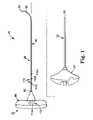
- FIG. 1illustrates components of an intraosseous curable material delivery system in accordance with principles of the present invention
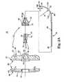
- FIG. 2Ais a cross-sectional, exploded view of a delivery cannula device component of the system of FIG. 1 ;
- FIG. 2Bis a front view of a delivery cannula and hub portions of the device of FIG. 2A ;
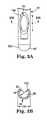
- FIG. 3Ais an enlarged plan view of a distal portion of the delivery cannula of FIG. 2A ;
- FIG. 3Bis a cross-sectional view of the delivery cannula of FIG. 3A ;
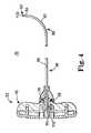
- FIG. 4is a cross-sectional view of the delivery cannula device of FIG. 2A upon final assembly
- FIG. 5is a side plan view of an alternative delivery cannula device in accordance with principles of the present invention.
- FIG. 6Ais a simplified plan view of an intraosseous curable material delivery system employed in a palliative bone procedure in accordance with principles of the present invention
- FIG. 6Bis a cross-sectional view of a portion of the system of FIG. 6A ;
- FIG. 6Cillustrates a final stage of a procedure performed by the system of FIG. 6A ;
- FIG. 6Dis a transverse, sectional view of a vertebral body in combination with a portion of the system of FIG. 6A , illustrating injection of curable material;
- FIG. 6Eis a transverse, sectional view of a vertebral body illustrating various vertebroplasty approach positions available in accordance with principles of the present invention
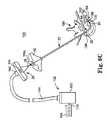
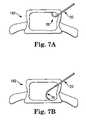
- FIGS. 7A and 7Bare simplified anterior views of a vertebral body, illustrating use of the system in accordance with principles of the present invention.
- FIGS. 8A and 8Bare simplified lateral views of a vertebral body, illustrating use of the system in accordance with principles of the present invention.
- FIG. 1illustrates components of an intraosseous, curable material delivery system 20 according to principles of the present invention.
- the system 20includes an outer guide cannula 22 and a delivery cannula device 26 (referenced generally). Details on the various components are provided below. In general terms, however, a portion of the delivery cannula device 26 is sized to be slidably disposed within the guide cannula 22 that otherwise serves to form and/or locate a desired delivery site within bone. Once positioned, the delivery cannula device 26 is employed to inject a curable, bone stabilizing material into the delivery site.
- the system 20can be used for a number of different procedures, including, for example, vertebroplasty and other bone augmentation procedures in which curable material is delivered to a site within bone, as well as to remove or aspirate material from a site within bone.
- the system 20and in particular the delivery cannula device 26 , is highly useful for delivering a curable material in the form of a bone cement material.
- curable materialwithin the context of the substance that can be delivered by the system/device of the invention described herein is intended to refer to materials (e.g., composites, polymers, and the like) that have a fluid or flowable state or phase and a hardened, solid or cured state or phase.
- Curable materialsinclude, but are not limited to injectable polymethylmethacrylate (PMMA) bone cement, which has a flowable state wherein it can be delivered (e.g., injected) by a cannula to a site and subsequently cures into hardened cement.
- PMMApolymethylmethacrylate
- the system 20further includes a source (not shown) of curable material fluidly coupled to the delivery cannula device 26 .
- the outer guide cannula 22generally enables access of the delivery cannula device 26 to a bone site of interest, and thus can assume a wide variety of forms.
- the guide cannula 22is sized to slidably receive a portion of the delivery cannula device 26 , terminating in an open, distal tip 28 .
- the distal tip 28can further be adapted to facilitate coring of bone tissue, such as when using the guide cannula 22 to form a delivery site within bone.
- an inner diameter surface of the guide cannula 22is highly smoothed to a matte or mirror finish (i.e., RMS range of 4-16).
- the guide cannula 22can further be attached, at a proximal end thereof, to a handle 30 for enhancing a surgeon's ability to manipulate the system 20 .
- the handle 30can be eliminated.
- the delivery cannula device 26is shown in greater detail in FIG. 2A , and generally includes a handle assembly 32 (referenced generally), a hub 34 , and a delivery cannula 36 .
- the hub port 34forms a fluid port and is fluidly connected to the delivery cannula 36 , with the handle assembly 32 retaining the combination hub 34 /delivery cannula 36 .
- the delivery cannula 36is sized to be coaxially, slidably received within the guide cannula 22 ( FIG. 1 ), and is adapted to deliver a curable material injected therein via the hub 34 .
- the handle assembly 32includes, in one embodiment, a handle 40 and a retainer 42 .
- the handle 40is adapted to receive the hub 34 , with the retainer 42 securing the hub 34 (and thus the delivery cannula 36 ) to the handle 40 .
- the handle 40in one embodiment, includes a first section 44 and a second section 46 .
- the first section 44is adapted for snap-fit assembly to the second section 46 , such as by complimentary annular protrusion(s) 48 and grooves 50 .
- the first section 44forms a central passage 52 extending inwardly from an exterior surface 54 thereof.
- the second section 46defines an internal aperture 56 that, upon final assembly of the handle 40 , is aligned with the central passage 52 .
- the aperture 56can assume a variety of forms sized to receive the hub 34 in a nested manner.
- the nested interface between the handle 40 and the hub 34is preferably adapted such that the hub 34 cannot rotate relative to the handle 40 upon final assembly (i.e., the hub 34 /handle 40 interface resists a torque imparted on either component such that rotational movement of the handle 40 results in an identical rotation of the hug 34 /delivery cannula 36 even when the delivery cannula 36 is inserted within a confined surgical site).
- the aperture 56 and the hub 34have corresponding non-symmetrical or non-circular shapes in transverse cross-section.
- the non-circular shape of the aperture 56is characterized by the aperture 56 being defined by a sidewall 58 having a shoulder 60 corresponding with the shape of the hub 34 as described in greater detail below.
- the sidewall 58can assume a variety of other configurations.
- the second section 46forms exterior threads 62 .
- the retainer 42is configured to secure the hub 34 /delivery cannula 36 to the handle 40 , and forms a central opening 64 defining a proximal portion 66 and a distal portion 68 .
- the proximal portion 66forms the central opening 64 to have a diameter slightly greater than that of the hub 34 , along with internal threads 70 sized to threadably engage the exterior threads 62 of the handle 40 .
- the distal portion 68forms the opening 64 to have a diameter approximating an outer diameter of the delivery cannula 36 so as to provide a more rigid connection between the handle assembly 32 and the hub 34 /delivery cannula 36 .
- the handle assembly 32can assume a wide variety of other forms and in some embodiments can be eliminated entirely.
- the hub 34is of a conventional fluid port design and defines a fluid passage 71 and an exterior thread 72 on a proximal end 74 thereof.
- the thread 72is a double start right hand Luer thread including a 5-millimeter lead, although other thread conformations and lead sizes are also acceptable.
- the hub 34is configured to be rotatably “locked” relative to the handle assembly 32 upon final assembly.
- a body of the hub 34forms a generally cylindrical surface 76 a portion of which is flattened in an area 78 , as shown in FIG. 2B .
- the size and shape of the flattened area 78corresponds with the aperture sidewall 58 ( FIG. 2A ) provided with the handle 40 ( FIG. 2A ).
- the hub 34is formed, in one embodiment, of a sterilizable polymeric material.
- the hub 34can be formed of a polylac 717 C acrylonitrile-butadiene-styrene (ABS) copolymer, although other sterilizable polymers and/or copolymers are also acceptable.
- ABSacrylonitrile-butadiene-styrene
- the delivery cannula 36defines a proximal end 80 and a distal end 82 , and forms one or more side orifices 84 adjacent the distal end 80 and in fluid communication with an internal lumen 86 .
- the delivery cannula 36includes a deflectable segment 88 (referenced generally) defining a pre-set curve or bend 90 .
- the deflectable segment 88and in particular the bend 90 , includes or extends from the distal end 82 , and has a shape memory attribute whereby the deflectable segment 88 can be forced from the curved shape (shown in FIG. 2A ) to a substantially straightened shape, and will naturally revert back to the curved shape upon removal of the force.
- the proximal end 80is axially open to the lumen 86 .
- the distal end 82is axially closed to the lumen 86 (i.e., material cannot be axially expelled from the distal end 82 relative to an axis of the lumen 86 ). That is to say, material in the lumen 86 cannot be forced distally therefrom in an axial fashion.
- the distal end 82defines or includes a blunt tip 100 .
- the blunt tip 100defines a hemispherical surface, although other blunt (i.e., curved or curvilinear) shapes or contours are also acceptable.
- the blunt tip surface 100is adapted to provide a non-traumatic surface suitable for accessing, contacting and probing bone or tissue while minimizing the risk of puncture and/or coring of the tissue or damage to the bone.
- the blunt tip 100can have a differing thickness as compared to a remainder of the delivery cannula 36 such as by sintering the distal end 82 to form the blunt tip 100 (when the delivery cannula 36 is initially provided as a continuous tube).
- the blunt tip 100can be formed apart from a remainder of the delivery cannula 36 and subsequently attached to the delivery cannula 36 to form the distal end 82 (e.g., the delivery cannula 36 can include a first tubular body formed of a hardened material along with a second, solid body formed of a softer material attached (e.g., welded) to the tubular body to form the distal end 82 /blunt tip 100 ).
- the delivery cannula 36can include a first tubular body formed of a hardened material along with a second, solid body formed of a softer material attached (e.g., welded) to the tubular body to form the distal end 82 /blunt tip 100 ).
- the side orifice(s) 84is formed adjacent the distal end 82 , extending through a thickness of a sidewall of the delivery cannula 36 .
- a single orifice 84is provided, and is located “opposite” a direction of the bend 90 .
- a direction of the bend 90serves to form the delivery cannula 36 to define an interior bend side 102 and an exterior bend side 104 .
- the side orifice 84is formed along, and is open relative to, the exterior bend side 104 .
- the side orifice 84is offset at least a distance D 1 from the distal end 82 .
- the distance D 1is between 0.05 inches and 0.5 inches, and preferably the distance D 1 is between 0.1 inches and 0.25 inches.
- the side orifice(s) 84is “open” and thus available for dispensing (or aspirating) material. Further, the side orifice(s) 84 provides a radial dispensing or flow direction relative to a longitudinal axis of the delivery cannula 36 .
- the side orifice(s) 84can assume a wide variety of shapes and sizes (relative to an exterior surface of the delivery cannula 36 ).
- the side orifice(s) 84can be oval, circular, curvilinear, etc.
- a chamfered region 106can be formed about the side orifice 84 to eliminate sharp edges along an exterior of the delivery catheter 36 as well as to promote consistent flow of curable material from the side orifice 84 (via the expanding orifice size effectuated by the chamfered region 106 ).
- an orifice length L and width Ware defined.
- the length Lis greater than 0.050 inch, preferably greater than 0.075 inch, and even more preferably greater than 0.100 inch. While the width W of the side orifice 84 may or may not be less than the length L (e.g., on the order of 0.042 inch in one embodiment), the side orifice 84 is properly characterized as being relatively large, especially as compared to conventional bone cement delivery needles that otherwise provide only an axial orifice or opening at the distal tip.
- the delivery cannula 36defines an inside diameter ID (i.e., a diameter of the lumen 86 ).
- the side orifice 84is fluidly connected to the lumen 86 and extends in a radial fashion. With these conventions in mind, in one embodiment, the length L of the side orifice 84 is greater the inside diameter ID of the delivery cannula 36 .
- At least one linear dimension of the side orifice 84is larger than any orifice dimension that could otherwise be achieved were an orifice to be formed at the distal end 82 (i.e., an axially extending orifice). That is to say, an orifice formed at the distal end 82 of the delivery cannula 82 (as is conventionally employed in the bone cement delivery needle art) is limited in size (i.e., diameter) by the inside diameter ID of the delivery cannula 36 .
- the side orifice 84 in accordance with principles of the present inventionis much larger, presenting a distinct advantage when attempting to pass a low viscosity liquid (curable material such as bone cement) there through.
- the delivery cannula 36defines a continuous length between the proximal end 80 and the distal end 82 , with the deflectable segment 88 , and in particular the bend 90 , extending along approximately 25% of the length from the distal end 82 (where the “length” of the delivery cannula 36 is the length of extension from the hub 34 upon final assembly).
- the deflectable segment 88and in particular the bend 90 , extends along between 10%-50% of the length of the delivery cannula 36 as measured from the distal end 82 .
- the deflectable segment 88can be formed to define the bend 90 at a pre-determined radius of curvature R appropriate for the procedure in question.
- the bend 90is J-shaped (approximating at least a 90 degree bend) and defines the radius of curvature R to be less than 1.5 inches, preferably in the range of 0.25-1.5 inches. In one preferred embodiment, the bend 90 defines the radius of curvature R to be approximately 1 inch. Alternatively, and as described in greater detail below, the radius of curvature R can be greater or lesser, depending upon the particular procedure for which the delivery cannula 36 is to be employed.
- the delivery cannula 36is formed of a shape memory metal.
- the delivery cannula 36comprises NitinolTM, a known shape memory alloy of nickel (Ni) and titanium (Ti).
- the bend 90is formed in the delivery cannula 36 by deforming a straight fluid delivery cannula under extreme heat for a prescribed period of time, which pre-sets a curved shape in the delivery cannula 36 .
- the pre-set curve or bend 90is formed in an initially straight cannula by cold working the straight cannula and applying a mechanical stress. Cold working permanently locks a crystalline structure (for example, a partial martensitic crystalline structure) in a portion (i.e., the deflectable segment 88 ) of the cannula, while an unstressed portion remains in, for example, an austenitic structure.
- a crystalline structurefor example, a partial martensitic crystalline structure
- an unstressed portionremains in, for example, an austenitic structure.
- the deflectable segment 88is formed to be resilient and to naturally assume the desired radius of curvature R. In this manner, after the delivery cannula 36 , and in particular the deflectable segment 88 , is flexed to a substantially straightened shape (not shown), upon a subsequent relaxation, the deflectable segment 88 “remembers” the pre-set curved shape and reversibly relaxes/returns to the bend 90 , as described in detail below.
- the delivery cannula 36defines the inside diameter (ID) and an outside diameter (OD).
- the inside diameter IDis in the range of 0.040-0.090 inch, preferably in the range of 0.050-0.080 inch, and more preferably in the range of 0.047-0.067 inch.
- the outside diameter ODis selected to permit the delivery cannula 36 to be co-axially received by the outer guide cannula 22 ( FIG. 1 ).
- the outside diameter ODis in the range of 0.030-0.10 inch, preferably not greater than 0.090 inch, more preferably in the range of 0.060-0.090 inch, and more preferably in the range of 0.072-0.082 inch.
- the delivery cannula 36is of a reduced outer diameter and thickness as compared to available bone cement delivery needles (e.g., the curved needle available with the OSTEO-RXTM product line has an outside diameter of 0.092 inch and a wall thickness of 0.027 inch).
- the curved needle available with the OSTEO-RXTM product linehas an outside diameter of 0.092 inch and a wall thickness of 0.027 inch.
- an exemplary delivery catheterwas constructed in accordance with principles of the present invention having an outside diameter of approximately 0.077 inch and a wall thickness of 0.015 inch, and was found to be highly suitable for performing a vertebroplasty procedure. This represents a distinct advancement not heretofore available to surgeons.
- the delivery cannula 36includes indicia 110 (reference generally) adjacent the proximal end 80 .
- the indicia 110is indicative of a location of the distal end 82 relative to the distal tip 28 of the guide cannula 22 upon insertion of the delivery cannula 36 within the guide cannula 22 .
- the indicia 110can include first, second, and third depth markings 110 a , 110 b , 110 c .
- a longitudinal location of the first depth marking 110 a relative to the distal end 82 (when the delivery cannula 36 is forced to a substantially straightened state)is commensurate with a length of the guide cannula 22 in combination with the handle 30 (where provided).
- the first depth marking 110 ais located at a linear distance from the distal end 82 such that upon insertion of the delivery cannula 36 within the guide cannula 22 (otherwise forcing the delivery cannula 36 to a substantially straightened state), when the distal end 82 is at or even with the distal tip 28 of the guide cannula 22 , the first depth marking 110 a will be proximally adjacent or aligned with (and visible relative to) a proximal side of the handle 30 .
- a usercan quickly and easily have visual confirmation that the distal end 82 is within the guide cannula 22 .
- the second and third depth markings 110 b , 110 care proximally spaced from the first depth marking 110 a at known increments (e.g., 0.5 cm, 1.0 cm, etc.) that represent length of distal extension of the distal end 82 relative to the distal tip 28 .
- the second depth marking 110 bis longitudinally spaced (proximally) a distance of 0.5 cm from the first depth marking 110 a and the third depth marking 110 c is spaced 0.5 cm from the second depth marking 110 b
- a usercan visually confirm (from a location away from the surgical site and outside of the patient) that an approximately 0.5 cm length of the delivery cannula 36 is extending distal the distal tip 28 of the guide cannula 22 .
- the third marking 110 cis aligned with the proximal side of the handle 30 , an approximately 1.0 cm length of the delivery cannula 36 is exposed distal the distal tip 28 .
- the indicial 110can assume a wide variety of forms differing from that shown in FIG. 1 , and in some embodiments can be eliminated.
- assembly of the delivery cannula device 26includes first securing the hub 34 to the delivery cannula 36 .
- the hub 34is overmolded onto the delivery cannula 36 .
- a support body 112is secured to the delivery cannula 36 adjacent the proximal end 80 (referenced generally) prior to forming/overmolding the hub 34 .
- the support body 112is preferably a rigid material amenable to affixment to the delivery cannula 36 material (e.g., where the delivery cannula 36 is formed of Nitinol, the support body 112 can also be formed of Nitinol as thus easily welded to the delivery cannula 36 ).
- the support body 112can assume a variety of shapes and sizes, but in one embodiment, is rectangular (a thickness on the order of 0.035 inch, width on the order of 0.05 inch, and a length on the order of 0.2 inch, although other dimensions are equally acceptable) so that when applied to the otherwise circular (in transverse cross-section) delivery cannula 36 , the support body 112 provides flat surfaces onto which the hub 34 is overmolded.
- This flat surface area interfaceovertly resists “slipping” of the hub 34 relative to the delivery cannula 36 and vice-versa in response to a tensile, compressive, and/or torsional force(s) placed on either component.
- a tensile, compressive, and/or torsional force(s) placed on either componentFor example, in instances where the distal end 82 of the delivery cannula 36 is inserted or lodged within bodily material (e.g., bone or tissue) at a surgical site and a proximal pulling force is placed on the hub 34 (for example, via the handle 40 ), the delivery cannula 36 will not detach from the hub 34 even though the distal end 82 “resists” proximal movement (due to lodgment within the bodily material).
- bodily materiale.g., bone or tissue
- a rotational or torsional force placed upon the hub 34will consistently translate onto the delivery cannula 36 via the hub 34 /support piece 112 interface regardless of whether the distal end 82 “resists” rotational movement due to surgical site interactions.
- the support body 112can be omitted and is not a necessary element.
- the hub 34is mounted within the handle assembly 32 as previously described.
- the hub 34is nested within the aperture 56 of the handle 40 , and the retainer 42 is coaxially disposed over the hub 34 /delivery cannula 36 and secured (e.g., threadably engaged) to the handle 40 .
- the hub 34is oriented relative to delivery cannula 36 such that the flattened area 78 of the hub 34 “faces” a spatial direction of the bend 90 .
- the previously described configuration of the handle assembly 32thus dictates that upon assembly of the hub 34 to the handle 40 , the bend 90 will also extend in a known spatial direction relative to the handle 40 .
- a spatial direction of the bend 90 relative to the handle 40can be visually determined following mounting of the hub 34 thereto.
- the handle assembly 32further includes directional indicia 114 (referenced generally) along an exterior of the handle 40 that provides a user with an indication of the bend 90 direction relative to the handle 40 .
- the directional indicia 114includes an arrow 114 a “pointing” at the direction of the bend 90 .
- the directional indicia 114can be applied at various locations along the handle 40 such as on both major faces (one of which is visible in FIG. 1 ) as well as a proximal end thereof, and can assume a variety of forms. In other embodiments, the directional indicia 114 can be eliminated. Regardless, following mounting of the hub 34 to the handle assembly 32 , the delivery cannula device 26 can be used to deliver a curable material into bone.
- FIG. 5illustrates portions of another embodiment delivery cannula device 120 in accordance with principles of the present invention.
- the delivery cannula device 120includes a delivery cannula 122 that extends a length between a proximal end 124 and a distal end 126 , and a hub 128 coupled to the proximal end 124 .
- the delivery cannula 122is similar to the delivery cannula 36 ( FIG.
- the delivery cannula 122includes a deflectable segment 132 forming a pre-set curve 134 , similar to previous embodiments.
- a distal-most side orifice 130 ais offset the distance D 1 from the distal end 116 .
- the distance D 1is, in one embodiment, in the range of 0.05-0.5 inch, preferably in the range of 0.1-0.25 inch.
- a longitudinal spacing between the remaining side orifices 130 proximal the distal-most side orifice 130 acan vary.
- the second side orifice 130 bdefines a smaller sized opening as compared to the distal-most side orifice 130 a
- the third side orifice 130 cis smaller than the second side orifice 130 b . This reduction in side orifice size proximal the distal end 126 promotes consistent distribution of curable material otherwise being forced through the delivery cannula 122 .
- the side orifices 130While three of the side orifices 130 are shown, other configurations are also acceptable. For example, multiple side orifices (i.e., more than three side orifices) can be formed longitudinally along the length of the delivery cannula 122 , and in addition, the side orifices 130 can include more than one longitudinally aligned series of side orifices. In an exemplary embodiment, the side orifices 130 that are visible in FIG. 5 are matched by another column of longitudinally aligned side orifices formed on an opposing side of the delivery cannula 122 (and therefore not visible in the view of FIG. 5 ). Aspects of the present invention provide for the side orifices 130 to define circular side orifices, non-circular side orifices, or a set of circular and non-circular side orifices.
- the pre-set curve 134is curved away from a central axis C of the delivery cannula 122 such that the curvature of the pre-set curve 134 is less than the radius of curvature R of the pre-set curve 90 ( FIG. 2A ) previously described, thus illustrating another embodiment in accordance with principles of the present invention.
- the side orifices 130are depicted as formed along the pre-set curve 134 , in another embodiment at least one of the side orifices 130 is formed proximal the pre-set curve 134 .
- FIG. 6Aillustrates an intraosseous curable material delivery system 150 according to one embodiment of the present invention, employed to perform a vertebroplasty procedure.
- the system 150includes the outer guide cannula 22 , the delivery cannula device 26 , a curable material source 152 fluidly coupled to the delivery cannula device 26 , and a controller 154 coupled to at least the curable material source 152 .
- the curable material source 152includes, in one embodiment, a canister 160 containing a curable material as previously described, and tubing 164 extending from the canister 160 to the handle assembly 30 of the delivery cannula device 26 .
- the tubing 164terminates at a fitting 166 configured to removably attach to the hub 34 .
- the fitting 166is configured to fit within the passage 52 of the handle 40 and removably couple to the hub 34 .
- the fitting 166threads onto a Luer thread defined by the hub 34 .
- the fitting 166snap-fits over the hub 34 .
- a wide variety of other attachment configurationsare also available.
- the controller 154can assume any form known in the art and is coupled to the curable material source 152 .
- the controller 154controls a mass flow and a mass flow rate (i.e., a fluid delivery rate) of curable material from the canister 160 to the delivery cannula device 26 .
- the controller 154can include a variety of actuators (e.g., switch(es), foot pedal(s), etc.) affording a user the ability to remotely control liquid flow into the delivery cannula 36 .
- actuatorse.g., switch(es), foot pedal(s), etc.
- manual controlcan be employed such that the controller 154 can be eliminated.
- the outer guide cannula 22is located at a desired delivery site within bone.
- the outer guide cannula 22is introduced into a vertebra 180 , preferably at a pedicle 182 .
- the vertebra 180includes a vertebral body 184 defining a vertebral wall 186 surrounding bodily material (e.g., cancellous bone, blood, marrow, and other soft tissue) 188 .
- the pedicle 182extends from the vertebral body 184 and surrounds a vertebral foramen 190 .
- the pedicle 182is attached posteriorly to the vertebral body 184 and together they comprise the vertebrae 180 and form the walls of the vertebral foramen 190 .
- the intraosseous system 150is suitable for accessing a variety of bone sites.
- a vertebra 180is illustrated, it is to be understood that other bone sites can be accessed by the system 150 (i.e., femur, long bones, ribs, sacrum, etc.).
- the outer guide cannula 22forms an access path to a delivery site 192 (or forms the delivery site 192 ) through the pedicle 182 into the bodily material 188 .
- the outer guide cannula 22has been driven through the pedicle 182 via a transpedicular approach.
- the transpedicular approachlocates the outer guide cannula 22 between the mammillary process and the accessory process of the pedicle 182 .
- the outer guide cannula 22provides access to the delivery site 192 at the open, distal tip 28 .
- the outer guide cannula 22can similarly perform a coring-like operation, forming an enlarged opening within bone.
- the delivery cannula 36is slidably inserted/distally advanced within the outer guide cannula 22 .
- the distal end 82 of the delivery cannula 36is poised at the distal tip 28 of the outer guide cannula 22 .
- Approximate alignment of the first depth marking 110 a with the handle 30provides a user with visual confirmation (at a point outside of the patient) of the distal end 82 positioning relative to the outer guide cannula 22 distal tip 28 .
- the delivery cannula 36Prior to further distal movement, the delivery cannula 36 is entirely within the outer guide cannula 22 such that the deflectable segment 88 ( FIG. 2A ) of the delivery cannula 36 is constrained (i.e., flexed) to a substantially straightened shape that generally conforms to a shape of the outer guide cannula 22 .
- This relationshipis shown more clearly in FIG. 6B whereby a force is effectively imparted by the guide cannula 22 onto the deflectable segment 88 due to the radius of curvature R ( FIG. 2A ) defined by the deflectable segment 88 in a “natural” state being larger than an inner diameter of the guide cannula 22 .
- This interactionessentially “removes” the pre-set curvature of the bend 90 ( FIG. 2A ), forcing or rendering the deflectable segment 88 to a substantially straightened state (it being understood that because an inner diameter of the guide cannula 22 is greater than the outside diameter of the delivery cannula 36 , the deflectable segment 88 will continue to have a slight curvature within in the guide cannula 22 ; thus, “substantially straightened” is in reference to the delivery cannula 36 being substantially, but not necessarily entirely, linear).
- the delivery cannula 36prior to interaction with the delivery site 192 ( FIG. 6A ), the delivery cannula 36 is flexed in a substantially straight, non-curved orientation within the outer guide cannula 22 .
- the delivery cannula device 26and in particular the delivery cannula 36 , is then distally advanced within the guide cannula 22 as shown in FIG. 6C .
- the delivery cannula 36is distally maneuvered such that at least a portion of the deflectable segment 88 extends beyond the open tip 28 of the guide cannula 22 and into the delivery site 192 .
- the now unrestrained portion of the deflectable segment 88naturally deflects laterally (from the substantially straight shape described above) upon exiting the guide catheter 22 , reverting to the pre-set curvature of the bend 90 previously described due to the shape memory characteristic.
- the usercan visually confirm a length of distal extension of the delivery catheter 36 from the guide catheter 22 via a longitudinal positioning of the indicia 110 b or 110 c (the indicia 110 c being visible in FIG. 6C ) relative to the handle 30 .
- the directional indicia 114indicates to a user (at a point outside of the patient) a spatial direction of the bend 90 within the delivery site 192 relative to a spatial position of the handle 40 .
- the blunt tip 100 of the distal end 82is hemispherically shaped (or other non-sharpened or blunt shape) and thus atraumatic relative to contacted tissue/bone.
- the blunt tip 100can contact and/or probe the vertebral wall 186 with a minimum of risk in puncturing or coring the vertebral body 184 .
- the blunt tip 100offers an advantage over the conventional, sharp-edged bone cement delivery needles, and does not require a separate wire to prevent coring as is otherwise necessary with available curved needles.
- the side orifice 84is offset from the distal end 82 and is, therefore, available to deliver curable material into, and remove bodily material from, the delivery site 192 .
- the side orifice 84can eject curable material radially from, and aspirate bodily material into, the delivery cannula 36 , even when the distal end 82 is pressed against a surface, such as an interior wall of the vertebral body 184 .
- the fluid source 152is then operated (e.g., via the controller 154 ) to deliver a curable material (not shown) to the delivery cannula 36 via the hub 34 .
- Curable material entering the delivery cannula 36is forced through the lumen 86 ( FIG. 2A ) towards the side orifice 84 .
- the curable materialis then dispensed/injected from the delivery cannula 36 in a radial fashion from the side orifice(s) 84 and into the delivery site 192 in a cloud-like pattern 194 .
- the delivery site 192can be aspirated by replacing the curable material source 152 ( FIG. 6A ) with a vacuum source (not shown).
- FIG. 6Aillustrates a fracture 196 in the vertebral body wall 186 .
- Vertebroplastyis a common solution to such vertebral fractures, with the accepted repair technique entailing positioning the distal end 82 at or “facing” the fracture 196 to ensure that the curable material is dispensed in relatively close proximity thereto.
- this preferred approachresults in the curable material being injected directly toward the fracture 196 .
- the distal end 82is still “facing” the fracture 196 , yet the injected curable material cloud 194 is not forced directly toward the fracture 196 .
- the curable material cloud 194indirectly reaches the fracture 196 with minimal retained propulsion force such that the curable material cloud 194 is unlikely to forcibly “leak” through the fracture 196 .
- the delivery site 192is, as a whole, still filled with the curable material cloud 194 to effectuate the desired repair.
- an entirety of the delivery site 192is accessible by the delivery cannula 36 .
- the system 150can effectuate a vertebroplasty procedure from a left posterior lateral approach, or to right or left anterior lateral approaches as shown in FIG. 6E .
- a desired volume of the curable materialis delivered entirely through the delivery cannula 36 .
- the delivery cannula 36is disconnected from the curable material source 152 and removed from the guide cannula 22 .
- the curable material source 152is then fluidly connected to the guide cannula 22 (e.g., the fitting 166 is fluidly connected to a corresponding fluid port/hub provided with the handle 30 ) and then operated to inject a second volume of curable material to the delivery site 192 via the guide cannula 22 .
- a clinician operating the intraosseous system 150extends a portion of the pre-set curve 90 into the delivery site 192 otherwise defined within bone.
- a subsequent rotation of the delivery cannula 36rotates a spatial position of the side orifice 84 relative to the delivery site 192 , thus accessing multiple planes of the delivery site 192 with only one “stick” of the outer guide cannula 22 .
- FIGS. 7A-8Bgenerally illustrate ( FIGS. 7A and 7B from an anterior perspective; FIGS.
- a direction of the bend defined by the delivery cannula 36is not necessarily perpendicular to the plane of the page, such that the bend may not be fully evident in each view.
Landscapes
- Health & Medical Sciences (AREA)
- Life Sciences & Earth Sciences (AREA)
- Orthopedic Medicine & Surgery (AREA)
- Surgery (AREA)
- Medical Informatics (AREA)
- General Health & Medical Sciences (AREA)
- Biomedical Technology (AREA)
- Heart & Thoracic Surgery (AREA)
- Nuclear Medicine, Radiotherapy & Molecular Imaging (AREA)
- Molecular Biology (AREA)
- Animal Behavior & Ethology (AREA)
- Engineering & Computer Science (AREA)
- Public Health (AREA)
- Veterinary Medicine (AREA)
- Surgical Instruments (AREA)
- Materials For Medical Uses (AREA)
- Prostheses (AREA)
- Infusion, Injection, And Reservoir Apparatuses (AREA)
- Coating Apparatus (AREA)
Abstract
Description
Claims (33)
Priority Applications (23)
| Application Number | Priority Date | Filing Date | Title |
|---|---|---|---|
| US11/282,102US7713273B2 (en) | 2005-11-18 | 2005-11-18 | Device, system and method for delivering a curable material into bone |
| AT06255900TATE493086T1 (en) | 2005-11-18 | 2006-11-17 | DEVICE AND SYSTEM FOR DELIVERING A CURED MATERIAL INTO A BONE |
| PT06255900TPT1787592E (en) | 2005-11-18 | 2006-11-17 | Device and system for delivering a curable material into bone |
| DK06255900.0TDK1787592T3 (en) | 2005-11-18 | 2006-11-17 | Device and system for administering a curable material to a bone |
| ES06255900TES2357496T3 (en) | 2005-11-18 | 2006-11-17 | DEVICE AND SYSTEM FOR ADMINISTRATION OF A CURABLE MATERIAL IN A BONE. |
| CA2568374ACA2568374C (en) | 2005-11-18 | 2006-11-17 | Device, system and method for delivering a curable material into bone |
| PL06255900TPL1787592T3 (en) | 2005-11-18 | 2006-11-17 | Device and system for delivering a curable material into bone |
| DE602006019192TDE602006019192D1 (en) | 2005-11-18 | 2006-11-17 | Device and system for delivering a hardenable material into a bone |
| AU2006236104AAU2006236104B2 (en) | 2005-11-18 | 2006-11-17 | Device, system and method for delivering a curable material into bone |
| EP06255900AEP1787592B1 (en) | 2005-11-18 | 2006-11-17 | Device and system for delivering a curable material into bone |
| NZ551392ANZ551392A (en) | 2005-11-18 | 2006-11-17 | Device, system and method for delivering a curable material into bone |
| IL179394AIL179394A (en) | 2005-11-18 | 2006-11-19 | Device, system and method for delivering a curable material into bone |
| NO20065306ANO20065306L (en) | 2005-11-18 | 2006-11-20 | Apparatus, system and method for delivering a curable material into bone |
| BRPI0605167-7ABRPI0605167A (en) | 2005-11-18 | 2006-11-21 | device, system and method for distributing a curable material within the bone |
| US11/704,139US7799035B2 (en) | 2005-11-18 | 2007-02-08 | Device, system and method for delivering a curable material into bone |
| US12/633,358US8529576B2 (en) | 2005-11-18 | 2009-12-08 | Device, system and method for delivering a curable material into bone |
| US12/634,366US8128633B2 (en) | 2005-11-18 | 2009-12-09 | Device, system, and method for forming a cavity in and delivering a curable material into bone |
| US29/358,542USD669168S1 (en) | 2005-11-18 | 2010-03-29 | Vertebral augmentation needle |
| CY20111100328TCY1112403T1 (en) | 2005-11-18 | 2011-03-28 | APPLIANCE, SYSTEM AND METHOD FOR SUPPLYING RESTRICTED BONE |
| US13/483,899US8690884B2 (en) | 2005-11-18 | 2012-05-30 | Multistate-curvature device and method for delivering a curable material into bone |
| US14/223,064US9358059B2 (en) | 2005-11-18 | 2014-03-24 | Device and method for delivering a curable material into bone |
| US15/076,221US9795429B2 (en) | 2005-11-18 | 2016-03-21 | Device and method for removing bodily material |
| US15/699,084US10314633B2 (en) | 2005-11-18 | 2017-09-08 | Shape memory device with temperature-dependent deflectable segment and methods of positioning a shape memory device within a bone structure |
Applications Claiming Priority (1)
| Application Number | Priority Date | Filing Date | Title |
|---|---|---|---|
| US11/282,102US7713273B2 (en) | 2005-11-18 | 2005-11-18 | Device, system and method for delivering a curable material into bone |
Related Child Applications (2)
| Application Number | Title | Priority Date | Filing Date |
|---|---|---|---|
| US11/704,139Continuation-In-PartUS7799035B2 (en) | 2005-11-18 | 2007-02-08 | Device, system and method for delivering a curable material into bone |
| US29/358,542Continuation-In-PartUSD669168S1 (en) | 2005-11-18 | 2010-03-29 | Vertebral augmentation needle |
Publications (2)
| Publication Number | Publication Date |
|---|---|
| US20070118142A1 US20070118142A1 (en) | 2007-05-24 |
| US7713273B2true US7713273B2 (en) | 2010-05-11 |
Family
ID=37762223
Family Applications (1)
| Application Number | Title | Priority Date | Filing Date |
|---|---|---|---|
| US11/282,102Active2026-03-09US7713273B2 (en) | 2005-11-18 | 2005-11-18 | Device, system and method for delivering a curable material into bone |
Country Status (15)
| Country | Link |
|---|---|
| US (1) | US7713273B2 (en) |
| EP (1) | EP1787592B1 (en) |
| AT (1) | ATE493086T1 (en) |
| AU (1) | AU2006236104B2 (en) |
| BR (1) | BRPI0605167A (en) |
| CA (1) | CA2568374C (en) |
| CY (1) | CY1112403T1 (en) |
| DE (1) | DE602006019192D1 (en) |
| DK (1) | DK1787592T3 (en) |
| ES (1) | ES2357496T3 (en) |
| IL (1) | IL179394A (en) |
| NO (1) | NO20065306L (en) |
| NZ (1) | NZ551392A (en) |
| PL (1) | PL1787592T3 (en) |
| PT (1) | PT1787592E (en) |
Cited By (32)
| Publication number | Priority date | Publication date | Assignee | Title |
|---|---|---|---|---|
| US20070197971A1 (en)* | 2006-02-22 | 2007-08-23 | Krueger John A | Curable material delivery device with a rotatable supply section |
| US20070198023A1 (en)* | 1997-08-13 | 2007-08-23 | Kyphon Inc. | Systems and methods for injecting flowable materials into bones |
| US20100087828A1 (en)* | 2005-11-18 | 2010-04-08 | Krueger John A | Device, system and method for delivering a curable material into bone |
| US20110125272A1 (en)* | 2009-11-20 | 2011-05-26 | Knee Creations, Llc | Bone-derived implantable devices for subchondral treatment of joint pain |
| US20120029334A1 (en)* | 2010-07-30 | 2012-02-02 | Tegg Troy T | Catheter with a mechanism for omni-directional deflection of a catheter shaft |
| US8690884B2 (en) | 2005-11-18 | 2014-04-08 | Carefusion 2200, Inc. | Multistate-curvature device and method for delivering a curable material into bone |
| US8795369B1 (en) | 2010-07-16 | 2014-08-05 | Nuvasive, Inc. | Fracture reduction device and methods |
| US8814873B2 (en) | 2011-06-24 | 2014-08-26 | Benvenue Medical, Inc. | Devices and methods for treating bone tissue |
| WO2014130231A1 (en) | 2013-02-21 | 2014-08-28 | Carefusion 2200, Inc. | Intravertebral tissue ablation device and method |
| US8821504B2 (en) | 2009-11-20 | 2014-09-02 | Zimmer Knee Creations, Inc. | Method for treating joint pain and associated instruments |
| US8864768B2 (en) | 2009-11-20 | 2014-10-21 | Zimmer Knee Creations, Inc. | Coordinate mapping system for joint treatment |
| US8882836B2 (en) | 2005-08-16 | 2014-11-11 | Benvenue Medical, Inc. | Apparatus and method for treating bone |
| US8894658B2 (en) | 2009-11-10 | 2014-11-25 | Carefusion 2200, Inc. | Apparatus and method for stylet-guided vertebral augmentation |
| US8906032B2 (en) | 2009-11-20 | 2014-12-09 | Zimmer Knee Creations, Inc. | Instruments for a variable angle approach to a joint |
| WO2015053987A1 (en) | 2013-10-09 | 2015-04-16 | Carefusion 2200, Inc. | Systems for balloon-aided vertebral augmentation |
| US9033987B2 (en) | 2009-11-20 | 2015-05-19 | Zimmer Knee Creations, Inc. | Navigation and positioning instruments for joint repair |
| US9095393B2 (en) | 2012-05-30 | 2015-08-04 | Carefusion 2200, Inc. | Method for balloon-aided vertebral augmentation |
| US9119639B2 (en) | 2011-08-09 | 2015-09-01 | DePuy Synthes Products, Inc. | Articulated cavity creator |
| US9259257B2 (en) | 2009-11-20 | 2016-02-16 | Zimmer Knee Creations, Inc. | Instruments for targeting a joint defect |
| US20160045240A1 (en)* | 2007-09-28 | 2016-02-18 | DePuy Synthes Products, Inc. | Balloon With Shape Control For Spinal Procedures |
| US20160051306A1 (en)* | 2014-08-20 | 2016-02-25 | Kyphon Sarl | Surgical instrument with graduated markings correlating to angulation |
| US9271835B2 (en) | 2009-11-20 | 2016-03-01 | Zimmer Knee Creations, Inc. | Implantable devices for subchondral treatment of joint pain |
| US9393061B2 (en) | 2014-03-17 | 2016-07-19 | Stryker Corporation | Method for balloon-assisted augmentation and fusion of adjacent vertebral bodies |
| US20160228131A1 (en)* | 2013-10-15 | 2016-08-11 | Stryker Corporation | Device for creating a void space in a living tissue, the device including a handle with a control knob that can be set regardless of the orientation of the handle |
| US9439693B2 (en) | 2013-02-01 | 2016-09-13 | DePuy Synthes Products, Inc. | Steerable needle assembly for use in vertebral body augmentation |
| US9532884B2 (en) | 2011-07-14 | 2017-01-03 | Nlt Spine Ltd. | Laterally deflectable implant |
| US9717544B2 (en) | 2009-11-20 | 2017-08-01 | Zimmer Knee Creations, Inc. | Subchondral treatment of joint pain |
| US10085783B2 (en) | 2013-03-14 | 2018-10-02 | Izi Medical Products, Llc | Devices and methods for treating bone tissue |
| US10888364B2 (en) | 2018-01-02 | 2021-01-12 | Medtronic Holding Company Sarl | Scoop cannula with deflectable wings |
| US11364062B2 (en) | 2016-08-18 | 2022-06-21 | Spinal Elements, Inc. | Material delivery surgical device |
| US11439432B2 (en)* | 2020-04-09 | 2022-09-13 | Spinal Generations, Llc | Handle attachment for fluid delivery needle and method of use thereof |
| US11849986B2 (en) | 2019-04-24 | 2023-12-26 | Stryker Corporation | Systems and methods for off-axis augmentation of a vertebral body |
Families Citing this family (63)
| Publication number | Priority date | Publication date | Assignee | Title |
|---|---|---|---|---|
| US7258690B2 (en) | 2003-03-28 | 2007-08-21 | Relievant Medsystems, Inc. | Windowed thermal ablation probe |
| US6907884B2 (en) | 2002-09-30 | 2005-06-21 | Depay Acromed, Inc. | Method of straddling an intraosseous nerve |
| US8361067B2 (en) | 2002-09-30 | 2013-01-29 | Relievant Medsystems, Inc. | Methods of therapeutically heating a vertebral body to treat back pain |
| US8613744B2 (en) | 2002-09-30 | 2013-12-24 | Relievant Medsystems, Inc. | Systems and methods for navigating an instrument through bone |
| US8808284B2 (en) | 2008-09-26 | 2014-08-19 | Relievant Medsystems, Inc. | Systems for navigating an instrument through bone |
| ES2545328T3 (en) | 2003-03-14 | 2015-09-10 | Depuy Spine, Inc. | Bone cement hydraulic injection device in percutaneous vertebroplasty |
| US8066713B2 (en) | 2003-03-31 | 2011-11-29 | Depuy Spine, Inc. | Remotely-activated vertebroplasty injection device |
| US8415407B2 (en) | 2004-03-21 | 2013-04-09 | Depuy Spine, Inc. | Methods, materials, and apparatus for treating bone and other tissue |
| US8579908B2 (en) | 2003-09-26 | 2013-11-12 | DePuy Synthes Products, LLC. | Device for delivering viscous material |
| CN101065080B (en) | 2004-07-30 | 2021-10-29 | 德普伊新特斯产品有限责任公司 | Materials and Instruments for Manipulating Bone and Other Tissues |
| US9381024B2 (en) | 2005-07-31 | 2016-07-05 | DePuy Synthes Products, Inc. | Marked tools |
| US9918767B2 (en) | 2005-08-01 | 2018-03-20 | DePuy Synthes Products, Inc. | Temperature control system |
| US8360629B2 (en) | 2005-11-22 | 2013-01-29 | Depuy Spine, Inc. | Mixing apparatus having central and planetary mixing elements |
| US7922690B2 (en)* | 2006-02-22 | 2011-04-12 | Michael Plishka | Curable material delivery device |
| US20070270876A1 (en)* | 2006-04-07 | 2007-11-22 | Yi-Chen Kuo | Vertebra bone cement introduction system |
| US20070255231A1 (en)* | 2006-04-27 | 2007-11-01 | Sdgi Holdings, Inc. | Vented directional delivery cannula with openings of different shape for use with flowable materials and method for use thereof |
| AU2007297097A1 (en) | 2006-09-14 | 2008-03-20 | Depuy Spine, Inc. | Bone cement and methods of use thereof |
| US8950929B2 (en) | 2006-10-19 | 2015-02-10 | DePuy Synthes Products, LLC | Fluid delivery system |
| US9510885B2 (en) | 2007-11-16 | 2016-12-06 | Osseon Llc | Steerable and curvable cavity creation system |
| US20090131886A1 (en) | 2007-11-16 | 2009-05-21 | Liu Y King | Steerable vertebroplasty system |
| US20090131867A1 (en) | 2007-11-16 | 2009-05-21 | Liu Y King | Steerable vertebroplasty system with cavity creation element |
| JP6017759B2 (en) | 2007-12-21 | 2016-11-02 | スミス アンド ネフュー インコーポレーテッドSmith & Nephew,Inc. | Cannula |
| FR2926997B1 (en)* | 2008-02-04 | 2012-06-29 | Bernard Hertzog | SOFT FLEXIBLE NEEDLES FOR SKIN INJECTION WITHOUT PAIN |
| ITVR20080067A1 (en)* | 2008-06-11 | 2009-12-12 | Tecres Spa | DEVICE FOR SURGICAL USE |
| EP2140824B1 (en) | 2008-07-01 | 2016-06-08 | Biedermann Technologies GmbH & Co. KG | Cannulated bone anchor with plug member and tool for inserting the plug member into the bone anchor |
| CA2737374C (en) | 2008-09-26 | 2017-03-28 | Relievant Medsystems, Inc. | Systems and methods for navigating an instrument through bone |
| US10028753B2 (en) | 2008-09-26 | 2018-07-24 | Relievant Medsystems, Inc. | Spine treatment kits |
| US8702677B2 (en)* | 2008-10-31 | 2014-04-22 | Warsaw Orthopedic, Inc. | Device and method for directional delivery of a drug depot |
| EP2416721B1 (en)* | 2009-04-09 | 2013-07-10 | Synthes GmbH | Minimally invasive spine augmentation and stabilization system |
| US20100298832A1 (en) | 2009-05-20 | 2010-11-25 | Osseon Therapeutics, Inc. | Steerable curvable vertebroplasty drill |
| ES2552380T3 (en)* | 2009-07-01 | 2015-11-27 | Biedermann Technologies Gmbh & Co. Kg | Instruments for use with a bone anchor with closure element |
| US8715223B2 (en)* | 2009-07-22 | 2014-05-06 | Warsaw Orthopedic, Inc. | Device and method for delivery of a drug depot near the nerve |
| US8226657B2 (en)* | 2009-11-10 | 2012-07-24 | Carefusion 207, Inc. | Systems and methods for vertebral or other bone structure height restoration and stabilization |
| US9125671B2 (en) | 2010-04-29 | 2015-09-08 | Dfine, Inc. | System for use in treatment of vertebral fractures |
| WO2012048187A2 (en)* | 2010-10-07 | 2012-04-12 | Benvenue Medical, Inc. | Devices and methods for injecting fluid into the body |
| US8771276B2 (en) | 2010-12-01 | 2014-07-08 | Carefusion 2200, Inc. | Systems and methods for forming a cavity in, and delivering curable material into, bone |
| FR2982492B1 (en)* | 2011-11-10 | 2014-10-17 | Alcora | INJECTION VECTOR FOR A VISCOELASTIC FILLING PRODUCT |
| AU2012362524B2 (en) | 2011-12-30 | 2018-12-13 | Relievant Medsystems, Inc. | Systems and methods for treating back pain |
| US10588691B2 (en) | 2012-09-12 | 2020-03-17 | Relievant Medsystems, Inc. | Radiofrequency ablation of tissue within a vertebral body |
| WO2014071161A1 (en) | 2012-11-05 | 2014-05-08 | Relievant Medsystems, Inc. | System and methods for creating curved paths through bone and modulating nerves within the bone |
| US9724151B2 (en) | 2013-08-08 | 2017-08-08 | Relievant Medsystems, Inc. | Modulating nerves within bone using bone fasteners |
| US9808237B2 (en) | 2013-09-26 | 2017-11-07 | Depuy Mitek, Llc | Methods and devices for passing sutures around anatomical structures |
| US9968373B1 (en)* | 2014-02-21 | 2018-05-15 | Surgentec, Llc | Handles for needle assemblies |
| US10080877B2 (en) | 2014-07-25 | 2018-09-25 | Warsaw Orthopedic, Inc. | Drug delivery device and methods having a drug cartridge |
| US9775978B2 (en) | 2014-07-25 | 2017-10-03 | Warsaw Orthopedic, Inc. | Drug delivery device and methods having a retaining member |
| CN104382642A (en)* | 2014-11-06 | 2015-03-04 | 广州军区广州总医院 | Pedicle screw path infusion device and pedicle screw path local reinforcing assembly |
| CN104921802A (en)* | 2015-07-07 | 2015-09-23 | 创辉医疗器械江苏有限公司 | Guide mechanism used for orthopedic operation |
| US10076650B2 (en) | 2015-11-23 | 2018-09-18 | Warsaw Orthopedic, Inc. | Enhanced stylet for drug depot injector |
| USD802756S1 (en) | 2016-06-23 | 2017-11-14 | Warsaw Orthopedic, Inc. | Drug pellet cartridge |
| JP2019534130A (en) | 2016-10-27 | 2019-11-28 | ディーファイン,インコーポレイティド | Articulated osteotome with cement delivery channel |
| US10434261B2 (en) | 2016-11-08 | 2019-10-08 | Warsaw Orthopedic, Inc. | Drug pellet delivery system and method |
| CA3041114A1 (en) | 2016-11-28 | 2018-05-31 | Dfine, Inc. | Tumor ablation devices and related methods |
| US10470781B2 (en) | 2016-12-09 | 2019-11-12 | Dfine, Inc. | Medical devices for treating hard tissues and related methods |
| EP4480518A3 (en)* | 2016-12-19 | 2025-03-05 | New World Medical, Inc. | Ocular treatment devices |
| US10660656B2 (en) | 2017-01-06 | 2020-05-26 | Dfine, Inc. | Osteotome with a distal portion for simultaneous advancement and articulation |
| US11937864B2 (en) | 2018-11-08 | 2024-03-26 | Dfine, Inc. | Ablation systems with parameter-based modulation and related devices and methods |
| AU2020346827A1 (en) | 2019-09-12 | 2022-03-31 | Relievant Medsystems, Inc. | Systems and methods for tissue modulation |
| US11986229B2 (en) | 2019-09-18 | 2024-05-21 | Merit Medical Systems, Inc. | Osteotome with inflatable portion and multiwire articulation |
| CN111870347B (en)* | 2020-09-04 | 2023-03-14 | 北京铸正机器人有限公司 | Operation route guider under C type arm |
| US12082876B1 (en) | 2020-09-28 | 2024-09-10 | Relievant Medsystems, Inc. | Introducer drill |
| EP4268150A4 (en) | 2020-12-22 | 2024-12-18 | Relievant Medsystems, Inc. | PREDICTION OF CANDIDATES FOR SPINAL NEUROMODULATION |
| CN112842450B (en)* | 2021-01-07 | 2022-06-14 | 宁波华科润生物科技有限公司 | Bone drill for centrum |
| US12433668B1 (en) | 2021-11-08 | 2025-10-07 | Relievant Medsystems, Inc. | Impedance stoppage mitigation during radiofrequency tissue ablation procedures |
Citations (52)
| Publication number | Priority date | Publication date | Assignee | Title |
|---|---|---|---|---|
| US4265231A (en) | 1979-04-30 | 1981-05-05 | Scheller Jr Arnold D | Curved drill attachment for bone drilling uses |
| US5295980A (en)* | 1989-10-30 | 1994-03-22 | Ersek Robert A | Multi-use cannula system |
| US5843103A (en) | 1997-03-06 | 1998-12-01 | Scimed Life Systems, Inc. | Shaped wire rotational atherectomy device |
| WO1998056301A1 (en) | 1997-06-09 | 1998-12-17 | Kyphon Inc. | Systems for treating fractured or diseased bone using expandable bodies |
| US5851209A (en) | 1996-01-16 | 1998-12-22 | Hospital For Joint Diseases | Bone cerclage tool |
| US5879353A (en) | 1995-01-17 | 1999-03-09 | Gore Enterprise Holdings, Inc. | Guided bone rasp |
| US5891147A (en) | 1996-06-25 | 1999-04-06 | Sdgi Holdings, Inc. | Minimally invasive spinal surgical methods & instruments |
| US5928239A (en) | 1998-03-16 | 1999-07-27 | University Of Washington | Percutaneous surgical cavitation device and method |
| US5972015A (en) | 1997-08-15 | 1999-10-26 | Kyphon Inc. | Expandable, asymetric structures for deployment in interior body regions |
| US6048346A (en)* | 1997-08-13 | 2000-04-11 | Kyphon Inc. | Systems and methods for injecting flowable materials into bones |
| US6066154A (en) | 1994-01-26 | 2000-05-23 | Kyphon Inc. | Inflatable device for use in surgical protocol relating to fixation of bone |
| US6241734B1 (en)* | 1998-08-14 | 2001-06-05 | Kyphon, Inc. | Systems and methods for placing materials into bone |
| US6248110B1 (en) | 1994-01-26 | 2001-06-19 | Kyphon, Inc. | Systems and methods for treating fractured or diseased bone using expandable bodies |
| US6296639B1 (en) | 1999-02-12 | 2001-10-02 | Novacept | Apparatuses and methods for interstitial tissue removal |
| US6328744B1 (en) | 1999-06-04 | 2001-12-11 | American Medical Systems, Inc. | Bone suturing device |
| US6358251B1 (en) | 2000-03-21 | 2002-03-19 | University Of Washington | Method and apparatus for forming a cavity in soft tissue or bone |
| US6383190B1 (en) | 1998-04-01 | 2002-05-07 | Parallax Medical, Inc. | High pressure applicator |
| US6383188B2 (en) | 2000-02-15 | 2002-05-07 | The Spineology Group Llc | Expandable reamer |
| US20020099384A1 (en) | 1998-08-14 | 2002-07-25 | Kyphon Inc. | Systems and methods for treating vertebral bodies |
| US6440138B1 (en) | 1998-04-06 | 2002-08-27 | Kyphon Inc. | Structures and methods for creating cavities in interior body regions |
| US20020120240A1 (en) | 2001-02-20 | 2002-08-29 | Bagga Charanpreet S. | System and kit for delivery of restorative materials |
| US20020156483A1 (en) | 2001-02-15 | 2002-10-24 | Voellmicke John C. | Vertebroplasty injection device and bone cement therefor |
| US20030036762A1 (en) | 2001-08-20 | 2003-02-20 | Kerr Sean H. | Threaded syringe for delivery of a bone substitute material |
| US20030078589A1 (en) | 1998-04-01 | 2003-04-24 | Preissman Howard E. | High pressure applicator |
| US6575978B2 (en) | 2001-04-05 | 2003-06-10 | Spineology, Inc. | Circumferential resecting reamer tool |
| US6592559B1 (en)* | 1998-12-09 | 2003-07-15 | Cook Incorporated | Hollow, curved, superlastic medical needle |
| US6645213B2 (en)* | 1997-08-13 | 2003-11-11 | Kyphon Inc. | Systems and methods for injecting flowable materials into bones |
| US6676664B1 (en) | 1999-08-05 | 2004-01-13 | Grupo Grifols, S.A. | Device for metering hardenable mass for vertebroplastia and other similar bone treatments |
| US6679886B2 (en) | 2000-09-01 | 2004-01-20 | Synthes (Usa) | Tools and methods for creating cavities in bone |
| US20040068264A1 (en) | 2002-10-03 | 2004-04-08 | Treace John T. | Bendable needle for delivering bone graft material and method of use |
| US20040068267A1 (en) | 2000-06-27 | 2004-04-08 | Fraser Harvie | Surgical procedures and instruments |
| US6740090B1 (en) | 2000-02-16 | 2004-05-25 | Trans1 Inc. | Methods and apparatus for forming shaped axial bores through spinal vertebrae |
| US6746451B2 (en) | 2001-06-01 | 2004-06-08 | Lance M. Middleton | Tissue cavitation device and method |
| US20040162559A1 (en) | 2003-02-14 | 2004-08-19 | Arramon Yves P. | Bone access system |
| US6783515B1 (en) | 1999-09-30 | 2004-08-31 | Arthrocare Corporation | High pressure delivery system |
| EP1459691A1 (en) | 1996-10-23 | 2004-09-22 | Oratec Interventions, Inc. | Method and apparatus for treating intervertebral discs |
| US6814734B2 (en) | 2001-06-18 | 2004-11-09 | Sdgi Holdings, Inc, | Surgical instrumentation and method for forming a passage in bone having an enlarged cross-sectional portion |
| US20050038432A1 (en) | 2003-04-25 | 2005-02-17 | Shaolian Samuel M. | Articulating spinal fixation rod and system |
| US20050070913A1 (en) | 2003-09-29 | 2005-03-31 | Milbocker Michael T. | Devices and methods for spine repair |
| US6921403B2 (en) | 2000-02-16 | 2005-07-26 | Trans1 Inc. | Method and apparatus for spinal distraction and fusion |
| US6923813B2 (en) | 2003-09-03 | 2005-08-02 | Kyphon Inc. | Devices for creating voids in interior body regions and related methods |
| US20060009779A1 (en) | 2004-06-29 | 2006-01-12 | Keith Collins | Devices for injecting a curable biomaterial into a intervertebral space |
| US7004945B2 (en) | 2001-11-01 | 2006-02-28 | Spinewave, Inc. | Devices and methods for the restoration of a spinal disc |
| US20060064101A1 (en) | 2004-02-12 | 2006-03-23 | Arthrocare Corporation | Bone access system |
| US7025771B2 (en)* | 2000-06-30 | 2006-04-11 | Spineology, Inc. | Tool to direct bone replacement material |
| US20060116643A1 (en) | 2000-06-08 | 2006-06-01 | Dixon Christopher G | High pressure injection syringe |
| US7087058B2 (en) | 2000-02-16 | 2006-08-08 | Trans1, Inc. | Method and apparatus for providing posterior or anterior trans-sacral access to spinal vertebrae |
| US20060195094A1 (en) | 2005-02-15 | 2006-08-31 | Mcgraw J K | Percutaneous spinal stabilization device and method |
| US20060217736A1 (en) | 2005-03-24 | 2006-09-28 | Gc Corporation | Bone cement injecting and filling method and leakage prevention bag for injecting and filling bone cement |
| US7114501B2 (en) | 2000-08-14 | 2006-10-03 | Spine Wave, Inc. | Transverse cavity device and method |
| US20060241624A1 (en) | 2005-04-13 | 2006-10-26 | Padl Inc. | Bone fixation device for surgical operation, cutting device and band head for the same |
| US20060264967A1 (en) | 2003-03-14 | 2006-11-23 | Ferreyro Roque H | Hydraulic device for the injection of bone cement in percutaneous vertebroplasty |
- 2005
- 2005-11-18USUS11/282,102patent/US7713273B2/enactiveActive
- 2006
- 2006-11-17AUAU2006236104Apatent/AU2006236104B2/ennot_activeCeased
- 2006-11-17DKDK06255900.0Tpatent/DK1787592T3/enactive
- 2006-11-17ESES06255900Tpatent/ES2357496T3/enactiveActive
- 2006-11-17DEDE602006019192Tpatent/DE602006019192D1/enactiveActive
- 2006-11-17PTPT06255900Tpatent/PT1787592E/enunknown
- 2006-11-17CACA2568374Apatent/CA2568374C/enactiveActive
- 2006-11-17ATAT06255900Tpatent/ATE493086T1/enactive
- 2006-11-17EPEP06255900Apatent/EP1787592B1/enactiveActive
- 2006-11-17NZNZ551392Apatent/NZ551392A/ennot_activeIP Right Cessation
- 2006-11-17PLPL06255900Tpatent/PL1787592T3/enunknown
- 2006-11-19ILIL179394Apatent/IL179394A/ennot_activeIP Right Cessation
- 2006-11-20NONO20065306Apatent/NO20065306L/ennot_activeApplication Discontinuation
- 2006-11-21BRBRPI0605167-7Apatent/BRPI0605167A/ennot_activeIP Right Cessation
- 2011
- 2011-03-28CYCY20111100328Tpatent/CY1112403T1/enunknown
Patent Citations (62)
| Publication number | Priority date | Publication date | Assignee | Title |
|---|---|---|---|---|
| US4265231A (en) | 1979-04-30 | 1981-05-05 | Scheller Jr Arnold D | Curved drill attachment for bone drilling uses |
| US5295980A (en)* | 1989-10-30 | 1994-03-22 | Ersek Robert A | Multi-use cannula system |
| US6066154A (en) | 1994-01-26 | 2000-05-23 | Kyphon Inc. | Inflatable device for use in surgical protocol relating to fixation of bone |
| US6248110B1 (en) | 1994-01-26 | 2001-06-19 | Kyphon, Inc. | Systems and methods for treating fractured or diseased bone using expandable bodies |
| US5879353A (en) | 1995-01-17 | 1999-03-09 | Gore Enterprise Holdings, Inc. | Guided bone rasp |
| US5851209A (en) | 1996-01-16 | 1998-12-22 | Hospital For Joint Diseases | Bone cerclage tool |
| US5891147A (en) | 1996-06-25 | 1999-04-06 | Sdgi Holdings, Inc. | Minimally invasive spinal surgical methods & instruments |
| EP1459691A1 (en) | 1996-10-23 | 2004-09-22 | Oratec Interventions, Inc. | Method and apparatus for treating intervertebral discs |
| US5843103A (en) | 1997-03-06 | 1998-12-01 | Scimed Life Systems, Inc. | Shaped wire rotational atherectomy device |
| WO1998056301A1 (en) | 1997-06-09 | 1998-12-17 | Kyphon Inc. | Systems for treating fractured or diseased bone using expandable bodies |
| US6048346A (en)* | 1997-08-13 | 2000-04-11 | Kyphon Inc. | Systems and methods for injecting flowable materials into bones |
| US6645213B2 (en)* | 1997-08-13 | 2003-11-11 | Kyphon Inc. | Systems and methods for injecting flowable materials into bones |
| US5972015A (en) | 1997-08-15 | 1999-10-26 | Kyphon Inc. | Expandable, asymetric structures for deployment in interior body regions |
| US5928239A (en) | 1998-03-16 | 1999-07-27 | University Of Washington | Percutaneous surgical cavitation device and method |
| US20040215202A1 (en) | 1998-04-01 | 2004-10-28 | Preissman Howard E. | High pressure applicator |
| US20030078589A1 (en) | 1998-04-01 | 2003-04-24 | Preissman Howard E. | High pressure applicator |
| US6383190B1 (en) | 1998-04-01 | 2002-05-07 | Parallax Medical, Inc. | High pressure applicator |
| US6440138B1 (en) | 1998-04-06 | 2002-08-27 | Kyphon Inc. | Structures and methods for creating cavities in interior body regions |
| US6863672B2 (en) | 1998-04-06 | 2005-03-08 | Kyphon Inc. | Structures and methods for creating cavities in interior body regions |
| US6641587B2 (en) | 1998-08-14 | 2003-11-04 | Kyphon Inc. | Systems and methods for treating vertebral bodies |
| US20020099384A1 (en) | 1998-08-14 | 2002-07-25 | Kyphon Inc. | Systems and methods for treating vertebral bodies |
| US6241734B1 (en)* | 1998-08-14 | 2001-06-05 | Kyphon, Inc. | Systems and methods for placing materials into bone |
| US6592559B1 (en)* | 1998-12-09 | 2003-07-15 | Cook Incorporated | Hollow, curved, superlastic medical needle |
| US6296639B1 (en) | 1999-02-12 | 2001-10-02 | Novacept | Apparatuses and methods for interstitial tissue removal |
| US6843796B2 (en) | 1999-06-04 | 2005-01-18 | Ams Research Corporation | Bone suturing device |
| US6328744B1 (en) | 1999-06-04 | 2001-12-11 | American Medical Systems, Inc. | Bone suturing device |
| US6676664B1 (en) | 1999-08-05 | 2004-01-13 | Grupo Grifols, S.A. | Device for metering hardenable mass for vertebroplastia and other similar bone treatments |
| US7048743B2 (en) | 1999-09-30 | 2006-05-23 | Arthrocare Corporation | Methods for delivering tissue implant material with a high pressure applicator |
| US6783515B1 (en) | 1999-09-30 | 2004-08-31 | Arthrocare Corporation | High pressure delivery system |
| US6383188B2 (en) | 2000-02-15 | 2002-05-07 | The Spineology Group Llc | Expandable reamer |
| US7087058B2 (en) | 2000-02-16 | 2006-08-08 | Trans1, Inc. | Method and apparatus for providing posterior or anterior trans-sacral access to spinal vertebrae |
| US6740090B1 (en) | 2000-02-16 | 2004-05-25 | Trans1 Inc. | Methods and apparatus for forming shaped axial bores through spinal vertebrae |
| US6921403B2 (en) | 2000-02-16 | 2005-07-26 | Trans1 Inc. | Method and apparatus for spinal distraction and fusion |
| US6790210B1 (en) | 2000-02-16 | 2004-09-14 | Trans1, Inc. | Methods and apparatus for forming curved axial bores through spinal vertebrae |
| US6358251B1 (en) | 2000-03-21 | 2002-03-19 | University Of Washington | Method and apparatus for forming a cavity in soft tissue or bone |
| US20060116643A1 (en) | 2000-06-08 | 2006-06-01 | Dixon Christopher G | High pressure injection syringe |
| US20060149280A1 (en) | 2000-06-27 | 2006-07-06 | Fraser Harvie | Surgical procedures and instruments |
| US20040068267A1 (en) | 2000-06-27 | 2004-04-08 | Fraser Harvie | Surgical procedures and instruments |
| US7025771B2 (en)* | 2000-06-30 | 2006-04-11 | Spineology, Inc. | Tool to direct bone replacement material |
| US7114501B2 (en) | 2000-08-14 | 2006-10-03 | Spine Wave, Inc. | Transverse cavity device and method |
| US6679886B2 (en) | 2000-09-01 | 2004-01-20 | Synthes (Usa) | Tools and methods for creating cavities in bone |
| US20020156483A1 (en) | 2001-02-15 | 2002-10-24 | Voellmicke John C. | Vertebroplasty injection device and bone cement therefor |
| US20020120240A1 (en) | 2001-02-20 | 2002-08-29 | Bagga Charanpreet S. | System and kit for delivery of restorative materials |
| US6575978B2 (en) | 2001-04-05 | 2003-06-10 | Spineology, Inc. | Circumferential resecting reamer tool |
| US6746451B2 (en) | 2001-06-01 | 2004-06-08 | Lance M. Middleton | Tissue cavitation device and method |
| US6814734B2 (en) | 2001-06-18 | 2004-11-09 | Sdgi Holdings, Inc, | Surgical instrumentation and method for forming a passage in bone having an enlarged cross-sectional portion |
| US6793660B2 (en) | 2001-08-20 | 2004-09-21 | Synthes (U.S.A.) | Threaded syringe for delivery of a bone substitute material |
| US20030036762A1 (en) | 2001-08-20 | 2003-02-20 | Kerr Sean H. | Threaded syringe for delivery of a bone substitute material |
| US7004945B2 (en) | 2001-11-01 | 2006-02-28 | Spinewave, Inc. | Devices and methods for the restoration of a spinal disc |
| US20040068264A1 (en) | 2002-10-03 | 2004-04-08 | Treace John T. | Bendable needle for delivering bone graft material and method of use |
| US7066942B2 (en)* | 2002-10-03 | 2006-06-27 | Wright Medical Technology, Inc. | Bendable needle for delivering bone graft material and method of use |
| US20040162559A1 (en) | 2003-02-14 | 2004-08-19 | Arramon Yves P. | Bone access system |
| US6875219B2 (en)* | 2003-02-14 | 2005-04-05 | Yves P. Arramon | Bone access system |
| US20060264967A1 (en) | 2003-03-14 | 2006-11-23 | Ferreyro Roque H | Hydraulic device for the injection of bone cement in percutaneous vertebroplasty |
| US20050038432A1 (en) | 2003-04-25 | 2005-02-17 | Shaolian Samuel M. | Articulating spinal fixation rod and system |
| US6923813B2 (en) | 2003-09-03 | 2005-08-02 | Kyphon Inc. | Devices for creating voids in interior body regions and related methods |
| US20050070913A1 (en) | 2003-09-29 | 2005-03-31 | Milbocker Michael T. | Devices and methods for spine repair |
| US20060064101A1 (en) | 2004-02-12 | 2006-03-23 | Arthrocare Corporation | Bone access system |
| US20060009779A1 (en) | 2004-06-29 | 2006-01-12 | Keith Collins | Devices for injecting a curable biomaterial into a intervertebral space |
| US20060195094A1 (en) | 2005-02-15 | 2006-08-31 | Mcgraw J K | Percutaneous spinal stabilization device and method |
| US20060217736A1 (en) | 2005-03-24 | 2006-09-28 | Gc Corporation | Bone cement injecting and filling method and leakage prevention bag for injecting and filling bone cement |
| US20060241624A1 (en) | 2005-04-13 | 2006-10-26 | Padl Inc. | Bone fixation device for surgical operation, cutting device and band head for the same |
Cited By (79)
| Publication number | Priority date | Publication date | Assignee | Title |
|---|---|---|---|---|
| US7972340B2 (en) | 1997-08-13 | 2011-07-05 | Kyphon Sarl | Systems and methods for injecting flowable materials into bones |
| US7887543B2 (en) | 1997-08-13 | 2011-02-15 | Kyphon Sarl | Systems and methods for injecting flowable materials into bones |
| US20070198023A1 (en)* | 1997-08-13 | 2007-08-23 | Kyphon Inc. | Systems and methods for injecting flowable materials into bones |
| US20100160923A1 (en)* | 1997-08-13 | 2010-06-24 | Kyphon Sarl | Systems and methods for injecting flowable materials into bones |
| US8882836B2 (en) | 2005-08-16 | 2014-11-11 | Benvenue Medical, Inc. | Apparatus and method for treating bone |
| US9358059B2 (en)* | 2005-11-18 | 2016-06-07 | Carefusion 2200, Inc. | Device and method for delivering a curable material into bone |
| US20100087828A1 (en)* | 2005-11-18 | 2010-04-08 | Krueger John A | Device, system and method for delivering a curable material into bone |
| US8690884B2 (en) | 2005-11-18 | 2014-04-08 | Carefusion 2200, Inc. | Multistate-curvature device and method for delivering a curable material into bone |
| US20140303632A1 (en)* | 2005-11-18 | 2014-10-09 | Carefusion 2200, Inc. | Device and method for delivering a curable material into bone |
| US8529576B2 (en)* | 2005-11-18 | 2013-09-10 | Carefusion 2200, Inc. | Device, system and method for delivering a curable material into bone |
| US10314633B2 (en) | 2005-11-18 | 2019-06-11 | Stryker Corporation | Shape memory device with temperature-dependent deflectable segment and methods of positioning a shape memory device within a bone structure |
| US20160199097A1 (en)* | 2005-11-18 | 2016-07-14 | Carefusion 2200, Inc. | Device and method for removing bodily material |
| US9795429B2 (en)* | 2005-11-18 | 2017-10-24 | Stryker Corporation | Device and method for removing bodily material |
| US8361032B2 (en)* | 2006-02-22 | 2013-01-29 | Carefusion 2200 Inc. | Curable material delivery device with a rotatable supply section |
| US20070197971A1 (en)* | 2006-02-22 | 2007-08-23 | Krueger John A | Curable material delivery device with a rotatable supply section |
| US12426868B2 (en) | 2007-09-28 | 2025-09-30 | DePuy Synthes Products, Inc. | Balloon with shape control for spinal procedures |
| US9421056B2 (en)* | 2007-09-28 | 2016-08-23 | DePuy Synthes Products, Inc. | Balloon with shape control for spinal procedures |
| US20160331362A1 (en)* | 2007-09-28 | 2016-11-17 | DePuy Synthes Products, Inc. | Balloon With Shape Control For Spinal Procedures |
| US9936938B2 (en)* | 2007-09-28 | 2018-04-10 | DePuy Synthes Products, Inc. | Balloon with shape control for spinal procedures |
| US10786231B2 (en) | 2007-09-28 | 2020-09-29 | DePuy Synthes Products, Inc. | Balloon with shape control for spinal procedures |
| US20160045240A1 (en)* | 2007-09-28 | 2016-02-18 | DePuy Synthes Products, Inc. | Balloon With Shape Control For Spinal Procedures |
| US10022173B2 (en) | 2009-11-10 | 2018-07-17 | Stryker Corporation | Systems and methods for vertebral or other bone structure height restoration and stabilization |
| US9168078B2 (en) | 2009-11-10 | 2015-10-27 | Carefusion 2200, Inc. | Apparatus and method for stylet-guided vertebral augmentation |
| US9907595B2 (en) | 2009-11-10 | 2018-03-06 | Stryker Corporation | Systems and methods for vertebral or other bone structure height restoration and stabilization |
| US9526551B2 (en) | 2009-11-10 | 2016-12-27 | Stryker Corporation | Apparatus and method for stylet-guided vertebral augmentation |
| US10905487B2 (en) | 2009-11-10 | 2021-02-02 | Stryker Corporation | Systems and methods for vertebral or other bone structure height restoration and stabilization |
| US11666366B2 (en) | 2009-11-10 | 2023-06-06 | Stryker Corporation | Systems and methods for vertebral or other bone structure height restoration and stabilization |
| US8894658B2 (en) | 2009-11-10 | 2014-11-25 | Carefusion 2200, Inc. | Apparatus and method for stylet-guided vertebral augmentation |
| US8864768B2 (en) | 2009-11-20 | 2014-10-21 | Zimmer Knee Creations, Inc. | Coordinate mapping system for joint treatment |
| US8821504B2 (en) | 2009-11-20 | 2014-09-02 | Zimmer Knee Creations, Inc. | Method for treating joint pain and associated instruments |
| US8906032B2 (en) | 2009-11-20 | 2014-12-09 | Zimmer Knee Creations, Inc. | Instruments for a variable angle approach to a joint |
| US11006992B2 (en) | 2009-11-20 | 2021-05-18 | Zimmer Knee Creations, Inc. | Method for treating joint pain and associated instruments |
| US9271835B2 (en) | 2009-11-20 | 2016-03-01 | Zimmer Knee Creations, Inc. | Implantable devices for subchondral treatment of joint pain |
| US9730744B2 (en) | 2009-11-20 | 2017-08-15 | Zimmer Knee Creations, Inc. | Method for treating joint pain and associated instruments |
| US9351746B2 (en) | 2009-11-20 | 2016-05-31 | Zimmer Knee Creations, Inc. | Coordinate mapping system for joint treatment |
| US9351835B2 (en) | 2009-11-20 | 2016-05-31 | Zimmer Knee Creations, Inc. | Method for treating joint pain and associated instruments |
| US9033987B2 (en) | 2009-11-20 | 2015-05-19 | Zimmer Knee Creations, Inc. | Navigation and positioning instruments for joint repair |
| US9386996B2 (en) | 2009-11-20 | 2016-07-12 | Zimmer Knee Creations, Inc. | Navigation and positioning instruments for joint repair |
| US9717544B2 (en) | 2009-11-20 | 2017-08-01 | Zimmer Knee Creations, Inc. | Subchondral treatment of joint pain |
| US9119721B2 (en) | 2009-11-20 | 2015-09-01 | Zimmer Knee Creations, Inc. | Method for treating joint pain and associated instruments |
| US8801800B2 (en) | 2009-11-20 | 2014-08-12 | Zimmer Knee Creations, Inc. | Bone-derived implantable devices and tool for subchondral treatment of joint pain |
| US9259257B2 (en) | 2009-11-20 | 2016-02-16 | Zimmer Knee Creations, Inc. | Instruments for targeting a joint defect |
| US9439765B2 (en) | 2009-11-20 | 2016-09-13 | Zimmer Knee Creations, Inc. | Method for subchondral treatment of joint pain using implantable devices |
| US20110125272A1 (en)* | 2009-11-20 | 2011-05-26 | Knee Creations, Llc | Bone-derived implantable devices for subchondral treatment of joint pain |
| US10271883B2 (en) | 2009-11-20 | 2019-04-30 | Zimmer Knee Creations, Inc. | Method for treating joint pain and associated instruments |
| US8795369B1 (en) | 2010-07-16 | 2014-08-05 | Nuvasive, Inc. | Fracture reduction device and methods |
| US9144501B1 (en) | 2010-07-16 | 2015-09-29 | Nuvasive, Inc. | Fracture reduction device and methods |
| US8696620B2 (en)* | 2010-07-30 | 2014-04-15 | St. Jude Medical, Atrial Fibrillation Division, Inc. | Catheter with a mechanism for omni-directional deflection of a catheter shaft |
| US9532830B2 (en) | 2010-07-30 | 2017-01-03 | St. Jude Medical, Atrial Fibrillation Division, Inc. | Catheter with a mechanism for omni-directional deflection of catheter shaft |
| US10265505B2 (en)* | 2010-07-30 | 2019-04-23 | St. Jude Medical, Atrial Fibrilation Division, Inc. | Catheter with a mechanism for omni-directional deflection of a catheter shaft |
| US20170087334A1 (en)* | 2010-07-30 | 2017-03-30 | St. Jude Medical, Atrial Fibrillation Division, Inc. | Catheter with a mechanism for omni-directional deflection of a catheter shaft |
| US20120029334A1 (en)* | 2010-07-30 | 2012-02-02 | Tegg Troy T | Catheter with a mechanism for omni-directional deflection of a catheter shaft |
| US8814873B2 (en) | 2011-06-24 | 2014-08-26 | Benvenue Medical, Inc. | Devices and methods for treating bone tissue |
| US9314252B2 (en) | 2011-06-24 | 2016-04-19 | Benvenue Medical, Inc. | Devices and methods for treating bone tissue |
| US10617530B2 (en) | 2011-07-14 | 2020-04-14 | Seaspine, Inc. | Laterally deflectable implant |
| US12029655B2 (en) | 2011-07-14 | 2024-07-09 | Seaspine, Inc. | Laterally deflectable implant |
| US9532884B2 (en) | 2011-07-14 | 2017-01-03 | Nlt Spine Ltd. | Laterally deflectable implant |
| US9610083B2 (en) | 2011-08-09 | 2017-04-04 | DePuy Synthes Products, Inc. | Articulated cavity creator |
| US9119639B2 (en) | 2011-08-09 | 2015-09-01 | DePuy Synthes Products, Inc. | Articulated cavity creator |
| US9095393B2 (en) | 2012-05-30 | 2015-08-04 | Carefusion 2200, Inc. | Method for balloon-aided vertebral augmentation |
| US9439693B2 (en) | 2013-02-01 | 2016-09-13 | DePuy Synthes Products, Inc. | Steerable needle assembly for use in vertebral body augmentation |
| WO2014130231A1 (en) | 2013-02-21 | 2014-08-28 | Carefusion 2200, Inc. | Intravertebral tissue ablation device and method |
| EP3788976A1 (en) | 2013-02-21 | 2021-03-10 | CareFusion 2200, Inc. | Intravertebral tissue ablation device |
| US9717551B2 (en) | 2013-02-21 | 2017-08-01 | Carefusion 2200, Inc. | Intravertebral tissue ablation device and method |
| US10085783B2 (en) | 2013-03-14 | 2018-10-02 | Izi Medical Products, Llc | Devices and methods for treating bone tissue |
| WO2015053987A1 (en) | 2013-10-09 | 2015-04-16 | Carefusion 2200, Inc. | Systems for balloon-aided vertebral augmentation |
| US20160228131A1 (en)* | 2013-10-15 | 2016-08-11 | Stryker Corporation | Device for creating a void space in a living tissue, the device including a handle with a control knob that can be set regardless of the orientation of the handle |
| US11259818B2 (en) | 2013-10-15 | 2022-03-01 | Stryker Corporation | Methods for creating a void within a bone |
| US10441295B2 (en)* | 2013-10-15 | 2019-10-15 | Stryker Corporation | Device for creating a void space in a living tissue, the device including a handle with a control knob that can be set regardless of the orientation of the handle |
| US12396738B2 (en) | 2013-10-15 | 2025-08-26 | Stryker Corporation | Device including steering cables for creating a cavity or a channel in bone |
| US9393061B2 (en) | 2014-03-17 | 2016-07-19 | Stryker Corporation | Method for balloon-assisted augmentation and fusion of adjacent vertebral bodies |
| US10105171B2 (en) | 2014-03-17 | 2018-10-23 | Stryker Corporation | Method for balloon-assisted augmentation and fusion of adjacent vertebral bodies |
| US9730707B2 (en)* | 2014-08-20 | 2017-08-15 | Kyphon SÀRL | Surgical instrument with graduated markings correlating to angulation |
| US20160051306A1 (en)* | 2014-08-20 | 2016-02-25 | Kyphon Sarl | Surgical instrument with graduated markings correlating to angulation |
| US11364062B2 (en) | 2016-08-18 | 2022-06-21 | Spinal Elements, Inc. | Material delivery surgical device |
| US10888364B2 (en) | 2018-01-02 | 2021-01-12 | Medtronic Holding Company Sarl | Scoop cannula with deflectable wings |
| US12279799B2 (en) | 2019-04-24 | 2025-04-22 | Stryker Corporation | Systems and methods for off-axis treatment of a vertebral body |
| US11849986B2 (en) | 2019-04-24 | 2023-12-26 | Stryker Corporation | Systems and methods for off-axis augmentation of a vertebral body |
| US11439432B2 (en)* | 2020-04-09 | 2022-09-13 | Spinal Generations, Llc | Handle attachment for fluid delivery needle and method of use thereof |
Also Published As
| Publication number | Publication date |
|---|---|
| US20070118142A1 (en) | 2007-05-24 |
| DE602006019192D1 (en) | 2011-02-10 |
| AU2006236104A1 (en) | 2007-06-07 |
| PL1787592T3 (en) | 2011-05-31 |
| PT1787592E (en) | 2011-03-03 |
| IL179394A0 (en) | 2007-03-08 |
| EP1787592A3 (en) | 2008-10-01 |
| CY1112403T1 (en) | 2015-12-09 |
| NO20065306L (en) | 2007-05-21 |
| EP1787592A2 (en) | 2007-05-23 |
| CA2568374A1 (en) | 2007-05-18 |
| IL179394A (en) | 2011-10-31 |
| ATE493086T1 (en) | 2011-01-15 |
| EP1787592B1 (en) | 2010-12-29 |
| BRPI0605167A (en) | 2007-09-04 |
| DK1787592T3 (en) | 2011-04-18 |
| NZ551392A (en) | 2007-10-26 |
| ES2357496T3 (en) | 2011-04-27 |
| CA2568374C (en) | 2012-05-15 |
| AU2006236104B2 (en) | 2011-07-14 |
Similar Documents
| Publication | Publication Date | Title |
|---|---|---|
| US7713273B2 (en) | Device, system and method for delivering a curable material into bone | |
| US7799035B2 (en) | Device, system and method for delivering a curable material into bone | |
| US10314633B2 (en) | Shape memory device with temperature-dependent deflectable segment and methods of positioning a shape memory device within a bone structure | |
| US8771276B2 (en) | Systems and methods for forming a cavity in, and delivering curable material into, bone | |
| US20130012951A1 (en) | Systems and methods for treating a spine through a single vertebral body insertion point | |
| EP2001399A2 (en) | Curable material delivery device | |
| US20070197971A1 (en) | Curable material delivery device with a rotatable supply section |
Legal Events
| Date | Code | Title | Description |
|---|---|---|---|
| AS | Assignment | Owner name:CAREFUSION 2200, INC., CALIFORNIA Free format text:ASSIGNMENT OF ASSIGNORS INTEREST;ASSIGNORS:KRUEGER, JOHN A.;LINDERMAN, EVAN D.;REEL/FRAME:023423/0563 Effective date:20091023 Owner name:CAREFUSION 2200, INC.,CALIFORNIA Free format text:ASSIGNMENT OF ASSIGNORS INTEREST;ASSIGNORS:KRUEGER, JOHN A.;LINDERMAN, EVAN D.;REEL/FRAME:023423/0563 Effective date:20091023 | |
| STCF | Information on status: patent grant | Free format text:PATENTED CASE | |
| FPAY | Fee payment | Year of fee payment:4 | |
| AS | Assignment | Owner name:STRYKER CORPORATION, MICHIGAN Free format text:ASSIGNMENT OF ASSIGNORS INTEREST;ASSIGNOR:CAREFUSION 2200, INC.;REEL/FRAME:038827/0627 Effective date:20160420 | |
| AS | Assignment | Owner name:STRYKER CORPORATION, MICHIGAN Free format text:NUNC PRO TUNC ASSIGNMENT;ASSIGNOR:CAREFUSION 2200, INC.;REEL/FRAME:039669/0282 Effective date:20160420 | |
| MAFP | Maintenance fee payment | Free format text:PAYMENT OF MAINTENANCE FEE, 8TH YEAR, LARGE ENTITY (ORIGINAL EVENT CODE: M1552) Year of fee payment:8 | |
| MAFP | Maintenance fee payment | Free format text:PAYMENT OF MAINTENANCE FEE, 12TH YEAR, LARGE ENTITY (ORIGINAL EVENT CODE: M1553); ENTITY STATUS OF PATENT OWNER: LARGE ENTITY Year of fee payment:12 | |
| AS | Assignment | Owner name:STRYKER CORPORATION, MICHIGAN Free format text:CHANGE OF ADDRESS;ASSIGNOR:STRYKER CORPORATION;REEL/FRAME:069737/0184 Effective date:20241217 |