US7713231B2 - Interventional catheter assemblies and control systems - Google Patents
Interventional catheter assemblies and control systemsDownload PDFInfo
- Publication number
- US7713231B2 US7713231B2US10/798,621US79862104AUS7713231B2US 7713231 B2US7713231 B2US 7713231B2US 79862104 AUS79862104 AUS 79862104AUS 7713231 B2US7713231 B2US 7713231B2
- Authority
- US
- United States
- Prior art keywords
- operating head
- catheter assembly
- interventional catheter
- aspiration
- interventional
- Prior art date
- Legal status (The legal status is an assumption and is not a legal conclusion. Google has not performed a legal analysis and makes no representation as to the accuracy of the status listed.)
- Active, expires
Links
Images


Classifications
- A—HUMAN NECESSITIES
- A61—MEDICAL OR VETERINARY SCIENCE; HYGIENE
- A61B—DIAGNOSIS; SURGERY; IDENTIFICATION
- A61B17/00—Surgical instruments, devices or methods
- A61B17/32—Surgical cutting instruments
- A61B17/3205—Excision instruments
- A61B17/3207—Atherectomy devices working by cutting or abrading; Similar devices specially adapted for non-vascular obstructions
- A61B17/320758—Atherectomy devices working by cutting or abrading; Similar devices specially adapted for non-vascular obstructions with a rotating cutting instrument, e.g. motor driven
- A—HUMAN NECESSITIES
- A61—MEDICAL OR VETERINARY SCIENCE; HYGIENE
- A61B—DIAGNOSIS; SURGERY; IDENTIFICATION
- A61B17/00—Surgical instruments, devices or methods
- A61B17/32—Surgical cutting instruments
- A61B17/3205—Excision instruments
- A61B17/3207—Atherectomy devices working by cutting or abrading; Similar devices specially adapted for non-vascular obstructions
- A61B17/320725—Atherectomy devices working by cutting or abrading; Similar devices specially adapted for non-vascular obstructions with radially expandable cutting or abrading elements
- A—HUMAN NECESSITIES
- A61—MEDICAL OR VETERINARY SCIENCE; HYGIENE
- A61B—DIAGNOSIS; SURGERY; IDENTIFICATION
- A61B5/00—Measuring for diagnostic purposes; Identification of persons
- A61B5/06—Devices, other than using radiation, for detecting or locating foreign bodies ; Determining position of diagnostic devices within or on the body of the patient
- A61B5/061—Determining position of a probe within the body employing means separate from the probe, e.g. sensing internal probe position employing impedance electrodes on the surface of the body
- A—HUMAN NECESSITIES
- A61—MEDICAL OR VETERINARY SCIENCE; HYGIENE
- A61B—DIAGNOSIS; SURGERY; IDENTIFICATION
- A61B5/00—Measuring for diagnostic purposes; Identification of persons
- A61B5/41—Detecting, measuring or recording for evaluating the immune or lymphatic systems
- A61B5/414—Evaluating particular organs or parts of the immune or lymphatic systems
- A61B5/415—Evaluating particular organs or parts of the immune or lymphatic systems the glands, e.g. tonsils, adenoids or thymus
- A—HUMAN NECESSITIES
- A61—MEDICAL OR VETERINARY SCIENCE; HYGIENE
- A61B—DIAGNOSIS; SURGERY; IDENTIFICATION
- A61B5/00—Measuring for diagnostic purposes; Identification of persons
- A61B5/41—Detecting, measuring or recording for evaluating the immune or lymphatic systems
- A61B5/414—Evaluating particular organs or parts of the immune or lymphatic systems
- A61B5/418—Evaluating particular organs or parts of the immune or lymphatic systems lymph vessels, ducts or nodes
- A—HUMAN NECESSITIES
- A61—MEDICAL OR VETERINARY SCIENCE; HYGIENE
- A61M—DEVICES FOR INTRODUCING MEDIA INTO, OR ONTO, THE BODY; DEVICES FOR TRANSDUCING BODY MEDIA OR FOR TAKING MEDIA FROM THE BODY; DEVICES FOR PRODUCING OR ENDING SLEEP OR STUPOR
- A61M25/00—Catheters; Hollow probes
- A61M25/01—Introducing, guiding, advancing, emplacing or holding catheters
- A61M25/0105—Steering means as part of the catheter or advancing means; Markers for positioning
- A61M25/0133—Tip steering devices
- A61M25/0147—Tip steering devices with movable mechanical means, e.g. pull wires
- A—HUMAN NECESSITIES
- A61—MEDICAL OR VETERINARY SCIENCE; HYGIENE
- A61M—DEVICES FOR INTRODUCING MEDIA INTO, OR ONTO, THE BODY; DEVICES FOR TRANSDUCING BODY MEDIA OR FOR TAKING MEDIA FROM THE BODY; DEVICES FOR PRODUCING OR ENDING SLEEP OR STUPOR
- A61M39/00—Tubes, tube connectors, tube couplings, valves, access sites or the like, specially adapted for medical use
- A61M39/02—Access sites
- A61M39/06—Haemostasis valves, i.e. gaskets sealing around a needle, catheter or the like, closing on removal thereof
- A—HUMAN NECESSITIES
- A61—MEDICAL OR VETERINARY SCIENCE; HYGIENE
- A61B—DIAGNOSIS; SURGERY; IDENTIFICATION
- A61B17/00—Surgical instruments, devices or methods
- A61B17/32—Surgical cutting instruments
- A61B17/320016—Endoscopic cutting instruments, e.g. arthroscopes, resectoscopes
- A61B17/32002—Endoscopic cutting instruments, e.g. arthroscopes, resectoscopes with continuously rotating, oscillating or reciprocating cutting instruments
- A—HUMAN NECESSITIES
- A61—MEDICAL OR VETERINARY SCIENCE; HYGIENE
- A61B—DIAGNOSIS; SURGERY; IDENTIFICATION
- A61B17/00—Surgical instruments, devices or methods
- A61B17/34—Trocars; Puncturing needles
- A61B17/3462—Trocars; Puncturing needles with means for changing the diameter or the orientation of the entrance port of the cannula, e.g. for use with different-sized instruments, reduction ports, adapter seals
- A—HUMAN NECESSITIES
- A61—MEDICAL OR VETERINARY SCIENCE; HYGIENE
- A61B—DIAGNOSIS; SURGERY; IDENTIFICATION
- A61B17/00—Surgical instruments, devices or methods
- A61B2017/00017—Electrical control of surgical instruments
- A—HUMAN NECESSITIES
- A61—MEDICAL OR VETERINARY SCIENCE; HYGIENE
- A61B—DIAGNOSIS; SURGERY; IDENTIFICATION
- A61B17/00—Surgical instruments, devices or methods
- A61B2017/00017—Electrical control of surgical instruments
- A61B2017/00199—Electrical control of surgical instruments with a console, e.g. a control panel with a display
- A—HUMAN NECESSITIES
- A61—MEDICAL OR VETERINARY SCIENCE; HYGIENE
- A61B—DIAGNOSIS; SURGERY; IDENTIFICATION
- A61B17/00—Surgical instruments, devices or methods
- A61B2017/00973—Surgical instruments, devices or methods pedal-operated
- A—HUMAN NECESSITIES
- A61—MEDICAL OR VETERINARY SCIENCE; HYGIENE
- A61B—DIAGNOSIS; SURGERY; IDENTIFICATION
- A61B17/00—Surgical instruments, devices or methods
- A61B17/22—Implements for squeezing-off ulcers or the like on inner organs of the body; Implements for scraping-out cavities of body organs, e.g. bones; for invasive removal or destruction of calculus using mechanical vibrations; for removing obstructions in blood vessels, not otherwise provided for
- A61B2017/22038—Implements for squeezing-off ulcers or the like on inner organs of the body; Implements for scraping-out cavities of body organs, e.g. bones; for invasive removal or destruction of calculus using mechanical vibrations; for removing obstructions in blood vessels, not otherwise provided for with a guide wire
- A61B2017/22049—Means for locking the guide wire in the catheter
- A—HUMAN NECESSITIES
- A61—MEDICAL OR VETERINARY SCIENCE; HYGIENE
- A61B—DIAGNOSIS; SURGERY; IDENTIFICATION
- A61B17/00—Surgical instruments, devices or methods
- A61B17/28—Surgical forceps
- A61B17/29—Forceps for use in minimally invasive surgery
- A61B2017/2926—Details of heads or jaws
- A61B2017/2927—Details of heads or jaws the angular position of the head being adjustable with respect to the shaft
- A—HUMAN NECESSITIES
- A61—MEDICAL OR VETERINARY SCIENCE; HYGIENE
- A61B—DIAGNOSIS; SURGERY; IDENTIFICATION
- A61B17/00—Surgical instruments, devices or methods
- A61B17/32—Surgical cutting instruments
- A61B17/320016—Endoscopic cutting instruments, e.g. arthroscopes, resectoscopes
- A61B17/32002—Endoscopic cutting instruments, e.g. arthroscopes, resectoscopes with continuously rotating, oscillating or reciprocating cutting instruments
- A61B2017/320032—Details of the rotating or oscillating shaft, e.g. using a flexible shaft
- A—HUMAN NECESSITIES
- A61—MEDICAL OR VETERINARY SCIENCE; HYGIENE
- A61B—DIAGNOSIS; SURGERY; IDENTIFICATION
- A61B2217/00—General characteristics of surgical instruments
- A61B2217/002—Auxiliary appliance
- A61B2217/005—Auxiliary appliance with suction drainage system
- A—HUMAN NECESSITIES
- A61—MEDICAL OR VETERINARY SCIENCE; HYGIENE
- A61B—DIAGNOSIS; SURGERY; IDENTIFICATION
- A61B8/00—Diagnosis using ultrasonic, sonic or infrasonic waves
- A61B8/12—Diagnosis using ultrasonic, sonic or infrasonic waves in body cavities or body tracts, e.g. by using catheters
- A—HUMAN NECESSITIES
- A61—MEDICAL OR VETERINARY SCIENCE; HYGIENE
- A61B—DIAGNOSIS; SURGERY; IDENTIFICATION
- A61B8/00—Diagnosis using ultrasonic, sonic or infrasonic waves
- A61B8/42—Details of probe positioning or probe attachment to the patient
- A61B8/4209—Details of probe positioning or probe attachment to the patient by using holders, e.g. positioning frames
- A—HUMAN NECESSITIES
- A61—MEDICAL OR VETERINARY SCIENCE; HYGIENE
- A61M—DEVICES FOR INTRODUCING MEDIA INTO, OR ONTO, THE BODY; DEVICES FOR TRANSDUCING BODY MEDIA OR FOR TAKING MEDIA FROM THE BODY; DEVICES FOR PRODUCING OR ENDING SLEEP OR STUPOR
- A61M39/00—Tubes, tube connectors, tube couplings, valves, access sites or the like, specially adapted for medical use
- A61M39/02—Access sites
- A61M39/06—Haemostasis valves, i.e. gaskets sealing around a needle, catheter or the like, closing on removal thereof
- A61M2039/062—Haemostasis valves, i.e. gaskets sealing around a needle, catheter or the like, closing on removal thereof used with a catheter
- A—HUMAN NECESSITIES
- A61—MEDICAL OR VETERINARY SCIENCE; HYGIENE
- A61M—DEVICES FOR INTRODUCING MEDIA INTO, OR ONTO, THE BODY; DEVICES FOR TRANSDUCING BODY MEDIA OR FOR TAKING MEDIA FROM THE BODY; DEVICES FOR PRODUCING OR ENDING SLEEP OR STUPOR
- A61M39/00—Tubes, tube connectors, tube couplings, valves, access sites or the like, specially adapted for medical use
- A61M39/02—Access sites
- A61M39/06—Haemostasis valves, i.e. gaskets sealing around a needle, catheter or the like, closing on removal thereof
- A61M39/0606—Haemostasis valves, i.e. gaskets sealing around a needle, catheter or the like, closing on removal thereof without means for adjusting the seal opening or pressure
Definitions
- the present inventionrelates to systems for removing material, such as obstructions and partial obstructions, from an internal lumen or cavity of a mammalian subject, such as a blood vessel, a portion of the gastrointestinal tract, dural spaces, and the like. More particularly, the present invention relates to interventional catheter assemblies having mechanisms for advancing and/or rotating an operating head at a target material removal site, aspirating fluid and debris from a target removal site, infusing liquid and debris from a target removal site, and control systems for use with such interventional catheter assemblies.
- Interventional cathetershave been conceived and developed. Most of these systems require placement of a guiding catheter and guide wire prior to introduction and placement of the interventional catheter at the target operating site. Advanceable and/or rotating operating heads have been used to cut and/or ablate obstructions. Many of these prior art systems incorporate aspiration systems to remove the ablated material from the site.
- any cutter structuresIn interventional catheters that employ a “cutting head,” any cutter structures must be benign during navigation of the operating head to and from the target site, yet effectively remove material during the operation. In addition, cutter structures must effectively remove disease or undesired material without damaging delicate neighboring tissue, such as blood vessel walls or other healthy tissue, which often surrounds the undesired material. Thus, it is important for cutter structures of the interventional catheter to accurately and reliably differentiate between the disease or undesired material and healthy tissue.
- interventional catheters and cutter assemblies having different sizes and material removal propertiesmay be provided, and may even be interchangeable on a material removal system, it is difficult to ascertain which combination of features will be most effective in any particular intervention prior to insertion of the device.
- Various quick-connect systemshave been developed to permit removal and installation of multiple operating catheters during a single surgical intervention. This is not ideal, since the interchange, requiring withdrawal and insertion of multiple interventional catheters, is time consuming and increases the risk of the operation. Having access to multiple cutter assemblies having different sizes and different material removal properties on a single interventional operating catheter is highly desirable.
- interventional cathetersare intended to be entirely disposable. That is, the catheter tube, operating head, drive and control mechanisms are provided as sterile, single use, disposable systems. Because such systems have rigorous operating and control requirements, providing an interventional catheter and control assembly as a single-use, disposable system is expensive. It would be desirable to reuse some of the operating and/or control mechanisms without sacrificing sterility and operational convenience.
- an advanceable, rotatable operating headis generally under the control of a physician or other professional using some type of a sliding advancement mechanism operated within the sterile field. Advancement of a rotatable operating head to remove undesired material must generally be carefully coordinated with rotational control of the operating head. Rotational speed displays may be provided in the form of an rpm gauge on a control module. Advancement of the operating head is often visualized on a separate display.
- interventional cathetersare used frequently, limitations in the flexibility, reliability and versatility of existing systems limit the types of disease conditions that can be effectively treated.
- the interventional catheter assemblies and control systems of the present inventionhave been designed to overcome these limitations.
- Interventional catheters of the present inventionincorporate an operating head mounted at or near their distal ends to cut or abrade or otherwise break down undesired material at a target intervention site.
- the operating headmay have cutting surfaces or blades, such as a cutter assembly having one or more differential cutting surfaces.
- the “cutting” surfaces or blades of interventional catheters of the present inventionmay be sharp and may actually “cut” material at the target site, the term “cut” or “cutting,” as used herein, refers to cutting, scraping, ablating, macerating and otherwise breaking down undesired material into removable particles or smaller, removable units of material.
- “Cutters,” “cutter assemblies,” “cutting surfaces” and “blades”likewise refer to structures for cutting, scraping, ablating, macerating and otherwise breaking down material into smaller pieces.
- the operating headis operably connected to a rotatable and axially translatable drive shaft, drive system, aspiration source, and various control systems.
- proximalrefers to a direction toward the system controls and the operator along the path of a drive system
- distalrefers to the direction away from the system controls and the operator and toward or beyond a terminal end of the cutter assembly.
- a cutter assemblycomprises at least one differential cutting surface positioned at or near the distal end of the interventional catheter system.
- Interventional catheters of the present inventionpreferably include an aspiration system for removal of debris from the intervention site, generally via aspiration through one or more material removal ports in the cutter assembly or another component in proximity to the cutter assembly. Debris generated during a material removal operation is removed by aspiration through the material removal ports and withdrawn through a sealed lumen of the interventional catheter.
- the sealed lumenis connectable to a vacuum source and aspirate collection system.
- the material removal portsmay be disposed between blade surfaces of the cutter assembly.
- Liquid infusionmay be provided in proximity to the cutter assembly in addition to or alternatively to aspiration.
- Infusion of liquidsmay be used to provide additional liquid volume for removal of debris, or to deliver lubricating fluids, treatment agents, contrast agents, and the like.
- Infusion of fluids in proximity to the area of a material removal operationmay be desirable because it tends to reduce the viscosity of the materials being removed, thus facilitating removal through relatively small diameter lumens.
- Infusion of liquidsalso desirably tends to reduce the volume of blood removed during the operation.
- a sealed lumen formed between the cutter assembly drive shaft and a cathetermay alternatively and selectively be used as aspirate removal system and an infusion system.
- the sealed lumenmay thus be selectively connectable to a vacuum source and aspirate collection system for aspiration, and an infusion source for infusion of liquids. Ports in or in proximity to the cutter assembly may be thus be employed, selectively, as aspiration and infusion ports.
- Interventional catheter assemblies of the present inventionincorporate various control systems that, in combination with other features, provide enhanced system efficiency, reliability, versatility and useability.
- the interventional catheter assemblycomprises a control module that is reusable and operates outside the sterile field in combination with a control pod in which the interventional catheter is mounted. Using this system, expensive and heavy system components and controls can be centralized in the control module, which is isolated during operation, and reused.
- FIG. 1is a schematic diagram of an interventional catheter assembly comprising an operating head mounted at or near a distal end of a catheter system, a control pod and a console unit, according to one embodiment of the present invention.
- FIG. 2illustrates the control and display features of a console unit of the present invention.
- FIG. 3Aillustrates a certain control and operational features of a control pod of the present invention.
- FIG. 3Billustrates a sliding actuator button
- FIG. 4illustrates an enlarged, exploded perspective view of a sliding, rotatable torque transmission system of the present invention.
- FIG. 5illustrates, schematically, a fluid seal system for preventing air ingress to the catheter system.
- FIGS. 6A and 6Bshow enlarged, cross-sectional views of various components of a fluid seal system of FIG. 5 .
- FIG. 7shows an enlarged perspective view of an extendable guidewire support of the present invention.
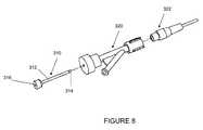
- FIG. 8shows an enlarged perspective view of a sliding, liquid-tight connector used in the interventional catheter assembly of the present invention.
- FIGS. 9A and 9Bare fluoroscopic x-ray images of a coronary artery having a removal site, wherein FIG. 9A depicts the nearly totally and diffusely occluded artery before the operation of the removal system and FIG. 9B depicts a cleared artery after use of the interventional catheter assembly of the present invention.
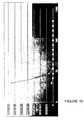
- FIG. 10shows the results of an experimental laboratory simulation in which an artificial lesion was treated using an interventional catheter of the present invention and both aspirated and non-aspirated (embolized) particulates were collected, quantified and sized.
- Interventional catheter assemblies and control systems of the present inventionare suitable for use within any body lumen or cavity that has a sufficiently open space to accept the operating head and is suspected of containing undesirable material.
- Body lumens and cavities in which such interventional catheters may be usedinclude blood vessels and vascular cavities, gastrointestinal cavities, lumens or cavities in male and female reproductive organs, other fluid cavities such as gas exchange cavities, nasal and sinus cavities, and the like.
- the lumen or cavitymay be a generally tubular-shaped structure, such as blood vessel, or another lumen structure, such as a ureter, a fallopian tube, a nasal passageway, and other tubular passageways.
- systems of the present inventionmay be used for removing undesired material from native blood vessels such as native coronary, renal, cranial, peripheral and other blood vessels, artificial or grafted vessels such as saphenous vein grafts, and the like.
- the body cavitymay also be within or in proximity to an organ, such as a kidney, gall bladder, lung, or the like, or the body cavity may form part of another system, such as a lymph node, spinal canal, etc.
- Interventional cathetersare generally used with mammalian subjects, particularly human patients.
- the undesired material that is removed using interventional catheter assemblies and control systems of the present inventionmay be disease material such as atherosclerotic plaque, calcified plaque, thrombus, gallstones, a valve or portion thereof, and the like.
- the present interventional catheter assemblyincludes an operating head and catheter system that are inserted and navigated within a patient's body while an operator controls the system externally of the operating head and catheter system. Fluidic communication between the operating head and externally positioned components of the system is generally provided by one or more sealed passageways of a catheter system. Other types of communication systems or pathways may also be provided for delivery of power, control features, and the like.
- the operating headmay be driven, or controlled, using electrical systems, radio frequency and other remote forms of control systems, mechanical systems, magnetic systems, and other systems or mediums that are in use now or may be developed in the future for remote operation of an operating head.
- the system components described beloware described as exemplary components and are not intended to limit the scope of the invention.
- Exemplary operating heads, cutter assemblies and blades, bearings, components, and subassemblies suitable for use in connection with the interventional catheters and control systems of the present inventionare disclosed and described in publications incorporated herein by reference, including U.S. Pat. No. 6,565,588B1 and PCT Patent Publication WO 01/76680, and numerous other patent publications.
- the components, subassemblies and control systems of the present inventionmay be used with interventional catheters having any type of operating head.
- Operating heads having advanceable, rotatable cutter surfaces at near their distal endsare especially suitable for use with the interventional catheter and control systems of the present invention.
- the operating headis provided at or near a distal end of the interventional catheter and is guided to and from a desired material removal site through internal passages, such as blood vessels, as is well known in the art.
- a desired material removal sitesuch as blood vessels, as is well known in the art.
- the operator headis actuated remotely by the operator to cut, grind or ablate, or otherwise separate and break down or remove undesired occlusive material.
- the occlusive materialis removed the site by means of an aspiration system or another debris removal system.
- the interventional catheter systemis generally used in conjunction with a flexible guidewire that is navigated through internal pathways, such as blood vessels, to a target material removal site.
- the guidewireis generally placed across the lesion and the operating head of the interventional catheter is advanced, on the guidewire, to the target site and then into and through the lesion.
- the operating headmay be advanced beyond the distal tip of the guidewire and into and through the obstruction, or the operating head and guidewire may be advanced in tandem.
- a guidewireis a conventionally used steering system for interventional catheters
- other methods for guiding and steering the operating headmay be used, such as radio frequency systems, stereotactic systems, magnetic systems, remote control systems, and the like.
- Interventional cathetersmay be adapted for use with any of these steering systems.
- FIG. 1depicts an exemplary embodiment of an interventional catheter assembly and control system of the present invention.
- an operating head 400is provided at or near the distal end of a catheter system 300 for insertion into a body and navigation to a target material removal site.
- the catheter system 300is operably coupled to the operating head 400 at or near a distal end and to a control pod 200 at or near a proximal end.
- a drive shaftmay also be operably coupled to the operating head at or near a distal end and operably coupled to a drive system housed within control pod 200 .
- the drive shaftmay be provided in association with one or more sealed conduits and/or layers providing withdrawal of liquids and debris from the target site or delivery of liquids to the target site, as is known in the art.
- Control pod 200houses operational and/or control components, such as a drive system, a system for translating torque from a motor drive to the drive shaft when a motor drive is used, a system for actuating and/or advancing the operating head, a guide wire clamp, one or more connectors for conduits, and/or operator controls.
- a slidable drive motor actuator 220may optionally be provided coupled to the catheter system and the operating head drive system to control operation and/or advancement of the operating head.
- Various communications pathwaysextend between the control pod 200 and a console unit 100 that houses various operating and control systems.
- a liquid conduit for collecting debris and liquid during operation of the operating headis in communication with a liquid receptacle 90 , for example.
- a liquid infusate sourcemay also be provided to provide fluid to the system, when desired.
- Console unit 100incorporates various controls and displays and houses a vacuum or aspiration motor 102 .
- Console unit 100may also provide a power source for operating the operating head and system components, or it may be in communication with an external power source.
- FIG. 2An exemplary console unit 100 is shown in more detail in FIG. 2 .
- Various software componentse.g. applications programs, may be provided within or in communication with the console unit, that cause a processor or other components to execute the numerous methods employed for controlling operation of the interventional catheter.
- the softwaremay be provided in a machine-readable medium storing executable code and/or other data to provide one or a combination of mechanisms to process user-specific data, according to one embodiment of the invention.
- various systems and componentsmay be controlled using hardware or firmware implementations.
- Data storage and processing systemsmay also be provided in console unit 100 .
- the console unitmay provide feedback of system or environmental conditions or operating parameters.
- the console unitmay output operational information concerning operating conditions and feedback from the material removal site to the operator.
- the console unitprovides continuously updated output to an operator of operating parameters such as cutter head rotation rate, which may include the actual run speed as well as the desired speed; advance rate; aspiration rate and/or volume; infusion rate and/or volume; length of the body or matter to be removed that is traversed; and the like.
- a fluid flow sensorsuch as a Doppler device, may be also included in the system and fluid flow at the target site may be monitored and displayed.
- console unit 100Certain automated and selectable control features may be implemented in console unit 100 . Preset routines or programs involving various operating parameters may be preselected, stored and selectable by an operator, for example. Thus, according to one embodiment, a material removal system of the present invention implements control features based on an operator's input of specified parameters.
- Specified parametersmay include, for example: lesion length, lesion type and character, such as calcified, fibrotic, lipid/fatty, and the like; and/or historical factors, such as restenosis; rate of blood flow; volume of blood flow; percentage of restriction; lumen type and/or location; lumen diameter; desired rotation rate and/or rotation profile for the cutter assembly; desired advance rate and/or advance profile for the cutter assembly; desired aspiration rate and/or profile; desired infusion rate and/or profile; and the like.
- an automated cutter assembly control unitmay calculate and implement automated operating conditions, such as: cutter assembly rotation rate and profile; cutter assembly advance rate and profile; aspiration rate and profile; infusion rate and profile; cutter assembly size and type; and the like.
- Various system operating parametersmay also be recorded and stored during interventions to preserve a record of the operational parameters.
- Aspiration pump 102may be provided in association with console unit 100 and, in this embodiment, console unit 100 is preferably provided as a reusable system component. High efficiency aspiration is important in the interventional catheter systems of the present invention. Aspiration pump 102 is preferably capable of providing constant, high levels of aspiration of liquids and/or liquid/debris mixtures, at rates of at least 15 ml/l through small catheter systems when the aspiration site is remote. In exemplary interventional catheter systems of the present invention, for example, the aspiration site may be more than a meter away from the control pod through an aspirate removal passageway having a diameter of less than 0.10 inch and more often between about 0.050 to 0.070 inch, and more typically about 0.065 to 0.066 inch.
- the distance that aspirate travels between the control pod and the console unitmay be from about 0.4 to several meters, through an aspirate conduit that is between about 0.125 to 0.94 inch in diameter.
- the blood and debris being aspiratedare relatively viscous fluids. Achieving a relatively constant and high level of aspiration under these conditions is essential.
- aspiration pump 102comprises a multi-lobed roller pump. At least three rollers, or lobes, are preferably incorporated in the roller pump.
- the rotation rates of multiple rollers or of a multi-lobed rotating structuremay be variable or selectable to control the aspiration rate and volume.
- Roller pumpspermit fluid to flow in conduit through the rollers of the pump at atmospheric pressure, and thus reduce or prevent the formation of bubbles and foam in the liquid being evacuated. Because the aspirate is at atmospheric pressure when it exits the roller pump, a simplified, atmospheric pressure collection vessel may be used rather than an evacuated collection vessel. A simple bag or another collection vessel, such as those used for collection of blood, may be used.
- Collection bag 90may be provided having a sealed conduit that is mounted in the roller pump and connected to an aspirate withdrawal site at the control pod during operation.
- the aspirate collection bag and sealed conduitmay be provided as part of the sterile disposable interventional catheter system and simply mounted on the aspiration pump prior to operation.
- the aspiration pumpmay comprise multiple vacuum pumps aligned in series to provide a consistent and high level of aspiration. In this manner, each pump incrementally increases pressure when it is operated in conjunction with other pumps in the series.
- the aspiration systemmay comprise multiple series of pumps connected in parallel. This system may also provide a consistent, high level of aspiration.
- Console unit 100may house a power source or provide communication to an external power source.
- an electrical device portis provided for providing electrical power to the control pod.
- An electrical conduitmay be provided mounted to electrical components in the control pod and connected to the console unit prior to operation.
- Console unit 100also has a power on/off switch that controls power to the device port.
- console unit 100may include control status indicators to show the status of various system components and/or controls.
- one or more operating head status indicatorsmay show the real-time status of the operating head.
- an operating head status indicator 104shows whether the operating head is at a minimum or maximum diameter during any operation.
- Console unit 100also has a speed gauge 106 to display that actual rotational speed of a rotating operating head during operation.
- An analog gaugemay be provided, as well as a digital gauge that shows the numerical value of rpm. The rotational speed of the operating head changes in real time to reflect the actual operating head speed as it is advanced through an obstruction.
- Console unit 100may also have control switches for activating and shutting down the aspirate withdrawal pump and system, and for activating and shutting down an infusate system. These control features are generally provided as simple switches, though selectable levels of aspiration and/or infusate may be provided. Console unit 100 may also be provided with a timing mechanism that determines, and displays, the elapsed time of operation of the operating head and/or the aspiration system. The volume of aspirate withdrawn may also be displayed.
- Console unit 100may also be provided with one or more selectable torque features.
- the selectable torque featurespermit an operator to determine the torque, or power, delivered to the operating head separately from the rotational speed and thus provides an additional level of operator control and safety.
- operation of the cutter assembly at a high torque settingmay provide overly aggressive removal of undesired material and damage healthy tissue.
- Some lesions that are composed of very hard materialmay require operation at a high torque setting, and some cutter assemblies do not damage healthy tissue even when operated at a high torque setting. It is therefore highly desirable and increases the versatility of the interventional catheter system to provide selectable torque levels for operating the operating head.
- the selectable torque control featuresmay be provided at the console unit, as shown, or they may be provided at the control pod.
- Selectable torque control featuresmay be provided by limiting the current provided to the operating head drive system.
- a maximum torque or power control setting 110allows a preselected current level, such as 1.1-1.5 amps, to be provided to the operating head drive system.
- a medium torque or power control setting 112may provide a preselected current level of from 0.7-1.3 amps to the drive motor system.
- a minimum torque or power setting 114may provide a preselected current level of less than 1 amp to the drive system.
- an additional override control featuremay be provided.
- control circuitryis provided so that when the current level required to maintain a desired rotational speed at the operating head exceeds a predetermined value, power to the operating head is inactivated and the operating head stalls. If additional power is required to remove obstructive material, the torque setting may be changed and the operating head activated and advanced into the lesion at the higher torque setting. Different preselected torque override values may be applied to each of the selectable torque settings and, if the system is programmable, may be changed by an operator prior to use.
- a torque or power gaugemay be provided as an analog or digital gauge on the console unit or control pod to show the actual torque delivered to the operating head as current drawn by the motor drive system
- the selectable torque control featuregreatly enhances the versatility and safety of the interventional catheter assembly.
- console unit 100including aspiration pump 102 , is provided as a separate, re-usable unit.
- the console unitmay therefore be purchased as standard equipment in operating rooms, for example, and the interventional catheter assembly comprising the control pod, the catheter system and operating head may be provided as sterile, single use systems.
- the console unitisn't contaminated by contact with blood or aspirate during operation, the power and control systems are durable and long-lasting, and so the console may be reused for many interventions.
- the console unitmay be provided in a housing designed to sit on a platform during operation, or the housing may be designed for mounting on a structure, such as an iv pole or another structure during operation.
- An aspirate collection vesselmay be mounted to the console during operation, or to an associated structure.
- an infusate sourcemay be mounted to the console or to an associated structure.
- a tracking pod and motor activation buttonmay also be provided as a reusable unit.
- Control pod 200is illustrated in more detail in FIG. 3A .
- Control pod 200is optionally electrically connectable to a power source, such as an electrical power source at or in communication with console unit 100 .
- Control pod 200is also in fluid communication with aspirate collection vessel via a fluid conduit, and the drive shaft, aspiration conduit and catheter system all traverse and/or exit from control pod 200 , for example, at a distal end of the pod.
- Control pod 200is constructed from a durable, sterilizable material, such as hard plastic, and may be provided in any convenient ergonomic design and constructed for placement in proximity to and/or in contact with the external body.
- the control podmay include an integrated handle or support 202 for convenience in holding and supporting the control pod during operation.
- the control podis preferably compact and may have a generally triangular configuration, as illustrated in FIG. 3A .
- control podas shown, is intended to be used within the sterile field during operation and is provided as part of the interventional catheter assembly. It will be noted, however, that some of the control and operational features of the control pod may be provided in the console unit and, likewise, some of the control and operational features of the console unit may be provided in the control pod.
- control pod 200houses a drive motor providing torque and rotation to the drive shaft and operating head.
- the drive motormay be of many types, such as electrical, pneumatic, or the like. Electrical, direct current variable speed drive motors are preferred for use in interventional catheter assemblies of the present invention because they reliably provide high power and high torque, yet numerous control systems can be implemented.
- Preferred drive motorsdeliver a constant voltage source for any given rotational output. If, under load conditions, the voltage employed to produce a given rotational output isn't sufficient, the motor system adjusts current delivered to the system to achieve the desired rotational output. The voltage delivered to the drive system is thus regulated according to the desired rotational output. In preferred embodiments employing selectable torque features, the current delivered to the drive system is regulated, and limited, by the torque selection.
- Preferred motor systemsemploy cascaded variable regulator voltage sources. The motor system may provide bidirectional output.
- the rotational output of the drive motoris preferably adjustable by the operator to control rotation of the operating head.
- Rotational speed of the drive motor, drive shaft and operating headmay be adjusted at control pod 200 at speed up and down controls 206 and 208 .
- the drive shaft and operating headare rotated at high speeds. For example, rotational speeds of from several hundred to 100,000 or 200,000 rpm may be required.
- a direction of rotation selectionmay be provided at the control pod.
- an operating head selectionmay be provided at the control pod.
- the operating headcomprises a cutter assembly that is adjustable between a smaller diameter and a larger diameter condition.
- a selection switch for tip sizemay be provided at the control pod. Tip size may be controlled by changing the direction of motor drive rotational output.
- a torque transfer sliding tube system 620may be provided for transferring torque to the drive shaft.
- the torque transfer systemboth provides torque to the drive shaft and permits smooth axial translation of the drive shaft, even at high rotational speeds.
- the sliding tube torque transfer systemalso allows the catheter system to advance over a guidewire without the drive shaft disengaging from the motor drive assembly and while a guide wire locking device maintains the guide wire position.
- Experimental workhas also demonstrated that the sliding tube torque transfer system of the present invention may provide an operator greater and more realistic tactile feel for safe and effective removal of undesired material during operation of the operating head as the lesion when a sliding tube torque transfer system is used in the interventional catheter assembly.
- Sliding tube torque transfer system 620comprises a rigid inner tube or cylinder 622 and a rigid outer tube or cylinder 624 that is axially slidable over at least a portion of the inner tube.
- Each of the tubesis provided with at least two matching slots 632 , 634 generally arranged in a radially symmetrical arrangement, with a ball bearing 628 being slidably retained between each set of slots.
- the inner and outer tubesare sized so that when a ball bearing is placed between each of the matching slots, the tubes are both axially slidable and rotatable with respect to one another.
- Slots 626preferably extend for most of the length of inner tube 622 , so that the inner and outer tubes are slidable with respect to one another along most of the length of inner tube 622 .
- the slot of the outer tubeusually extends through the body of the tube and does not include a bottom surface.
- a proximal end of the outer tubemay be operably coupled to a pinion shaft 630 of the drive system.
- the pinion shaft 630transfers torque to the outer tube and retains the ball bearings.
- the pinion shaft 630includes at least one gear 632 to operatively couple to a drive system gear. Rotational torque is transferred from the pinion shaft, to the outer tube and, through the ball bearings being positioned in the aligned channels, to the inner tube and then to a drive shaft.
- the catheter systemmay be mounted to the inner tube, such as through a main shaft 634 , which allows smooth translation of the catheter even during high rotational operations.
- Control pod 200also includes a system for preventing gases, such as air, from being drawn into structural elements that move relative to one another and into the catheter system. Preventing air leakage into the system and preventing any resulting loss of pressure in a high vacuum zone is especially important in catheter systems employing high aspiration rates and requiring relatively high vacuum levels to effectively aspirate fluids and debris from the material removal site.
- a liquid sealis established in proximity to the rotating drive shaft. This system is illustrated in FIGS. 5 and 6 A- 6 B.
- FIG. 5shows a schematic diagram of the drive system in communication with a liquid seal system of the present invention.
- Control pod 200generally houses a drive system 8 that rotates a proximal end of drive shaft 10 .
- the drive shaft 10then passes through sealing assembly 4 including a high vacuum section and is operably coupled to drive shaft 10 .
- a catheter system 6surrounds the drive shaft and extends distally to the operating head, enclosing the drive shaft and providing aspirate and/or infusion lumens.
- the sealing assemblyutilizes a drive shaft liner and takes advantage of pressure differentials within the control pod to produce a liquid seal that prevents ingress of air into the catheter system.
- FIG. 6Ashows one embodiment of sealing assembly 20 having a sealing member 22 and a liner 24 wrapped around a drive shaft 26 .
- the sealing memberincludes a housing 28 enclosing one or more sealing sites.
- the housingis a rigid member that encloses at least a portion of the drive shaft in a manner that permits free rotation and axial translation of the drive shaft.
- the housingincludes a longitudinal bore 30 through which the drive shaft is positioned.
- the boreincludes one or more axially aligned sites that form the one or more sealing/junction sites.
- At least one layer of the catheter system enclosing the drive shaftpasses into the sealing assembly at an aperture 32 .
- the proximal end of the catheter systemterminates in the sealing assembly in an aspiration zone 38 .
- the drive shaftcontinues through the sealing assembly and passes through an exit aperture, such as overflow port 56 .
- Liquidis provided to the sealing assembly at a region of substantially atmospheric pressure. This area is susceptible to leaking air to the neighboring low pressure aspiration zone.
- the liquid sealprevents air from traveling along a significant length of the drive shaft towards the material removal site.
- An infusion port 40supplies reservoir 42 for retaining liquid during operation of the interventional catheter.
- FIG. 6BAn, enlarged view of a portion of a liquid seal site 36 is shown in FIG. 6B .
- a tubular liner 24is spaced apart from and surrounds at least a portion of the longitudinal length of the drive shaft.
- the lineris generally not bonded to the drive shaft so that as the operating head is rotated, the drive shaft is rotate freely, while the liner remains stationary.
- Surface tension and head lossprevent the liquid from moving very rapidly into or very far along a flood space formed within the inside diameter of the liner, even when high vacuum levels are provided in the aspiration zone. Thus, only a minimal amount of liquid travels the flood space.
- the linermay comprise any material that is formable into a thin, tough, flexible, sealed tube.
- the lineris typically highly compliant so that it follows the contour of the drive shaft without reducing the flexibility of the drive shaft.
- the lineris supported along its length by the drive shaft, and the liner material therefore need not be stiff or resistant to changes in pressure.
- the material forming the linermay also be slippery, or lubricious, when wet or when contacting another material.
- the liner materialalso possesses high thermal resistance and does not degrade as a consequence of frictional loads created by drive shaft rotation.
- the linermay comprise conventional, polymer-based tubing comprising, for example, a polyimide material and having a lubricious surface coating, such as a polytetrafluoroethylene (PTFE), such as Teflon®, on at least the inner surface of the liner.
- a polyimide materialsuch as polyimide material
- a lubricious surface coatingsuch as a polytetrafluoroethylene (PTFE), such as Teflon®, on at least the inner surface of the liner.
- PTFEpolytetrafluoroethylene
- the dimensions of the linerdepend, inter alia, on the diameter and design of the catheter system and drive shaft, the characteristics and design of the seal assembly, and the anticipated local vacuum levels required to produce the desired level of aspiration.
- the clearance between the liner and the drive shaft at the flood spaceis typically quite small, such as about 0.002 to 0.003 inch.
- the wall thickness of the lineris typically very small, such as from about 0.001 to 0.0015 inch.
- the linerextends a distance along the axial length of the drive shaft sufficient to prevent air leakage along the length of the liner. In an exemplary system, the liner may extend for about 1 to 30 inches in length, more typically from about 6 to 25 inches in length.
- a longer lineris often desirable to minimize, due to head loss, the amount of liquid traveling the flood space and exiting the distal end of the flood space to dilute aspiration.
- the linermay consume some of the available lumen space for aspiration. Where high aspiration rates are desired, relatively shorter liner sections may be provided.
- liquidcontinues to flow into the sealing assembly from the infusion port.
- liquidflows from an external liquid source through tubing connected to the infusion port.
- liquiddrips from a conventional fluid bag that is placed a distance above the sealing assembly and feeds the sealing assembly by gravity flow.
- Saline and waterare common liquids that are suitable for use in the sealing assembly and are conveniently provided in a sterile form.
- the liquidmay comprise blood and/or plasma that is withdrawn from the patient.
- blood and/or plasma that is aspirated from the patient through the interventional cathetermay be treated by filtration, mixed with agents such as anticlotting or treatment agents and then introduced into the infusion port to provide liquid for the sealing assembly.
- Control pod 200may additionally house an extendable, telescoping guidewire support, which reduces the size requirements of the control pod and provides guidewire support over a variable length.
- FIG. 7illustrates one embodiment of a guidewire support 250 comprising a folding assembly having aligned holes for passage of a guidewire.
- Each panel 252 of guidewire support 250has substantially the same dimensions, has a guidewire passageway 254 in a location corresponding to guidewire passageways in the other panels, and is foldable along each of its sidewalls with respect to adjacent panels.
- the guidewire passagewaysare preferably sized to allow passage of guidewires having a range of diameters.
- the guidewire supportmay be mounted at a proximal end to the motor drive or another structure within the control pod and may be mounted at a distal end to the guidewire brake or another structure within the control pod.
- the guidewire supportis adjustable between a shorter, substantially folded condition and a longer, substantially extended condition as the structures between which the support is mounted move relative to one another.
- the guidewire supportis adjustable between a shorter, substantially folded condition in which the axial length of the guidewire support is about one inch or less and a longer, extended condition in which the axial length of the guidewire support is about 6 inches or more.
- the guidewire brake positionis monitored, for example using an electrical or optical device that senses whether the guidewire brake is in a clamped or a release position.
- a control system interruptprevents the motor drive and aspiration systems from being actuated and, consequently, the operating head is not operable.
- the control systempermits rotation and advancement of the operating head when the guidewire brake is in a clamped condition. This control system interrupt ensures that the guidewire brake is appropriately clamped before the operating head is actuated.
- a selectable interrupt override control 212may be provided to permit an operator to override the interrupt control and permit translation and/or rotation of the operating head while the guidewire is simultaneously moved.
- the selectable interrupt override controlmay be positioned in proximity to the guidewire brake on the control pod or remotely on the console unit, for example.
- a slidable drive motor actuator 220is slidable over catheter system 222 and is in operable communication with the operating head and drive shaft drive system.
- the operable communicationmay be provided by means of an electrical conduit communicating between actuator 220 and the drive system, or communication may be provided by wireless mechanisms.
- slidable drive motor actuator 220incorporates a switch 224 that, when actuated, such as by depressing a button, activates the drive system and/or an aspiration system. When the switch is released, the drive system and/or aspiration system are inactivated.
- Slidable actuator 220also incorporates a clamp mechanism that securely grips the catheter system over which it is slidable when actuated.
- the clamp mechanismactuated and released by the same switch 224 that activates the drive and/or aspiration systems.
- the sliding actuatormay be freely translated along and repositioned on the catheter system when the motor and/or aspiration systems are inactivated.
- the switchis actuated, such as by an operator gripping the motor actuator between a thumb and finger and depressing switch 224 , the drive system and/or aspiration system is actuated and the catheter system, drive shaft and operating head may be translated, e.g. advanced into or withdrawn from a target operating site and operated to remove undesired material.
- a delaymay be incorporated between the time the drive system and aspiration system are activated, such that the aspiration system may be actuated immediately upon actuation of the switch, while the drive system may be actuated after a predetermined or selectable delay period.
- the activation delay periodallows the aspiration system to be operating at full aspiration capacity prior to actuation of the drive system and operation of the operating head.
- a delay periodmay also be incorporated when the operating head is inactivated, such that the drive system is inactivated immediately upon release of the switch, while the aspiration system may be inactivated after a predetermined or selectable delay period. This inactivation delay period allows the aspiration system to continue operating for a short period after the operating head is inactivated to ensure that all debris is removed from the operating site.
- Catheter system 300exiting the proximal end of control pod 200 , is axially translatable with respect to the control pod 200 as the operating head and catheter system are guided to a target material removal site. Flexibility of the catheter system is important, and the catheter system must also have sufficient integrity to prevent collapse of the catheter system during aspiration. All or particular sections of the catheter system may additionally be constructed to provide non-kinking properties. Because the catheter system carries the drive shaft and aspiration and/or infusion lumens, it is essential that the catheter system remain flexible and non-kinking during navigation to the target material removal site, and during operation of the operating head.
- a non-kinking, noncollapsing catheteris provided using a multi-layer construction in which a coil constructed from a rigid material, such as a metal, is interposed between and is concentric with an inner flexible tube layer and an outer flexible tube layer.
- the coilis preferably only bonded to either the inner or outer flexible layers at one or both ends of the coil and the remaining portion of the coil is free, so that as the multi-layer catheter is flexed, all of the layers are capable of flexing independently of one another.
- the inner and outer tube layersmay comprise any flexible tubular material, such as polyimide, and may have a lubricious coating, such as a PFTE coating on surfaces that contact the coil.
- a thermally shrinkable coating that is etchedis provided. The coating is applied by shrinking a tube to 25 percent or less of the tube's original diameter prior to heating.
- the multiple catheter system layersare preferably sized to provide firm contact between adjacent layers and to allow sufficient internal space to provide the required internal lumen(s).
- the outer flexible layermay be thicker than the inner flexible layer.
- a non-kinking catheter constructionmay be provided along the entire length of the catheter system, or along a portion of the length.
- the portion of the catheter system that exits the control pod when the operating head is positioned near a target sitemay be particularly prone to kinking, and providing a multi-layer catheter construction of this type at the proximal end of the catheter system is especially suitable.
- the catheter systemis introduced to a body through an entry system placed to access an internal passageway, such as the femoral artery. Ports are provided in the entry system for passage of the catheter system.
- the catheter systemmay be introduced through the port and then translated through the port and guided to the target material removal site. Clamps are generally provided for sealing against the catheter system after placement at the target site. Sealing against fluid leakage from the port is often problematic, however, as the catheter system is guided to the target site.
- the interventional catheter assembly of the present inventionmay incorporate a fluid-tight slip seal adapter in its proximal region that slides over the catheter system to seal a connector of the entry system through which the catheter system is guided into the body from fluid leakage.
- Teflon®that permits the enclosed catheter to move in a lateral and/or rotational direction and yet maintains the close contact with the catheter.
- shrinkable materialWhen the shrinkable material is processed, it tightly grips the tube of the adaptor insertion end, while the seal section extending beyond the adaptor insertion end is not supported by the adaptor and shrinks to a diameter that is less than that of the adaptor.
- the inner diameter of the seal sectiongenerally matches the outer diameter of the catheter system and, as a consequence of the lubricious properties of the material, is slidable over the catheter system.
- the seal sectionsnugly contacts the catheter system and prevents leakage of fluids such as blood, through the port of the entry system. This provides a liquid-tight connection in the insertion system without applying a clamping pressure that deforms or damages the catheter system.
- Example 1shows images of blood vessels before and after a material removal operation
- Example 2describes laboratory tests demonstrating the aspiration efficiency of an interventional catheter assembly of the present invention.
- FIGS. 9A and 9Bare fluoroscopic x-ray images showing the results of using an interventional catheter assembly of the present invention.
- FIG. 9Ashows a nearly totally and diffusely occluded artery having a coronary bypass graft. The patient was injected with an ionic contrast agent to visualize blood flow and blockages.
- the interventional catheter system of the present inventionis used to clear the obstruction, often followed by insertion of a stent.
- a guiding catheteris inserted into the patient and a guide wire was directed to the target site in the artery.
- the cutteris rotated at 35,000 to 40,000 rpm's while aspirating at the target site.
- the cutteris advanced with little applied force into the lesion for 3 seconds at a rate of at 1 mm per second.
- the advancing movementis paused to allow cut particles to be aspirated into the cutter assembly and then the advancing movement is repeated.
- Contrast agentis applied to the area to visualize the intermediate results of the cutting and to decide on whether to use an expanded diameter of the adjustable cutter on further passes into the target site.
- a stentis inserted at the target site.
- FIG. 9Bshows the same artery and coronary bypass graft of FIG. 9A , following removal of obstructions using the interventional catheter assembly described herein, followed by stenting.
- FIG. 10shows experimental results using the interventional catheter assembly of the present invention in a laboratory model of obstructive heart disease.
- a 2 cm long lesionwas simulated in a blood vessel-like structure and a liquid having a viscosity equivalent to blood was circulated.
- Aspirated and embolized particulate materialswere collected as an interventional catheter system was advanced and rotated through the lesion.
- the size of the collected particulateswas measured and the collected particulates were quantified.
- particles of all sizeswere effectively aspirated.
- FIG. 10shows experimental results using the interventional catheter assembly of the present invention in a laboratory model of obstructive heart disease.
- interventional catheter assembly of the present inventionconstructed as described herein produced an aspiration efficiency of 97%.
Landscapes
- Health & Medical Sciences (AREA)
- Life Sciences & Earth Sciences (AREA)
- Engineering & Computer Science (AREA)
- Heart & Thoracic Surgery (AREA)
- Surgery (AREA)
- Biomedical Technology (AREA)
- Animal Behavior & Ethology (AREA)
- General Health & Medical Sciences (AREA)
- Public Health (AREA)
- Veterinary Medicine (AREA)
- Medical Informatics (AREA)
- Molecular Biology (AREA)
- Vascular Medicine (AREA)
- Biophysics (AREA)
- Pathology (AREA)
- Physics & Mathematics (AREA)
- Nuclear Medicine, Radiotherapy & Molecular Imaging (AREA)
- Immunology (AREA)
- Anesthesiology (AREA)
- Pulmonology (AREA)
- Hematology (AREA)
- Endocrinology (AREA)
- Human Computer Interaction (AREA)
- Mechanical Engineering (AREA)
- Surgical Instruments (AREA)
- Radiology & Medical Imaging (AREA)
- Media Introduction/Drainage Providing Device (AREA)
- Infusion, Injection, And Reservoir Apparatuses (AREA)
Abstract
Description
Claims (20)
Priority Applications (4)
| Application Number | Priority Date | Filing Date | Title |
|---|---|---|---|
| US10/798,621US7713231B2 (en) | 2003-03-10 | 2004-03-10 | Interventional catheter assemblies and control systems |
| US12/769,587US8323240B2 (en) | 2003-03-10 | 2010-04-28 | Interventional catheter assemblies and control systems |
| US13/691,634US8951224B2 (en) | 2003-03-10 | 2012-11-30 | Interventional catheter assemblies, control systems and operating methods |
| US14/618,659US10149698B2 (en) | 2003-03-10 | 2015-02-10 | Interventional catheter assemblies, control systems and operating methods |
Applications Claiming Priority (2)
| Application Number | Priority Date | Filing Date | Title |
|---|---|---|---|
| US45384603P | 2003-03-10 | 2003-03-10 | |
| US10/798,621US7713231B2 (en) | 2003-03-10 | 2004-03-10 | Interventional catheter assemblies and control systems |
Related Child Applications (1)
| Application Number | Title | Priority Date | Filing Date |
|---|---|---|---|
| US12/769,587DivisionUS8323240B2 (en) | 2003-03-10 | 2010-04-28 | Interventional catheter assemblies and control systems |
Publications (2)
| Publication Number | Publication Date |
|---|---|
| US20040220519A1 US20040220519A1 (en) | 2004-11-04 |
| US7713231B2true US7713231B2 (en) | 2010-05-11 |
Family
ID=36703959
Family Applications (9)
| Application Number | Title | Priority Date | Filing Date |
|---|---|---|---|
| US10/442,888Expired - Fee RelatedUS7344546B2 (en) | 2000-04-05 | 2003-05-20 | Intralumenal material removal using a cutting device for differential cutting |
| US10/760,759Active2027-04-17US7674272B2 (en) | 2003-03-10 | 2004-01-20 | Bearing system to support a rotatable operating head in an intracorporeal device |
| US10/798,622Expired - Fee RelatedUS7485127B2 (en) | 2003-03-10 | 2004-03-10 | Tubular torque transmitting system for medical device |
| US10/798,603AbandonedUS20040236312A1 (en) | 2003-03-10 | 2004-03-10 | Seal for a connector of a movable catheter system |
| US10/798,621Active2026-12-20US7713231B2 (en) | 2003-03-10 | 2004-03-10 | Interventional catheter assemblies and control systems |
| US12/050,833AbandonedUS20080228208A1 (en) | 2003-03-10 | 2008-03-18 | Intralumenal material removal using a cutting device for differential cutting |
| US12/769,587Expired - Fee RelatedUS8323240B2 (en) | 2003-03-10 | 2010-04-28 | Interventional catheter assemblies and control systems |
| US13/691,634Expired - LifetimeUS8951224B2 (en) | 2003-03-10 | 2012-11-30 | Interventional catheter assemblies, control systems and operating methods |
| US14/618,659Expired - LifetimeUS10149698B2 (en) | 2003-03-10 | 2015-02-10 | Interventional catheter assemblies, control systems and operating methods |
Family Applications Before (4)
| Application Number | Title | Priority Date | Filing Date |
|---|---|---|---|
| US10/442,888Expired - Fee RelatedUS7344546B2 (en) | 2000-04-05 | 2003-05-20 | Intralumenal material removal using a cutting device for differential cutting |
| US10/760,759Active2027-04-17US7674272B2 (en) | 2003-03-10 | 2004-01-20 | Bearing system to support a rotatable operating head in an intracorporeal device |
| US10/798,622Expired - Fee RelatedUS7485127B2 (en) | 2003-03-10 | 2004-03-10 | Tubular torque transmitting system for medical device |
| US10/798,603AbandonedUS20040236312A1 (en) | 2003-03-10 | 2004-03-10 | Seal for a connector of a movable catheter system |
Family Applications After (4)
| Application Number | Title | Priority Date | Filing Date |
|---|---|---|---|
| US12/050,833AbandonedUS20080228208A1 (en) | 2003-03-10 | 2008-03-18 | Intralumenal material removal using a cutting device for differential cutting |
| US12/769,587Expired - Fee RelatedUS8323240B2 (en) | 2003-03-10 | 2010-04-28 | Interventional catheter assemblies and control systems |
| US13/691,634Expired - LifetimeUS8951224B2 (en) | 2003-03-10 | 2012-11-30 | Interventional catheter assemblies, control systems and operating methods |
| US14/618,659Expired - LifetimeUS10149698B2 (en) | 2003-03-10 | 2015-02-10 | Interventional catheter assemblies, control systems and operating methods |
Country Status (3)
| Country | Link |
|---|---|
| US (9) | US7344546B2 (en) |
| CN (1) | CN100418484C (en) |
| AT (1) | ATE405226T1 (en) |
Cited By (51)
| Publication number | Priority date | Publication date | Assignee | Title |
|---|---|---|---|---|
| US20110040238A1 (en)* | 2009-08-12 | 2011-02-17 | Pathway Medical Technologies, Inc. | Interventional catheter assemblies incorporating guide wire brake and management systems |
| US20110112562A1 (en)* | 2003-03-10 | 2011-05-12 | Pathway Medical Technologies, Inc. | Interventional catheter assemblies and control systems |
| US20120130415A1 (en)* | 2010-11-15 | 2012-05-24 | Vascular Insights Llc | Vascular treatment device |
| US8961551B2 (en) | 2006-12-22 | 2015-02-24 | The Spectranetics Corporation | Retractable separating systems and methods |
| US9005166B2 (en) | 2003-04-08 | 2015-04-14 | Bayer Medical Care Inc. | Fluid delivery systems, devices and methods for delivery of hazardous fluids |
| US9028520B2 (en) | 2006-12-22 | 2015-05-12 | The Spectranetics Corporation | Tissue separating systems and methods |
| US9108027B2 (en)* | 2013-02-26 | 2015-08-18 | Boston Scientific Scimed, Inc. | Interventional catheter housing assemblies incorporating guide wire brakes and management systems |
| US9108047B2 (en) | 2010-06-04 | 2015-08-18 | Bayer Medical Care Inc. | System and method for planning and monitoring multi-dose radiopharmaceutical usage on radiopharmaceutical injectors |
| US9283040B2 (en) | 2013-03-13 | 2016-03-15 | The Spectranetics Corporation | Device and method of ablative cutting with helical tip |
| US9291663B2 (en) | 2013-03-13 | 2016-03-22 | The Spectranetics Corporation | Alarm for lead insulation abnormality |
| US9413896B2 (en) | 2012-09-14 | 2016-08-09 | The Spectranetics Corporation | Tissue slitting methods and systems |
| USD765243S1 (en) | 2015-02-20 | 2016-08-30 | The Spectranetics Corporation | Medical device handle |
| USD766433S1 (en) | 2013-11-04 | 2016-09-13 | Cardiovascular Systems, Inc. | Eccentric crown |
| US9456872B2 (en) | 2013-03-13 | 2016-10-04 | The Spectranetics Corporation | Laser ablation catheter |
| US9468457B2 (en) | 2013-09-30 | 2016-10-18 | Cardiovascular Systems, Inc. | Atherectomy device with eccentric crown |
| USD770616S1 (en) | 2015-02-20 | 2016-11-01 | The Spectranetics Corporation | Medical device handle |
| US9603618B2 (en) | 2013-03-15 | 2017-03-28 | The Spectranetics Corporation | Medical device for removing an implanted object |
| US9649437B2 (en) | 2013-03-14 | 2017-05-16 | Boston Scientific Scimed, Inc. | Interventional catheter assemblies and control components for interventional catheter assemblies |
| US9668765B2 (en) | 2013-03-15 | 2017-06-06 | The Spectranetics Corporation | Retractable blade for lead removal device |
| US9855070B2 (en) | 2014-03-12 | 2018-01-02 | Boston Scientific Limited | Infusion lubricated atherectomy catheter |
| US9883885B2 (en) | 2013-03-13 | 2018-02-06 | The Spectranetics Corporation | System and method of ablative cutting and pulsed vacuum aspiration |
| US9918705B2 (en) | 2016-07-07 | 2018-03-20 | Brian Giles | Medical devices with distal control |
| US9925366B2 (en) | 2013-03-15 | 2018-03-27 | The Spectranetics Corporation | Surgical instrument for removing an implanted object |
| US9980743B2 (en) | 2013-03-15 | 2018-05-29 | The Spectranetics Corporation | Medical device for removing an implanted object using laser cut hypotubes |
| US10052122B2 (en) | 2014-01-17 | 2018-08-21 | Cardiovascular Systems, Inc. | Spin-to-open atherectomy device with electric motor control |
| US10136913B2 (en) | 2013-03-15 | 2018-11-27 | The Spectranetics Corporation | Multiple configuration surgical cutting device |
| US10271869B2 (en) | 2014-03-01 | 2019-04-30 | Rex Medical, L.P. | Atherectomy device |
| US10307175B2 (en) | 2016-03-26 | 2019-06-04 | Rex Medical, L.P | Atherectomy device |
| US10383691B2 (en) | 2013-03-13 | 2019-08-20 | The Spectranetics Corporation | Last catheter with helical internal lumen |
| US10391274B2 (en) | 2016-07-07 | 2019-08-27 | Brian Giles | Medical device with distal torque control |
| US10405924B2 (en) | 2014-05-30 | 2019-09-10 | The Spectranetics Corporation | System and method of ablative cutting and vacuum aspiration through primary orifice and auxiliary side port |
| US10405878B2 (en) | 2014-07-25 | 2019-09-10 | Boston Scientific Scimed, Inc. | Rotatable medical device |
| US10405879B2 (en) | 2014-12-04 | 2019-09-10 | Boston Scientific Scimed, Inc. | Rotatable medical device |
| US10433868B2 (en) | 2014-12-27 | 2019-10-08 | Rex Medical, L.P. | Artherectomy device |
| US10448999B2 (en) | 2013-03-15 | 2019-10-22 | The Spectranetics Corporation | Surgical instrument for removing an implanted object |
| EP3407809A4 (en)* | 2016-01-27 | 2019-10-23 | Fusion Medical, Inc. | CLAMP REMOVAL DEVICE FOR BLOOD VESSELS |
| US10463388B2 (en) | 2006-09-13 | 2019-11-05 | Merit Medical Systems, Inc. | Wire and device for vascular treatment |
| US10463389B2 (en) | 2014-12-27 | 2019-11-05 | Rex Medical, L.P. | Atherectomy device |
| US10722238B2 (en) | 2012-05-09 | 2020-07-28 | Fusion Medical, Inc. | Clot removal device for deep vein thrombosis |
| US10835279B2 (en) | 2013-03-14 | 2020-11-17 | Spectranetics Llc | Distal end supported tissue slitting apparatus |
| US10842532B2 (en) | 2013-03-15 | 2020-11-24 | Spectranetics Llc | Medical device for removing an implanted object |
| US11253292B2 (en) | 2015-09-13 | 2022-02-22 | Rex Medical, L.P. | Atherectomy device |
| US11337724B2 (en) | 2019-03-15 | 2022-05-24 | Terumo Kabushiki Kaisha | Method and system for controlling rotational speed of an agitator or catheter |
| US11382652B2 (en) | 2018-05-08 | 2022-07-12 | Boston Scientific Scimed, Inc. | Device guidewire management accessory |
| US11627982B2 (en)* | 2019-03-15 | 2023-04-18 | Terumo Kabushiki Kaisha | Method and system for controlling rotational speed of an agitator or catheter |
| US11679194B2 (en) | 2021-04-27 | 2023-06-20 | Contego Medical, Inc. | Thrombus aspiration system and methods for controlling blood loss |
| US11696793B2 (en) | 2021-03-19 | 2023-07-11 | Crossfire Medical Inc | Vascular ablation |
| US11911581B1 (en) | 2022-11-04 | 2024-02-27 | Controlled Delivery Systems, Inc. | Catheters and related methods for the aspiration controlled delivery of closure agents |
| US12053203B2 (en) | 2014-03-03 | 2024-08-06 | Spectranetics, Llc | Multiple configuration surgical cutting device |
| US12137928B2 (en) | 2019-03-15 | 2024-11-12 | Terumo Kabushiki Kaisha | Method and system for controlling rotational speed of an agitator or catheter |
| US12285174B2 (en) | 2022-11-04 | 2025-04-29 | Solvein, Inc. | Two balloon catheters for aspiration and controlled delivery of closure agents |
Families Citing this family (253)
| Publication number | Priority date | Publication date | Assignee | Title |
|---|---|---|---|---|
| US6482217B1 (en)* | 1998-04-10 | 2002-11-19 | Endicor Medical, Inc. | Neuro thrombectomy catheter |
| US8328829B2 (en) | 1999-08-19 | 2012-12-11 | Covidien Lp | High capacity debulking catheter with razor edge cutting window |
| US7713279B2 (en) | 2000-12-20 | 2010-05-11 | Fox Hollow Technologies, Inc. | Method and devices for cutting tissue |
| US7708749B2 (en) | 2000-12-20 | 2010-05-04 | Fox Hollow Technologies, Inc. | Debulking catheters and methods |
| US6299622B1 (en) | 1999-08-19 | 2001-10-09 | Fox Hollow Technologies, Inc. | Atherectomy catheter with aligned imager |
| US10092313B2 (en)* | 2000-04-05 | 2018-10-09 | Boston Scientific Limited | Medical sealed tubular structures |
| US20040243162A1 (en)* | 2000-04-05 | 2004-12-02 | Pathway Medical Technologies, Inc. | Interventional catheter assemblies and control systems |
| US8475484B2 (en)* | 2000-04-05 | 2013-07-02 | Medrad, Inc. | Liquid seal assembly for a rotating torque tube |
| JP5190169B2 (en) | 2000-10-19 | 2013-04-24 | アプライド メディカル リソーシーズ コーポレイション | Surgical access instruments and methods |
| JP4080874B2 (en) | 2000-12-20 | 2008-04-23 | フォックス ハロウ テクノロジーズ,インコーポレイティド | Bulking catheter |
| US7047058B1 (en) | 2001-02-06 | 2006-05-16 | Medrad, Inc. | Apparatuses, systems and methods for extravasation detection |
| EP2422829B1 (en) | 2001-08-14 | 2013-03-06 | Applied Medical Resources Corporation | Surgical access sealing apparatus |
| US6958037B2 (en) | 2001-10-20 | 2005-10-25 | Applied Medical Resources Corporation | Wound retraction apparatus and method |
| EP2343032B1 (en) | 2002-06-05 | 2012-05-09 | Applied Medical Resources Corporation | Wound retractor |
| US20050020884A1 (en) | 2003-02-25 | 2005-01-27 | Hart Charles C. | Surgical access system |
| US8246640B2 (en) | 2003-04-22 | 2012-08-21 | Tyco Healthcare Group Lp | Methods and devices for cutting tissue at a vascular location |
| CA2533204A1 (en) | 2003-08-06 | 2005-02-17 | Applied Medical Resources Corporation | Surgical device with tack-free gel and method of manufacture |
| US20050251102A1 (en)* | 2003-09-26 | 2005-11-10 | Michael Hegland | Catheter connection systems and methods |
| US20060089637A1 (en) | 2004-10-14 | 2006-04-27 | Werneth Randell L | Ablation catheter |
| US8617152B2 (en) | 2004-11-15 | 2013-12-31 | Medtronic Ablation Frontiers Llc | Ablation system with feedback |
| US7468062B2 (en) | 2004-11-24 | 2008-12-23 | Ablation Frontiers, Inc. | Atrial ablation catheter adapted for treatment of septal wall arrhythmogenic foci and method of use |
| US7429261B2 (en) | 2004-11-24 | 2008-09-30 | Ablation Frontiers, Inc. | Atrial ablation catheter and method of use |
| JP5219518B2 (en) | 2004-12-09 | 2013-06-26 | ザ ファウンドリー, エルエルシー | Aortic valve repair |
| US20060142775A1 (en)* | 2004-12-29 | 2006-06-29 | Depuy Mitek, Inc. | Surgical tool with cannulated rotary tip |
| WO2006127123A2 (en) | 2005-05-20 | 2006-11-30 | Medtronic, Inc. | Locking catheter connector and method |
| US7387624B2 (en) | 2005-05-20 | 2008-06-17 | Medtronic, Inc. | Squeeze-actuated catheter connecter and method |
| EP2759276A1 (en) | 2005-06-20 | 2014-07-30 | Medtronic Ablation Frontiers LLC | Ablation catheter |
| AU2006268238A1 (en) | 2005-07-11 | 2007-01-18 | Medtronic Ablation Frontiers Llc | Low power tissue ablation system |
| US8657814B2 (en)* | 2005-08-22 | 2014-02-25 | Medtronic Ablation Frontiers Llc | User interface for tissue ablation system |
| JP4864003B2 (en)* | 2005-09-30 | 2012-01-25 | オリンパスメディカルシステムズ株式会社 | Rotating self-propelled endoscope device |
| AU2006304141B2 (en) | 2005-10-14 | 2012-07-05 | Applied Medical Resources Corporation | Gel cap for wound retractor |
| WO2007080783A1 (en)* | 2006-01-13 | 2007-07-19 | Olympus Medical Systems Corp. | Rotary self-running endoscope system, program, and method of driving rotary self-running endoscope system |
| US20070276419A1 (en) | 2006-05-26 | 2007-11-29 | Fox Hollow Technologies, Inc. | Methods and devices for rotating an active element and an energy emitter on a catheter |
| US8628549B2 (en)* | 2006-06-30 | 2014-01-14 | Atheromed, Inc. | Atherectomy devices, systems, and methods |
| US20080045986A1 (en)* | 2006-06-30 | 2008-02-21 | Atheromed, Inc. | Atherectomy devices and methods |
| US8007506B2 (en) | 2006-06-30 | 2011-08-30 | Atheromed, Inc. | Atherectomy devices and methods |
| US9314263B2 (en)* | 2006-06-30 | 2016-04-19 | Atheromed, Inc. | Atherectomy devices, systems, and methods |
| US8361094B2 (en) | 2006-06-30 | 2013-01-29 | Atheromed, Inc. | Atherectomy devices and methods |
| AU2007269274A1 (en)* | 2006-06-30 | 2008-01-10 | Atheromed, Inc. | Atherectomy devices and methods |
| US20090018566A1 (en)* | 2006-06-30 | 2009-01-15 | Artheromed, Inc. | Atherectomy devices, systems, and methods |
| US7981128B2 (en)* | 2006-06-30 | 2011-07-19 | Atheromed, Inc. | Atherectomy devices and methods |
| US20110112563A1 (en)* | 2006-06-30 | 2011-05-12 | Atheromed, Inc. | Atherectomy devices and methods |
| US9492192B2 (en)* | 2006-06-30 | 2016-11-15 | Atheromed, Inc. | Atherectomy devices, systems, and methods |
| EP2462882B1 (en) | 2006-10-04 | 2016-12-28 | Boston Scientific Limited | Interventional catheters |
| US7988674B2 (en)* | 2006-10-30 | 2011-08-02 | Medtronic, Inc. | Externally releasable body portal anchors and systems |
| US20080125849A1 (en)* | 2006-11-13 | 2008-05-29 | Janet Burpee | Delivery system catheter with rotating distal end |
| CA2676787A1 (en)* | 2007-02-05 | 2008-08-14 | Boston Scientific Limited | System with catheter system and an adaptor comprising a friction reducing sleeve, and methods of use |
| WO2008141291A1 (en) | 2007-05-11 | 2008-11-20 | Applied Medical Resources Corporation | Surgical retractor with gel pad |
| EP2146644A4 (en) | 2007-05-11 | 2012-07-18 | Applied Med Resources | Surgical retractor |
| US8641704B2 (en) | 2007-05-11 | 2014-02-04 | Medtronic Ablation Frontiers Llc | Ablation therapy system and method for treating continuous atrial fibrillation |
| US7828710B2 (en)* | 2007-06-05 | 2010-11-09 | Medical Value Partners, Llc | Apparatus comprising a drive cable for a medical device |
| US8003157B2 (en) | 2007-06-15 | 2011-08-23 | Abbott Cardiovascular Systems Inc. | System and method for coating a stent |
| US8677650B2 (en)* | 2007-06-15 | 2014-03-25 | Abbott Cardiovascular Systems Inc. | Methods and devices for drying coated stents |
| AU2008271034A1 (en)* | 2007-06-29 | 2009-01-08 | Atheromed, Inc. | Atherectomy devices, systems, and methods |
| ATE459295T1 (en)* | 2007-07-20 | 2010-03-15 | Wolf Gmbh Richard | ENDOSCOPIC INSTRUMENT |
| US20090048562A1 (en)* | 2007-08-18 | 2009-02-19 | Falk Theodore J | Ambulatory Infusion Devices And Piston Pumps For Use With Same |
| US9034007B2 (en) | 2007-09-21 | 2015-05-19 | Insera Therapeutics, Inc. | Distal embolic protection devices with a variable thickness microguidewire and methods for their use |
| US8236016B2 (en) | 2007-10-22 | 2012-08-07 | Atheromed, Inc. | Atherectomy devices and methods |
| WO2009054968A1 (en)* | 2007-10-22 | 2009-04-30 | Atheromed, Inc. | Atherectomy devices and methods |
| US8070762B2 (en)* | 2007-10-22 | 2011-12-06 | Atheromed Inc. | Atherectomy devices and methods |
| US8613721B2 (en)* | 2007-11-14 | 2013-12-24 | Medrad, Inc. | Delivery and administration of compositions using interventional catheters |
| US8784654B2 (en)* | 2007-11-14 | 2014-07-22 | Bayer Medical Care, Inc. | Methods and systems for biological sample collection and analysis |
| US20090149775A1 (en)* | 2007-12-07 | 2009-06-11 | Harry Lander | Variable-Diameter Punch Biopsy |
| US8062226B2 (en)* | 2007-12-17 | 2011-11-22 | Silicon Valley Medical Instruments, Inc. | Telescope for an imaging catheter |
| US8784440B2 (en) | 2008-02-25 | 2014-07-22 | Covidien Lp | Methods and devices for cutting tissue |
| WO2009114734A1 (en)* | 2008-03-13 | 2009-09-17 | Boston Scientific Scimed, Inc. | Methods and apparatus for inhibiting introduction of air into the vasculature during a percutaneous procedure |
| US8062316B2 (en) | 2008-04-23 | 2011-11-22 | Avinger, Inc. | Catheter system and method for boring through blocked vascular passages |
| US20100125253A1 (en)* | 2008-11-17 | 2010-05-20 | Avinger | Dual-tip Catheter System for Boring through Blocked Vascular Passages |
| US9788790B2 (en) | 2009-05-28 | 2017-10-17 | Avinger, Inc. | Optical coherence tomography for biological imaging |
| US9125562B2 (en) | 2009-07-01 | 2015-09-08 | Avinger, Inc. | Catheter-based off-axis optical coherence tomography imaging system |
| US8696695B2 (en) | 2009-04-28 | 2014-04-15 | Avinger, Inc. | Guidewire positioning catheter |
| US8192451B2 (en)* | 2008-06-05 | 2012-06-05 | Cardiovascular Systems, Inc. | Cutting and coring atherectomy device and method |
| US9186170B2 (en)* | 2008-06-05 | 2015-11-17 | Cardiovascular Systems, Inc. | Bidirectional expandable head for rotational atherectomy device |
| CA2739910C (en) | 2008-10-13 | 2017-06-06 | Applied Medical Resources Corporation | Single port access system |
| US8414604B2 (en) | 2008-10-13 | 2013-04-09 | Covidien Lp | Devices and methods for manipulating a catheter shaft |
| US8795303B2 (en)* | 2009-02-02 | 2014-08-05 | Cardiovascular Systems, Inc. | Multi-material abrading head for atherectomy devices having laterally displaced center of mass |
| CN102625673B (en) | 2009-04-29 | 2014-12-24 | 泰科保健集团有限合伙公司 | Methods and devices for cutting and abrading tissue |
| US8632557B2 (en)* | 2009-05-12 | 2014-01-21 | Cardiovascular Systems, Inc. | Rotational atherectomy device and method to improve abrading efficiency |
| WO2010132748A1 (en) | 2009-05-14 | 2010-11-18 | Fox Hollow Technologies, Inc. | Easily cleaned atherectomy catheters and methods of use |
| US8795304B2 (en)* | 2009-06-18 | 2014-08-05 | Cardiovascular Systems, Inc. | Atherectomy device, system and method having a bi-directional distal expandable ablation element |
| WO2011003006A2 (en) | 2009-07-01 | 2011-01-06 | Avinger, Inc. | Atherectomy catheter with laterally-displaceable tip |
| EP2467065B1 (en) | 2009-11-13 | 2020-01-08 | Intuitive Surgical Operations, Inc. | End effector with redundant closing mechanisms |
| KR102152042B1 (en) | 2009-11-13 | 2020-09-04 | 인튜어티브 서지컬 오퍼레이션즈 인코포레이티드 | Surgical tool with a compact wrist |
| US20110118708A1 (en) | 2009-11-13 | 2011-05-19 | Intuitive Surgical Operations, Inc. | Double universal joint |
| EP2498710B1 (en) | 2009-11-13 | 2018-05-16 | Intuitive Surgical Operations, Inc. | Motor interface for parallel drive shafts within an independently rotating member |
| WO2011068932A1 (en) | 2009-12-02 | 2011-06-09 | Fox Hollow Technologies, Inc. | Methods and devices for cutting tissue |
| WO2011072068A2 (en) | 2009-12-08 | 2011-06-16 | Avinger, Inc. | Devices and methods for predicting and preventing restenosis |
| CN102695463B (en) | 2009-12-11 | 2015-01-14 | 泰科保健集团有限合伙公司 | Material removal device having improved material capture efficiency and methods of use |
| US8632558B2 (en)* | 2010-01-20 | 2014-01-21 | Pavilion Medical Innovations, Llc | Systems and methods for removal of intravascular leads |
| DE102010007177B4 (en) | 2010-02-08 | 2017-06-22 | Siemens Healthcare Gmbh | Display method for an image of the interior of a vessel located in front of a widening device and display device corresponding thereto |
| US9050126B2 (en)* | 2010-02-26 | 2015-06-09 | Cardiovascular Systems, Inc. | Rotational atherectomy device with electric motor |
| US10952764B2 (en) | 2010-05-04 | 2021-03-23 | Samuel Shiber | Rotary catheter drive unit containing seal-sets |
| US20150094733A1 (en) | 2010-05-04 | 2015-04-02 | Samuel Shiber | Rotary catheter drive unit containing seal-sets |
| US9907567B2 (en) | 2010-05-04 | 2018-03-06 | Samuel Shiber | Mechanical — pharmaceutical system for opening obstructed bodily vessels |
| US8663259B2 (en) | 2010-05-13 | 2014-03-04 | Rex Medical L.P. | Rotational thrombectomy wire |
| US8764779B2 (en) | 2010-05-13 | 2014-07-01 | Rex Medical, L.P. | Rotational thrombectomy wire |
| US9023070B2 (en) | 2010-05-13 | 2015-05-05 | Rex Medical, L.P. | Rotational thrombectomy wire coupler |
| US9795406B2 (en) | 2010-05-13 | 2017-10-24 | Rex Medical, L.P. | Rotational thrombectomy wire |
| RU2538174C2 (en) | 2010-06-14 | 2015-01-10 | Ковидиен Лп | Device for material removal |
| US9345510B2 (en)* | 2010-07-01 | 2016-05-24 | Avinger, Inc. | Atherectomy catheters with longitudinally displaceable drive shafts |
| US11382653B2 (en) | 2010-07-01 | 2022-07-12 | Avinger, Inc. | Atherectomy catheter |
| US10548478B2 (en) | 2010-07-01 | 2020-02-04 | Avinger, Inc. | Balloon atherectomy catheters with imaging |
| WO2014039096A1 (en) | 2012-09-06 | 2014-03-13 | Avinger, Inc. | Re-entry stylet for catheter |
| EP2590579B1 (en)* | 2010-07-07 | 2019-08-28 | Carevature Medical Ltd. | Surgical device for tissue removal |
| US9289115B2 (en) | 2010-10-01 | 2016-03-22 | Applied Medical Resources Corporation | Natural orifice surgery system |
| JP6396657B2 (en) | 2010-10-01 | 2018-09-26 | アプライド メディカル リソーシーズ コーポレイション | Natural orifice surgery system |
| US8685049B2 (en) | 2010-11-18 | 2014-04-01 | Rex Medical L.P. | Cutting wire assembly for use with a catheter |
| US8685050B2 (en) | 2010-10-06 | 2014-04-01 | Rex Medical L.P. | Cutting wire assembly for use with a catheter |
| US9282991B2 (en) | 2010-10-06 | 2016-03-15 | Rex Medical, L.P. | Cutting wire assembly with coating for use with a catheter |
| CA2815186C (en) | 2010-10-28 | 2015-12-29 | Covidien Lp | Material removal device and method of use |
| KR20150020240A (en) | 2010-11-11 | 2015-02-25 | 코비디엔 엘피 | Flexible debulking catheters with imaging and methods of use and manufacture |
| US8702736B2 (en) | 2010-11-22 | 2014-04-22 | Rex Medical L.P. | Cutting wire assembly for use with a catheter |
| CA2822381C (en) | 2010-12-23 | 2019-04-02 | Foundry Newco Xii, Inc. | System for mitral valve repair and replacement |
| US9949754B2 (en) | 2011-03-28 | 2018-04-24 | Avinger, Inc. | Occlusion-crossing devices |
| EP2691038B1 (en) | 2011-03-28 | 2016-07-20 | Avinger, Inc. | Occlusion-crossing devices, imaging, and atherectomy devices |
| US8758236B2 (en) | 2011-05-10 | 2014-06-24 | Applied Medical Resources Corporation | Wound retractor |
| JP5872692B2 (en) | 2011-06-21 | 2016-03-01 | トゥエルヴ, インコーポレイテッド | Artificial therapy device |
| US20130231690A1 (en)* | 2011-07-05 | 2013-09-05 | John Lucian Costley, JR. | Plaque removal tool |
| DK2744424T3 (en)* | 2011-08-17 | 2018-01-22 | Samuel Shiber | Adaptively rotating catheter to open clogged vessels in the body |
| EP2750862B1 (en) | 2011-09-01 | 2016-07-06 | Covidien LP | Catheter with helical drive shaft and methods of manufacture |
| EP2750595B1 (en) | 2011-09-02 | 2021-02-24 | Battelle Memorial Institute | Wireless and power-source-free extravasation and infiltration detection sensor |
| CH705550A1 (en)* | 2011-09-16 | 2013-03-28 | Chirmat Sarl | Surgical tool for boring the diaphyseal canal of long bones. |
| WO2013056262A1 (en)* | 2011-10-13 | 2013-04-18 | Atheromed, Inc. | Atherectomy apparatus, systems and methods |
| EP3653151A1 (en) | 2011-10-17 | 2020-05-20 | Avinger, Inc. | Atherectomy catheters and non-contact actuation mechanism for catheters |
| US11202704B2 (en) | 2011-10-19 | 2021-12-21 | Twelve, Inc. | Prosthetic heart valve devices, prosthetic mitral valves and associated systems and methods |
| EA201400478A1 (en) | 2011-10-19 | 2014-10-30 | Твелв, Инк. | DEVICES, SYSTEMS AND METHODS OF PROTESIZING THE HEART VALVE |
| JP6133309B2 (en) | 2011-10-19 | 2017-05-24 | トゥエルヴ, インコーポレイテッド | Prosthetic heart valve device |
| US9039757B2 (en) | 2011-10-19 | 2015-05-26 | Twelve, Inc. | Prosthetic heart valve devices, prosthetic mitral valves and associated systems and methods |
| US9763780B2 (en) | 2011-10-19 | 2017-09-19 | Twelve, Inc. | Devices, systems and methods for heart valve replacement |
| US9655722B2 (en) | 2011-10-19 | 2017-05-23 | Twelve, Inc. | Prosthetic heart valve devices, prosthetic mitral valves and associated systems and methods |
| US9345406B2 (en) | 2011-11-11 | 2016-05-24 | Avinger, Inc. | Occlusion-crossing devices, atherectomy devices, and imaging |
| US9579198B2 (en) | 2012-03-01 | 2017-02-28 | Twelve, Inc. | Hydraulic delivery systems for prosthetic heart valve devices and associated methods |
| US20130253552A1 (en)* | 2012-03-20 | 2013-09-26 | Cardiovascular Systems, Inc. | Controller for an atherectomy device |
| US9557156B2 (en) | 2012-05-14 | 2017-01-31 | Avinger, Inc. | Optical coherence tomography with graded index fiber for biological imaging |
| WO2013172970A1 (en) | 2012-05-14 | 2013-11-21 | Avinger, Inc. | Atherectomy catheters with imaging |
| EP2849660B1 (en) | 2012-05-14 | 2021-08-25 | Avinger, Inc. | Atherectomy catheter drive assemblies |
| CA2876545C (en) | 2012-06-14 | 2021-03-30 | Sanoculis Ltd. | A medical device, assembly and method for creating a channel in soft tissue |
| US9050127B2 (en)* | 2012-06-27 | 2015-06-09 | Boston Scientific Limited | Consolidated atherectomy and thrombectomy catheter |
| US8986225B2 (en) | 2012-08-02 | 2015-03-24 | Covidien Lp | Guidewire |
| US11284916B2 (en) | 2012-09-06 | 2022-03-29 | Avinger, Inc. | Atherectomy catheters and occlusion crossing devices |
| US9498247B2 (en) | 2014-02-06 | 2016-11-22 | Avinger, Inc. | Atherectomy catheters and occlusion crossing devices |
| US9532844B2 (en) | 2012-09-13 | 2017-01-03 | Covidien Lp | Cleaning device for medical instrument and method of use |
| US9943329B2 (en) | 2012-11-08 | 2018-04-17 | Covidien Lp | Tissue-removing catheter with rotatable cutter |
| US9546662B2 (en)* | 2012-11-20 | 2017-01-17 | Smith & Nephew, Inc. | Medical pump |
| US9636139B2 (en) | 2012-12-12 | 2017-05-02 | Covidien Lp | Tissue-removing catheter with ball and socket deployment mechanism |
| EP2931151B1 (en) | 2012-12-12 | 2019-11-27 | Covidien LP | Tissue-removing catheter including urging mechanism |
| EP2931147B1 (en) | 2012-12-12 | 2019-02-06 | Covidien LP | Tissue-removing catheter including screw blade and cutter driveshaft |
| WO2014093148A2 (en) | 2012-12-12 | 2014-06-19 | Covidien Lp | Tissue-removing catheter for body lumen |
| WO2014093156A1 (en) | 2012-12-12 | 2014-06-19 | Covidien Lp | Cutter for tissue-removing catheter |
| US9636138B2 (en) | 2012-12-12 | 2017-05-02 | Covidien Lp | Tissue-removing catheter including force-transmitting member for actuating a cutter housing |
| CN105228514B (en) | 2013-03-15 | 2019-01-22 | 阿维格公司 | Optical Pressure Sensor Assembly |
| CN105228688B (en) | 2013-03-15 | 2019-02-19 | 伊瑟拉医疗公司 | Vascular treatment devices and methods |
| JP2016512725A (en) | 2013-03-15 | 2016-05-09 | アプライド メディカル リソーシーズ コーポレイション | Mechanical gel surgical access instrument |
| US8690907B1 (en) | 2013-03-15 | 2014-04-08 | Insera Therapeutics, Inc. | Vascular treatment methods |
| US8679150B1 (en) | 2013-03-15 | 2014-03-25 | Insera Therapeutics, Inc. | Shape-set textile structure based mechanical thrombectomy methods |
| WO2014143064A1 (en) | 2013-03-15 | 2014-09-18 | Avinger, Inc. | Chronic total occlusion crossing devices with imaging |
| US8715314B1 (en) | 2013-03-15 | 2014-05-06 | Insera Therapeutics, Inc. | Vascular treatment measurement methods |
| US11096717B2 (en) | 2013-03-15 | 2021-08-24 | Avinger, Inc. | Tissue collection device for catheter |
| AU2014268631B2 (en) | 2013-05-20 | 2019-08-01 | Twelve, Inc. | Implantable heart valve devices, mitral valve repair devices and associated systems and methods |
| EP3019096B1 (en) | 2013-07-08 | 2023-07-05 | Avinger, Inc. | System for identification of elastic lamina to guide interventional therapy |
| US9724123B2 (en) | 2013-07-25 | 2017-08-08 | Cardiovascular Systems, Inc. | Rotational atherectomy device with exchangeable drive shaft and meshing gears |
| US9439674B2 (en) | 2013-07-25 | 2016-09-13 | Cardiovascular Systems, Inc. | Rotational atherectomy device with exchangeable drive shaft and meshing gears |
| US9750526B2 (en) | 2013-07-25 | 2017-09-05 | Cardiovascular Systems, Inc. | Rotational atherectomy device with exchangeable drive shaft and meshing gears |
| US9883887B2 (en) | 2013-07-25 | 2018-02-06 | Cardiovascular Systems, Inc. | Rotational atherectomy device with exchangeable drive shaft and meshing gears |
| US9907566B2 (en) | 2013-07-25 | 2018-03-06 | Cardiovascualar Systems, Inc. | Rotational atherectomy device with exchangeable drive shaft and meshing gears |
| US9924964B2 (en) | 2013-07-25 | 2018-03-27 | Cardiovascular Systems, Inc. | Rotational atherectomy device with exchangeable drive shaft and meshing gears |
| US9877742B2 (en) | 2013-11-14 | 2018-01-30 | Cook Medical Technologies Llc | Thrombectomy catheter with flow directing mechanism |
| US11219466B2 (en) | 2018-06-06 | 2022-01-11 | Acumed Llc | Orthopedic reamer with expandable cutting head |
| US9526519B2 (en) | 2014-02-03 | 2016-12-27 | Covidien Lp | Tissue-removing catheter with improved angular tissue-removing positioning within body lumen |
| US9456843B2 (en) | 2014-02-03 | 2016-10-04 | Covidien Lp | Tissue-removing catheter including angular displacement sensor |
| MX2016010141A (en) | 2014-02-06 | 2017-04-06 | Avinger Inc | Atherectomy catheters and occlusion crossing devices. |
| IL231751A (en) | 2014-03-27 | 2016-08-31 | Tel Hashomer Medical Res Infrastructure & Services Ltd | Medical device for tissue removal |
| WO2015200702A1 (en) | 2014-06-27 | 2015-12-30 | Covidien Lp | Cleaning device for catheter and catheter including the same |
| US10357277B2 (en) | 2014-07-08 | 2019-07-23 | Avinger, Inc. | High speed chronic total occlusion crossing devices |
| WO2016007650A1 (en)* | 2014-07-08 | 2016-01-14 | Applied Medical Resources Corporation | Highly responsive instrument seal |
| EP3169510B1 (en) | 2014-07-18 | 2018-10-03 | Applied Medical Resources Corporation | Method for manufacturing gels having permanent tack free coatings |
| KR20240172766A (en) | 2014-08-15 | 2024-12-10 | 어플라이드 메디컬 리소시스 코포레이션 | Natural orifice surgery system |
| WO2016138424A1 (en)* | 2015-02-28 | 2016-09-01 | Transmed7, Llc | Devices and methods for percutaneous transluminal angioplasty and atherectomy intervention procedures |
| US10314667B2 (en) | 2015-03-25 | 2019-06-11 | Covidien Lp | Cleaning device for cleaning medical instrument |
| US10357275B2 (en) | 2015-06-26 | 2019-07-23 | CARDINAL HEALTH SWITZERLAND 515 GmbH | Dual-basket self-centering rotational device for treatment of arterial occlusive disease with infinitely adjustable cutting size |
| US10568520B2 (en) | 2015-07-13 | 2020-02-25 | Avinger, Inc. | Micro-molded anamorphic reflector lens for image guided therapeutic/diagnostic catheters |
| US10292721B2 (en) | 2015-07-20 | 2019-05-21 | Covidien Lp | Tissue-removing catheter including movable distal tip |
| US10238490B2 (en) | 2015-08-21 | 2019-03-26 | Twelve, Inc. | Implant heart valve devices, mitral valve repair devices and associated systems and methods |
| US10368908B2 (en) | 2015-09-15 | 2019-08-06 | Applied Medical Resources Corporation | Surgical robotic access system |
| WO2017048870A1 (en)* | 2015-09-15 | 2017-03-23 | Baker Group, LLP | Sterilizing device and method |
| WO2017062850A2 (en) | 2015-10-07 | 2017-04-13 | Applied Medical Resources Corporation | Wound retractor with multi-segment outer ring |
| US10314664B2 (en) | 2015-10-07 | 2019-06-11 | Covidien Lp | Tissue-removing catheter and tissue-removing element with depth stop |
| WO2017095679A1 (en)* | 2015-12-03 | 2017-06-08 | Smith & Nephew, Inc. | Method and system of fluid management in surgical procedures |
| JP6927986B2 (en) | 2016-01-25 | 2021-09-01 | アビンガー・インコーポレイテッドAvinger, Inc. | OCT imaging catheter with delay compensation |
| CN108697423A (en) | 2016-02-16 | 2018-10-23 | 伊瑟拉医疗公司 | The part flow arrangement of suction unit and anchoring |
| EP3435892B1 (en) | 2016-04-01 | 2024-04-03 | Avinger, Inc. | Atherectomy catheter with serrated cutter |
| US10456161B2 (en) | 2016-04-14 | 2019-10-29 | Covidien Lp | Tissue-removing catheter with adjustment mechanism |
| WO2017189276A1 (en) | 2016-04-29 | 2017-11-02 | Medtronic Vascular Inc. | Prosthetic heart valve devices with tethered anchors and associated systems and methods |
| US10368881B2 (en) | 2016-06-03 | 2019-08-06 | Quandary Medical, Llc | Method and apparatus for minimally invasive posterolateral spinal fusion |
| US11344327B2 (en) | 2016-06-03 | 2022-05-31 | Avinger, Inc. | Catheter device with detachable distal end |
| US10905457B2 (en)* | 2016-06-06 | 2021-02-02 | Terumo Kabushiki Kaisha | Device handle for a medical device |
| US10966749B2 (en)* | 2016-06-13 | 2021-04-06 | Terumo Kabushiki Kaisha | Medical device and treatment method |
| WO2018006041A1 (en) | 2016-06-30 | 2018-01-04 | Avinger, Inc. | Atherectomy catheter with shapeable distal tip |
| EP3721820B1 (en)* | 2016-07-14 | 2022-01-19 | Stryker European Operations Holdings LLC | Cutting assembly for a surgical instrument having a drive assembly |
| US10595895B2 (en) | 2016-07-19 | 2020-03-24 | Cardiovascular Systems, Inc. | Rotational medical device with airfoil |
| AU2017324450B2 (en) | 2016-09-12 | 2022-09-29 | Applied Medical Resources Corporation | Surgical robotic access system for irregularly shaped robotic actuators and associated robotic surgical instruments |
| US11020193B2 (en) | 2016-09-15 | 2021-06-01 | Intuitive Surgical Operations, Inc. | Medical device drive system |
| WO2018052806A1 (en)* | 2016-09-15 | 2018-03-22 | Intuitive Surgical Operations, Inc. | Medical device drive system |
| US10357262B2 (en) | 2016-11-14 | 2019-07-23 | C. R. Bard, Inc. | Systems and methods to modify intravascular lesions |
| US11395674B2 (en) | 2016-12-16 | 2022-07-26 | CARDINAL HEALTH SWITZERLAND 515 GmbH | Rotary debulking atherectomy device with a crossing balloon |
| EP3600089B1 (en)* | 2017-03-20 | 2023-09-06 | Penumbra, Inc. | Apparatus for removal of intracranial hemorrhage |
| IL251684B (en) | 2017-04-09 | 2019-01-31 | Tel Hashomer Medical Res Infrastructure & Services Ltd | Device and method for creating a canal in soft tissue |
| WO2018191227A1 (en) | 2017-04-10 | 2018-10-18 | The Regents Of The University Of Michigan | Hydrodynamic vortex aspiration catheter |
| US11224458B2 (en)* | 2017-04-10 | 2022-01-18 | The Regents Of The University Of Michigan | Hydrodynamic vortex aspiration catheter |
| US10433961B2 (en) | 2017-04-18 | 2019-10-08 | Twelve, Inc. | Delivery systems with tethers for prosthetic heart valve devices and associated methods |
| US10575950B2 (en) | 2017-04-18 | 2020-03-03 | Twelve, Inc. | Hydraulic systems for delivering prosthetic heart valve devices and associated methods |
| US10702378B2 (en) | 2017-04-18 | 2020-07-07 | Twelve, Inc. | Prosthetic heart valve device and associated systems and methods |
| US11589884B2 (en)* | 2017-04-28 | 2023-02-28 | W. L. Gore & Associates, Inc. | Endoscopic transluminal stent access and delivery system |
| US11690645B2 (en) | 2017-05-03 | 2023-07-04 | Medtronic Vascular, Inc. | Tissue-removing catheter |
| EP4018946A1 (en) | 2017-05-03 | 2022-06-29 | Medtronic Vascular, Inc. | Tissue-removing catheter |
| US10792151B2 (en) | 2017-05-11 | 2020-10-06 | Twelve, Inc. | Delivery systems for delivering prosthetic heart valve devices and associated methods |
| US10646338B2 (en) | 2017-06-02 | 2020-05-12 | Twelve, Inc. | Delivery systems with telescoping capsules for deploying prosthetic heart valve devices and associated methods |
| US10709591B2 (en) | 2017-06-06 | 2020-07-14 | Twelve, Inc. | Crimping device and method for loading stents and prosthetic heart valves |
| US10729541B2 (en) | 2017-07-06 | 2020-08-04 | Twelve, Inc. | Prosthetic heart valve devices and associated systems and methods |
| US10786352B2 (en) | 2017-07-06 | 2020-09-29 | Twelve, Inc. | Prosthetic heart valve devices and associated systems and methods |
| US11076524B2 (en) | 2017-11-08 | 2021-08-03 | Cnh Industrial America Llc | Boom center section with bulkhead connections |
| CN108013918B (en)* | 2017-12-26 | 2018-06-29 | 微创心脉医疗科技(上海)有限公司 | One kind takes bolt conduit |
| EP3746144A4 (en) | 2018-02-02 | 2021-11-24 | Calyxo, Inc. | DEVICES AND METHODS FOR MINIMALLY INVASIVE KIDNEY STONE REMOVAL BY COMBINED SUCTION AND FLUSHING |
| EP3773269B1 (en) | 2018-04-10 | 2025-01-15 | Boston Scientific Medical Device Limited | Rotational medical device |
| US12167867B2 (en) | 2018-04-19 | 2024-12-17 | Avinger, Inc. | Occlusion-crossing devices |
| JP7164988B2 (en)* | 2018-08-02 | 2022-11-02 | テルモ株式会社 | medical device |
| US10687844B2 (en)* | 2018-11-14 | 2020-06-23 | Pavel Menn | Catheter atherector |
| CN118697424A (en) | 2018-11-16 | 2024-09-27 | 美敦力瓦斯科尔勒公司 | Tissue Removal Catheter |
| US11819236B2 (en) | 2019-05-17 | 2023-11-21 | Medtronic Vascular, Inc. | Tissue-removing catheter |
| US11672524B2 (en) | 2019-07-15 | 2023-06-13 | Ancora Heart, Inc. | Devices and methods for tether cutting |
| CN111012448A (en)* | 2019-08-20 | 2020-04-17 | 上海微创医疗器械(集团)有限公司 | rotational atherectomy device |
| EP4017383A1 (en)* | 2019-08-22 | 2022-06-29 | Philips Image Guided Therapy Corporation | Atherectomy devices including cutting blades having different edge shapes |
| CN114746033B (en) | 2019-10-18 | 2025-01-10 | 阿维格公司 | Blocking crossing device |
| US11883062B2 (en)* | 2020-01-30 | 2024-01-30 | Boston Scientific Scimed, Inc. | Medical device with guidewire brake |
| CN115135259A (en) | 2020-02-19 | 2022-09-30 | 波士顿科学国际有限公司 | High-power plaque removal system with multiple safety limits |
| CN111568497B (en)* | 2020-05-13 | 2021-03-19 | 黑龙江省医院 | A thrombus thrombus removal device and method of using the same |
| CN111568507B (en)* | 2020-05-15 | 2020-12-04 | 李明东 | Resection device based on polyp in intestinal |
| CN111568508B (en)* | 2020-05-15 | 2020-12-22 | 青岛市市立医院 | A resection device for patient intestinal polyp application |
| CN111887838B (en)* | 2020-08-05 | 2021-04-27 | 吉林大学 | A vital sign monitoring device for adult ICU intensive care patients |
| DE102020122718A1 (en)* | 2020-08-31 | 2022-03-03 | Sven Behrendt | surgical shaver |
| US11304723B1 (en) | 2020-12-17 | 2022-04-19 | Avantec Vascular Corporation | Atherectomy devices that are self-driving with controlled deflection |
| USD974558S1 (en) | 2020-12-18 | 2023-01-03 | Stryker European Operations Limited | Ultrasonic knife |
| US11877769B2 (en) | 2021-02-25 | 2024-01-23 | Cardiovascular Systems, Inc. | Atherectomy system current sensing, processing and display |
| AU2022231082A1 (en) | 2021-03-01 | 2023-09-21 | Endovascular Engineering, Inc. | Aspiration devices for treatment of thrombosis including expandable distal ends and systems and methods thereof |
| JP2024518961A (en) | 2021-06-07 | 2024-05-08 | アバンテック バスキュラー コーポレイション | Hybrid Atherectomy Device |
| CN113261997B (en)* | 2021-06-17 | 2025-02-14 | 浙江伽奈维医疗科技有限公司 | End cutting biopsy gun |
| US12329396B2 (en) | 2022-03-02 | 2025-06-17 | Calyxo, Inc. | Kidney stone treatment system |
| US12053192B2 (en) | 2022-09-01 | 2024-08-06 | Endovascular Engineering, Inc. | Systems, devices, and methods for aspiration, including expandable structures and rotatable shafts |
| US20240108412A1 (en) | 2022-09-29 | 2024-04-04 | Calyxo, Inc. | Tool guiding device for kidney stone treatment apparatus |
| CN116570378B (en)* | 2023-06-02 | 2024-02-20 | 上海睿触科技有限公司 | Slave end operating device for vascular intervention operation |
| US12220140B1 (en) | 2023-08-16 | 2025-02-11 | Avantec Vascular Corporation | Thrombectomy devices with lateral and vertical bias |
| CN118948381B (en)* | 2024-10-15 | 2025-03-11 | 湖南省华芯医疗器械有限公司 | Front end housing, front end housing assembly and endoscope |
| US12414785B1 (en) | 2025-03-17 | 2025-09-16 | Avantec Vascular Corporation | Cutters with pulsating vacuum control |
Citations (26)
| Publication number | Priority date | Publication date | Assignee | Title |
|---|---|---|---|---|
| US3374425A (en)* | 1966-05-19 | 1968-03-19 | Air Force Usa | Cascaded power supply for producing a clean d-c output |
| US3743443A (en) | 1971-05-28 | 1973-07-03 | Nash Engineering Co | Vacuum pump |
| US4445509A (en) | 1982-02-04 | 1984-05-01 | Auth David C | Method and apparatus for removal of enclosed abnormal deposits |
| US4857045A (en) | 1987-04-30 | 1989-08-15 | Schneider (Usa) Inc., A Pfizer Company | Atherectomy catheter |
| US5026384A (en) | 1989-11-07 | 1991-06-25 | Interventional Technologies, Inc. | Atherectomy systems and methods |
| US5318576A (en)* | 1992-12-16 | 1994-06-07 | Plassche Jr Walter M | Endovascular surgery systems |
| US5358509A (en)* | 1991-07-22 | 1994-10-25 | Therateck International, Inc. | Atherectomy catheter with improved fluid infusion |
| US5372602A (en) | 1992-11-30 | 1994-12-13 | Device For Vascular Intervention, Inc. | Method of removing plaque using catheter cutter with torque control |
| US5540681A (en)* | 1992-04-10 | 1996-07-30 | Medtronic Cardiorhythm | Method and system for radiofrequency ablation of tissue |
| US5584843A (en) | 1994-12-20 | 1996-12-17 | Boston Scientific Corporation | Shaped wire multi-burr rotational ablation device |
| US5769086A (en)* | 1995-12-06 | 1998-06-23 | Biopsys Medical, Inc. | Control system and method for automated biopsy device |
| US5769085A (en) | 1993-01-06 | 1998-06-23 | Mitsubishi Jidosha Kogyo Kabushiki Kaisha | Apparatus for detecting awareness of a vehicle driver and method thereof |
| US5795325A (en)* | 1991-07-16 | 1998-08-18 | Heartport, Inc. | Methods and apparatus for anchoring an occluding member |
| US5921956A (en)* | 1997-09-24 | 1999-07-13 | Smith & Nephew, Inc. | Surgical instrument |
| US5938670A (en) | 1992-10-07 | 1999-08-17 | Scimed Life Systems, Inc. | Ablation devices and methods of use |
| US5957941A (en) | 1996-09-27 | 1999-09-28 | Boston Scientific Corporation | Catheter system and drive assembly thereof |
| US6001112A (en) | 1998-04-10 | 1999-12-14 | Endicor Medical, Inc. | Rotational atherectomy device |
| US6080170A (en)* | 1996-07-26 | 2000-06-27 | Kensey Nash Corporation | System and method of use for revascularizing stenotic bypass grafts and other occluded blood vessels |
| US6258111B1 (en)* | 1997-10-03 | 2001-07-10 | Scieran Technologies, Inc. | Apparatus and method for performing ophthalmic procedures |
| US20020007190A1 (en)* | 2000-04-05 | 2002-01-17 | Wulfman Edward I. | Intralumenal material removal systems and methods |
| US6398755B1 (en)* | 1998-10-06 | 2002-06-04 | Scimed Life Systems, Inc. | Driveable catheter system |
| US6451036B1 (en) | 1998-04-10 | 2002-09-17 | Endicor Medical, Inc. | Rotational atherectomy system with stationary cutting elements |
| US6565588B1 (en)* | 2000-04-05 | 2003-05-20 | Pathway Medical Technologies, Inc. | Intralumenal material removal using an expandable cutting device |
| US6599265B2 (en)* | 2000-07-05 | 2003-07-29 | Visionary Biomedical, Inc. | Brake assembly for a steerable cathether |
| US20040006358A1 (en) | 2000-04-05 | 2004-01-08 | Pathway Medical Technologies, Inc. | Intralumenal material removal using a cutting device for differential cutting |
| US20040243162A1 (en)* | 2000-04-05 | 2004-12-02 | Pathway Medical Technologies, Inc. | Interventional catheter assemblies and control systems |
Family Cites Families (145)
| Publication number | Priority date | Publication date | Assignee | Title |
|---|---|---|---|---|
| US428150A (en)* | 1890-05-20 | Chair | ||
| US376203A (en)* | 1888-01-10 | James a | ||
| US676678A (en)* | 1901-04-24 | 1901-06-18 | George W Webb | Nut-lock. |
| US1135465A (en)* | 1914-07-01 | 1915-04-13 | William M Pollock | Lancet. |
| US2848809A (en)* | 1956-02-24 | 1958-08-26 | John S Crowder | Retractable scratch awl |
| US3589213A (en)* | 1968-08-16 | 1971-06-29 | Mccrosky Tool Corp | Turret tool post and handle assembly |
| US3854916A (en) | 1972-02-07 | 1974-12-17 | Gen Electric | System using motor driven control device |
| DE2657053C3 (en)* | 1975-12-19 | 1980-01-31 | Societe D'etudes Et D'applications Techniques S.E.D.A.T., Irigny, Rhone (Frankreich) | Device comprising an acupuncture needle and a device for piercing the same |
| DE2642896C3 (en)* | 1976-09-24 | 1980-08-21 | 7800 Freiburg | Precision snapper for setting standard stab wounds in the skin for diagnostic purposes |
| US4137570A (en)* | 1977-10-31 | 1979-01-30 | Exxon Research & Engineering Co. | Waveform synthesizer |
| JPS6041203Y2 (en)* | 1979-04-03 | 1985-12-14 | 富士写真光機株式会社 | Curved tube part of endoscope |
| US4257561A (en)* | 1979-06-05 | 1981-03-24 | Ethyl Products Company | Child-resistant dispensing nozzle assembly |
| FR2487037B1 (en)* | 1980-07-17 | 1986-02-21 | Vallourec | JOINT FOR TUBES INTENDED IN PARTICULAR FOR THE OIL INDUSTRY |
| US4535769A (en)* | 1981-03-23 | 1985-08-20 | Becton, Dickinson And Company | Automatic retractable lancet assembly |
| US4388925A (en)* | 1981-03-23 | 1983-06-21 | Becton Dickinson And Company | Automatic retractable lancet assembly |
| FR2508305B1 (en)* | 1981-06-25 | 1986-04-11 | Slama Gerard | DEVICE FOR CAUSING A LITTLE BITE TO COLLECT A BLOOD DROP |
| US4449529A (en)* | 1981-11-18 | 1984-05-22 | Becton Dickinson And Company | Automatic retractable lancet assembly |
| US4517978A (en)* | 1983-01-13 | 1985-05-21 | Levin Paul D | Blood sampling instrument |
| US4679557A (en) | 1984-09-10 | 1987-07-14 | E. R. Squibb & Sons, Inc. | Electrodynamic transluminal angioplasty system |
| US4790813A (en)* | 1984-12-17 | 1988-12-13 | Intravascular Surgical Instruments, Inc. | Method and apparatus for surgically removing remote deposits |
| US4705038A (en)* | 1985-01-23 | 1987-11-10 | Dyonics, Inc. | Surgical system for powered instruments |
| US4700705A (en) | 1985-08-12 | 1987-10-20 | Intravascular Surgical Instruments, Inc. | Catheter based surgical methods and apparatus therefor |
| US4834667A (en)* | 1986-02-24 | 1989-05-30 | Engineered Transitions Co., Inc. | Vibration resistant electrical coupling |
| IT207944Z2 (en)* | 1986-07-25 | 1988-03-14 | Erba Farmitalia | LOCKING DEVICE OF A SYRINGE ON A BODY TO WHICH THE SYRINGE MUST BE COUPLED. |
| US5314407A (en)* | 1986-11-14 | 1994-05-24 | Heart Technology, Inc. | Clinically practical rotational angioplasty system |
| US4798586A (en)* | 1987-04-09 | 1989-01-17 | Cordis Corporation | Method and apparatus for aiding dilatation catheterization |
| GB8710470D0 (en)* | 1987-05-01 | 1987-06-03 | Mumford Ltd Owen | Blood sampling devices |
| US4858607A (en)* | 1987-10-16 | 1989-08-22 | Pavel Jordan & Associates | Plastic device for injection and obtaining blood samples |
| US4986724A (en)* | 1987-11-10 | 1991-01-22 | Cincinnati Milacron Inc. | System for compensated motion of coupled robot axes |
| DE3830704A1 (en) | 1988-09-09 | 1990-03-22 | Falah Redha | MEDICAL INSTRUMENT |
| US4924879A (en)* | 1988-10-07 | 1990-05-15 | Brien Walter J O | Blood lancet device |
| US4895147A (en)* | 1988-10-28 | 1990-01-23 | Sherwood Medical Company | Lancet injector |
| US5728129A (en)* | 1989-02-17 | 1998-03-17 | American Biomed, Inc. | Distal atherectomy catheter |
| US4990154A (en)* | 1989-06-19 | 1991-02-05 | Miles Inc. | Lancet assembly |
| CA2009684A1 (en) | 1989-07-21 | 1991-01-21 | Gary Gomringer | Telescopic control unit for an atherectomy device |
| US5100426A (en)* | 1989-07-26 | 1992-03-31 | Fts Engineering, Inc. | Catheter for performing an atherectomy procedure |
| JPH082423Y2 (en) | 1989-07-31 | 1996-01-29 | 日本精工株式会社 | Driving force transmission device for water pump for automobile engine |
| US5211651A (en)* | 1989-08-18 | 1993-05-18 | Evi Corporation | Catheter atherotome |
| US5114403A (en)* | 1989-09-15 | 1992-05-19 | Eclipse Surgical Technologies, Inc. | Catheter torque mechanism |
| US5171244A (en)* | 1990-01-08 | 1992-12-15 | Caspari Richard B | Methods and apparatus for arthroscopic prosthetic knee replacement |
| US5122134A (en)* | 1990-02-02 | 1992-06-16 | Pfizer Hospital Products Group, Inc. | Surgical reamer |
| US5154724A (en)* | 1990-05-14 | 1992-10-13 | Andrews Winston A | Atherectomy catheter |
| US5395311A (en)* | 1990-05-14 | 1995-03-07 | Andrews; Winston A. | Atherectomy catheter |
| US5269785A (en)* | 1990-06-28 | 1993-12-14 | Bonutti Peter M | Apparatus and method for tissue removal |
| US5196024A (en)* | 1990-07-03 | 1993-03-23 | Cedars-Sinai Medical Center | Balloon catheter with cutting edge |
| DE4036570A1 (en) | 1990-11-16 | 1992-05-21 | Osypka Peter | CATHETER FOR REDUCING OR REMOVING CONSTRUCTIONS IN VESSELS |
| US5209747A (en)* | 1990-12-13 | 1993-05-11 | Knoepfler Dennis J | Adjustable angle medical forceps |
| US5133730A (en)* | 1991-05-15 | 1992-07-28 | International Technidyne Corporation | Disposable-retractable finger stick device |
| US5147375A (en)* | 1991-05-31 | 1992-09-15 | Ann Sullivan | Safety finger prick instrument |
| US5217474A (en) | 1991-07-15 | 1993-06-08 | Zacca Nadim M | Expandable tip atherectomy method and apparatus |
| US5135483A (en)* | 1991-07-22 | 1992-08-04 | Dow Corning Wright Corporation | Atherectomy device with a removable drive system |
| US5383888A (en)* | 1992-02-12 | 1995-01-24 | United States Surgical Corporation | Articulating endoscopic surgical apparatus |
| CA2123400A1 (en)* | 1991-11-12 | 1993-05-27 | Urs A. Ramel | Lancet device |
| DE69208637T2 (en) | 1992-01-13 | 1996-09-05 | Interventional Technologies | Atherectomy cutter with positive angle of attack |
| DE4212315A1 (en)* | 1992-04-13 | 1993-10-14 | Boehringer Mannheim Gmbh | Blood lancet device for drawing blood for diagnostic purposes |
| PL169210B1 (en)* | 1992-08-03 | 1996-06-28 | Przed Zagraniczne Htl | Puncturing device |
| CA2079192C (en)* | 1992-09-25 | 1995-12-26 | Bernard Strong | Combined lancet and multi-function cap and lancet injector for use therewith |
| US5330502A (en)* | 1992-10-09 | 1994-07-19 | Ethicon, Inc. | Rotational endoscopic mechanism with jointed drive mechanism |
| US5374277A (en)* | 1992-10-09 | 1994-12-20 | Ethicon, Inc. | Surgical instrument |
| US5312427A (en)* | 1992-10-16 | 1994-05-17 | Shturman Cardiology Systems, Inc. | Device and method for directional rotational atherectomy |
| US5350391A (en)* | 1992-10-19 | 1994-09-27 | Benedetto Iacovelli | Laparoscopic instruments |
| US5501694A (en) | 1992-11-13 | 1996-03-26 | Scimed Life Systems, Inc. | Expandable intravascular occlusion material removal devices and methods of use |
| US5527326A (en) | 1992-12-29 | 1996-06-18 | Thomas J. Fogarty | Vessel deposit shearing apparatus |
| US5282822A (en)* | 1993-01-19 | 1994-02-01 | Sherwood Medical Company | Lancet ejector for lancet injector |
| US5540706A (en)* | 1993-01-25 | 1996-07-30 | Aust; Gilbert M. | Surgical instrument |
| US5643294A (en)* | 1993-03-01 | 1997-07-01 | United States Surgical Corporation | Surgical apparatus having an increased range of operability |
| US5404699A (en)* | 1993-05-11 | 1995-04-11 | Deere & Company | Knife edged stalk rolls |
| DE4320463A1 (en)* | 1993-06-21 | 1994-12-22 | Boehringer Mannheim Gmbh | Blood lancet device for drawing blood for diagnostic purposes |
| US5527325A (en)* | 1993-07-09 | 1996-06-18 | Device For Vascular Intervention, Inc. | Atherectomy catheter and method |
| US5417703A (en)* | 1993-07-13 | 1995-05-23 | Scimed Life Systems, Inc. | Thrombectomy devices and methods of using same |
| US5792165A (en)* | 1993-07-21 | 1998-08-11 | Charles H. Klieman | Endoscopic instrument with detachable end effector |
| US5304193A (en)* | 1993-08-12 | 1994-04-19 | Sam Zhadanov | Blood lancing device |
| US5405344A (en)* | 1993-09-30 | 1995-04-11 | Ethicon, Inc. | Articulable socket joint assembly for an endoscopic instrument for surgical fastner track therefor |
| US5395388A (en)* | 1993-11-15 | 1995-03-07 | Schraga; Steven | Single unit lancet device |
| JP3393920B2 (en)* | 1993-12-09 | 2003-04-07 | 富士写真フイルム株式会社 | Wearing equipment for small-volume fixed-volume blood sampling points |
| US5464418A (en)* | 1993-12-09 | 1995-11-07 | Schraga; Steven | Reusable lancet device |
| US5439473A (en)* | 1993-12-13 | 1995-08-08 | Modulohm A/S | Safety lancet |
| US5509345A (en)* | 1994-01-26 | 1996-04-23 | Cyktich; James M. | Muzzle attachment for improving firearm accuracy |
| US5350392A (en)* | 1994-02-03 | 1994-09-27 | Miles Inc. | Lancing device with automatic cocking |
| US5454828A (en)* | 1994-03-16 | 1995-10-03 | Schraga; Steven | Lancet unit with safety sleeve |
| US5752973A (en)* | 1994-10-18 | 1998-05-19 | Archimedes Surgical, Inc. | Endoscopic surgical gripping instrument with universal joint jaw coupler |
| AU701424B2 (en)* | 1994-10-24 | 1999-01-28 | Smith & Nephew, Inc. | Hollow surgical cutter with apertured flutes |
| US5779688A (en)* | 1994-10-28 | 1998-07-14 | Intella Interventional Systems, Inc. | Low profile balloon-on-a-wire catheter with shapeable and/or deflectable tip and method |
| US5549637A (en)* | 1994-11-10 | 1996-08-27 | Crainich; Lawrence | Articulated medical instrument |
| US5628765A (en)* | 1994-11-29 | 1997-05-13 | Apls Co., Ltd. | Lancet assembly |
| US5518004A (en)* | 1994-12-12 | 1996-05-21 | Schraga; Steven | Specimen drawing device |
| SE9500304L (en) | 1995-01-27 | 1996-07-28 | Skf Ab | Roller bearing |
| US5628764A (en)* | 1995-03-21 | 1997-05-13 | Schraga; Steven | Collar lancet device |
| US5569286A (en)* | 1995-03-29 | 1996-10-29 | Becton Dickinson And Company | Lancet assembly |
| DE69606845T2 (en) | 1995-04-28 | 2000-06-15 | Target Therapeutics, Inc. | High performance catheter with braided element |
| AU6262496A (en) | 1995-06-07 | 1996-12-30 | Duke University | Oscillatory coupling for surgical instruments and methods of imparting oscillatory motion thereto |
| WO1997004707A1 (en)* | 1995-07-28 | 1997-02-13 | Apls Co., Ltd. | Assembly for adjusting piercing depth of lancet |
| US5681336A (en)* | 1995-09-07 | 1997-10-28 | Boston Scientific Corporation | Therapeutic device for treating vien graft lesions |
| US5879367A (en)* | 1995-09-08 | 1999-03-09 | Integ, Inc. | Enhanced interstitial fluid collection |
| US5643306A (en)* | 1996-03-22 | 1997-07-01 | Stat Medical Devices Inc. | Disposable lancet |
| EP1862116A3 (en)* | 1996-05-17 | 2009-02-25 | Roche Diagnostics Operations, Inc. | Disposable element for use in a body fluid sampling device |
| US6270477B1 (en) | 1996-05-20 | 2001-08-07 | Percusurge, Inc. | Catheter for emboli containment |
| US5613978A (en)* | 1996-06-04 | 1997-03-25 | Palco Laboratories | Adjustable tip for lancet device |
| US5741288A (en)* | 1996-06-27 | 1998-04-21 | Chemtrak, Inc. | Re-armable single-user safety finger stick device having reset for multiple use by a single patient |
| JP3963502B2 (en) | 1996-07-03 | 2007-08-22 | 株式会社ショーワ | Propeller shaft support device |
| US5779721A (en)* | 1996-07-26 | 1998-07-14 | Kensey Nash Corporation | System and method of use for revascularizing stenotic bypass grafts and other blood vessels |
| GB9619462D0 (en)* | 1996-09-18 | 1996-10-30 | Owen Mumford Ltd | Improvements relating to lancet devices |
| US5797942A (en)* | 1996-09-23 | 1998-08-25 | Schraga; Steven | Re-usable end cap for re-usable lancet devices for removing and disposing of a contaminated lancet |
| US5873887A (en)* | 1996-10-25 | 1999-02-23 | Bayer Corporation | Blood sampling device |
| US5913867A (en)* | 1996-12-23 | 1999-06-22 | Smith & Nephew, Inc. | Surgical instrument |
| US6183487B1 (en)* | 1997-03-06 | 2001-02-06 | Scimed Life Systems, Inc. | Ablation device for reducing damage to vessels and/or in-vivo stents |
| US5984940A (en)* | 1997-05-29 | 1999-11-16 | Atrion Medical Products, Inc. | Lancet device |
| US5916230A (en)* | 1997-06-16 | 1999-06-29 | Bayer Corporation | Blood sampling device with adjustable end cap |
| US6056765A (en)* | 1997-06-24 | 2000-05-02 | Bajaj; Ratan | Lancet device |
| US6221089B1 (en)* | 1997-07-07 | 2001-04-24 | International Technidyne Corporation | Skin incision device with compression spring assembly |
| US5972012A (en)* | 1997-10-17 | 1999-10-26 | Angiotrax, Inc. | Cutting apparatus having articulable tip |
| US5964718A (en)* | 1997-11-21 | 1999-10-12 | Mercury Diagnostics, Inc. | Body fluid sampling device |
| DE19824036A1 (en)* | 1997-11-28 | 1999-06-02 | Roche Diagnostics Gmbh | Analytical measuring device with lancing device |
| US6071294A (en)* | 1997-12-04 | 2000-06-06 | Agilent Technologies, Inc. | Lancet cartridge for sampling blood |
| US5908434A (en)* | 1998-02-13 | 1999-06-01 | Schraga; Steven | Lancet device |
| IL123646A (en)* | 1998-03-11 | 2010-05-31 | Refael Beyar | Remote control catheterization |
| US6482217B1 (en) | 1998-04-10 | 2002-11-19 | Endicor Medical, Inc. | Neuro thrombectomy catheter |
| US6022366A (en)* | 1998-06-11 | 2000-02-08 | Stat Medical Devices Inc. | Lancet having adjustable penetration depth |
| US6346114B1 (en)* | 1998-06-11 | 2002-02-12 | Stat Medical Devices, Inc. | Adjustable length member such as a cap of a lancet device for adjusting penetration depth |
| DE19830604C2 (en)* | 1998-07-09 | 2000-06-21 | November Ag Molekulare Medizin | Device for perforating skin |
| US6331078B1 (en) | 1998-12-23 | 2001-12-18 | United Technologies Corporation | Turbine engine bearing |
| US6210420B1 (en)* | 1999-01-19 | 2001-04-03 | Agilent Technologies, Inc. | Apparatus and method for efficient blood sampling with lancet |
| DE60018712T2 (en)* | 1999-02-03 | 2006-03-16 | Synthes Ag Chur, Chur | SURGICAL DRILL |
| US6045567A (en)* | 1999-02-23 | 2000-04-04 | Lifescan Inc. | Lancing device causing reduced pain |
| US6197040B1 (en)* | 1999-02-23 | 2001-03-06 | Lifescan, Inc. | Lancing device having a releasable connector |
| US20020058956A1 (en)* | 1999-09-17 | 2002-05-16 | John S. Honeycutt | Rotational atherectomy system with side balloon |
| DE19909602A1 (en)* | 1999-03-05 | 2000-09-07 | Roche Diagnostics Gmbh | Device for drawing blood for diagnostic purposes |
| US6306152B1 (en)* | 1999-03-08 | 2001-10-23 | Agilent Technologies, Inc. | Lancet device with skin movement control and ballistic preload |
| US6192891B1 (en)* | 1999-04-26 | 2001-02-27 | Becton Dickinson And Company | Integrated system including medication delivery pen, blood monitoring device, and lancer |
| US6152942A (en)* | 1999-06-14 | 2000-11-28 | Bayer Corporation | Vacuum assisted lancing device |
| US6168606B1 (en)* | 1999-11-10 | 2001-01-02 | Palco Labs, Inc. | Single-use lancet device |
| US6558402B1 (en)* | 1999-08-03 | 2003-05-06 | Becton, Dickinson And Company | Lancer |
| US6149663A (en)* | 1999-08-17 | 2000-11-21 | Scimed Life Systems, Inc. | Guide wire brake for ablation assembly |
| DE50014373D1 (en)* | 1999-09-09 | 2007-07-12 | Tuebingen Scient Medical Gmbh | SURGICAL INSTRUMENT FOR MINIMALLY INVASIVE INTERVENTIONS |
| US6126667A (en) | 1999-10-01 | 2000-10-03 | Scimed Life Systems, Inc. | Articulated ablation device |
| DE19948759A1 (en)* | 1999-10-09 | 2001-04-12 | Roche Diagnostics Gmbh | Blood lancet device for drawing blood for diagnostic purposes |
| US6283982B1 (en)* | 1999-10-19 | 2001-09-04 | Facet Technologies, Inc. | Lancing device and method of sample collection |
| US6228100B1 (en)* | 1999-10-25 | 2001-05-08 | Steven Schraga | Multi-use lancet device |
| CA2287757A1 (en)* | 1999-10-29 | 2001-04-29 | Medical Plastic Devices M.P.D. Inc. | Disposable lancet |
| US6258112B1 (en)* | 1999-11-02 | 2001-07-10 | Steven Schraga | Single use lancet assembly |
| US6364889B1 (en)* | 1999-11-17 | 2002-04-02 | Bayer Corporation | Electronic lancing device |
| US6506168B1 (en)* | 2000-05-26 | 2003-01-14 | Abbott Laboratories | Apparatus and method for obtaining blood for diagnostic tests |
| TW495353B (en)* | 2000-09-01 | 2002-07-21 | Bayer Ag | Adjustable endcap for lancing device |
| US6514270B1 (en)* | 2000-11-10 | 2003-02-04 | Steven Schraga | Single use lancet device |
| US6503261B1 (en)* | 2001-01-17 | 2003-01-07 | Scimed Life Systems, Inc. | Bi-directional atherectomy burr |
- 2003
- 2003-05-20USUS10/442,888patent/US7344546B2/ennot_activeExpired - Fee Related
- 2004
- 2004-01-20USUS10/760,759patent/US7674272B2/enactiveActive
- 2004-03-10USUS10/798,622patent/US7485127B2/ennot_activeExpired - Fee Related
- 2004-03-10ATAT04719316Tpatent/ATE405226T1/ennot_activeIP Right Cessation
- 2004-03-10USUS10/798,603patent/US20040236312A1/ennot_activeAbandoned
- 2004-03-10USUS10/798,621patent/US7713231B2/enactiveActive
- 2004-03-10CNCNB2004800065049Apatent/CN100418484C/ennot_activeExpired - Fee Related
- 2008
- 2008-03-18USUS12/050,833patent/US20080228208A1/ennot_activeAbandoned
- 2010
- 2010-04-28USUS12/769,587patent/US8323240B2/ennot_activeExpired - Fee Related
- 2012
- 2012-11-30USUS13/691,634patent/US8951224B2/ennot_activeExpired - Lifetime
- 2015
- 2015-02-10USUS14/618,659patent/US10149698B2/ennot_activeExpired - Lifetime
Patent Citations (31)
| Publication number | Priority date | Publication date | Assignee | Title |
|---|---|---|---|---|
| US3374425A (en)* | 1966-05-19 | 1968-03-19 | Air Force Usa | Cascaded power supply for producing a clean d-c output |
| US3743443A (en) | 1971-05-28 | 1973-07-03 | Nash Engineering Co | Vacuum pump |
| US4445509A (en) | 1982-02-04 | 1984-05-01 | Auth David C | Method and apparatus for removal of enclosed abnormal deposits |
| US4857045A (en) | 1987-04-30 | 1989-08-15 | Schneider (Usa) Inc., A Pfizer Company | Atherectomy catheter |
| US5026384A (en) | 1989-11-07 | 1991-06-25 | Interventional Technologies, Inc. | Atherectomy systems and methods |
| US5795325A (en)* | 1991-07-16 | 1998-08-18 | Heartport, Inc. | Methods and apparatus for anchoring an occluding member |
| US5358509A (en)* | 1991-07-22 | 1994-10-25 | Therateck International, Inc. | Atherectomy catheter with improved fluid infusion |
| US5540681A (en)* | 1992-04-10 | 1996-07-30 | Medtronic Cardiorhythm | Method and system for radiofrequency ablation of tissue |
| US5938670A (en) | 1992-10-07 | 1999-08-17 | Scimed Life Systems, Inc. | Ablation devices and methods of use |
| US5372602A (en) | 1992-11-30 | 1994-12-13 | Device For Vascular Intervention, Inc. | Method of removing plaque using catheter cutter with torque control |
| US5318576A (en)* | 1992-12-16 | 1994-06-07 | Plassche Jr Walter M | Endovascular surgery systems |
| US5769085A (en) | 1993-01-06 | 1998-06-23 | Mitsubishi Jidosha Kogyo Kabushiki Kaisha | Apparatus for detecting awareness of a vehicle driver and method thereof |
| US5584843A (en) | 1994-12-20 | 1996-12-17 | Boston Scientific Corporation | Shaped wire multi-burr rotational ablation device |
| US5769086A (en)* | 1995-12-06 | 1998-06-23 | Biopsys Medical, Inc. | Control system and method for automated biopsy device |
| US6080170A (en)* | 1996-07-26 | 2000-06-27 | Kensey Nash Corporation | System and method of use for revascularizing stenotic bypass grafts and other occluded blood vessels |
| US5957941A (en) | 1996-09-27 | 1999-09-28 | Boston Scientific Corporation | Catheter system and drive assembly thereof |
| US5921956A (en)* | 1997-09-24 | 1999-07-13 | Smith & Nephew, Inc. | Surgical instrument |
| US6258111B1 (en)* | 1997-10-03 | 2001-07-10 | Scieran Technologies, Inc. | Apparatus and method for performing ophthalmic procedures |
| US6666874B2 (en) | 1998-04-10 | 2003-12-23 | Endicor Medical, Inc. | Rotational atherectomy system with serrated cutting tip |
| US6206898B1 (en) | 1998-04-10 | 2001-03-27 | Endicor Medical, Inc. | Rotational atherectomy device |
| US6451036B1 (en) | 1998-04-10 | 2002-09-17 | Endicor Medical, Inc. | Rotational atherectomy system with stationary cutting elements |
| US6001112A (en) | 1998-04-10 | 1999-12-14 | Endicor Medical, Inc. | Rotational atherectomy device |
| US7172610B2 (en) | 1998-04-10 | 2007-02-06 | Ev3 Endovascular, Inc. | Rotational atherectomy system with stationary cutting elements |
| US6398755B1 (en)* | 1998-10-06 | 2002-06-04 | Scimed Life Systems, Inc. | Driveable catheter system |
| US20020007190A1 (en)* | 2000-04-05 | 2002-01-17 | Wulfman Edward I. | Intralumenal material removal systems and methods |
| US6565588B1 (en)* | 2000-04-05 | 2003-05-20 | Pathway Medical Technologies, Inc. | Intralumenal material removal using an expandable cutting device |
| US20040006358A1 (en) | 2000-04-05 | 2004-01-08 | Pathway Medical Technologies, Inc. | Intralumenal material removal using a cutting device for differential cutting |
| US6818001B2 (en)* | 2000-04-05 | 2004-11-16 | Pathway Medical Technologies, Inc. | Intralumenal material removal systems and methods |
| US20040243162A1 (en)* | 2000-04-05 | 2004-12-02 | Pathway Medical Technologies, Inc. | Interventional catheter assemblies and control systems |
| US6599265B2 (en)* | 2000-07-05 | 2003-07-29 | Visionary Biomedical, Inc. | Brake assembly for a steerable cathether |
| US20040235611A1 (en)* | 2003-03-10 | 2004-11-25 | Pathway Medical Technologies, Inc. | Tubular torque transmitting system for medical device |
Cited By (112)
| Publication number | Priority date | Publication date | Assignee | Title |
|---|---|---|---|---|
| US10149698B2 (en) | 2003-03-10 | 2018-12-11 | Boston Scientific Limited | Interventional catheter assemblies, control systems and operating methods |
| US20110112562A1 (en)* | 2003-03-10 | 2011-05-12 | Pathway Medical Technologies, Inc. | Interventional catheter assemblies and control systems |
| US8323240B2 (en)* | 2003-03-10 | 2012-12-04 | Medrad, Inc. | Interventional catheter assemblies and control systems |
| US20130345676A1 (en)* | 2003-03-10 | 2013-12-26 | Medrad, Inc. | Interventional catheter assemblies, control systems and operating methods |
| US8951224B2 (en)* | 2003-03-10 | 2015-02-10 | Boston Scientific Limited | Interventional catheter assemblies, control systems and operating methods |
| US9561344B2 (en) | 2003-04-08 | 2017-02-07 | Bayer Healthcare Llc | Fluid delivery systems, devices, and methods for delivery of hazardous fluids |
| US9005166B2 (en) | 2003-04-08 | 2015-04-14 | Bayer Medical Care Inc. | Fluid delivery systems, devices and methods for delivery of hazardous fluids |
| US11903608B2 (en) | 2006-09-13 | 2024-02-20 | Merit Medical Systems, Inc. | Wire and device for vascular treatment |
| US10463388B2 (en) | 2006-09-13 | 2019-11-05 | Merit Medical Systems, Inc. | Wire and device for vascular treatment |
| US10869687B2 (en) | 2006-12-22 | 2020-12-22 | Spectranetics Llc | Tissue separating systems and methods |
| US9028520B2 (en) | 2006-12-22 | 2015-05-12 | The Spectranetics Corporation | Tissue separating systems and methods |
| US10537354B2 (en) | 2006-12-22 | 2020-01-21 | The Spectranetics Corporation | Retractable separating systems and methods |
| US9808275B2 (en) | 2006-12-22 | 2017-11-07 | The Spectranetics Corporation | Retractable separating systems and methods |
| US9289226B2 (en) | 2006-12-22 | 2016-03-22 | The Spectranetics Corporation | Retractable separating systems and methods |
| US9801650B2 (en) | 2006-12-22 | 2017-10-31 | The Spectranetics Corporation | Tissue separating systems and methods |
| US8961551B2 (en) | 2006-12-22 | 2015-02-24 | The Spectranetics Corporation | Retractable separating systems and methods |
| US20110040238A1 (en)* | 2009-08-12 | 2011-02-17 | Pathway Medical Technologies, Inc. | Interventional catheter assemblies incorporating guide wire brake and management systems |
| US8435228B2 (en) | 2009-08-12 | 2013-05-07 | Medrad, Inc. | Interventional catheter assemblies incorporating guide wire brake and management systems |
| US9108047B2 (en) | 2010-06-04 | 2015-08-18 | Bayer Medical Care Inc. | System and method for planning and monitoring multi-dose radiopharmaceutical usage on radiopharmaceutical injectors |
| US9463335B2 (en) | 2010-06-04 | 2016-10-11 | Bayer Healthcare Llc | System and method for planning and monitoring multi-dose radiopharmaceutical usage on radiopharmaceutical injectors |
| US20120130415A1 (en)* | 2010-11-15 | 2012-05-24 | Vascular Insights Llc | Vascular treatment device |
| US11241250B2 (en) | 2010-11-15 | 2022-02-08 | Merit Medical Systems, Inc. | Vascular treatment devices and methods |
| US9375216B2 (en) | 2010-11-15 | 2016-06-28 | Vascular Insights, Llc | Direction reversing vascular treatment device |
| US9585667B2 (en)* | 2010-11-15 | 2017-03-07 | Vascular Insights Llc | Sclerotherapy catheter with lumen having wire rotated by motor and simultaneous withdrawal from vein |
| US10722238B2 (en) | 2012-05-09 | 2020-07-28 | Fusion Medical, Inc. | Clot removal device for deep vein thrombosis |
| US10368900B2 (en) | 2012-09-14 | 2019-08-06 | The Spectranetics Corporation | Tissue slitting methods and systems |
| US9413896B2 (en) | 2012-09-14 | 2016-08-09 | The Spectranetics Corporation | Tissue slitting methods and systems |
| US9724122B2 (en) | 2012-09-14 | 2017-08-08 | The Spectranetics Corporation | Expandable lead jacket |
| US9763692B2 (en) | 2012-09-14 | 2017-09-19 | The Spectranetics Corporation | Tissue slitting methods and systems |
| US11596435B2 (en) | 2012-09-14 | 2023-03-07 | Specrtranetics Llc | Tissue slitting methods and systems |
| US9949753B2 (en) | 2012-09-14 | 2018-04-24 | The Spectranetics Corporation | Tissue slitting methods and systems |
| US10531891B2 (en) | 2012-09-14 | 2020-01-14 | The Spectranetics Corporation | Tissue slitting methods and systems |
| US9108027B2 (en)* | 2013-02-26 | 2015-08-18 | Boston Scientific Scimed, Inc. | Interventional catheter housing assemblies incorporating guide wire brakes and management systems |
| US9291663B2 (en) | 2013-03-13 | 2016-03-22 | The Spectranetics Corporation | Alarm for lead insulation abnormality |
| US9883885B2 (en) | 2013-03-13 | 2018-02-06 | The Spectranetics Corporation | System and method of ablative cutting and pulsed vacuum aspiration |
| US9283040B2 (en) | 2013-03-13 | 2016-03-15 | The Spectranetics Corporation | Device and method of ablative cutting with helical tip |
| US10799293B2 (en) | 2013-03-13 | 2020-10-13 | The Spectranetics Corporation | Laser ablation catheter |
| US9925371B2 (en) | 2013-03-13 | 2018-03-27 | The Spectranetics Corporation | Alarm for lead insulation abnormality |
| US9937005B2 (en) | 2013-03-13 | 2018-04-10 | The Spectranetics Corporation | Device and method of ablative cutting with helical tip |
| US9456872B2 (en) | 2013-03-13 | 2016-10-04 | The Spectranetics Corporation | Laser ablation catheter |
| US10383691B2 (en) | 2013-03-13 | 2019-08-20 | The Spectranetics Corporation | Last catheter with helical internal lumen |
| US10485613B2 (en) | 2013-03-13 | 2019-11-26 | The Spectranetics Corporation | Device and method of ablative cutting with helical tip |
| US10265520B2 (en) | 2013-03-13 | 2019-04-23 | The Spetranetics Corporation | Alarm for lead insulation abnormality |
| US11925380B2 (en) | 2013-03-14 | 2024-03-12 | Spectranetics Llc | Distal end supported tissue slitting apparatus |
| US9649437B2 (en) | 2013-03-14 | 2017-05-16 | Boston Scientific Scimed, Inc. | Interventional catheter assemblies and control components for interventional catheter assemblies |
| US10835279B2 (en) | 2013-03-14 | 2020-11-17 | Spectranetics Llc | Distal end supported tissue slitting apparatus |
| US9918737B2 (en) | 2013-03-15 | 2018-03-20 | The Spectranetics Corporation | Medical device for removing an implanted object |
| US11925334B2 (en) | 2013-03-15 | 2024-03-12 | Spectranetics Llc | Surgical instrument for removing an implanted object |
| US10219819B2 (en) | 2013-03-15 | 2019-03-05 | The Spectranetics Corporation | Retractable blade for lead removal device |
| US10052129B2 (en) | 2013-03-15 | 2018-08-21 | The Spectranetics Corporation | Medical device for removing an implanted object |
| US10524817B2 (en) | 2013-03-15 | 2020-01-07 | The Spectranetics Corporation | Surgical instrument including an inwardly deflecting cutting tip for removing an implanted object |
| US9603618B2 (en) | 2013-03-15 | 2017-03-28 | The Spectranetics Corporation | Medical device for removing an implanted object |
| US10314615B2 (en) | 2013-03-15 | 2019-06-11 | The Spectranetics Corporation | Medical device for removing an implanted object |
| US10136913B2 (en) | 2013-03-15 | 2018-11-27 | The Spectranetics Corporation | Multiple configuration surgical cutting device |
| US9980743B2 (en) | 2013-03-15 | 2018-05-29 | The Spectranetics Corporation | Medical device for removing an implanted object using laser cut hypotubes |
| US9956399B2 (en) | 2013-03-15 | 2018-05-01 | The Spectranetics Corporation | Medical device for removing an implanted object |
| US9925366B2 (en) | 2013-03-15 | 2018-03-27 | The Spectranetics Corporation | Surgical instrument for removing an implanted object |
| US9668765B2 (en) | 2013-03-15 | 2017-06-06 | The Spectranetics Corporation | Retractable blade for lead removal device |
| US11160579B2 (en) | 2013-03-15 | 2021-11-02 | Spectranetics Llc | Multiple configuration surgical cutting device |
| US10842532B2 (en) | 2013-03-15 | 2020-11-24 | Spectranetics Llc | Medical device for removing an implanted object |
| US10849603B2 (en) | 2013-03-15 | 2020-12-01 | Spectranetics Llc | Surgical instrument for removing an implanted object |
| US10448999B2 (en) | 2013-03-15 | 2019-10-22 | The Spectranetics Corporation | Surgical instrument for removing an implanted object |
| US9468457B2 (en) | 2013-09-30 | 2016-10-18 | Cardiovascular Systems, Inc. | Atherectomy device with eccentric crown |
| USD766433S1 (en) | 2013-11-04 | 2016-09-13 | Cardiovascular Systems, Inc. | Eccentric crown |
| US10052122B2 (en) | 2014-01-17 | 2018-08-21 | Cardiovascular Systems, Inc. | Spin-to-open atherectomy device with electric motor control |
| US10751083B2 (en) | 2014-03-01 | 2020-08-25 | Rex Medical L.P. | Atherectomy device |
| US10271869B2 (en) | 2014-03-01 | 2019-04-30 | Rex Medical, L.P. | Atherectomy device |
| US12053203B2 (en) | 2014-03-03 | 2024-08-06 | Spectranetics, Llc | Multiple configuration surgical cutting device |
| US11497522B2 (en) | 2014-03-12 | 2022-11-15 | Boston Scientific Limited | Infusion lubricated atherectomy catheter |
| US10595893B2 (en) | 2014-03-12 | 2020-03-24 | Boston Scientific Limited | Infusion lubricated atherectomy catheter |
| US12318111B2 (en) | 2014-03-12 | 2025-06-03 | Boston Scientific Medical Device Limited | Infusion lubricated atherectomy catheter |
| US9855070B2 (en) | 2014-03-12 | 2018-01-02 | Boston Scientific Limited | Infusion lubricated atherectomy catheter |
| US10405924B2 (en) | 2014-05-30 | 2019-09-10 | The Spectranetics Corporation | System and method of ablative cutting and vacuum aspiration through primary orifice and auxiliary side port |
| US10405878B2 (en) | 2014-07-25 | 2019-09-10 | Boston Scientific Scimed, Inc. | Rotatable medical device |
| US11596437B2 (en) | 2014-12-04 | 2023-03-07 | Boston Scientific Scimed, Inc. | Rotatable medical device |
| US10405879B2 (en) | 2014-12-04 | 2019-09-10 | Boston Scientific Scimed, Inc. | Rotatable medical device |
| US12185969B2 (en) | 2014-12-04 | 2025-01-07 | Boston Scientific Scimed, Inc. | Rotatable medical device |
| US10463389B2 (en) | 2014-12-27 | 2019-11-05 | Rex Medical, L.P. | Atherectomy device |
| US11426194B2 (en) | 2014-12-27 | 2022-08-30 | Rex Medical L.P. | Atherectomy device |
| US10433868B2 (en) | 2014-12-27 | 2019-10-08 | Rex Medical, L.P. | Artherectomy device |
| US11547434B2 (en) | 2014-12-27 | 2023-01-10 | Rex Medical L.P. | Atherectomy device |
| USD770616S1 (en) | 2015-02-20 | 2016-11-01 | The Spectranetics Corporation | Medical device handle |
| USD819204S1 (en) | 2015-02-20 | 2018-05-29 | The Spectranetics Corporation | Medical device handle |
| USD806245S1 (en) | 2015-02-20 | 2017-12-26 | The Spectranetics Corporation | Medical device handle |
| USD854682S1 (en) | 2015-02-20 | 2019-07-23 | The Spectranetics Corporation | Medical device handle |
| USD765243S1 (en) | 2015-02-20 | 2016-08-30 | The Spectranetics Corporation | Medical device handle |
| US11253292B2 (en) | 2015-09-13 | 2022-02-22 | Rex Medical, L.P. | Atherectomy device |
| US12274822B2 (en) | 2015-09-13 | 2025-04-15 | Rex Medical, L.P. | Atherectomy device |
| EP3407809A4 (en)* | 2016-01-27 | 2019-10-23 | Fusion Medical, Inc. | CLAMP REMOVAL DEVICE FOR BLOOD VESSELS |
| US10307175B2 (en) | 2016-03-26 | 2019-06-04 | Rex Medical, L.P | Atherectomy device |
| US11020134B2 (en) | 2016-03-26 | 2021-06-01 | Rex Meddical L.P. | Atherectomy device |
| US11864780B2 (en) | 2016-03-26 | 2024-01-09 | Rex Medical, L.P. | Atherectomy device |
| US9918705B2 (en) | 2016-07-07 | 2018-03-20 | Brian Giles | Medical devices with distal control |
| US11141141B2 (en) | 2016-07-07 | 2021-10-12 | Micronovus, Llc | Medical devices with distal control |
| US10391274B2 (en) | 2016-07-07 | 2019-08-27 | Brian Giles | Medical device with distal torque control |
| US11717641B2 (en) | 2016-07-07 | 2023-08-08 | Micronovus, Llc | Medical device with distal torque control |
| US10786230B2 (en) | 2016-07-07 | 2020-09-29 | Micronovus, Llc | Medical devices with distal control |
| US11382652B2 (en) | 2018-05-08 | 2022-07-12 | Boston Scientific Scimed, Inc. | Device guidewire management accessory |
| US12245789B2 (en) | 2019-03-15 | 2025-03-11 | Terumo Kabushiki Kaisha | Method and system for controlling rotational speed of an agitator or catheter |
| US12137928B2 (en) | 2019-03-15 | 2024-11-12 | Terumo Kabushiki Kaisha | Method and system for controlling rotational speed of an agitator or catheter |
| US11337724B2 (en) | 2019-03-15 | 2022-05-24 | Terumo Kabushiki Kaisha | Method and system for controlling rotational speed of an agitator or catheter |
| US11627982B2 (en)* | 2019-03-15 | 2023-04-18 | Terumo Kabushiki Kaisha | Method and system for controlling rotational speed of an agitator or catheter |
| US11696793B2 (en) | 2021-03-19 | 2023-07-11 | Crossfire Medical Inc | Vascular ablation |
| US12357365B2 (en) | 2021-03-19 | 2025-07-15 | Verge Medical Inc. | Vascular ablation |
| US11679195B2 (en) | 2021-04-27 | 2023-06-20 | Contego Medical, Inc. | Thrombus aspiration system and methods for controlling blood loss |
| US11679194B2 (en) | 2021-04-27 | 2023-06-20 | Contego Medical, Inc. | Thrombus aspiration system and methods for controlling blood loss |
| US11931502B2 (en) | 2021-04-27 | 2024-03-19 | Contego Medical, Inc. | Thrombus aspiration system and methods for controlling blood loss |
| US11717603B2 (en) | 2021-04-27 | 2023-08-08 | Contego Medical, Inc. | Thrombus aspiration system and methods for controlling blood loss |
| US11911581B1 (en) | 2022-11-04 | 2024-02-27 | Controlled Delivery Systems, Inc. | Catheters and related methods for the aspiration controlled delivery of closure agents |
| US12285174B2 (en) | 2022-11-04 | 2025-04-29 | Solvein, Inc. | Two balloon catheters for aspiration and controlled delivery of closure agents |
| US12329386B2 (en) | 2022-11-04 | 2025-06-17 | Controlled Delivery Systems, Inc. | Two balloon catheter methods for aspiration and controlled delivery of closure agents |
| US12420071B2 (en) | 2022-11-04 | 2025-09-23 | Solvein, Inc. | Catheters and related methods for the aspiration controlled delivery of closure agents |
Also Published As
| Publication number | Publication date |
|---|---|
| US8951224B2 (en) | 2015-02-10 |
| US20040220519A1 (en) | 2004-11-04 |
| US7485127B2 (en) | 2009-02-03 |
| US7674272B2 (en) | 2010-03-09 |
| US10149698B2 (en) | 2018-12-11 |
| US20040181249A1 (en) | 2004-09-16 |
| US20110112562A1 (en) | 2011-05-12 |
| CN100418484C (en) | 2008-09-17 |
| US20130345676A1 (en) | 2013-12-26 |
| US20040235611A1 (en) | 2004-11-25 |
| US7344546B2 (en) | 2008-03-18 |
| US20040236312A1 (en) | 2004-11-25 |
| US20080228208A1 (en) | 2008-09-18 |
| US20040006358A1 (en) | 2004-01-08 |
| CN1758880A (en) | 2006-04-12 |
| US20150164542A1 (en) | 2015-06-18 |
| US8323240B2 (en) | 2012-12-04 |
| ATE405226T1 (en) | 2008-09-15 |
Similar Documents
| Publication | Publication Date | Title |
|---|---|---|
| US10149698B2 (en) | Interventional catheter assemblies, control systems and operating methods | |
| US20040243162A1 (en) | Interventional catheter assemblies and control systems | |
| WO2004080507A2 (en) | Interventional catheters assemblies and control systems | |
| US10869956B2 (en) | Interventional catheters incorporating aspiration and/or infusion systems | |
| JP3798983B2 (en) | System for removing obstructive substances transluminally | |
| US8394078B2 (en) | Interventional catheters incorporating an active aspiration system | |
| US9108027B2 (en) | Interventional catheter housing assemblies incorporating guide wire brakes and management systems | |
| CA2995193C (en) | Steerable aspiration catheter system | |
| US8475484B2 (en) | Liquid seal assembly for a rotating torque tube | |
| US8435228B2 (en) | Interventional catheter assemblies incorporating guide wire brake and management systems | |
| AU2001253173A1 (en) | Intralumenal material removal systems and methods | |
| CN105208912B (en) | Interposing catheter component and control unit | |
| CN111970981A (en) | Atherectomy medical device | |
| AU2013205920B2 (en) | Interventional catheters |
Legal Events
| Date | Code | Title | Description |
|---|---|---|---|
| AS | Assignment | Owner name:PATHWAY MEDICAL TECHNOLOGIES, INC., WASHINGTON Free format text:ASSIGNMENT OF ASSIGNORS INTEREST;ASSIGNORS:WULFMAN, EDWARD I.;TORRANCE, CASEY;CRAN, BRIAN;AND OTHERS;REEL/FRAME:014857/0105;SIGNING DATES FROM 20040616 TO 20040628 Owner name:PATHWAY MEDICAL TECHNOLOGIES, INC.,WASHINGTON Free format text:ASSIGNMENT OF ASSIGNORS INTEREST;ASSIGNORS:WULFMAN, EDWARD I.;TORRANCE, CASEY;CRAN, BRIAN;AND OTHERS;SIGNING DATES FROM 20040616 TO 20040628;REEL/FRAME:014857/0105 | |
| AS | Assignment | Owner name:SIMON STERTZER FAMILY TRUST, THE, NEW MEXICO Free format text:PATENT SECURITY AGREEMENT CONFIRMATION;ASSIGNOR:PATHWAY MEDICAL TECHNOLOGIES, INC.;REEL/FRAME:015075/0804 Effective date:20040802 Owner name:AUTH, DAVID C., WASHINGTON Free format text:PATENT SECURITY AGREEMENT CONFIRMATION;ASSIGNOR:PATHWAY MEDICAL TECHNOLOGIES, INC.;REEL/FRAME:015075/0804 Effective date:20040802 Owner name:SIMON STERTZER FAMILY TRUST, THE,NEW MEXICO Free format text:PATENT SECURITY AGREEMENT CONFIRMATION;ASSIGNOR:PATHWAY MEDICAL TECHNOLOGIES, INC.;REEL/FRAME:015075/0804 Effective date:20040802 Owner name:AUTH, DAVID C.,WASHINGTON Free format text:PATENT SECURITY AGREEMENT CONFIRMATION;ASSIGNOR:PATHWAY MEDICAL TECHNOLOGIES, INC.;REEL/FRAME:015075/0804 Effective date:20040802 | |
| AS | Assignment | Owner name:PATHWAY MEDICAL TECHNOLOGIES, INC.,WASHINGTON Free format text:CONFIRMATION OF RELEASE OF SECURITY INTERESTS;ASSIGNORS:SIMON STERTZER FAMILY TRUST, THE;AUTH, DAVID C.;REEL/FRAME:016404/0106 Effective date:20050321 Owner name:PATHWAY MEDICAL TECHNOLOGIES, INC., WASHINGTON Free format text:CONFIRMATION OF RELEASE OF SECURITY INTERESTS;ASSIGNORS:SIMON STERTZER FAMILY TRUST, THE;AUTH, DAVID C.;REEL/FRAME:016404/0106 Effective date:20050321 | |
| AS | Assignment | Owner name:PATHWAY MEDICAL TECHNOLOGIES, INC., WASHINGTON Free format text:MERGER;ASSIGNOR:PATHWAY MEDICAL TECHNOLOGIES, INC., A WA CORPORATION;REEL/FRAME:016844/0680 Effective date:20050322 Owner name:PATHWAY MEDICAL TECHNOLOGIES, INC.,WASHINGTON Free format text:MERGER;ASSIGNOR:PATHWAY MEDICAL TECHNOLOGIES, INC., A WA CORPORATION;REEL/FRAME:016844/0680 Effective date:20050322 | |
| STCF | Information on status: patent grant | Free format text:PATENTED CASE | |
| FEPP | Fee payment procedure | Free format text:PAT HOLDER NO LONGER CLAIMS SMALL ENTITY STATUS, ENTITY STATUS SET TO UNDISCOUNTED (ORIGINAL EVENT CODE: STOL); ENTITY STATUS OF PATENT OWNER: LARGE ENTITY | |
| AS | Assignment | Owner name:MEDRAD, INC., PENNSYLVANIA Free format text:MERGER;ASSIGNOR:PATHWAY MEDICAL TECHNOLOGIES, INC.;REEL/FRAME:028068/0952 Effective date:20120330 | |
| AS | Assignment | Owner name:MEDRAD, INC., PENNSYLVANIA Free format text:ASSIGNMENT OF ASSIGNORS INTEREST;ASSIGNOR:YOUMANS, SCOTT;REEL/FRAME:030228/0001 Effective date:20130211 | |
| FPAY | Fee payment | Year of fee payment:4 | |
| AS | Assignment | Owner name:BAYER MEDICAL CARE INC., PENNSYLVANIA Free format text:CHANGE OF NAME;ASSIGNOR:MEDRAD, INC.;REEL/FRAME:032250/0165 Effective date:20131107 | |
| AS | Assignment | Owner name:BOSTON SCIENTIFIC LIMITED, BERMUDA Free format text:ASSIGNMENT OF ASSIGNORS INTEREST;ASSIGNOR:BAYER MEDICAL CARE INC.;REEL/FRAME:033729/0215 Effective date:20140827 | |
| MAFP | Maintenance fee payment | Free format text:PAYMENT OF MAINTENANCE FEE, 8TH YEAR, LARGE ENTITY (ORIGINAL EVENT CODE: M1552) Year of fee payment:8 | |
| MAFP | Maintenance fee payment | Free format text:PAYMENT OF MAINTENANCE FEE, 12TH YEAR, LARGE ENTITY (ORIGINAL EVENT CODE: M1553); ENTITY STATUS OF PATENT OWNER: LARGE ENTITY Year of fee payment:12 | |
| AS | Assignment | Owner name:BOSTON SCIENTIFIC MEDICAL DEVICE LIMITED, IRELAND Free format text:ASSIGNMENT OF ASSIGNORS INTEREST;ASSIGNOR:BOSTON SCIENTIFIC LIMITED;REEL/FRAME:065580/0083 Effective date:20191231 |