US7712373B2 - Sensor device for real-time monitoring or relative movement using capacitive fabric sensors - Google Patents
Sensor device for real-time monitoring or relative movement using capacitive fabric sensorsDownload PDFInfo
- Publication number
- US7712373B2 US7712373B2US11/681,329US68132907AUS7712373B2US 7712373 B2US7712373 B2US 7712373B2US 68132907 AUS68132907 AUS 68132907AUS 7712373 B2US7712373 B2US 7712373B2
- Authority
- US
- United States
- Prior art keywords
- strain
- sensing device
- electrode material
- electrode
- fabric substrate
- Prior art date
- Legal status (The legal status is an assumption and is not a legal conclusion. Google has not performed a legal analysis and makes no representation as to the accuracy of the status listed.)
- Expired - Fee Related, expires
Links
- 239000004744fabricSubstances0.000titleclaimsabstractdescription108
- 230000033001locomotionEffects0.000titleclaimsabstractdescription30
- 238000012544monitoring processMethods0.000titleabstractdescription15
- 239000007772electrode materialSubstances0.000claimsabstractdescription151
- 239000000758substrateSubstances0.000claimsabstractdescription109
- 230000004202respiratory functionEffects0.000claimsabstractdescription18
- 239000004745nonwoven fabricSubstances0.000claimsabstractdescription9
- 239000003990capacitorSubstances0.000claimsdescription35
- 210000003484anatomyAnatomy0.000claimsdescription21
- 238000004891communicationMethods0.000claimsdescription20
- 230000008859changeEffects0.000claimsdescription18
- 239000000463materialSubstances0.000claimsdescription16
- 230000008602contractionEffects0.000claimsdescription14
- 238000000034methodMethods0.000claimsdescription13
- 239000011888foilSubstances0.000claimsdescription12
- 239000000853adhesiveSubstances0.000claimsdescription11
- 230000001070adhesive effectEffects0.000claimsdescription11
- 239000004020conductorSubstances0.000claimsdescription11
- 125000006850spacer groupChemical group0.000claimsdescription9
- 239000011248coating agentSubstances0.000claimsdescription7
- 238000000576coating methodMethods0.000claimsdescription7
- 230000005684electric fieldEffects0.000claimsdescription6
- 239000002759woven fabricSubstances0.000claimsdescription6
- 238000012545processingMethods0.000claimsdescription3
- 230000000875corresponding effectEffects0.000description30
- 239000004753textileSubstances0.000description21
- 239000010410layerSubstances0.000description13
- 230000000694effectsEffects0.000description6
- 230000035945sensitivityEffects0.000description6
- 230000008901benefitEffects0.000description5
- 230000006870functionEffects0.000description4
- 230000029058respiratory gaseous exchangeEffects0.000description4
- 208000034972Sudden Infant DeathDiseases0.000description3
- 206010042440Sudden infant death syndromeDiseases0.000description3
- 238000013461designMethods0.000description3
- 230000008569processEffects0.000description3
- BQCADISMDOOEFD-UHFFFAOYSA-NSilverChemical compound[Ag]BQCADISMDOOEFD-UHFFFAOYSA-N0.000description2
- 229910052782aluminiumInorganic materials0.000description2
- XAGFODPZIPBFFR-UHFFFAOYSA-NaluminiumChemical compound[Al]XAGFODPZIPBFFR-UHFFFAOYSA-N0.000description2
- 230000003750conditioning effectEffects0.000description2
- 239000000835fiberSubstances0.000description2
- 238000012986modificationMethods0.000description2
- 230000004048modificationEffects0.000description2
- -1polyethylene terephthalatePolymers0.000description2
- 229920000139polyethylene terephthalatePolymers0.000description2
- 239000005020polyethylene terephthalateSubstances0.000description2
- 229920000128polypyrrolePolymers0.000description2
- 230000002265preventionEffects0.000description2
- 230000009467reductionEffects0.000description2
- 230000036387respiratory rateEffects0.000description2
- 238000009958sewingMethods0.000description2
- 229910052709silverInorganic materials0.000description2
- 239000004332silverSubstances0.000description2
- 238000009941weavingMethods0.000description2
- OKTJSMMVPCPJKN-UHFFFAOYSA-NCarbonChemical compound[C]OKTJSMMVPCPJKN-UHFFFAOYSA-N0.000description1
- RYGMFSIKBFXOCR-UHFFFAOYSA-NCopperChemical compound[Cu]RYGMFSIKBFXOCR-UHFFFAOYSA-N0.000description1
- 208000007101Muscle CrampDiseases0.000description1
- 239000004677NylonSubstances0.000description1
- 208000005392SpasmDiseases0.000description1
- 239000012790adhesive layerSubstances0.000description1
- 238000013459approachMethods0.000description1
- 238000005452bendingMethods0.000description1
- 230000008827biological functionEffects0.000description1
- 230000031018biological processes and functionsEffects0.000description1
- 230000015572biosynthetic processEffects0.000description1
- 229910052799carbonInorganic materials0.000description1
- 230000001010compromised effectEffects0.000description1
- 229910052802copperInorganic materials0.000description1
- 239000010949copperSubstances0.000description1
- 230000002596correlated effectEffects0.000description1
- 230000007423decreaseEffects0.000description1
- 230000003247decreasing effectEffects0.000description1
- 230000007547defectEffects0.000description1
- 238000001514detection methodMethods0.000description1
- 239000003989dielectric materialSubstances0.000description1
- 238000006073displacement reactionMethods0.000description1
- 238000009826distributionMethods0.000description1
- 230000009977dual effectEffects0.000description1
- 238000009956embroideringMethods0.000description1
- 238000001914filtrationMethods0.000description1
- PCHJSUWPFVWCPO-UHFFFAOYSA-NgoldChemical compound[Au]PCHJSUWPFVWCPO-UHFFFAOYSA-N0.000description1
- 239000010931goldSubstances0.000description1
- 229910052737goldInorganic materials0.000description1
- 238000009940knittingMethods0.000description1
- 238000004519manufacturing processMethods0.000description1
- 229910052751metalInorganic materials0.000description1
- 239000002184metalSubstances0.000description1
- 239000000203mixtureSubstances0.000description1
- 229920001778nylonPolymers0.000description1
- 230000000149penetrating effectEffects0.000description1
- 230000035935pregnancyEffects0.000description1
- 238000003908quality control methodMethods0.000description1
- 230000002040relaxant effectEffects0.000description1
- 238000011160researchMethods0.000description1
- 230000000241respiratory effectEffects0.000description1
- 230000004044responseEffects0.000description1
- 238000004088simulationMethods0.000description1
- 230000003068static effectEffects0.000description1
- 230000000007visual effectEffects0.000description1
Images


Classifications
- G—PHYSICS
- G01—MEASURING; TESTING
- G01B—MEASURING LENGTH, THICKNESS OR SIMILAR LINEAR DIMENSIONS; MEASURING ANGLES; MEASURING AREAS; MEASURING IRREGULARITIES OF SURFACES OR CONTOURS
- G01B7/00—Measuring arrangements characterised by the use of electric or magnetic techniques
- G01B7/003—Measuring arrangements characterised by the use of electric or magnetic techniques for measuring position, not involving coordinate determination
- A—HUMAN NECESSITIES
- A61—MEDICAL OR VETERINARY SCIENCE; HYGIENE
- A61B—DIAGNOSIS; SURGERY; IDENTIFICATION
- A61B5/00—Measuring for diagnostic purposes; Identification of persons
- A61B5/103—Measuring devices for testing the shape, pattern, colour, size or movement of the body or parts thereof, for diagnostic purposes
- A61B5/11—Measuring movement of the entire body or parts thereof, e.g. head or hand tremor or mobility of a limb
- A61B5/113—Measuring movement of the entire body or parts thereof, e.g. head or hand tremor or mobility of a limb occurring during breathing
- A61B5/1135—Measuring movement of the entire body or parts thereof, e.g. head or hand tremor or mobility of a limb occurring during breathing by monitoring thoracic expansion
- A—HUMAN NECESSITIES
- A61—MEDICAL OR VETERINARY SCIENCE; HYGIENE
- A61B—DIAGNOSIS; SURGERY; IDENTIFICATION
- A61B5/00—Measuring for diagnostic purposes; Identification of persons
- A61B5/68—Arrangements of detecting, measuring or recording means, e.g. sensors, in relation to patient
- A61B5/6801—Arrangements of detecting, measuring or recording means, e.g. sensors, in relation to patient specially adapted to be attached to or worn on the body surface
- A61B5/683—Means for maintaining contact with the body
- A61B5/6831—Straps, bands or harnesses
Definitions
- the various embodiments of the present inventionrelate generally to the use capacitive fabric sensors for real-time monitoring of structures that expand and/or contract, such as the human torso during respiration.
- E-textilesElectronic textiles
- e-textilesis an emerging interdisciplinary field of research that encompasses electronics, materials science, and textiles.
- E-textilesaim to integrate electronic circuits, sensors, computing elements, and communication into multi-functional textile products and/or apparel.
- textile processessuch as sewing, weaving, and embroidering
- sensorsmay be fabricated upon or within flexible substrates that may be directly integrated into wearable garments.
- the e-textile approachhas significant advantages over conventional sensors fabricated using traditional printed circuit boards in that these e-textiles are less bulky and may be made to move and/or stretch in the manner of the garment into which they are integrated.
- strain gauge sensorsare fabricated from polypyrrole (PPy) conductive yarns, or from carbon-filled rubber (CFR) coated conductive yarns. These yarns may be used to construct threads which may be woven or knitted to form a sensor within a textile substrate. While such conventional e-textile sensors exhibit piezoresistive properties when stretched, such sensors also exhibit some undesirable characteristics such as inconsistent loading and unloading properties due to quality control issues in weaving and/or knitting the “sensor” threads into the textile substrates.
- Pypolypyrrole
- CFRcarbon-filled rubber
- an e-textile sensor systemthat addresses the shortcomings of the conventional e-textiles discussed herein.
- a sensor systemthat allows for the formation of complex electrode and/or sensor components on or within a fabric substrate such that the sensor system is capable of providing stable, accurate, and precise data over time.
- an e-textile sensor systemthat may be easily manufactured for a relatively low cost.
- Embodiments of the present inventionmay include a sensor device adapted to be operably engaged with an anatomical structure for assessing movement thereof so as to be capable of monitoring an underlying biological function (such as respiratory rate, for example).
- the sensor devicecomprises a first fabric substrate comprising a first compliant portion configured to stretch only in a selected direction, and a first non-compliant portion.
- the sensor devicefurther comprises a second fabric substrate, disposed substantially parallel to the first fabric substrate.
- the second fabric substratemay comprise a second compliant portion configured to stretch only in the selected direction and a second non-compliant portion.
- At least one of the first fabric substrate and the second fabric substratemay comprise a non-woven fabric that may include, but is not limited to a hydroentangled fiber mat. In some alternate embodiments, at least one of the first fabric substrate and the second fabric substrate may also comprise a woven fabric and/or a combination of woven and non-woven fabrics. Furthermore, in some embodiments, the compliant and non-compliant portions of the fabric substrates may be ultrasonically bonded to form the fabric substrates.
- the sensor devicealso comprises a first electrode material disposed on the first non-compliant portion of the first fabric substrate and a second electrode material disposed on the second non-compliant portion of the second fabric substrate.
- the first and second electrodes materialmay be configured to cooperate to form a parallel plate capacitive sensor having a variable capacitance corresponding to a relative motion of the first fabric substrate and the second fabric substrate as the anatomical structure expands and/or contracts.
- the variable capacitancemay be variable in a substantially linear relationship to the relative motion of the first fabric substrate and the second fabric substrate as the structure expands.
- the first and/or second electrode materialmay comprise conductive materials including, but not limited to: a conductive ink, a conductive foil, and/or combinations of such conductive materials.
- the conductive inkmay be screen printed on at least one of the non-compliant portions of the fabric substrates.
- the conductive foilmay be operably engaged with at least one of the non-compliant portions using an adhesive coating disposed on the conductive foil and overlapping onto at least a portion of the non-compliant portion of the fabric substrate.
- Some additional sensor device embodimentsmay further comprise a dielectric spacer material disposed between the first electrode material and the second electrode material.
- the dielectric spacer materialmay comprise an adhesive coating disposed on at least one of the first electrode material and the second electrode material.
- some sensor device embodimentsmay further comprise a first insulating layer disposed between the first electrode material and the first non-compliant portion, and/or a second insulating layer disposed between the second electrode material and the second non-compliant portion.
- some embodiments provided hereinmay further comprise a shield disposed on a side of at least one of the first fabric substrate and the second fabric substrate opposite at least one of the respective first and second electrode materials.
- one or more shieldsmay be in communication with an electrical ground.
- the sensor devicemay further comprise an operational amplifier operably engaged between the shield and the electrode materials.
- the first electrode materialmay comprise a first electrode portion and a second electrode portion such that the second electrode material, the first electrode portion, and the second electrode portion may be configured to cooperate to form a differential capacitive sensor having a variable capacitance established between the second electrode material and at least one of the first electrode portion and the second electrode portion.
- the variable capacitancemay correspond to the relative motion of the first fabric substrate and the second fabric substrate as the structure expands and/or contracts.
- the first and second electrode portionsmay be disposed in a substantially interlocking configuration to form a comb electrode.
- Some sensor device embodimentsmay further comprise a transducer circuit in communication with the parallel plate capacitive sensor, the transducer circuit configured for converting the variable capacitance into a corresponding variable voltage indicative of the expansion and/or contraction of the structure.
- the transducer circuitmay comprise an RLC oscillator or other detecting circuit configured for converting the variable capacitance into a corresponding frequency shift.
- the first fabric substrate and the second fabric substratemay be formed into layers of a wearable article that may include, but is not limited to: a belt extending substantially about the structure; a shirt; a bandage comprising at least one adhesive material disposed thereon for operably engaging the bandage with the structure; and combinations of such articles.
- the structuremay include a patient's torso, and a transducer circuit in communication with the sensor device may be configured for converting a variable voltage generated by the sensor device into an indication of respiratory function corresponding to the expansion and/or contraction of the torso.
- Various embodiments of the present inventionmay also provide methods for measuring a respiratory function. Some such method embodiments comprise steps for engaging a pair of electrodes with an overlapping pair of fabric substrates to form a sensor device comprising a parallel plate capacitor. According to such embodiments, each of the fabric substrates may comprise a compliant portion configured for stretching only in a selected direction. The method further comprises wrapping the sensor device substantially about an anatomical structure (such as a patient's chest, for example).
- the methodfurther comprises steps for: sensing a change in capacitance in the parallel plate capacitor corresponding to stretching of the compliant portions due at least in part to an expansion and/or contraction of the anatomical structure; and converting the sensed change in capacitance to a signal indicative of the respiratory function, using a processing element in communication with the sensor device.
- the various embodiments of the present inventionprovide many advantages that may include, but are not limited to: providing a sensor system that may be integrated into a wearable garment and/or made conformal to an anatomical structure for measuring movement thereof, providing a textile-based sensor that is capable of measuring changes of length in one dimension; providing a wearable and/or conformal textile-based sensor that may be capable of accurately and precisely measuring respiratory function in a wearer of the sensor.
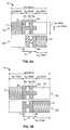
- FIG. 1shows a non-limiting side-view schematic of a sensor device, according to one embodiment of the present invention
- FIG. 2Ashows a non-limiting top-view schematic of the first and second fabric substrates, and corresponding first and second electrode materials disposed thereon, according to one embodiment of the present invention, wherein the sensor device is in the equilibrium (non-stretched) configuration;
- FIG. 2Bshows a non-limiting top-view schematic of the first and second fabric substrates, and corresponding first and second electrode materials disposed thereon, according to one embodiment of the present invention, wherein the sensor device is in the extended (stretched) configuration;
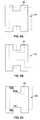
- FIG. 3Ashows a non-limiting top-view schematic of the first and second fabric substrates, and corresponding first and second electrode materials disposed thereon, according to one embodiment of the present invention, wherein the second electrode material comprises a pair of electrode portions arranged in a “comb” electrode pattern, and wherein the sensor device is in the equilibrium (non-stretched) configuration;
- FIG. 3Bshows a non-limiting top-view schematic of the first and second fabric substrates, and corresponding first and second electrode materials disposed thereon, according to one embodiment of the present invention, wherein the second electrode material comprises a pair of electrode portions arranged in a “comb” electrode pattern, and wherein the sensor device is in the extended (stretched) configuration;
- FIG. 4shows a non-limiting schematic of a transducer circuit in communication with the sensor device, according to one embodiment of the present invention
- FIG. 5shows a non-limiting schematic of a wearable article comprising a sensor device, according to one embodiment of the present invention, wherein the wearable article extends substantially about a subject's chest to monitor respiratory function;
- FIG. 6Ashows a non-limiting top-view schematic of the first and second fabric substrates, and corresponding first and second electrode materials disposed thereon, according to one embodiment of the present invention, wherein the second electrode material comprises a pair of interlocking electrode portions arranged in a “V” electrode pattern, and wherein the sensor device is in the equilibrium (non-stretched) configuration;
- FIG. 6Bshows a non-limiting top-view schematic of the first and second fabric substrates, and corresponding first and second electrode materials disposed thereon, according to one embodiment of the present invention, wherein the second electrode material comprises a pair of interlocking electrode portions arranged in a “V” electrode pattern, and wherein the sensor device is in the extended (stretched) configuration;
- FIG. 7shows a non-limiting schematic of a transducer circuit in communication with the sensor device comprising a differential capacitive sensor, according to one embodiment of the present invention
- FIGS. 8A-8Cshow non-limiting top view schematics of the first and second electrode materials, wherein the first electrode material includes a height that is larger than the corresponding height of the second electrode material such that the sensor device is capable of compensating for slight misalignment of the electrode materials in a direction substantially perpendicular to the selected direction; and
- FIG. 9shows a non-limiting plot of capacitance vs. extension in the selected direction for a sensor device according to one embodiment of the present invention, illustrating the substantial linearity of the capacitance vs. extension relationship of the sensor device.
- various embodiments of the present inventionare described herein in the context of a sensor system for monitoring motion, expansion and/or contraction that may be indicative of respiratory function, it should be understood that the various system embodiments described herein may also be used to monitor motion that may be indicative of other body functions and/or medical conditions.
- various sensor devices 1 and wearable articles described more fully hereinmay be used to monitor conditions that may include, but are not limited to: labor contractions in pregnancy; muscle spasms and/or contractions; joint motion and/or range of motion in extremities; and other conditions that may be monitored and/or assessed by the detection of movement, expansion, and/or contraction in a structure 100 about which a garment may be worn.
- various sensor device 1 embodiments described hereinmay be useful in monitoring respiration in a user and/or emitting an alert signal when respiratory function (and/or movement that is indicative thereof) ceases and/or significantly changes.
- various sensor device 1 embodiments described hereinmay be useful in a number of monitoring applications including, but not limited to: infant monitoring (to aid in the prevention of sudden infant death syndrome (SIDS)); ECG monitoring; motor vehicle driver monitoring; pilot monitoring; and/or patient monitoring in a clinical and/or home care setting.
- SIDSsudden infant death syndrome
- the various sensor device 1 embodiments described hereinutilize capacitive sensors to measure parameters related to movement of an anatomical structure (that may be indicative, for example, of respiratory function).
- the sensor device 1comprises a first electrode material 30 disposed on a first fabric substrate 10 and a second electrode material 40 disposed on a second fabric substrate 20 such that the first electrode material 30 and the second electrode material 40 are configured to cooperate to form a parallel plate capacitive sensor, as described further herein.
- a basic parallel plate capacitorutilizes a pair of electrical “plate” conductors (described herein as first and second electrode materials 30 , 40 , for example) arranged in parallel and separated by an air gap and/or a dielectric material (which, as described further herein, may comprise a spacer comprising an adhesive layer 31 , 41 disposed on one or more of the first and second electrode materials 30 , 40 ).
- the capacitance (C) of such a parallel plate capacitormay be expressed (in Farads (F)) by the following formula:
- Ais the plate area (i.e. the “overlap” in parallel plates (such as the overlap of the first and second electrode portions 30 , 40 , shown generally in FIG.
- dis the spacing between parallel plates (which may be determined, in some embodiments, by a thickness of a dielectric spacer material 31 , 41 disposed between the electrode plates); ⁇ is permittivity; ⁇ 0 is the dielectric constant for a vacuum (8.854 pF/m, for example); and ⁇ r is the relative dielectric constant (which may characterize the dielectric spacer material and/or materials 31 , 41 disposed between the electrode materials 30 , 40 of the parallel plate capacitor).
- changes in capacitance due to changes in the effective overlap area (A) of two electrode materials disposed on fabric substrates 10 , 20may be used to effectively measure movement in an anatomical structure 100 (see FIG. 5 , for example) that may be indicative of biological processes (such as respiration).
- some embodiments of the present inventionprovide a sensor device 1 adapted to be operably engaged with an anatomical structure 100 (see FIG. 5 , for example, showing a sensor device 1 operably engaged with and/or surrounding a torso and/or chest for assessing respiratory function).
- the sensor devicecomprises a first fabric substrate 10 comprising a first compliant portion 11 configured to stretch only in a selected direction 5 , and a first non-compliant portion 12 configured for providing a stable non-compliant surface on which an electrode material 30 , 40 may be applied.
- the sensor device 1may be configured such that as the compliant portions 11 , 21 stretch in the selected direction 5 , the electrode materials 30 , 40 forming a capacitive sensor may move generally towards each other such that the overlap area (and corresponding capacitance) of the two electrode portions 30 , 40 increases as the sensor device 1 is stretched and/or expanded.
- the sensor device 1may further comprise a second fabric substrate 20 , disposed substantially parallel to the first fabric substrate 10 such that the first and second fabric substrates 10 , 20 form parallel “layers” of a sensor device 1 that may be integrated into a wearable article (such as a compliant belt, for example, as shown in FIG. 5 ).
- the second fabric substrate 20may comprise a second compliant portion 21 configured to stretch only in the selected direction 5 , and a second non-compliant portion 22 configured for providing a second stable non-compliant surface on which an electrode material 30 , 40 may be applied.
- At least one of the first fabric substrate 10 and the second fabric substrate 20may comprise a non-woven fabric that may include, but is not limited to a hydroentangled mat of fibers.
- at least one of the first fabric substrate 10 and the second fabric substrate 20may comprise a woven fabric and/or some combination woven and non-woven fabrics.
- the compliant portions 11 , 21may be operably engaged with the non-compliant portions 12 , 22 in a substantially seamless lateral connection established, for example using an ultrasonic bonding process to form at least one of the first and second fabric substrates 10 , 20 .
- the compliant portions 11 , 21comprise fabric configured to stretch in substantially only one direction (such as the selected direction 5 , depicted generally in FIG. 1 ) such that any change in capacitance (C) in the sensor device 5 may be correlated directly to extension of the sensor (due to relative motion of the electrode portions 30 , 40 ) in the selected direction 5 .
- the non-compliant portions 12 , 22may comprise, in some embodiments, a substantially non-stretchable non-woven fabric comprising, for example a blend of 70% polyethylene terephthalate (PET) and 30% nylon.
- the sensor device 1may further comprise first and second electrode materials 30 , 40 disposed on the parallel fabric substrates 10 , 20 to form a parallel plate capacitor having a variable capacitance based on the change in overlap area A, that occurs as the relative positions of the electrode materials 30 , 40 change as the sensor device 1 stretches (i.e. due to inhalation when the sensor device 1 is operably engaged about a patient's chest 100 or other expanding and/or contracting structure (see FIG. 5 , for example)). As shown generally in FIG.
- the sensor device 1may comprise a first electrode material 30 disposed on the first non-compliant portion 12 and a second electrode material 40 disposed on the second non-compliant portion 22 such that the first electrode material 30 and the second electrode material 40 are configured to cooperate to form a parallel plate capacitive sensor having a variable capacitance corresponding to a relative motion of the first fabric substrate 10 and the second fabric substrate 20 as the anatomical structure 100 expands and/or contracts.
- the variable capacitancemay be configured to be variable in a substantially linear relationship to the relative motion of the first fabric substrate 10 and the second fabric substrate 20 as the anatomical structure 10 expands and stretches the sensor device 1 .
- At least one of the first electrode material 30 and the second electrode material 40may comprise a conductive material including, but not limited to: a conductive ink; a conductive foil; and combinations of such conductive materials.
- the conductive material used to print and/or prepare the electrode materials 30 , 40may include, but is not limited to: silver (such as, for example, silver ink CMI 112-15, commercially available from Creative Materials, Inc. of Tyngsboro, Mass.); gold; copper; aluminum; and/or combinations of such conductive materials.
- the conductive inkmay be screen printed on at least one of the first non-compliant portion 12 and the second non-compliant portion 22 in order to form the parallel plate capacitor structure shown generally in FIG. 1 (which, as described herein, may exhibit a linearly variable capacitance in relation to a stretch and/or relative displacement of the compliant portions 11 , 21 of the first and second fabric substrates 10 , 20 in the selected direction 5 ).
- some sensor device 1 embodimentsmay further comprise a first insulating layer 32 disposed between the first electrode material 30 and the first non-compliant portion 12 and a second insulating layer 42 disposed between the second electrode material 40 and the second non-compliant portion 22 .
- Such insulating layers 32 , 42may act to electrically insulate the outer surfaces of the parallel plate capacitor structure and may also be configured for coating the non-compliant portions 12 , 22 of the fabric substrates 10 , 20 such that conductive ink or other electrode materials 30 , 40 may be prevented from penetrating the fabric substrates 10 , 20 (the use of insulating layers 32 , 42 may be especially useful in sensor device 1 embodiments wherein the electrode materials 30 , 40 are screen printed on one or more of the first and second non-compliant portions 12 , 22 , respectively).
- the conductive foilmay be operably engaged with at least one of the first non-compliant portion 12 and the second non-compliant portion 22 using an adhesive coating (see elements 31 and 41 , respectively, for example) disposed on the conductive foil and overlapping onto at least a portion of at least one of the first non-compliant portion 12 and the second non-compliant portion 22 .
- at least one of the first and second electrode materials 30 , 40may comprise an aluminum foil attached to at least one of the non-compliant portions 12 , 22 using an adhesive over-layer.
- an adhesive over-layermay not only serve to adhere the electrode materials 30 , 40 to the non-compliant portions 12 , 22 of the fabric substrates 10 , 20 , but may also act as a dielectric spacing layer disposed between the parallel “plates” formed by the electrode materials 30 , 40 .
- the thickness of such a dielectric spacer material 31 , 41 disposed between the first electrode material 30 and the second electrode material 40may determine, for example, the distance (d) between the “plates” of the parallel plate capacitor that, in turn, may determine the capacitance output of the sensor device (see Equation (1) herein).
- the dielectric spacing material 31 , 41may comprise an adhesive coating (i.e. an “over-layer”) disposed on at least one of the first electrode material 30 and the second electrode material 40 .
- some sensor device 1 embodimentsmay further comprise a shield 50 disposed on a side of the first fabric substrate 10 opposite the first electrode material 30 .
- the shield 50may be configured for shielding at least one of the first electrode material 30 and the second electrode material 40 from one or more stray electric fields originating from outside the sensor device 1 .
- the sensor device 1may also comprise a shield 50 disposed on a side of the second fabric substrate 20 opposite the second electrode material 40 .
- the shield 50may also be configured to reduce “fringe” effects or “back plane” effects resulting from charge distributions (and resulting stray electric fields) on the “back side” (i.e.
- the linearity of the variable capacitance vs. stretch in the selected direction 5may be compromised due to fringe effects originating on portions of the electrode materials 30 , 40 that are not overlapping at any given point in the extension and/or retraction of the sensor device 1 .
- the shield 50may comprise, for example, a conductive electrode configured for modifying and/or negating the distorted electric fields created by the “fringe” and/or “back plane” effects so as to increase the linearity of the sensing range of the sensor device 1 .
- the shield 50may also serve to protect the electrode materials 30 , 40 from electrically-coupled noise.
- the shield 50in some sensor device 1 embodiments, may be placed in parallel with the first and second electrode materials 30 , 40 so as to “cover” the conductive electrode materials 30 , 40 of the sensor device 1 .
- the potential of the shield 50may be tied to electrical ground 3 and/or tied to a potential of one or more of the first and second electrode materials 30 , 40 via an operational amplifier (op-amp) 4 . More specifically, in some sensor device 1 embodiments, the shield 50 may be in communication with an electrical ground 3 . In other alternative sensor device 1 embodiments, the sensor device 1 may further comprise an op-amp 4 operably engaged between the shield 50 and at least one of the first and second electrode materials 30 , 40 .
- FIGS. 2A and 2Bshow a “top view” of the first and second fabric substrates 10 , 20 (and the first and second electrode materials 30 , 40 operably engaged with first and second non-compliant portions 12 , 22 , respectively) in both the equilibrium (non-stretched) ( FIG. 2A ) and the extended (stretched) ( FIG. 2B ) positions.
- the compliant portions 11 , 21 of the fabric substrates 10 , 20are configured for stretching only in the selected direction 5 .
- the overlap area (A) of the electrode materials 30 , 40is a function of the specific geometry of the electrode materials 30 , 40 and the stretched length of the sensor device 1 in the selected direction 5 .
- the shapes of the conductive areas 30 , 40may be designed to ensure that overlap of the electrode materials 30 , 40 (resulting in the area (A) of the parallel plate capacitor), varies substantially linearly with the stretched length of the sensor device 1 in the selected direction 5 , within the area limits of the sensor device 1 (denoted below as a minimum area (A min ) and a maximum area (A max )). For example, as shown in FIGS.
- the conductive areas 30 , 40 forming the “plates” of a variable-capacitance parallel plate capacitormay be screen printed or otherwise operably engaged with the fabric substrates 10 , 20 in a substantially “H-shape” pattern comprising “vertical bars” and connecting “horizontal bars.”
- the first electrode material 30 and the second electrode materials 40may be disposed on the corresponding non-compliant portion 12 , 22 in a corresponding at least one of a first H-shape and a second H-shape.
- the first and second H-shapesmay comprise at least a pair of vertical bars extending substantially perpendicularly to the selected direction 5 , the vertical bars including a width (w 4 , for example) and a height (h, for example).
- the H-shapesmay further comprise at least one horizontal bar extending substantially parallel to the selected direction 5 , the horizontal bar including a width (w 5 , for example) and a height (h 1 , for example).
- the sensor device 1 embodiments of the present inventionmay be designed to ensure that the capacitance (C) between the two electrode materials 30 , 40 increases substantially linearly (see FIG. 9 , for example) as the sensor device 1 stretches (due to the extension of the compliant portions 11 , 21 , for example) in the selected direction 5 .
- the width (w 4 , for example) of the vertical barsmay be substantially equivalent to a change in a length of the first and second compliant portions 11 , 21 when stretched substantially completely (see FIG. 2B , for example) in the selected direction 5 .
- the compliant portions 11 , 21are configured for stretching in length (i.e.
- the widths (w 4 , w 6 for example) of the vertical bars of the electrode materials 30 , 40should be set at 40% of the “at-rest” length (w 1 (see FIG. 2A )) of the compliant portions 11 , 21 to ensure substantially linear variations in capacitance.
- the width (w 5 , for example) of the horizontal bars (corresponding to spacing between the adjacent vertical bars)should also be set at 40% of the “at-rest” length (w 1 (see FIG. 2A )) of the compliant portions 11 , 21 .
- the corresponding width w 4 of the vertical barsshould be set at or about 2 cm to ensure linearity in the capacitance output of the sensor device 1 .
- the relative heights of the vertical and/or horizontal bars forming at least one of the first and second electrode materials 30 , 40may be greater than the corresponding height of the vertical bars and the height of the horizontal bars of the other of the first and second H-shapes such that the variable capacitance is variable in a substantially linear relationship to the relative motion of the first fabric substrate and the second fabric substrate as the anatomical structure expands.
- the heights of the vertical and horizontal bars making up the first H-shapemay be substantially about 50% larger that the corresponding heights of the vertical and horizontal bars making up the second H-shape.
- the heights of the vertical and horizontal bars making up the first H-shapemay be substantially about 100% larger that the corresponding heights of the vertical and horizontal bars making up the second H-shape.
- the height differential between the first and second electrode materials 30 , 40may allow the capacitance value generated by the sensor device 1 to remain substantially linear (see FIG. 9 , for example, showing an exemplary plot of capacitance (C) vs. extension of a sensor device 5 according to one embodiment) over the extension length in the selected direction 5 regardless of slight misalignment of the first and second electrode materials 30 , 40 in a direction that is substantially perpendicular to the selected direction 5 (i.e., the direction of extension).
- FIG. 9showing an exemplary plot of capacitance (C) vs. extension of a sensor device 5 according to one embodiment
- the shape of the electrode materials 30 , 40may be configured for providing a substantially equal variation in area (and corresponding variation in capacitance) regardless of slight misalignment of the electrode materials 30 , 40 in a direction substantially perpendicular to the selected direction 5 .
- the width (w 4 , w 6 ) of the “vertical bars” of the conductive materials 30 , 40 shown in FIGS. 2A and 2Bare assumed to be substantially equal. Because, the overlapping area (A) of the conductive materials 30 , 40 increases linearly along the selected direction 5 as the sensor device 1 is stretched (see FIG. 2B showing “full extension,” for example), the variations in linear capacitance (C) resulting from the changes in conductive area (A) (see Equation (2)) may be expressed as follows:
- ⁇is the permittivity of a dielectric spacer material 31 , 41 disposed between the electrode materials 30 , 40
- dis the distance between the electrode materials 30 , 40 forming the “plates” of the variable capacitance parallel plate capacitor.
- the variation in capacitance (C) of the sensor device 1may thus depend substantially only on the change in length of the sensor device 1 in the selected direction 5 and on the number of “vertical bars” or other area elements making up the area of the electrode materials 30 , 40 on the first and second non-compliant portions 12 , 22 of the fabric substrates 10 , 20 .
- the sensor device 1exhibits minimum capacitance when the sensor device 1 is in the equilibrium position (see FIG. 2A ).
- the dimensions of the conductive “horizontal bars” (h 1 ), orthogonal to the selected direction 5ensures in some embodiments, a minimum capacitance resulting from the “horizontal” portions of the electrode materials 30 , 40 regardless of the stretched length of the sensor device 1 .
- only those dimensions in the selected direction 5substantially change the capacitance of the sensor device 1 by altering the overlapping areas of the electrode materials 30 , 40 as the sensor device 1 stretches and/or relaxes to the equilibrium position (see FIG. 2A , for example).
- the exemplary embodiment of the sensor device 1 shown generally in FIGS. 2A and 2Bmay provide substantially the same capacitance output regardless of whether the applied stretching load (applied, for example, in the selected direction 5 ) is increasing (stretching) or decreasing (relaxing) along the selected direction 5 .
- the sensor device 1may be configured as a differential capacitive sensor.
- the first electrode material 30may comprise a first electrode portion 30 a and a second electrode portion 30 b such that the second electrode material 40 , the first electrode portion 30 a , and the second electrode portion 30 b are configured to cooperate to form a differential capacitive sensor having a variable capacitance established between the second electrode material 40 and at least one of the first electrode portion 30 a and the second electrode portion 30 b corresponding to the relative motion of the first fabric substrate 10 and the second fabric substrate 20 as the anatomical structure 100 expands and/or contracts.
- the first electrode portion 30 a and the second electrode portion 30 bmay be disposed in a substantially interlocking configuration to form a comb electrode.
- the first and second electrode portions 30 a , 30 bmay be disposed in a substantially interlocking “V” configuration on the first fabric substrate 10 .
- the differential capacitive sensor device 1 shown generally in FIGS. 3A , 3 B, 6 A, and 6 Bmay reduce potential static interference effects in a fabric-based sensor device 1 (that may arise, for example, from moisture and/or shrinkage of the fabric substrates 10 , 20 ).
- the sensor device 1comprises two separate variable capacitors as follows: (1) a first capacitor established between the second electrode material 40 and the first electrode portion 30 a ; and (2) a second capacitor established between the second electrode material 40 and the second electrode portion 30 b .
- the two variable capacitorsmay combine to “cancel out” interference effects as described herein.
- the second electrode material 40serves as a “pickup plate” that is movable laterally with respect to the two electrode portions 30 a , 30 b , such that the capacitance of each capacitor element varies equally whether the pickup plate moves to the left or to the right in the selected direction 5 .
- some differential capacitive sensor device 1 embodimentsmay comprise a first electrode material 30 divided into first and second electrode portions 30 a , 30 b disposed in an interlocking “comb” electrode configuration. As described further herein, such a “comb” configuration may provide a substantially linear capacitance versus extension curve due to the linear duplicated area change provided by the interlocking tines of the “comb.”
- at least one of the first electrode portion 30 a and the second electrode portion 30 bmay comprise at least two vertical bars extending substantially perpendicularly to the selected direction 5 ; and at least one horizontal bar extending substantially parallel to the selected direction 5 . As shown in FIGS.
- the at least one horizontal barmay be operably engaged between the at least two vertical bars to form a portion 30 a , 30 b of the comb electrode.
- the second electrode material 40may be disposed as a substantially rectangular frame on the second non-compliant portion 22 . As shown in FIG. 3A the substantially rectangular frame shape of the second electrode material 40 may define a substantially rectangular aperture therein. As described further herein, the resulting differential areas and corresponding differential capacitances in such embodiments are governed by the equations (5) through (9) listed herein.
- some differential capacitive sensor device 1 embodimentsmay comprise a first electrode material 30 divided into first and second electrode portions 30 a , 30 b disposed in an interlocking “V” electrode configuration.
- the interlocking “V” formed by the first and second electrode portions 30 a , 30 bmay provide a more consistent space and/or distance (d) between the pickup plate (embodied herein as the second electrode material 40 ) and the two electrode portions 30 a , 30 b .
- Some differential capacitive sensor embodimentsconsist of two variable parallel plate capacitors comprising: (1) a first capacitor defined between elements 30 a and 40 and; (2) a second capacitor defined between elements 30 b and 40 .
- These capacitorsare arranged such that they provide the same variation in capacitance regardless of which direction the fabric substrates 10 , 20 move relative to one another during a stretching and/or relaxation cycle of the overall sensor device 1 structure. For example, as shown in FIGS. 3A and 3B , if the second electrode material 40 moves laterally with respect to the first and second electrode portions 30 a and 30 b then the capacitance of each capacitor portion varies equally whether it moves to the right or to the left in the selected direction 5 .
- a 30b( N+ 1) w 4 h 2 +N ( w 4 ⁇ w ′) h 1 (5)
- a 30a( N+ 1) w 4 h 2 +Nw′h 1
- w′refers to the stretched length of the sensor device 1 .
- the overlapping areas (A) for each capacitor portionchange between minimum and maximum (A min and A max ) area values as the sensor device 1 expands and contracts.
- the minimum and maximum area valuesmay be expressed as:
- a min( N+ 1) w 4 h 2 (6)
- a max( N+ 1) w 4 h 2 +Nw 4 h 1 Therefore, referring to Equation (1), the corresponding capacitances (C) may be expressed as:
- each capacitor portion formed by each corresponding electrode portion 30 a and 30 bmay be expressed as:
- some sensor device 1 embodimentsmay further comprise a transducer circuit 400 in communication with the parallel plate capacitive sensor.
- the transducer circuit 400may be configured for converting the variable capacitance into corresponding variable voltage indicative of the expansion and/or contraction of the anatomical structure 100 .
- the transducer circuit 400may be configured for conditioning waveforms, for example respiratory function signals, being generated by the sensor device 1 .
- the sensor device 1may be configured for operably engaging (i.e. wrapping substantially about) an anatomical structure 100 such as a patient's torso or chest.
- the transducer circuit 400may be configured for converting the variable voltage into an indication of respiratory function corresponding to the expansion and/or contraction of the torso 100 .
- the transducer circuit 400may comprise an RLC “tank” oscillator or other detector circuit 401 configured for converting the variable capacitance into a corresponding frequency shift.
- the detector circuit 401may comprise, for example, a CMOS 7555 timer with a resistor R and capacitor C wherein the output frequency may be characterized as 1/RC and the duty cycle is substantially about 50%.
- the transducer circuit 400may further comprise a buffer amplifier 402 in communication between the detector circuit 401 and the load (see elements 403 - 406 , for example) to ensure that the output frequency of the detector circuit 401 is substantially stable.
- the transducer circuit 400(as shown, for example, in FIG.
- the transducer circuit 400may further comprise an FM demodulator 403 configured for detecting the frequency shift output of the detector circuit 401 .
- the transducer circuit 400further comprises a low-pass filter (LPF) 404 and a differential amplifier (with gain) 405 configured for maintaining substantially flat transducer circuit 400 output signal when the sensor device 1 detects a cessation in structure function (as indicated by a lack of relative movement of the electrode materials 30 , 40 within the sensor device 1 ).
- the transducer circuit 400may also comprise a second LPF 406 configured for removing unwanted noise through the signal track that may interfere with the signal sent to an alarm or other monitoring user interface 500 (see FIG. 5 , for example).
- the transducer circuit 400may be modified for conditioning a differential capacitance signal into a detectable output signal.
- the transducer circuit 400may comprise an analog capacitive voltage divider circuit 701 configured for generating output signals having amplitudes that are controlled by the dual capacitances generated by the differential capacitive sensor (comprising, the second electrode material 40 and the first and second electrode portions 30 a , 30 b ).
- the transducer circuit 400further comprises a buffer amplifier 702 in communication between the capacitive voltage divider circuit 701 and the load (see elements 703 - 707 , for example).
- the transducer circuitmay also comprise an amplifier 703 configured to provide an amplified output to an envelope detector circuit 704 (which may comprise, in some embodiments, a half-wave rectifier, configured for extract amplitude levels of the AC signal generated by the sensor device 1 .
- the transducer circuit 400may also comprise a differential amplifier 705 configured for comparing the envelope signal (the output of the envelope detector circuit 704 , for example) to a reference voltage 706 .
- the transducer circuitmay also comprise an LPF 707 (such as a 2 nd Order Sallen-Key LPF, for example) configured for filtering high-frequency noise from the output signal of the transducer circuit 400 .
- the sensor device 100may comprise a substantially flexible belt or strap that may be in wired and/or wireless communication with the transducer circuit 400 (and/or a processor device comprising various components of the transducer circuit 400 (as shown in FIG. 4 , for example).
- the transducer circuit 400may be in further communication with a user interface 500 configured for displaying a visual indication of structure function and/or an audible indication when the parameter being measures drifts out of range.
- the sensor device 1may be in communication with the transducer circuit 400 which may, in turn, be in communication with a user interface 500 configured for generating an audible alarm when motion detected by the sensor device 1 indicates a substantial pause in respiratory function and/or a significant reduction in respiratory rate and/or intensity.
- the various sensor device 1 embodiments of the present inventionprovide a stable, accurate, and substantially linear capacitive sensor that may be directly integrated into wearable articles that may be worn by a patient being monitored.
- the sensor device 1may be unobtrusively worn by a patient or subject without the need for electrodes or other transducer components to be adhered to the skin.
- the first fabric substrate 10 and the second fabric substrate 20may be formed into various fabric layers of a wearable article such that as the article stretches in the selected direction 5 (see FIG. 5 , for example) the sensor device 1 integrated therein may accurately and precisely detect a substantially linear change in capacitance (C) experienced by the sensor device 1 as it stretches and/or relaxes.
- Ccapacitance
- the wearable articlemay include, but is not limited to: a belt extending substantially about the anatomical structure (see FIG. 5 , for example); a shirt; a bandage comprising at least one adhesive material disposed thereon for operably engaging the bandage with the anatomical structure; and combinations of such wearable articles.
- FIG. 9shows simulation results for two separate sensor device 1 designs.
- curve 920shows a plot of capacitance (in picoFarads) versus extension (in cm) of a sensor device 1 such as that shown generally in FIGS. 2A and 2B .
- curve 910shows a plot of capacitance (in picoFarads) versus extension (in cm) of a sensor device 1 such as that shown in FIGS. 8A-8C wherein one of the electrode materials 30 , 40 is characterized by a larger height of the vertical and horizontal bars making up an “H-shape” electrode configuration.
- the output capacitance for both embodimentsincreases in a substantially linear relationship to the extension of the sensor device 1 .
- this embodimentmay also be more likely to provide a capacitance output that is generally more sensitive to changes in extension. This result is shown, for example, by comparing the plots 910 and 920 .
- the sensor device 1 design of FIGS. 2A and 2B(the response of which is shown in plot 920 ) generates generally more capacitance output but with less sensitivity to changes in extension of the sensor device 1 .
- this resultmay be due to the fact that the electrode material 30 , 40 design of FIG. 2A has less overlapped area between the first and second electrode materials 30 , 40 and therefore somewhat less “room for error” when adapting to misalignment of the electrode materials 30 , 40 in a direction substantially perpendicular to the selected direction 5 of extension.
- the present inventionalso provides various method embodiments for measuring respiratory function.
- one such method embodimentcomprises a step for engaging a pair of electrodes 30 , 40 with an overlapping pair of fabric substrates 10 , 20 to form a sensor device 1 comprising a parallel plate capacitor.
- each of the fabric substrates 10 , 20may comprise a compliant portion 11 , 21 configured for stretching only in a selected direction.
- the methodfurther comprises wrapping the sensor device 1 substantially about an anatomical structure 100 (such as a patient's chest, for example, as shown generally in FIG. 5 ).
- the methodfurther comprises steps for: sensing a change in capacitance in the parallel plate capacitor corresponding to stretching of the compliant portions 11 , 21 due at least in part to an expansion and/or contraction of the anatomical structure 100 ; and converting the sensed change in capacitance to a signal indicative of the respiratory function, using a processing element (such as a circuit 400 (see FIGS. 4 and 6 , for example) in communication with the sensor device 1 .
- a processing elementsuch as a circuit 400 (see FIGS. 4 and 6 , for example) in communication with the sensor device 1 .
Landscapes
- Health & Medical Sciences (AREA)
- Life Sciences & Earth Sciences (AREA)
- Physics & Mathematics (AREA)
- Molecular Biology (AREA)
- Animal Behavior & Ethology (AREA)
- Pathology (AREA)
- Engineering & Computer Science (AREA)
- Biomedical Technology (AREA)
- Heart & Thoracic Surgery (AREA)
- Medical Informatics (AREA)
- Veterinary Medicine (AREA)
- Surgery (AREA)
- Biophysics (AREA)
- General Health & Medical Sciences (AREA)
- Public Health (AREA)
- General Physics & Mathematics (AREA)
- Physiology (AREA)
- Dentistry (AREA)
- Oral & Maxillofacial Surgery (AREA)
- Measurement Of The Respiration, Hearing Ability, Form, And Blood Characteristics Of Living Organisms (AREA)
Abstract
Description
Wherein, A is the plate area (i.e. the “overlap” in parallel plates (such as the overlap of the first and
Avar=(N+1)w4h1+Nw′(h−h1)
Amin=(N+1)w4h1 (2)
Amax=(N+1)w4h1+Nw4(h−h1)
Where N indicates the number of “vertical bars” in the overlapping sensor area (A), and where w′ is the maximum “stretched” length of the
Where ε is the permittivity of a
The exemplary embodiment of the
A30b=(N+1)w4h2+N(w4−w′)h1 (5)
A30a=(N+1)w4h2+Nw′h1
It should be understood that w′ refers to the stretched length of the
Amin=(N+1)w4h2 (6)
Amax=(N+1)w4h2+Nw4h1
Therefore, referring to Equation (1), the corresponding capacitances (C) may be expressed as:
Where d is the distance between the
As can be seen when reviewing Equations (8) in light of
Claims (33)
Priority Applications (1)
| Application Number | Priority Date | Filing Date | Title |
|---|---|---|---|
| US11/681,329US7712373B2 (en) | 2006-03-03 | 2007-03-02 | Sensor device for real-time monitoring or relative movement using capacitive fabric sensors |
Applications Claiming Priority (2)
| Application Number | Priority Date | Filing Date | Title |
|---|---|---|---|
| US74340406P | 2006-03-03 | 2006-03-03 | |
| US11/681,329US7712373B2 (en) | 2006-03-03 | 2007-03-02 | Sensor device for real-time monitoring or relative movement using capacitive fabric sensors |
Publications (2)
| Publication Number | Publication Date |
|---|---|
| US20080000304A1 US20080000304A1 (en) | 2008-01-03 |
| US7712373B2true US7712373B2 (en) | 2010-05-11 |
Family
ID=38875231
Family Applications (1)
| Application Number | Title | Priority Date | Filing Date |
|---|---|---|---|
| US11/681,329Expired - Fee RelatedUS7712373B2 (en) | 2006-03-03 | 2007-03-02 | Sensor device for real-time monitoring or relative movement using capacitive fabric sensors |
Country Status (1)
| Country | Link |
|---|---|
| US (1) | US7712373B2 (en) |
Cited By (64)
| Publication number | Priority date | Publication date | Assignee | Title |
|---|---|---|---|---|
| US20080164888A1 (en)* | 2006-12-22 | 2008-07-10 | Yamaha Corporation | Electrostatic capacity sensor |
| US20090165572A1 (en)* | 2007-12-27 | 2009-07-02 | Divyasimha Harish | Microelectromechanical capacitive device |
| US20090248194A1 (en)* | 2008-03-26 | 2009-10-01 | Haas Automation, Inc. | Cut optimization system and method |
| US20100113910A1 (en)* | 2007-04-24 | 2010-05-06 | Koninklijke Philips Electronics N.V. | Sensor arrangement and method for monitoring physiological parameters |
| US20110008919A1 (en)* | 2007-01-29 | 2011-01-13 | Board Of Regents, The University Of Texas System | Electronic Textiles with Electronic Devices on Ribbons |
| US20110023631A1 (en)* | 2009-08-03 | 2011-02-03 | Peter Sleeman | Force sensor with compressible electrode |
| US20110092125A1 (en)* | 2007-01-29 | 2011-04-21 | Board Of Regents, The University Of Texas System | Testing Electronic Textiles During Assembly and Electronic Textile Displays |
| WO2013033238A1 (en)* | 2011-09-01 | 2013-03-07 | Zoll Medical Corporation | Wearable monitoring and treatment device |
| US20130056354A1 (en)* | 2011-09-07 | 2013-03-07 | Chen-Pang Kung | Sensing device and sensing method for sensing multiple dimensional force |
| US8600486B2 (en) | 2011-03-25 | 2013-12-03 | Zoll Medical Corporation | Method of detecting signal clipping in a wearable ambulatory medical device |
| US20130342225A1 (en)* | 2011-03-11 | 2013-12-26 | Uster Technologies Ag | Capacitive Analysis of a Moving Test Material |
| US8774917B2 (en) | 2007-06-06 | 2014-07-08 | Zoll Medical Corporation | Wearable defibrillator with audio input/output |
| US8897860B2 (en) | 2011-03-25 | 2014-11-25 | Zoll Medical Corporation | Selection of optimal channel for rate determination |
| US8945328B2 (en) | 2012-09-11 | 2015-02-03 | L.I.F.E. Corporation S.A. | Methods of making garments having stretchable and conductive ink |
| US8948839B1 (en) | 2013-08-06 | 2015-02-03 | L.I.F.E. Corporation S.A. | Compression garments having stretchable and conductive ink |
| US9135398B2 (en) | 2011-03-25 | 2015-09-15 | Zoll Medical Corporation | System and method for adapting alarms in a wearable medical device |
| US9215989B2 (en) | 2010-05-18 | 2015-12-22 | Zoll Medical Corporation | Wearable ambulatory medical device with multiple sensing electrodes |
| US9282893B2 (en) | 2012-09-11 | 2016-03-15 | L.I.F.E. Corporation S.A. | Wearable communication platform |
| US9322121B2 (en) | 2013-02-28 | 2016-04-26 | Regents Of The University Of Minnesota | Stitched stretch sensor |
| WO2017020111A1 (en)* | 2015-08-05 | 2017-02-09 | Chahine Tony | Garment with stretch sensors |
| US9579516B2 (en) | 2013-06-28 | 2017-02-28 | Zoll Medical Corporation | Systems and methods of delivering therapy using an ambulatory medical device |
| US9597523B2 (en) | 2014-02-12 | 2017-03-21 | Zoll Medical Corporation | System and method for adapting alarms in a wearable medical device |
| US9684767B2 (en) | 2011-03-25 | 2017-06-20 | Zoll Medical Corporation | System and method for adapting alarms in a wearable medical device |
| US9782096B2 (en) | 2011-01-31 | 2017-10-10 | Clothing Plus Mbu Oy | Textile substrate for measuring physical quantity |
| US9817440B2 (en) | 2012-09-11 | 2017-11-14 | L.I.F.E. Corporation S.A. | Garments having stretchable and conductive ink |
| US9814894B2 (en) | 2012-05-31 | 2017-11-14 | Zoll Medical Corporation | Systems and methods for detecting health disorders |
| US9878171B2 (en) | 2012-03-02 | 2018-01-30 | Zoll Medical Corporation | Systems and methods for configuring a wearable medical monitoring and/or treatment device |
| US10154791B2 (en) | 2016-07-01 | 2018-12-18 | L.I.F.E. Corporation S.A. | Biometric identification by garments having a plurality of sensors |
| US10159440B2 (en) | 2014-03-10 | 2018-12-25 | L.I.F.E. Corporation S.A. | Physiological monitoring garments |
| US10172423B2 (en) | 2016-03-15 | 2019-01-08 | Nike, Inc. | Capacitive foot presence sensing devices for footwear |
| US20190041281A1 (en)* | 2016-02-06 | 2019-02-07 | Shenzhen New Degree Technology Co., Ltd. | Pressure sensor, electronic device, and method for manufacturing pressure sensor |
| US10201711B2 (en) | 2014-12-18 | 2019-02-12 | Zoll Medical Corporation | Pacing device with acoustic sensor |
| US10201310B2 (en) | 2012-09-11 | 2019-02-12 | L.I.F.E. Corporation S.A. | Calibration packaging apparatuses for physiological monitoring garments |
| US10252070B2 (en) | 2015-09-08 | 2019-04-09 | Zoll Medical Corporation | Secure limited components for use with medical devices |
| US10272010B2 (en) | 2015-03-20 | 2019-04-30 | Zoll Medical Corporation | Systems and methods for testing a medical device |
| US10321877B2 (en) | 2015-03-18 | 2019-06-18 | Zoll Medical Corporation | Medical device with acoustic sensor |
| US10426342B2 (en) | 2016-03-31 | 2019-10-01 | Zoll Medical Corporation | Remote access for ambulatory medical device |
| US10462898B2 (en) | 2012-09-11 | 2019-10-29 | L.I.F.E. Corporation S.A. | Physiological monitoring garments |
| US10467744B2 (en) | 2014-01-06 | 2019-11-05 | L.I.F.E. Corporation S.A. | Systems and methods to automatically determine garment fit |
| US10493289B2 (en) | 2010-07-09 | 2019-12-03 | Zoll Medical Corporation | System and method for conserving power in a medical device |
| US10602945B2 (en) | 2018-03-13 | 2020-03-31 | Zoll Medical Corporation | Telemetry of wearable medical device information to secondary medical device or system |
| US10646707B2 (en) | 2017-11-30 | 2020-05-12 | Zoll Medical Corporation | Medical devices with rapid sensor recovery |
| US10653190B2 (en) | 2012-09-11 | 2020-05-19 | L.I.F.E. Corporation S.A. | Flexible fabric ribbon connectors for garments with sensors and electronics |
| US10674911B2 (en) | 2016-03-30 | 2020-06-09 | Zoll Medical Corporation | Systems and methods of integrating ambulatory medical devices |
| US20200256748A1 (en)* | 2019-02-07 | 2020-08-13 | Korea University Research And Business Foundation | Strain sensor and method of fabricating the same |
| US10835449B2 (en) | 2015-03-30 | 2020-11-17 | Zoll Medical Corporation | Modular components for medical devices |
| US10842413B2 (en) | 2019-04-19 | 2020-11-24 | National Taiwan University | Piezoelectric patch sensor |
| US10918877B2 (en) | 2018-09-28 | 2021-02-16 | Zoll Medical Corporation | Battery lock for ambulatory medical device |
| US10932726B2 (en) | 2018-03-16 | 2021-03-02 | Zoll Medical Corporation | Monitoring physiological status based on bio-vibrational and radio frequency data analysis |
| US10939840B2 (en) | 2014-09-23 | 2021-03-09 | Rr Sequences Inc. | Contactless electric cardiogram system |
| US10960213B2 (en) | 2018-03-12 | 2021-03-30 | Zoll Medical Corporation | Verification of cardiac arrhythmia prior to therapeutic stimulation |
| US11026481B2 (en) | 2016-03-15 | 2021-06-08 | Nike, Inc. | Foot presence signal processing using velocity |
| US11064768B2 (en) | 2016-03-15 | 2021-07-20 | Nike, Inc. | Foot presence signal processing using velocity |
| US11213691B2 (en) | 2017-02-27 | 2022-01-04 | Zoll Medical Corporation | Ambulatory medical device interaction |
| US11246213B2 (en) | 2012-09-11 | 2022-02-08 | L.I.F.E. Corporation S.A. | Physiological monitoring garments |
| US11291409B2 (en) | 2014-12-03 | 2022-04-05 | Clothing Plus Mbu Oy | Device for determining effects of aging of a wearable device |
| US11357290B2 (en) | 2016-03-15 | 2022-06-14 | Nike, Inc. | Active footwear sensor calibration |
| US11494147B2 (en) | 2019-06-26 | 2022-11-08 | Microsoft Technology Licensing, Llc | Sensing bending of multiple joints |
| US11568984B2 (en) | 2018-09-28 | 2023-01-31 | Zoll Medical Corporation | Systems and methods for device inventory management and tracking |
| US11617538B2 (en) | 2016-03-14 | 2023-04-04 | Zoll Medical Corporation | Proximity based processing systems and methods |
| US11709747B2 (en) | 2016-01-08 | 2023-07-25 | Zoll Medical Corporation | Patient assurance system and method |
| US11942222B2 (en) | 2018-06-18 | 2024-03-26 | Zoll Medical Corporation | Medical device for estimating risk of patient deterioration |
| US12185630B2 (en) | 2019-08-09 | 2024-12-31 | Apple Inc. | Layered sensor having multiple laterally adjacent substrates in a single layer |
| US12191030B2 (en) | 2014-07-07 | 2025-01-07 | Zoll Medical Corporation | Medical device with natural language processor |
Families Citing this family (41)
| Publication number | Priority date | Publication date | Assignee | Title |
|---|---|---|---|---|
| WO2005032447A2 (en)* | 2003-08-22 | 2005-04-14 | Foster-Miller, Inc. | Physiological monitoring garment |
| US7644628B2 (en)* | 2005-12-16 | 2010-01-12 | Loadstar Sensors, Inc. | Resistive force sensing device and method with an advanced communication interface |
| US20070299325A1 (en)* | 2004-08-20 | 2007-12-27 | Brian Farrell | Physiological status monitoring system |
| IL186768A0 (en)* | 2007-10-18 | 2008-02-09 | Shaked Rahamim | Infant apnea detector and system |
| KR101051311B1 (en)* | 2008-04-22 | 2011-07-22 | 한국과학기술원 | Textile Input Device |
| CN102036600B (en)* | 2008-05-23 | 2014-08-06 | 皇家飞利浦电子股份有限公司 | Substrate layer suitable for carrying sensors, actuators or electronic components |
| WO2011054548A1 (en)* | 2009-11-05 | 2011-05-12 | Siemens Aktiengesellschaft | Respiration measurement sensor |
| JP5170907B2 (en)* | 2010-01-11 | 2013-03-27 | 日本特殊陶業株式会社 | Control device for controlled parts for vehicles |
| US9211085B2 (en)* | 2010-05-03 | 2015-12-15 | Foster-Miller, Inc. | Respiration sensing system |
| US9028404B2 (en) | 2010-07-28 | 2015-05-12 | Foster-Miller, Inc. | Physiological status monitoring system |
| US8585606B2 (en) | 2010-09-23 | 2013-11-19 | QinetiQ North America, Inc. | Physiological status monitoring system |
| KR20120057295A (en)* | 2010-11-26 | 2012-06-05 | 한국전자통신연구원 | The Non-intrusive wearable respiratory failure alarming apparatus and method thereof |
| US8827930B2 (en) | 2011-01-10 | 2014-09-09 | Bioguidance Llc | System and method for patient monitoring |
| US8915869B2 (en) | 2011-01-10 | 2014-12-23 | Bioguidance Llc | Patient monitoring device |
| US20150257970A1 (en)* | 2011-02-17 | 2015-09-17 | Martin Mücke | Device and method for reducing pain |
| CN104219999A (en)* | 2012-01-30 | 2014-12-17 | 感官系统公司 | Sensors, interfaces and sensor systems for data collection and integrated remote monitoring of conditions at or near body surfaces |
| CN102670205B (en)* | 2012-03-31 | 2014-01-15 | 天津九安医疗电子股份有限公司 | Infant height measuring device |
| EP2914165B1 (en)* | 2012-09-07 | 2017-08-09 | The Regents of the University of California | Multisensor abdominal monitoring system |
| KR20150110570A (en)* | 2013-01-08 | 2015-10-02 | 엠씨10, 인크 | Application for monitoring a property of a surface |
| US9037221B2 (en)* | 2013-01-16 | 2015-05-19 | University Of Rochester | Non-contact electrocardiogram system |
| US20140228657A1 (en) | 2013-02-09 | 2014-08-14 | Spire, Inc. | System and method for monitoring respiration |
| CN103271736A (en)* | 2013-05-06 | 2013-09-04 | 无锡交大联云科技有限公司 | Flexible capacitive electrocardio dry electrode and manufacturing method thereof |
| WO2014204323A1 (en)* | 2013-06-17 | 2014-12-24 | Stretchsense Limited | Stretchable fabric sensors |
| WO2014202135A1 (en)* | 2013-06-19 | 2014-12-24 | Siemens Aktiengesellschaft | A system and a method for determining physiological movements of a subject |
| CN104282250B (en)* | 2014-10-24 | 2016-08-31 | 深圳市华星光电技术有限公司 | In TFT MIS structure design control method and system |
| CN104720810A (en)* | 2014-12-16 | 2015-06-24 | 张紫豪 | Capacitive type respiratory wave detecting device |
| JP6665186B2 (en)* | 2014-12-22 | 2020-03-13 | コーニンクレッカ フィリップス エヌ ヴェKoninklijke Philips N.V. | Method and apparatus for providing an alarm |
| CN104900407B (en)* | 2015-04-16 | 2018-02-13 | 王卫东 | Capacitor for respiratory volume kinescope |
| US9642580B2 (en) | 2015-08-26 | 2017-05-09 | General Electric Company | Monitoring device including compliant variable capacitor for respiration and cardiac sensing applications |
| US10993660B2 (en) | 2017-02-07 | 2021-05-04 | Spire, Inc. | System for physiological monitoring |
| WO2018174730A1 (en)* | 2017-03-23 | 2018-09-27 | Stretchsense Limited | Sensing over a shared physical channel |
| US10180721B2 (en)* | 2017-06-14 | 2019-01-15 | Apple Inc. | Fabric-based devices with force sensing |
| EP3473976B1 (en) | 2017-10-20 | 2019-09-25 | C.R.F. Società Consortile per Azioni | Deformation detecting device comprising a multi-functional fabric with flocked conductive weft yarns |
| US11173373B2 (en)* | 2018-01-04 | 2021-11-16 | Adidas Ag | Athletic monitoring garment with non-transmitting, non-receiving sensor systems and methods |
| US10937298B2 (en)* | 2018-04-11 | 2021-03-02 | Shawn NEVIN | Occupant monitoring system and method |
| EP3586743A1 (en)* | 2018-06-29 | 2020-01-01 | Nokia Technologies Oy | Method and apparatus for determining information regarding body position |
| GB201811050D0 (en)* | 2018-07-05 | 2018-08-22 | Ergo Figure Ltd | A measurement device |
| CN109916284A (en)* | 2019-03-01 | 2019-06-21 | 维沃移动通信有限公司 | A position detection method and terminal device |
| US20220061699A1 (en)* | 2020-08-31 | 2022-03-03 | Apple Inc. | Flexible Capacitive Sensing Mat Including Spacer Fabric |
| US11680786B2 (en)* | 2021-11-05 | 2023-06-20 | Waymo Llc | Capacitive position sensing for camera focus management |
| US12401874B2 (en)* | 2023-09-27 | 2025-08-26 | Apple Inc. | Electrostatic brakes for camera modules |
Citations (11)
| Publication number | Priority date | Publication date | Assignee | Title |
|---|---|---|---|---|
| US4790968A (en) | 1985-10-19 | 1988-12-13 | Toshiba Silicone Co., Ltd. | Process for producing pressure-sensitive electroconductive sheet |
| US5137842A (en)* | 1991-05-10 | 1992-08-11 | Micron Technology, Inc. | Stacked H-cell capacitor and process to fabricate same |
| US5371657A (en) | 1993-09-13 | 1994-12-06 | Tenco Partnership | Pliable illuminated fabric articles |
| US5371326A (en) | 1993-08-31 | 1994-12-06 | Clearwaters-Dreager; Cindy | Non-toxic fabric conductors and method for making same |
| US6037621A (en)* | 1998-07-29 | 2000-03-14 | Lucent Technologies Inc. | On-chip capacitor structure |
| US6311350B1 (en) | 1999-08-12 | 2001-11-06 | Ferber Technologies, L.L.C. | Interactive fabric article |
| US6826968B2 (en)* | 2000-11-28 | 2004-12-07 | Stmicroelectronics S.R.L. | Textile-like capacitive pressure sensor and method of mapping the pressure exerted at points of a surface of a flexible and pliable object, particularly of a sail |
| US7047818B2 (en)* | 2003-04-09 | 2006-05-23 | Loadstar Sensors, Inc. | Capacitive force sensing device |
| WO2007056557A1 (en) | 2005-11-08 | 2007-05-18 | North Carolina State University | Methods and devices for providing flexible electronics |
| US7299083B2 (en)* | 2004-12-09 | 2007-11-20 | Signalife, Inc. | Electrode for, and method of, indicating signal characteristics at particular positions in a patient's body |
| US7353713B2 (en)* | 2003-04-09 | 2008-04-08 | Loadstar Sensors, Inc. | Flexible apparatus and method to enhance capacitive force sensing |
- 2007
- 2007-03-02USUS11/681,329patent/US7712373B2/ennot_activeExpired - Fee Related
Patent Citations (11)
| Publication number | Priority date | Publication date | Assignee | Title |
|---|---|---|---|---|
| US4790968A (en) | 1985-10-19 | 1988-12-13 | Toshiba Silicone Co., Ltd. | Process for producing pressure-sensitive electroconductive sheet |
| US5137842A (en)* | 1991-05-10 | 1992-08-11 | Micron Technology, Inc. | Stacked H-cell capacitor and process to fabricate same |
| US5371326A (en) | 1993-08-31 | 1994-12-06 | Clearwaters-Dreager; Cindy | Non-toxic fabric conductors and method for making same |
| US5371657A (en) | 1993-09-13 | 1994-12-06 | Tenco Partnership | Pliable illuminated fabric articles |
| US6037621A (en)* | 1998-07-29 | 2000-03-14 | Lucent Technologies Inc. | On-chip capacitor structure |
| US6311350B1 (en) | 1999-08-12 | 2001-11-06 | Ferber Technologies, L.L.C. | Interactive fabric article |
| US6826968B2 (en)* | 2000-11-28 | 2004-12-07 | Stmicroelectronics S.R.L. | Textile-like capacitive pressure sensor and method of mapping the pressure exerted at points of a surface of a flexible and pliable object, particularly of a sail |
| US7047818B2 (en)* | 2003-04-09 | 2006-05-23 | Loadstar Sensors, Inc. | Capacitive force sensing device |
| US7353713B2 (en)* | 2003-04-09 | 2008-04-08 | Loadstar Sensors, Inc. | Flexible apparatus and method to enhance capacitive force sensing |
| US7299083B2 (en)* | 2004-12-09 | 2007-11-20 | Signalife, Inc. | Electrode for, and method of, indicating signal characteristics at particular positions in a patient's body |
| WO2007056557A1 (en) | 2005-11-08 | 2007-05-18 | North Carolina State University | Methods and devices for providing flexible electronics |
Cited By (174)
| Publication number | Priority date | Publication date | Assignee | Title |
|---|---|---|---|---|
| US20080164888A1 (en)* | 2006-12-22 | 2008-07-10 | Yamaha Corporation | Electrostatic capacity sensor |
| US20110097960A1 (en)* | 2007-01-29 | 2011-04-28 | Board Of Regents, The University Of Texas System | Testing Electronic Textiles During Assembly and Electronic Textile Displays |
| US8302302B2 (en) | 2007-01-29 | 2012-11-06 | Board Of Regents, The University Of Texas System | Method of manufacturing resistance film heating apparatus |
| US20110008919A1 (en)* | 2007-01-29 | 2011-01-13 | Board Of Regents, The University Of Texas System | Electronic Textiles with Electronic Devices on Ribbons |
| US20110092125A1 (en)* | 2007-01-29 | 2011-04-21 | Board Of Regents, The University Of Texas System | Testing Electronic Textiles During Assembly and Electronic Textile Displays |
| US8404527B2 (en) | 2007-01-29 | 2013-03-26 | The Board Of Regents, The University Of Texas System | Electronic textiles with electronic devices on ribbons |
| US8381396B2 (en) | 2007-01-29 | 2013-02-26 | Board Of Regents, The University Of Texas System | Method of assembling a textile display |
| US20100113910A1 (en)* | 2007-04-24 | 2010-05-06 | Koninklijke Philips Electronics N.V. | Sensor arrangement and method for monitoring physiological parameters |
| US8583206B2 (en)* | 2007-04-24 | 2013-11-12 | Koninklijke Philips N.V. | Sensor arrangement and method for monitoring physiological parameters |
| US8774917B2 (en) | 2007-06-06 | 2014-07-08 | Zoll Medical Corporation | Wearable defibrillator with audio input/output |
| US11083886B2 (en) | 2007-06-06 | 2021-08-10 | Zoll Medical Corporation | Wearable defibrillator with audio input/output |
| US10426946B2 (en) | 2007-06-06 | 2019-10-01 | Zoll Medical Corporation | Wearable defibrillator with audio input/output |
| US9492676B2 (en) | 2007-06-06 | 2016-11-15 | Zoll Medical Corporation | Wearable defibrillator with audio input/output |
| US10004893B2 (en) | 2007-06-06 | 2018-06-26 | Zoll Medical Corporation | Wearable defibrillator with audio input/output |
| US10029110B2 (en) | 2007-06-06 | 2018-07-24 | Zoll Medical Corporation | Wearable defibrillator with audio input/output |
| US8965500B2 (en) | 2007-06-06 | 2015-02-24 | Zoll Medical Corporation | Wearable defibrillator with audio input/output |
| US12138444B2 (en) | 2007-06-06 | 2024-11-12 | Zoll Medical Corporation | Wearable defibrillator with audio input/output |
| US7980145B2 (en)* | 2007-12-27 | 2011-07-19 | Y Point Capital, Inc | Microelectromechanical capacitive device |
| US20090165572A1 (en)* | 2007-12-27 | 2009-07-02 | Divyasimha Harish | Microelectromechanical capacitive device |
| US8954185B2 (en)* | 2008-03-26 | 2015-02-10 | Haas Automation, Inc. | Cut optimization system and method |
| US20090248194A1 (en)* | 2008-03-26 | 2009-10-01 | Haas Automation, Inc. | Cut optimization system and method |
| US8621942B2 (en)* | 2009-08-03 | 2014-01-07 | Atmel Corporation | Force sensor with compressible electrode |
| US20110023631A1 (en)* | 2009-08-03 | 2011-02-03 | Peter Sleeman | Force sensor with compressible electrode |
| US11103133B2 (en) | 2010-05-18 | 2021-08-31 | Zoll Medical Corporation | Wearable ambulatory medical device with multiple sensing electrodes |
| US9462974B2 (en) | 2010-05-18 | 2016-10-11 | Zoll Medical Corporation | Wearable ambulatory medical device with multiple sensing electrodes |
| US10405768B2 (en) | 2010-05-18 | 2019-09-10 | Zoll Medical Corporation | Wearable ambulatory medical device with multiple sensing electrodes |
| US11944406B2 (en) | 2010-05-18 | 2024-04-02 | Zoll Medical Corporation | Wearable ambulatory medical device with multiple sensing electrodes |
| US11540715B2 (en) | 2010-05-18 | 2023-01-03 | Zoll Medical Corporation | Wearable ambulatory medical device with multiple sensing electrodes |
| US9215989B2 (en) | 2010-05-18 | 2015-12-22 | Zoll Medical Corporation | Wearable ambulatory medical device with multiple sensing electrodes |
| US9931050B2 (en) | 2010-05-18 | 2018-04-03 | Zoll Medical Corporation | Wearable ambulatory medical device with multiple sensing electrodes |
| US10493289B2 (en) | 2010-07-09 | 2019-12-03 | Zoll Medical Corporation | System and method for conserving power in a medical device |
| US11648412B2 (en) | 2010-07-09 | 2023-05-16 | Zoll Medical Corporation | System and method for conserving power in a medical device |
| US12303706B2 (en) | 2010-07-09 | 2025-05-20 | Zoll Medical Corporation | System and method for conserving power in a medical device |
| US10610118B2 (en) | 2011-01-31 | 2020-04-07 | Clothing Plus Mbu Oy | Textile substrate for measuring physical quantity |
| US9782096B2 (en) | 2011-01-31 | 2017-10-10 | Clothing Plus Mbu Oy | Textile substrate for measuring physical quantity |
| US9013194B2 (en)* | 2011-03-11 | 2015-04-21 | Uster Technologies Ag | Capacitive analysis of a moving test material |
| US20130342225A1 (en)* | 2011-03-11 | 2013-12-26 | Uster Technologies Ag | Capacitive Analysis of a Moving Test Material |
| US9408548B2 (en) | 2011-03-25 | 2016-08-09 | Zoll Medical Corporation | Selection of optimal channel for rate determination |
| US11417427B2 (en) | 2011-03-25 | 2022-08-16 | Zoll Medical Corporation | System and method for adapting alarms in a wearable medical device |
| US8600486B2 (en) | 2011-03-25 | 2013-12-03 | Zoll Medical Corporation | Method of detecting signal clipping in a wearable ambulatory medical device |
| US12176103B2 (en) | 2011-03-25 | 2024-12-24 | Zoll Medical Corporation | System and method for adapting alarms in a wearable medical device |
| US9378637B2 (en) | 2011-03-25 | 2016-06-28 | Zoll Medical Corporation | System and method for adapting alarms in a wearable medical device |
| US9659475B2 (en) | 2011-03-25 | 2017-05-23 | Zoll Medical Corporation | System and method for adapting alarms in a wearable medical device |
| US9684767B2 (en) | 2011-03-25 | 2017-06-20 | Zoll Medical Corporation | System and method for adapting alarms in a wearable medical device |
| US10269227B2 (en) | 2011-03-25 | 2019-04-23 | Zoll Medical Corporation | System and method for adapting alarms in a wearable medical device |
| US11291396B2 (en) | 2011-03-25 | 2022-04-05 | Zoll Medical Corporation | Selection of optimal channel for rate determination |
| US10813566B2 (en) | 2011-03-25 | 2020-10-27 | Zoll Medical Corporation | Selection of optimal channel for rate determination |
| US10219717B2 (en) | 2011-03-25 | 2019-03-05 | Zoll Medical Corporation | Selection of optimal channel for rate determination |
| US8798729B2 (en) | 2011-03-25 | 2014-08-05 | Zoll Medical Corporation | Method of detecting signal clipping in a wearable ambulatory medical device |
| US11699521B2 (en) | 2011-03-25 | 2023-07-11 | Zoll Medical Corporation | System and method for adapting alarms in a wearable medical device |
| US9204813B2 (en) | 2011-03-25 | 2015-12-08 | Zoll Medical Corporation | Method of detecting signal clipping in a wearable ambulatory medical device |
| US8897860B2 (en) | 2011-03-25 | 2014-11-25 | Zoll Medical Corporation | Selection of optimal channel for rate determination |
| US10755547B2 (en) | 2011-03-25 | 2020-08-25 | Zoll Medical Corporation | System and method for adapting alarms in a wearable medical device |
| US9990829B2 (en) | 2011-03-25 | 2018-06-05 | Zoll Medical Corporation | System and method for adapting alarms in a wearable medical device |
| US9456778B2 (en) | 2011-03-25 | 2016-10-04 | Zoll Medical Corporation | Method of detecting signal clipping in a wearable ambulatory medical device |
| US9135398B2 (en) | 2011-03-25 | 2015-09-15 | Zoll Medical Corporation | System and method for adapting alarms in a wearable medical device |
| US11393584B2 (en) | 2011-03-25 | 2022-07-19 | Zoll Medical Corporation | System and method for adapting alarms in a wearable medical device |
| US9131901B2 (en) | 2011-09-01 | 2015-09-15 | Zoll Medical Corporation | Wearable monitoring and treatment device |
| US10806401B2 (en) | 2011-09-01 | 2020-10-20 | Zoll Medical Corporation | Wearable monitoring and treatment device |
| WO2013033238A1 (en)* | 2011-09-01 | 2013-03-07 | Zoll Medical Corporation | Wearable monitoring and treatment device |
| US8644925B2 (en) | 2011-09-01 | 2014-02-04 | Zoll Medical Corporation | Wearable monitoring and treatment device |
| US11744521B2 (en) | 2011-09-01 | 2023-09-05 | Zoll Medical Corporation | Wearable monitoring and treatment device |
| US12186106B2 (en) | 2011-09-01 | 2025-01-07 | Zoll Medical Corporation | Wearable monitoring and treatment device |
| US9848826B2 (en) | 2011-09-01 | 2017-12-26 | Zoll Medical Corporation | Wearable monitoring and treatment device |
| US8733177B2 (en)* | 2011-09-07 | 2014-05-27 | Industrial Technology Research Institute | Sensing device and sensing method for sensing multiple dimensional force |
| US20130056354A1 (en)* | 2011-09-07 | 2013-03-07 | Chen-Pang Kung | Sensing device and sensing method for sensing multiple dimensional force |
| US11110288B2 (en) | 2012-03-02 | 2021-09-07 | Zoll Medical Corporation | Systems and methods for configuring a wearable medical monitoring and/or treatment device |
| US9878171B2 (en) | 2012-03-02 | 2018-01-30 | Zoll Medical Corporation | Systems and methods for configuring a wearable medical monitoring and/or treatment device |
| US11850437B2 (en) | 2012-03-02 | 2023-12-26 | Zoll Medical Corporation | Systems and methods for configuring a wearable medical monitoring and/or treatment device |
| US9814894B2 (en) | 2012-05-31 | 2017-11-14 | Zoll Medical Corporation | Systems and methods for detecting health disorders |
| US11266846B2 (en) | 2012-05-31 | 2022-03-08 | Zoll Medical Corporation | Systems and methods for detecting health disorders |
| US10441804B2 (en) | 2012-05-31 | 2019-10-15 | Zoll Medical Corporation | Systems and methods for detecting health disorders |
| US11992693B2 (en) | 2012-05-31 | 2024-05-28 | Zoll Medical Corporation | Systems and methods for detecting health disorders |
| US10258092B2 (en) | 2012-09-11 | 2019-04-16 | L.I.F.E. Corporation S.A. | Garments having stretchable and conductive ink |
| US10201310B2 (en) | 2012-09-11 | 2019-02-12 | L.I.F.E. Corporation S.A. | Calibration packaging apparatuses for physiological monitoring garments |
| US10462898B2 (en) | 2012-09-11 | 2019-10-29 | L.I.F.E. Corporation S.A. | Physiological monitoring garments |
| US8945328B2 (en) | 2012-09-11 | 2015-02-03 | L.I.F.E. Corporation S.A. | Methods of making garments having stretchable and conductive ink |
| US9282893B2 (en) | 2012-09-11 | 2016-03-15 | L.I.F.E. Corporation S.A. | Wearable communication platform |
| US11246213B2 (en) | 2012-09-11 | 2022-02-08 | L.I.F.E. Corporation S.A. | Physiological monitoring garments |
| US9817440B2 (en) | 2012-09-11 | 2017-11-14 | L.I.F.E. Corporation S.A. | Garments having stretchable and conductive ink |
| US11013275B2 (en) | 2012-09-11 | 2021-05-25 | L.I.F.E. Corporation S.A. | Flexible fabric ribbon connectors for garments with sensors and electronics |
| US9986771B2 (en) | 2012-09-11 | 2018-06-05 | L.I.F.E. Corporation S.A. | Garments having stretchable and conductive ink |
| US10045439B2 (en) | 2012-09-11 | 2018-08-07 | L.I.F.E. Corporation S.A. | Garments having stretchable and conductive ink |
| US10736213B2 (en) | 2012-09-11 | 2020-08-04 | L.I.F.E. Corporation S.A. | Physiological monitoring garments |
| US10653190B2 (en) | 2012-09-11 | 2020-05-19 | L.I.F.E. Corporation S.A. | Flexible fabric ribbon connectors for garments with sensors and electronics |
| US9885621B2 (en) | 2013-02-28 | 2018-02-06 | Regents Of The University Of Minnesota | Stitched stretch sensor |
| US9322121B2 (en) | 2013-02-28 | 2016-04-26 | Regents Of The University Of Minnesota | Stitched stretch sensor |
| US10274384B2 (en) | 2013-02-28 | 2019-04-30 | Regents Of The University Of Minnesota | Stitched stretch sensor |
| US9579516B2 (en) | 2013-06-28 | 2017-02-28 | Zoll Medical Corporation | Systems and methods of delivering therapy using an ambulatory medical device |
| US9987497B2 (en) | 2013-06-28 | 2018-06-05 | Zoll Medical Corporation | Systems and methods of delivering therapy using an ambulatory medical device |
| US10806940B2 (en) | 2013-06-28 | 2020-10-20 | Zoll Medical Corporation | Systems and methods of delivering therapy using an ambulatory medical device |
| US12434066B2 (en) | 2013-06-28 | 2025-10-07 | Zoll Medical Corporation | Systems and methods of delivering therapy using an ambulatory medical device |
| US11872406B2 (en) | 2013-06-28 | 2024-01-16 | Zoll Medical Corporation | Systems and methods of delivering therapy using an ambulatory medical device |
| US8948839B1 (en) | 2013-08-06 | 2015-02-03 | L.I.F.E. Corporation S.A. | Compression garments having stretchable and conductive ink |
| US10467744B2 (en) | 2014-01-06 | 2019-11-05 | L.I.F.E. Corporation S.A. | Systems and methods to automatically determine garment fit |
| US10699403B2 (en) | 2014-01-06 | 2020-06-30 | L.I.F.E. Corporation S.A. | Systems and methods to automatically determine garment fit |
| US9597523B2 (en) | 2014-02-12 | 2017-03-21 | Zoll Medical Corporation | System and method for adapting alarms in a wearable medical device |
| US10159440B2 (en) | 2014-03-10 | 2018-12-25 | L.I.F.E. Corporation S.A. | Physiological monitoring garments |
| US12191030B2 (en) | 2014-07-07 | 2025-01-07 | Zoll Medical Corporation | Medical device with natural language processor |
| US11064927B2 (en) | 2014-09-23 | 2021-07-20 | Rr Sequences Inc. | Contactless electric cardiogram system |
| US10939840B2 (en) | 2014-09-23 | 2021-03-09 | Rr Sequences Inc. | Contactless electric cardiogram system |
| US11291409B2 (en) | 2014-12-03 | 2022-04-05 | Clothing Plus Mbu Oy | Device for determining effects of aging of a wearable device |
| US11179570B2 (en) | 2014-12-18 | 2021-11-23 | Zoll Medical Corporation | Pacing device with acoustic sensor |
| US10201711B2 (en) | 2014-12-18 | 2019-02-12 | Zoll Medical Corporation | Pacing device with acoustic sensor |
| US11766569B2 (en) | 2014-12-18 | 2023-09-26 | Zoll Medical Corporation | Pacing device with acoustic sensor |
| US11160511B2 (en) | 2015-03-18 | 2021-11-02 | Zoll Medical Corporation | Medical device with acoustic sensor |
| US12402842B2 (en) | 2015-03-18 | 2025-09-02 | Zoll Medical Corporation | Medical device with acoustic sensor |
| US10321877B2 (en) | 2015-03-18 | 2019-06-18 | Zoll Medical Corporation | Medical device with acoustic sensor |
| US11937950B2 (en) | 2015-03-18 | 2024-03-26 | Zoll Medical Corporation | Medical device with acoustic sensor |
| US11213211B2 (en) | 2015-03-20 | 2022-01-04 | Zoll Medical Corporation | Systems and methods for testing a medical device |
| US10272010B2 (en) | 2015-03-20 | 2019-04-30 | Zoll Medical Corporation | Systems and methods for testing a medical device |
| US11701006B2 (en) | 2015-03-20 | 2023-07-18 | Zoll Medical Corporation | Systems and methods for testing a medical device |
| US12251199B2 (en) | 2015-03-20 | 2025-03-18 | Zoll Medical Corporation | Systems and methods for testing a medical device |
| US10744057B2 (en) | 2015-03-20 | 2020-08-18 | Zoll Medical Corporation | Systems and methods for testing a medical device |
| US10835449B2 (en) | 2015-03-30 | 2020-11-17 | Zoll Medical Corporation | Modular components for medical devices |
| US11877979B2 (en) | 2015-03-30 | 2024-01-23 | Zoll Medical Corporation | Modular components for medical devices |
| US10535278B2 (en) | 2015-08-05 | 2020-01-14 | Myant, Inc. | Garment with stretch sensors |
| WO2017020111A1 (en)* | 2015-08-05 | 2017-02-09 | Chahine Tony | Garment with stretch sensors |
| US11037462B2 (en) | 2015-08-05 | 2021-06-15 | Myant Inc. | Garment with stretch sensors |
| US11666772B2 (en) | 2015-09-08 | 2023-06-06 | Zoll Medical Corporation | Secure limited components for use with medical devices |
| US10960221B2 (en) | 2015-09-08 | 2021-03-30 | Zoll Medical Corporation | Secure limited components for use with medical devices |
| US10252070B2 (en) | 2015-09-08 | 2019-04-09 | Zoll Medical Corporation | Secure limited components for use with medical devices |
| US12168139B2 (en) | 2015-09-08 | 2024-12-17 | Zoll Medical Corporation | Secure limited components for use with medical devices |
| US11709747B2 (en) | 2016-01-08 | 2023-07-25 | Zoll Medical Corporation | Patient assurance system and method |
| US10816416B2 (en)* | 2016-02-06 | 2020-10-27 | Shenzhen New Degree Technology Co., Ltd. | Pressure sensor, electronic device, and method for manufacturing pressure sensor |
| US20190041281A1 (en)* | 2016-02-06 | 2019-02-07 | Shenzhen New Degree Technology Co., Ltd. | Pressure sensor, electronic device, and method for manufacturing pressure sensor |
| US11617538B2 (en) | 2016-03-14 | 2023-04-04 | Zoll Medical Corporation | Proximity based processing systems and methods |
| US12144647B2 (en) | 2016-03-14 | 2024-11-19 | Zoll Medical Corporation | Proximity based processing systems and methods |
| US10722000B2 (en) | 2016-03-15 | 2020-07-28 | Nike, Inc. | Dynamic fit footwear |
| US11925239B2 (en) | 2016-03-15 | 2024-03-12 | Nike, Inc. | Foot presence sensing systems for active footwear |
| US10172423B2 (en) | 2016-03-15 | 2019-01-08 | Nike, Inc. | Capacitive foot presence sensing devices for footwear |
| US10448707B2 (en) | 2016-03-15 | 2019-10-22 | Nike, Inc. | Capacitive foot presence sensing for footwear |
| US11357290B2 (en) | 2016-03-15 | 2022-06-14 | Nike, Inc. | Active footwear sensor calibration |
| US12222223B2 (en) | 2016-03-15 | 2025-02-11 | Nike, Inc. | Active footwear sensor calibration |
| US10477923B2 (en) | 2016-03-15 | 2019-11-19 | Nike, Inc. | Detector system for use with footwear |
| US11213100B2 (en) | 2016-03-15 | 2022-01-04 | Nike, Inc. | Foot presence sensing systems for active footwear |
| US10499711B2 (en) | 2016-03-15 | 2019-12-10 | Nike, Inc. | Capacitive foot presence sensing for footwear |
| US11071355B2 (en) | 2016-03-15 | 2021-07-27 | Nike, Inc. | Foot presence signal processing systems and methods |
| US11064768B2 (en) | 2016-03-15 | 2021-07-20 | Nike, Inc. | Foot presence signal processing using velocity |
| US11044967B2 (en) | 2016-03-15 | 2021-06-29 | Nike, Inc. | Foot presence sensing using magnets in footwear |
| US11026481B2 (en) | 2016-03-15 | 2021-06-08 | Nike, Inc. | Foot presence signal processing using velocity |
| US12053057B2 (en) | 2016-03-15 | 2024-08-06 | Nike, Inc. | Capacitive foot presence sensing for footwear |
| US11766095B2 (en) | 2016-03-15 | 2023-09-26 | Nike, Inc. | Foot presence signal processing using velocity |
| US10758012B2 (en) | 2016-03-15 | 2020-09-01 | Nike, Inc. | Sensing device for footwear |
| US11889900B2 (en) | 2016-03-15 | 2024-02-06 | Nike, Inc. | Capacitive foot presence sensing for footwear |
| US11857029B2 (en) | 2016-03-15 | 2024-01-02 | Nike, Inc. | Foot presence signal processing systems and methods |
| US10674911B2 (en) | 2016-03-30 | 2020-06-09 | Zoll Medical Corporation | Systems and methods of integrating ambulatory medical devices |
| US11432722B2 (en) | 2016-03-30 | 2022-09-06 | Zoll Medical Corporation | Systems and methods of integrating ambulatory medical devices |
| US12070292B2 (en) | 2016-03-30 | 2024-08-27 | Zoll Medical Corporation | Systems and methods of integrating ambulatory medical devices |
| US12109004B2 (en) | 2016-03-31 | 2024-10-08 | Zoll Medical Corporation | Remote access for ambulatory medical device |
| US11202569B2 (en) | 2016-03-31 | 2021-12-21 | Zoll Medical Corporation | Remote access for ambulatory medical device |
| US10426342B2 (en) | 2016-03-31 | 2019-10-01 | Zoll Medical Corporation | Remote access for ambulatory medical device |
| US10154791B2 (en) | 2016-07-01 | 2018-12-18 | L.I.F.E. Corporation S.A. | Biometric identification by garments having a plurality of sensors |
| US10869620B2 (en) | 2016-07-01 | 2020-12-22 | L.I.F.E. Corporation S.A. | Biometric identification by garments having a plurality of sensors |
| US11213691B2 (en) | 2017-02-27 | 2022-01-04 | Zoll Medical Corporation | Ambulatory medical device interaction |
| US11771886B2 (en) | 2017-11-30 | 2023-10-03 | Zoll Medical Corporation | Medical devices with rapid sensor recovery |
| US10646707B2 (en) | 2017-11-30 | 2020-05-12 | Zoll Medical Corporation | Medical devices with rapid sensor recovery |
| US11964159B2 (en) | 2018-03-12 | 2024-04-23 | Zoll Medical Corporation | Verification of cardiac arrhythmia prior to therapeutic stimulation |
| US10960213B2 (en) | 2018-03-12 | 2021-03-30 | Zoll Medical Corporation | Verification of cardiac arrhythmia prior to therapeutic stimulation |
| US10602945B2 (en) | 2018-03-13 | 2020-03-31 | Zoll Medical Corporation | Telemetry of wearable medical device information to secondary medical device or system |
| US11534098B2 (en) | 2018-03-13 | 2022-12-27 | Zoll Medical Corporation | Telemetry of wearable medical device information to secondary medical device or system |
| US11826174B2 (en) | 2018-03-16 | 2023-11-28 | Zoll Medical Corporation | Monitoring physiological status based on bio-vibrational and radio frequency data analysis |
| US10932726B2 (en) | 2018-03-16 | 2021-03-02 | Zoll Medical Corporation | Monitoring physiological status based on bio-vibrational and radio frequency data analysis |
| US12213812B2 (en) | 2018-03-16 | 2025-02-04 | Zoll Medical Corporation | Monitoring physiological status based on bio- vibrational and radio frequency data analysis |
| US11942222B2 (en) | 2018-06-18 | 2024-03-26 | Zoll Medical Corporation | Medical device for estimating risk of patient deterioration |
| US12151118B2 (en) | 2018-09-28 | 2024-11-26 | Zoll Medical Corporation | Battery lock for ambulatory medical device |
| US11568984B2 (en) | 2018-09-28 | 2023-01-31 | Zoll Medical Corporation | Systems and methods for device inventory management and tracking |
| US10918877B2 (en) | 2018-09-28 | 2021-02-16 | Zoll Medical Corporation | Battery lock for ambulatory medical device |
| US11894132B2 (en) | 2018-09-28 | 2024-02-06 | Zoll Medical Corporation | Systems and methods for device inventory management and tracking |
| US10859450B2 (en)* | 2019-02-07 | 2020-12-08 | Korea University Research And Business Foundation | Strain sensor and method of fabricating the same |
| US20200256748A1 (en)* | 2019-02-07 | 2020-08-13 | Korea University Research And Business Foundation | Strain sensor and method of fabricating the same |
| US10842413B2 (en) | 2019-04-19 | 2020-11-24 | National Taiwan University | Piezoelectric patch sensor |
| US11494147B2 (en) | 2019-06-26 | 2022-11-08 | Microsoft Technology Licensing, Llc | Sensing bending of multiple joints |
| US12185630B2 (en) | 2019-08-09 | 2024-12-31 | Apple Inc. | Layered sensor having multiple laterally adjacent substrates in a single layer |
Also Published As
| Publication number | Publication date |
|---|---|
| US20080000304A1 (en) | 2008-01-03 |
Similar Documents
| Publication | Publication Date | Title |
|---|---|---|
| US7712373B2 (en) | Sensor device for real-time monitoring or relative movement using capacitive fabric sensors | |
| EP1791467B1 (en) | Improved sensors for inductive plethysmographic monitoring applications and apparel using same | |
| EP2180091B1 (en) | Pressure-sensitive conductive yarn and biological information-measuring garment | |
| JP6018213B2 (en) | Vehicle sensor system | |
| JP2013534833A5 (en) | ||
| JP2005315831A (en) | Electrostatic capacitance type pressure sensor, and heart beat/respiration measuring instrument using the same | |
| JP6704198B2 (en) | Input device, textile sheet, clothing, biological information detection device | |
| US20200330002A1 (en) | Piezoelectric patch sensor | |
| US20110105874A1 (en) | Method for measuring body parameters | |
| US11549825B2 (en) | Capacitive device for detecting an electrically floating object | |
| KR101693306B1 (en) | The tension sensor based inductance, sensor for measuring vital signal using this and its clothes and conductive member | |
| US20220087607A1 (en) | Physiological sensing textile apparatus | |
| Wang et al. | A wearable piezo-resistive sensor for capturing cardiorespiratory signals | |
| Wei et al. | Screen printed capacitive free-standing cantilever beams used as a motion detector for wearable sensors | |
| US11478192B2 (en) | Apparatus for sensing comprising a flexible substrate | |
| JP2014210127A (en) | Biological information measurement device | |
| Abraham et al. | Low-cost and disposable pressure sensor mat for non-invasive sleep and movement monitoring applications | |
| JP7076728B2 (en) | Capacitive sensor | |
| Hussain et al. | Flexible Wearable Sensors for Respiration Monitoring: A Review | |
| KR102861430B1 (en) | human body detection mat | |
| WO2019065756A1 (en) | Respiration measurement method, and respiration measurement device | |
| US20250031998A1 (en) | Wireless batteryless soft sensors for ambulatory cardiovascular health monitoring | |
| JP2018166775A (en) | Respiration measuring device |
Legal Events
| Date | Code | Title | Description |
|---|---|---|---|
| AS | Assignment | Owner name:NORTH CAROLINA STATE UNIVERSITY, NORTH CAROLINA Free format text:ASSIGNMENT OF ASSIGNORS INTEREST;ASSIGNORS:NAGLE, H. TROY;KANG, TAE-HO;MERRITT, CAREY;AND OTHERS;REEL/FRAME:019848/0914;SIGNING DATES FROM 20070412 TO 20070604 Owner name:NORTH CAROLINA STATE UNIVERSITY,NORTH CAROLINA Free format text:ASSIGNMENT OF ASSIGNORS INTEREST;ASSIGNORS:NAGLE, H. TROY;KANG, TAE-HO;MERRITT, CAREY;AND OTHERS;SIGNING DATES FROM 20070412 TO 20070604;REEL/FRAME:019848/0914 Owner name:NORTH CAROLINA STATE UNIVERSITY, NORTH CAROLINA Free format text:ASSIGNMENT OF ASSIGNORS INTEREST;ASSIGNORS:NAGLE, H. TROY;KANG, TAE-HO;MERRITT, CAREY;AND OTHERS;SIGNING DATES FROM 20070412 TO 20070604;REEL/FRAME:019848/0914 | |
| AS | Assignment | Owner name:KANG, TAE-HO,KOREA, DEMOCRATIC PEOPLE'S REPUBLIC O Free format text:ASSIGNMENT OF ASSIGNORS INTEREST;ASSIGNOR:NORTH CAROLINA STATE UNIVERSITY;REEL/FRAME:024071/0417 Effective date:20090922 Owner name:KANG, TAE-HO, KOREA, DEMOCRATIC PEOPLE'S REPUBLIC Free format text:ASSIGNMENT OF ASSIGNORS INTEREST;ASSIGNOR:NORTH CAROLINA STATE UNIVERSITY;REEL/FRAME:024071/0417 Effective date:20090922 Owner name:NAGLE, H TROY,NORTH CAROLINA Free format text:ASSIGNMENT OF ASSIGNORS INTEREST;ASSIGNOR:NORTH CAROLINA STATE UNIVERSITY;REEL/FRAME:024071/0417 Effective date:20090922 Owner name:MERRITT, CAREY,NORTH CAROLINA Free format text:ASSIGNMENT OF ASSIGNORS INTEREST;ASSIGNOR:NORTH CAROLINA STATE UNIVERSITY;REEL/FRAME:024071/0417 Effective date:20090922 Owner name:KARAGUZEL, BURCAK,TURKEY Free format text:ASSIGNMENT OF ASSIGNORS INTEREST;ASSIGNOR:NORTH CAROLINA STATE UNIVERSITY;REEL/FRAME:024071/0417 Effective date:20090922 Owner name:POURDEYHIMI, BEHNAM,NORTH CAROLINA Free format text:ASSIGNMENT OF ASSIGNORS INTEREST;ASSIGNOR:NORTH CAROLINA STATE UNIVERSITY;REEL/FRAME:024071/0417 Effective date:20090922 Owner name:GRANT, EDWARD,NORTH CAROLINA Free format text:ASSIGNMENT OF ASSIGNORS INTEREST;ASSIGNOR:NORTH CAROLINA STATE UNIVERSITY;REEL/FRAME:024071/0417 Effective date:20090922 Owner name:NAGLE, H TROY, NORTH CAROLINA Free format text:ASSIGNMENT OF ASSIGNORS INTEREST;ASSIGNOR:NORTH CAROLINA STATE UNIVERSITY;REEL/FRAME:024071/0417 Effective date:20090922 Owner name:MERRITT, CAREY, NORTH CAROLINA Free format text:ASSIGNMENT OF ASSIGNORS INTEREST;ASSIGNOR:NORTH CAROLINA STATE UNIVERSITY;REEL/FRAME:024071/0417 Effective date:20090922 Owner name:KARAGUZEL, BURCAK, TURKEY Free format text:ASSIGNMENT OF ASSIGNORS INTEREST;ASSIGNOR:NORTH CAROLINA STATE UNIVERSITY;REEL/FRAME:024071/0417 Effective date:20090922 Owner name:POURDEYHIMI, BEHNAM, NORTH CAROLINA Free format text:ASSIGNMENT OF ASSIGNORS INTEREST;ASSIGNOR:NORTH CAROLINA STATE UNIVERSITY;REEL/FRAME:024071/0417 Effective date:20090922 Owner name:GRANT, EDWARD, NORTH CAROLINA Free format text:ASSIGNMENT OF ASSIGNORS INTEREST;ASSIGNOR:NORTH CAROLINA STATE UNIVERSITY;REEL/FRAME:024071/0417 Effective date:20090922 | |
| REMI | Maintenance fee reminder mailed | ||
| LAPS | Lapse for failure to pay maintenance fees | ||
| STCH | Information on status: patent discontinuation | Free format text:PATENT EXPIRED DUE TO NONPAYMENT OF MAINTENANCE FEES UNDER 37 CFR 1.362 | |
| FP | Lapsed due to failure to pay maintenance fee | Effective date:20140511 |