US7711029B2 - Hopping pilot pattern for telecommunications - Google Patents
Hopping pilot pattern for telecommunicationsDownload PDFInfo
- Publication number
- US7711029B2 US7711029B2US11/292,415US29241505AUS7711029B2US 7711029 B2US7711029 B2US 7711029B2US 29241505 AUS29241505 AUS 29241505AUS 7711029 B2US7711029 B2US 7711029B2
- Authority
- US
- United States
- Prior art keywords
- time
- frequency
- plane array
- transmitter
- pilot signals
- Prior art date
- Legal status (The legal status is an assumption and is not a legal conclusion. Google has not performed a legal analysis and makes no representation as to the accuracy of the status listed.)
- Active, expires
Links
- 230000000737periodic effectEffects0.000claimsdescription33
- 230000005540biological transmissionEffects0.000claimsdescription20
- 239000000969carrierSubstances0.000claimsdescription18
- 238000000034methodMethods0.000claimsdescription16
- 230000003190augmentative effectEffects0.000claimsdescription9
- 230000006870functionEffects0.000description13
- 125000004122cyclic groupChemical group0.000description11
- 238000005516engineering processMethods0.000description11
- 238000004891communicationMethods0.000description9
- 238000003491arrayMethods0.000description6
- 230000001413cellular effectEffects0.000description5
- 238000013461designMethods0.000description5
- 238000006243chemical reactionMethods0.000description4
- 238000010276constructionMethods0.000description4
- 238000003780insertionMethods0.000description4
- 230000037431insertionEffects0.000description4
- 230000008901benefitEffects0.000description3
- 230000001427coherent effectEffects0.000description3
- 238000012805post-processingMethods0.000description3
- 238000007781pre-processingMethods0.000description3
- 230000004044responseEffects0.000description3
- 238000001228spectrumMethods0.000description3
- 238000013459approachMethods0.000description2
- 238000009432framingMethods0.000description2
- 238000000926separation methodMethods0.000description2
- 230000015572biosynthetic processEffects0.000description1
- 230000001934delayEffects0.000description1
- 238000001514detection methodMethods0.000description1
- 238000006073displacement reactionMethods0.000description1
- 238000009472formulationMethods0.000description1
- 239000000203mixtureSubstances0.000description1
- 238000012986modificationMethods0.000description1
- 230000004048modificationEffects0.000description1
- 230000008569processEffects0.000description1
- 238000012545processingMethods0.000description1
- 230000009467reductionEffects0.000description1
- 238000005070samplingMethods0.000description1
- 238000007493shaping processMethods0.000description1
- 238000012549trainingMethods0.000description1
- 230000000007visual effectEffects0.000description1
Images


Classifications
- H—ELECTRICITY
- H04—ELECTRIC COMMUNICATION TECHNIQUE
- H04B—TRANSMISSION
- H04B1/00—Details of transmission systems, not covered by a single one of groups H04B3/00 - H04B13/00; Details of transmission systems not characterised by the medium used for transmission
- H04B1/69—Spread spectrum techniques
- H04B1/713—Spread spectrum techniques using frequency hopping
- H04B1/7156—Arrangements for sequence synchronisation
- H—ELECTRICITY
- H04—ELECTRIC COMMUNICATION TECHNIQUE
- H04B—TRANSMISSION
- H04B1/00—Details of transmission systems, not covered by a single one of groups H04B3/00 - H04B13/00; Details of transmission systems not characterised by the medium used for transmission
- H04B1/69—Spread spectrum techniques
- H04B1/713—Spread spectrum techniques using frequency hopping
- H04B1/7143—Arrangements for generation of hop patterns
- H—ELECTRICITY
- H04—ELECTRIC COMMUNICATION TECHNIQUE
- H04J—MULTIPLEX COMMUNICATION
- H04J13/00—Code division multiplex systems
- H04J13/0074—Code shifting or hopping
- H—ELECTRICITY
- H04—ELECTRIC COMMUNICATION TECHNIQUE
- H04L—TRANSMISSION OF DIGITAL INFORMATION, e.g. TELEGRAPHIC COMMUNICATION
- H04L5/00—Arrangements affording multiple use of the transmission path
- H04L5/003—Arrangements for allocating sub-channels of the transmission path
- H04L5/0048—Allocation of pilot signals, i.e. of signals known to the receiver
- H—ELECTRICITY
- H04—ELECTRIC COMMUNICATION TECHNIQUE
- H04L—TRANSMISSION OF DIGITAL INFORMATION, e.g. TELEGRAPHIC COMMUNICATION
- H04L5/00—Arrangements affording multiple use of the transmission path
- H04L5/0001—Arrangements for dividing the transmission path
- H04L5/0003—Two-dimensional division
- H04L5/0005—Time-frequency
- H04L5/0007—Time-frequency the frequencies being orthogonal, e.g. OFDM(A) or DMT
- H—ELECTRICITY
- H04—ELECTRIC COMMUNICATION TECHNIQUE
- H04L—TRANSMISSION OF DIGITAL INFORMATION, e.g. TELEGRAPHIC COMMUNICATION
- H04L5/00—Arrangements affording multiple use of the transmission path
- H04L5/003—Arrangements for allocating sub-channels of the transmission path
- H04L5/0058—Allocation criteria
Definitions
- This inventionpertains to communications systems, and particularly to communication system which employ a pilot pattern for functions such as synchronization, channel estimation, and/or device identification.
- Orthogonal frequency division multiplexingis a special subset of Frequency Division Multiplex (FDM) and is a multi-carrier modulation scheme.
- OFDMorthogonal frequency division multiplexing
- the datais simultaneously encoded over various sub-carriers.
- a data streamis split into N parallel streams of reduced data rate and each parallel stream is transmitted on a separate sub-carrier.
- the subcarriershave appropriate spacing to satisfy orthogonality (e.g., the sub-carriers' frequencies differ from each other by integer multiples of the base (lowest) sub-carrier frequency), the carriers are mutually orthogonal to each other and their spectra overlap.
- the data symbolsare modulated onto the orthogonal time-frequency units defined by the sub-carriers of an OFDM symbol.
- the duration of an OFDM symbolis usually designed to be short enough so that the propagation channel remains unchanged.
- the available bandwidthis divided into a number of orthogonal sub-carriers onto which the above-mentioned data symbols are modulated.
- the coherent demodulation of these data symbols at the receiverrequires the knowledge of the slowly-varying complex-valued channel gain each data symbol experiences. This knowledge is usually obtained by introducing into the overall transmit waveform a known signal from which the receiver can estimate the channel gain.
- the design of such known signal, or pilot signal, for the purpose of coherent demodulationis one of several important tasks in the complete synchronization scheme of an OFDM system.
- the other two major synchronization tasksare the initial time-frequency offsets synchronization and the identification of the communicating devices within the system.
- the formeris required in the beginning of a communication session when the timing and frequency synchronization have not been established yet.
- the latteris required continuously by all communicating devices to detect and identify each other.
- a device-specific pilot signalis transmitted periodically with a certain duty cycle.
- This device-specific pilotcan be a pseudo random sequence as used in a Code Division Multiple Access (CDMA) system, or any other signal with enough bandwidth, length and energy.
- CDMACode Division Multiple Access
- the device-specific pilot signalis sometimes referred to as a preamble since it precedes the second phase, i.e., the data transmission phase.
- channel estimation pilot symbolsare uniformly distributed across a time frequency plane, as shown in FIG. 9 .
- the time-frequency plot of FIG. 9is simply an illustration of the frequency contents as a function of time for a time domain signal. Roughly speaking, the frequency component in the m th sub-carrier centered at mf s Hz of the n th OFDM symbol transmitted at time nT s sec. can be expressed by Equation 1.
- Equation 1p(t) is a narrow band pulse shaping function (usually a rectangular pulse)
- T sis the OFDM symbol duration
- f s ⁇ 1/T sis the sub-carrier spacing
- ⁇ (n, m)is the associated symbol value which is set to 1 for the channel estimation pilot symbol.
- the receiverfirst matches the received signal to one of the possible preambles with a certain hypothesized time-frequency offset, and calculates a corresponding metric. The same calculation is performed for all possible preambles with all possible time-frequency offsets. The identity of the transmitter and its time-frequency offset with respect to the receiver are then determined by selecting those parameters associated with the largest metric. Thus the objectives of the first phase (device identification and initial synchronization achieved).
- the receiverAfter the initial synchronization is established, in the data transmission phase the receiver then locates the channel estimation pilot symbols from which the channel's time-frequency response H (t, f) can be interpolated for the coherent demodulation of a data symbol transmitted at time t in the sub-carrier centered at frequency f.
- the channel estimation pilot symbolsneed to be placed frequently enough in the time-frequency plane to ensure the quality of the interpolation. From the sampling point of view, this implies that the pilot symbol insertion rate should be greater than the maximum delay spread in the frequency domain and the maximum Doppler spread in the time domain such that there will be no aliasing for the channel's delay-Doppler response which is defined by Equation 2.
- FIG. 10( a )A straightforward approach to meet these requirements is to use a regularly spaced pilot pattern such as that shown in FIG. 10( a ). As long as 1/T p and 1/f p satisfy the above-mentioned criteria, the channels delay-Doppler response (shown as contour curves in FIG. 10( b )) will be aliasing free and can therefore be recovered with a two-dimensional low pass filter (interpolator). Table 1 summarizes these notations with values from an example scenario. FIG. 11 gives a visual illustration of their relative scales in the time-frequency (or delay-Doppler) plane.
- preamblesfor initial synchronization and device identification has three primary draw-backs.
- the receiversince these preambles are not continuously transmitted, the receiver has to keep searching until one preamble (or sometimes more if the signal is weak) is available, thereby delaying the acquisition time.
- dedicating all available bandwidth over a time interval entirely to a single purposeis not an efficient way of utilizing the radio resource.
- the two-step (preamble followed by channel estimation pilot) solutionfails to exploit the underlying OFDM structure, which allows for the precise design of the synchronization signal's time-frequency contents.
- the preamblemay not be bandwidth scalable, which is of great importance for the future systems that may operate in a wide variety of spectrum allocation scenario.
- the regularly spaced pilotis more scalable since it can be easily extended in frequency and a “spectrum hole” can be created by skipping a few pilot sub-carriers.
- the regularly spaced pilotis thus typically used only for channel estimation or perhaps for initial synchronization if the receiver is allowed to observe it over a long period of time. Only in rare instances do the pilot signals of the data transmission phase provide any type of device identification (e.g., identification of a transmitter).
- the slope of a pilot tone hopping sequenceis employed to identify a transmitting base station having the strongest downlink signal.
- Each base stationtransmits a Latin Squares pilot signal with a locally unique slope.
- a mobile user unitperforms base station identification by estimating the slope of the strongest received pilot signal.
- the mobile user unitcan synchronize to the pilot signal by estimating its initial frequency shift. Inherent delays resulting when using a training sequence of symbols is not experienced when using the pilot tone hopping sequence to identify the base station having the strongest downlink signal.
- What is needed, therefore, and an object of the present inventionis an effective and efficient system, method, and apparatus for using a single pilot pattern for plural synchronization tasks, including device identification.
- each of plural communicating devicesis identified by a permutation of a time-frequency pattern of signals transmitted from the device.
- the permutation of the time-frequency patternresults either in the time-frequency pattern itself or a cyclic shifting of the time-frequency pattern.
- the time-frequency patternpreferably includes hopped pilot signals which are hopped either in a frequency domain or a time domain.
- the hopped pilot signalsare hopped in accordance with a Costas sequence, which Costas sequence can be repeated for one or more periods to accommodate a number of pilot signals in one of the time domain and the frequency domain.
- the hopped pilot signalscan be hopped in accordance with a perfect periodic Costas sequence configured by augmenting a Welsh-constructed periodic Costas array with an empty row or an empty column.
- the device identified by the permutation of a time-frequency patterncan be a radio access network node or a wireless mobile station, for example.
- a transmitter of a telecommunications systemtransmits hopped pilot signals as a distinct time-frequency shift of a time frequency plane array wherein the pilot signals are hopped using a hopping sequence. Differing transmitters of the system transmit using different time-frequency shifts of the time frequency plane array.
- a receiveridentifies a transmitter from which the receiver obtains signals by detecting the particular time-frequency shift of the time frequency plane array and associating the particular time-frequency shift with the originating transmitter.
- the hopping sequence upon which the time frequency plane array is basedis configured so that any two time-frequency shifts of the time frequency plane array has a predetermined number of coincidences.
- the predetermined number of coincidencescan be zero or a positive integer (e.g., a non-negative integer). In an example, illustrated embodiment, the predetermined number of coincidences is one.
- the hopping sequenceis a Costas sequence, and can be a perfect periodic Costas sequence (configured by augmenting a Welsh-constructed periodic Costas array with one of an empty row and an empty column, i.e., an empty row or an empty column).
- the pilot signals of the hopped time frequency plane arrayare for providing channel estimation and the hopped time frequency plane array itself is configured for providing device identification.
- the pilot signalsare hopped with respect to one of time and frequency, but not both.
- the transmitter and receivercan be arranged for engaging in orthogonal frequency division multiplexing (OFDM) communication.
- OFDMorthogonal frequency division multiplexing
- the transmitter and receiver compatible with the time-frequency shifting of the hopped pilot patterncan be employed in various example contexts or implementations, such as a radio access network (e.g., UTRAN, for example).
- the transmittercan be included in a fixed node of the radio access network and the receiver incorporated into a mobile node such as a mobile station or user equipment unit.
- the mobile nodemay include a transmitter compatible with time-frequency shifting of its hopped pilot pattern and the fixed network node may include a receiver compatible with time-frequency shifting of its hopped pilot pattern.
- a telecommunications nodecomprises plural transmitters or plural antennas, e.g., a first antenna and a second antenna.
- the first antennatransmits hopped pilot signals as a first locally unique time-frequency shift of a time frequency plane array wherein the pilot signals are hopped using a hopping sequence.
- the second antennatransmits hopped pilot signals as a second locally unique time-frequency shift of the same time frequency plane array.
- Such multiple-antenna/multiple transmitter nodecan be a fixed node (e.g., of a radio access network) or a mobile node (such as a mobile station).
- the disclosed pilot pattern of the technologycontains enough information for the receiver to achieve all major synchronization tasks with minimum overhead.
- the technologyapplies to both the uplink and downlink in a cellular system. Therefore, the device or communicating entity mentioned thereafter can be a base station, a radio access point, a terminal, or one of the transmit antennas connected to it.
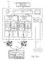
- FIG. 1is a schematic view of an orthogonal frequency division multiplexing (OFDM) system according to an example embodiment, including an OFDM transmitter 22 and an OFDM receiver 24 .
- OFDMorthogonal frequency division multiplexing
- FIG. 2( a ) and FIG. 2( b )are diagrammatic views illustrating time frequency plane arrays respectively depicting two side-by-side repetitions and three side-by-side repetitions of differing pilot patterns.
- FIG. 3( a )is a diagrammatic view illustrating four repetitions of a time frequency plane array having a regularly spaced pilot
- FIG. 3( b )is a diagrammatic view illustrating four repetitions of a time frequency plane arrays resulting from employment of a particular hopping sequence relative to the time frequency plane array of FIG. 3( a ).
- FIG. 4( a )is a diagrammatic view of a time frequency plane array for a Costas array created by a particular permutation sequence
- FIG. 4( b )is a diagrammatic view of a time frequency plane array having two sets of the Costas array of FIG. 4( a ), the two sets being superimposed and time-frequency shifted
- FIG. 4( c )is a diagrammatic view of two sets of the Costas array of FIG. 4( a ), each of the two sets comprising four periods or repetitions and being superimposed and time-frequency shifted.
- FIG. 5( a )is a diagrammatic view of a time frequency plane array having two sets Perfect Periodic Costas arrays, each of the two sets comprising four periods or repetitions and being superimposed and time-frequency shifted;
- FIG. 5( b )is a periodic side lobe distribution array for the Perfect Periodic Costas array of FIG. 5( a ).
- FIG. 6( a )- FIG. 6( d )are diagrammatic views of different cyclic time-frequency shifts of the Costas array of FIG. 4( a ).
- FIG. 7( a ) and FIG. 7( b )are schematic views illustrating an example radio access network which employs a time-frequency shift for expressing a hopped pilot pattern.
- FIG. 8is a schematic view illustrating an example implementation wherein a single node device has plural transmitters/antennas, each utilizing a different time-frequency shift for expressing a hopped pilot pattern.
- FIG. 9is a diagrammatic view of a two-step synchronization design wherein a preamble of a first phase is followed by a data transmission phase.
- FIG. 10( a )is a diagrammatic view of a regularly spaced pilot pattern.
- FIG. 10( b )is a diagrammatic view of a Fourier transform of the pilot pattern of FIG. 10( a ).
- FIG. 11is a diagrammatic view of relative scales of the pilot pattern of FIG. 10( a ) in the time-frequency plane.
- FIG. 1shows an example, non-limiting embodiment of an orthogonal frequency division multiplexing (OFDM) system 20 wherein, for transmissions from a transmitter 22 to a receiver 24 , a single pilot pattern is employed for performing plural, and preferably substantially all, synchronization tasks.
- the multi-purpose pilot patterncan be achieved by hopping the regularly spaced channel estimation pilot in a manner such that (1) the non-aliasing property is preserved while, at the same time, (2) the different acceptable hopping patterns of respective different transmitters can be used for device identification. Since the resulting pilot pattern is a permuted version of the regularly spaced pattern and there is no need for any additional preamble, the pilot overhead for all the synchronization tasks can be kept at minimum.
- the OFDM transmitter 22 of the orthogonal frequency division multiplexing (OFDM) system 20 of FIG. 1receives user data from a user data source 26 .
- OFDM transmitter 22comprises a pre-processing section 28 which can manipulate the user data obtained from user data source 26 by performing such optional functions as serial-to-parallel conversion and channel coding and interleaving.
- the OFDM transmitter 22comprises a combiner 30 which combines the user data (optionally coded and/or interleaved) with non-user data signals such as control signals, synchronization signals, framing signals, and pilot signals.
- non-user data signalssuch as control signals, synchronization signals, framing signals, and pilot signals.
- control signals, synchronization signals, framing signals, and pilot signalsare shown as being applied or received from a non-user data signal source 32 .
- the combiner 30which can be a multiplexer or function as a multiplexer, generates a bit stream by controlled introduction of the non-user data signals into the stream of user data.
- controller 34includes, e.g., a memory, register, or other suitable storage element which contains a hopping sequence 36 uniquely associated with the particular OFDM transmitter 22 , as well as a memory, register, or other suitable means for designating a locally unique time-frequency shift 37 for a time frequency plane array which is configured using the hopping sequence 36 .
- the bit stream output by combiner 30is modulated by modulator 38 onto a series of sub-carriers.
- the modulation performed by modulator 38essentially maps groups of bits to a series of constellation points, represented as complex numbers.
- a parallel-to-serial conversionmay be performed on the complex numbers output by modulator 38 prior to application to an Inverse Fast Fourier Transform (IFFT) unit 40 .
- IFFTInverse Fast Fourier Transform
- the Inverse Fast Fourier Transform (IFFT) unit 40transforms the modulated carriers into a sequence of time domain samples.
- the sequence of time domain samples output by Inverse Fast Fourier Transform (IFFT) unit 40may undergo more processing functions by an optional post-processor 42 .
- post-processing functionscan include one or more of cyclic extension, windowing, peak control, all of which are understood by the person skilled in the art.
- the resultant OFDM waveformis applied to a channel transmission element 44 .
- the channel transmission element 44which can be an antenna or antenna system, for example, applies the OFDM waveform (I, Q output or digital IF signals) to channel 50 .
- the channel 50can be any suitable transmission medium, such as a radio frequency, for example.
- a radio access nodesuch as a base station (also called a Node-B), for example, and a mobile unit (often also termed a mobile station, a mobile terminal, or a user equipment unit (UE), among other appellations).
- UEuser equipment unit
- the wireless receivercan be embodied in or realized as mobile stations such as mobile telephones (“cellular” telephones) and laptops with mobile termination, and thus can be, for example, portable, pocket, hand-held, computer-included, or car-mounted mobile devices which communicate voice and/or data with radio access network.
- the receiverscan be embodiment or implemented in as fixed wireless devices, e.g., fixed cellular devices/terminals which are part of a wireless local loop or the like.
- the OFDM waveformis transmitted over channel 50 , which has its own transmission function (as affected by properties of the channel and factors such as noise and interference, for example).
- the example, non-limiting embodiment of OFDM receiver 24 shown in FIG. 1comprises a channel reception element 60 .
- channel reception element 60can be an antenna or antenna system.
- the OFDM waveform (I, Q input or digital IF signals) as received by channel reception element 60is applied to an optional pre-processing section 62 .
- the pre-processing section 62removes carrier offset caused by transmit and receiver local oscillator differences and selects an appropriate sequence of samples to apply to Fast Fourier Transform (FFT) unit 64 .
- FFTFast Fourier Transform
- the Fast Fourier Transform (FFT) unit 64converts the time domain waveform to the frequency domain, after which an optional serial to parallel conversion may be performed. With the correct timing instant, the individual sub-carriers are demodulated by demodulator 66 .
- the output of demodulator 66is applied to separator 70 .
- the separator 70sorts user data signals from non-user data signals, and may take the form of a demultiplexer or the like. Whatever form it takes, separator 70 is governed by a detector or controller 72 .
- the detector 72is configured to detect non-user data signals such as pilot signals, for example, and to control gating or routing of signals out of separator 70 in accordance with its determination.
- User data signals gated out of separator 70can be applied to an optional post-processing section 74 .
- the post-processing section 74can perform such functions as channel decoding, de-interleaving, and parallel-to-serial conversion, as appropriate.
- the user data thusly obtainedis applied to a user data sink 76 , which can be a voice, text, or other type of application, for example.
- the non-user data signals in the demodulated data streamare detected and used by controller 72 .
- the non-user data signalsare pilot signals.
- the demodulated pilot signalsare particularly applied to both receiver synchronization unit 80 and transmitter identifier 82 .
- the transmitter identifier 82includes transmitter discrimination logic; a memory 84 or other element for storing the hopping sequence; and a library 86 of time-frequency shifts.
- the library 86 of time-frequency shiftscan be embodied in a memory, register, or other storage device, and includes plural time-frequency shift patterns for potential association with corresponding plural OFDM transmitters. As shown in FIG. 1 , the time-frequency shift patterns of library 86 include time-frequency shift patterns 88 1 through 88 j .
- a transmitter of an orthogonal frequency division multiplexing (OFDM) systemsuch as OFDM transmitter 22 transmits data and hopped pilot signals as a distinct (i.e., locally unique) time-frequency shift of a time frequency plane array wherein the pilot signals are hopped using a hopping sequence.
- OFDMorthogonal frequency division multiplexing
- locally uniqueincludes the notion that a receiver capable of receiving OFDM signals from the transmitter would not be capable of or positioned to receive signals from another transmitter having the same time-frequency shift.
- Differing transmitters of the systempreferably transmit using different time-frequency shifts of the time frequency plane array.
- a receiversuch as OFDM receiver 24 identifies a transmitter from which the receiver obtains orthogonal frequency division multiplexing (OFDM) signals by detecting the particular time-frequency shift of the time frequency plane array and associating the particular time-frequency shift with the originating transmitter.
- the controller 72upon detecting the time frequency plane array of its received signals, the controller 72 (which knows the hopping sequence employed to generate the time frequency plane array) can determine how the time frequency plane array has been time-frequency shifted, and upon determining the pattern of the shift can associate the received signals with one of the transmitters for which the receiver 24 has stored time-frequency shift patterns 88 in its library 86 .
- the hopping sequence upon which the time frequency plane array is basedis configured so that any two time-frequency shifts of the time frequency plane array has a predetermined number of coincidences.
- the predetermined number of coincidencescan be zero or a positive integer (e.g., a non-negative integer).
- the predetermined number of coincidencesis one.
- the hopping sequenceis a Costas sequence, and can be a perfect periodic Costas sequence (configured by augmenting a Welsh-constructed periodic Costas array with one of an empty row and an empty column, i.e., an empty row or an empty column). The following provides a preface for, among other things, understanding such configuration or selection of the hopping sequence and the time-frequency shifting of the time frequency plane array.
- FIG. 2( a ) and FIG. 2( b )respectively illustrate two side-by-side repetitions and three side-by-side repetitions of differing pilot patterns as depicted by time frequency plane arrays.
- the OFDM channelis represented as a time-frequency grid, i.e., plane.
- Each column of the gridrepresents the time interval for one OFDM symbol interval, and each OFDM symbol is comprised of a number of tones.
- Each block of the grid which is hatchedrepresents transmission of pilot signals; each non-hatched block of the grid represents transmission of, e.g., user data.
- FIG. 2( b )there are six symbol intervals in each repetition, and sixteen tones in each symbol interval. The tones are numbered along the frequency axis and the symbol intervals, i.e., periods, are numbered along the time axis.
- FIG. 2( a )shows that the pilot signals can be shifted horizontally, e.g., time hopped.
- FIG. 2( b )shows, alternatively, that the pilot signals can be shifted vertically, e.g., frequency hopped. How the pilot signals of FIG. 2( a ) and FIG. 2( b ) are shifted are understood with respect to the positions of the pilot signals in the data transmission phase of FIG. 9 .
- Equation 3provides a mathematical formulation for a base signal c(t) derived from time-hopping a segment of a vertical scan line in the regularly spaced pilot pattern:
- ⁇ lare distinct integers ranging from 0 to L ⁇ 1 and ⁇ is an arbitrary integer.
- the delay hopping pattern ⁇ 0 , ⁇ l , . . . , ⁇ l ⁇ 1 ⁇is one of the L! permutations of the integer set ⁇ 0, 1, . . . , L ⁇ 1 ⁇ .
- a pilot signal designed in accordance with the present technologycan be expressed as shown in Equation 4 as the repetition of the base signal c(t) in both time and frequency:
- the latteris also the pilot insertion period of the regularly spaced pilot given in Table 1.
- the frequency domain period hereis L times that of the regularly spaced pilot due to the length-L time-hopping sequence.
- ⁇ 0 , ⁇ 1 , . . . , ⁇ 5 ⁇⁇ 0,2,1,5,3,4 ⁇ Expression (5)
- the pattern of FIG. 3( b )shows 4 repetitions of the base signal, and is a time-hopped version of the regularly spaced pilot of FIG. 3( a ). From FIG. 3( b ) it is clear that a pilot pattern constructed this way meets the two-dimensional Nyquist criteria since the time hopping as a function of frequency is just horizontal scan line shifts of the regularly spaced pilot pattern.
- the permutation sequence given in Expression (5)is a special sequence called “Costas sequence”.
- the actual frequency separation between two contiguous rowsmay be several sub-carriers as shown in FIG. 3 .
- the actual time separation between two contiguous columnsmay be several OFDM symbols (T s ) if ⁇ is greater than 1.
- a Costas Sequence ⁇ 0 , . . . , ⁇ L ⁇ 1 ⁇has the special property that for any given n ⁇ 0, ⁇ m ⁇ m ⁇ n are distinct for all m within the range. This property ensures that any time-frequency shifted Costas array has at most one coincidence with the original pattern, as shown in FIG. 4( b ).
- the sequence given in Expression (5)belongs to a special category of Costas sequences derived algebraically using the Welch construction W 1 .
- the Welch constructionis described in, e.g., Golomb, Solomon W., and Taylor, Herbert, “Construction and Properties of Costas Arrays”, Proceedings of the IEEE , Vol. 72, No. 9, September 1984, pp. 1143-1163, which is incorporated by reference herein in its entirety.
- the cyclic time-frequency shift of this special category of Costas sequenceshas at most two coincidences with the original pattern, as shown in FIG. 4( c ).
- the Welch construction (W 1 ) category of Costas arrayexists for any integer L if L+1 is a prime.
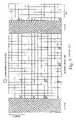
- FIG. 5( a )illustrates use of the Costas sequence for time-hopping the elements in a vertical scan, and accordingly shows addition of an empty column for formation of a Perfect Periodic Costas Array.
- FIG. 5( b )shows a corresponding periodic side lobe array where the number in the n th row of the m th column corresponds to the number of coincidences per period between the original pattern and its cyclic shifted version with m units of offset in time and n units of offset in frequency.
- Such type of extensionwill be referred to as a Perfect Periodic Costas Array since there can be no further side lobe reduction. It should be understood that in the example of FIG. 5( a ) and FIG. 5( b ) an empty column is added to form the Perfect Periodic Costas Array since the Costas sequence is used for time-hopping the elements in a vertical scan. In other examples in which the Costas sequence is used for frequency-hopping the elements in a horizontal scan, an empty row is added to form the appropriate Perfect Periodic Costas Array.
- the controller 72can then search its library 86 for the shift pattern and, by associating the shift pattern with a transmitter, determine the transmitter from which the OFDM receiver 24 is receiving the OFDM signals.
- the frequency shiftdoes not have to be a multiple of f p in Equation 3. Since f p is shown as a multiple by the notation M of the sub-carrier spacing f s , the shift can (but does not have to) be a multiple of f s . When two patterns have a relative frequency shift that is not a multiple of f p , they have no coincidence at all. Hence, the predetermined number of coincidences can be zero or a positive integer (i.e., a non-negative integer).
- the hopping sequencecan be periodic. For example, if there are more pilots in a scan line than the length of the Costas sequence, the hopping can be repeated as illustrated, e.g., in FIG. 4( c ) where there are four periods of the basic Costas array (two periods in the time domain and two periods in the frequency domain). In the time domain, the hopping pilot pattern can repeat indefinitely. In the frequency domain, on the other hand, the number of repetitions will be limited by the bandwidth. If necessary, the last repetition may need to wrap around. Viewed, e.g., in this manner, the time-frequency shift of the hopping sequence can be viewed as a cyclic or circular shift, as hereinbefore expressed.
- each of plural communicating devices of a telecommunications systemcan be identified by a permutation of a time-frequency pattern of signals transmitted from the device.
- the permutation of the time-frequency patternresults either in the time-frequency pattern itself (a null permutation) or a cyclic shifting of the time-frequency pattern.
- the time-frequency patternpreferably includes hopped pilot signals which are hopped either in a frequency domain or a time domain.
- the hopped pilot signalsare hopped in accordance with a Costas sequence, which Costas sequence can be repeated for one or more periods to accommodate a number of pilot signals in one of the time domain and the frequency domain.
- the hopped pilot signalscan be hopped in accordance with a perfect periodic Costas sequence configured by augmenting a Welsh-constructed periodic Costas array with an empty row or an empty column.
- the device identified by the permutation of a time-frequency patterncan be a radio access network node or a wireless mobile station, for example.
- the disclosed pilot patterncan be used in either reservation or non-reservation approaches.
- the reservation modereserves a subset of the sub-carriers (every M th sub-carrier, for example) exclusively for the pilot.
- the non-reservation modeallows data to be transmitted in sub-carriers that are used by other devices as pilots. To maintain the same performance in the non-reservation mode, however, the pilot has to be transmitted at higher power than the data. It is also possible to use more than one subset of sub-carriers for pilot if required. For example, the first subset includes every M th sub-carriers while the second one includes every M th plus 1 sub-carriers. In this case, the two sets are completely orthogonal to each other and free of interference.
- the pilot patternis transmitted in a time-frequency plane array that also includes user data (e.g., non-pilot data).
- user datae.g., non-pilot data
- the time-frequency plane arraymay contain essentially only the hopped pilot pattern and thereby serve more limited purposes (such as providing device identification without having to be accompanied by, e.g., user data).
- the pilot patterns described herein which facilitate device identification by permutation of a time-frequency pattern of signals transmitted from the deviceis not limited to applications or implementations involving orthogonal frequency division multiplexing (OFDM). Rather, principles of the signal set as described herein are suitable for any communication system to achieve synchronization and device identification, and is not confined to any specific data transmission technique such as OFDM, CDMA or TDMA. The signal can actually be used as preamble in all these techniques if not repeated continuously and if not mingled with data transmission.
- OFDMorthogonal frequency division multiplexing
- FIG. 7( a )illustrates one example environment of use for the pilot pattern technology described herein, e.g., a wireless cellular telecommunications network 100 having a radio access network (RAN) 102 .
- the RAN 102is typically connected to core or external network(s) 104 .
- the RAN 102may include one or more base station controllers or radio network controllers (RNCs) 106 and one or more base stations (BS) 108 .
- RNCsradio network controllers
- BSbase stations
- the RAN 102 of FIG. 7( a )is shown with only two RNC nodes, particularly RNC 106 1 and RNC 106 2 .
- Each RNC 106is connected to one or more base stations (BS) 108 .
- RNC 106 1serves base station 108 1-1 and base station 108 1-2
- RNC 106 2serves base station 108 2-1 and base station 108 2-2
- FIG. 7( a )shows that an RNC can be connected to one or more other RNCs in the RAN 102 .
- a base stationis sometimes also referred to in the art as a radio base station, a node B, or B-node.
- each base station 108is shown as serving one cell.
- Each cellis represented by a circle which surrounds the respective base station. It will be appreciated by those skilled in the art, however, that a base station may serve for communicating across the air interface for more than one cell. For example, two cells may utilize resources situated at the same base station site. Moreover, each cell may be divided into one or more sectors, with each sector having one or more cell/carriers.
- a mobile station (MS)such as user equipment unit (UE) 110 shown in FIG. 7( a ), communicates with one or more cells or one or more base stations (BS) 108 over a radio or air interface 112 .
- FIG. 7( a )shows that the base stations 108 may each comprise a transmitter 122 similar to that of transmitter 22 of the example embodiment of FIG. 1 , and a receiver 124 .
- Transmitter 122 of each base station 108includes logic and/or information for generating its locally unique time-frequency shift 137 .
- base station 108 1-2includes logic and/or information for generating its locally unique time-frequency shift 137 1-2 .
- the signals transmitted from antenna 144 1-2 of base station 108 1-2include a hopping pilot sequence reflected by pattern 150 1-2 shown in FIG. 7( a ) for uniquely identifying base station 108 1-1 .
- the hopping pilot sequence reflected by pattern 150 1-1happens to be the same pattern as depicted in FIG. 6( b ).
- base station 108 1-2includes logic and/or information for generating its locally unique time-frequency shift 137 1-2 .
- the signals transmitted from antenna 144 1-2 of base station 108 1-2include a hopping pilot sequence reflected by pattern 150 1-2 for uniquely identifying base station 108 1-2 .
- the hopping pilot sequence reflected by pattern 150 1-2happens to be the same pattern as depicted in FIG. 6( c ).
- FIG. 7( a )further shows that the receivers 124 of the base stations 108 may each comprise antenna.
- receiver 124 1-1 of base station 108 1-1comprises antenna 160 1-1
- receiver 124 1-2 of base station 108 1-2comprises antenna 160 1-2 .
- the mobile station 120typically includes a transmitter 122 MS and a receiver 124 MS .
- the receiver 124 MSincludes a transmitter identifier 182 MS which functions essentially in the same manner as the transmitter identifier 82 MS of FIG. 1 for determining from which transmitter (e.g., whether from base station 108 1-1 or 108 1-2 received signal originates.
- the transmitter identifier 182 MSwhich makes the determination based on the time-frequency shift of the received signal. For example, when receiving a signal having a hopping pilot of the pattern 150 1-1 , the transmitter identifier 182 MS realizes that the signal is received from base station 108 1-1 . On the other than, when receiving a signal having a hopping pilot of the pattern 150 1-2 , the transmitter identifier 182 MS realizes that the signal is received from base station 108 1-2 .
- FIG. 7( b )illustrates that the time-frequency shift of the hopping pilot pattern can optionally be utilized in two-way communication between a base station 108 and the mobile station 110 .
- the transmitter 122 MS of mobile station 110is provided with a processor or other element which implements a signatory time-frequency shift of the hopping pilot pattern.
- transmitter 122 MS of the mobile station 110 of FIG. 7( b )is provided with logic and/or information for generating its locally unique time-frequency shift 137 MS .
- each base station 108can be provided with a transmitter identifier 182 .
- each base station 108can determine the particular mobile station from which it receives signals base on the signatory time-frequency shift of its signals as imposed by the originating mobile station.
- FIG. 8illustrates another example implementation of the pilot pattern technology wherein a transmitting node (TN) 200 has multiple transmitters 222 and/or multiple antennas 244 .
- the transmitting node 200has antenna 244 TN-1 and antenna 244 TN-2 .
- the pilot signals applied to antenna 244 TN-1 and broadcast by transmitting node 200 from antenna 244 TN-1are configured in accordance with first time-frequency shift, while the pilot signals applied to antenna 244 TN-2 and broadcast by transmitting node 200 from antenna 244 TN-2 are configured in accordance with second time-frequency shift.
- the pilot signals applied to antenna 244 TN-1 and broadcast by transmitting node 200 from antenna 244 TN-1happen to be of the same pattern as depicted in FIG. 6( b ).
- the pilot signals applied to antenna 244 TN-2 and broadcast by transmitting node 200 from antenna 244 TN-2happen to be of the same pattern as depicted in FIG. 6( c ).
- the implementation of FIG. 8can be a Multiple Input Multiple Output (MIMO) antenna system, in which multiple antennas of the transmitting node need to be individually identified.
- MIMOMultiple Input Multiple Output
- a receiversuch as receiver 224 RN in receiving node (RN) 210 can distinguish between the plural antennas (e.g., antennas 244 TN-1 , 244 TN-2 ) of the same transmitting node by discerning the characteristic time-frequency shift of the received signals and associating the characteristic time-frequency shift with a particular antenna.
- the transmitting node of FIG. 8can be a fixed network node such as a radio base station or a radio access network (in which case the receiver node , the transmitting node can be a mobile station).
- the transmitting nodecan be a mobile node.
- the nodes described in FIG. 8need not be dedicated to transmission or reception, as the transmitting node can also have a receiver for two-way communication (and likewise the receiving node can have a transmitter for two-way communication).
- reference numerals 237 TN-1 , 237 TN-2 , 260 TN-1 , 260 TN-2 , 250 1 , 250 2 , 222 RN , and 282 RN of FIG. 8refer to comparable elements as elements 137 TN-1 , 137 TN-2 , 160 TN-1 , 160 TN-2 , 150 1 , 150 2 , 122 RN , and 182 RN of FIG. 7( a ), for example.
- the Costas Arrayhas the additional advantage of better delay-Doppler resolution.
- the time-hopping patternhas L times better Doppler resolution for a single period of observation in time than a regularly spaced pattern. This allows the initial synchronization to be established very quickly.
- the disclosed pilot patterncan extend in time and frequency easily by repetitions. It can even skip a certain time-frequency region that may have been occupied by other systems.
Landscapes
- Engineering & Computer Science (AREA)
- Signal Processing (AREA)
- Computer Networks & Wireless Communication (AREA)
- Mobile Radio Communication Systems (AREA)
- Electric Clocks (AREA)
Abstract
Description
λ(n,m)p(t−nTs)ej2πmf
In
h(τ,ν)Δ∫∫H(t,f)ej2πτfe−j2πvtdtdf. Equation (2)
| TABLE 1 |
| Summary of Notations |
| Parameter | Comment | Value (example) | |
| maximal delay spread | 7.8125 μsec | ||
| maximal Doppler spread | 500 Hz | ||
| Tp | pilot insertion period in | 2 msec | |
| (1/ | |||
| fp | pilot insertion period in freq. domain | 128 kHz | |
| (1/ | |||
| pilot density | 1/256 | ||
| Ts= Tp/N | 2/16 msec | ||
| fs= fp/M | 128/16 kHz | ||
In
In Equation 4, Fp=Lfp=LMfsand Tp=NTsare the frequency and time domain periods of this repetition respectively. The latter is also the pilot insertion period of the regularly spaced pilot given in Table 1. However, the frequency domain period here is L times that of the regularly spaced pilot due to the length-L time-hopping sequence.
{τ0, τ1, . . . , τ5}={0,2,1,5,3,4} Expression (5)
The pattern of
Claims (41)
Priority Applications (5)
| Application Number | Priority Date | Filing Date | Title |
|---|---|---|---|
| US11/292,415US7711029B2 (en) | 2005-12-02 | 2005-12-02 | Hopping pilot pattern for telecommunications |
| EP06813075.6AEP1955508A4 (en) | 2005-12-02 | 2006-11-17 | Hopping pilot pattern for telecommunications |
| EP14178211.0AEP2824864A1 (en) | 2005-12-02 | 2006-11-17 | Hopping pilot pattern for telecommunications |
| PCT/SE2006/050455WO2007064286A2 (en) | 2005-12-02 | 2006-11-17 | Hopping pilot pattern for telecommunications |
| TW095143980ATWI365622B (en) | 2005-12-02 | 2006-11-28 | Transmitter, receiver, telecommunications system, receiving node of a telecommunications system and method of operating a telecommuncations system |
Applications Claiming Priority (1)
| Application Number | Priority Date | Filing Date | Title |
|---|---|---|---|
| US11/292,415US7711029B2 (en) | 2005-12-02 | 2005-12-02 | Hopping pilot pattern for telecommunications |
Publications (2)
| Publication Number | Publication Date |
|---|---|
| US20070133462A1 US20070133462A1 (en) | 2007-06-14 |
| US7711029B2true US7711029B2 (en) | 2010-05-04 |
Family
ID=38092671
Family Applications (1)
| Application Number | Title | Priority Date | Filing Date |
|---|---|---|---|
| US11/292,415Active2028-11-25US7711029B2 (en) | 2005-12-02 | 2005-12-02 | Hopping pilot pattern for telecommunications |
Country Status (4)
| Country | Link |
|---|---|
| US (1) | US7711029B2 (en) |
| EP (2) | EP2824864A1 (en) |
| TW (1) | TWI365622B (en) |
| WO (1) | WO2007064286A2 (en) |
Cited By (13)
| Publication number | Priority date | Publication date | Assignee | Title |
|---|---|---|---|---|
| US20090268829A1 (en)* | 2008-04-29 | 2009-10-29 | Hong Kong Applied Science And Technology Research Institute Co., Ltd. | Systems and Methods for Sampling Frequency Offset Estimation |
| US20090285173A1 (en)* | 2008-04-10 | 2009-11-19 | Telefonaktielbolaget Lm Ericsson (Publ) | Pilot design using costas arrays |
| US20100027479A1 (en)* | 2008-07-31 | 2010-02-04 | Qualcomm Incorporated | Tone selection in communication networks |
| US20100146141A1 (en)* | 2007-05-31 | 2010-06-10 | Electronics And Telecommunications Research Institute | Transmission method, transmission apparatus, reception method, reception apparatus of digital broadcasting signal |
| US20100238787A1 (en)* | 2006-09-11 | 2010-09-23 | Jiann-Ching Guey | Detection of time-frequency hopping patterns |
| US20110159882A1 (en)* | 2009-12-29 | 2011-06-30 | Industrial Technology Research Institute | Pilot selection method, wireless communication system and base station thereof |
| WO2014188414A1 (en)* | 2013-05-23 | 2014-11-27 | Elta Systems Ltd. | Receiver, system and method for frequency diversity communications using beacon and methods useful in conjunction therewith |
| WO2016064315A1 (en)* | 2014-10-24 | 2016-04-28 | Telefonaktiebolaget L M Ericsson (Publ) | Hopping pattern for synchronization signals |
| USRE46437E1 (en)* | 2007-04-06 | 2017-06-13 | Lg Electronics Inc. | DTV transmitting system and method of processing DTV signal |
| US9847810B2 (en) | 2013-05-23 | 2017-12-19 | Elta Systems Ltd. | Add-on apparatus for channel compensation of frequency diversity communications and methods useful in conjunction therewith |
| US9960832B2 (en) | 2013-05-23 | 2018-05-01 | Elta Systems Ltd. | Add-on apparatus for synchronization of frequency diversity communications and methods useful in conjunction therewith |
| US10128935B2 (en) | 2012-11-01 | 2018-11-13 | Elta Systems Ltd. | Partial downlink repeater apparatus and methods useful in conjunction therewith |
| US10389558B2 (en)* | 2016-10-03 | 2019-08-20 | Mediatek Inc. | Method and apparatus for synchronization |
Families Citing this family (49)
| Publication number | Priority date | Publication date | Assignee | Title |
|---|---|---|---|---|
| US8588171B2 (en)* | 2006-09-25 | 2013-11-19 | Panasonic Corporation | Radio communication device and pilot arrangement method |
| DE102006047978A1 (en)* | 2006-10-10 | 2008-04-17 | Siemens Ag | A method of operating a radio communication system using OFDM, as well as radio communication system, transmitting station and receiving station |
| US8300674B2 (en) | 2007-01-12 | 2012-10-30 | Telefonaktiebolaget L M Ericsson (Publ) | Method and apparatus for complexity reduction in detection of delay and Doppler shifted signature sequences |
| US8213483B2 (en)* | 2007-02-06 | 2012-07-03 | Qualcomm Incorporated | Hopping structures for broadband pilot signals |
| US7720164B2 (en)* | 2007-02-26 | 2010-05-18 | Telefonaktiebolaget L M Ericsson (Publ) | Transmission scheme for uplink access in a FDMA system |
| US8526524B2 (en)* | 2007-03-27 | 2013-09-03 | Qualcomm Incorporation | Orthogonal reference signal permutation |
| CN101330487B (en)* | 2007-06-19 | 2012-04-04 | 华为技术有限公司 | A symbol interleaving method, device and terminal equipment |
| JP4606448B2 (en)* | 2007-10-01 | 2011-01-05 | 株式会社エヌ・ティ・ティ・ドコモ | User apparatus, transmission method, and communication system |
| US20090168730A1 (en)* | 2007-10-29 | 2009-07-02 | Motorola, Inc. | Pilot Signal Allocation Method and Apparatus |
| US20110026482A1 (en)* | 2008-03-27 | 2011-02-03 | Postdata Co., Ltd. | Method and apparatus for pilot signal transmission |
| US8681833B2 (en)* | 2008-04-23 | 2014-03-25 | Sharp Kabushiki Kaisha | Communication system, transmitter, receiver and communication method |
| CN101621325A (en)* | 2008-07-03 | 2010-01-06 | 中兴通讯股份有限公司 | Common pilot frequency hopping method in LTE system |
| CN101741420B (en) | 2008-11-12 | 2013-08-07 | 华为技术有限公司 | Channel estimation methods, device and system |
| US7940740B2 (en)* | 2009-02-03 | 2011-05-10 | Motorola Mobility, Inc. | Apparatus and method for communicating and processing a positioning reference signal based on identifier associated with a base station |
| US8730925B2 (en) | 2009-04-09 | 2014-05-20 | Motorola Mobility Llc | Method and apparatus for generating reference signals for accurate time-difference of arrival estimation |
| US20100278047A1 (en)* | 2009-05-04 | 2010-11-04 | Havish Koorapaty | System and Method for Parameter Estimation with Interference Suppression in a Telecommunications Network |
| US9002354B2 (en) | 2009-06-12 | 2015-04-07 | Google Technology Holdings, LLC | Interference control, SINR optimization and signaling enhancements to improve the performance of OTDOA measurements |
| US8467346B2 (en)* | 2009-06-19 | 2013-06-18 | Futurewei Technologies, Inc. | Method and apparatus for generating time-frequency patterns for reference signal in an OFDM wireless communication system |
| US8483707B2 (en)* | 2009-06-26 | 2013-07-09 | Motorola Mobility Llc | Wireless terminal and method for managing the receipt of position reference singals for use in determining a location |
| US20110039583A1 (en)* | 2009-08-17 | 2011-02-17 | Motorola, Inc. | Muting time masks to suppress serving cell interference for observed time difference of arrival location |
| US8374633B2 (en) | 2009-10-05 | 2013-02-12 | Motorola Mobility Llc | Muting indication to enable improved time difference of arrival measurements |
| US20110176440A1 (en)* | 2010-01-15 | 2011-07-21 | Motorola-Mobility, Inc. | Restrictions on autonomous muting to enable time difference of arrival measurements |
| US8509102B2 (en)* | 2010-02-24 | 2013-08-13 | Motorola Mobility Llc | Threshold determination in TDOA-based positioning system |
| US9203489B2 (en) | 2010-05-05 | 2015-12-01 | Google Technology Holdings LLC | Method and precoder information feedback in multi-antenna wireless communication systems |
| US8428022B2 (en) | 2010-08-27 | 2013-04-23 | Motorola Mobility Llc | Method and apparatus for transmitting positioning reference signals in a wireless communication network |
| US10003998B2 (en)* | 2012-05-04 | 2018-06-19 | Qualcomm Incorporated | Systems and methods for reduced overhead in wireless communication systems |
| US9813262B2 (en) | 2012-12-03 | 2017-11-07 | Google Technology Holdings LLC | Method and apparatus for selectively transmitting data using spatial diversity |
| US9591508B2 (en) | 2012-12-20 | 2017-03-07 | Google Technology Holdings LLC | Methods and apparatus for transmitting data between different peer-to-peer communication groups |
| US9979531B2 (en) | 2013-01-03 | 2018-05-22 | Google Technology Holdings LLC | Method and apparatus for tuning a communication device for multi band operation |
| US10229697B2 (en) | 2013-03-12 | 2019-03-12 | Google Technology Holdings LLC | Apparatus and method for beamforming to obtain voice and noise signals |
| EP3025467B1 (en)* | 2013-07-26 | 2017-08-23 | Empire Technology Development LLC | Pilot frequency sequence determination |
| US9077444B2 (en) | 2013-09-12 | 2015-07-07 | Motorola Solutions, Inc. | Method and apparatus for late entry in asynchronous frequency hopping systems using random permutation sequences |
| US9386542B2 (en) | 2013-09-19 | 2016-07-05 | Google Technology Holdings, LLC | Method and apparatus for estimating transmit power of a wireless device |
| US9549290B2 (en) | 2013-12-19 | 2017-01-17 | Google Technology Holdings LLC | Method and apparatus for determining direction information for a wireless device |
| US9491007B2 (en) | 2014-04-28 | 2016-11-08 | Google Technology Holdings LLC | Apparatus and method for antenna matching |
| US9478847B2 (en) | 2014-06-02 | 2016-10-25 | Google Technology Holdings LLC | Antenna system and method of assembly for a wearable electronic device |
| US20150365982A1 (en)* | 2014-06-13 | 2015-12-17 | Sony Corporation | Massive mimo link setup |
| US11005628B2 (en)* | 2015-08-04 | 2021-05-11 | Futurewei Technologies, Inc. | Device, network, and method for wideband LTE single OFDM symbol uplink transmission |
| EP3348015B1 (en) | 2015-09-07 | 2022-09-07 | Cohere Technologies, Inc. | Multiple access using orthogonal time frequency space modulation |
| US10574425B2 (en)* | 2016-06-28 | 2020-02-25 | Lg Electronics Inc. | Method for receiving downlink signal and user equipment, and method for transmitting downlink signal and base station |
| WO2018064895A1 (en)* | 2016-10-03 | 2018-04-12 | Mediatek Inc. | Method and apparatus for synchronization |
| DE102016220882A1 (en)* | 2016-10-24 | 2018-04-26 | Fraunhofer-Gesellschaft zur Förderung der angewandten Forschung e.V. | Optimized hopping patterns for different sensor nodes and variable data lengths based on the telegram splitting transmission method |
| DE102016220883A1 (en) | 2016-10-24 | 2018-04-26 | Fraunhofer-Gesellschaft zur Förderung der angewandten Forschung e.V. | Optimized combination of preamble and data fields for sensor networks with low power consumption based on the telegram splitting method |
| CN107395251B (en)* | 2017-07-17 | 2019-07-02 | 电子科技大学 | A Frequency Hopping Sequence Generation Method for Multi-Transceiver Cognitive Wireless Networks |
| CN111510183B (en)* | 2020-03-25 | 2021-05-11 | 北京理工大学 | A coherent fast frequency hopping multi-channel parallel local oscillator phase calculation method and local oscillator structure |
| US12276751B2 (en)* | 2020-09-29 | 2025-04-15 | Qualcomm Incorporated | Waveform reporting for cooperative sensing |
| CN112564843B (en)* | 2020-11-19 | 2024-07-05 | 无锡泽太微电子有限公司 | Micro-frequency hopping method and micro-frequency hopping multiple access communication system |
| CN113179237B (en)* | 2021-02-05 | 2024-02-23 | 西安宇飞电子技术有限公司 | Synchronous broadcasting device with frequency jitter |
| CN115567163A (en)* | 2022-09-29 | 2023-01-03 | 安徽乾栋智能科技有限公司 | A method, system and device for blind detection of frequency hopping signals |
Citations (25)
| Publication number | Priority date | Publication date | Assignee | Title |
|---|---|---|---|---|
| US6047171A (en) | 1998-01-08 | 2000-04-04 | Ericsson Inc. | Method and apparatus for combating adjacent channel interference using multiple IF filters |
| US6320843B1 (en) | 1998-11-18 | 2001-11-20 | Ericsson Inc. | Wireless communications systems with standard and robust services and methods of operation thereof |
| US6332006B1 (en) | 1998-11-18 | 2001-12-18 | Ericsson Inc. | Apparatus and methods for providing high-penetration messaging in wireless communications systems |
| US20020106008A1 (en) | 2000-11-29 | 2002-08-08 | Jiann-Ching Guey | Receiver architecture for transmit diversity in CDMA system |
| US6480556B1 (en) | 1999-04-27 | 2002-11-12 | Ericsson Inc. | Rate detection apparatus and method for variable rate speech encoding |
| US6594793B1 (en) | 2000-09-08 | 2003-07-15 | Ericsson Inc. | Methods and systems for multiplexing and decoding variable length messages in digital communications systems |
| US6671309B1 (en)* | 1999-09-28 | 2003-12-30 | Telefonaktiebolaget Lm Ericsson (Publ) | Interference diversity in communications networks |
| US20040071110A1 (en) | 2002-10-09 | 2004-04-15 | Jiann-Ching Guey | Methods, systems, and computer program products for allocating bandwidth in a radio packet data system based on data rate estimates determined for one or more idle transmitter/sector scenarios |
| US20040095902A1 (en) | 2002-08-26 | 2004-05-20 | Rajiv Laroia | Beacon signaling in a wireless system |
| US20040257979A1 (en) | 2003-06-18 | 2004-12-23 | Samsung Electronics Co., Ltd. | Apparatus and method for tranmitting and receiving a pilot pattern for identification of a base station in an OFDM communication system |
| US6876645B1 (en) | 2000-07-05 | 2005-04-05 | Ericsson Inc. | Delay and channel estimation for multi-carrier CDMA system |
| US20050147024A1 (en)* | 2003-10-29 | 2005-07-07 | Samsung Electronics Co., Ltd | Communication method in an FH-OFDM cellular system |
| US6954481B1 (en)* | 2000-04-18 | 2005-10-11 | Flarion Technologies, Inc. | Pilot use in orthogonal frequency division multiplexing based spread spectrum multiple access systems |
| US20050226141A1 (en) | 2004-04-09 | 2005-10-13 | Samsung Electronics Co., Ltd. | Apparatus and method for transmitting/receiving pilot code pattern for identification of base station in communication system using orthogonal frequency division multiplexing scheme |
| US6959032B1 (en) | 2000-06-12 | 2005-10-25 | Time Domain Corporation | Method and apparatus for positioning pulses in time |
| US20050238083A1 (en)* | 2000-04-18 | 2005-10-27 | Rajiv Laroia | Base station identification in orthongonal frequency division multiplexing based spread spectrum multiple access systems |
| US20050249181A1 (en) | 2004-05-04 | 2005-11-10 | Rajiv Vijayan | Staggered pilot transmission for channel estimation and time tracking |
| US6990153B1 (en)* | 2001-02-06 | 2006-01-24 | Agency For Science, Technology And Research | Method and apparatus for semi-blind communication channel estimation |
| US20060045001A1 (en)* | 2004-08-25 | 2006-03-02 | Ahmad Jalali | Transmission of signaling in an OFDM-based system |
| US20070036179A1 (en)* | 2005-08-09 | 2007-02-15 | Ravi Palanki | Channel and interference estimation in single-carrier and multi-carrier frequency division multiple access systems |
| US20070053282A1 (en)* | 2001-10-17 | 2007-03-08 | Wen Tong | Scattered pilot pattern and channel estimation method for MIMO-OFDM systems |
| US7292651B2 (en)* | 1998-12-31 | 2007-11-06 | At&T Corp. | Pilot-aided channel estimation for OFDM in wireless systems |
| US7369531B2 (en)* | 2003-10-31 | 2008-05-06 | Samsung Eectronics Co., Ltd | Apparatus and method for transmitting/receiving a pilot signal for distinguishing a base station in a communication system using an OFDM scheme |
| US7433419B2 (en)* | 2003-10-27 | 2008-10-07 | Samsung Electronics Co., Ltd. | ICI cancellation method for an OFDM system |
| US20080310484A1 (en)* | 2000-07-19 | 2008-12-18 | Lot 41 Acquisition Foundation, Llc | Software Adaptable High Performance Multicarrier Transmission Protocol |
Family Cites Families (1)
| Publication number | Priority date | Publication date | Assignee | Title |
|---|---|---|---|---|
| WO2005081437A1 (en)* | 2004-02-17 | 2005-09-01 | Huawei Technologies Co., Ltd. | Multiplexing scheme in a communication system |
- 2005
- 2005-12-02USUS11/292,415patent/US7711029B2/enactiveActive
- 2006
- 2006-11-17EPEP14178211.0Apatent/EP2824864A1/ennot_activeWithdrawn
- 2006-11-17WOPCT/SE2006/050455patent/WO2007064286A2/enactiveApplication Filing
- 2006-11-17EPEP06813075.6Apatent/EP1955508A4/ennot_activeWithdrawn
- 2006-11-28TWTW095143980Apatent/TWI365622B/enactive
Patent Citations (28)
| Publication number | Priority date | Publication date | Assignee | Title |
|---|---|---|---|---|
| US6047171A (en) | 1998-01-08 | 2000-04-04 | Ericsson Inc. | Method and apparatus for combating adjacent channel interference using multiple IF filters |
| US6320843B1 (en) | 1998-11-18 | 2001-11-20 | Ericsson Inc. | Wireless communications systems with standard and robust services and methods of operation thereof |
| US6332006B1 (en) | 1998-11-18 | 2001-12-18 | Ericsson Inc. | Apparatus and methods for providing high-penetration messaging in wireless communications systems |
| US7292651B2 (en)* | 1998-12-31 | 2007-11-06 | At&T Corp. | Pilot-aided channel estimation for OFDM in wireless systems |
| US6480556B1 (en) | 1999-04-27 | 2002-11-12 | Ericsson Inc. | Rate detection apparatus and method for variable rate speech encoding |
| US6671309B1 (en)* | 1999-09-28 | 2003-12-30 | Telefonaktiebolaget Lm Ericsson (Publ) | Interference diversity in communications networks |
| US6961364B1 (en) | 2000-04-18 | 2005-11-01 | Flarion Technologies, Inc. | Base station identification in orthogonal frequency division multiplexing based spread spectrum multiple access systems |
| US20050238083A1 (en)* | 2000-04-18 | 2005-10-27 | Rajiv Laroia | Base station identification in orthongonal frequency division multiplexing based spread spectrum multiple access systems |
| US6954481B1 (en)* | 2000-04-18 | 2005-10-11 | Flarion Technologies, Inc. | Pilot use in orthogonal frequency division multiplexing based spread spectrum multiple access systems |
| US6959032B1 (en) | 2000-06-12 | 2005-10-25 | Time Domain Corporation | Method and apparatus for positioning pulses in time |
| US6876645B1 (en) | 2000-07-05 | 2005-04-05 | Ericsson Inc. | Delay and channel estimation for multi-carrier CDMA system |
| US20080310484A1 (en)* | 2000-07-19 | 2008-12-18 | Lot 41 Acquisition Foundation, Llc | Software Adaptable High Performance Multicarrier Transmission Protocol |
| US6594793B1 (en) | 2000-09-08 | 2003-07-15 | Ericsson Inc. | Methods and systems for multiplexing and decoding variable length messages in digital communications systems |
| US6754253B2 (en) | 2000-11-29 | 2004-06-22 | Ericsson Inc. | Receiver architecture for transmit diversity in CDMA system |
| US20020106008A1 (en) | 2000-11-29 | 2002-08-08 | Jiann-Ching Guey | Receiver architecture for transmit diversity in CDMA system |
| US6990153B1 (en)* | 2001-02-06 | 2006-01-24 | Agency For Science, Technology And Research | Method and apparatus for semi-blind communication channel estimation |
| US20070053282A1 (en)* | 2001-10-17 | 2007-03-08 | Wen Tong | Scattered pilot pattern and channel estimation method for MIMO-OFDM systems |
| US7248559B2 (en)* | 2001-10-17 | 2007-07-24 | Nortel Networks Limited | Scattered pilot pattern and channel estimation method for MIMO-OFDM systems |
| US20040095902A1 (en) | 2002-08-26 | 2004-05-20 | Rajiv Laroia | Beacon signaling in a wireless system |
| US20040071110A1 (en) | 2002-10-09 | 2004-04-15 | Jiann-Ching Guey | Methods, systems, and computer program products for allocating bandwidth in a radio packet data system based on data rate estimates determined for one or more idle transmitter/sector scenarios |
| US20040257979A1 (en) | 2003-06-18 | 2004-12-23 | Samsung Electronics Co., Ltd. | Apparatus and method for tranmitting and receiving a pilot pattern for identification of a base station in an OFDM communication system |
| US7433419B2 (en)* | 2003-10-27 | 2008-10-07 | Samsung Electronics Co., Ltd. | ICI cancellation method for an OFDM system |
| US20050147024A1 (en)* | 2003-10-29 | 2005-07-07 | Samsung Electronics Co., Ltd | Communication method in an FH-OFDM cellular system |
| US7369531B2 (en)* | 2003-10-31 | 2008-05-06 | Samsung Eectronics Co., Ltd | Apparatus and method for transmitting/receiving a pilot signal for distinguishing a base station in a communication system using an OFDM scheme |
| US20050226141A1 (en) | 2004-04-09 | 2005-10-13 | Samsung Electronics Co., Ltd. | Apparatus and method for transmitting/receiving pilot code pattern for identification of base station in communication system using orthogonal frequency division multiplexing scheme |
| US20050249181A1 (en) | 2004-05-04 | 2005-11-10 | Rajiv Vijayan | Staggered pilot transmission for channel estimation and time tracking |
| US20060045001A1 (en)* | 2004-08-25 | 2006-03-02 | Ahmad Jalali | Transmission of signaling in an OFDM-based system |
| US20070036179A1 (en)* | 2005-08-09 | 2007-02-15 | Ravi Palanki | Channel and interference estimation in single-carrier and multi-carrier frequency division multiple access systems |
Non-Patent Citations (15)
| Title |
|---|
| Benedetto et al, "International Conference on Concatenating Codes for Improved Ambiguity Behavior", Electromagnetics in Advanced Applications, 2007, pp. 464-467. |
| Chang et al, "Frequency Coded Waveforms for Enhanced Delay-Doppler Resolution", IEEE Transactions on Information Theory, vol. 49, No. 11, 2003, pp. 2960-2971. |
| Chang et al, "Transmitter Architecture for Pulsed OFDM" Proceedings, IEEE Asia Pacific Conference on Circuits and Systems, pp. 693-696, 2004. |
| Costas, "A Study of a Class of Detection Waveforms Having Nearly Ideal Range-Doppler Ambiguity Properties", Proceedings of the IEEE, vol. 72, No. 8, Aug. 1964, pp. 996-1009. |
| Golomb et al, "Constructions and Properties of Costas Arrays", Proceedings of the IEEE, vol. 72, No. 9, Sep. 1964, pp. 1143-1163. |
| Guey et al, "Synchronization Signal Design for OFDM Based on Time-Frequency Hopping Patterns", Conference on Communications, IEEE Communications Society, 2007, pp. 4329-4334. |
| Ham et al, "Inverse Filtering in the Presence of Doppler with Application to Specular Multipath Parameter Estimation", 1995 International Conference on Acoustics, Speech, and Signal Processing, 1995, vol. 5, pp. 3167-3170. |
| International Search Report and Written Opinion mailed Jul. 8, 2008 in PCT application PCT/SE2007/051027. |
| International Search Report and Written Opinion mailed May 16, 2007 in corresponding PCT appln. PCT/SE2006/050455. |
| Janjua et al, "Implementation of OFDM Transmitter Based on the IEEE 802.16d Standard", Dec. 2, 2004. |
| Klein et al, "Multiple Access OFDM for High Bit Rate Indoor Wireless Systems", Dept. of EECS, University of California Berkeley, Jun. 1999. |
| McNair et al, "OFDM for High Data Rate, High-Mobility, Wide-Area Wireless Communications", Proc. IEEE Sarnoff Symposium, Princeton, NJ, Mar. 2001. |
| Popovic et al, "User Traffic Multiplexing on OFDM Downlink", Spread Spectrum Techniques and Applications, 2004, IEEE Eighth Int'l. Symposium, Aug. 30-Sep. 2, 2004, pp. 429-433. |
| Tech. Spec. 3GPP TR 25.892, V2.0.0, 3rd Generation Partnership Project; Technical Specification Group Radio Access Network; Feasibility Study for OFDM for UTRAN Enhancement; (Release 6), Jun. 2004. |
| Uysal, et al, "A Space-Time Block-Coded OFDM Scheme for Unknown Frequency-Selective Fading Channels" IEEE PIMRC'01, San Diego, USA, Oct. 2001. |
Cited By (24)
| Publication number | Priority date | Publication date | Assignee | Title |
|---|---|---|---|---|
| US20100238787A1 (en)* | 2006-09-11 | 2010-09-23 | Jiann-Ching Guey | Detection of time-frequency hopping patterns |
| US8295311B2 (en) | 2006-09-11 | 2012-10-23 | Telefonaktiebolaget Lm Ericsson (Publ) | Detection of time-frequency hopping patterns |
| USRE47856E1 (en) | 2007-04-06 | 2020-02-11 | Lg Electronics Inc. | DTV transmitting system and method of processing DTV signal |
| USRE46437E1 (en)* | 2007-04-06 | 2017-06-13 | Lg Electronics Inc. | DTV transmitting system and method of processing DTV signal |
| US20100146141A1 (en)* | 2007-05-31 | 2010-06-10 | Electronics And Telecommunications Research Institute | Transmission method, transmission apparatus, reception method, reception apparatus of digital broadcasting signal |
| US20090285173A1 (en)* | 2008-04-10 | 2009-11-19 | Telefonaktielbolaget Lm Ericsson (Publ) | Pilot design using costas arrays |
| US8811331B2 (en) | 2008-04-10 | 2014-08-19 | Telefonaktiebolaget L M Ericsson (Publ) | Pilot design using costas arrays |
| US20090268829A1 (en)* | 2008-04-29 | 2009-10-29 | Hong Kong Applied Science And Technology Research Institute Co., Ltd. | Systems and Methods for Sampling Frequency Offset Estimation |
| US8085860B2 (en)* | 2008-04-29 | 2011-12-27 | Hong Kong Applied Science And Technology Research Institute Co., Ltd. | Systems and methods for sampling frequency offset estimation |
| US8665803B2 (en)* | 2008-07-31 | 2014-03-04 | Qualcomm Incorporated | Tone selection in communication networks |
| US9445346B2 (en) | 2008-07-31 | 2016-09-13 | Qualcomm Incorporated | Tone selection in communication networks |
| US20100027479A1 (en)* | 2008-07-31 | 2010-02-04 | Qualcomm Incorporated | Tone selection in communication networks |
| US8718101B2 (en) | 2009-12-29 | 2014-05-06 | Acer Incorporated | Pilot selection method, wireless communication system and base station thereof |
| US20110159882A1 (en)* | 2009-12-29 | 2011-06-30 | Industrial Technology Research Institute | Pilot selection method, wireless communication system and base station thereof |
| US10615864B2 (en) | 2012-11-01 | 2020-04-07 | Elta Systems Ltd. | Partial downlink repeater apparatus and methods useful in conjunction therewith |
| US10128935B2 (en) | 2012-11-01 | 2018-11-13 | Elta Systems Ltd. | Partial downlink repeater apparatus and methods useful in conjunction therewith |
| US10128932B2 (en) | 2013-05-23 | 2018-11-13 | Elta Systems Ltd. | Receiver, system and method for frequency diversity communications using beacon and methods useful in conjunction therewith |
| US9960832B2 (en) | 2013-05-23 | 2018-05-01 | Elta Systems Ltd. | Add-on apparatus for synchronization of frequency diversity communications and methods useful in conjunction therewith |
| US9847810B2 (en) | 2013-05-23 | 2017-12-19 | Elta Systems Ltd. | Add-on apparatus for channel compensation of frequency diversity communications and methods useful in conjunction therewith |
| WO2014188414A1 (en)* | 2013-05-23 | 2014-11-27 | Elta Systems Ltd. | Receiver, system and method for frequency diversity communications using beacon and methods useful in conjunction therewith |
| CN107078869A (en)* | 2014-10-24 | 2017-08-18 | 瑞典爱立信有限公司 | Hopping Pattern for synchronizing signal |
| US10361747B2 (en) | 2014-10-24 | 2019-07-23 | Telefonaktiebolaget Lm Ericsson (Publ) | Hopping synchronization signals |
| WO2016064315A1 (en)* | 2014-10-24 | 2016-04-28 | Telefonaktiebolaget L M Ericsson (Publ) | Hopping pattern for synchronization signals |
| US10389558B2 (en)* | 2016-10-03 | 2019-08-20 | Mediatek Inc. | Method and apparatus for synchronization |
Also Published As
| Publication number | Publication date |
|---|---|
| US20070133462A1 (en) | 2007-06-14 |
| TWI365622B (en) | 2012-06-01 |
| WO2007064286A3 (en) | 2007-07-26 |
| EP1955508A2 (en) | 2008-08-13 |
| EP2824864A1 (en) | 2015-01-14 |
| TW200729763A (en) | 2007-08-01 |
| EP1955508A4 (en) | 2014-01-22 |
| WO2007064286A2 (en) | 2007-06-07 |
Similar Documents
| Publication | Publication Date | Title |
|---|---|---|
| US7711029B2 (en) | Hopping pilot pattern for telecommunications | |
| US11800536B2 (en) | Efficient and consistent wireless downlink channel configuration | |
| US10084508B2 (en) | Frequency hopping pattern and method for transmitting uplink signals using the same | |
| KR101441500B1 (en) | Apparatus and method for transmitting a sounding reference signal in an uplink wireless communication system using multiple antennas and sounding reference signal hopping | |
| CN109478969B (en) | Method and apparatus for transceiving broadcast channel signal in mobile communication system | |
| US8149780B2 (en) | Multiplexing scheme in a communication system | |
| KR101527613B1 (en) | Transmission of synchronous signals in a multi-antenna system | |
| KR20190044691A (en) | Method and apparatus for transmitting an initial access signal in a wireless communication system | |
| KR20190108120A (en) | Method for transmitting / receiving a physical uplink control channel between a terminal and a base station in a wireless communication system and an apparatus supporting the same | |
| KR100606040B1 (en) | Method and apparatus for generating preamble in broadband wireless communication system using multiple antennas | |
| US8824393B2 (en) | Wireless communication device | |
| CN101099361B (en) | Method for Realizing Time Synchronization in OFDM Mobile Communication System | |
| CN1983860A (en) | Method and apparatus for transmitting synchronous signal | |
| KR20060000185A (en) | Orthogonal Frequency Division Multiple Access-Apparatus and method for transmitting uplink random access channel using correlation characteristics of uplink channel and downlink channel in time division multiple communication system |
Legal Events
| Date | Code | Title | Description |
|---|---|---|---|
| AS | Assignment | Owner name:TELEFONAKTIEBOLAGET LM ERICSSON (PUBL), SWEDEN Free format text:ASSIGNMENT OF ASSIGNORS INTEREST;ASSIGNOR:GUEY, JIANN-CHING;REEL/FRAME:017482/0659 Effective date:20060112 Owner name:TELEFONAKTIEBOLAGET LM ERICSSON (PUBL),SWEDEN Free format text:ASSIGNMENT OF ASSIGNORS INTEREST;ASSIGNOR:GUEY, JIANN-CHING;REEL/FRAME:017482/0659 Effective date:20060112 | |
| STCF | Information on status: patent grant | Free format text:PATENTED CASE | |
| CC | Certificate of correction | ||
| AS | Assignment | Owner name:RESEARCH IN MOTION LIMITED, CANADA Free format text:ASSIGNMENT OF ASSIGNORS INTEREST;ASSIGNOR:TELEFONAKTIEBOLAGET L M ERICSSON (PUBL);REEL/FRAME:026251/0104 Effective date:20110325 | |
| FPAY | Fee payment | Year of fee payment:4 | |
| AS | Assignment | Owner name:BLACKBERRY LIMITED, ONTARIO Free format text:CHANGE OF NAME;ASSIGNOR:RESEARCH IN MOTION LIMITED;REEL/FRAME:038025/0078 Effective date:20130709 | |
| MAFP | Maintenance fee payment | Free format text:PAYMENT OF MAINTENANCE FEE, 8TH YEAR, LARGE ENTITY (ORIGINAL EVENT CODE: M1552) Year of fee payment:8 | |
| MAFP | Maintenance fee payment | Free format text:PAYMENT OF MAINTENANCE FEE, 12TH YEAR, LARGE ENTITY (ORIGINAL EVENT CODE: M1553); ENTITY STATUS OF PATENT OWNER: LARGE ENTITY Year of fee payment:12 | |
| AS | Assignment | Owner name:MALIKIE INNOVATIONS LIMITED, IRELAND Free format text:ASSIGNMENT OF ASSIGNORS INTEREST;ASSIGNOR:BLACKBERRY LIMITED;REEL/FRAME:064104/0103 Effective date:20230511 | |
| AS | Assignment | Owner name:MALIKIE INNOVATIONS LIMITED, IRELAND Free format text:NUNC PRO TUNC ASSIGNMENT;ASSIGNOR:BLACKBERRY LIMITED;REEL/FRAME:064271/0199 Effective date:20230511 |