US7710415B2 - Systems and methods for three-dimensional modeling - Google Patents
Systems and methods for three-dimensional modelingDownload PDFInfo
- Publication number
- US7710415B2 US7710415B2US11/179,038US17903805AUS7710415B2US 7710415 B2US7710415 B2US 7710415B2US 17903805 AUS17903805 AUS 17903805AUS 7710415 B2US7710415 B2US 7710415B2
- Authority
- US
- United States
- Prior art keywords
- representation
- user
- volumetric
- model
- mesh
- Prior art date
- Legal status (The legal status is an assumption and is not a legal conclusion. Google has not performed a legal analysis and makes no representation as to the accuracy of the status listed.)
- Expired - Lifetime
Links
Images


Classifications
- G—PHYSICS
- G06—COMPUTING OR CALCULATING; COUNTING
- G06T—IMAGE DATA PROCESSING OR GENERATION, IN GENERAL
- G06T17/00—Three dimensional [3D] modelling, e.g. data description of 3D objects
- G—PHYSICS
- G06—COMPUTING OR CALCULATING; COUNTING
- G06T—IMAGE DATA PROCESSING OR GENERATION, IN GENERAL
- G06T19/00—Manipulating 3D models or images for computer graphics
- G06T19/20—Editing of 3D images, e.g. changing shapes or colours, aligning objects or positioning parts
- G—PHYSICS
- G06—COMPUTING OR CALCULATING; COUNTING
- G06F—ELECTRIC DIGITAL DATA PROCESSING
- G06F3/00—Input arrangements for transferring data to be processed into a form capable of being handled by the computer; Output arrangements for transferring data from processing unit to output unit, e.g. interface arrangements
- G06F3/01—Input arrangements or combined input and output arrangements for interaction between user and computer
- G06F3/048—Interaction techniques based on graphical user interfaces [GUI]
- G06F3/0484—Interaction techniques based on graphical user interfaces [GUI] for the control of specific functions or operations, e.g. selecting or manipulating an object, an image or a displayed text element, setting a parameter value or selecting a range
- G—PHYSICS
- G06—COMPUTING OR CALCULATING; COUNTING
- G06T—IMAGE DATA PROCESSING OR GENERATION, IN GENERAL
- G06T2210/00—Indexing scheme for image generation or computer graphics
- G06T2210/28—Force feedback
- G—PHYSICS
- G06—COMPUTING OR CALCULATING; COUNTING
- G06T—IMAGE DATA PROCESSING OR GENERATION, IN GENERAL
- G06T2219/00—Indexing scheme for manipulating 3D models or images for computer graphics
- G06T2219/20—Indexing scheme for editing of 3D models
- G06T2219/2021—Shape modification
- Y—GENERAL TAGGING OF NEW TECHNOLOGICAL DEVELOPMENTS; GENERAL TAGGING OF CROSS-SECTIONAL TECHNOLOGIES SPANNING OVER SEVERAL SECTIONS OF THE IPC; TECHNICAL SUBJECTS COVERED BY FORMER USPC CROSS-REFERENCE ART COLLECTIONS [XRACs] AND DIGESTS
- Y10—TECHNICAL SUBJECTS COVERED BY FORMER USPC
- Y10S—TECHNICAL SUBJECTS COVERED BY FORMER USPC CROSS-REFERENCE ART COLLECTIONS [XRACs] AND DIGESTS
- Y10S345/00—Computer graphics processing and selective visual display systems
- Y10S345/949—Animation processing method
- Y10S345/952—Simulation
Definitions
- This inventionrelates generally to methods and systems for modeling objects in three-dimensional space. More particularly, the invention relates to methods and systems for modeling a virtual object in a computer environment that undergoes transformations as a consequence of a user interacting with the virtual object.
- a voxel representationis limited to direct edits to the voxel grid, such as a Boolean addition, subtraction, or averaging of values.
- a surface-triangles-based representationlimits editing to modifications to various displacements of the triangle vertices.
- modeling capabilities which the end user can employare limited to those tools that lend themselves to editing of the primary geometry representation. Editing performed on a primary geometry representation imposes limitations on the operations that can be performed, and certain operations can be so difficult to perform that they are virtually impossible without unacceptably excessive computational effort.
- volumetric modelsit is difficult if not impossible to make changes such as bending, stretching, and other gross modifications without loss of significant model details.
- surface-based methodsmore adequately support stretching, tugging, and other “rubber sheet” like operations, they lack the editing capabilities which volumetric representations provide, such as voxel-value-averaging and automated handling of self-intersections and overlaps.
- An important negative consequence of these existing methodsis that careful planning of model creation is required, with little or with no option to make appreciable changes once work is underway.
- the inventionprovides a method of modifying an object or a portion of an object by using an alternative subset representation for editing purposes. Using the results of editing this alternative subset representation, the original geometry is modified to substantially represent the edits made to the alternative representation.
- This methodallows users to move transparently between editing in various representations while maintaining a cohesive base representation. For example, a portion of a voxel-based model can be transformed into a surface-triangles-based model. The surface-triangles-based model can be modified using triangle-based modification methods and the voxel-based model thereafter updated to reflect the changes.
- a portion of a Non-Uniform Rational B-Spline (NURBS)-based modelcan be transformed into a voxel-based model.
- the voxel-based modelcan be modified using a voxel value averaging modification method and the NURBS-based model thereafter updated to reflect the changes.
- a portion of a voxel-based modelcan be transformed into a NURBS-based model.
- the NURBS-based modelcan be modified using control vertex modification methods and the voxel-based model thereafter updated to reflect the changes.
- the inventionrelates to a method of modifying a virtual object stored within a computer.
- the methodcomprises the steps of representing a virtual object as a volumetric model; converting a subset of the volumetric model into an alternative representation; determining a response of the alternative representation to a stimulus; and modifying the volumetric representation so as to substantially represent the response of the alternative representation to the stimulus.
- determining a response of the alternative representation to a stimuluscomprises determining a response of the alternative representation to a first stimulus and further determining a response of the alternative representation to a second succeeding stimulus.
- modifying the volumetric representationcomprises a change in shape of the volumetric representation.
- modifying the volumetric representationcomprises converting the response of the alternative representation to the stimulus into a response of the volumetric representation to the stimulus.
- the subset of the volumetric modelis the entire volumetric model. In some embodiments, the subset of the volumetric model is a portion of the volumetric model. In some embodiments, the volumetric model comprises voxels. In some embodiments, the volumetric model comprises values spaced in a three-dimensional grid.
- the alternative representationcomprises a surface representation. In some embodiments, the alternative representation comprises a set-of-triangles representation.
- the stimuluscomprises a weighted displacement function defined on vertices of the set-of-triangles representation.
- the alternative representationcomprises a selected one of a polygon set, a bezier surface, a b-spline surface, a procedural surface, and a NURBS representation. In some embodiments, the alternative representation comprises an alternative voxel representation.
- the stimulusis a stimulus from a user using a haptic interface.
- the haptic interfaceis a force feedback interface.
- the haptic interfacehas at least three degrees of force feedback.
- the methodfurther comprises the step of displaying the virtual object on a computer display.
- the volumetric representation and the alternative representationcomprise representations having different numbers of dimensions.
- the applied stimuluscomprises at least one of a displacement function, a smoothing function, a warping function, a volumetric interference, an areal interference, a result of a simulation, a control point modification, a data re-fitting, and a force.
- the applied stimulusis applied to the object in real time.
- the methodfurther comprises the steps of transforming the alternative representation into a third representation; modifying the third representation in response to an applied stimulus; and transforming the modified third representation to a modified volumetric representation.
- transforming the modified third representation to the modified volumetric representationcomprises generating an intermediate modified representation.
- the stimuluscomprises a user motion in the at least three-dimensional space.
- the methodfurther comprises applying a feedback force to a user, the feedback force being generally consistent with a geometric shape of a modified virtual object.
- the inventionin another aspect, relates to a method of modifying a volumetric representation of an object.
- the methodcomprises the steps of transforming at least a portion of the volumetric representation into a polygonal set representation; modifying the polygonal set representation; and modifying the volumetric representation to substantially represent the modification made to the polygonal set representation.
- the modificationcomprises a selected one of a displacement function, a smoothing function, a warping function, a volumetric interference, an areal interference, a result of a simulation, a control point modification, a data re-fitting, and a force.
- the inventionfeatures a method of modifying a volumetric representation of an object.
- the methodcomprises the steps of transforming at least a portion of the volumetric representation into a surface-based representation; modifying the surface-based representation; and modifying the volumetric representation to substantially represent the modification made to the surface based representation.
- the inventionin another aspect, relates to a system for modifying a virtual object stored within a computer.
- the systemcomprises a representation module that represents a virtual object as a volumetric model; a conversion module that converts a subset of the volumetric model into an alternative representation; an analytic module that determines a response of the alternative representation to a stimulus; and a modification module that modifies the volumetric representation so as to substantially represent the response of the alternative representation to the stimulus.
- the analytic module that determines a response of the alternative representation to a stimuluscomprises an analytic module that determines a response of the alternative representation to a first stimulus and further determines a response of the alternative representation to a second succeeding stimulus.
- the modification module that modifies the volumetric representationcomprises a modification module that changes a shape of the volumetric representation. In some embodiments, the modification module that modifies the volumetric representation comprises a modification module that converts the response of the alternative representation to the stimulus into a response of the volumetric representation to the stimulus.
- the subset of the volumetric modelis the entire volumetric model. In some embodiments, the subset of the volumetric model is a portion of the volumetric model. In some embodiments, the volumetric model comprises voxels. In some embodiments, the volumetric model comprises values spaced in a three-dimensional grid.
- the alternative representationcomprises a surface representation. In some embodiments, the alternative representation comprises a set-of-triangles representation. In some embodiments, the stimulus comprises a weighted displacement function defined on vertices of the set-of-triangles representation. In some embodiments, the alternative representation comprises a selected one of a polygon set, a bezier surface, a b-spline surface, a procedural surface, and a NURBS representation. In some embodiments, the alternative representation comprises an alternative voxel representation.
- the stimulusis a stimulus from a user using a haptic interface.
- the haptic interfaceis a force feedback interface.
- the haptic interfacehas at least three degrees of force feedback.
- systemfurther comprises a display module that displays the virtual object on a computer display.
- the volumetric representation and the alternative representationcomprise representations having different numbers of dimensions.
- the applied stimuluscomprises at least one of a displacement function, a smoothing function, a warping function, a volumetric interference, an areal interference, a result of a simulation, a control point modification, a data re-fitting, and a force.
- the applied stimulusis applied to the object in real time.
- systemfurther comprises a second transformation module that transforms the alternative representation into a third representation; a third modification module that modifies the third representation in response to an applied stimulus; and a third transformation module that transforms the modified third representation to a modified volumetric representation.
- the third transformation module that transforms the modified third representation to the modified volumetric representationcomprises a transformation module that generates an intermediate modified representation.
- At least two of the first, second and third modification modulesare the same module. In some embodiments, at least two of the first, second and third transformation modules are the same module.
- the stimuluscomprises a user motion in the at least three-dimensional space.
- the systemfurther comprises a force feedback module that applies a feedback force to a user, the feedback force being generally consistent with a geometric shape of a modified virtual object.
- the inventionfeatures a system of modifying a volumetric representation of an object.
- the systemcomprises a transformation module that transforms at least a portion of the volumetric representation into a polygonal set representation; a first modification module that modifies the polygonal set representation; and a second modification module that modifies the volumetric representation to substantially represent the modification made to the polygonal set representation.
- a selected one of the modification of the polygonal set representation and the modification of the volumetric representationcomprises a selected one of a displacement function, a smoothing function, a warping function, a volumetric interference, an areal interference, a result of a simulation, a control point modification, a data re-fitting, and a force.
- the inventionin yet another aspect, relates to a system of modifying a volumetric representation of an object.
- the systemcomprises a transformation module that transforms at least a portion of the volumetric representation into a surface-based representation; a first modification module that modifies the surface-based representation; and a second modification module that modifies the volumetric representation to substantially represent the modification made to the surface based representation.
- FIGS. 1A-1Care images illustrating various three-dimensional objects having surface details
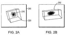
- FIGS. 2A-2Bare images showing a spherical object represented in a three-dimensional volume before ( FIG. 2A ) and after ( FIG. 2B ) an illustrative deformation, according to principles of the invention
- FIGS. 3A-3Care drawings that illustrate an embodiment of the invention relating to the selecting of an area to deform or warp ( FIG. 3A ), the selection of a location at which to apply the deformation or warp ( FIG. 3B ), and the application of a “pulling” force to the selected area at the selected location ( FIG. 3C );
- FIG. 4is a drawing that illustrates different “falloff” levels in images “a” and “b,” according to principles of the invention
- FIG. 5is a drawing that illustrates the result of a directional tugging force applied to a selected area, according to principles of the invention
- FIG. 6is a drawing that illustrates the result of applying multiple modifications to a selected area, according to principles of the invention.
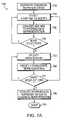
- FIG. 7Ais a flowchart showing schematically a sequence of operations during model editing according to one embodiment of the invention.
- FIG. 7Bis a flowchart showing schematically the organization of a system for three-dimensional modeling that comprises computer modules, according to one embodiment of the invention.
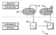
- FIG. 8is a schematic diagram showing illustrative transformations of a modified portion of a model from canonical representation to intermediate representation and back, with editing done on the intermediate representation, according to principles of the invention
- FIG. 9is a diagram showing an embodiment of an illustrative rasterization process based on surface crossings for conversion of a model from surface representation to volumetric representation according to principles of the invention.
- FIG. 10is an image of an embodiment of a menu in a computer user interface that provides access to modeling features according to systems and methods of the invention
- FIG. 11is an image of an embodiment of a control panel that allows a user to control the operation of modeling features according to systems and methods of the invention
- FIG. 12is a graph that illustrates an embodiment of a single valued-distribution function f( ⁇ ) that maps the interval [ 0 , 1 ] as a 1-to-1 mapping onto the interval [ 0 , 1 ], according to principles of the invention.
- FIGS. 13A-13Bare graphs that illustrate various relationships between a source point S and a point P 0 that the point S can influence, according to principles of the invention.
- the inventionis described with respect to an illustrative embodiment. However, it will be recognized that many alternative embodiments are possible.
- the illustrative embodimentinvolves editing a volumetric model by means of an intermediate surface representation.
- the methods of the inventionallow more flexible interactive editing of such volumetric models by supporting a wider range of standard operations, without compromising the strengths of a volumetric representation.
- One exemplary methodconsists of extracting a portion of the canonical volumetric representation into a surface representation, iteratively modifying the surface representation via a combination of mathematical and user-derived inputs, then merging the modified surface portion back into the volumetric model.
- An example of a computer that supports the systems and methods of the inventionis a commercially available general purpose computer, such as a laptop or desktop personal computer, having a central processor unit, an input device (such as a keyboard, a mouse, and/or a touch screen), an output device (such as a display screen, a printer, and/or a speaker), haptic input and output devices, and memory (such as semiconductor memory, magnetic memory such as disks and/or tapes, optical memory, and CD-ROM and DVD recording and playback devices).
- the computeroperates alone, and in other embodiments, the computer communicates over a network.
- many different computers of many different types, operating a variety of operating systemscan support the systems and methods of the invention.
- Embodiments of the inventionother than the illustrative embodiments of the invention are possible.
- the same basic processcan be applied to using a volumetric representation as the base representation and a b-spline or bezier representation as the alternative subset representation.
- a triangle or quadrilateral based meshis used as the base representation and a volumetric representation is employed as the alternative subset representation.
- Many other alternative embodimentscan be enumerated.
- a model representationcan be understood as one or more internal data structures that express the basic physical structure of the object being modeled. All other model properties can be derived from the model representation, such as for example the response of the object to a specified mechanical force having known magnitude, direction, and duration that is applied to a known location of the object.
- a visual representationcan be understood as one or more data structures used to support the provision of a visual display of the object being modeled, as well as an example of such a visual display itself.
- a visual representationcan be the data necessary to render an image on a computer monitor or on a printer, and it can be the actual image so displayed or printed.
- a canonical representationcan be understood as a standard model representation (e.g., a model conforming to a selected mathematical or logical description system) used in a particular modeling hardware and software system and associated method.
- a canonical representationcan be a description using voxels.
- An intermediate representationcan be understood as a representation in one or more data structures used temporarily during model modification, and as a corresponding image that can be displayed by any conventional display method.
- a surface representationcan be understood as a model representation consisting of an enumeration of boundary elements.
- a surface representation of an objectcan be understood as a two-dimensional representation of some portion of the object, such as a representation using a polygonal mesh, or a representation employing b-spline, bezier or other mathematical surface constructs.
- the surface representedcan be an external surface or portion thereof, an internal surface or portion thereof, or a combination of both types of surfaces.
- a volumetric representationcan be understood as a model representation based on an enumeration of volume elements, such as voxels, volumetric wavelets, and the like.
- FIGS. 1A-1Care images 100 , 102 , 104 that illustrate various three-dimensional objects having surface details.
- FIG. 1Ais an image 100 of a physical three-dimensional sculpture of a fish in a transparent medium, such as glass.
- FIG. 1Bis an image 102 displayed on a computer display of a computer-readable file intended to represent a hypothetical creature as it is being carved from a block of a solid such as clay.
- FIG. 1Cis an image 104 of a physical three-dimensional sculpture of a fish in a transparent medium, such as ice. These images are presented to provide the reader with a sense of the kind of models that can be created using prior art technology.
- the invention disclosed hereinpreserves the properties of prior art methods, and adds new capabilities that provide the ability to stretch, bend, warp, pull or tug, and non-uniformly-scale a model such as that depicted in image 102 .
- FIGS. 2A-2Bare images 200 , 202 showing a spherical object 210 represented in a three-dimensional volume 220 before ( FIG. 2A ) and after ( FIG. 2B ) an illustrative deformation.
- FIGS. 2A-2Bshow an example of a process which can be termed “surface warping,” in which the surface of a model is stretched without smoothing away details present on that surface. This provides the ability to make relatively large, global changes to models even at a stage of model development where high resolution features have been applied to the surface of the model.
- the systempermits a model of a head to be modified by puffing out the cheeks without losing facial details, or in a model of an automobile, to add some bulge to wheel wells without distorting the remainder of the vehicle.
- Thisis accomplished by converting three-dimensional elements of a volumetric model to a surface representation, for example in a polygonal surface representation, manipulating the model's polygonal surface representation, and performing a conversion of the modified surface representation back to a three-dimensional volumetric model, for example by re-rasterization to instantiate the changes in the volumetric model representation.
- the changescan optionally be visualized by providing a visual representation at any time, including in real time, as the modifications are performed by a user of the system.
- FIGS. 3A-3Care drawings 300 that illustrate an embodiment of the invention relating to the selecting of an area 310 to deform or warp ( FIG. 3A ), the selection of a location 320 at which to apply the deformation or warp ( FIG. 3B ), and the application of a “pulling” force 330 to the selected area 310 at the selected location 320 ( FIG. 3C ).
- a user of an embodiment of the systemselects the surface of the model the user wishes to warp.
- the userselects an area 310 using the paint-select mechanism of a graphical user interface, which selects a surface for either warping or smoothing.
- the selected area 310has a periphery 340 .
- the area 310 that is selectedis indicated by the user, who manipulates a cursor 350 , such as the paintbrush shown in FIG. 3A .
- the manipulationcan be accomplished using a computer pointing device such as a mouse, by using designated keys, such as the right arrow, the left arrow, the up arrow, and the down arrow keys of a computer keyboard, by use of a touch screen, or any other suitable method, including the use of a haptic interface device.
- a computer pointing devicesuch as a mouse
- designated keyssuch as the right arrow, the left arrow, the up arrow, and the down arrow keys of a computer keyboard
- a touch screenor any other suitable method, including the use of a haptic interface device.
- the userselects (or activates) the “Warp” computer command, whereupon the system creates an editable mesh corresponding to the surface selected by the user in FIG. 3A .
- the editable meshcan be generated using a polygonal, b-spline, or bezier representation, or the like.
- the selected area represented by the editable meshcan be identified to the user by being colored differently, or otherwise being visually distinct, so that the user can observe the results of his or her modifications while the user manipulates the modeled object.
- the usercan “grab” a point on the selected area 310 .
- the usergrabs the point by using a pointing device such as a mouse, and performing a “click and hold” operation with the mouse.
- the locationcan be identified to the user by a cursor 350 , such as the Hand Tool shown in FIG. 3B .
- the usercan manipulate the selected area 310 , which manipulation is performed mathematically upon the editable mesh. For example, the user can move or drag the selected area 310 around in three-dimensional space, with the periphery 340 of the area 310 fixed by application of a constraint at the coordinates that exist at the time the area 310 is selected.
- the editable mesh“warps” to maintain a surface 345 that starts from the periphery 340 of the selected area 310 and continues through the point 320 being dragged about in three-dimensional space.
- FIG. 4is a drawing 400 that illustrates different “falloff” levels in images “a” 410 and “b” 420 .
- the systemmay include a default value for the falloff parameter, which is invoked automatically by the system.
- the falloff parameter that is used to generate the surface between the selected point 320 and the periphery 340 of the selected area 310is controllable by the user.
- shape “a” 410has a large rate of falloff
- shape “b” 420has a smaller rate of falloff.
- the rate of fall-offcan be controlled by the user by entry of a value, by pressing a designated key of a keyboard to increase or decrease the rate of falloff, or by a similar interaction with the system.
- the userWhen the user is satisfied with the shape of the editable mesh, the user presses a key or otherwise selects a menu entry that indicates that the then current representation of the modified area 310 is acceptable, whereupon the modeling system transforms the intermediate representation used in modifying the model into the corresponding portion of the model representation. In some embodiments, the system re-rasterizes the intermediate model into the corresponding portion of the model representation.
- FIG. 5is a drawing 500 that illustrates the result of a directional tugging force applied to a selected area 310 .
- the cursor 350represented by the Hand Tool, is manipulated by the user in a direction other than along a normal to the planar surface defined by the periphery 340 of the selected area 310 .
- the motion of the cursor 350can be linear or curvilinear.
- the resulting shape of the selected area 310is a peaked volume 510 , such as may be obtained by dipping one's finger into a mound of shaving cream and pulling upward and sideward.
- the systemperforms the operations of transforming the intermediate representation to a model representation, as discussed with regard to FIG. 4 .
- FIG. 6is a drawing 600 that illustrates the result of applying multiple modifications to a selected area 310 .
- the usercan perform an operation such as is described with respect to FIG. 5 , and can then perform a second operation, for example, by application of a pulling or tugging force at a new point 610 .
- the resulting volume 620can have characteristics that represent the first modification further modified by the second modification. Because the modification process can be performed iteratively, it is possible to apply as many discrete modifications as the user of the system elects to perform.
- the systemperforms the operations of transforming the intermediate representation to a model representation, as discussed with regard to FIG. 4 .
- the intermediate representationis used to alter the model representation automatically upon each user edit.
- FIG. 7Ais a flowchart 700 showing schematically a sequence of operations during model editing.
- an illustrative method for editing a modelincludes the steps of generating the canonical volumetric representation, and optionally, generating a visual representation corresponding to the canonical volumetric representation.
- the methodincludes specifying at least a portion of the model to be modified. The specification can be performed manually or by automatic methods.
- the methodincludes converting the selected portion of the volumetric model into a surface representation.
- the methodcan optionally include updating the visual representation accordingly.
- the methodincludes modifying the surface representation using a combination of interactively specified user inputs and mathematical manipulation according to algorithmic processes encoded into the system.
- the methodincludes transforming the modified surface representation and incorporating the modified representation into the canonical volumetric representation.
- the methodoptionally includes updating the visual representation and optionally displaying the visual representation for the user.
- the step 710 of generating the canonical volumetric representationinvolves converting information about an object into a mathematical representation in a form expected by the system, which for the purposes of this discussion is the standard form.
- the systemcan optionally compute a visual representation of the object that is being modeled, and can optionally display a corresponding visual representation to the user.
- the computation of the visual representationis performed automatically by the system.
- the display of the visual representationis performed automatically by the system.
- the computation and the displayare performed in response to a command from a user.
- the original volumetric representationcan come from a variety of sources.
- the volumetric representationcomes from tomographic data (three-dimensional scans) or surface scans that have been converted into volumetric form.
- the volumetric representationis the output of a prior sequence of manual or automatic volumetric editing steps.
- the representationis a volumetric representation (e.g., a voxel grid) that enumerates the contents of the object to be modeled at every point in three-dimensional space.
- a visual representationis derived from the volumetric representation to allow the model to be viewed.
- the visual representationincludes one or more data structures to support a direct rendering method such as ray casting.
- the visual representationincludes a secondary non-volumetric derived representation, such as an isosurface.
- the step 720 of selecting or specifying of a portion of the model to be modifiedcan be performed under manual control by the user or alternatively can be performed by automatic specification by the system.
- a portion of the volumetric representation of the modelis selected for modification.
- the selection step 720can include, but is not limited to, specification of a sub-volume using an interactively positioned tool with a region of influence.
- the interactively positioned toolis a user controlled stylus, and the region of influence is determined by a user-controllable radius.
- the position specification of a portion of the model to be modifiedis performed in conjunction with the projection of a user-positionable two-dimensional image onto the model.
- the specification of a portion of the model to be modifiedis accomplished by drawing a closed curve on the region to be modified, for example using a pointing device such as a mouse or a stylus.
- the interactively positionable toolis a haptic interface device.
- the step 730 of converting the selected portion of the volumetric model into an intermediate surface representationis performed automatically by the system, using algorithmic mathematical manipulations. Upon specification of the portion of the model to be modified, the system converts the specified portion into the intermediate representation. In some embodiments, the selected portion of an isosurface is converted into a freely deformable polygonal mesh. In another embodiment, the selected portion of an isosurface is extracted into one or more NURBS patches.
- the step 730optionally includes updating the visual representation at the same time, to allow visual display during modification. For example, if modifications will be displayed by deforming an extracted polygonal mesh, the corresponding portion of the original isosurface typically should not be displayed at the same time, in order to avoid confusing the user.
- the step 730further includes updating the intermediate surface representation of the selected portion of the model with a second or later selected portion.
- the optional visual representationis updated accordingly.
- the step 740includes obtaining from the user an indication of whether more selections of portions of the model for modification are contemplated, and if so, repeating steps 720 and 730 as many times as may be required. When the user indicates that no additional portions of the model are intended to be modified, the system proceeds to making the modifications, at step 750 .
- the step 750 of specifying the modification to be performed on the intermediate surface representationis accomplished by obtaining specifications from the user.
- the specified modificationsinclude pulling a portion of the surface from its original location toward an interactively specified new location in three-dimensional space, raising or lowering the surface representation, or raising or lowering the portion of the surface lying within a previously specified closed curve on the model by a user-specified distance.
- the usercan use a two-dimensional image to specify an amount of displacement.
- constraintscan be applied to the specified modification to limit the amount of deformation that takes place.
- the step 760 of modifying the intermediate representationcan be performed using a combination of mathematical and interactively specified inputs.
- the usercan interactively specify further modifications, as indicated at step 770 .
- the usercan additionally return to step 720 to select a new portion of the model to modify, or the user may continue to the next step 780 .
- the systemincorporates the modified surface into the canonical volumetric representation and optionally updates the visual representation.
- the modified portions of the surface representationare reincorporated into the canonical volume representation.
- the canonical representationcomprises voxels and an intermediate representation comprises a polygonal mesh.
- the displaced surfaceis analyzed for surface crossings, which are locations where adjacent voxels lie on opposite sides of the displaced surface. Voxels can be classified as in or out based on the number of such crossings they experience, and may be assigned more precise non-binary values by incorporating information about the distance from each voxel to the crossings that influence it.
- FIG. 7Bis a flowchart 702 showing schematically the organization of a system for three-dimensional modeling that comprises computer modules.
- an illustrative system for three-dimensional modelingincludes modules that control the steps of a computer modeling process.
- a virtual objectis stored within a computer, for example in conjunction with a haptic interface or virtual reality environment.
- a representation module 705controls how the computer represents a virtual object as a volumetric model.
- a conversion module 715converts some (a subset) or all of the volumetric model into an alternative model.
- the virtual objectis subjected to at least one stimulus. The stimulus can be applied by a user.
- a subsetcan include, as examples, the entire set, a portion of the entire set, or none of the entire set.
- An analytical module 725determines a response of the alternative representation to at least one stimulus.
- Analytical module 725modifies the surface representation using a combination of interactively specified user inputs and mathematical manipulation according to algorithmic processes encoded into the system.
- a modification module 735modifies the volumetric representation so as to represent the response of the alternative representation of the virtual object to the stimulus. Modification module 735 controls transformation of the modified surface representation and incorporation of the modified representation into the volumetric representation.
- the systemincludes a second transformation module 745 that controls the transformation of the alternative representation into a third representation, The system can also include another modification module 755 that controls the modification of the third representation.
- the systemcan optionally also include a transformation module 765 that transforms the modified third representation to a modified volumetric representation.
- the systemoptionally includes modules that update the visual representation and optionally display the visual representation for the user, such as display module 775 .
- the systemcomprises a display module 775 that displays the modified alternative representation and/or the modified volumetric representation to a user from time to time.
- the systemcomprises a haptic force feedback interface that applies a haptic feedback force to a user in conjunction with a force application module 785 .
- the systemallows the user or a computer to specify at least a portion of the model to be modified. The specification can be performed manually or by automatic methods.
- the computer modulescontrol the conversion of the selected portion of the volumetric model into an alternative representation, such as a surface representation, a set-of triangles representation, a polygon set, a bezier surface, a b-spline surface, a procedural surface, and a NURBS representation.
- a procedural surfaceis one which is expressed or defined by a mathematical process or procedure. For example, a procedural surface could be defined as the surface two units of measure above the floor of a room and two units of measure above any objects resting on that floor. One procedural surface results if a basketball were left on the floor, while a different procedural surface results if a rollerskate were left on the floor. Either procedural surface changes if the object on the floor moves.
- the representation module 705that controls or performs the process of representing the virtual object as a multidimensional (for example, volumetric) model converts information about an object into a mathematical representation in a form expected by the system, which for the purposes of this discussion is the standard form.
- the systemcan optionally compute a visual representation of the object that is being modeled, and can optionally display a corresponding visual representation to the user.
- the computation of the visual representationis performed automatically by the system.
- the display of the visual representationis performed automatically by the system.
- the computation and the displayare performed in response to a command from a user.
- the conversion module 715controls the selection or specification of a portion of the model to be modified.
- the selection or specificationcan be performed under manual control by the user or alternatively can be performed by automatic specification by the system.
- a portion of the volumetric representation of the modelis selected for modification.
- the selectioncan include, but is not limited to, specification of a sub-volume using an interactively positioned tool with a region of influence.
- the interactively positioned toolis a user controlled stylus, and the region of influence is determined by a user-controllable radius.
- the position specification of a portion of the model to be modifiedis performed in conjunction with the projection of a user-positionable two-dimensional image onto the model.
- the specification of a portion of the model to be modifiedis accomplished by drawing a closed curve on the region to be modified, for example using a pointing device such as a mouse or a stylus.
- the useremploys a haptic interface device to designate the portion of the model to be modified,
- the conversion module 715converts the selected portion of the multi-dimensional model, such as a volumetric model, into an intermediate representation, such as a surface representation.
- the conversionis performed automatically by the system, using algorithmic mathematical manipulations.
- the systemUpon specification of the portion of the model to be modified, the system converts the specified portion into the intermediate representation.
- the selected portion of an isosurfaceis converted into a freely deformable polygonal mesh.
- the selected portion of an isosurfaceis extracted into one or more NURBS patches.
- the conversion module 715optionally includes the ability to update the visual representation at the same time, to allow visual display 775 during modification. For example, in one embodiment, if modifications will be displayed by deforming an extracted polygonal mesh, the corresponding portion of the original isosurface typically should not be displayed at the same time, in order to avoid confusing the user. As is understood in the software arts, the visual updating can be performed by invoking a module such as the display module 775 as a subroutine.
- the conversion module 715further includes updating the intermediate surface representation of the selected portion of the model with a second or later selected portion.
- the optional visual representationis updated accordingly.
- the analytical module 725specifies the modification to be performed on the intermediate surface representation.
- the specified modificationsinclude pulling a portion of the surface from its original location toward an interactively specified new location in three-dimensional space, raising or lowering the surface representation, or raising or lowering the portion of the surface lying within a previously specified closed curve on the model by a user-specified distance.
- the usercan use a two-dimensional image to specify an amount of displacement.
- the modification of the intermediate representationcan be performed using a combination of mathematical and interactively specified inputs.
- the modificationcan be limited by application of one or more constraints that limit the magnitude of a displacement of the model,
- the usercan interactively specify further modifications.
- the usercan additionally select a new portion of the model to modify.
- the modification module 735incorporates the modified surface into the volumetric representation.
- display module 775updates the visual representation.
- the modification module 735can call the display module 775 as a subroutine.
- the display module 775is activated by a command from the user.
- the modified portions of the surface representationare reincorporated into the volumetric representation.
- the volumetric representationcomprises voxels and an intermediate representation comprises a polygonal mesh.
- the displaced surfaceis analyzed for surface crossings, which are locations where adjacent voxels lie on opposite sides of the displaced surface. Voxels can be classified as in or out based on the number of such crossings they experience, and may be assigned more precise non-binary values by incorporating information about the distance from each voxel to the crossings that influence it.
- the various modulescan often be used repeatedly in any one session. As indicated in FIG. 7B , the system can allow a user to complete a modification of a representation, and can then return to the conversion module 715 in order to select a further subset or portion of the model for further modification. As will be appreciated by those of skill in the software arts, a module that embodies a particular set of instructions that perform a specific logical operation or group of operations often can be duplicated in hard-wired circuitry, or in a combination of software and hard-wired circuitry, in a manner which is completely transparent to a user.
- one or more modulescan be provided in hard-wired form or can be provided as a pre-programmed chip in order to assure that a particular instruction or set of instructions is performed in the same manner, independent of user input or user manipulation.
- FIG. 8is a schematic diagram 800 showing illustrative transformations of a modified portion of a model from canonical to intermediate representation and back, with editing done in the intermediate representation.
- a canonical volumetric representation 801 of an objectis provided.
- a bounding box 811indicates a region of the representation 801 has been selected for modification.
- the region in the bounding box 811is expressed in an intermediate surface representation 802 .
- the userspecifies one or more modifications of the object that cause the transformation of representation 802 to the modified intermediate surface representation 803 .
- the systemconverts the modified intermediate surface representation 803 into the modified volumetric representation 804 .
- the systemoptionally computes and optionally displays visual representations corresponding to representations 801 , 802 , 803 , and 804 for the convenience of the user.
- FIG. 9is a diagram 900 showing an embodiment of an illustrative rasterization process based on surface crossings for conversion of a model from a surface representation to a volumetric representation.
- FIG. 9depicts a cross section through a surface representation superimposed on a grid of voxels defined on a square lattice.
- the curvilinear line 930denotes the locus of points that represent the surface representation. After application of a transformation, some of the points 910 , shown in filled circles, fall to one side of the surface. Other points 920 lie on the other side of the surface.
- the systemcan then compute the required three-dimensional values for representing the appropriate volume in the three-dimensional canonical representation, for modification of a modeled object.
- FIG. 10is an image 1000 of an embodiment of a menu in a computer user interface that provides access to modeling features.
- a computer user interface having a “look and feel” similar to one or more of the well-known WindowsTM (WindowsTM is a trademark of the Microsoft Corporation, Redmond, Wash., USA) applicationsis depicted.
- WindowsTMis a trademark of the Microsoft Corporation, Redmond, Wash., USA
- user interfaces of different types, having a different “look and feel,”are possible, as will be appreciated by those of ordinary skill in the computer programming arts.
- the illustrative interfacehas a menu item denoted by the term “Tools” 1010 .
- a subcategory of toolsis denoted by “Special Effects” 1020 .
- Tug 1030Individual special effects are indicated by the menu items “Tug” 1030 , which will be described in greater detail below, and by “Spikes” 1040 .
- the usercan invoke an individual special effect by successively activating the sequence of items Tools 1010 , Special Effects 1020 , Tug 1030 using a pointing device such as a mouse, a touch pad, a touch screen, or a light pen, or by issuing the sequence of keyboard commands Control-T ( ⁇ CTRL>-T), Control-E, and Control-T, based on the underscored letter of the corresponding command.
- a userhas issued the appropriate commands, the Tug functionality of the system is activated, and the user is presented with an instance of illustrative FIG. 11 .
- “Tug”is an effect that is accessed through the Tools->Special Effects->Tug menu as described above. In one embodiment, this brings the system into a mode where a cursor 350 normally represented by an icon having the shape of a hand is replaced with a transparent clay-colored sphere with a red center point.
- the cursor displayindicates to the user that the “Tug” functionality is active, and can show the user the effects that commands issued by the user will have on the object that is being modeled.
- the sphereindicates the region of the model that will be modified using a falloff function centered at the red point.
- the default falloff functionmay be determined empirically.
- the curve that is implementedis essentially a bell curve. It is chosen because it provides an esthetically pleasing taper to the edge of a selected region and multiple tug operations can be performed with good resolution in the valley that results between successive tug operations, as indicated previously in conjunction with FIG. 6 .
- the userplaces the sphere on the model, thereby selecting a region to modify, and then holds the button on a haptic feedback system stylus to activate the tug operation, and modifies the model by applying tugs to the clay.
- the systemprovides a spring force to help control the placement of the sphere.
- the surface modelupdates in real-time. When the stylus button is released, the modified polygons stay in their then-current positions.
- the visual representationis updated to provide visual feedback to the user in real time. The user can continue to modify the surface by repeating the sequence of commands.
- FIG. 11is an image 1100 of an embodiment of a control panel that allows a user to control the operation of modeling features of the Tug functionality.
- Image 1100is a software control called a dynabar.
- the dynabar 1100includes a button 1110 labeled “Nudge,” a text box 1120 in which the user can enter numerical values, an increment arrow 1130 and a decrement arrow 1140 that can be used to modify the value in text box 1120 , a button 1150 labeled “Done” that permits the user to accept the effects of one or more modifications, and a button 1160 labeled “Reset” that cancels all modifications since the latest action selected from the group consisting of invoking the tug functionality and activating the “Done” button 1150 .
- the modelis re-rasterized to incorporate any changes that have been made. If no changes have been made or the model has been reset or all changes have been undone, the button is unavailable, e.g., it is displayed in a “grayed-out” visual representation. Activation of the Done button 1150 does not cause the Tug functionality to terminate.
- the Reset button 1160undoes all changes that have been made since entering the tug environment or since the last “Done” command. It is unavailable when the “Done” command is unavailable.
- the diameter of the spherecan be changed through a text field within a range of values having the current dimensional units, through use of the increment and decrement arrow buttons 1130 , 1140 , or continuous tool resize using a selected keyboard key, such as the “[” key.
- the Reset button 1160undoes all of the changes to the surface model.
- the Nudge button 1110attenuates the motion of the surface model to aid in making precise changes.
- the operation of the Nudge button 1110is more fully described in the U.S. provisional patent application Ser. No. 60/255,530, filed Dec. 14, 2000, entitled “Systems and Methods for Three-Dimensional Modelling.” Activation of the Done button 1150 incorporates the changes into the model.
- FIG. 12is a graph 1200 that illustrates an embodiment of a single valued-distribution function f( ⁇ ) 1210 that maps the interval [ 0 , 1 ] along the horizontal axis 1220 as a 1-to-1mapping onto the interval [ 0 , 1 ] along the vertical axis 1230 .
- a single-valued functionis one that has a single dependent value y for each discrete independent value x.
- the functioncan be a sigmoidal function as shown in FIG. 12 .
- FIGS. 13A-13Bare graphs 1300 , 1302 that illustrate various relationships between a source point S 1310 and a point P 0 1320 that the point S can influence.
- the systemcan perform smoothing without losing details that exist in a model.
- the smoothing operationproduces locally fair surfaces. This new operation also can be used to repair and/or clean up input files for editing.
- the algorithmuses as inputs a closed boundary on the isosurface of the model, a complexity factor that establishes the baseline for the desired result of smoothing, a smoothing factor in [ 0 , 1 ] that establishes the amount of desired smoothing for the target patch calculated from the initial patch, and a fall-off function that allows the smoothing effect to gradually taper to zero at the initial patch boundary.
- the closed boundary on the isosurface of the modelis a four-sided patch boundary.
- the closed boundaryis an arbitrarily shaped region.
- the isosurface triangle data within the boundaryis referred to as the initial patch.
- the complexity factor that establishes the baseline for the desired result of smoothingis in [ 0 , 1 ] where 0 indicates the initial patch contains little surface detail to be modeled and 1 indicates the initial patch has a lot of surface detail to be modeled.
- the smoothing factoris in [ 0 , 1 ] that establishes the amount of desired smoothing for the target patch calculated from the initial patch.
- a factor of 0indicates no smoothing and a value of 1 indicates maximal smoothing.
- the fall-off function that allows the smoothing effect to gradually taper at the initial patch boundaryis described as a factor in [ 0 , 1 ] where 0 indicates no fall-off and 1 indicates a maximum default fall-off. In other embodiments, this fall-off function is an arbitrarily shaped, force-based function applied to the isosurface.
- the command issued by a userincludes defining the boundary and interactively and iteratively adjusting the complexity factor, the smoothing factor, and the fall-off function until the resulting output is satisfactory.
- the boundaryis defined by interactive tracing on the surface.
- the complexity factoris adjusted much less frequently than the smoothing factor and fall-off function.
- these controlsare simple sliders. After each change, the user is shown a simulation of the result that will be achieved if the operation is executed. In alternative embodiments, the command provides “before-and-after” control for assessing the visual change.
- the algorithmmodels the initial patch with two mathematical descriptions, including a baseline surface model and a displacement map in the u-v unit square.
- the baseline surface modelis a mathematical interpolation of the triangle vertices.
- a known approach to such surface fitting problemsis the use of least-squares fits to NURBS surfaces.
- the baseline surfaceis then a parametric definition S(u,v) where u,v ⁇ [ 0 , 1 ].
- the number of control points defining Sis established by the complexity factor.
- a set of well-behaved isocurvesis generated along the initial patch, and the isocurve intersections become the targets of the interpolation. This set of intersections is referred to as the baseline grid.
- the displacement map in the u-v unitsquare tracks the “error” between the initial patch and the baseline surface model.
- This displacement mapis referred to as the three-dimensional vector valued function D(u,v).
- each point of the baseline gridshould equal S(u,v)+D(u,v) for the (u,v) coordinates that correspond to that grid point. That is, if O(u,v) represents the original triangle data at the baseline grid values, we then have: O ( u i ,v j ) ⁇ S ( u i ,v j )+ D ( u i ,v j ) at the baseline grid points (u i , v j ).
- the original patchis modeled as a smooth and fair (with moderate to low complexity factor) surface plus the bumps that occur on it.
- the fall-off functionis a scalar-valued function f(u,v) ⁇ [0,1].
- the userprovides a 1-dimensional input to generate f.
- a user value of 0no fall-off
- establishes f(u,v)1 for all u,v.
- T(u,v)approaches O(u,v) regardless of f(u,v).
- the surface described by T(u,v)is then re-rasterized back into the canonical model, which is a voxel model.
- the algorithmis implemented by performing the steps of tracing the outline on the isosurface, determining a baseline grid, interpolating to find S(u,v), calculating D(u,v), calculating f(u,v), calculating T(u,v), and re-rasterizing the result for incorporation into the canonical model.
- the surface tug algorithmcan be expressed as follows.
- the effect within the spherefalls off with a “tapered” shape (i.e., the effect increases the closer one gets to P 0 ).
- f( ⁇ )will change for various effects and could be a discrete curve interpolated from any ⁇ in [ 0 , 1 ].
- one embodimentinvolves space warping. In some embodiments this can be accomplished using methods for moving a surface. In one embodiment, vertices are pushed. Such a method can involve resampling of polygons if high curvature exists, and does not prevent foldover. In one embodiment, volumes are resampled. This approach maintains valid volumes.
- a frontpropagates.
- This embodimentis a hybrid between a vertex-based method and a volumetric method. It is volumetric over a limited domain.
- Other embodimentsinvolve warping by use of three-dimensional control points, such as a matrix or tri-cubic representation.
- Still other embodimentsinvolve warping by use of a proxy object such as a point, a space curve, a polynomial expression, or the like.
Landscapes
- Engineering & Computer Science (AREA)
- Theoretical Computer Science (AREA)
- General Engineering & Computer Science (AREA)
- Physics & Mathematics (AREA)
- General Physics & Mathematics (AREA)
- Computer Graphics (AREA)
- Software Systems (AREA)
- Architecture (AREA)
- Computer Hardware Design (AREA)
- Human Computer Interaction (AREA)
- Geometry (AREA)
- Processing Or Creating Images (AREA)
Abstract
Description
O(ui,vj)≈S(ui,vj)+D(ui,vj)
at the baseline grid points (ui, vj).
T(u,v)=(1−f(u,v))O(u,v)+f(u,v)[S(u,v)+(1−s)D(u,v)]
when s=1 (maximum smoothing), T(u,v)=S(u,v) when f(u,v)=1 (target surface is original “wrapped” to baseline surface model), and T(u,v)=O(u,v)when f(u,v)=0 (target is original at the feathered edge). As s approaches 0 (minimum smoothing), T(u,v) approaches O(u,v) regardless of f(u,v). In one embodiment, the surface described by T(u,v) is then re-rasterized back into the canonical model, which is a voxel model.
Let α=∥S−P0∥2
(representing distance squared)
α≧r2=>S is unchanged, or T=S.
α<r2
T=S+f(1−γ)D
Claims (15)
Priority Applications (1)
| Application Number | Priority Date | Filing Date | Title |
|---|---|---|---|
| US11/179,038US7710415B2 (en) | 2001-01-08 | 2005-07-11 | Systems and methods for three-dimensional modeling |
Applications Claiming Priority (3)
| Application Number | Priority Date | Filing Date | Title |
|---|---|---|---|
| US26027801P | 2001-01-08 | 2001-01-08 | |
| US10/017,148US6958752B2 (en) | 2001-01-08 | 2001-12-14 | Systems and methods for three-dimensional modeling |
| US11/179,038US7710415B2 (en) | 2001-01-08 | 2005-07-11 | Systems and methods for three-dimensional modeling |
Related Parent Applications (1)
| Application Number | Title | Priority Date | Filing Date |
|---|---|---|---|
| US10/017,148ContinuationUS6958752B2 (en) | 2001-01-08 | 2001-12-14 | Systems and methods for three-dimensional modeling |
Publications (2)
| Publication Number | Publication Date |
|---|---|
| US20060109269A1 US20060109269A1 (en) | 2006-05-25 |
| US7710415B2true US7710415B2 (en) | 2010-05-04 |
Family
ID=26689521
Family Applications (2)
| Application Number | Title | Priority Date | Filing Date |
|---|---|---|---|
| US10/017,148Expired - LifetimeUS6958752B2 (en) | 2001-01-08 | 2001-12-14 | Systems and methods for three-dimensional modeling |
| US11/179,038Expired - LifetimeUS7710415B2 (en) | 2001-01-08 | 2005-07-11 | Systems and methods for three-dimensional modeling |
Family Applications Before (1)
| Application Number | Title | Priority Date | Filing Date |
|---|---|---|---|
| US10/017,148Expired - LifetimeUS6958752B2 (en) | 2001-01-08 | 2001-12-14 | Systems and methods for three-dimensional modeling |
Country Status (1)
| Country | Link |
|---|---|
| US (2) | US6958752B2 (en) |
Cited By (10)
| Publication number | Priority date | Publication date | Assignee | Title |
|---|---|---|---|---|
| US20080192049A1 (en)* | 2007-02-13 | 2008-08-14 | Thomas Schiwietz | Image deformation using physical models |
| US20080246761A1 (en)* | 2006-11-30 | 2008-10-09 | Daniel Faken | Systems for hybrid geometric/volumetric representation of 3d objects |
| US20090006043A1 (en)* | 2007-05-06 | 2009-01-01 | Universitatsklinikum Hamburg-Eppendorf | Method for the simulation of the haptic of an interaction of a guided object with a virtual three-dimensional object |
| US20090043425A1 (en)* | 2007-08-10 | 2009-02-12 | Fanuc Ltd | Robot program adjusting system |
| US20120029883A1 (en)* | 2010-07-30 | 2012-02-02 | Straumann Holding Ag | Computer-implemented method for virtually modifying a digital model of a dental restoration and a computer-readable medium |
| US9030411B2 (en) | 2004-06-29 | 2015-05-12 | 3D Systems, Inc. | Apparatus and methods for haptic rendering using a haptic camera view |
| US20160224693A1 (en)* | 2015-02-02 | 2016-08-04 | Dassault Systemes | Engraving a 2d image on a subdivision surface |
| US20160240014A1 (en)* | 2015-02-17 | 2016-08-18 | Hewlett-Packard Development Company, L.P. | Display three-dimensional object on browser |
| US9835568B2 (en)* | 2016-04-12 | 2017-12-05 | General Electric Company | Defect correction using tomographic scanner for additive manufacturing |
| US10877561B2 (en) | 2017-08-22 | 2020-12-29 | Interdigital Ce Patent Holdings | Haptic immersive device with touch surfaces for virtual object creation |
Families Citing this family (72)
| Publication number | Priority date | Publication date | Assignee | Title |
|---|---|---|---|---|
| US7225404B1 (en) | 1996-04-04 | 2007-05-29 | Massachusetts Institute Of Technology | Method and apparatus for determining forces to be applied to a user through a haptic interface |
| US6084587A (en) | 1996-08-02 | 2000-07-04 | Sensable Technologies, Inc. | Method and apparatus for generating and interfacing with a haptic virtual reality environment |
| US6552722B1 (en) | 1998-07-17 | 2003-04-22 | Sensable Technologies, Inc. | Systems and methods for sculpting virtual objects in a haptic virtual reality environment |
| US6421048B1 (en) | 1998-07-17 | 2002-07-16 | Sensable Technologies, Inc. | Systems and methods for interacting with virtual objects in a haptic virtual reality environment |
| US6765589B1 (en) | 2000-11-16 | 2004-07-20 | Adobe Systems Incorporated | Brush for warping and water reflection effects |
| US6867770B2 (en) | 2000-12-14 | 2005-03-15 | Sensable Technologies, Inc. | Systems and methods for voxel warping |
| US6958752B2 (en) | 2001-01-08 | 2005-10-25 | Sensable Technologies, Inc. | Systems and methods for three-dimensional modeling |
| US7363199B2 (en)* | 2001-04-25 | 2008-04-22 | Telekinesys Research Limited | Method and apparatus for simulating soft object movement |
| US7353149B2 (en)* | 2001-04-25 | 2008-04-01 | Telekinesys Research Limited | Method and apparatus for simulating dynamic contact of objects |
| US7337093B2 (en)* | 2001-09-07 | 2008-02-26 | Purdue Research Foundation | Systems and methods for collaborative shape and design |
| AU2002332918A1 (en)* | 2001-09-07 | 2003-03-24 | Abhishek Kumar Agrawal | Systems and methods for collaborative shape design |
| US6671651B2 (en) | 2002-04-26 | 2003-12-30 | Sensable Technologies, Inc. | 3-D selection and manipulation with a multiple dimension haptic interface |
| US7246103B2 (en)* | 2003-06-30 | 2007-07-17 | Microsoft Corporation | Probabilistic model of distraction for a virtual reality environment |
| US8456475B2 (en)* | 2003-06-30 | 2013-06-04 | Microsoft Corporation | Motion line switching in a virtual environment |
| US7358973B2 (en) | 2003-06-30 | 2008-04-15 | Microsoft Corporation | Mixture model for motion lines in a virtual reality environment |
| US20050010319A1 (en)* | 2003-07-09 | 2005-01-13 | Sukesh Patel | System and method for validating and visualizing APC assisted semiconductor manufacturing processes |
| US7312805B1 (en) | 2003-09-29 | 2007-12-25 | Adobe Systems Incorporated | User defined warping tool |
| US7095418B2 (en)* | 2003-10-30 | 2006-08-22 | Sensable Technologies, Inc. | Apparatus and methods for texture mapping |
| US7382378B2 (en)* | 2003-10-30 | 2008-06-03 | Sensable Technologies, Inc. | Apparatus and methods for stenciling an image |
| US8963958B2 (en)* | 2003-12-10 | 2015-02-24 | 3D Systems, Inc. | Apparatus and methods for adjusting a texture wrapped onto the surface of a virtual object |
| US7626589B2 (en) | 2003-12-10 | 2009-12-01 | Sensable Technologies, Inc. | Haptic graphical user interface for adjusting mapped texture |
| US7889209B2 (en) | 2003-12-10 | 2011-02-15 | Sensable Technologies, Inc. | Apparatus and methods for wrapping texture onto the surface of a virtual object |
| US7149596B2 (en) | 2004-01-13 | 2006-12-12 | Sensable Technologies, Inc. | Apparatus and methods for modifying a model of an object to enforce compliance with a manufacturing constraint |
| CN101253466A (en)* | 2004-08-02 | 2008-08-27 | 皇家飞利浦电子股份有限公司 | System and method for enabling the modeling of virtual objects |
| WO2006017612A2 (en)* | 2004-08-06 | 2006-02-16 | Sensable Technologies, Inc. | Virtual musical interface in a haptic virtual environment |
| JP4472467B2 (en)* | 2004-08-27 | 2010-06-02 | 任天堂株式会社 | Image processing program and image processing apparatus |
| WO2007054755A2 (en)* | 2004-12-03 | 2007-05-18 | Telekinesys Research Limited | Physics simulation apparatus and method |
| US7830373B1 (en)* | 2006-01-25 | 2010-11-09 | Bo Gao | System and methods of civil engineering objects model |
| EP1983412A4 (en)* | 2006-01-31 | 2011-07-20 | Kenji Yoshida | Image processing method |
| US8332188B2 (en)* | 2006-03-03 | 2012-12-11 | Solido Design Automation Inc. | Modeling of systems using canonical form functions and symbolic regression |
| CN101490717A (en)* | 2006-07-14 | 2009-07-22 | 皇家飞利浦电子股份有限公司 | A method, apparatus, system and computer-readable medium for interactive shape manipulation |
| US20080062183A1 (en)* | 2006-09-11 | 2008-03-13 | Bart Swaelens | Hybrid data structures for graphics programs |
| US8359114B2 (en)* | 2006-11-28 | 2013-01-22 | Dentsable, Inc. | Haptically enabled dental modeling system |
| KR101520649B1 (en) | 2008-01-21 | 2015-05-15 | 삼성전자 주식회사 | 3 Method and system for compressing and decoding mesh data with random accessibility in 3-dimensional mesh model |
| US8358302B2 (en)* | 2008-04-22 | 2013-01-22 | International Business Machines Corporation | Dynamic creation of virtual regions |
| US20100066731A1 (en)* | 2008-09-16 | 2010-03-18 | James Calvin Vecore | Configurator Process and System |
| KR101545736B1 (en)* | 2009-05-04 | 2015-08-19 | 삼성전자주식회사 | Apparatus and method for generating three-dimensional content in a portable terminal |
| US20110066406A1 (en)* | 2009-09-15 | 2011-03-17 | Chung Yuan Christian University | Method for Generating Real-Time Haptic Response Information for a Haptic Simulating Device |
| JP5357685B2 (en)* | 2009-09-28 | 2013-12-04 | 株式会社ソニー・コンピュータエンタテインメント | 3D object processing apparatus, 3D object processing method, program, and information storage medium |
| US9734629B2 (en) | 2010-02-26 | 2017-08-15 | 3D Systems, Inc. | Systems and methods for creating near real-time embossed meshes |
| US9959666B2 (en)* | 2010-05-13 | 2018-05-01 | 3D Systems, Inc. | Method and apparatus for adding detail to a 3D solid model using a secondary geometric representation |
| US20120065755A1 (en) | 2010-08-13 | 2012-03-15 | Sensable Technologies, Inc. | Fabrication of non-homogeneous articles via additive manufacturing using three-dimensional voxel-based models |
| US8849015B2 (en) | 2010-10-12 | 2014-09-30 | 3D Systems, Inc. | System and apparatus for haptically enabled three-dimensional scanning |
| US9119655B2 (en) | 2012-08-03 | 2015-09-01 | Stryker Corporation | Surgical manipulator capable of controlling a surgical instrument in multiple modes |
| US9921712B2 (en) | 2010-12-29 | 2018-03-20 | Mako Surgical Corp. | System and method for providing substantially stable control of a surgical tool |
| US9802364B2 (en) | 2011-10-18 | 2017-10-31 | 3D Systems, Inc. | Systems and methods for construction of an instruction set for three-dimensional printing of a user-customizableimage of a three-dimensional structure |
| US9830743B2 (en)* | 2012-04-03 | 2017-11-28 | Autodesk, Inc. | Volume-preserving smoothing brush |
| US9226796B2 (en) | 2012-08-03 | 2016-01-05 | Stryker Corporation | Method for detecting a disturbance as an energy applicator of a surgical instrument traverses a cutting path |
| US9820818B2 (en) | 2012-08-03 | 2017-11-21 | Stryker Corporation | System and method for controlling a surgical manipulator based on implant parameters |
| CN107198567B (en) | 2012-08-03 | 2021-02-09 | 史赛克公司 | Systems and methods for robotic surgery |
| US20140267425A1 (en)* | 2013-03-15 | 2014-09-18 | Crayola Llc | Personalized Digital Animation Kit |
| US10475226B2 (en) | 2013-03-15 | 2019-11-12 | Crayola Llc | Coloring kit for capturing and animating two-dimensional colored creation |
| US9946448B2 (en) | 2013-03-15 | 2018-04-17 | Crayola Llc | Coloring kit for capturing and animating two-dimensional colored creation |
| US9305391B2 (en) | 2013-03-15 | 2016-04-05 | 3D Systems, Inc. | Apparatus and methods for detailing subdivision surfaces |
| US9626789B2 (en)* | 2013-05-07 | 2017-04-18 | Advanced Micro Devices, Inc. | Implicit texture map parameterization for GPU rendering |
| JP6410023B2 (en)* | 2013-09-06 | 2018-10-24 | パナソニックIpマネジメント株式会社 | Master-slave robot control device and control method, robot, master-slave robot control program, and integrated electronic circuit for master-slave robot control |
| US20150103077A1 (en)* | 2013-10-14 | 2015-04-16 | Schlumberger Technology Corporation | Intersection avoidance in mesh editing |
| KR20160024552A (en)* | 2014-08-26 | 2016-03-07 | 삼성전자주식회사 | Method and apparatus for modeling deformable body comprising particles |
| US20160092041A1 (en)* | 2014-09-29 | 2016-03-31 | Madesolid, Inc. | System and method to facilitate material selection for a three dimensional printing object |
| US10339266B2 (en)* | 2016-02-16 | 2019-07-02 | Board Of Regents Of The University Of Texas Systems | Mechanisms for constructing spline surfaces to provide inter-surface continuity |
| US11030363B2 (en) | 2016-05-25 | 2021-06-08 | Microsoft Technology Licensing, Llc | Physics engine with permissive rigid body penetration |
| US20180114368A1 (en)* | 2016-10-25 | 2018-04-26 | Adobe Systems Incorporated | Three-dimensional model manipulation and rendering |
| US11202682B2 (en) | 2016-12-16 | 2021-12-21 | Mako Surgical Corp. | Techniques for modifying tool operation in a surgical robotic system based on comparing actual and commanded states of the tool relative to a surgical site |
| USD819658S1 (en)* | 2017-01-03 | 2018-06-05 | Faraday & Future Inc. | Vehicle display screen or portion thereof with animated graphical user interface |
| JP6969149B2 (en) | 2017-05-10 | 2021-11-24 | 富士フイルムビジネスイノベーション株式会社 | 3D shape data editing device and 3D shape data editing program |
| KR101856426B1 (en)* | 2017-11-27 | 2018-06-20 | 세종대학교산학협력단 | 3D geometry enhancement method and apparatus thereof |
| WO2019164497A1 (en)* | 2018-02-23 | 2019-08-29 | Sony Mobile Communications Inc. | Methods, devices, and computer program products for gradient based depth reconstructions with robust statistics |
| US10740986B2 (en)* | 2018-08-30 | 2020-08-11 | Qualcomm Incorporated | Systems and methods for reconstructing a moving three-dimensional object |
| CN111626803A (en)* | 2019-02-28 | 2020-09-04 | 北京京东尚科信息技术有限公司 | Method and device for customizing article virtualization and storage medium thereof |
| US10878641B1 (en)* | 2019-06-07 | 2020-12-29 | Adobe Inc. | Editing bezier patch by selecting multiple anchor points |
| CN111161409B (en)* | 2019-12-27 | 2023-10-13 | 中国航空工业集团公司沈阳飞机设计研究所 | Aircraft guarantee equipment verification system |
| CN116049925B (en)* | 2023-02-01 | 2025-06-06 | 大连理工大学 | Adaptive geometric modeling method for composite thin-walled component structures for integrated modeling-analysis-optimization |
Citations (171)
| Publication number | Priority date | Publication date | Assignee | Title |
|---|---|---|---|---|
| US2475484A (en) | 1946-05-14 | 1949-07-05 | Nise Dwight Dee De | Method and means for imparting feel back to a manually-movable control element |
| US3168203A (en) | 1960-07-07 | 1965-02-02 | Gen Mills Inc | Manually operated hydraulic actuator control having feel-back |
| US3263824A (en) | 1963-12-20 | 1966-08-02 | Northrop Corp | Servo controlled manipulator device |
| US3449008A (en) | 1967-06-08 | 1969-06-10 | Gen Dynamics Corp | Object handling system with remote manual control |
| US3531868A (en) | 1968-04-18 | 1970-10-06 | Ford Motor Co | Surface scanner for measuring the coordinates of points on a three-dimensional surface |
| US3618786A (en) | 1969-01-02 | 1971-11-09 | Gen Electric | Material-handling apparatus with end effector force resolver and feedback |
| US3637092A (en) | 1970-04-30 | 1972-01-25 | Gen Electric | Material-handling apparatus |
| US3920972A (en) | 1974-07-16 | 1975-11-18 | Cincinnati Milacron Inc | Method and apparatus for programming a computer operated robot arm |
| US3944798A (en) | 1974-04-18 | 1976-03-16 | Eaton-Leonard Corporation | Method and apparatus for measuring direction |
| US4062455A (en) | 1976-11-22 | 1977-12-13 | Flatau Carl R | Remote manipulator |
| US4150803A (en) | 1977-10-05 | 1979-04-24 | Fernandez Carlos P | Two axes controller |
| US4216467A (en) | 1977-12-22 | 1980-08-05 | Westinghouse Electric Corp. | Hand controller |
| US4302138A (en) | 1978-02-01 | 1981-11-24 | Alain Zarudiansky | Remote handling devices |
| US4367532A (en) | 1979-10-12 | 1983-01-04 | Nordson Corporation | Manually programmable robot with power-assisted motion during programming |
| US4420808A (en) | 1980-04-01 | 1983-12-13 | United Technologies Corporation | Multi-axis force stick, self-trimmed aircraft flight control system |
| US4521685A (en) | 1982-03-01 | 1985-06-04 | Lord Corporation | Tactile sensor for an industrial robot or the like |
| US4604016A (en) | 1983-08-03 | 1986-08-05 | Joyce Stephen A | Multi-dimensional force-torque hand controller having force feedback |
| US4632341A (en) | 1985-02-06 | 1986-12-30 | The United States Of America As Represented By The Secretary Of The Air Force | Stabilizing force feedback in bio-actuated control systems |
| US4638798A (en) | 1980-09-10 | 1987-01-27 | Shelden C Hunter | Stereotactic method and apparatus for locating and treating or removing lesions |
| US4653011A (en) | 1984-10-29 | 1987-03-24 | Mitutoyo Mfg. Co., Ltd. | Method of measuring by coordinate measuring instrument and coordinate measuring instrument |
| US4654648A (en) | 1984-12-17 | 1987-03-31 | Herrington Richard A | Wireless cursor control system |
| US4655673A (en) | 1983-05-10 | 1987-04-07 | Graham S. Hawkes | Apparatus providing tactile feedback to operators of remotely controlled manipulators |
| US4661032A (en) | 1984-12-20 | 1987-04-28 | Agency Of Industrial Science & Technology, Ministry Of International Trade & Industry | Bilateral master-slave manipulator control device |
| US4670851A (en) | 1984-01-09 | 1987-06-02 | Mitsubishi Denki Kabushiki Kaisha | Vector quantizer |
| US4676002A (en) | 1984-06-25 | 1987-06-30 | Slocum Alexander H | Mechanisms to determine position and orientation in space |
| US4680519A (en) | 1985-09-23 | 1987-07-14 | General Electric Co. | Recursive methods for world-to-joint transformation for a robot manipulator |
| US4686522A (en) | 1985-02-19 | 1987-08-11 | International Business Machines Corporation | Method of editing graphic objects in an interactive draw graphic system using implicit editing actions |
| US4703443A (en) | 1984-02-16 | 1987-10-27 | Kabushiki Kaisha Toshiba | Device for measuring the shape of a three-dimensional object |
| US4729098A (en) | 1985-06-05 | 1988-03-01 | General Electric Company | System and method employing nonlinear interpolation for the display of surface structures contained within the interior region of a solid body |
| US4769763A (en) | 1985-06-28 | 1988-09-06 | Carl-Zeiss-Stiftung | Control for coordinate measuring instruments |
| US4791934A (en) | 1986-08-07 | 1988-12-20 | Picker International, Inc. | Computer tomography assisted stereotactic surgery system and method |
| US4795296A (en) | 1986-11-17 | 1989-01-03 | California Institute Of Technology | Hand-held robot end effector controller having movement and force control |
| US4800721A (en) | 1987-02-13 | 1989-01-31 | Caterpillar Inc. | Force feedback lever |
| US4819195A (en) | 1987-01-20 | 1989-04-04 | The Warner & Swasey Company | Method for calibrating a coordinate measuring machine and the like and system therefor |
| US4823634A (en) | 1987-11-03 | 1989-04-25 | Culver Craig F | Multifunction tactile manipulatable control |
| US4837734A (en) | 1986-02-26 | 1989-06-06 | Hitachi, Ltd. | Method and apparatus for master-slave manipulation supplemented by automatic control based on level of operator skill |
| US4839838A (en) | 1987-03-30 | 1989-06-13 | Labiche Mitchell | Spatial input apparatus |
| US4853874A (en) | 1986-12-12 | 1989-08-01 | Hitachi, Ltd. | Master-slave manipulators with scaling |
| US4888538A (en) | 1986-05-19 | 1989-12-19 | Belorussky Gosudarstvenny Universitet Imeni V.I. Lenina | System for remote transmission of angular position and force between master and slave shafts |
| US4893981A (en) | 1987-03-26 | 1990-01-16 | Kabushiki Kaisha Komatsu Seisakusho | Master/slave type manipulator |
| US4907973A (en) | 1988-11-14 | 1990-03-13 | Hon David C | Expert system simulator for modeling realistic internal environments and performance |
| US4907970A (en) | 1988-03-30 | 1990-03-13 | Grumman Aerospace Corporation | Sidestick-type thrust control simulator |
| US4942538A (en) | 1988-01-05 | 1990-07-17 | Spar Aerospace Limited | Telerobotic tracker |
| US4945501A (en) | 1987-01-20 | 1990-07-31 | The Warner & Swasey Company | Method for determining position within the measuring volume of a coordinate measuring machine and the like and system therefor |
| US4945305A (en) | 1986-10-09 | 1990-07-31 | Ascension Technology Corporation | Device for quantitatively measuring the relative position and orientation of two bodies in the presence of metals utilizing direct current magnetic fields |
| US4961138A (en) | 1987-05-01 | 1990-10-02 | General Datacomm, Inc. | System and apparatus for providing three dimensions of input into a host processor |
| US4973215A (en) | 1986-02-18 | 1990-11-27 | Robotics Research Corporation | Industrial robot with servo |
| US4973111A (en) | 1988-09-14 | 1990-11-27 | Case Western Reserve University | Parametric image reconstruction using a high-resolution, high signal-to-noise technique |
| US4982504A (en) | 1988-02-18 | 1991-01-08 | C.E. Johansson Ab | Method for determining positional errors and for compensating for such errors, and apparatus for carrying out the method |
| US4988981A (en) | 1987-03-17 | 1991-01-29 | Vpl Research, Inc. | Computer data entry and manipulation apparatus and method |
| US5004391A (en) | 1989-08-21 | 1991-04-02 | Rutgers University | Portable dextrous force feedback master for robot telemanipulation |
| US5007300A (en) | 1989-03-03 | 1991-04-16 | United Kingdom Atomic Energy Authority | Multi-axis hand controller |
| US5019761A (en) | 1989-02-21 | 1991-05-28 | Kraft Brett W | Force feedback control for backhoe |
| US5018922A (en) | 1987-03-26 | 1991-05-28 | Kabushiki Kaisha Komatsu Seisakusho | Master/slave type manipulator |
| US5038089A (en) | 1988-03-23 | 1991-08-06 | The United States Of America As Represented By The Administrator Of The National Aeronautics And Space Administration | Synchronized computational architecture for generalized bilateral control of robot arms |
| US5040306A (en) | 1988-02-18 | 1991-08-20 | Renishaw Plc | Surface-sensing device |
| US5044956A (en) | 1989-01-12 | 1991-09-03 | Atari Games Corporation | Control device such as a steering wheel for video vehicle simulator with realistic feedback forces |
| US5053975A (en) | 1988-06-10 | 1991-10-01 | Hitachi, Ltd. | Master-slave manipulator control |
| US5072361A (en) | 1990-02-01 | 1991-12-10 | Sarcos Group | Force-reflective teleoperation control system |
| US5088055A (en) | 1989-02-22 | 1992-02-11 | Kabushiki Kaisha Okuma Tekkosho | Coordinate measuring apparatus having a stylus friction compensating means |
| US5088046A (en) | 1987-12-19 | 1992-02-11 | Renishaw Plc | Mounting for surface-sensing stylus and a method of using said mounting |
| US5103404A (en) | 1985-12-06 | 1992-04-07 | Tensor Development, Inc. | Feedback for a manipulator |
| US5105367A (en) | 1988-10-19 | 1992-04-14 | Hitachi, Ltd. | Master slave manipulator system |
| US5116180A (en) | 1988-07-18 | 1992-05-26 | Spar Aerospace Limited | Human-in-the-loop machine control loop |
| US5116051A (en) | 1989-01-12 | 1992-05-26 | Atari Games Corporation | Strain gauge pressure-sensitive video game control |
| US5130632A (en) | 1989-12-06 | 1992-07-14 | Hitachi, Ltd. | Manipulator and control method therefor |
| US5131844A (en) | 1991-04-08 | 1992-07-21 | Foster-Miller, Inc. | Contact digitizer, particularly for dental applications |
| US5143505A (en) | 1991-02-26 | 1992-09-01 | Rutgers University | Actuator system for providing force feedback to a dextrous master glove |
| US5142931A (en) | 1991-02-14 | 1992-09-01 | Honeywell Inc. | 3 degree of freedom hand controller |
| US5184319A (en) | 1990-02-02 | 1993-02-02 | Kramer James F | Force feedback and textures simulating interface device |
| US5185561A (en) | 1991-07-23 | 1993-02-09 | Digital Equipment Corporation | Torque motor as a tactile feedback device in a computer system |
| US5189806A (en) | 1988-12-19 | 1993-03-02 | Renishaw Plc | Method of and apparatus for scanning the surface of a workpiece |
| US5193963A (en) | 1990-10-31 | 1993-03-16 | The United States Of America As Represented By The Administrator Of The National Aeronautics And Space Administration | Force reflecting hand controller |
| US5204824A (en) | 1989-08-29 | 1993-04-20 | Mitutoyo Corporation | Method of and apparatus for copy controlling coordinate measuring probe with rotary table |
| US5220260A (en) | 1991-10-24 | 1993-06-15 | Lex Computer And Management Corporation | Actuator having electronically controllable tactile responsiveness |
| US5223776A (en) | 1990-12-31 | 1993-06-29 | Honeywell Inc. | Six-degree virtual pivot controller |
| US5237647A (en) | 1989-09-15 | 1993-08-17 | Massachusetts Institute Of Technology | Computer aided drawing in three dimensions |
| US5239246A (en) | 1992-07-08 | 1993-08-24 | The United States Of America As Represented By The Administrator Of The National Aeronautics And Space Administration | Force reflection with compliance control |
| US5255211A (en) | 1990-02-22 | 1993-10-19 | Redmond Productions, Inc. | Methods and apparatus for generating and processing synthetic and absolute real time environments |
| US5264768A (en) | 1992-10-06 | 1993-11-23 | Honeywell, Inc. | Active hand controller feedback loop |
| US5266875A (en) | 1991-05-23 | 1993-11-30 | Massachusetts Institute Of Technology | Telerobotic system |
| US5333257A (en) | 1991-08-09 | 1994-07-26 | C/A Architects, Inc. | System for displaying selected assembly-facility seating views |
| US5354162A (en) | 1991-02-26 | 1994-10-11 | Rutgers University | Actuator system for providing force feedback to portable master support |
| US5382885A (en) | 1993-08-09 | 1995-01-17 | The University Of British Columbia | Motion scaling tele-operating system with force feedback suitable for microsurgery |
| US5389865A (en) | 1992-12-02 | 1995-02-14 | Cybernet Systems Corporation | Method and system for providing a tactile virtual reality and manipulator defining an interface device therefor |
| US5396265A (en) | 1990-09-17 | 1995-03-07 | Massachusetts Institute Of Technology | Three-dimensional tactile computer input device |
| US5429140A (en) | 1993-06-04 | 1995-07-04 | Greenleaf Medical Systems, Inc. | Integrated virtual reality rehabilitation system |
| US5438529A (en) | 1994-01-26 | 1995-08-01 | Immersion Human Interface Corporation | Percussion input device for personal computer systems |
| US5446834A (en) | 1992-04-28 | 1995-08-29 | Sun Microsystems, Inc. | Method and apparatus for high resolution virtual reality systems using head tracked display |
| US5482051A (en) | 1994-03-10 | 1996-01-09 | The University Of Akron | Electromyographic virtual reality system |
| US5489830A (en) | 1994-09-09 | 1996-02-06 | Mcdonnell Douglas Corporation | Control system with loadfeel and backdrive |
| US5497452A (en) | 1991-03-14 | 1996-03-05 | International Business Machines Corporation | Method and apparatus for generating a geometric model |
| US5506785A (en) | 1993-02-11 | 1996-04-09 | Dover Systems Corporation | Method and apparatus for generating hollow and non-hollow solid representations of volumetric data |
| US5515078A (en) | 1992-06-12 | 1996-05-07 | The Computer Museum, Inc. | Virtual-reality positional input and display system |
| US5555894A (en) | 1993-05-11 | 1996-09-17 | Matsushita Electric Industrial Co., Ltd. | Force sensation exhibiting device, data input device and data input equipment |
| US5576727A (en) | 1993-07-16 | 1996-11-19 | Immersion Human Interface Corporation | Electromechanical human-computer interface with force feedback |
| US5587937A (en) | 1993-10-01 | 1996-12-24 | Massachusetts Institute Of Technology | Force reflecting haptic interface |
| US5589854A (en) | 1995-06-22 | 1996-12-31 | Tsai; Ming-Chang | Touching feedback device |
| USD377932S (en) | 1995-10-31 | 1997-02-11 | Immersion Human Interface Corporation | Mechanical digitizing arm used to input three dimensional data into a computer |
| US5623582A (en) | 1994-07-14 | 1997-04-22 | Immersion Human Interface Corporation | Computer interface or control input device for laparoscopic surgical instrument and other elongated mechanical objects |
| US5623642A (en) | 1994-04-06 | 1997-04-22 | M ak Technologies, Inc. | Method for simulating newtonian interactions over a computer network |
| US5629594A (en) | 1992-12-02 | 1997-05-13 | Cybernet Systems Corporation | Force feedback system |
| US5642469A (en) | 1994-11-03 | 1997-06-24 | University Of Washington | Direct-drive manipulator for pen-based force display |
| US5659493A (en) | 1995-03-03 | 1997-08-19 | Ford Motor Company | Virtual machining techniques for modifying computer models of parts |
| US5666138A (en) | 1994-11-22 | 1997-09-09 | Culver; Craig F. | Interface control |
| US5691898A (en) | 1995-09-27 | 1997-11-25 | Immersion Human Interface Corp. | Safe and low cost computer peripherals with force feedback for consumer applications |
| US5694013A (en) | 1996-09-06 | 1997-12-02 | Ford Global Technologies, Inc. | Force feedback haptic interface for a three-dimensional CAD surface |
| US5721566A (en) | 1995-01-18 | 1998-02-24 | Immersion Human Interface Corp. | Method and apparatus for providing damping force feedback |
| US5724264A (en) | 1993-07-16 | 1998-03-03 | Immersion Human Interface Corp. | Method and apparatus for tracking the position and orientation of a stylus and for digitizing a 3-D object |
| US5731804A (en) | 1995-01-18 | 1998-03-24 | Immersion Human Interface Corp. | Method and apparatus for providing high bandwidth, low noise mechanical I/O for computer systems |
| US5734373A (en) | 1993-07-16 | 1998-03-31 | Immersion Human Interface Corporation | Method and apparatus for controlling force feedback interface systems utilizing a host computer |
| US5737505A (en) | 1995-01-11 | 1998-04-07 | Haptek, Inc. | Tactile interface apparatus for providing physical feedback to a user based on an interaction with a virtual environment |
| US5739811A (en) | 1993-07-16 | 1998-04-14 | Immersion Human Interface Corporation | Method and apparatus for controlling human-computer interface systems providing force feedback |
| US5742278A (en) | 1994-01-27 | 1998-04-21 | Microsoft Corporation | Force feedback joystick with digital signal processor controlled by host processor |
| US5751289A (en) | 1992-10-01 | 1998-05-12 | University Corporation For Atmospheric Research | Virtual reality imaging system with image replay |
| US5754023A (en) | 1995-10-26 | 1998-05-19 | Cybernet Systems Corporation | Gyro-stabilized platforms for force-feedback applications |
| US5767839A (en) | 1995-01-18 | 1998-06-16 | Immersion Human Interface Corporation | Method and apparatus for providing passive force feedback to human-computer interface systems |
| US5769640A (en) | 1992-12-02 | 1998-06-23 | Cybernet Systems Corporation | Method and system for simulating medical procedures including virtual reality and control method and system for use therein |
| US5774130A (en) | 1994-09-08 | 1998-06-30 | Sony Corporation | Computer animation generator creating hierarchies of models for rapid display |
| US5784542A (en) | 1995-09-07 | 1998-07-21 | California Institute Of Technology | Decoupled six degree-of-freedom teleoperated robot system |
| US5790108A (en) | 1992-10-23 | 1998-08-04 | University Of British Columbia | Controller |
| US5798752A (en) | 1993-07-21 | 1998-08-25 | Xerox Corporation | User interface having simultaneously movable tools and cursor |
| US5800178A (en) | 1995-03-29 | 1998-09-01 | Gillio; Robert G. | Virtual surgery input device |
| US5800179A (en) | 1996-07-23 | 1998-09-01 | Medical Simulation Corporation | System for training persons to perform minimally invasive surgical procedures |
| US5802353A (en) | 1996-06-12 | 1998-09-01 | General Electric Company | Haptic computer modeling system |
| US5803738A (en) | 1994-06-24 | 1998-09-08 | Cgsd Corporation | Apparatus for robotic force simulation |
| US5805140A (en) | 1993-07-16 | 1998-09-08 | Immersion Corporation | High bandwidth force feedback interface using voice coils and flexures |
| US5821920A (en) | 1994-07-14 | 1998-10-13 | Immersion Human Interface Corporation | Control input device for interfacing an elongated flexible object with a computer system |
| US5825308A (en) | 1996-11-26 | 1998-10-20 | Immersion Human Interface Corporation | Force feedback interface having isotonic and isometric functionality |
| US5828197A (en) | 1996-10-25 | 1998-10-27 | Immersion Human Interface Corporation | Mechanical interface having multiple grounded actuators |
| US5847956A (en) | 1996-09-26 | 1998-12-08 | Computervision Corporation | Automatic trimming of geometric objects in CAD/CAM systems |
| US5859934A (en) | 1994-05-05 | 1999-01-12 | Sri International | Method and apparatus for transforming coordinate systems in a telemanipulation system |
| US5873106A (en) | 1995-09-18 | 1999-02-16 | Oracle Corporation | Geometry management for displaying objects on a computer |
| US5881178A (en) | 1994-05-20 | 1999-03-09 | Image Resource Technologies, Inc. | Apparatus and method for accelerating the processing of data matrices |
| US5889670A (en) | 1991-10-24 | 1999-03-30 | Immersion Corporation | Method and apparatus for tactilely responsive user interface |
| US5903270A (en) | 1997-04-15 | 1999-05-11 | Modacad, Inc. | Method and apparatus for mapping a two-dimensional texture onto a three-dimensional surface |
| US5903886A (en) | 1996-04-30 | 1999-05-11 | Smartlynx, Inc. | Hierarchical adaptive state machine for emulating and augmenting software |
| EP0915434A2 (en) | 1997-11-06 | 1999-05-12 | Mitsubishi Denki Kabushiki Kaisha | System for depicting surfaces using volumetric distance maps |
| US5913727A (en) | 1995-06-02 | 1999-06-22 | Ahdoot; Ned | Interactive movement and contact simulation game |
| US5956484A (en) | 1995-12-13 | 1999-09-21 | Immersion Corporation | Method and apparatus for providing force feedback over a computer network |
| US5963212A (en) | 1992-08-26 | 1999-10-05 | Bakalash; Reuven | Parallel computing system for modeling and data processing |
| US5973678A (en) | 1997-08-29 | 1999-10-26 | Ford Global Technologies, Inc. | Method and system for manipulating a three-dimensional object utilizing a force feedback interface |
| US5988862A (en) | 1996-04-24 | 1999-11-23 | Cyra Technologies, Inc. | Integrated system for quickly and accurately imaging and modeling three dimensional objects |
| US6040840A (en) | 1997-05-28 | 2000-03-21 | Fujitsu Limited | Virtual clay system and its method of simulation |
| US6061004A (en) | 1995-11-26 | 2000-05-09 | Immersion Corporation | Providing force feedback using an interface device including an indexing function |
| US6064394A (en) | 1997-10-31 | 2000-05-16 | Autodesk, Inc. | Texture mapping using a plane normal to a selected triangle and using a (U,V) origin thereof to preserve texture size upon surface scaling |
| US6084587A (en) | 1996-08-02 | 2000-07-04 | Sensable Technologies, Inc. | Method and apparatus for generating and interfacing with a haptic virtual reality environment |
| US6111577A (en) | 1996-04-04 | 2000-08-29 | Massachusetts Institute Of Technology | Method and apparatus for determining forces to be applied to a user through a haptic interface |
| US6131097A (en) | 1992-12-02 | 2000-10-10 | Immersion Corporation | Haptic authoring |
| US6191796B1 (en) | 1998-01-21 | 2001-02-20 | Sensable Technologies, Inc. | Method and apparatus for generating and interfacing with rigid and deformable surfaces in a haptic virtual reality environment |
| US6211848B1 (en) | 1998-05-15 | 2001-04-03 | Massachusetts Institute Of Technology | Dynamic holographic video with haptic interaction |
| US6219032B1 (en) | 1995-12-01 | 2001-04-17 | Immersion Corporation | Method for providing force feedback to a user of an interface device based on interactions of a controlled cursor with graphical elements in a graphical user interface |
| US6226003B1 (en) | 1998-08-11 | 2001-05-01 | Silicon Graphics, Inc. | Method for rendering silhouette and true edges of 3-D line drawings with occlusion |
| US6308144B1 (en) | 1996-09-26 | 2001-10-23 | Computervision Corporation | Method and apparatus for providing three-dimensional model associativity |
| US6337678B1 (en) | 1999-07-21 | 2002-01-08 | Tactiva Incorporated | Force feedback computer input and output device with coordinated haptic elements |
| US6342880B2 (en) | 1995-09-27 | 2002-01-29 | Immersion Corporation | Force feedback system including multiple force processors |
| US6384822B1 (en) | 1999-05-14 | 2002-05-07 | Creative Technology Ltd. | Method for rendering shadows using a shadow volume and a stencil buffer |
| US20020075283A1 (en) | 2000-12-14 | 2002-06-20 | Payne Bradley A. | Systems and methods for voxel warping |
| US6417638B1 (en) | 1998-07-17 | 2002-07-09 | Sensable Technologies, Inc. | Force reflecting haptic interface |
| US20020089500A1 (en) | 2001-01-08 | 2002-07-11 | Jennings Ralph E. | Systems and methods for three-dimensional modeling |
| US6421048B1 (en) | 1998-07-17 | 2002-07-16 | Sensable Technologies, Inc. | Systems and methods for interacting with virtual objects in a haptic virtual reality environment |
| US20020154132A1 (en) | 1997-07-30 | 2002-10-24 | Alain M. Dumesny | Texture mapping 3d graphic objects |
| US6552722B1 (en) | 1998-07-17 | 2003-04-22 | Sensable Technologies, Inc. | Systems and methods for sculpting virtual objects in a haptic virtual reality environment |
| US20030117411A1 (en) | 2001-12-21 | 2003-06-26 | Minolta Co., Ltd. | Texture mapping method and apparatus |
| US6608631B1 (en) | 2000-05-02 | 2003-08-19 | Pixar Amination Studios | Method, apparatus, and computer program product for geometric warps and deformations |
| US20030191554A1 (en) | 2002-04-09 | 2003-10-09 | Russell Raymond Macdonald | Method and system for the generation of a computer model |
| US6671651B2 (en) | 2002-04-26 | 2003-12-30 | Sensable Technologies, Inc. | 3-D selection and manipulation with a multiple dimension haptic interface |
| US6707458B1 (en) | 2000-08-23 | 2004-03-16 | Nintendo Co., Ltd. | Method and apparatus for texture tiling in a graphics system |
| US20050060130A1 (en) | 2003-07-25 | 2005-03-17 | Vadim Shapiro | Modeling and analysis of objects having heterogeneous material properties |
| GB2410351A (en) | 2005-04-09 | 2005-07-27 | Delcam Plc | Wrapping complex textures onto 3D CAD models |
| US20050168460A1 (en) | 2002-04-04 | 2005-08-04 | Anshuman Razdan | Three-dimensional digital library system |
Family Cites Families (7)
| Publication number | Priority date | Publication date | Assignee | Title |
|---|---|---|---|---|
| US64394A (en)* | 1867-04-30 | Improvement in automatic gates | ||
| CA2205361C (en) | 1994-11-23 | 2004-03-16 | Immersion Human Interface Corporation | Method and apparatus for providing mechanical i/o for computer systems interfaced with elongated objects |
| US6169540B1 (en) | 1995-12-01 | 2001-01-02 | Immersion Corporation | Method and apparatus for designing force sensations in force feedback applications |
| US6028593A (en) | 1995-12-01 | 2000-02-22 | Immersion Corporation | Method and apparatus for providing simulated physical interactions within computer generated environments |
| US6078308A (en) | 1995-12-13 | 2000-06-20 | Immersion Corporation | Graphical click surfaces for force feedback applications to provide user selection using cursor interaction with a trigger position within a boundary of a graphical object |
| US6075515A (en) | 1997-01-10 | 2000-06-13 | U.S. Philips Corporation | Virtual workspace for tactual interaction |
| US6252579B1 (en) | 1997-08-23 | 2001-06-26 | Immersion Corporation | Interface device and method for providing enhanced cursor control with force feedback |
- 2001
- 2001-12-14USUS10/017,148patent/US6958752B2/ennot_activeExpired - Lifetime
- 2005
- 2005-07-11USUS11/179,038patent/US7710415B2/ennot_activeExpired - Lifetime
Patent Citations (197)
| Publication number | Priority date | Publication date | Assignee | Title |
|---|---|---|---|---|
| US2475484A (en) | 1946-05-14 | 1949-07-05 | Nise Dwight Dee De | Method and means for imparting feel back to a manually-movable control element |
| US3168203A (en) | 1960-07-07 | 1965-02-02 | Gen Mills Inc | Manually operated hydraulic actuator control having feel-back |
| US3263824A (en) | 1963-12-20 | 1966-08-02 | Northrop Corp | Servo controlled manipulator device |
| US3449008A (en) | 1967-06-08 | 1969-06-10 | Gen Dynamics Corp | Object handling system with remote manual control |
| US3531868A (en) | 1968-04-18 | 1970-10-06 | Ford Motor Co | Surface scanner for measuring the coordinates of points on a three-dimensional surface |
| US3618786A (en) | 1969-01-02 | 1971-11-09 | Gen Electric | Material-handling apparatus with end effector force resolver and feedback |
| US3637092A (en) | 1970-04-30 | 1972-01-25 | Gen Electric | Material-handling apparatus |
| US3944798A (en) | 1974-04-18 | 1976-03-16 | Eaton-Leonard Corporation | Method and apparatus for measuring direction |
| US3920972A (en) | 1974-07-16 | 1975-11-18 | Cincinnati Milacron Inc | Method and apparatus for programming a computer operated robot arm |
| US4062455A (en) | 1976-11-22 | 1977-12-13 | Flatau Carl R | Remote manipulator |
| US4150803A (en) | 1977-10-05 | 1979-04-24 | Fernandez Carlos P | Two axes controller |
| US4216467A (en) | 1977-12-22 | 1980-08-05 | Westinghouse Electric Corp. | Hand controller |
| US4302138A (en) | 1978-02-01 | 1981-11-24 | Alain Zarudiansky | Remote handling devices |
| US4367532A (en) | 1979-10-12 | 1983-01-04 | Nordson Corporation | Manually programmable robot with power-assisted motion during programming |
| US4420808A (en) | 1980-04-01 | 1983-12-13 | United Technologies Corporation | Multi-axis force stick, self-trimmed aircraft flight control system |
| US4638798A (en) | 1980-09-10 | 1987-01-27 | Shelden C Hunter | Stereotactic method and apparatus for locating and treating or removing lesions |
| US4521685A (en) | 1982-03-01 | 1985-06-04 | Lord Corporation | Tactile sensor for an industrial robot or the like |
| US4655673A (en) | 1983-05-10 | 1987-04-07 | Graham S. Hawkes | Apparatus providing tactile feedback to operators of remotely controlled manipulators |
| US4604016A (en) | 1983-08-03 | 1986-08-05 | Joyce Stephen A | Multi-dimensional force-torque hand controller having force feedback |
| US4670851A (en) | 1984-01-09 | 1987-06-02 | Mitsubishi Denki Kabushiki Kaisha | Vector quantizer |
| US4703443A (en) | 1984-02-16 | 1987-10-27 | Kabushiki Kaisha Toshiba | Device for measuring the shape of a three-dimensional object |
| US4676002A (en) | 1984-06-25 | 1987-06-30 | Slocum Alexander H | Mechanisms to determine position and orientation in space |
| US4653011A (en) | 1984-10-29 | 1987-03-24 | Mitutoyo Mfg. Co., Ltd. | Method of measuring by coordinate measuring instrument and coordinate measuring instrument |
| US4654648A (en) | 1984-12-17 | 1987-03-31 | Herrington Richard A | Wireless cursor control system |
| US4661032A (en) | 1984-12-20 | 1987-04-28 | Agency Of Industrial Science & Technology, Ministry Of International Trade & Industry | Bilateral master-slave manipulator control device |
| US4632341A (en) | 1985-02-06 | 1986-12-30 | The United States Of America As Represented By The Secretary Of The Air Force | Stabilizing force feedback in bio-actuated control systems |
| US4686522A (en) | 1985-02-19 | 1987-08-11 | International Business Machines Corporation | Method of editing graphic objects in an interactive draw graphic system using implicit editing actions |
| US4729098A (en) | 1985-06-05 | 1988-03-01 | General Electric Company | System and method employing nonlinear interpolation for the display of surface structures contained within the interior region of a solid body |
| US4769763A (en) | 1985-06-28 | 1988-09-06 | Carl-Zeiss-Stiftung | Control for coordinate measuring instruments |
| US4680519A (en) | 1985-09-23 | 1987-07-14 | General Electric Co. | Recursive methods for world-to-joint transformation for a robot manipulator |
| US5103404A (en) | 1985-12-06 | 1992-04-07 | Tensor Development, Inc. | Feedback for a manipulator |
| US4973215A (en) | 1986-02-18 | 1990-11-27 | Robotics Research Corporation | Industrial robot with servo |
| US4837734A (en) | 1986-02-26 | 1989-06-06 | Hitachi, Ltd. | Method and apparatus for master-slave manipulation supplemented by automatic control based on level of operator skill |
| US4888538A (en) | 1986-05-19 | 1989-12-19 | Belorussky Gosudarstvenny Universitet Imeni V.I. Lenina | System for remote transmission of angular position and force between master and slave shafts |
| US4791934A (en) | 1986-08-07 | 1988-12-20 | Picker International, Inc. | Computer tomography assisted stereotactic surgery system and method |
| US4945305A (en) | 1986-10-09 | 1990-07-31 | Ascension Technology Corporation | Device for quantitatively measuring the relative position and orientation of two bodies in the presence of metals utilizing direct current magnetic fields |
| US4795296A (en) | 1986-11-17 | 1989-01-03 | California Institute Of Technology | Hand-held robot end effector controller having movement and force control |
| US4853874A (en) | 1986-12-12 | 1989-08-01 | Hitachi, Ltd. | Master-slave manipulators with scaling |
| US4945501A (en) | 1987-01-20 | 1990-07-31 | The Warner & Swasey Company | Method for determining position within the measuring volume of a coordinate measuring machine and the like and system therefor |
| US4819195A (en) | 1987-01-20 | 1989-04-04 | The Warner & Swasey Company | Method for calibrating a coordinate measuring machine and the like and system therefor |
| US4800721A (en) | 1987-02-13 | 1989-01-31 | Caterpillar Inc. | Force feedback lever |
| US4988981B1 (en) | 1987-03-17 | 1999-05-18 | Vpl Newco Inc | Computer data entry and manipulation apparatus and method |
| US4988981A (en) | 1987-03-17 | 1991-01-29 | Vpl Research, Inc. | Computer data entry and manipulation apparatus and method |
| US4893981A (en) | 1987-03-26 | 1990-01-16 | Kabushiki Kaisha Komatsu Seisakusho | Master/slave type manipulator |
| US5018922A (en) | 1987-03-26 | 1991-05-28 | Kabushiki Kaisha Komatsu Seisakusho | Master/slave type manipulator |
| US4839838A (en) | 1987-03-30 | 1989-06-13 | Labiche Mitchell | Spatial input apparatus |
| US4961138A (en) | 1987-05-01 | 1990-10-02 | General Datacomm, Inc. | System and apparatus for providing three dimensions of input into a host processor |
| US4823634A (en) | 1987-11-03 | 1989-04-25 | Culver Craig F | Multifunction tactile manipulatable control |
| US5088046A (en) | 1987-12-19 | 1992-02-11 | Renishaw Plc | Mounting for surface-sensing stylus and a method of using said mounting |
| US4942538A (en) | 1988-01-05 | 1990-07-17 | Spar Aerospace Limited | Telerobotic tracker |
| US5040306A (en) | 1988-02-18 | 1991-08-20 | Renishaw Plc | Surface-sensing device |
| US4982504A (en) | 1988-02-18 | 1991-01-08 | C.E. Johansson Ab | Method for determining positional errors and for compensating for such errors, and apparatus for carrying out the method |
| US5038089A (en) | 1988-03-23 | 1991-08-06 | The United States Of America As Represented By The Administrator Of The National Aeronautics And Space Administration | Synchronized computational architecture for generalized bilateral control of robot arms |
| US4907970A (en) | 1988-03-30 | 1990-03-13 | Grumman Aerospace Corporation | Sidestick-type thrust control simulator |
| US5053975A (en) | 1988-06-10 | 1991-10-01 | Hitachi, Ltd. | Master-slave manipulator control |
| US5116180A (en) | 1988-07-18 | 1992-05-26 | Spar Aerospace Limited | Human-in-the-loop machine control loop |
| US4973111A (en) | 1988-09-14 | 1990-11-27 | Case Western Reserve University | Parametric image reconstruction using a high-resolution, high signal-to-noise technique |
| US5105367A (en) | 1988-10-19 | 1992-04-14 | Hitachi, Ltd. | Master slave manipulator system |
| US4907973A (en) | 1988-11-14 | 1990-03-13 | Hon David C | Expert system simulator for modeling realistic internal environments and performance |
| US5189806A (en) | 1988-12-19 | 1993-03-02 | Renishaw Plc | Method of and apparatus for scanning the surface of a workpiece |
| US5044956A (en) | 1989-01-12 | 1991-09-03 | Atari Games Corporation | Control device such as a steering wheel for video vehicle simulator with realistic feedback forces |
| US5116051A (en) | 1989-01-12 | 1992-05-26 | Atari Games Corporation | Strain gauge pressure-sensitive video game control |
| US5019761A (en) | 1989-02-21 | 1991-05-28 | Kraft Brett W | Force feedback control for backhoe |
| US5088055A (en) | 1989-02-22 | 1992-02-11 | Kabushiki Kaisha Okuma Tekkosho | Coordinate measuring apparatus having a stylus friction compensating means |
| US5007300A (en) | 1989-03-03 | 1991-04-16 | United Kingdom Atomic Energy Authority | Multi-axis hand controller |
| US5004391A (en) | 1989-08-21 | 1991-04-02 | Rutgers University | Portable dextrous force feedback master for robot telemanipulation |
| US5204824A (en) | 1989-08-29 | 1993-04-20 | Mitutoyo Corporation | Method of and apparatus for copy controlling coordinate measuring probe with rotary table |
| US5237647A (en) | 1989-09-15 | 1993-08-17 | Massachusetts Institute Of Technology | Computer aided drawing in three dimensions |
| US5130632A (en) | 1989-12-06 | 1992-07-14 | Hitachi, Ltd. | Manipulator and control method therefor |
| US5072361A (en) | 1990-02-01 | 1991-12-10 | Sarcos Group | Force-reflective teleoperation control system |
| US5184319A (en) | 1990-02-02 | 1993-02-02 | Kramer James F | Force feedback and textures simulating interface device |
| US5255211A (en) | 1990-02-22 | 1993-10-19 | Redmond Productions, Inc. | Methods and apparatus for generating and processing synthetic and absolute real time environments |
| US5396265A (en) | 1990-09-17 | 1995-03-07 | Massachusetts Institute Of Technology | Three-dimensional tactile computer input device |
| US5193963A (en) | 1990-10-31 | 1993-03-16 | The United States Of America As Represented By The Administrator Of The National Aeronautics And Space Administration | Force reflecting hand controller |
| US5223776A (en) | 1990-12-31 | 1993-06-29 | Honeywell Inc. | Six-degree virtual pivot controller |
| US5142931A (en) | 1991-02-14 | 1992-09-01 | Honeywell Inc. | 3 degree of freedom hand controller |
| US5143505A (en) | 1991-02-26 | 1992-09-01 | Rutgers University | Actuator system for providing force feedback to a dextrous master glove |
| US5354162A (en) | 1991-02-26 | 1994-10-11 | Rutgers University | Actuator system for providing force feedback to portable master support |
| US5497452A (en) | 1991-03-14 | 1996-03-05 | International Business Machines Corporation | Method and apparatus for generating a geometric model |
| US5131844A (en) | 1991-04-08 | 1992-07-21 | Foster-Miller, Inc. | Contact digitizer, particularly for dental applications |
| US5266875A (en) | 1991-05-23 | 1993-11-30 | Massachusetts Institute Of Technology | Telerobotic system |
| US5185561A (en) | 1991-07-23 | 1993-02-09 | Digital Equipment Corporation | Torque motor as a tactile feedback device in a computer system |
| US5333257A (en) | 1991-08-09 | 1994-07-26 | C/A Architects, Inc. | System for displaying selected assembly-facility seating views |
| US5559412A (en) | 1991-10-24 | 1996-09-24 | Lex Computer And Management Corporation | Actuator having electronically controllable tactile responsiveness |
| US5220260A (en) | 1991-10-24 | 1993-06-15 | Lex Computer And Management Corporation | Actuator having electronically controllable tactile responsiveness |
| US5414337A (en) | 1991-10-24 | 1995-05-09 | Lex Computer And Management Corporation | Actuator having electronically controllable tactile responsiveness |
| US5889670A (en) | 1991-10-24 | 1999-03-30 | Immersion Corporation | Method and apparatus for tactilely responsive user interface |
| US5446834A (en) | 1992-04-28 | 1995-08-29 | Sun Microsystems, Inc. | Method and apparatus for high resolution virtual reality systems using head tracked display |
| US5515078A (en) | 1992-06-12 | 1996-05-07 | The Computer Museum, Inc. | Virtual-reality positional input and display system |
| US5239246A (en) | 1992-07-08 | 1993-08-24 | The United States Of America As Represented By The Administrator Of The National Aeronautics And Space Administration | Force reflection with compliance control |
| US5963212A (en) | 1992-08-26 | 1999-10-05 | Bakalash; Reuven | Parallel computing system for modeling and data processing |
| US5751289A (en) | 1992-10-01 | 1998-05-12 | University Corporation For Atmospheric Research | Virtual reality imaging system with image replay |
| US5264768A (en) | 1992-10-06 | 1993-11-23 | Honeywell, Inc. | Active hand controller feedback loop |
| US5790108A (en) | 1992-10-23 | 1998-08-04 | University Of British Columbia | Controller |
| US5872438A (en) | 1992-12-02 | 1999-02-16 | Cybernet Systems Corporation | Whole-body kinesthetic display |
| US6131097A (en) | 1992-12-02 | 2000-10-10 | Immersion Corporation | Haptic authoring |
| US5459382A (en) | 1992-12-02 | 1995-10-17 | Cybernet Systems Corporation | Method and system for providing a tactile virtual reality and manipulator defining an interface device therefor |
| US5389865A (en) | 1992-12-02 | 1995-02-14 | Cybernet Systems Corporation | Method and system for providing a tactile virtual reality and manipulator defining an interface device therefor |
| US5844392A (en) | 1992-12-02 | 1998-12-01 | Cybernet Systems Corporation | Haptic browsing |
| US5831408A (en) | 1992-12-02 | 1998-11-03 | Cybernet Systems Corporation | Force feedback system |
| US5769640A (en) | 1992-12-02 | 1998-06-23 | Cybernet Systems Corporation | Method and system for simulating medical procedures including virtual reality and control method and system for use therein |
| US5459382B1 (en) | 1992-12-02 | 1998-06-09 | Cybernet Systems Corp | Method and system for providing a tactile virtual reality and manipulator defining an interface device therefor |
| US5629594A (en) | 1992-12-02 | 1997-05-13 | Cybernet Systems Corporation | Force feedback system |
| US5506785A (en) | 1993-02-11 | 1996-04-09 | Dover Systems Corporation | Method and apparatus for generating hollow and non-hollow solid representations of volumetric data |
| US5555894A (en) | 1993-05-11 | 1996-09-17 | Matsushita Electric Industrial Co., Ltd. | Force sensation exhibiting device, data input device and data input equipment |
| US5429140A (en) | 1993-06-04 | 1995-07-04 | Greenleaf Medical Systems, Inc. | Integrated virtual reality rehabilitation system |
| US5576727A (en) | 1993-07-16 | 1996-11-19 | Immersion Human Interface Corporation | Electromechanical human-computer interface with force feedback |
| US5734373A (en) | 1993-07-16 | 1998-03-31 | Immersion Human Interface Corporation | Method and apparatus for controlling force feedback interface systems utilizing a host computer |
| US5929846A (en) | 1993-07-16 | 1999-07-27 | Immersion Corporation | Force feedback interface device including grounded sensor system |
| US5739811A (en) | 1993-07-16 | 1998-04-14 | Immersion Human Interface Corporation | Method and apparatus for controlling human-computer interface systems providing force feedback |
| US5805140A (en) | 1993-07-16 | 1998-09-08 | Immersion Corporation | High bandwidth force feedback interface using voice coils and flexures |
| US5701140A (en) | 1993-07-16 | 1997-12-23 | Immersion Human Interface Corp. | Method and apparatus for providing a cursor control interface with force feedback |
| US5880714A (en) | 1993-07-16 | 1999-03-09 | Immersion Corporation | Three-dimensional cursor control interface with force feedback |
| US5724264A (en) | 1993-07-16 | 1998-03-03 | Immersion Human Interface Corp. | Method and apparatus for tracking the position and orientation of a stylus and for digitizing a 3-D object |
| US5798752A (en) | 1993-07-21 | 1998-08-25 | Xerox Corporation | User interface having simultaneously movable tools and cursor |
| US5382885A (en) | 1993-08-09 | 1995-01-17 | The University Of British Columbia | Motion scaling tele-operating system with force feedback suitable for microsurgery |
| US5898599A (en) | 1993-10-01 | 1999-04-27 | Massachusetts Institute Of Technology | Force reflecting haptic interface |
| US5587937A (en) | 1993-10-01 | 1996-12-24 | Massachusetts Institute Of Technology | Force reflecting haptic interface |
| US6405158B1 (en) | 1993-10-01 | 2002-06-11 | Massachusetts Institute Of Technology | Force reflecting haptic inteface |
| US5625576A (en) | 1993-10-01 | 1997-04-29 | Massachusetts Institute Of Technology | Force reflecting haptic interface |
| US5438529A (en) | 1994-01-26 | 1995-08-01 | Immersion Human Interface Corporation | Percussion input device for personal computer systems |
| US5742278A (en) | 1994-01-27 | 1998-04-21 | Microsoft Corporation | Force feedback joystick with digital signal processor controlled by host processor |
| US5482051A (en) | 1994-03-10 | 1996-01-09 | The University Of Akron | Electromyographic virtual reality system |
| US5623642A (en) | 1994-04-06 | 1997-04-22 | M ak Technologies, Inc. | Method for simulating newtonian interactions over a computer network |
| US5859934A (en) | 1994-05-05 | 1999-01-12 | Sri International | Method and apparatus for transforming coordinate systems in a telemanipulation system |
| US5881178A (en) | 1994-05-20 | 1999-03-09 | Image Resource Technologies, Inc. | Apparatus and method for accelerating the processing of data matrices |
| US5803738A (en) | 1994-06-24 | 1998-09-08 | Cgsd Corporation | Apparatus for robotic force simulation |
| US5623582A (en) | 1994-07-14 | 1997-04-22 | Immersion Human Interface Corporation | Computer interface or control input device for laparoscopic surgical instrument and other elongated mechanical objects |
| US5821920A (en) | 1994-07-14 | 1998-10-13 | Immersion Human Interface Corporation | Control input device for interfacing an elongated flexible object with a computer system |
| US5774130A (en) | 1994-09-08 | 1998-06-30 | Sony Corporation | Computer animation generator creating hierarchies of models for rapid display |
| US5489830A (en) | 1994-09-09 | 1996-02-06 | Mcdonnell Douglas Corporation | Control system with loadfeel and backdrive |
| US5642469A (en) | 1994-11-03 | 1997-06-24 | University Of Washington | Direct-drive manipulator for pen-based force display |
| US5666138A (en) | 1994-11-22 | 1997-09-09 | Culver; Craig F. | Interface control |
| US5737505A (en) | 1995-01-11 | 1998-04-07 | Haptek, Inc. | Tactile interface apparatus for providing physical feedback to a user based on an interaction with a virtual environment |
| US5767839A (en) | 1995-01-18 | 1998-06-16 | Immersion Human Interface Corporation | Method and apparatus for providing passive force feedback to human-computer interface systems |
| US5731804A (en) | 1995-01-18 | 1998-03-24 | Immersion Human Interface Corp. | Method and apparatus for providing high bandwidth, low noise mechanical I/O for computer systems |
| US5721566A (en) | 1995-01-18 | 1998-02-24 | Immersion Human Interface Corp. | Method and apparatus for providing damping force feedback |
| US5659493A (en) | 1995-03-03 | 1997-08-19 | Ford Motor Company | Virtual machining techniques for modifying computer models of parts |
| US5800177A (en) | 1995-03-29 | 1998-09-01 | Gillio; Robert G. | Surgical simulator user input device |
| US5800178A (en) | 1995-03-29 | 1998-09-01 | Gillio; Robert G. | Virtual surgery input device |
| US5882206A (en) | 1995-03-29 | 1999-03-16 | Gillio; Robert G. | Virtual surgery system |
| US5913727A (en) | 1995-06-02 | 1999-06-22 | Ahdoot; Ned | Interactive movement and contact simulation game |
| US5589854A (en) | 1995-06-22 | 1996-12-31 | Tsai; Ming-Chang | Touching feedback device |
| US5784542A (en) | 1995-09-07 | 1998-07-21 | California Institute Of Technology | Decoupled six degree-of-freedom teleoperated robot system |
| US5873106A (en) | 1995-09-18 | 1999-02-16 | Oracle Corporation | Geometry management for displaying objects on a computer |
| US5907487A (en) | 1995-09-27 | 1999-05-25 | Immersion Corporation | Force feedback device with safety feature |
| US5929607A (en) | 1995-09-27 | 1999-07-27 | Immersion Corporation | Low cost force feedback interface with efficient power sourcing |
| US5691898A (en) | 1995-09-27 | 1997-11-25 | Immersion Human Interface Corp. | Safe and low cost computer peripherals with force feedback for consumer applications |
| US6342880B2 (en) | 1995-09-27 | 2002-01-29 | Immersion Corporation | Force feedback system including multiple force processors |
| US5754023A (en) | 1995-10-26 | 1998-05-19 | Cybernet Systems Corporation | Gyro-stabilized platforms for force-feedback applications |
| USD377932S (en) | 1995-10-31 | 1997-02-11 | Immersion Human Interface Corporation | Mechanical digitizing arm used to input three dimensional data into a computer |
| US6061004A (en) | 1995-11-26 | 2000-05-09 | Immersion Corporation | Providing force feedback using an interface device including an indexing function |
| US6219032B1 (en) | 1995-12-01 | 2001-04-17 | Immersion Corporation | Method for providing force feedback to a user of an interface device based on interactions of a controlled cursor with graphical elements in a graphical user interface |
| US5956484A (en) | 1995-12-13 | 1999-09-21 | Immersion Corporation | Method and apparatus for providing force feedback over a computer network |
| US6111577A (en) | 1996-04-04 | 2000-08-29 | Massachusetts Institute Of Technology | Method and apparatus for determining forces to be applied to a user through a haptic interface |
| US6369834B1 (en) | 1996-04-04 | 2002-04-09 | Massachusetts Institute Of Technology | Method and apparatus for determining forces to be applied to a user through a haptic interface |
| US5988862A (en) | 1996-04-24 | 1999-11-23 | Cyra Technologies, Inc. | Integrated system for quickly and accurately imaging and modeling three dimensional objects |
| US5903886A (en) | 1996-04-30 | 1999-05-11 | Smartlynx, Inc. | Hierarchical adaptive state machine for emulating and augmenting software |
| US5802353A (en) | 1996-06-12 | 1998-09-01 | General Electric Company | Haptic computer modeling system |
| US5800179A (en) | 1996-07-23 | 1998-09-01 | Medical Simulation Corporation | System for training persons to perform minimally invasive surgical procedures |
| US6084587A (en) | 1996-08-02 | 2000-07-04 | Sensable Technologies, Inc. | Method and apparatus for generating and interfacing with a haptic virtual reality environment |
| US5694013A (en) | 1996-09-06 | 1997-12-02 | Ford Global Technologies, Inc. | Force feedback haptic interface for a three-dimensional CAD surface |
| US6308144B1 (en) | 1996-09-26 | 2001-10-23 | Computervision Corporation | Method and apparatus for providing three-dimensional model associativity |
| US5847956A (en) | 1996-09-26 | 1998-12-08 | Computervision Corporation | Automatic trimming of geometric objects in CAD/CAM systems |
| US5828197A (en) | 1996-10-25 | 1998-10-27 | Immersion Human Interface Corporation | Mechanical interface having multiple grounded actuators |
| US5825308A (en) | 1996-11-26 | 1998-10-20 | Immersion Human Interface Corporation | Force feedback interface having isotonic and isometric functionality |
| US5903270A (en) | 1997-04-15 | 1999-05-11 | Modacad, Inc. | Method and apparatus for mapping a two-dimensional texture onto a three-dimensional surface |
| US6040840A (en) | 1997-05-28 | 2000-03-21 | Fujitsu Limited | Virtual clay system and its method of simulation |
| US20020154132A1 (en) | 1997-07-30 | 2002-10-24 | Alain M. Dumesny | Texture mapping 3d graphic objects |
| US5973678A (en) | 1997-08-29 | 1999-10-26 | Ford Global Technologies, Inc. | Method and system for manipulating a three-dimensional object utilizing a force feedback interface |
| US6064394A (en) | 1997-10-31 | 2000-05-16 | Autodesk, Inc. | Texture mapping using a plane normal to a selected triangle and using a (U,V) origin thereof to preserve texture size upon surface scaling |
| EP0915434A2 (en) | 1997-11-06 | 1999-05-12 | Mitsubishi Denki Kabushiki Kaisha | System for depicting surfaces using volumetric distance maps |
| US6191796B1 (en) | 1998-01-21 | 2001-02-20 | Sensable Technologies, Inc. | Method and apparatus for generating and interfacing with rigid and deformable surfaces in a haptic virtual reality environment |
| US6211848B1 (en) | 1998-05-15 | 2001-04-03 | Massachusetts Institute Of Technology | Dynamic holographic video with haptic interaction |
| US6552722B1 (en) | 1998-07-17 | 2003-04-22 | Sensable Technologies, Inc. | Systems and methods for sculpting virtual objects in a haptic virtual reality environment |
| US20030128208A1 (en) | 1998-07-17 | 2003-07-10 | Sensable Technologies, Inc. | Systems and methods for sculpting virtual objects in a haptic virtual reality environment |
| US20050062738A1 (en) | 1998-07-17 | 2005-03-24 | Sensable Technologies, Inc. | Systems and methods for creating virtual objects in a sketch mode in a haptic virtual reality environment |
| US6417638B1 (en) | 1998-07-17 | 2002-07-09 | Sensable Technologies, Inc. | Force reflecting haptic interface |
| US6421048B1 (en) | 1998-07-17 | 2002-07-16 | Sensable Technologies, Inc. | Systems and methods for interacting with virtual objects in a haptic virtual reality environment |
| US20020158842A1 (en) | 1998-07-17 | 2002-10-31 | Sensable Technologies, Inc. | Force reflecting haptic interface |
| US6226003B1 (en) | 1998-08-11 | 2001-05-01 | Silicon Graphics, Inc. | Method for rendering silhouette and true edges of 3-D line drawings with occlusion |
| US6384822B1 (en) | 1999-05-14 | 2002-05-07 | Creative Technology Ltd. | Method for rendering shadows using a shadow volume and a stencil buffer |
| US6337678B1 (en) | 1999-07-21 | 2002-01-08 | Tactiva Incorporated | Force feedback computer input and output device with coordinated haptic elements |
| US6608631B1 (en) | 2000-05-02 | 2003-08-19 | Pixar Amination Studios | Method, apparatus, and computer program product for geometric warps and deformations |
| US6707458B1 (en) | 2000-08-23 | 2004-03-16 | Nintendo Co., Ltd. | Method and apparatus for texture tiling in a graphics system |
| US6867770B2 (en)* | 2000-12-14 | 2005-03-15 | Sensable Technologies, Inc. | Systems and methods for voxel warping |
| US7212203B2 (en) | 2000-12-14 | 2007-05-01 | Sensable Technologies, Inc. | Systems and methods for voxel warping |
| US20020075283A1 (en) | 2000-12-14 | 2002-06-20 | Payne Bradley A. | Systems and methods for voxel warping |
| US6958752B2 (en) | 2001-01-08 | 2005-10-25 | Sensable Technologies, Inc. | Systems and methods for three-dimensional modeling |
| US20020089500A1 (en) | 2001-01-08 | 2002-07-11 | Jennings Ralph E. | Systems and methods for three-dimensional modeling |
| US20030117411A1 (en) | 2001-12-21 | 2003-06-26 | Minolta Co., Ltd. | Texture mapping method and apparatus |
| US20050168460A1 (en) | 2002-04-04 | 2005-08-04 | Anshuman Razdan | Three-dimensional digital library system |
| US20030191554A1 (en) | 2002-04-09 | 2003-10-09 | Russell Raymond Macdonald | Method and system for the generation of a computer model |
| GB2389764B (en) | 2002-04-09 | 2005-10-26 | Delcam Plc | Method and system for the generation of a computer model |
| US6671651B2 (en) | 2002-04-26 | 2003-12-30 | Sensable Technologies, Inc. | 3-D selection and manipulation with a multiple dimension haptic interface |
| US20050060130A1 (en) | 2003-07-25 | 2005-03-17 | Vadim Shapiro | Modeling and analysis of objects having heterogeneous material properties |
| GB2410351A (en) | 2005-04-09 | 2005-07-27 | Delcam Plc | Wrapping complex textures onto 3D CAD models |
Non-Patent Citations (107)
| Title |
|---|
| "3-D Animation Workshop," printed Jul. 29, 2003, http://webreference.com/3d/, Lessons 39, 64-69, and 72; 79 pgs. |
| "Curves," Avid Technology, printed Nov. 6, 2003, http://www.iro.umontreal.ca/~roys/softimage/html/model/curves.html, chapter 10, 19 pgs. |
| "Curves," Avid Technology, printed Nov. 6, 2003, http://www.iro.umontreal.ca/˜roys/softimage/html/model/curves.html, chapter 10, 19 pgs. |
| "Fundamentals of NURBS Modeling," Avid Technology, printed Nov. 6, 2003, http://www.iro.umontreal.ca/~roys/softimage/html/model/nurbs-basics.html, chapter 9, 7 pgs. |
| "Fundamentals of NURBS Modeling," Avid Technology, printed Nov. 6, 2003, http://www.iro.umontreal.ca/˜roys/softimage/html/model/nurbs—basics.html, chapter 9, 7 pgs. |
| "Points, Nets, Patches . . ." printed Nov. 17, 2003, http://www.people.nnov.ru/fractal/splines/nets.htm, 2 pgs. |
| "Revival of the Virtual Lathe," University of Michigan Virtual Reality Laboratory, http://www-vrl.umich.edu/sel-prj/lathe/, (Dec. 20, 2002). |
| "Tensor Product Spline Surfaces," printed Nov. 17, 2003, http://www.ibiblio.org/e-notes/Splines/Inter.htm, 3 pgs. |
| "Touch-Enabled 3D Model Design," Department of Computer Science, University of North Carolina at Chapel Hill (Feb. 2002), 2 pgs. |
| Adachi, "Touch and Trace on the Free-Form Surface of Virtual Object," Proceedings of IEEE Virtual Reality Annual International Symposium, Sep. 18-22, 1993, Seattle WA, pp. 162-168. |
| Agrawala et al., "3D Painting on Scanned Surfaces", Stanford University, 1995, pp. 145-150. |
| Alejandre, "What is a Tessellation?" The Math Forum, Drexel University, printed Jul. 29, 2003, http://mathforum.org/sum95/suzanne/whattess.html, 4 pgs. |
| Altmann, "About Nonuniform Rational B-Splines-NURBS," Worcester Polytechnic Institute, printed Jul. 29, 2003, http://www.cs.wpi.edu/~matt/courses/cs563/talks/nurbs.html, 6 pgs. |
| Altmann, "About Nonuniform Rational B-Splines—NURBS," Worcester Polytechnic Institute, printed Jul. 29, 2003, http://www.cs.wpi.edu/˜matt/courses/cs563/talks/nurbs.html, 6 pgs. |
| Atkinson et al., "Computing with Feeling" Comput. & Graphics, vol. 2, 1977, pp. 97-103. |
| Avila et al., "A Haptic Interaction Method for Volume Visualization," GE Corporate Research & Development, Schenectady, NY, pp. 1-9 (1996). |
| Barr, "Global and Local Deformations of Solid Primitives"; Computer Graphics; vol. 18, No. 3, pp. 21-30 (Jul. 1984). |
| Bentley, "Rendering Cubic Bezier Patches," Worcester Polytechnic Institute, printed Nov. 17, 2003, http://www.cs.wpi.edu/~matt/courses/cs563/talks/surface/bez-surf.html, 10 pgs. |
| Bentley, "Rendering Cubic Bezier Patches," Worcester Polytechnic Institute, printed Nov. 17, 2003, http://www.cs.wpi.edu/˜matt/courses/cs563/talks/surface/bez—surf.html, 10 pgs. |
| Bergamasco, "Design of Hand Force Feedback Systems for Glove-like Advanced Interfaces", IEEE, Sep. 1992, pp. 286-293. |
| Birn, "Tutorial: NURBS Head Modeling," printed Jul. 29, 2003, http://www.3drender.com/jbirn/ea/HeadModel.html, 5 pgs. |
| Blinn, "Simulation of Wrinkled Surfaces," Computer Graphics, vol. 12-3, Aug. 1978, pp. 286-292. |
| Brooks et al., "Project GROPE-Haptic Displays for Scientific Visualization," Computer Graphics, vol. 24, No. 4, Aug. 1990, pp. 177-185. |
| Burdea, "Force And Touch Feedback For Virtual Reality," John Wiley and Sons, Inc., New York, New York, pp. 190-193 (1996). |
| Colgate et al., "Factors Affecting the Z-Width of a Haptic Display," published by IEEE Computer Society Press, Los Alamitos, California, in Proceedings: 1994 IEEE International Conference On Robotics and Automation, held May 8-13, 1994 in San Diego, California, vol. 4, 1994, pp. 3205-3210. |
| Colgate et al., "Implementation of Stiff Virtual Walls in Force Reflecting Interfaces," IEEE Virtual Reality Annual International Symposium (Seattle, WA), pp. 202-208 (Sep. 18-22, 1993). |
| Colgate et al., "Issues in the Haptic Display of Tool Use," published by IEEE Computer Society Press, Los Alamitos, California, in Proceedings: 1995 IEEE/RSJ International Conference on Intelligent Robots and Systems-Human Robot Interaction and Cooperative Robots, held Aug. 5-9, 1995 in Pittsburgh, Pennsylvania, 1995, pp. 140-145. |
| Decaudin, "Geometric Deformation by Merging a 3D-Object with a Simple Shape," Graphics Interface '96 Proceedings (Toronto, Canada), 6 pgs. (May 21-24, 1996). |
| Dworkin et al., "A New Model for Efficient Dynamic," Fourth Eurographics Animation and Simulation Workshop Proceedings Eurographics Technical Report Series, ISSN 1017-4656, Sep. 4-5, 1993, pp. 135-147. |
| Elhajj et al., "Supermedia-Enhanced Internet-Based Telerobotics," Proceedings of the IEEE, vol. 91, No. 3, pp. 396-421 (Mar. 2003). |
| Farin, "NURBS," printed Nov. 17, 2003, www.eros.cagd.eas.asu.edu/~farin/rbook/toc.html, 2 pgs. |
| Farin, "NURBS," printed Nov. 17, 2003, www.eros.cagd.eas.asu.edu/˜farin/rbook/toc.html, 2 pgs. |
| Foskey et al, "ArtNova: Touch-Enabled 3D Model Design," Proceedings of IEEE Virtual Reality 2002, Mar. 24-28, 2002, Orlando, Florida pp. 119-126. |
| Fuentes et al., "The Virtual Tool Approach to Dextrous Telemanipulation," Proceedings of the 1996 IEEE International Conference on Robotics and Automation (Minneapolis, MN), pp. 1700-1705 (Apr. 1996). |
| Galyean, "Sculpting: An Interactive Volumetric Modeling Technique," Computer Graphics (SIGGRAPH '91 Las Vegas), vol. 25, No. 4, pp. 267-274 (Jul. 1991). |
| Gibson, 1995 6th Eurographics Workshop on Visualization in Scientific Computing, pp. 1-14. |
| Gibson, Sarah F. Frisken, "Beyond Volume Rendering: Visualisation, Haptic Exploration, and Physical Modeling of Voxel-based Objects," Mitsibushi Electric Research Laboratories, Technical Report 95-04, Jan. 31, 1995. |
| Gu et al., "Global Conformal Surface Parameterization," Eurographics Symposium on Geometry Processing (2003), 12 pgs. |
| Hashimoto et al., "Dynamic Force Simulator for Force Feedback Human-Machine Interaction", IEEE, Sep. 1993, pp. 209-215. |
| Hirata et al., "3-Dimensional Interface Device for Virtual Work Space," Proceedings of the 1992 IEEE, Jul. 7-10, 1992, pp. 889-896. |
| Hirota et al., "Development of Surface Display," Proceedings of the Virtual Reality Annual International Symposium (Seattle), pp. 256-262 (Sep. 18-23, 1993). |
| Hirota et al., "Providing Force Feedback in Virtual Environments", IEEE, Sep. 1995, pp. 22-30. |
| Howe et al., "Task Performance with a Dextrous Teleoperated Hand System," Telemanipulator Technology, Nov. 1992, Proceedings of SPIE, vol. 1833, pp. 1-9. |
| Immersion Corporation, "Impulse Engine 2000," http://www.immerse.com/WWWpages/IE2000pg.htm, 2 pages (1997). |
| Immersion Corporation, "Laparoscopic Impulse Engines: A New Force Feedback Surgical Simulation Tool", Immersion Corporation, 1995. http://www.immerse.com/wwwpages/lapIEpg.htm. |
| Immersion Corporation, "The Impulse Engines", 1 page, Immersion Corporation, 1996. |
| Immersion Corporation, "Virtual Laparoscopic Interface", Immersion Corporation, 1995, 1 pg. |
| Inoue et al., "Parallel Manipulator," Proceedings of 3rd Robotics Research: The Third International Symposium, Faugeras & Giralt, eds., MIT Press 1986. |
| Ishii et al., "A 3D Interface Device with Force Feedback: A Virtual Work Space for Pick-and-Place Tasks", IEEE, Sep. 1993, pp. 331-335. |
| Iwata, "Artificial Reality with Force-feedback: Development of Desktop Virtual Space with Compact Master Manipulator," Computer Graphics (SIGGRAPH '90 Dallas), vol. 24, No. 4, pp. 165-170 (Aug. 1990). |
| Iwata, "Pen-based Haptic Virtual Environment," Proceedings of IEEE Virtual Reality Annual International Symposium, (Sep. 18-22, 1993, Seattle, WA), pp. 287-292. |
| Kelley et al. "MagicMouse: Tactile and Kinesthetic Feedback in the Human-Computer Interface Using an Electromagnetically Actuated Input/Output Device," Department of Electrical Engineering, University of British Columbia, Vancouver, BC, V6T 1Z4, Canada, Oct. 19, 1993, pp. 1-27. |
| Komerska et al., "Haptic Interface for Center-of-Workspace Interaction: Demonstration Paper," Haptics Interfaces for Virtual Environments and Teleoperator Systems (2002), pp. 352-353. |
| Komerska et al., "Haptic Task Constraints for 3D Interactions," Proceedings, IEEE Haptics Interfaces for Virtual Environments and Teleoperator Systems, (Mar. 22-23, 2003), pp. 270-277. |
| Kotoku et al., "A Force Display Algorithm for Virtual Environments," SICE, pp. 347-355, 1992. |
| Kraft Telerobotics, Inc., "GRIPS Master/Slave Manipulator System," 1988. |
| Lewis, "Electronic Pen With Its Own Eraser", Personal Computers, Jul. 1995, p. C8. |
| Luo et al., "Networked Intelligent Robots Through the Internet: Issues and Opportunities," Proceedings of the IEEE, vol. 91, No. 3, pp. 371-382 (Mar. 2003). |
| Marcus et al., "EXOS Research on Master Controllers for Robotic Devices," Fifth Annual Workshop on Space Operations Applications and Research (SOAR '91) pp. 238-245, Jul. 1991. |
| Massie, "Design of a Three Degree of Freedom Force-Reflecting Haptic Interface", Massachusetts Institute of Technology; Bachelor of Science in Electrical Science and Engineering Thesis, May 1993, pp. 1-38. |
| Massie, "Initial Haptic Explorations with the Phantom: Virtual Touch Through Point Interaction", Massachusetts Institute of Technology Master of Science Thesis, Feb. 1996, pp. 1-49. (not admitted as prior art). |
| McAffee et al, "Teleoperator Subsystem/Telerobot Demonstrator," Force Reflecting Hand Controller Equipment Manual, Jet Propulsion Laboratory, Jan. 1988. |
| Miller et al., "The Design of 3D Haptic Widgets," Proceedings of the 1999 Symposium on Interactive 3D Graphics Conference Proceedings, (1999) pp. 1-6. |
| Millman et al., "A System for the Implementation and Kinesthetic Display of Virtual Environments," Telemanipulator Technology, Proceedings of 1992 SPIE, vol. 1833, pp. 49-56. |
| Minsky et al., "Feeling and Seeing: Issues in Force Display," Computer Graphics, vol. 24, No. 2, Mar. 1990, pp. 235-270. |
| Minsky, "Computational Haptics: The Sandpaper System for Synthesizing Texture for a Force-Feedback Display," Massachusetts Institute of Technology Ph.D. Thesis, Jun. 1995, pp. 1-217. |
| Morgenbesser, "Force Shading for Shape Perception in Haptic Virtual Environments", Massachusetts Institute of Technology Master of Engineering Thesis, Sep. 1995, pp. 1-77. |
| MPB Technologies, Inc., "Freedom 3/6," 6 pages, 1996. |
| Nagel, "A Closer Look: Photoshop's New Paint Engine, p. 2 of 3," Mar. 7, 2002, http://www.creativemac.com/2002/03-mar/features/ps7dynamics1.htm (6 pgs.). |
| Nagel, "A Closer Look: Photoshop's New Paint Engine, p. 3 of 3" Mar. 7, 2002, http://www.creativemac.com/2002/03-mar/features/ps7dynamics1.htm (5 pgs.). |
| Nagel, "A Closer Look: Photoshop's New Paint Engine," Mar. 7, 2002, http://www.creativemac.com/2002/03-mar/features/ps7dynamics1.htm (5 pgs.). |
| Oboe, "Force-Reflecting Teleoperation Over the Internet: The JBIT Project," Proceedings of the IEEE, vol. 91, No. 3, pp. 449-462 (Mar. 2003). |
| Payne et al., "Distance Field Manipulation of Surface Models," IEEE Computer Graphics & Applications, pp. 65-71 (Jan. 1992). |
| Porter et al., "Compositing Digital Images," Computer Graphics, vol. 18, No. 3, Jul. 1984, pp. 253-259. |
| Raindrop Geomagic, Inc. product description for "Geomagic Shape," Nov. 26, 2003 printout, http://www.geomagic.com/products/shape, 2 pgs. |
| Rea, "Digital Photography and Electronic Imaging Glossary," Version 7.5.2 (Aug. 2000), 40 pgs. |
| Rogers, "An Introduction to NURBS," Morgan Kaufmann Publishers, (2000), pp. 1-4. |
| Safaric et al., "Control of Robot Arm with Virtual Environment via the Internet," Proceedings of the IEEE, vol. 91, No. 3, pp. 422-429 (Mar. 2003). |
| Salcudean et al., "On the Emulation of Stiff Walls and Static Friction with a Magnetically Levitated Input/Output Device," Dynamic Systems and Control: vol. 1, DSC-vol. 55-1, 1994, pp. 303-309. |
| Salisbury et al., "Haptic Rendering: Programming Touch Interaction with Virtual Objects," Presented and disseminated at the 1995 Symposium on Interactive 3D Graphics held Apr. 9-12, 1995 in Monterey, CA, sponsored by the Association for Computing Machinery (ACM) and published by the ACM in Proceedings: 1995 Symposium on Interactive 3D Graphics, Monterey, California, Apr. 9-12, 1995, pp. 123-130. |
| Sannier et al. "A user-friendly texture fitting methodology for virtual humans", IEEE 1997.* |
| SensAble Devices, Inc., "GHOST Brochure," 1995, Cambridge, MA (2 pgs). |
| Sensable Technologies, "Feature Overview," Nov. 25, 2003 printout, http://www.sensable.com/products/3ddesign/freeform/overview.asp, 5 pgs. |
| Sensable Technologies, "Feature Overview: Emboss with Wrapped Image," Nov. 25, 2003 printout, http://www.sensable.com/products/3ddesign/freeform/emboss-with-wrap.asp, 1 pg. |
| Sensable Technologies, "Free Form Concept System," Jan. 20, 2004 printout, http://www.sensable.com/products/3ddesign/concept/index.asp, 2 pgs. |
| SensAble Technologies, Inc., "Phantom Haptic Interface," 1996, Cambridge, MA (6 pgs). |
| Shimoga, "A Survey of Perceptual Feedback Issues in Dextrous Telemanipulation: Part I. Finger Force Feedback" published by IEEE Neural Networks Council in IEEE Virtual Reality Annual International Symposium, held Sep. 18-22, 1993 in Seattle, Washington, 1993, pp. 263-270. |
| Snow et al., "Compact Force-Reflecting Hand Controller," NASA Tech Brief, vol. 15, No. 4 from Jet Propulsion Laboratory Report NPO-17851-7348, Apr. 1991, pp. i, 1-3, 1a-11a, 14a, 15a. |
| Sorkine, et. al, "Bounded-distortion Piecewise Mesh Parameterization," Proceedings of the Conference on Visualization 2002, Boston, Massachusetts, pp. 355-362. |
| Surfaces, Avid technology, Nov. 6, 2003 printout, Chap. 11, 22 pages, http://www.iro.wmontreal.ca/about.roys/softimage/html/model/surfs.html. |
| Surfaces, Avid Technology, printed Nov. 6, 2003, http://www.iro.umontreal.ca/~roys/softimage/html/model/surfs.html, chapter 11, 22 pgs. |
| Surfaces, Avid Technology, printed Nov. 6, 2003, http://www.iro.umontreal.ca/˜roys/softimage/html/model/surfs.html, chapter 11, 22 pgs. |
| Sutter et al., "Response to Reflected-Force Feefback to Fingers in Teleoperations," Proc. of the NASA Conference On Space Telerobotics, pp. 65-74, NASA JPL, Jan. 1989. |
| Swarup, "Haptic Interaction with Deformable Objects Using Real-Time Dynamic Simulation", Massachusetts Institute of Technology, Sep. 1995, pp. 1-83. |
| Tan et al., "Virtual Environments for Internet-Based Robots-I: Modeling a Dynamic Environment," Proceedings of the IEEE, vol. 91, No. 3, pp. 383-388 (Mar. 2003). |
| Tan et al., "Virtual Environments for Internet-Based Robots-II: Path Planning," Proceedings of the IEEE, vol. 91, No. 3, pp. 389-395 (Mar. 2003). |
| Tanie et al., "Force Display Algorithms", 1993 IEEE International Conference on Robotics and Automation, May 2-7, 1993, Atlanta Georgia, USA, 1993, pp. 60-78. |
| Terzopoulos et al.; "Elastically Deformable Models"; Computer Graphics, vol. 21, No. 4, pp. 205-214 (Jul. 1987). |
| Thomas et al. "Warping Distributed System Configurations", Published May 1998.* |
| Thomas Warping to Enhance 3D User Interfaces:, Published 1998.* |
| US 5,903,456, 05/1999, Schena et al. (withdrawn) |
| Wang et al., "Volume Sculpting", 1995 Symposium on Interactive 3D Graphics, Monterey, California, pp. 151-156. |
| Watkins, Adam. "The Maya 4.5 Handbook." Charles River Media, Inc. (c) 2003. ISBN 1-58450-234-7. pp. 332-336. |
| Weisstein, "Conformal Mapping," Wolfram Research, printed Nov. 11, 2003, http://mathworld.wolfram.com/ConformalMapping.html, 7 pgs. |
| Yoshikawa et al., "Construction of Virtual World Using Dynamics Modules and Interaction Modules," Proceedings of the 1996 IEEE International Conference on Robotics and Automation (Minneapolis, MN), pp. 2358-2364 (Apr. 1996). |
| Zilles et al., "A Constraint-Based God-object Method for Haptic Display," published by IEEE Computer Society Press, Los Alamitos, California, in Proceedings of the 1995 IEEE/RSJ International Conference on Intelligent Robots and Systems-Human Robot Interaction and Cooperative Robots, held Aug. 5-9, 1995 in Pittsburgh, Pennsylvania, 1995, pp. 146-151. |
| Zilles, "Haptic Rendering with the Toolhandle Haptic Interface," Massachusetts Institute of Technology Master of Science Thesis, May 1995, pp. 1-46. |
Cited By (17)
| Publication number | Priority date | Publication date | Assignee | Title |
|---|---|---|---|---|
| US9030411B2 (en) | 2004-06-29 | 2015-05-12 | 3D Systems, Inc. | Apparatus and methods for haptic rendering using a haptic camera view |
| US8040345B2 (en) | 2006-11-30 | 2011-10-18 | Sensable Technologies, Inc. | Systems for hybrid geometric/volumetric representation of 3D objects |
| US20080246761A1 (en)* | 2006-11-30 | 2008-10-09 | Daniel Faken | Systems for hybrid geometric/volumetric representation of 3d objects |
| US20080192049A1 (en)* | 2007-02-13 | 2008-08-14 | Thomas Schiwietz | Image deformation using physical models |
| US7952595B2 (en)* | 2007-02-13 | 2011-05-31 | Technische Universität München | Image deformation using physical models |
| US8396698B2 (en)* | 2007-05-06 | 2013-03-12 | Universitatsklinkum Hamburg-Eppendorf | Method for the simulation of the haptic of an interaction of a guided object with a virtual three-dimensional object |
| US20090006043A1 (en)* | 2007-05-06 | 2009-01-01 | Universitatsklinikum Hamburg-Eppendorf | Method for the simulation of the haptic of an interaction of a guided object with a virtual three-dimensional object |
| US8340821B2 (en)* | 2007-08-10 | 2012-12-25 | Fanuc Ltd | Robot program adjusting system |
| US20090043425A1 (en)* | 2007-08-10 | 2009-02-12 | Fanuc Ltd | Robot program adjusting system |
| US20120029883A1 (en)* | 2010-07-30 | 2012-02-02 | Straumann Holding Ag | Computer-implemented method for virtually modifying a digital model of a dental restoration and a computer-readable medium |
| US20160224693A1 (en)* | 2015-02-02 | 2016-08-04 | Dassault Systemes | Engraving a 2d image on a subdivision surface |
| US10108752B2 (en)* | 2015-02-02 | 2018-10-23 | Dassault Systemes | Engraving a 2D image on a subdivision surface |
| US11144679B2 (en) | 2015-02-02 | 2021-10-12 | Dassault Systemes | Engraving a 2D image on a subdivision surface |
| US20160240014A1 (en)* | 2015-02-17 | 2016-08-18 | Hewlett-Packard Development Company, L.P. | Display three-dimensional object on browser |
| US9761029B2 (en)* | 2015-02-17 | 2017-09-12 | Hewlett-Packard Development Company, L.P. | Display three-dimensional object on browser |
| US9835568B2 (en)* | 2016-04-12 | 2017-12-05 | General Electric Company | Defect correction using tomographic scanner for additive manufacturing |
| US10877561B2 (en) | 2017-08-22 | 2020-12-29 | Interdigital Ce Patent Holdings | Haptic immersive device with touch surfaces for virtual object creation |
Also Published As
| Publication number | Publication date |
|---|---|
| US20020089500A1 (en) | 2002-07-11 |
| US20060109269A1 (en) | 2006-05-25 |
| US6958752B2 (en) | 2005-10-25 |
Similar Documents
| Publication | Publication Date | Title |
|---|---|---|
| US7710415B2 (en) | Systems and methods for three-dimensional modeling | |
| US6867770B2 (en) | Systems and methods for voxel warping | |
| EP1622086B1 (en) | Deformation of a computer-generated model | |
| Nealen et al. | Fibermesh: designing freeform surfaces with 3d curves | |
| US7728848B2 (en) | Tools for 3D mesh and texture manipulation | |
| US5999185A (en) | Virtual reality control using image, model and control data to manipulate interactions | |
| JP6734044B2 (en) | 3D modeled object defined by a grid of control points | |
| US7236170B2 (en) | Wrap deformation using subdivision surfaces | |
| US6801187B2 (en) | System and method of interactive evaluation and manipulation of a geometric model | |
| WO2007101162A2 (en) | Method for generating three dimensional stair objects in computer aided design drawings | |
| Michalik et al. | Sketch-and constraint-based design of B-spline surfaces | |
| US8004539B2 (en) | Systems and methods for improved graphical parameter definition | |
| Anastacio et al. | Sketch-based parameterization of L-systems using illustration-inspired construction lines and depth modulation | |
| JP4308343B2 (en) | Curve smoothing | |
| Angelidis et al. | Sweepers: Swept user-defined tools for modeling by deformation | |
| Draper et al. | A Gestural Interface to Free-Form Deformation. | |
| Lin et al. | Haptic interaction for creative processes with simulated media | |
| Perles et al. | Interactive virtual tools for manipulating NURBS surfaces in a virtual environment | |
| Ehmann et al. | A touch‐enabled system for multi‐resolution modeling and 3D painting | |
| Higashi et al. | Application of haptic navigation to modify free-form surfaces through specified points and curves | |
| Gregory et al. | inTouch: Interactive Multiresolution Modeling and 3D Painting with | |
| JPS62251973A (en) | Curved face forming device | |
| GB2422757A (en) | Time-dependent animation of a 3D object | |
| HK1079601B (en) | Wrap deformation using subdivision surfaces | |
| HK1102641B (en) | Wrap deformation using subdivision surfaces |
Legal Events
| Date | Code | Title | Description |
|---|---|---|---|
| AS | Assignment | Owner name:SENSABLE TECHNOLOGIES, INC., MASSACHUSETTS Free format text:ASSIGNMENT OF ASSIGNORS INTEREST;ASSIGNORS:JENNINGS, RALPH E., JR.;MASSIE, THOMAS HAROLD;PAYNE, BRADLEY A.;AND OTHERS;REEL/FRAME:023289/0573;SIGNING DATES FROM 20010113 TO 20011213 Owner name:SENSABLE TECHNOLOGIES, INC.,MASSACHUSETTS Free format text:ASSIGNMENT OF ASSIGNORS INTEREST;ASSIGNORS:JENNINGS, RALPH E., JR.;MASSIE, THOMAS HAROLD;PAYNE, BRADLEY A.;AND OTHERS;SIGNING DATES FROM 20010113 TO 20011213;REEL/FRAME:023289/0573 | |
| STCF | Information on status: patent grant | Free format text:PATENTED CASE | |
| AS | Assignment | Owner name:GEOMAGIC, INC., NORTH CAROLINA Free format text:ASSIGNMENT OF ASSIGNORS INTEREST;ASSIGNOR:SENSABLE TECHNOLOGIES, INC.;REEL/FRAME:029020/0279 Effective date:20120411 | |
| FEPP | Fee payment procedure | Free format text:PAT HOLDER NO LONGER CLAIMS SMALL ENTITY STATUS, ENTITY STATUS SET TO UNDISCOUNTED (ORIGINAL EVENT CODE: STOL); ENTITY STATUS OF PATENT OWNER: LARGE ENTITY | |
| AS | Assignment | Owner name:3D SYSTEMS, INC., SOUTH CAROLINA Free format text:ASSIGNMENT OF ASSIGNORS INTEREST;ASSIGNOR:GEOMAGIC, INC.;REEL/FRAME:029971/0482 Effective date:20130308 | |
| FPAY | Fee payment | Year of fee payment:4 | |
| MAFP | Maintenance fee payment | Free format text:PAYMENT OF MAINTENANCE FEE, 8TH YEAR, LARGE ENTITY (ORIGINAL EVENT CODE: M1552) Year of fee payment:8 | |
| AS | Assignment | Owner name:HSBC BANK USA, NATIONAL ASSOCIATION, AS ADMINISTRA Free format text:SECURITY INTEREST;ASSIGNOR:3D SYSTEMS, INC.;REEL/FRAME:048456/0017 Effective date:20190227 Owner name:HSBC BANK USA, NATIONAL ASSOCIATION, AS ADMINISTRATIVE AGENT, NEW YORK Free format text:SECURITY INTEREST;ASSIGNOR:3D SYSTEMS, INC.;REEL/FRAME:048456/0017 Effective date:20190227 | |
| AS | Assignment | Owner name:3D SYSTEMS, INC., SOUTH CAROLINA Free format text:RELEASE BY SECURED PARTY;ASSIGNOR:HSBC BANK USA, NATIONAL ASSOCIATION;REEL/FRAME:057651/0374 Effective date:20210824 | |
| MAFP | Maintenance fee payment | Free format text:PAYMENT OF MAINTENANCE FEE, 12TH YEAR, LARGE ENTITY (ORIGINAL EVENT CODE: M1553); ENTITY STATUS OF PATENT OWNER: LARGE ENTITY Year of fee payment:12 | |
| AS | Assignment | Owner name:HEXAGON MANUFACTURING INTELLIGENCE, INC., RHODE ISLAND Free format text:ASSIGNMENT OF ASSIGNORS INTEREST;ASSIGNORS:3D SYSTEMS CORPORATION;3D SYSTEMS, INC.;REEL/FRAME:072448/0979 Effective date:20250401 |