US7710291B2 - Apparatus and method for generating driver assistance information of traveling vehicle - Google Patents
Apparatus and method for generating driver assistance information of traveling vehicleDownload PDFInfo
- Publication number
- US7710291B2 US7710291B2US11/774,253US77425307AUS7710291B2US 7710291 B2US7710291 B2US 7710291B2US 77425307 AUS77425307 AUS 77425307AUS 7710291 B2US7710291 B2US 7710291B2
- Authority
- US
- United States
- Prior art keywords
- lane
- vehicle
- image
- curvature
- distance
- Prior art date
- Legal status (The legal status is an assumption and is not a legal conclusion. Google has not performed a legal analysis and makes no representation as to the accuracy of the status listed.)
- Active, expires
Links
Images


Classifications
- G—PHYSICS
- G08—SIGNALLING
- G08G—TRAFFIC CONTROL SYSTEMS
- G08G1/00—Traffic control systems for road vehicles
- G08G1/16—Anti-collision systems
- G—PHYSICS
- G01—MEASURING; TESTING
- G01S—RADIO DIRECTION-FINDING; RADIO NAVIGATION; DETERMINING DISTANCE OR VELOCITY BY USE OF RADIO WAVES; LOCATING OR PRESENCE-DETECTING BY USE OF THE REFLECTION OR RERADIATION OF RADIO WAVES; ANALOGOUS ARRANGEMENTS USING OTHER WAVES
- G01S15/00—Systems using the reflection or reradiation of acoustic waves, e.g. sonar systems
- G01S15/88—Sonar systems specially adapted for specific applications
- G01S15/93—Sonar systems specially adapted for specific applications for anti-collision purposes
- G01S15/931—Sonar systems specially adapted for specific applications for anti-collision purposes of land vehicles
- B—PERFORMING OPERATIONS; TRANSPORTING
- B60—VEHICLES IN GENERAL
- B60R—VEHICLES, VEHICLE FITTINGS, OR VEHICLE PARTS, NOT OTHERWISE PROVIDED FOR
- B60R1/00—Optical viewing arrangements; Real-time viewing arrangements for drivers or passengers using optical image capturing systems, e.g. cameras or video systems specially adapted for use in or on vehicles
- B60R1/20—Real-time viewing arrangements for drivers or passengers using optical image capturing systems, e.g. cameras or video systems specially adapted for use in or on vehicles
- B60R1/22—Real-time viewing arrangements for drivers or passengers using optical image capturing systems, e.g. cameras or video systems specially adapted for use in or on vehicles for viewing an area outside the vehicle, e.g. the exterior of the vehicle
- B60R1/23—Real-time viewing arrangements for drivers or passengers using optical image capturing systems, e.g. cameras or video systems specially adapted for use in or on vehicles for viewing an area outside the vehicle, e.g. the exterior of the vehicle with a predetermined field of view
- B—PERFORMING OPERATIONS; TRANSPORTING
- B60—VEHICLES IN GENERAL
- B60R—VEHICLES, VEHICLE FITTINGS, OR VEHICLE PARTS, NOT OTHERWISE PROVIDED FOR
- B60R1/00—Optical viewing arrangements; Real-time viewing arrangements for drivers or passengers using optical image capturing systems, e.g. cameras or video systems specially adapted for use in or on vehicles
- B60R1/20—Real-time viewing arrangements for drivers or passengers using optical image capturing systems, e.g. cameras or video systems specially adapted for use in or on vehicles
- B60R1/22—Real-time viewing arrangements for drivers or passengers using optical image capturing systems, e.g. cameras or video systems specially adapted for use in or on vehicles for viewing an area outside the vehicle, e.g. the exterior of the vehicle
- B60R1/28—Real-time viewing arrangements for drivers or passengers using optical image capturing systems, e.g. cameras or video systems specially adapted for use in or on vehicles for viewing an area outside the vehicle, e.g. the exterior of the vehicle with an adjustable field of view
- B—PERFORMING OPERATIONS; TRANSPORTING
- B60—VEHICLES IN GENERAL
- B60W—CONJOINT CONTROL OF VEHICLE SUB-UNITS OF DIFFERENT TYPE OR DIFFERENT FUNCTION; CONTROL SYSTEMS SPECIALLY ADAPTED FOR HYBRID VEHICLES; ROAD VEHICLE DRIVE CONTROL SYSTEMS FOR PURPOSES NOT RELATED TO THE CONTROL OF A PARTICULAR SUB-UNIT
- B60W50/00—Details of control systems for road vehicle drive control not related to the control of a particular sub-unit, e.g. process diagnostic or vehicle driver interfaces
- B60W50/08—Interaction between the driver and the control system
- B60W50/14—Means for informing the driver, warning the driver or prompting a driver intervention
- G—PHYSICS
- G01—MEASURING; TESTING
- G01S—RADIO DIRECTION-FINDING; RADIO NAVIGATION; DETERMINING DISTANCE OR VELOCITY BY USE OF RADIO WAVES; LOCATING OR PRESENCE-DETECTING BY USE OF THE REFLECTION OR RERADIATION OF RADIO WAVES; ANALOGOUS ARRANGEMENTS USING OTHER WAVES
- G01S15/00—Systems using the reflection or reradiation of acoustic waves, e.g. sonar systems
- G01S15/86—Combinations of sonar systems with lidar systems; Combinations of sonar systems with systems not using wave reflection
- G—PHYSICS
- G06—COMPUTING OR CALCULATING; COUNTING
- G06V—IMAGE OR VIDEO RECOGNITION OR UNDERSTANDING
- G06V20/00—Scenes; Scene-specific elements
- G06V20/50—Context or environment of the image
- G06V20/56—Context or environment of the image exterior to a vehicle by using sensors mounted on the vehicle
- B—PERFORMING OPERATIONS; TRANSPORTING
- B60—VEHICLES IN GENERAL
- B60R—VEHICLES, VEHICLE FITTINGS, OR VEHICLE PARTS, NOT OTHERWISE PROVIDED FOR
- B60R2300/00—Details of viewing arrangements using cameras and displays, specially adapted for use in a vehicle
- B60R2300/30—Details of viewing arrangements using cameras and displays, specially adapted for use in a vehicle characterised by the type of image processing
- B60R2300/301—Details of viewing arrangements using cameras and displays, specially adapted for use in a vehicle characterised by the type of image processing combining image information with other obstacle sensor information, e.g. using RADAR/LIDAR/SONAR sensors for estimating risk of collision
- B—PERFORMING OPERATIONS; TRANSPORTING
- B60—VEHICLES IN GENERAL
- B60R—VEHICLES, VEHICLE FITTINGS, OR VEHICLE PARTS, NOT OTHERWISE PROVIDED FOR
- B60R2300/00—Details of viewing arrangements using cameras and displays, specially adapted for use in a vehicle
- B60R2300/60—Details of viewing arrangements using cameras and displays, specially adapted for use in a vehicle characterised by monitoring and displaying vehicle exterior scenes from a transformed perspective
- B60R2300/602—Details of viewing arrangements using cameras and displays, specially adapted for use in a vehicle characterised by monitoring and displaying vehicle exterior scenes from a transformed perspective with an adjustable viewpoint
- B—PERFORMING OPERATIONS; TRANSPORTING
- B60—VEHICLES IN GENERAL
- B60R—VEHICLES, VEHICLE FITTINGS, OR VEHICLE PARTS, NOT OTHERWISE PROVIDED FOR
- B60R2300/00—Details of viewing arrangements using cameras and displays, specially adapted for use in a vehicle
- B60R2300/80—Details of viewing arrangements using cameras and displays, specially adapted for use in a vehicle characterised by the intended use of the viewing arrangement
- B60R2300/804—Details of viewing arrangements using cameras and displays, specially adapted for use in a vehicle characterised by the intended use of the viewing arrangement for lane monitoring
- B—PERFORMING OPERATIONS; TRANSPORTING
- B60—VEHICLES IN GENERAL
- B60W—CONJOINT CONTROL OF VEHICLE SUB-UNITS OF DIFFERENT TYPE OR DIFFERENT FUNCTION; CONTROL SYSTEMS SPECIALLY ADAPTED FOR HYBRID VEHICLES; ROAD VEHICLE DRIVE CONTROL SYSTEMS FOR PURPOSES NOT RELATED TO THE CONTROL OF A PARTICULAR SUB-UNIT
- B60W2420/00—Indexing codes relating to the type of sensors based on the principle of their operation
- B60W2420/40—Photo, light or radio wave sensitive means, e.g. infrared sensors
- B60W2420/403—Image sensing, e.g. optical camera
- B—PERFORMING OPERATIONS; TRANSPORTING
- B60—VEHICLES IN GENERAL
- B60W—CONJOINT CONTROL OF VEHICLE SUB-UNITS OF DIFFERENT TYPE OR DIFFERENT FUNCTION; CONTROL SYSTEMS SPECIALLY ADAPTED FOR HYBRID VEHICLES; ROAD VEHICLE DRIVE CONTROL SYSTEMS FOR PURPOSES NOT RELATED TO THE CONTROL OF A PARTICULAR SUB-UNIT
- B60W2556/00—Input parameters relating to data
- B60W2556/45—External transmission of data to or from the vehicle
- B60W2556/50—External transmission of data to or from the vehicle of positioning data, e.g. GPS [Global Positioning System] data
Definitions
- the present inventiongenerally relates to an apparatus and a method for generating driver assistance information of a traveling vehicle, and more particularly to an apparatus and a method for generating driver assistance information of a traveling vehicle so a driver can easily recognize the road conditions and the positions of adjacent vehicles in all directions of a traveling vehicle through lane recognition and vehicle detection.
- a driver assistance systemwhich can become aware of inter-vehicle position and speed through vehicle detection, and can provide information, such as an inter-vehicle collision warning, collision avoidance, cruise control, etc.
- Such a driver assistance systemis capable of providing traveling information or a danger warning, and preventing safety accidents through active involvement so a driver can drive a vehicle more conveniently and safely.
- an assistance information generation systemincluding a rear parking warning system, a lane deviation warning system, a drowsy driving warning system, etc., has been researched together with a lane deviation prevention system, an intelligent cruise control system, etc., which can perform active steering or speed control.
- a conventional driver assistance systemIn order to extract lane or adjacent vehicle information, a conventional driver assistance system, as described above, has used various methods for detecting lanes in front from a camera, for detecting vehicles in front from a camera, for detecting vehicles in front by using radar, for detecting vehicles to the side/rear by using a camera installed at a side-mirror for rear monitoring, for detecting vehicles to the side by using a side ultrasonic sensor, etc.
- the extracted information about primary lanes and vehiclesis used for generating valid information transmittable to a driver through various methods for estimating the relative position of a traveling vehicle and a lane, for estimating a lane deviation time point, for estimating a relative distance and a relative speed with an adjacent vehicle, and for estimating inter-vehicle collision by using the estimated information. Further, a warning sound, a warning lamp, vibration of a handle or a driver's seat, etc., has been used as an interface for reporting the extracted valid information to a driver.
- a method for continuing to display traveling situationshas used various methods for displaying the position and distance of a traveling vehicle and a vehicle in front on a straight road, for displaying vehicle information on road shape information extracted through sensor processing including a camera, radar and laser, for overlappingly displaying the position and distance information of a vehicle extracted through road information generated from a map database, etc.
- a conventional driver assistance systemhas required precise environment recognition and proper information transfer, but has mainly monitored only specific information about lane deviation or inter-vehicle collision situations in the front or side/rear of a vehicle, and has transferred only limited information to a driver. Therefore, such a system has inherent deficiencies due, for example, to possible obstructions in the vehicle.
- a proper sensor arrangementis required to remove blind spots of a vehicle by using a minimum number of sensors, and front, rear, right/left side information must be exchanged and integrated instead of simply being combined.
- a short distanceis considered to be less than or equal to a preset distance, such as twenty meters or the like, and a long distance is considered to be greater than the preset distance.
- the technologyestimates the shape of the lane and the position of a vehicle for the lane through such lane recognition, and warns of lane deviation through a voice.
- a lane recognition methoddoes not adaptively cope with changes in images or brightness of a lane, and thus does not easily extract a lane candidate, the entire performance of a lane recognition system may deteriorate, and significant time is required to perform inverse-perspective processing for images.
- a road with a curvatureis seen as a straight line with a constant slope and a curve with a small curvature in a short distance due to perspective effect, but it has a large curvature in a long distance. Further, in a long distance, lane candidates are insufficient based on lane criteria as compared to a short distance. Therefore, it is difficult to exactly estimate a curvature by estimating the entire curvature of a lane only with short distance information, or detecting lane candidates in a long distance by using a preset curvature value and computing a curvature by using this.
- a lane deviation time pointcan be estimated based on the shape of a lane and a position relation between a lane and a vehicle.
- the possibility of safety accidentsnormally increases. On account of this, it is necessary to distinguish a dot lane from a solid lane, and noise elimination using integration of front/rear lane recognition is required for coping with a case where road conditions are different as with backlight or an intersection.
- a position measurement meansshould be precise, but is normally only available for roads for which map databases have been established. It is difficult to apply a position measurement means to a driver assistance system using position and direction information instead of an approximate position relation of a lane and a vehicle. Further, since conventional driver assistance systems monitor only the front of a traveling vehicle, it is difficult to overcome the limitations of such systems.
- the present inventionhas been made to solve the above-mentioned problems occurring in the prior art, and the present invention provides an apparatus and a method for generating driver assistance information of a traveling vehicle so a driver can easily recognize environments about roads and adjacent vehicles in all directions of the traveling vehicle through lane recognition and vehicle detection.
- the present inventionalso provides an apparatus and a method capable of exactly recognizing a straight or curved lane, a solid or dot lane, and exactly recognizing a lane even when the lane is not seen due to a traveling vehicle moving onto the lane or the wearing away of the lane.
- an apparatus for generating driver assistance information of a traveling vehicleincluding at least one image receiver installed on the traveling vehicle to photograph front/rear images, wherein the image receiver provides the photographed front/rear images; at least one ultrasonic signal receiver installed on the traveling vehicle, wherein the ultrasonic signal receiver emits ultrasonic signals, and computes distance information based on return time of the ultrasonic signals after being reflected from another vehicle; a lane recognizer for detecting a lane from the front/rear images, determining whether the detected lane is one of a solid line and a dot line, and synthesizing recognition results of front/rear vehicles to generate an image of a road; a vehicle recognizer for setting a road area as an area of interest by using the lane recognition results of the lane recognizer, detecting a vehicle by using an image and ultrasonic signals, detecting vehicles by using a distance obtained from the ultrasonic signals received from the ultrasonic signal receiver, determining a traveling tendency
- a method for generating driver assistance information by a traveling vehicleincluding at least one image receiver installed on the traveling vehicle to photograph front/rear-images, the image receiver providing the photographed front/rear images, and at least one ultrasonic signal receiver installed on the traveling vehicle, the ultrasonic signal receiver emitting ultrasonic signals, and computing distance information based on return time of the ultrasonic signals after being reflected from another vehicle, the method including detecting a lane from the front/rear-images; determining whether the detected lane is one of a solid line and a dot line; synthesizing recognition results of front/rear vehicles to generate an image of a road; setting a road area as an area of interest by using the lane recognition results, and detecting a vehicle by using an image and ultrasonic signals; detecting vehicles by using a distance obtained from the ultrasonic signals received from the ultrasonic signal receiver, determining a traveling tendency of a vehicle based on changes in the distance, and out
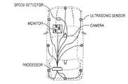
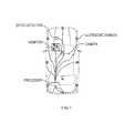
- FIG. 1is a diagram illustrating a vehicle having an ultrasonic sensor, a camera, and a speed detector according to the present invention
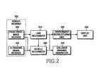
- FIG. 2is a block diagram of a driver assistance information generator of a traveling vehicle according to the present invention
- FIG. 3is a block diagram of the lane recognizer in FIG. 2 ;
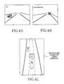
- FIGS. 4A , 4 B and 4 Care diagrams illustrating driver assistance information of a traveling vehicle according to the present invention.
- FIG. 5is a flow diagram illustrating road restructuring through recognition of lanes in front/rear of a traveling vehicle according to the present invention
- FIG. 6is a flow diagram illustrating lane recognition according to the present invention.
- FIG. 7is a screen illustrating a process for lane recognition according to the present invention.
- FIGS. 8A , 8 B and 8 Care screens obtained by restructuring lane recognition results according to the present invention.
- FIG. 9is a flow diagram illustrating a process for side-vehicle recognition according to the present invention.
- FIG. 10is a screen illustrating a side-vehicle recognition process according to the present invention.
- FIG. 11is a flow diagram illustrating a process for generating driver assistance information of a traveling vehicle based on lane and vehicle recognition according to the present invention
- FIGS. 12A , 12 B and 12 Care screens illustrating driver assistance information of a traveling vehicle generated through lane and vehicle recognition according to the present invention.
- FIG. 13is a flow diagram illustrating a process for collision warning according to the present invention.
- the present inventionprovides a method for forming a sensor system including a camera and an ultrasonic sensor for removing blind spots of a vehicle, removing the blind spots through front/rear-lane recognition, front/rear-vehicle detection, right/left-vehicle detection, and a combination of front/rear-vehicle information and right/left-vehicle information, and recognizing of environment in all directions, thereby generating a bird's eye image for watching generated road and vehicle information, and providing a warning function when danger of collision exists.
- the present inventionprovides a method for simultaneously recognizing and synthesizing the lanes by using cameras installed on a vehicle when detecting lanes in order to draw the lanes in the bird's eye image, and drawing the lanes including solid and dot lanes in the bird's eye image, so a driver can easily determine whether the driver's vehicle has deviated from a lane.
- An example of a traveling vehicleincludes a driver assistance information generator having two cameras, eight ultrasonic sensors, one monitor, a speaker, a processor, and a speed detector, as shown in FIG. 1 .
- the actual number of cameras, ultrasonic sensors, and monitors usedmay vary as desired.
- the driver assistance information generatorincludes a sensor receiver 200 having a front/rear-image receiver 202 and an ultrasonic signal receiver 204 , a lane recognizer 210 , a vehicle recognizer 230 , an environment restructuring unit 220 , and a collision warning generator 240 .
- the front/rear-image receiver 202receives images from the cameras and the ultrasonic sensors, and the ultrasonic signal receiver 204 receives ultrasonic signals.
- the lane recognizer 210recognizes lanes about the traveling vehicle, and the vehicle recognizer 230 recognizes vehicles about the traveling vehicle and obstacles about the traveling vehicle.
- the environment restructuring unit 220restructures roads and vehicles as an image, such as a three-dimensional (3D) bird's eye image, from the detected lanes and vehicles, and the collision warning generator 240 determines whether any collision has occurred among vehicles.
- 3Dthree-dimensional
- the sensor receiver 200is a means for recognizing lanes around a vehicle, and for determining whether other vehicles exist around a traveling vehicle and includes the front/rear-image receiver 202 and the ultrasonic signal receiver 204 , as described above.
- the front/rear-image receiver 202denotes a camera, which photographs images of lanes and vehicles on a road, and provides the photographed images to the lane recognizer 210 and the vehicle recognizer 230 .
- the front/rear-image receiver 202obtains an image with a size of, for example, 320 ⁇ 240 from each camera installed about the traveling vehicle to photograph circumferential environments within an angle of about 45°.
- the ultrasonic signal receiver 204denotes a sonar sensor (ultrasonic sensor), emits an ultrasonic signal within an ultrasonic range of about 10 m, and measures time until the emitted ultrasonic signal returns to the ultrasonic sensor.
- the ultrasonic signal receiver 204can compute a distance with the other vehicle based on time when the emitted ultrasonic signal is reflected from the other vehicle and is then captured by the ultrasonic sensor.
- the ultrasonic signal receiver 204includes eight ultrasonic sensors installed at various locations about the traveling vehicle to measure distances with obstacles within a range of generally a maximum 10 m around the traveling vehicle, and continues to scan each of the ultrasonic sensors.
- the lane recognizer 210removes perspective effects of a lane candidate, which is detected from an image input from the front/rear-image receiver 202 through matching with patterns of black-white-black shown in paved roads and lanes, by using inverse-perspective transform, and regenerates a lane candidate. Then, the lane recognizer 210 estimates a direction of a lane by using a slope of the lane in a short distance, recognizes the lane by approximating curvature in a long distance, and outputs an equation of the lane in a vehicle coordinate system.
- a short distanceis considered to be less than or equal to a preset distance, such as twenty meters or the like, and a long distance is considered to be greater than the preset distance.
- the lane recognizer 210will be described with reference to FIG. 3 .
- the lane recognizer 210includes a front/rear-lane recognizing unit 212 for recognizing a lane from an image input from the front/rear-image receiver 202 , a solid/dot line determining unit 214 for determining whether a detected lane is a solid lane or a dot lane, and a lane recognition synthesizing and restructuring unit 216 for synthesizing recognition results of front/rear-lanes, and restructuring the synthesis results as an image, such as a bird's eye image.
- the vehicle recognizer 230sets a road area as an area of interest by using the lane recognition results of the lane recognizer 210 , and detects a vehicle by using an image and ultrasonic signals.
- the recognition of front/rear-vehiclescan be implemented in the daytime and at night.
- the vehicle recognizer 230detects a vehicle candidate by using a shadow pattern occurring between a vehicle and a road, and recognizes a vehicle by utilizing right/left edge components of the vehicle and preliminary knowledge about the width of the vehicle.
- the vehicle recognizer 230extracts and recognizes an image through the headlights and taillights of a vehicle.
- the vehicle recognizer 230detects right/left-side vehicles by using a distance obtained from three ultrasonic sensors, determines the traveling tendency of a vehicle by using changes in the distance, and outputs the position of the vehicle in a vehicle coordinate system.
- the environment restructuring unit 220determines a solid line or a dot line of a lane by synthesizing a lane equation representing the lane and a position of a vehicle.
- the environment restructuring unit 220regards the lane as the edge of a road to which lanes have not been added any more.
- the environment restructuring unit 220adds one lane and then sets the number of lanes.
- the environment restructuring unit 220generates a road model by quantizing the shape of the road according to the curvature variation of the road.
- the environment restructuring unit 220arranges vehicles on the lanes of the generated road, and forms an image, such as a 3D road image, in which a driver can easily adjust a field of vision. Then, the environment restructuring unit 220 causes the road image to be displayed on a screen through a display unit 250 . The vehicles and road images formed through the environment restructuring unit 220 can be displayed on the screen, as shown in FIG. 4C .
- FIG. 4Ashows an image photographed by a front camera
- FIG. 4Bshows an image photographed by a rear camera.
- the collision warning generator 240estimates a Time To Collision (TTC) between vehicles by using the distance and relative speed of front/rear vehicles traveling in a lane of a traveling vehicle. After a collision time area is classified as a warning area and a danger area, a collision warning is generated.
- TTCTime To Collision
- the environment restructuring unit 220 of the driver assistance information generatorrestructures the lanes recognized by the lane recognizer 210 , and the adjacent vehicles recognized by the vehicle recognizer 230 as an image, such as a bird's eye image, of a road.
- a process by which the driver assistance information generator performs lane recognition through the lane recognizer 210will be described with reference to FIGS. 5 to 8C
- a process by which the driver assistance information generator obtains information (i.e. side-vehicle recognition and traveling information) about the adjacent vehicles recognized by the vehicle recognizer 230will be described with reference to FIG. 9 .
- a process for restructuring the recognized lanes and vehicles to generate driver assistance information of a traveling vehiclewill be described with reference to FIG. 11 .
- a process by which the lane recognizer 210 performs recognition of front/rear lanes of a traveling vehicle, and the environment restructuring unit 220 restructures a roadwill be described with reference to FIG. 5 .
- the lane recognizer 210receives front/rear-images from the front/rear-image receiver 202 .
- the lane recognizer 210recognizes a lane from the received images. An operation for recognizing a lane from the images input from the front/rear-image receiver 202 through step 502 will be described with reference to FIG. 6 .
- the lane recognizer 210extracts lane candidates according to changes in the brightness of the images in step 602 .
- the lane recognizer 210generates a histogram of the extracted lane candidates in step 604 , and determines the position of a lane adjacent to a traveling vehicle in step 606 .
- the prior artcomputes the slope of a lane based on lane images.
- the slope of the laneis not necessary.
- the lane recognizer 210computes the curvature of the lane candidates located in a long distance.
- the lane recognizer 210may also compute the curvature of the lane candidates located in a short distance when desired.
- step 610the lane recognizer 210 recognizes a long distance lane by using the curvature computed in step 608 .
- the prior artcomputes a curvature of the lane based on a slope of the lane, but the present invention actually computes a curvature to apply the computed curvature to lane recognition.
- the lane recognizer 210determines whether the detected lane is a solid line or a dot line.
- the lane recognizer 210synthesizes the recognition results of front/rear-vehicles and restructures the synthesized results as an image, such as a bird's eye image.
- the lane recognizer 210displays the image restructured in step 506 on a screen.
- the lane recognizer 210determines a solid line and a dot line from an input image by using the fact that only bright parts consecutively appear for a solid line, but dark parts and bright parts periodically appear for a dot line.
- Ran area in which a lane obtained through lane-searching results is located
- L ian area in which a lane is actually drawn
- the solid line or dot line of the obtained laneis determined by computing the ratio of the areas R and L i .
- the laneis drawn in the form of a dot line, dark parts and bright parts periodically appear in the area R.
- a ratio of the areas R and L iis calculated to determine a Solid Rate value, as shown in Equation (1).
- the laneis a solid line when the Solid Rate value is greater than a threshold.
- the laneis a dot line when the Solid Rate value is less than or equal to the threshold.
- the solid line or the dot line of the laneis determined by using the brightness of the lane through Equation (1), so the type of a lane can be abnormally determined depending on road and adjacent brightness.
- the type of a laneis determined based on a lane obtained from the front-image of the images input from the front/rear-image receiver 202
- the type of a laneis determined based on a lane obtained from the rear-image of the images input from the front/rear-image receiver 202 .
- the type of the laneis determined based on the three following criteria.
- the type of a laneis modified in the restructuring of a road.
- the present inventionuses a road model. That is, a general road model is generated in advance, and the prepared road model is compared with a lane obtained through an input image. Then, a road model having a value most approximate to that of the lane obtained from the image is used for restructuring a lane.
- the lanes of a road in a long distancemay be distorted due to an error. Accordingly, when recognized results are reflected without changes, a curvature changes momentarily and considerably, and thus a road curved in a right direction may be suddenly altered into a road curved in a left direction, which results in unnatural alteration. That is, when a lane recognized in a current frame changes more than a threshold value due to an error or the rapid alteration of a road in a lane recognition process, as compared to a lane obtained in a previous frame, when this is reflected to a road model to restructure the road, the restructured road may change suddenly and considerably, which results in driver confusion.
- a neighbor model most approximate to the road model, having been used for the road restructuringis used for subsequent road restructuring regardless of the variation as, expressed by Equation (5), so it is possible to minimize an error of road restructuring which may be caused by abnormal lane recognition.
- a lane curvature R obtained from an imagechanges from ⁇ 0.00125 to 0.00125
- a lane curvature increasing step-by-stepfrom ⁇ 0.00125 to ⁇ 0.00115, . . .
- Equation (6)When parameter A to be used for road restructuring is determined through Equation (4) above, the right and left lanes to be used for the road restructuring are determined through Equation (6) above.
- the lane to be used for the road restructuringis a dot lane, another lane exists adjacent to a lane along which a traveling vehicle is traveling. Accordingly, when FL(Y) in Equation (6) is a dot lane, FLL(Y) is additionally generated in the form of solid lane as expressed by Equation (7). Further, when FR(Y) in Equation (6) is a dot lane, FRR(Y) is additionally generated in the form of solid lane, as expressed by Equation (7), so a road can be restructured similarly to road environments in which the traveling vehicle is traveling.
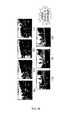
- FIGS. 8A-Cshow a front-image input from the front/rear-image receiver 202
- FIG. 8Bshows a rear-image input from the front/rear-image receiver 202 .
- the lane recognizer 210detects lanes from the front-image and rear-image, as shown in FIGS. 5 and 6 , and can display the restructured image, such as an image in the form of a 3D bird's eye view, based on the traveling vehicle 800 .
- a process for obtaining recognition and travel information about adjacent vehicles (side-vehicles) recognized through the vehicle recognizer 230 , and a process for generating driver assistance information of a traveling vehicle by restructuring the recognized lanes and vehicleswill be described with reference to FIG. 11 .
- a road areais set as an area of interest by using the lane recognition results of the lane recognizer 210 , and a vehicle is detected by using an image and ultrasonic signals.
- the recognition of front/rear-vehiclescan be implemented in the daytime and at night.
- a vehicle candidateis detected by using a shadow pattern occurring between a vehicle and a road, and a vehicle is recognized by utilizing right/left edge components of the vehicle and preliminary knowledge about the width of the vehicle.
- an imageis extracted and recognized through the headlights and taillights of a vehicle.
- right/left-side vehiclesare detected by using a distance obtained from three ultrasonic sensors, and the traveling tendency of a vehicle is determined by using changes in the distance.
- ultrasonic signalsare received from three sonars, i.e. ultrasonic sensors, installed on the right side of the vehicle, and three ultrasonic sensors installed on the left side of the vehicle, as shown in FIG. 1 . That is, the ultrasonic signal receiver 204 of FIG. 2 receives the ultrasonic signals. Then, the ultrasonic signal receiver 204 outputs the received ultrasonic signals to the vehicle recognizer 230 . In step 902 , the vehicle recognizer 230 detects a vehicle by using distance information obtained from the ultrasonic signals.
- the vehicle recognizer 230determines the traveling tendency of a vehicle traveling in a side lane by judging whether ultrasonic waves have been detected_according to the passage of time in step 906 .
- the ultrasonic signals output from the three ultrasonic sensors installed at the side of the vehicleare expressed by a bitstream including 0 and 1, as expressed by Equation (8).
- the bitstreamis set to 1. Otherwise, the bitstream has a value of 0.
- b[s 1 s 2 s 3 ], s i ⁇ [0, 1] (8)
- the vehicle recognizer 230determines the traveling tendency of a vehicle in step 906 , and performs vehicle detection in cooperation with a front/rear-recognizer.
- a vehicle of a corresponding laneis detected through a rear-vehicle recognition.
- a vehicleis detected through a front-vehicle recognition.
- a vehicle candidateis generated until the vehicle is detected on an assumption that the vehicle exists in blind spots.
- a vehicle detected by a front or rear-vehicle recognizergradually disappears from right/left areas, a vehicle candidate is generated until the vehicle is detected by a side-vehicle recognizer because the vehicle exists in right/left short distance areas.
- the environment restructuring unit 220determines whether a lane is a solid lane or a dot lane through a lane recognition process as shown in FIGS. 5 and 6 , and estimates a road model. In order to arrange vehicles in a newly set road model in step 14 , the environment restructuring unit 220 applies a position relation between a previous lane and a vehicle to a new road model, and arranges vehicles detected through the front/rear-vehicle detection process and the side-vehicle detection process, as shown in FIG. 9 .
- the environment restructuring unit 220displays a longitudinal direction distance by using Open Graphics Language (OpenGL) for a front/rear-vehicle, and a lateral direction distance by using OpenGL for a right/left-vehicle. Further, the environment restructuring unit 220 differently expresses the color of a vehicle model in each lane, and restructures a 3D image in which a driver can easily adjust a field of vision.
- the arrangement example of the restructured road and vehiclesmay be as shown in FIGS. 12A-C .
- FIG. 12Cshows an example of the road and vehicles restructured through the front-image of FIG. 12A and the rear-image of FIG. 12B in a situation in which a traveling vehicle is traveling in a two-lane one way.
- an inter-vehicle distanceuses an average distance of five consecutive times in order to reduce an error of inverse-perspective transform.
- the collision warning generator 240estimates a relative speed by using a time difference among obtained images and a distance difference with a previous image.
- An inter-vehicle relative speed vmay be computed from a difference between an inter-vehicle distance d t ⁇ 1 in a previous frame and an inter-vehicle distance d t in a current frame, and a time difference ⁇ t among obtained images, as expressed by Equation (9).
- step 32the collision warning generator 240 estimates a TTC between a traveling vehicle and a detected vehicle from a current distance and a relative speed, as expressed by Equation (10).
- the collision warning generator 240warns a TTC for the traveling vehicle according to a warning area and a danger area in a particular manner.
- the warning areais set as an area in which a vehicle is traveling within a breaking distance. In the warning area, it is possible to set in advance the output of a voice message for attracting attention.
- the danger areais set as an area in which a vehicle is traveling within a TTC of a ⁇ 2 to 0 sec, and it is possible to set the output of a consecutive warning sound.
- the present inventioncan restructure traveling environments into a bird's eye image based on a sensor system capable of removing blind spots around a traveling vehicle, and a method capable of exactly detecting a lane and a vehicle, and give a collision warning when there is a possibility of collision. Accordingly, since a driver can easily become aware of information about blind spots, the driver can operate with reduced anxiety for blind spots, and can drive a vehicle conveniently and safely through detection of position and relative speed of an adjacent vehicle, and collision warning.
- the present inventionintegrates recognition results of front/rear vehicles based on a lane recognition method applicable to various road environments including shape, curvature, loss of a lane, etc., improves stability of lane recognition, and distinguishes a solid line from a dot line, so it is possible to provide a driver with varying degrees of danger.
- a voice warningmay be output and a position of the vehicle for a road is restructured as a bird's eye image, so it is possible to improve stability and convenience because a driver can become aware of the vehicle status at a glance.
Landscapes
- Engineering & Computer Science (AREA)
- Radar, Positioning & Navigation (AREA)
- Remote Sensing (AREA)
- Multimedia (AREA)
- Physics & Mathematics (AREA)
- General Physics & Mathematics (AREA)
- Mechanical Engineering (AREA)
- Computer Networks & Wireless Communication (AREA)
- Acoustics & Sound (AREA)
- Theoretical Computer Science (AREA)
- Automation & Control Theory (AREA)
- Human Computer Interaction (AREA)
- Transportation (AREA)
- Traffic Control Systems (AREA)
- Image Processing (AREA)
Abstract
Description
f(y)=ax2+bx+c (2)
ifa>R(i−1) anda<R(i)
Bn1=R(i−1),Bn2=R(i) (3)
A=(Bn1+Bn2)/2 (4)
if (a<Bn1)
Bn1=R(i−2),Bn2=R(i−1)
else if (a>Bn2)
Bn1=R(i),Bn2=R(i+1) (5)
FL(Y)=AX2+0·X−1.7
FR(Y)=AX2+0·X+1.7 (6)
if left lane is a dot lane
FLL(Y)=AX2+0·X−3.4
if right lane is a dot lane
FRR(Y)=AX2+0·X+3.4 (7)
b=[s1s2s3], si∈ [0, 1] (8)
Claims (12)
Applications Claiming Priority (3)
| Application Number | Priority Date | Filing Date | Title |
|---|---|---|---|
| KR10-2006-0063649 | 2006-07-06 | ||
| KR1020060063649AKR101075615B1 (en) | 2006-07-06 | 2006-07-06 | Apparatus and method for generating a auxiliary information of moving vehicles for driver |
| KR2006-63649 | 2006-07-06 |
Publications (2)
| Publication Number | Publication Date |
|---|---|
| US20080055114A1 US20080055114A1 (en) | 2008-03-06 |
| US7710291B2true US7710291B2 (en) | 2010-05-04 |
Family
ID=39035701
Family Applications (1)
| Application Number | Title | Priority Date | Filing Date |
|---|---|---|---|
| US11/774,253Active2028-04-21US7710291B2 (en) | 2006-07-06 | 2007-07-06 | Apparatus and method for generating driver assistance information of traveling vehicle |
Country Status (4)
| Country | Link |
|---|---|
| US (1) | US7710291B2 (en) |
| EP (1) | EP1918897A3 (en) |
| KR (1) | KR101075615B1 (en) |
| CN (1) | CN101101333A (en) |
Cited By (6)
| Publication number | Priority date | Publication date | Assignee | Title |
|---|---|---|---|---|
| US20080215235A1 (en)* | 2006-10-09 | 2008-09-04 | Marek Strassenburg-Kleciak | Selection and insertion of static elements in digital maps |
| US20090037039A1 (en)* | 2007-08-01 | 2009-02-05 | General Electric Company | Method for locomotive navigation and track identification using video |
| US20110046882A1 (en)* | 2008-02-04 | 2011-02-24 | Thomas Heger | Device and method for determining the position of another road user |
| US20150183430A1 (en)* | 2013-09-05 | 2015-07-02 | Robert Bosch Gmbh | Enhanced lane departure system |
| US10949886B2 (en)* | 2019-03-12 | 2021-03-16 | Xevo Inc. | System and method for providing content to a user based on a predicted route identified from audio or images |
| US20220018658A1 (en)* | 2018-12-12 | 2022-01-20 | The University Of Tokyo | Measuring system, measuring method, and measuring program |
Families Citing this family (111)
| Publication number | Priority date | Publication date | Assignee | Title |
|---|---|---|---|---|
| US20090224897A1 (en)* | 2008-03-04 | 2009-09-10 | Tien-Bou Wan | Vehicle vision system |
| DE112009001440B4 (en)* | 2008-06-11 | 2014-01-09 | Mitsubishi Electric Corp. | Navigation device and map data processing method |
| EP2319031A4 (en)* | 2008-07-01 | 2014-01-08 | Kpit Technologies Ltd | Sensor system for vehicle safety |
| JP5304128B2 (en)* | 2008-09-16 | 2013-10-02 | 村田機械株式会社 | Environmental map correction device and autonomous mobile device |
| JP5094658B2 (en)* | 2008-09-19 | 2012-12-12 | 日立オートモティブシステムズ株式会社 | Driving environment recognition device |
| JP2010183170A (en)* | 2009-02-03 | 2010-08-19 | Denso Corp | Display apparatus for vehicle |
| DE102009007342A1 (en)* | 2009-02-04 | 2010-08-05 | Hella Kgaa Hueck & Co. | Method and device for determining an applicable lane marking |
| US8384532B2 (en)* | 2009-04-02 | 2013-02-26 | GM Global Technology Operations LLC | Lane of travel on windshield head-up display |
| KR100956858B1 (en)* | 2009-05-19 | 2010-05-11 | 주식회사 이미지넥스트 | Sensing method and apparatus of lane departure using vehicle around image |
| DE102009028774A1 (en)* | 2009-08-21 | 2011-02-24 | Robert Bosch Gmbh | Method and control unit for robust recognition of a lane change of a vehicle |
| JP5453048B2 (en)* | 2009-10-22 | 2014-03-26 | 富士重工業株式会社 | Vehicle driving support control device |
| US20120022739A1 (en)* | 2010-07-20 | 2012-01-26 | Gm Global Technology Operations, Inc. | Robust vehicular lateral control with front and rear cameras |
| US8447437B2 (en)* | 2010-11-22 | 2013-05-21 | Yan-Hong Chiang | Assistant driving system with video recognition |
| EP2993654B1 (en)* | 2010-12-07 | 2017-05-03 | Mobileye Vision Technologies Ltd. | Method and system for forward collision warning |
| EP2484566A1 (en) | 2011-02-08 | 2012-08-08 | Volvo Car Corporation | Brake assist system |
| DE102011018157A1 (en)* | 2011-04-19 | 2012-10-25 | GM Global Technology Operations LLC (n. d. Gesetzen des Staates Delaware) | Detection of a bus stop |
| JP6193222B2 (en) | 2011-06-17 | 2017-09-06 | ローベルト ボッシュ ゲゼルシャフト ミット ベシュレンクテル ハフツング | Program for realizing a function for assisting a driver when a vehicle is guided on a roadway, and an apparatus for executing the program |
| DE102011084762A1 (en)* | 2011-10-19 | 2013-04-25 | Robert Bosch Gmbh | Method and device for determining a position of an object in an environment of a vehicle |
| DE102012200731A1 (en)* | 2012-01-19 | 2013-07-25 | Robert Bosch Gmbh | Method and device for visualizing the environment of a vehicle |
| JP5543501B2 (en)* | 2012-01-27 | 2014-07-09 | 株式会社日本自動車部品総合研究所 | Vehicle control device |
| CN102663356B (en)* | 2012-03-28 | 2015-04-08 | 柳州博实唯汽车科技有限公司 | Method for extraction and deviation warning of lane line |
| US9591274B2 (en)* | 2012-07-27 | 2017-03-07 | Nissan Motor Co., Ltd. | Three-dimensional object detection device, and three-dimensional object detection method |
| KR101927155B1 (en)* | 2012-10-19 | 2018-12-10 | 현대자동차 주식회사 | Method and system for recognizing space of shoulder of road |
| US9165196B2 (en) | 2012-11-16 | 2015-10-20 | Intel Corporation | Augmenting ADAS features of a vehicle with image processing support in on-board vehicle platform |
| WO2014083826A1 (en)* | 2012-11-27 | 2014-06-05 | 日産自動車株式会社 | Acceleration suppression device for vehicle, and acceleration suppression method for vehicle |
| CN103065501B (en)* | 2012-12-14 | 2014-08-06 | 清华大学 | Automobile lane changing early-warning method and lane changing early-warning system |
| CN103050011B (en)* | 2012-12-15 | 2014-10-22 | 浙江交通职业技术学院 | Driveway information indicating system |
| CN104050829A (en)* | 2013-03-14 | 2014-09-17 | 联想(北京)有限公司 | Information processing method and apparatus |
| US20140277833A1 (en)* | 2013-03-15 | 2014-09-18 | Mighty Carma, Inc. | Event triggered trip data recorder |
| US10171775B1 (en)* | 2013-05-31 | 2019-01-01 | Vecna Technologies, Inc. | Autonomous vehicle vision system |
| KR101782496B1 (en)* | 2013-08-21 | 2017-09-27 | 주식회사 만도 | Back-sideways alarming system of vehicle and alarming control method of the same |
| JP2015067193A (en)* | 2013-09-30 | 2015-04-13 | 株式会社デンソー | Preceding vehicle selection device |
| RU2624392C1 (en)* | 2013-10-11 | 2017-07-03 | Ниссан Мотор Ко., Лтд. | Mobile management device and method for traffic control |
| KR101510336B1 (en)* | 2013-11-14 | 2015-04-07 | 현대자동차 주식회사 | Device for inspecting driver assistance system of vehicle |
| JP2015096377A (en)* | 2013-11-15 | 2015-05-21 | 株式会社デンソー | Lane deviation warning device |
| KR101510338B1 (en)* | 2013-11-22 | 2015-04-07 | 현대자동차 주식회사 | Device for inspecting lane departure warning system of vehicle |
| KR101582572B1 (en)* | 2013-12-24 | 2016-01-11 | 엘지전자 주식회사 | Driver assistance apparatus and Vehicle including the same |
| KR102158745B1 (en)* | 2014-03-18 | 2020-09-22 | 한국전자통신연구원 | Device for correcting the obstacle detection on the curve road and method thereof |
| CN104952254B (en)* | 2014-03-31 | 2018-01-23 | 比亚迪股份有限公司 | Vehicle identification method, device and vehicle |
| JP6126043B2 (en)* | 2014-04-25 | 2017-05-10 | 本田技研工業株式会社 | Road departure prevention support device and road departure prevention support method |
| CN103950410A (en)* | 2014-04-29 | 2014-07-30 | 深圳前向启创数码技术有限公司 | Panoramic auxiliary driving method and system |
| CN104015657B (en)* | 2014-06-16 | 2016-09-14 | 国通道路交通管理工程技术研究中心有限公司 | The illegal method and system overtaken other vehicles of a kind of key preventive haulage vehicle |
| WO2015194371A1 (en)* | 2014-06-19 | 2015-12-23 | 日立オートモティブシステムズ株式会社 | Object recognition apparatus and vehicle travel controller using same |
| US10377303B2 (en)* | 2014-09-04 | 2019-08-13 | Toyota Motor Engineering & Manufacturing North America, Inc. | Management of driver and vehicle modes for semi-autonomous driving systems |
| DE102015117535A1 (en) | 2014-10-17 | 2016-04-21 | Hyundai Mobis Co., Ltd. | Device and method for driver assistance |
| KR101603618B1 (en)* | 2014-11-12 | 2016-03-28 | 현대모비스 주식회사 | System and method for recognizing surrounding vehicle |
| KR102270578B1 (en)* | 2014-11-18 | 2021-06-29 | 현대모비스 주식회사 | Apparatus and method for controlling displaying forward information of vehicle |
| KR101617345B1 (en)* | 2014-12-03 | 2016-05-02 | 현대모비스 주식회사 | System and method for estimating driving lane of vehicle |
| CN105761536B (en)* | 2014-12-17 | 2019-12-10 | 宇龙计算机通信科技(深圳)有限公司 | Driving assistance method and device |
| KR101645717B1 (en)* | 2015-01-28 | 2016-08-12 | (주)한양정보통신 | Apparatus and method for adaptive calibration of advanced driver assistance system |
| DE102015201723A1 (en)* | 2015-02-02 | 2016-08-04 | Robert Bosch Gmbh | Driver assistance system for a motor vehicle |
| US9714033B2 (en)* | 2015-02-08 | 2017-07-25 | AI Incorporated | Vehicle collision avoidance system |
| JP6408935B2 (en)* | 2015-03-04 | 2018-10-17 | 株式会社Soken | Traveling line recognition device |
| JP6451464B2 (en)* | 2015-04-02 | 2019-01-16 | 株式会社デンソー | Collision avoidance device and collision avoidance system |
| CN107533803B (en) | 2015-04-23 | 2019-03-12 | 日产自动车株式会社 | Block control device |
| CN104859563B (en)* | 2015-05-28 | 2017-07-04 | 北京汽车股份有限公司 | lane departure warning method and system |
| KR102278387B1 (en)* | 2015-07-07 | 2021-07-16 | 주식회사 만도 | Distance calculating apparatus and distance calculating method and driving assist apparatus and driving assist system |
| KR102355321B1 (en)* | 2015-09-10 | 2022-01-25 | 주식회사 만도모빌리티솔루션즈 | Lane keeping assistance system and method for assisting keeping lane of the same |
| US9771071B2 (en)* | 2015-11-19 | 2017-09-26 | Ford Global Technologies, Llc | Dynamic lane positioning for improved biker safety |
| CN105472193B (en)* | 2015-11-25 | 2018-08-31 | 东莞市智捷自动化设备有限公司 | Vehicle-mounted safety information automatic opening method based on intelligent terminal |
| CN105336217A (en)* | 2015-12-09 | 2016-02-17 | 东华大学 | Driving safety prewarning system based on machine vision and Android platform |
| WO2017128193A1 (en)* | 2016-01-28 | 2017-08-03 | 郭子明 | Method and device for pushing information during lane departure warning |
| WO2017128194A1 (en)* | 2016-01-28 | 2017-08-03 | 郭子明 | Lane departure warning method and device |
| JP6752024B2 (en)* | 2016-02-12 | 2020-09-09 | 日立オートモティブシステムズ株式会社 | Image processing device |
| JP6583121B2 (en)* | 2016-04-21 | 2019-10-02 | 株式会社デンソー | Driving assistance device |
| DE102016210632A1 (en)* | 2016-06-15 | 2017-12-21 | Bayerische Motoren Werke Aktiengesellschaft | Method for checking a media loss of a motor vehicle and motor vehicle and system for carrying out such a method |
| GB2552487B (en)* | 2016-07-25 | 2019-03-20 | Ford Global Tech Llc | Flow corridor detection and display system |
| WO2018051906A1 (en)* | 2016-09-15 | 2018-03-22 | 株式会社小糸製作所 | Sensor system, sensor module, and lamp device |
| JP6615725B2 (en)* | 2016-09-16 | 2019-12-04 | 株式会社東芝 | Travel speed calculation device and travel speed calculation method |
| US9928426B1 (en)* | 2016-09-16 | 2018-03-27 | Hong Kong Applied Science and Technology Research Institute Company Limited | Vehicle detection, tracking and localization based on enhanced anti-perspective transformation |
| EP3778305B1 (en) | 2016-11-01 | 2022-03-30 | Panasonic Intellectual Property Corporation of America | Display method and display device |
| KR102749979B1 (en)* | 2016-11-09 | 2025-01-03 | 삼성전자주식회사 | Generating method and apparatus of virtual driving lane for driving car |
| JP6466899B2 (en)* | 2016-12-01 | 2019-02-06 | 株式会社Subaru | Vehicle display device |
| KR102471072B1 (en)* | 2016-12-21 | 2022-11-25 | 삼성전자주식회사 | Electronic apparatus and operating method for the same |
| KR102278347B1 (en)* | 2017-02-24 | 2021-07-19 | 현대자동차주식회사 | Apparatus and method for warning generation of vehicle |
| CN106926779B (en)* | 2017-03-09 | 2019-10-29 | 吉利汽车研究院(宁波)有限公司 | A kind of vehicle lane change auxiliary system |
| JP6894744B2 (en)* | 2017-03-31 | 2021-06-30 | 株式会社Subaru | Image display device |
| EP3631675B1 (en)* | 2017-06-28 | 2023-09-13 | Huawei Technologies Co., Ltd. | Advanced driver assistance system and method |
| CN113119963B (en)* | 2017-07-28 | 2024-03-26 | 现代摩比斯株式会社 | Intelligent ultrasonic system, vehicle rear collision warning device and control method thereof |
| CN109427199B (en)* | 2017-08-24 | 2022-11-18 | 北京三星通信技术研究有限公司 | Augmented reality method and device for assisted driving |
| JP6666883B2 (en)* | 2017-09-01 | 2020-03-18 | 株式会社Subaru | Driving support device |
| JP6744269B2 (en) | 2017-09-06 | 2020-08-19 | 本田技研工業株式会社 | Driving support device and driving support method |
| KR101962701B1 (en)* | 2017-09-25 | 2019-03-27 | 주식회사 만도 | Method and Apparatus of vehicle alarm that alarm area is changed by visible distance |
| KR102374919B1 (en)* | 2017-10-16 | 2022-03-16 | 주식회사 만도모빌리티솔루션즈 | Device And Method of Automatic Driving Support |
| KR102428660B1 (en)* | 2017-11-08 | 2022-08-03 | 현대자동차주식회사 | Vehicle and control method for the same |
| CN107839611A (en)* | 2017-11-15 | 2018-03-27 | 福建捷联电子有限公司 | Electronics rearview mirror with drive assist system warning |
| CN108090456B (en)* | 2017-12-27 | 2020-06-19 | 北京初速度科技有限公司 | Training method for recognizing lane line model, and lane line recognition method and device |
| CN108482246A (en)* | 2018-02-08 | 2018-09-04 | 深圳市赛格导航科技股份有限公司 | A kind of vehicle carried driving householder method, device, equipment and storage medium |
| CN108509906B (en)* | 2018-03-30 | 2022-02-08 | 长安大学 | Double-threshold Radon identification method for line light point capture of unmanned aerial vehicle aerial photography roadbed |
| US20210166563A1 (en)* | 2018-06-18 | 2021-06-03 | Ask Industries Gmbh | Motor vehicle, comprising an apparatus for outputting an audio signal to a passenger compartment of the motor vehicle |
| KR102483649B1 (en)* | 2018-10-16 | 2023-01-02 | 삼성전자주식회사 | Vehicle localization method and vehicle localization apparatus |
| CN111352072B (en)* | 2018-12-24 | 2023-09-26 | 观致汽车有限公司 | Blind area detection device and method for vehicle |
| CN111409553B (en)* | 2019-01-08 | 2024-02-20 | 上汽通用五菱汽车股份有限公司 | ADAS display device and method |
| KR102681062B1 (en)* | 2019-01-28 | 2024-07-05 | 주식회사 에이치엘클레무브 | Apparatus, system and method for preventing collision |
| CN109895699A (en)* | 2019-03-11 | 2019-06-18 | 汉腾汽车有限公司 | A kind of system and method indicating Vehicle target and degree of danger |
| CN110133663B (en)* | 2019-05-08 | 2023-03-10 | 西安联丰迅声信息科技有限责任公司 | Distributed acoustic image joint calibration positioning method |
| CN112817303B (en)* | 2019-11-18 | 2024-04-30 | 富联精密电子(天津)有限公司 | Self-propelled triangular warning frame and travelling control method thereof |
| US11702140B2 (en)* | 2019-11-19 | 2023-07-18 | Robert Bosch Gmbh | Vehicle front optical object detection via photoelectric effect of metallic striping |
| CN110843673B (en)* | 2019-11-20 | 2021-05-18 | 斑马网络技术有限公司 | Vehicle-mounted anti-vertigo view forming method, generating device and anti-vertigo device |
| DE102020216470A1 (en)* | 2019-12-26 | 2021-07-01 | Mando Corporation | DRIVER ASSISTANCE SYSTEM, VEHICLE EQUIPPED WITH IT AND METHOD FOR CONTROLLING THE VEHICLE |
| CN111845560B (en)* | 2020-03-31 | 2022-09-20 | 同济大学 | A warning system for a vehicle head overrunning an object |
| KR20210130302A (en)* | 2020-04-21 | 2021-11-01 | 주식회사 만도모빌리티솔루션즈 | Driver assistance system and the conrol method of the same |
| CN112185111A (en)* | 2020-09-21 | 2021-01-05 | 成都三维大川新材料科技有限公司 | Urban traffic intelligent management and control system and method based on power line carrier |
| CN112669578B (en)* | 2020-12-18 | 2022-04-19 | 上海影创信息科技有限公司 | Interested object warning method and system based on sound source in afterglow area |
| EP4068153A1 (en)* | 2021-03-31 | 2022-10-05 | Honda Research Institute Europe GmbH | Advanced driver assistance system for assisting a driver of a vehicle |
| DE102021206880B4 (en)* | 2021-06-30 | 2025-05-08 | Robert Bosch Gesellschaft mit beschränkter Haftung | Method and device for the optimal parameterization of a vehicle dynamics control system |
| CN113297685B (en)* | 2021-07-27 | 2021-11-02 | 中汽研(天津)汽车工程研究院有限公司 | A kind of vehicle operating condition pattern recognition method |
| CN114056337B (en)* | 2021-10-29 | 2023-12-29 | 阿里巴巴新加坡控股有限公司 | Method, device and computer program product for predicting vehicle running behavior |
| KR102753498B1 (en) | 2022-02-21 | 2025-01-10 | 김태현 | Forward driving information displaying apparatus for vehicle |
| KR102448944B1 (en)* | 2022-07-29 | 2022-09-30 | 시티아이랩 주식회사 | A speed measuring method and speed measuring device for measuring the speed of a vehicle object by correcting the perspective distortion of the image |
| CN116977968B (en)* | 2023-08-10 | 2024-11-08 | 河北海康博实科技有限公司 | Vehicle-mounted camera-based roadway identification system, method and storage medium |
Citations (12)
| Publication number | Priority date | Publication date | Assignee | Title |
|---|---|---|---|---|
| US5699057A (en)* | 1995-06-16 | 1997-12-16 | Fuji Jukogyo Kabushiki Kaisha | Warning system for vehicle |
| US6107939A (en)* | 1998-11-05 | 2000-08-22 | Trimble Navigation Limited | Lane change alarm for use in a highway vehicle |
| EP1065642A2 (en) | 1999-06-25 | 2001-01-03 | Fujitsu Ten Limited | Vehicle drive assist system |
| US6191704B1 (en) | 1996-12-19 | 2001-02-20 | Hitachi, Ltd, | Run environment recognizing apparatus |
| US6324450B1 (en)* | 1999-10-08 | 2001-11-27 | Clarion Co., Ltd | Mobile object information recording apparatus |
| US20020031242A1 (en) | 1996-08-28 | 2002-03-14 | Nobuhiko Yasui | Local positioning appartus, and method therefor |
| US6388565B1 (en)* | 1999-05-08 | 2002-05-14 | Daimlerchrysler Ag | Guidance system for assisting lane change of a motor vehicle |
| US20030025597A1 (en) | 2001-07-31 | 2003-02-06 | Kenneth Schofield | Automotive lane change aid |
| US20030154021A1 (en)* | 2000-08-24 | 2003-08-14 | Thomas Delling | Method for obtaining a map representation, and a navigation device |
| US20040012488A1 (en) | 2002-04-25 | 2004-01-22 | Kenneth Schofield | Driving separation distance indicator |
| US7403219B2 (en)* | 2004-05-11 | 2008-07-22 | Toyota Jidosha Kabushiki Kaisha | Driving lane recognizer and driving lane recognizing method |
| US7409279B2 (en)* | 2003-10-29 | 2008-08-05 | Nissan Motor Co., Ltd. | Lane departure prevention apparatus |
- 2006
- 2006-07-06KRKR1020060063649Apatent/KR101075615B1/ennot_activeExpired - Fee Related
- 2007
- 2007-07-06EPEP20070111911patent/EP1918897A3/ennot_activeWithdrawn
- 2007-07-06USUS11/774,253patent/US7710291B2/enactiveActive
- 2007-07-06CNCNA200710128113XApatent/CN101101333A/enactivePending
Patent Citations (14)
| Publication number | Priority date | Publication date | Assignee | Title |
|---|---|---|---|---|
| US5699057A (en)* | 1995-06-16 | 1997-12-16 | Fuji Jukogyo Kabushiki Kaisha | Warning system for vehicle |
| US20020031242A1 (en) | 1996-08-28 | 2002-03-14 | Nobuhiko Yasui | Local positioning appartus, and method therefor |
| US6191704B1 (en) | 1996-12-19 | 2001-02-20 | Hitachi, Ltd, | Run environment recognizing apparatus |
| US6107939A (en)* | 1998-11-05 | 2000-08-22 | Trimble Navigation Limited | Lane change alarm for use in a highway vehicle |
| US6388565B1 (en)* | 1999-05-08 | 2002-05-14 | Daimlerchrysler Ag | Guidance system for assisting lane change of a motor vehicle |
| EP1065642A2 (en) | 1999-06-25 | 2001-01-03 | Fujitsu Ten Limited | Vehicle drive assist system |
| US6324450B1 (en)* | 1999-10-08 | 2001-11-27 | Clarion Co., Ltd | Mobile object information recording apparatus |
| US20030154021A1 (en)* | 2000-08-24 | 2003-08-14 | Thomas Delling | Method for obtaining a map representation, and a navigation device |
| US20030025597A1 (en) | 2001-07-31 | 2003-02-06 | Kenneth Schofield | Automotive lane change aid |
| US6882287B2 (en)* | 2001-07-31 | 2005-04-19 | Donnelly Corporation | Automotive lane change aid |
| US7355524B2 (en)* | 2001-07-31 | 2008-04-08 | Donnelly Corporation | Automotive lane change aid |
| US20040012488A1 (en) | 2002-04-25 | 2004-01-22 | Kenneth Schofield | Driving separation distance indicator |
| US7409279B2 (en)* | 2003-10-29 | 2008-08-05 | Nissan Motor Co., Ltd. | Lane departure prevention apparatus |
| US7403219B2 (en)* | 2004-05-11 | 2008-07-22 | Toyota Jidosha Kabushiki Kaisha | Driving lane recognizer and driving lane recognizing method |
Cited By (9)
| Publication number | Priority date | Publication date | Assignee | Title |
|---|---|---|---|---|
| US20080215235A1 (en)* | 2006-10-09 | 2008-09-04 | Marek Strassenburg-Kleciak | Selection and insertion of static elements in digital maps |
| US8918274B2 (en)* | 2006-10-09 | 2014-12-23 | Harman Becker Automotive Systems Gmbh | Selection and insertion of static elements in digital maps |
| US20090037039A1 (en)* | 2007-08-01 | 2009-02-05 | General Electric Company | Method for locomotive navigation and track identification using video |
| US20110046882A1 (en)* | 2008-02-04 | 2011-02-24 | Thomas Heger | Device and method for determining the position of another road user |
| US8612150B2 (en)* | 2008-02-04 | 2013-12-17 | Robert Bosch Gmbh | Device and method for determining the position of another road user |
| US20150183430A1 (en)* | 2013-09-05 | 2015-07-02 | Robert Bosch Gmbh | Enhanced lane departure system |
| US9415776B2 (en)* | 2013-09-05 | 2016-08-16 | Robert Bosch Gmbh | Enhanced lane departure system |
| US20220018658A1 (en)* | 2018-12-12 | 2022-01-20 | The University Of Tokyo | Measuring system, measuring method, and measuring program |
| US10949886B2 (en)* | 2019-03-12 | 2021-03-16 | Xevo Inc. | System and method for providing content to a user based on a predicted route identified from audio or images |
Also Published As
| Publication number | Publication date |
|---|---|
| KR101075615B1 (en) | 2011-10-21 |
| EP1918897A3 (en) | 2008-05-14 |
| EP1918897A2 (en) | 2008-05-07 |
| KR20080004835A (en) | 2008-01-10 |
| CN101101333A (en) | 2008-01-09 |
| US20080055114A1 (en) | 2008-03-06 |
Similar Documents
| Publication | Publication Date | Title |
|---|---|---|
| US7710291B2 (en) | Apparatus and method for generating driver assistance information of traveling vehicle | |
| EP2214149B1 (en) | Collision avoidance assisting system for vehicle | |
| US6734787B2 (en) | Apparatus and method of recognizing vehicle travelling behind | |
| JP4420011B2 (en) | Object detection device | |
| JP5345350B2 (en) | Vehicle driving support device | |
| US10650256B2 (en) | Automatically perceiving travel signals | |
| JP5938569B2 (en) | Advanced driver support system considering azimuth information and operation method thereof | |
| RU2629433C2 (en) | Device for detecting three-dimensional objects | |
| US20050125121A1 (en) | Vehicle driving assisting apparatus | |
| US10643084B2 (en) | Automatically perceiving travel signals | |
| KR101103526B1 (en) | Collision Avoidance Using Stereo Camera | |
| US20070126565A1 (en) | Process for monitoring blind angle in motor vehicles | |
| KR101240499B1 (en) | Device and method for real time lane recogniton and car detection | |
| EP3530536A1 (en) | Autonomous emergency braking system and method for vehicle at crossroad | |
| JP2015506014A (en) | Method and apparatus for recognizing braking conditions | |
| EP3612424A1 (en) | Automatically perceiving travel signals | |
| JP2009252198A (en) | Travel environment presuming device, method and program, and traffic lane deviation alarm device and steering assisting apparatus | |
| JP2004310522A (en) | Image processing device for vehicles | |
| JP2006338594A (en) | Pedestrian recognition device | |
| CN112542060B (en) | Rear side alarm device for vehicle | |
| JP5688396B2 (en) | Object recognition device | |
| JP2020095380A (en) | Vehicle driving support program, vehicle driving support method, and vehicle driving support program | |
| JP2024034046A (en) | Driving support device, driving support method, and driving support program | |
| KR20170133756A (en) | System and Method for Recognizing Cut-in Vehicle on the basis of Monocular Image | |
| KR102040919B1 (en) | Blind spot detection system |
Legal Events
| Date | Code | Title | Description |
|---|---|---|---|
| AS | Assignment | Owner name:SAMSUNG ELECTRONICS CO., LTD., KOREA, REPUBLIC OF Free format text:ASSIGNMENT OF ASSIGNORS INTEREST;ASSIGNORS:KIM, KWANG-SOO;OH, SE-YOUNG;KIM, JIN-WON;AND OTHERS;REEL/FRAME:019524/0967 Effective date:20070706 Owner name:POSTECH ACADEMY INDUSTRY FOUNDATION, KOREA, REPUBL Free format text:ASSIGNMENT OF ASSIGNORS INTEREST;ASSIGNORS:KIM, KWANG-SOO;OH, SE-YOUNG;KIM, JIN-WON;AND OTHERS;REEL/FRAME:019524/0967 Effective date:20070706 Owner name:SAMSUNG ELECTRONICS CO., LTD.,KOREA, REPUBLIC OF Free format text:ASSIGNMENT OF ASSIGNORS INTEREST;ASSIGNORS:KIM, KWANG-SOO;OH, SE-YOUNG;KIM, JIN-WON;AND OTHERS;REEL/FRAME:019524/0967 Effective date:20070706 Owner name:POSTECH ACADEMY INDUSTRY FOUNDATION,KOREA, REPUBLI Free format text:ASSIGNMENT OF ASSIGNORS INTEREST;ASSIGNORS:KIM, KWANG-SOO;OH, SE-YOUNG;KIM, JIN-WON;AND OTHERS;REEL/FRAME:019524/0967 Effective date:20070706 | |
| FEPP | Fee payment procedure | Free format text:PAYOR NUMBER ASSIGNED (ORIGINAL EVENT CODE: ASPN); ENTITY STATUS OF PATENT OWNER: LARGE ENTITY | |
| STCF | Information on status: patent grant | Free format text:PATENTED CASE | |
| FEPP | Fee payment procedure | Free format text:PAYOR NUMBER ASSIGNED (ORIGINAL EVENT CODE: ASPN); ENTITY STATUS OF PATENT OWNER: LARGE ENTITY Free format text:PAYER NUMBER DE-ASSIGNED (ORIGINAL EVENT CODE: RMPN); ENTITY STATUS OF PATENT OWNER: LARGE ENTITY | |
| FPAY | Fee payment | Year of fee payment:4 | |
| MAFP | Maintenance fee payment | Free format text:PAYMENT OF MAINTENANCE FEE, 8TH YEAR, LARGE ENTITY (ORIGINAL EVENT CODE: M1552) Year of fee payment:8 | |
| MAFP | Maintenance fee payment | Free format text:PAYMENT OF MAINTENANCE FEE, 12TH YEAR, LARGE ENTITY (ORIGINAL EVENT CODE: M1553); ENTITY STATUS OF PATENT OWNER: LARGE ENTITY Year of fee payment:12 |