US7708944B1 - Ultra-sensitive, portable capillary sensor - Google Patents
Ultra-sensitive, portable capillary sensorDownload PDFInfo
- Publication number
- US7708944B1 US7708944B1US11/451,842US45184206AUS7708944B1US 7708944 B1US7708944 B1US 7708944B1US 45184206 AUS45184206 AUS 45184206AUS 7708944 B1US7708944 B1US 7708944B1
- Authority
- US
- United States
- Prior art keywords
- recited
- biosensor system
- capillary tube
- portable biosensor
- portable
- Prior art date
- Legal status (The legal status is an assumption and is not a legal conclusion. Google has not performed a legal analysis and makes no representation as to the accuracy of the status listed.)
- Expired - Fee Related, expires
Links
- 239000000427antigenSubstances0.000claimsabstractdescription17
- 102000036639antigensHuman genes0.000claimsabstractdescription16
- 108091007433antigensProteins0.000claimsabstractdescription16
- 230000003287optical effectEffects0.000claimsdescription28
- 239000000463materialSubstances0.000claimsdescription11
- 238000005086pumpingMethods0.000claimsdescription3
- 230000005855radiationEffects0.000claimsdescription3
- 230000002572peristaltic effectEffects0.000claimsdescription2
- 239000012530fluidSubstances0.000claims4
- 102000004856LectinsHuman genes0.000claims1
- 108090001090LectinsProteins0.000claims1
- 150000001720carbohydratesChemical class0.000claims1
- 235000014633carbohydratesNutrition0.000claims1
- 239000002523lectinSubstances0.000claims1
- 239000012491analyteSubstances0.000abstractdescription13
- 238000004458analytical methodMethods0.000abstractdescription10
- 102000004169proteins and genesHuman genes0.000abstractdescription9
- 108090000623proteins and genesProteins0.000abstractdescription9
- 230000005284excitationEffects0.000abstractdescription5
- 241000700605VirusesSpecies0.000abstractdescription3
- 239000007850fluorescent dyeSubstances0.000abstractdescription3
- 239000000523sampleSubstances0.000description14
- 241000283707CapraSpecies0.000description12
- 238000002965ELISAMethods0.000description11
- 238000011534incubationMethods0.000description11
- 239000000243solutionSubstances0.000description11
- 238000003556assayMethods0.000description10
- 238000001514detection methodMethods0.000description10
- 108090001008AvidinProteins0.000description8
- 239000012114Alexa Fluor 647Substances0.000description7
- 108091003079Bovine Serum AlbuminProteins0.000description7
- 229940098773bovine serum albuminDrugs0.000description7
- 239000000872bufferSubstances0.000description7
- 239000000975dyeSubstances0.000description7
- 239000000758substrateSubstances0.000description7
- YXFVVABEGXRONW-UHFFFAOYSA-NTolueneChemical compoundCC1=CC=CC=C1YXFVVABEGXRONW-UHFFFAOYSA-N0.000description6
- 238000010586diagramMethods0.000description6
- 238000003018immunoassayMethods0.000description6
- 239000003446ligandSubstances0.000description6
- 238000012545processingMethods0.000description6
- 102000004190EnzymesHuman genes0.000description5
- 108090000790EnzymesProteins0.000description5
- 229910019142PO4Inorganic materials0.000description5
- 238000013461designMethods0.000description5
- 238000000034methodMethods0.000description5
- 239000003068molecular probeSubstances0.000description5
- 239000010452phosphateSubstances0.000description5
- YBJHBAHKTGYVGT-ZKWXMUAHSA-N(+)-BiotinChemical compoundN1C(=O)N[C@@H]2[C@H](CCCCC(=O)O)SC[C@@H]21YBJHBAHKTGYVGT-ZKWXMUAHSA-N0.000description4
- 102000002260Alkaline PhosphataseHuman genes0.000description4
- 108020004774Alkaline PhosphataseProteins0.000description4
- 239000004793PolystyreneSubstances0.000description4
- 230000003321amplificationEffects0.000description4
- LOKCTEFSRHRXRJ-UHFFFAOYSA-Idipotassium trisodium dihydrogen phosphate hydrogen phosphate dichlorideChemical compoundP(=O)(O)(O)[O-].[K+].P(=O)(O)([O-])[O-].[Na+].[Na+].[Cl-].[K+].[Cl-].[Na+]LOKCTEFSRHRXRJ-UHFFFAOYSA-I0.000description4
- 238000003199nucleic acid amplification methodMethods0.000description4
- 239000002953phosphate buffered salineSubstances0.000description4
- 229920002223polystyrenePolymers0.000description4
- 238000011160researchMethods0.000description4
- 230000035945sensitivityEffects0.000description4
- 239000000126substanceSubstances0.000description4
- XZKIHKMTEMTJQX-UHFFFAOYSA-N4-Nitrophenyl PhosphateChemical compoundOP(O)(=O)OC1=CC=C([N+]([O-])=O)C=C1XZKIHKMTEMTJQX-UHFFFAOYSA-N0.000description3
- BRDJPCFGLMKJRU-UHFFFAOYSA-NDDAOChemical compoundClC1=C(O)C(Cl)=C2C(C)(C)C3=CC(=O)C=CC3=NC2=C1BRDJPCFGLMKJRU-UHFFFAOYSA-N0.000description3
- 108020004414DNAProteins0.000description3
- 238000012286ELISA AssayMethods0.000description3
- OKKJLVBELUTLKV-UHFFFAOYSA-NMethanolChemical compoundOCOKKJLVBELUTLKV-UHFFFAOYSA-N0.000description3
- 239000004677NylonSubstances0.000description3
- KAKKHKRHCKCAGH-UHFFFAOYSA-Ldisodium;(4-nitrophenyl) phosphate;hexahydrateChemical compoundO.O.O.O.O.O.[Na+].[Na+].[O-][N+](=O)C1=CC=C(OP([O-])([O-])=O)C=C1KAKKHKRHCKCAGH-UHFFFAOYSA-L0.000description3
- 238000005259measurementMethods0.000description3
- 229920001778nylonPolymers0.000description3
- 239000004033plasticSubstances0.000description3
- 239000000700radioactive tracerSubstances0.000description3
- 241000894007speciesSpecies0.000description3
- 108091023037AptamerProteins0.000description2
- IJGRMHOSHXDMSA-UHFFFAOYSA-NAtomic nitrogenChemical compoundN#NIJGRMHOSHXDMSA-UHFFFAOYSA-N0.000description2
- 239000004971Cross linkerSubstances0.000description2
- WQZGKKKJIJFFOK-GASJEMHNSA-NGlucoseNatural productsOC[C@H]1OC(O)[C@H](O)[C@@H](O)[C@@H]1OWQZGKKKJIJFFOK-GASJEMHNSA-N0.000description2
- TWRXJAOTZQYOKJ-UHFFFAOYSA-LMagnesium chlorideChemical compound[Mg+2].[Cl-].[Cl-]TWRXJAOTZQYOKJ-UHFFFAOYSA-L0.000description2
- QAOWNCQODCNURD-UHFFFAOYSA-NSulfuric acidChemical compoundOS(O)(=O)=OQAOWNCQODCNURD-UHFFFAOYSA-N0.000description2
- 238000002835absorbanceMethods0.000description2
- -1antibodiesProteins0.000description2
- 229960002685biotinDrugs0.000description2
- 235000020958biotinNutrition0.000description2
- 239000011616biotinSubstances0.000description2
- 239000007853buffer solutionSubstances0.000description2
- 238000004891communicationMethods0.000description2
- 239000000835fiberSubstances0.000description2
- 238000001917fluorescence detectionMethods0.000description2
- 239000011521glassSubstances0.000description2
- 239000008103glucoseSubstances0.000description2
- 238000012986modificationMethods0.000description2
- 230000004048modificationEffects0.000description2
- 108020004707nucleic acidsProteins0.000description2
- 102000039446nucleic acidsHuman genes0.000description2
- 150000007523nucleic acidsChemical class0.000description2
- NBIIXXVUZAFLBC-UHFFFAOYSA-KphosphateChemical compound[O-]P([O-])([O-])=ONBIIXXVUZAFLBC-UHFFFAOYSA-K0.000description2
- 108090000765processed proteins & peptidesProteins0.000description2
- 102000004196processed proteins & peptidesHuman genes0.000description2
- 150000003839saltsChemical class0.000description2
- 239000004065semiconductorSubstances0.000description2
- 230000035939shockEffects0.000description2
- 239000003656tris buffered salineSubstances0.000description2
- PVGATNRYUYNBHO-UHFFFAOYSA-N(2,5-dioxopyrrolidin-1-yl) 4-(2,5-dioxopyrrol-1-yl)butanoateChemical compoundO=C1CCC(=O)N1OC(=O)CCCN1C(=O)C=CC1=OPVGATNRYUYNBHO-UHFFFAOYSA-N0.000description1
- UUEWCQRISZBELL-UHFFFAOYSA-N3-trimethoxysilylpropane-1-thiolChemical compoundCO[Si](OC)(OC)CCCSUUEWCQRISZBELL-UHFFFAOYSA-N0.000description1
- 239000012099Alexa Fluor familySubstances0.000description1
- 241000894006BacteriaSpecies0.000description1
- BVKZGUZCCUSVTD-UHFFFAOYSA-LCarbonateChemical compound[O-]C([O-])=OBVKZGUZCCUSVTD-UHFFFAOYSA-L0.000description1
- 102000053602DNAHuman genes0.000description1
- 108091034117OligonucleotideProteins0.000description1
- 102000004160Phosphoric Monoester HydrolasesHuman genes0.000description1
- 108090000608Phosphoric Monoester HydrolasesProteins0.000description1
- 229920001213Polysorbate 20Polymers0.000description1
- VYPSYNLAJGMNEJ-UHFFFAOYSA-NSilicium dioxideChemical compoundO=[Si]=OVYPSYNLAJGMNEJ-UHFFFAOYSA-N0.000description1
- 108010090804StreptavidinProteins0.000description1
- 239000004809TeflonSubstances0.000description1
- 229920006362Teflon®Polymers0.000description1
- MZZINWWGSYUHGU-UHFFFAOYSA-JToTo-1Chemical compound[I-].[I-].[I-].[I-].C12=CC=CC=C2C(C=C2N(C3=CC=CC=C3S2)C)=CC=[N+]1CCC[N+](C)(C)CCC[N+](C)(C)CCC[N+](C1=CC=CC=C11)=CC=C1C=C1N(C)C2=CC=CC=C2S1MZZINWWGSYUHGU-UHFFFAOYSA-J0.000description1
- 239000007983Tris bufferSubstances0.000description1
- XAGFODPZIPBFFR-UHFFFAOYSA-NaluminiumChemical compound[Al]XAGFODPZIPBFFR-UHFFFAOYSA-N0.000description1
- 229910052782aluminiumInorganic materials0.000description1
- 239000000090biomarkerSubstances0.000description1
- 230000015572biosynthetic processEffects0.000description1
- 239000008280bloodSubstances0.000description1
- 210000004369bloodAnatomy0.000description1
- 238000006243chemical reactionMethods0.000description1
- 239000003153chemical reaction reagentSubstances0.000description1
- HGAZMNJKRQFZKS-UHFFFAOYSA-Nchloroethene;ethenyl acetateChemical compoundClC=C.CC(=O)OC=CHGAZMNJKRQFZKS-UHFFFAOYSA-N0.000description1
- 238000004140cleaningMethods0.000description1
- 238000003776cleavage reactionMethods0.000description1
- 230000001427coherent effectEffects0.000description1
- 230000000295complement effectEffects0.000description1
- 239000012141concentrateSubstances0.000description1
- 238000010276constructionMethods0.000description1
- 238000011109contaminationMethods0.000description1
- 230000008878couplingEffects0.000description1
- 238000010168coupling processMethods0.000description1
- 238000005859coupling reactionMethods0.000description1
- 238000013480data collectionMethods0.000description1
- 230000007423decreaseEffects0.000description1
- 230000003247decreasing effectEffects0.000description1
- 230000001419dependent effectEffects0.000description1
- 238000011033desaltingMethods0.000description1
- KZNICNPSHKQLFF-UHFFFAOYSA-NdihydromaleimideNatural productsO=C1CCC(=O)N1KZNICNPSHKQLFF-UHFFFAOYSA-N0.000description1
- 238000007599dischargingMethods0.000description1
- 201000010099diseaseDiseases0.000description1
- 208000037265diseases, disorders, signs and symptomsDiseases0.000description1
- 238000001962electrophoresisMethods0.000description1
- 238000005516engineering processMethods0.000description1
- 230000007613environmental effectEffects0.000description1
- 230000002255enzymatic effectEffects0.000description1
- 238000006911enzymatic reactionMethods0.000description1
- 238000001506fluorescence spectroscopyMethods0.000description1
- 239000005350fused silica glassSubstances0.000description1
- 102000036202glucose binding proteinsHuman genes0.000description1
- 108091011004glucose binding proteinsProteins0.000description1
- XMBWDFGMSWQBCA-UHFFFAOYSA-Nhydrogen iodideChemical compoundIXMBWDFGMSWQBCA-UHFFFAOYSA-N0.000description1
- 238000005286illuminationMethods0.000description1
- 230000001900immune effectEffects0.000description1
- 230000008105immune reactionEffects0.000description1
- 230000003993interactionEffects0.000description1
- 238000003754machiningMethods0.000description1
- 229910001629magnesium chlorideInorganic materials0.000description1
- 230000013011matingEffects0.000description1
- 230000007246mechanismEffects0.000description1
- 238000002493microarrayMethods0.000description1
- 238000012544monitoring processMethods0.000description1
- 229910052757nitrogenInorganic materials0.000description1
- 229940124276oligodeoxyribonucleotideDrugs0.000description1
- 238000005457optimizationMethods0.000description1
- 244000052769pathogenSpecies0.000description1
- 230000001575pathological effectEffects0.000description1
- 108091033319polynucleotideProteins0.000description1
- 102000040430polynucleotideHuman genes0.000description1
- 239000002157polynucleotideSubstances0.000description1
- 239000000256polyoxyethylene sorbitan monolaurateSubstances0.000description1
- 235000010486polyoxyethylene sorbitan monolaurateNutrition0.000description1
- 229920001184polypeptidePolymers0.000description1
- 238000002360preparation methodMethods0.000description1
- 238000000159protein binding assayMethods0.000description1
- 238000011002quantificationMethods0.000description1
- 108020003175receptorsProteins0.000description1
- 125000006853reporter groupChemical group0.000description1
- 238000003118sandwich ELISAMethods0.000description1
- 230000007017scissionEffects0.000description1
- 238000012216screeningMethods0.000description1
- 239000007787solidSubstances0.000description1
- 230000007480spreadingEffects0.000description1
- 238000003892spreadingMethods0.000description1
- 238000003860storageMethods0.000description1
- 229960002317succinimideDrugs0.000description1
- 239000013076target substanceSubstances0.000description1
- 230000026683transductionEffects0.000description1
- 238000010361transductionMethods0.000description1
- LENZDBCJOHFCAS-UHFFFAOYSA-NtrisChemical compoundOCC(N)(CO)COLENZDBCJOHFCAS-UHFFFAOYSA-N0.000description1
- 230000007306turnoverEffects0.000description1
Images


Classifications
- G—PHYSICS
- G01—MEASURING; TESTING
- G01N—INVESTIGATING OR ANALYSING MATERIALS BY DETERMINING THEIR CHEMICAL OR PHYSICAL PROPERTIES
- G01N33/00—Investigating or analysing materials by specific methods not covered by groups G01N1/00 - G01N31/00
- G01N33/48—Biological material, e.g. blood, urine; Haemocytometers
- G01N33/50—Chemical analysis of biological material, e.g. blood, urine; Testing involving biospecific ligand binding methods; Immunological testing
- G01N33/53—Immunoassay; Biospecific binding assay; Materials therefor
- G01N33/5302—Apparatus specially adapted for immunological test procedures
- G—PHYSICS
- G01—MEASURING; TESTING
- G01N—INVESTIGATING OR ANALYSING MATERIALS BY DETERMINING THEIR CHEMICAL OR PHYSICAL PROPERTIES
- G01N21/00—Investigating or analysing materials by the use of optical means, i.e. using sub-millimetre waves, infrared, visible or ultraviolet light
- G01N21/62—Systems in which the material investigated is excited whereby it emits light or causes a change in wavelength of the incident light
- G01N21/63—Systems in which the material investigated is excited whereby it emits light or causes a change in wavelength of the incident light optically excited
- G01N21/64—Fluorescence; Phosphorescence
- G01N21/645—Specially adapted constructive features of fluorimeters
- B—PERFORMING OPERATIONS; TRANSPORTING
- B01—PHYSICAL OR CHEMICAL PROCESSES OR APPARATUS IN GENERAL
- B01L—CHEMICAL OR PHYSICAL LABORATORY APPARATUS FOR GENERAL USE
- B01L3/00—Containers or dishes for laboratory use, e.g. laboratory glassware; Droppers
- B01L3/50—Containers for the purpose of retaining a material to be analysed, e.g. test tubes
- B01L3/502—Containers for the purpose of retaining a material to be analysed, e.g. test tubes with fluid transport, e.g. in multi-compartment structures
- B01L3/5027—Containers for the purpose of retaining a material to be analysed, e.g. test tubes with fluid transport, e.g. in multi-compartment structures by integrated microfluidic structures, i.e. dimensions of channels and chambers are such that surface tension forces are important, e.g. lab-on-a-chip
- G—PHYSICS
- G01—MEASURING; TESTING
- G01N—INVESTIGATING OR ANALYSING MATERIALS BY DETERMINING THEIR CHEMICAL OR PHYSICAL PROPERTIES
- G01N21/00—Investigating or analysing materials by the use of optical means, i.e. using sub-millimetre waves, infrared, visible or ultraviolet light
- G01N21/01—Arrangements or apparatus for facilitating the optical investigation
- G01N21/03—Cuvette constructions
- G01N2021/0346—Capillary cells; Microcells
Definitions
- the present inventionrelates to biosensors and, more particularly to a portable, rugged), relatively inexpensive, biosensor system capable of providing rapid analysis results.
- Biosensorsare devices that typically use biological molecules to detect other biological molecules or chemical substances.
- ligandssuch as peptides, proteins, enzymes, antibodies, receptors, nucleic acids, aptamers, or the like detect one or more target molecules (“analytes”). Binding of the target molecule to the ligand results in a signal that can be used to detect or quantify the analyte present in a sample.
- the detector moleculesare connected in some way to a sensor that can be monitored by a computer or similar mechanism.
- Biosensorsmay use a monoclonal antibody to detect an antigen, or a small synthetic DNA molecule called an oligodeoxyribo-nucleotide to detect DNA.
- biosensorsof different designs is known to those of skill in the art. Such biosensors are designed for use in clinical research laboratories or similar facilities, but tend to be very bulky, expensive, and relatively fragile. Such biosensor systems are typically complex and require highly trained operators to obtain accurate analysis results. Portable biosensor systems based on immunoassays using the optical waveguide as a platform have become an attractive area in sensor research due to the availability of a wide variety of low cost, low power consuming components and bright photostable fluorophores.
- U.S. Pat. No. 6,258,606 for MULTIPLEXED ACTIVE BIOLOGIC ARRAY, issued Jul. 10, 2001 to Gregory T. A. Kovacsteaches a biologic electrode array which is coupled to suitable electronic circuits (e.g., sample and hold circuits) and packaged on a single semiconductor chip.
- the KOVACS chipallows a variety of protein or nucleic acid biomolecules to be attached to specific locations on the semiconductor chip. The biomolecules are exposed to samples; binding of various analytes to specific chip locations may be detected, for example, by fluorescence spectroscopy.
- an apparatus built using the KOVACS chipis typically too bulky for field use.
- U.S. Pat. No. 6,294,392 for SPATIALLY-ENCODED ANALYTE DETECTIONdiscloses a flow-through microchannel biosensor useful for detecting multiple, diverse analytes.
- Complementary molecules immobilized in the walls of the microchannelbind the analytes. After initial binding, immobilized complexes are denatured and flow past a downstream detector.
- the microchannel constructionis prone to clogging unless samples are carefully prepared to remove particulate contamination.
- a capillary tubehas a capture antibody or other ligand immobilized on an interior surface thereof.
- capture antibodyis used herein to refer to any suitable capture material or ligand.
- the specific capture antibodyis selected based upon a desired (i.e., target) analyte (e.g., antigen) to be detected.
- a sample potentially containing the target antigenis introduced into and, optionally, circulated within the capillary tube. Thereafter, a second antibody labeled with a fluorescent dye is introduced.
- the fluorescene of the sampleis captured and analyzed.
- the apparatus of the present inventionis extremely compact and rugged making the apparatus ideal for field use.
- accurate resultsmay be obtained by relatively unskilled operators directly from a readout forming part of the apparatus or on an external device (e.g., a computer) connected to the apparatus via an optional interface.
- the analysis time provided by the biosensor system of the inventionis also shorter than has heretofore been possible.
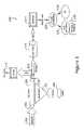
- FIG. 1is a schematic system block diagram of the portable biosensor system of the present invention
- FIG. 2is side, elevational, schematic view of the capillary tube, optical arrangement, and photosensor of the biosensor system of FIG. 1 ;
- FIG. 3is a end, cross-sectional view of the capillary tube of the biosensor system of FIG. 1 ;
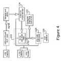
- FIG. 4is a high level, electrical block diagram of the biosensor system of FIG. 1 ;
- FIG. 5is an electrical schematic diagram of a preferred embodiment of the biosensor system of FIG. 1 .
- the threat of bioterrorismhas spawned a flurry of research focused on developing portable biosensor systems capable of rapidly and sensitively detecting proteins, cells, and other biomarkers.
- the present inventionfeatures a portable biosensor-based detection apparatus using a capillary tube, laser, photodetector and associated electronics to quickly and accurately detect the presence of a specific antigen or other analyte in a sample.
- the biosensor system of the present inventionis a portable capillary biosensor that utilizes fluorescent immunoassays inside a capillary tube (i.e., a capillary) to detect and quantify analytes.
- the capillaryforms a waveguide wherein the sample-containing capillary is illuminated along substantially its entire length.
- the resulting fluorescent emissionis then received (i.e., collected) at the end of the capillary using a photo-detector.
- FIG. 1there is shown a schematic, functional block diagram 100 of the portable biosensor apparatus of the invention.
- a capillary tube 102has a proximal end 104 where a sample 106 to be analyzed may be introduced.
- Capillary tube 102has an inner surface selectively coated with a suitable immobilized antibody or other suitable capture substance Such as RNA, DNA, spores, bacteria, whole cells, aptamers and other ligands. As discussed hereinbelow, the choice of capture antibody is dependent upon the target substance to be detected.
- waveguidesin a variety of formats including glass slides (planar waveguides), microarrays, fiber optics, and capillaries have been used as transduction methods for fluorescent immunoassay.
- Capillariesoffer several unique advantages over other waveguide forms or formats. First, it has been shown that the fluorescence signal accumulates along the length of the capillary 102 while the background noise remains substantially constant. This fact provides lower detection limits (i.e., higher sensitivity) compared to other waveguide forms. Second, the capillary 102 is multifunctional. Once the tube is placed in an instrument 100 , the sensing surface does not come into contact with the outside environment and the capillary becomes an integral part of the flow system.
- Rinsing and incubation stepsmay be accomplished by simply pumping the required solution into the instrument.
- the capillaryalso becomes the reaction vessel and the product formation therein can be monitored in real time.
- Capillary sensorscan also be coupled with electrophoresis or patterned for multi-analyte detection.
- a 635 nM wavelength VLM diode laser module having a power output of approximately 15 mW, manufactured by Coherent and supplied as Catalogue No. 0222-021-01has been found suitable for the application.
- Laser 108projects a substantially circular, 1 mm diameter beam.
- Laser 108is mounted in a pivot mount, not shown, that also acts as a heat sink. The pivot mount allows the excitation energy 110 to be tightly focused onto the capillary 102 without the need for any intervening, adjustable optical stages.
- a line-generating lens or gratingis placed in front of laser 108 to spread the circular output beam into a line of illumination along capillary tube 102 .
- Such an optical componentis well known to those of skill in the optical field and is not further described herein. It will be recognized that a number of suitable optical components exist for performing the beam spreading (e.g., line generating) function; the invention is not limited to a line-generating lens or grating. Rather, any optical component suitable for forming a line or field of radiant energy 110 along capillary tube 102 may be used.
- a pump 112is provided to both introduce and evacuate the sample to and from capillary tube 102 and, optionally, in cooperation with other apparatus components, not shown, to circulate the sample within capillary tube 102 .
- a miniature, variable-speed peristaltic pump 112such as Model No. SP100V0, pump manufactured by APT, Litchfield, Ill.
- the pump 112is connected to a 3-way switch, not shown, or other suitable control that permits selective operation of pump 112 at flow rates of approximately 0.18 ml/min (high speed) and 0.4 ml/min (low speed). The faster flow rate has been found useful for performing rinsing steps as described hereinbelow.
- a photosensor 114is disposed proximate a distal end 116 of capillary tube 102 via optical arrangement 118 .
- Photosensor 114monitors the fluorescence of the excited sample 106 within capillary tube 102 , shown schematically as emission 120 , and generates an electrical signal representative thereof.
- a photomultiplier tube or other sensitive photosensormay be used. Examples of other photosensors include photodiodes include photodiodes and infrared detectors, for example, Michelson Interferometers.
- optical arrangement 118 and detector (i.e., photosensor) 114are axially aligned with the central, longitudinal axis of capillary tube 102 .
- a conventional lens tube 150FIG. 2
- plano-convex lenses 152 , 154FIG. 2
- a fiber optical couplingcould be inserted between distal end 116 of capillary tube 102 and other optical arrangement 118 or photosensor 114 .
- the inventionis not limited to the particular photosensor 114 , optical arrangement 118 , or placement of the photosensor relative to capillary tube 102 chosen for purposes of disclosure. Rather, the invention covers any and all suitable photosensors 114 , optical arrangements 118 , and relative positions of photosensors 114 to capillary tube 102 .
- Signal processing electronics 122is operatively connected to photosensor 114 and receives an electrical signal therefrom.
- An analog-to-digital (A/D) converter and associated circuitry 124is used to drive an on-board display or readout 126 where quantitative/qualitative information regarding a sample being tested is displayed.
- an optional interface 128may be provided to allow attachment of a computer (e.g., a notebook computer, PDA, etc.) or other external device useful for processing, correlating, post analyzing, or otherwise processing and/or storing result data.
- Such interfacingmay be accomplished in a wide variety of ways including, but not limited to, serial and parallel direct connections, infrared communications ports, network (including wireless) connections, proprietary interfaces, and the like. As these interfacing techniques are considered well known to those of skill in the computer arts, they are not further described herein. The invention is seen to encompass any viable communication strategy.
- reagentsare introduced into capillary tube 102 adjacent proximal end 104 where they interact with the immobilized antibody 162 ( FIG. 3 ) or other suitable capture substance coated upon the inner surface 160 thereof.
- a fluorescent labeled antibody, a fluorescent labeled avidin, or a fluorescent ELISA using an avidin/alkaline phosphatase complexis introduced into capillary tube 102 .
- Alexa-Fluor 647is preferred due to its improved performance over Cy-5 when used to label tracer antibodies for sandwich immunoassays.
- other materialsmay be substituted for Alexa-Fluor 647.
- any other similar, suitable substances known to those of skill in the artmay be substituted therefor.
- capillary tube 102is a fused silica capillary approximately 38 mm long having an inside diameter of approximately 0.7 mm and an outside diameter of approximately 0.85 mm.
- the capillary tube 102is available from Polymicro Technologies, Phoenix, Ariz.
- Capillary tube 102is mounted in a custom scaffold 142 that contains a longitudinal window that allows the line laser beam 110 ( FIG. 1 ) to illuminate capillary 102 along substantially the entire length thereof. Emission (e.g., radiation) is collected through a transparent window 146 disposed at a distal end 148 of scaffold 142 .
- scaffold 142is formed from polystyrene. Polystyrene was chosen for its weight, rigidity, and ease of machining in constructing prototypes. However, it will be recognized that other lightweight but rigid material such as computer-milled aluminum and Teflon with 70% glass may also be easily substituted for polystyrene.
- a stackable lens tube 150obtained from Thorlabs, Newton, N.J., is abutted to and axially aligned with the transparent window 146 .
- lens tube 150is approximately 3 inches long and has a diameter of approximately 1 inch.
- Lens tube 150supports optical components, for example a pair of plano-convex lenses 152 , 154 and a long-pass interference filter (e.g., a 650 nm low-pass filter 156 obtained from Omega Optical, Brattleboro, Vt.).
- Lenses 152 , 154 and filter 156form optical arrangement 118 as shown in FIG. 1 .
- the lens tube 150is threaded on the inside.
- Retaining ringsare used to hold the optics 152 , 154 , 156 in place therein. This arrangement allows the optical components 152 , 154 , 156 to be optimally distance-adjusted with respect to one another, to the end of capillary tube 102 , and to photosensor 114 , respectively, and then secured in place within lens tube 150 .
- Photosensor module (i.e., photodetector) 114is attached to distal end 158 of lens tube 150 via a custom made Nylon fitting 160 .
- a Catalog No. HC-5784-20 photosensor manufactured by Hamamatsu (Japan)has been found suitable for the application.
- Nylon fitting 160has a diameter of approximately 1-inch and a thickness of approximately 0.5 inches.
- Nylon fitting 160is secured into lens tube 150 with retaining rings, not shown, and is equipped with mounting screws compatible with photosensor 114 . This allows lens tube 150 to be attached to the photosensor module 114 via mating, pre-drilled holes on the front, light-receiving surface thereof.
- the photosensor module 114contains a photomultiplier tube, not shown, a built-in high voltage power supply, and a low noise amplifier that converts the output current from the photomultiplier tube to voltage representative thereof.
- a well-known Hamamatsu HC 120 bench top analyzerit was found that the 5784 photosensor 114 exhibited lower noise than did the HC 120 instrument. However, 5784 photosensor 114 had lower gain resulting in decreased detector sensitivity. The lower sensitivity was overcome somewhat by using a higher power (e.g., 15 mW vs. 12 mW) laser 108 in the portable instrument.
- the rigid alignment provided by the sensor platform (i.e., capillary tube 102 /scaffold 142 ) optical arrangement 118 , and photodetector 114typically were found to require no further alignment adjustment after assembly. The arrangement has been found adequate for field use where the system may be exposed to some shock during transportation and use.
- capillary tube 102there is shown an end, sectional, schematic view of capillary tube 102 .
- capture materiale.g., an immobilized antibody, etc.
- Many different materialsmay be immobilized on interior surface 160 of capillary tube 102 .
- the selection of capture material 162depends, of course, upon the analyte to be detected and/or quantified.
- goat anti-mouse IgG, mouse IgG whole molecule, biotinylated goat anti-mouse and the phosphatase substrate para-nitrophenyl phosphate (PNPP)may be utilized as required.
- the aforementioned materialsare available from Pierce Biotech, Rockland, Ill.
- the target analyteis captured by immobilized antibody 162 on the inner surface 160 of capillary tube 102 and then detected using a fluorescent labeled antibody, a fluorescent labeled avidin, or a fluorescent ELISA in conjunction with an avidin/alkaline phosphatase complex.
- a fluorescent labeled antibodyfor fluorescence detection, Alexa-Fluor 647 was selected due to its reported improved performance over Cy-5 when used to label tracer antibodies for sandwich immunoassays. It will be recognized, however, that a single capture antibody 162 may be used.
- the systemcan also be adapted for multi-analyte detection by the use of a patterned capillary tube 102 wherein more than one capture antibody 162 may be applied to surface 160 .
- multiple capillary tubes 102each coated with a different capture antibody 162 and disposed in a parallel arrangement, may be used to detect multiple analytes in a sample.
- Capillary tubes 102were first prepared assuming the desired analyte to be goat anti-mouse IgG by serially interconnecting multiple capillary tubes 102 using TygonTM tubing. Solutions were drawn into the string of capillary tubes 102 using a plastic syringe, not shown. A syringe having a toluene-resistant plastic plunger and a lure-lock tip were found suitable.
- Immobilization of the goat anti-mouse capture antibodywas achieved using covalent chemistry well known to those of skill in the art.
- the capillary tubes 102were incubated under nitrogen with a 2% solution of 3-mercaptopropyl trimethoxy silane in anhydrous toluene.
- the capillary tubes 102were then treated with the hetero-bi-functional cross linker (N-[ ⁇ -maleimidobutyryloxy]succinimide ester)(GMBS).
- Goat anti-mouse capture antibodies at a concentration of 10 ⁇ g/ml in phosphate buffered saline (PBS)were then attached to the capillary tube 102 via the crosslinker by an overnight, refrigerated incubation.
- PBSphosphate buffered saline
- a 10 ⁇ g/ml solution of goat IgG whole moleculewas immobilized in place of the anti-goat capture antibody.
- the capillary tubes 102were blocked with a 1 mg/ml solution of BSA.
- conventional colorimetric sandwich ELISA assayswere performed using the same antibody-antigen combination as used in the capillary tubes 102 .
- a 96-well micro-titer mouse in pH 9.6 carbonate buffer treated for 2 hours at room temperaturewas performed.
- the micro-titer plateswere rinsed thrice and blocked with a 10 mg/ml BSA solution in PBS with another 2-hour incubation at room temperature.
- the ELISA plateswere exposed to the antigen (mouse IgG) standards for 1 hour followed by a rinse step and an hour exposure to 10 ⁇ g/ml solution of biotinylated goat anti-mouse.
- the wellswere exposed to the avidin/alkaline phosphatase substrate in pH 8.0 Tris buffered saline with 5 mg/ml BSA for 1 hour.
- the enzyme complexwas tittered at ratios of 1:5000, 1:10,000, 1:20,000 and 1:40,000.
- the PNPP substrate in DEA buffer, pH 9.6,was added to each well and incubated for 20 minutes. Plates were then read at 405 nm on a Biotek Elx800 microplate reader.
- Direct binding assayswere initially performed using the portable instrument of the present invention to compare the signal generated by an avidin-Alexa Fluor 647 conjugate and an avidin-alkaline phosphatase complex coupled with DDAO-phosphate as a substrate.
- the mouse IgGwas immobilized at a constant concentration in the capillary tube 102 and the goat anti-mouse/biotin (GAMB) was diluted and used as the standard to be detected.
- the GAMB standardsprepared in phosphate buffered saline with 1 mg/ml BSA and Tween 20 (PBSTB) was drawn into the capillary 102 using a plastic syringe and then incubated for approximately 15 minutes.
- the capillary 102was then rinsed with PBSTB and a 1:20,000 solution of the avidin/AP complex in pH 8.0 tris buffered saline with 5.0 mg/ml BSA was added and incubated for approximately 5 minutes.
- the capillary 102was then inserted into the instrument and a buffer was flowed therethrough through at a flow rate of approximately 0.19 ml/min. After a few seconds, the inlet was switched over to the substrate (20 ⁇ M DDAO in pH 9.8 Tris buffer with 100 mg/L MgCl 2 ).
- the term substraterefers to the molecules used for amplification of immunological reactions commonly used in Enzyme linked Immunosorbent Assay (ELISA).
- ELISAis considered the “gold standard” for immunological analytical techniques.
- an antibodyprimary
- an antigenor target species
- the antigen, (or target species)specifically binds to the capture antibody.
- a labeled second antibodyspecifically recognizes another epitope on the antigen (or a site on the target).
- the secondary antibodyis conjugated to an enzyme and doubles up as the detection antibody.
- the final step of the assayis amplification, which is made possible by the addition of a substrate upon which the enzyme acts with a very high turnover rate giving a detectable product.
- the endpoint of the enzymatic reactiontypically leads to a colored product that is detected spectrophotometrically.
- the absorbanceis used to quantify the amount of antigen or target species present in the sample.
- the pump 112When the substrate passed into the capillary, the pump 112 was shut off and the enzymatic cleavage of DDAO was allowed to proceed.
- the GAMB standardswere incubated in the same manner as described hereinabove. However, after the incubation step, the capillary 102 was placed in the potable instrument. Buffer was flowed through the capillary 102 and a baseline voltage was recorded for approximately 20 seconds. A solution of avidin-AF647 (10 ⁇ g/ml in PBSTB) was then introduced into capillary tube 102 . After the avidin-AF647 solution had entered the capillary tube 102 , the pump 112 was switched off and incubation of approximately 5 minutes was allowed. After the incubation period, buffer was reintroduced into capillary tube 102 and the pump 112 was operated at high speed for approximately 30 seconds. Following the buffer rinse, the electrical output signal was recorded with an increase in voltage being indicative of surface bound AF647.
- Capillary sandwich fluorescent ELISA assayswere performed using the capillaries 102 with immobilized goat anti-mouse IgG. Capillaries 102 were strung onto syringes using Tygon tubing. An incubation sequence having the indicated steps was then performed:
- Controls usedwere identical to those described for the fluorescent ELISA hereinabove.
- Sandwich assays using the AF-647 labeled goat anti-mouse tracer antibodywere performed in a similar fashion. After incubation with the antigen standards for 10 minutes, the capillary 102 was inserted into the instrument. A solution of 10 ⁇ g/ml AF-647 labeled goat anti-mouse in PBSTB was introduced into capillary tube 102 . The pump 112 was shut off and the antibody was allowed to incubate for various times in the range of between approximately 4 and 15 minutes to optimize the signal to noise ratio. Controls consisted of capillary tubes 102 prepared with no capture antibody as well as blank capillary tubes 102 with no antigen present.
- Alexa-Fluor 647 NHS-ester, Alexa Fluor 647-labeled streptavidin and the phosphatase substrate 9H-(1,3-dichloro-9,9-dimethylacridin-2-one-7-yl) phosphate, diammonium salt DDAO-phosphate)were purchased from Molecular Probes, Eugene, Oreg. Goat anti-mouse antibodies to be used as tracers were labeled with a 15-fold molar excess of Alexa-Fluor 647 NHS-ester at pH 8.0 and incubated overnight in the refrigerator.
- Unbound AF 647was removed with protein desalting spin columns (Pierce Biotech, Rockland, Ill.) according to the manufacturer's instructions.
- the dye:protein ratiowas determined to be 4.2:1 by measuring the absorbance at 280 and 650 nm on a Hewlett-Packard diode array spectrophotometer and making the calculations according to the manufacturer's instructions.
- Bovine Serum Albumin (BSA) and alkaline phosphatase labeled avidinwere purchased from Sigma, ST. Louis, Mo.
- the system of FIG. 1may be miniaturized for portable applications. It is desirable that such a portable instrument exhibit four important characteristics. First, size and weight should be minimized to create in instrument readily usable in the field. Ideally, all power for the instrument should be supplied by internal batteries, preferably rechargeable batteries. Second, the instrument must be rugged to withstand rough handling to which such an instrument is typically subjected. As the instrument may contain a fragile capillary tube and optical components requiring relatively precise alignment, proper shock mounting of components is required. Third, the instrument should be sensitive to allow precise quantitative/qualitative measurements to be performed in as short an amount of time as possible. Finally, the instrument should be relatively inexpensive.
- the prototype used for purposes of disclosurefulfills these four requirements.
- the prototypeexhibits a weight of approximately 33.5 pounds, or 15.4 kg, and is packaged in approximately a 12 ⁇ 4 ⁇ 5 inch volume. It is believed that the size of the instrument may be further reduced, ultimately to the size of a typical PDA or similar hand-held instrument.
- the electronic signal processing portion 122consists an low-pass filter 170 , an integrating voltmeter 124 , a self-contained digital readout 126 , and an optional computer interface 122 .
- low-pass filter 170An electrical signal output of photosensor 114 is connected to the input of low-pass filter 170 .
- low-pass filter 170is implemented as a Butterworth filter consisting of an operational amplifier (op-amp) having an appropriate feedback network to form the desired cut-off frequency and slope. Butterworth filters are well known to those of skill in the electronic design arts and are not further described herein.
- FIG. 5there is shown an exemplary circuit diagram of an embodiment of the inventive, portable biosensor system.
- an LM-741 op-ampis used.
- a filter circuit having an approximately 30 Hz cut-off frequencyhas been chosen. It will be recognized that other suitable low-pass filter topologies and or implementations may be substituted for the Butterworth filter chosen for purposes of disclosure. Consequently, the invention is not considered limited to any particular filter design. It will be further recognized that circuit designs may be provided without any low-pass filter. The present invention is intended to include such designs as well.
- the output of low-pass filter 170is connected to the input of an A/D converter 124 forming an integrating voltmeter.
- the output of integrating voltmeter 124is connected to the input of a digital display device 126 (i.e., a digital readout).
- Integrating voltmeter 124may be implemented using an IC7106 analog-to-digital (A/D) converter adapted to directly drive an LCD display device 126 .
- the IC7106 chipaccepts an absolute voltage reference (available from the power supply of the portable instrument) using a calibration potentiometer 174 or other suitable arrangement. This allows accurate, absolute voltage measurements to be performed, typically at a rate of approximately 3 readings per second.
- Reading capability in the range of 0-5 voltshas been found satisfactory, even when high concentrations of fluorescent dyes are utilized for an assay.
- the digital readout 126 of the apparatushas been found to be suitably stable to allow manual recording of readings by an operator of the instrument.
- a 3.5-digit digital displayhas been found to be adequate.
- the prototypecan be operated with a power supply of both plus and minus voltages in the range of approximately 12-15V 176 , 178 , respectively.
- Voltage regulators 182 , 184maintain a constant voltage to the circuitry as output voltage from batteries 176 , 178 decreases.
- Series-connected 9-volt batterieshave been found suitable to provide voltages 176 , 178 .
- a separate 5-volt power supplyconsisting of a battery 186 and voltage regulator 188 is used to power laser 108 .
- Battery lifetimeis typically not a major concern as both pump 112 and laser 108 are intermittently operated.
- it is possible to power the laser from power supply 176it is desirable to use a separate power supply 186 or 188 to avoid any electrical transients that might potentially damage laser 108 .
- batteries of positive power supply 176would most likely be discharged more rapidly would than the batteries of negative power supply 178 .
- the output signal from the low-pass filter 170is fairly clean and typically does not require complex lock-in amplification or other specialized signal processing.
- the photosensor module 114 , CMOS A/D converter (i.e., integrating voltmeter) 124 , filter circuit 180 and LCD display 126are all driven by the same power supply, typically consisting of four 9-volt batteries. In theory, the power supply can last for a maximum of 70 hours while powering all of the above components. However, if pump 112 and laser 108 ( FIG. 1 ) are run from the same power supply 176 , typical battery lifetimes are reduced to approximately 10 hours. As previously stated, either non-rechargeable or rechargeable batteries may be used.
- Rechargeable batteriesare preferable and built-in recharging capability, not shown, may be provided if desired.
- the low power consuming photosensor module 114makes possible a biosensor containing two or more of these photosensor modules 114 configured for multi-analyte or multiple sample analysis feasible.
Landscapes
- Health & Medical Sciences (AREA)
- Immunology (AREA)
- Life Sciences & Earth Sciences (AREA)
- Chemical & Material Sciences (AREA)
- Engineering & Computer Science (AREA)
- Pathology (AREA)
- Biochemistry (AREA)
- General Health & Medical Sciences (AREA)
- General Physics & Mathematics (AREA)
- Analytical Chemistry (AREA)
- Physics & Mathematics (AREA)
- Urology & Nephrology (AREA)
- Biomedical Technology (AREA)
- Hematology (AREA)
- Molecular Biology (AREA)
- Nuclear Medicine, Radiotherapy & Molecular Imaging (AREA)
- Biotechnology (AREA)
- Cell Biology (AREA)
- Microbiology (AREA)
- Food Science & Technology (AREA)
- Medicinal Chemistry (AREA)
- Investigating, Analyzing Materials By Fluorescence Or Luminescence (AREA)
- Investigating Or Analysing Materials By The Use Of Chemical Reactions (AREA)
Abstract
Description
Claims (21)
Priority Applications (3)
| Application Number | Priority Date | Filing Date | Title |
|---|---|---|---|
| US11/451,842US7708944B1 (en) | 2006-06-13 | 2006-06-13 | Ultra-sensitive, portable capillary sensor |
| US12/755,578US8414844B2 (en) | 2006-06-13 | 2010-04-07 | Ultra-sensitive, portable capillary sensor |
| US13/786,931US20130183750A1 (en) | 2006-06-13 | 2013-03-06 | Ultra-sensitive portable capillary sensor |
Applications Claiming Priority (1)
| Application Number | Priority Date | Filing Date | Title |
|---|---|---|---|
| US11/451,842US7708944B1 (en) | 2006-06-13 | 2006-06-13 | Ultra-sensitive, portable capillary sensor |
Related Child Applications (1)
| Application Number | Title | Priority Date | Filing Date |
|---|---|---|---|
| US12/755,578ContinuationUS8414844B2 (en) | 2006-06-13 | 2010-04-07 | Ultra-sensitive, portable capillary sensor |
Publications (1)
| Publication Number | Publication Date |
|---|---|
| US7708944B1true US7708944B1 (en) | 2010-05-04 |
Family
ID=42124812
Family Applications (3)
| Application Number | Title | Priority Date | Filing Date |
|---|---|---|---|
| US11/451,842Expired - Fee RelatedUS7708944B1 (en) | 2006-06-13 | 2006-06-13 | Ultra-sensitive, portable capillary sensor |
| US12/755,578Expired - Fee RelatedUS8414844B2 (en) | 2006-06-13 | 2010-04-07 | Ultra-sensitive, portable capillary sensor |
| US13/786,931AbandonedUS20130183750A1 (en) | 2006-06-13 | 2013-03-06 | Ultra-sensitive portable capillary sensor |
Family Applications After (2)
| Application Number | Title | Priority Date | Filing Date |
|---|---|---|---|
| US12/755,578Expired - Fee RelatedUS8414844B2 (en) | 2006-06-13 | 2010-04-07 | Ultra-sensitive, portable capillary sensor |
| US13/786,931AbandonedUS20130183750A1 (en) | 2006-06-13 | 2013-03-06 | Ultra-sensitive portable capillary sensor |
Country Status (1)
| Country | Link |
|---|---|
| US (3) | US7708944B1 (en) |
Cited By (31)
| Publication number | Priority date | Publication date | Assignee | Title |
|---|---|---|---|---|
| US20100110431A1 (en)* | 2008-11-05 | 2010-05-06 | Goodrich Corporation | Apparatus and method for in-flight detection of airborne water droplets and ice crystals |
| US20110053290A1 (en)* | 2009-08-28 | 2011-03-03 | Electronics And Telecommunications Research Institute | Light addressing biosensor chip and method of driving the same |
| US20110273869A1 (en)* | 2010-05-10 | 2011-11-10 | Richard Redpath | Cost Effective Apparatus for a Heterogeneous Battery Operated Laser Illumination System |
| US20120142017A1 (en)* | 2010-12-06 | 2012-06-07 | Electronics And Telecommunications Research Institute | Biosensor device and manufacturing method thereof |
| US20130197334A1 (en)* | 2010-03-16 | 2013-08-01 | Gilupi Gmbh | Biodetector |
| CN103983769A (en)* | 2014-03-25 | 2014-08-13 | 中国海洋大学 | Preparation method for nano-gold immunity chromatography capillary |
| WO2015005872A1 (en)* | 2013-07-10 | 2015-01-15 | Agency For Science, Technology And Research | Analyte detection device |
| US9296820B2 (en) | 2003-11-05 | 2016-03-29 | Roche Glycart Ag | Polynucleotides encoding anti-CD20 antigen binding molecules with increased Fc receptor binding affinity and effector function |
| CN105738338A (en)* | 2016-03-04 | 2016-07-06 | 曲阜师范大学 | Water-sensitive fluorescent capillary tube based on amino silanization zinc oxide as well as preparation method and application of water-sensitive fluorescent capillary tube |
| US9506908B2 (en) | 2014-10-06 | 2016-11-29 | Alveo Technologies, Inc. | System for detection of analytes |
| US9766221B2 (en) | 2015-01-30 | 2017-09-19 | Quipip, Llc | Systems, apparatus and methods for testing and predicting the performance of concrete mixtures |
| US9776455B2 (en) | 2014-02-28 | 2017-10-03 | Quipip, Llc | Systems, methods and apparatus for providing to a driver of a vehicle carrying a mixture real-time information relating to a characteristic of the mixture |
| WO2017188463A1 (en)* | 2016-04-25 | 2017-11-02 | 주식회사 디엠엑스 | Body fluid analysis device, biosensor, and method for producing biosensor |
| US9829491B2 (en) | 2009-10-09 | 2017-11-28 | The Research Foundation For The State University Of New York | pH-insensitive glucose indicator protein |
| US9836801B2 (en) | 2012-01-23 | 2017-12-05 | Quipip, Llc | Systems, methods and apparatus for providing comparative statistical information in a graphical format for a plurality of markets using a closed-loop production management system |
| US9840026B2 (en) | 2012-01-23 | 2017-12-12 | Quipip, Llc | Systems, methods and apparatus for providing comparative statistical information for a plurality of production facilities in a closed-loop production management system |
| US9921182B2 (en) | 2014-10-06 | 2018-03-20 | ALVEO Technologies Inc. | System and method for detection of mercury |
| US10065403B2 (en) | 2009-11-23 | 2018-09-04 | Cyvek, Inc. | Microfluidic assay assemblies and methods of manufacture |
| US10076752B2 (en) | 2009-11-23 | 2018-09-18 | Cyvek, Inc. | Methods and systems for manufacture of microarray assay systems, conducting microfluidic assays, and monitoring and scanning to obtain microfluidic assay results |
| US10184928B2 (en) | 2014-01-29 | 2019-01-22 | Quipip, Llc | Measuring device, systems, and methods for obtaining data relating to condition and performance of concrete mixtures |
| US10196678B2 (en) | 2014-10-06 | 2019-02-05 | ALVEO Technologies Inc. | System and method for detection of nucleic acids |
| US10220385B2 (en)* | 2009-11-23 | 2019-03-05 | Cyvek, Inc. | Micro-tube particles for microfluidic assays and methods of manufacture |
| US10228367B2 (en) | 2015-12-01 | 2019-03-12 | ProteinSimple | Segmented multi-use automated assay cartridge |
| US10252263B2 (en) | 2009-11-23 | 2019-04-09 | Cyvek, Inc. | Microfluidic devices and methods of manufacture and use |
| US10352899B2 (en) | 2014-10-06 | 2019-07-16 | ALVEO Technologies Inc. | System and method for detection of silver |
| US10408825B2 (en)* | 2015-05-19 | 2019-09-10 | Electronics And Telecommunications Research Institute | Biosensor |
| US10627358B2 (en) | 2014-10-06 | 2020-04-21 | Alveo Technologies, Inc. | Method for detection of analytes |
| US10786800B2 (en) | 2009-11-23 | 2020-09-29 | Cyvek, Inc. | Methods and systems for epi-fluorescent monitoring and scanning for microfluidic assays |
| US11465141B2 (en) | 2016-09-23 | 2022-10-11 | Alveo Technologies, Inc. | Methods and compositions for detecting analytes |
| US12109019B2 (en) | 2022-12-15 | 2024-10-08 | Adaptyx Biosciences, Inc. | Systems and methods for analyte detection |
| US12275007B2 (en) | 2018-12-20 | 2025-04-15 | Alveo Technologies, Inc. | Handheld impedance-based diagnostic test system for detecting analytes |
Families Citing this family (5)
| Publication number | Priority date | Publication date | Assignee | Title |
|---|---|---|---|---|
| US7708944B1 (en) | 2006-06-13 | 2010-05-04 | Research Foundation Of State University Of New York | Ultra-sensitive, portable capillary sensor |
| US20130089876A1 (en)* | 2010-04-19 | 2013-04-11 | Research Foundation Of State University Of New York | Capillary biosensor system and its method of use |
| AU2015323511B2 (en)* | 2014-09-26 | 2019-10-03 | Sofradim Production | System and method for early detection of post-surgery infection |
| US20160349338A1 (en)* | 2015-05-25 | 2016-12-01 | James Bradley | Quantitation of atoms by means of non-particulate radiation |
| CN110770552B (en)* | 2017-06-14 | 2023-09-12 | 陈敬红 | High-sensitivity optical detection system |
Citations (15)
| Publication number | Priority date | Publication date | Assignee | Title |
|---|---|---|---|---|
| US5011608A (en)* | 1988-11-18 | 1991-04-30 | Dragana Damjanovic | Biogenic amine assay using HPLC-ECD |
| US5205291A (en)* | 1988-11-08 | 1993-04-27 | Health Research, Inc. | In vivo fluorescence photometer |
| US5281825A (en)* | 1991-09-05 | 1994-01-25 | The University Of Maryland School Of Medicine | Phase fluorometry using a modulated electroluminescent lamp as a light source |
| US5293210A (en)* | 1992-04-24 | 1994-03-08 | Becton, Dickinson And Company | Detection of bacteria in blood culture bottles by time-resolved light scattering and absorption measurement |
| US5395502A (en)* | 1988-11-14 | 1995-03-07 | Anthony R. Torres | Apparatus for performing and universally detecting capillary isoelectric focusing without mobilization using concentration gradient imaging systems |
| US5503994A (en)* | 1993-10-08 | 1996-04-02 | The Board Of Trustees Of The Leland Stanford Junior University | System for sample detection with compensation for difference in sensitivity to detection of components moving at different velocities |
| US5610405A (en)* | 1993-03-24 | 1997-03-11 | Semiconductor Energy Laboratory, Co., Ltd. | Electronic device for measuring light properties |
| US6020207A (en)* | 1998-06-17 | 2000-02-01 | World Precision Instruments, Inc. | Optical analysis technique and sensors for use therein |
| US6020209A (en)* | 1997-04-28 | 2000-02-01 | The United States Of America As Represented By The Secretary Of The Navy | Microcapillary-based flow-through immunosensor and displacement immunoassay using the same |
| US6258606B1 (en) | 1996-07-09 | 2001-07-10 | Nanogen, Inc. | Multiplexed active biologic array |
| US6277627B1 (en) | 1997-12-31 | 2001-08-21 | Duke University | Biosensor |
| US6294392B1 (en) | 1999-07-21 | 2001-09-25 | The Regents Of The University Of California | Spatially-encoded analyte detection |
| US6767733B1 (en) | 2001-10-10 | 2004-07-27 | Pritest, Inc. | Portable biosensor apparatus with controlled flow |
| US6835946B2 (en)* | 2000-12-04 | 2004-12-28 | Fuji Photo Film Co., Ltd. | Image reading method and apparatus |
| US6929945B2 (en)* | 2002-12-09 | 2005-08-16 | Advanced Fluidix Laboratories Llc | Male fertility assay method and device |
Family Cites Families (7)
| Publication number | Priority date | Publication date | Assignee | Title |
|---|---|---|---|---|
| US5760406A (en)* | 1996-06-03 | 1998-06-02 | Powers; Linda | Method and apparatus for sensing the presence of microbes |
| EP1412724B1 (en) | 2001-07-25 | 2016-03-23 | Life Technologies Corporation | Time-delay integration in electrophoretic detection systems |
| DK1432786T3 (en) | 2001-09-06 | 2009-10-26 | Rapid Micro Biosystems Inc | Rapid detection of replicated cells |
| US7547904B2 (en) | 2005-12-22 | 2009-06-16 | Palo Alto Research Center Incorporated | Sensing photon energies emanating from channels or moving objects |
| US8137626B2 (en) | 2006-05-19 | 2012-03-20 | California Institute Of Technology | Fluorescence detector, filter device and related methods |
| US7708944B1 (en) | 2006-06-13 | 2010-05-04 | Research Foundation Of State University Of New York | Ultra-sensitive, portable capillary sensor |
| US20130089876A1 (en) | 2010-04-19 | 2013-04-11 | Research Foundation Of State University Of New York | Capillary biosensor system and its method of use |
- 2006
- 2006-06-13USUS11/451,842patent/US7708944B1/ennot_activeExpired - Fee Related
- 2010
- 2010-04-07USUS12/755,578patent/US8414844B2/ennot_activeExpired - Fee Related
- 2013
- 2013-03-06USUS13/786,931patent/US20130183750A1/ennot_activeAbandoned
Patent Citations (15)
| Publication number | Priority date | Publication date | Assignee | Title |
|---|---|---|---|---|
| US5205291A (en)* | 1988-11-08 | 1993-04-27 | Health Research, Inc. | In vivo fluorescence photometer |
| US5395502A (en)* | 1988-11-14 | 1995-03-07 | Anthony R. Torres | Apparatus for performing and universally detecting capillary isoelectric focusing without mobilization using concentration gradient imaging systems |
| US5011608A (en)* | 1988-11-18 | 1991-04-30 | Dragana Damjanovic | Biogenic amine assay using HPLC-ECD |
| US5281825A (en)* | 1991-09-05 | 1994-01-25 | The University Of Maryland School Of Medicine | Phase fluorometry using a modulated electroluminescent lamp as a light source |
| US5293210A (en)* | 1992-04-24 | 1994-03-08 | Becton, Dickinson And Company | Detection of bacteria in blood culture bottles by time-resolved light scattering and absorption measurement |
| US5610405A (en)* | 1993-03-24 | 1997-03-11 | Semiconductor Energy Laboratory, Co., Ltd. | Electronic device for measuring light properties |
| US5503994A (en)* | 1993-10-08 | 1996-04-02 | The Board Of Trustees Of The Leland Stanford Junior University | System for sample detection with compensation for difference in sensitivity to detection of components moving at different velocities |
| US6258606B1 (en) | 1996-07-09 | 2001-07-10 | Nanogen, Inc. | Multiplexed active biologic array |
| US6020209A (en)* | 1997-04-28 | 2000-02-01 | The United States Of America As Represented By The Secretary Of The Navy | Microcapillary-based flow-through immunosensor and displacement immunoassay using the same |
| US6277627B1 (en) | 1997-12-31 | 2001-08-21 | Duke University | Biosensor |
| US6020207A (en)* | 1998-06-17 | 2000-02-01 | World Precision Instruments, Inc. | Optical analysis technique and sensors for use therein |
| US6294392B1 (en) | 1999-07-21 | 2001-09-25 | The Regents Of The University Of California | Spatially-encoded analyte detection |
| US6835946B2 (en)* | 2000-12-04 | 2004-12-28 | Fuji Photo Film Co., Ltd. | Image reading method and apparatus |
| US6767733B1 (en) | 2001-10-10 | 2004-07-27 | Pritest, Inc. | Portable biosensor apparatus with controlled flow |
| US6929945B2 (en)* | 2002-12-09 | 2005-08-16 | Advanced Fluidix Laboratories Llc | Male fertility assay method and device |
Cited By (37)
| Publication number | Priority date | Publication date | Assignee | Title |
|---|---|---|---|---|
| US9296820B2 (en) | 2003-11-05 | 2016-03-29 | Roche Glycart Ag | Polynucleotides encoding anti-CD20 antigen binding molecules with increased Fc receptor binding affinity and effector function |
| US7986408B2 (en)* | 2008-11-05 | 2011-07-26 | Rosemount Aerospace Inc. | Apparatus and method for in-flight detection of airborne water droplets and ice crystals |
| US20100110431A1 (en)* | 2008-11-05 | 2010-05-06 | Goodrich Corporation | Apparatus and method for in-flight detection of airborne water droplets and ice crystals |
| US20110053290A1 (en)* | 2009-08-28 | 2011-03-03 | Electronics And Telecommunications Research Institute | Light addressing biosensor chip and method of driving the same |
| US9829491B2 (en) | 2009-10-09 | 2017-11-28 | The Research Foundation For The State University Of New York | pH-insensitive glucose indicator protein |
| US10786800B2 (en) | 2009-11-23 | 2020-09-29 | Cyvek, Inc. | Methods and systems for epi-fluorescent monitoring and scanning for microfluidic assays |
| US10076752B2 (en) | 2009-11-23 | 2018-09-18 | Cyvek, Inc. | Methods and systems for manufacture of microarray assay systems, conducting microfluidic assays, and monitoring and scanning to obtain microfluidic assay results |
| US10065403B2 (en) | 2009-11-23 | 2018-09-04 | Cyvek, Inc. | Microfluidic assay assemblies and methods of manufacture |
| US10220385B2 (en)* | 2009-11-23 | 2019-03-05 | Cyvek, Inc. | Micro-tube particles for microfluidic assays and methods of manufacture |
| US10252263B2 (en) | 2009-11-23 | 2019-04-09 | Cyvek, Inc. | Microfluidic devices and methods of manufacture and use |
| US20130197334A1 (en)* | 2010-03-16 | 2013-08-01 | Gilupi Gmbh | Biodetector |
| US20110273869A1 (en)* | 2010-05-10 | 2011-11-10 | Richard Redpath | Cost Effective Apparatus for a Heterogeneous Battery Operated Laser Illumination System |
| US20120142017A1 (en)* | 2010-12-06 | 2012-06-07 | Electronics And Telecommunications Research Institute | Biosensor device and manufacturing method thereof |
| US9836801B2 (en) | 2012-01-23 | 2017-12-05 | Quipip, Llc | Systems, methods and apparatus for providing comparative statistical information in a graphical format for a plurality of markets using a closed-loop production management system |
| US9840026B2 (en) | 2012-01-23 | 2017-12-12 | Quipip, Llc | Systems, methods and apparatus for providing comparative statistical information for a plurality of production facilities in a closed-loop production management system |
| WO2015005872A1 (en)* | 2013-07-10 | 2015-01-15 | Agency For Science, Technology And Research | Analyte detection device |
| US10184928B2 (en) | 2014-01-29 | 2019-01-22 | Quipip, Llc | Measuring device, systems, and methods for obtaining data relating to condition and performance of concrete mixtures |
| US9776455B2 (en) | 2014-02-28 | 2017-10-03 | Quipip, Llc | Systems, methods and apparatus for providing to a driver of a vehicle carrying a mixture real-time information relating to a characteristic of the mixture |
| CN103983769A (en)* | 2014-03-25 | 2014-08-13 | 中国海洋大学 | Preparation method for nano-gold immunity chromatography capillary |
| CN103983769B (en)* | 2014-03-25 | 2015-11-18 | 中国海洋大学 | A kind of preparation method of nm of gold immunochromatography kapillary |
| US9921182B2 (en) | 2014-10-06 | 2018-03-20 | ALVEO Technologies Inc. | System and method for detection of mercury |
| US10627358B2 (en) | 2014-10-06 | 2020-04-21 | Alveo Technologies, Inc. | Method for detection of analytes |
| US10196678B2 (en) | 2014-10-06 | 2019-02-05 | ALVEO Technologies Inc. | System and method for detection of nucleic acids |
| US11473128B2 (en) | 2014-10-06 | 2022-10-18 | Alveo Technologies, Inc. | System and method for detection of nucleic acids |
| US10626448B2 (en) | 2014-10-06 | 2020-04-21 | Alveo Technologies, Inc. | System and method for detection of nucleic acids |
| US9506908B2 (en) | 2014-10-06 | 2016-11-29 | Alveo Technologies, Inc. | System for detection of analytes |
| US10352899B2 (en) | 2014-10-06 | 2019-07-16 | ALVEO Technologies Inc. | System and method for detection of silver |
| US10458971B2 (en) | 2015-01-30 | 2019-10-29 | Quipip, Llc | Systems, apparatus and methods for testing and predicting the performance of concrete mixtures |
| US10983106B2 (en) | 2015-01-30 | 2021-04-20 | Quipip, Llc | Systems, apparatus and methods for testing and predicting the performance of concrete mixtures |
| US9766221B2 (en) | 2015-01-30 | 2017-09-19 | Quipip, Llc | Systems, apparatus and methods for testing and predicting the performance of concrete mixtures |
| US10408825B2 (en)* | 2015-05-19 | 2019-09-10 | Electronics And Telecommunications Research Institute | Biosensor |
| US10228367B2 (en) | 2015-12-01 | 2019-03-12 | ProteinSimple | Segmented multi-use automated assay cartridge |
| CN105738338A (en)* | 2016-03-04 | 2016-07-06 | 曲阜师范大学 | Water-sensitive fluorescent capillary tube based on amino silanization zinc oxide as well as preparation method and application of water-sensitive fluorescent capillary tube |
| WO2017188463A1 (en)* | 2016-04-25 | 2017-11-02 | 주식회사 디엠엑스 | Body fluid analysis device, biosensor, and method for producing biosensor |
| US11465141B2 (en) | 2016-09-23 | 2022-10-11 | Alveo Technologies, Inc. | Methods and compositions for detecting analytes |
| US12275007B2 (en) | 2018-12-20 | 2025-04-15 | Alveo Technologies, Inc. | Handheld impedance-based diagnostic test system for detecting analytes |
| US12109019B2 (en) | 2022-12-15 | 2024-10-08 | Adaptyx Biosciences, Inc. | Systems and methods for analyte detection |
Also Published As
| Publication number | Publication date |
|---|---|
| US20100187106A1 (en) | 2010-07-29 |
| US8414844B2 (en) | 2013-04-09 |
| US20130183750A1 (en) | 2013-07-18 |
Similar Documents
| Publication | Publication Date | Title |
|---|---|---|
| US7708944B1 (en) | Ultra-sensitive, portable capillary sensor | |
| US20210172942A1 (en) | Hollow polymer fiber optic system for single analyte and multiplexed analyte detection | |
| US6323042B1 (en) | Microcapillary-based flow-through immunosensor and displacement immunoassay using the same | |
| US20130089876A1 (en) | Capillary biosensor system and its method of use | |
| Bluestein et al. | Fiber optic evanescent wave immunosensors for medical diagnostics | |
| CN104081207A (en) | Integrated test device for optical and electrochemical assays | |
| CN104081210A (en) | Optical assay device with pneumatic sample actuation | |
| JP2002257732A (en) | Optical analysis device, automated system, and analysis method | |
| JP2016197106A (en) | System and method for maximizing sample usage | |
| CN101375150A (en) | Devices and methods for quantifying analytes | |
| US20120316077A1 (en) | System And Method For Detection And Analysis Of A Molecule In A Sample | |
| JP2007501403A (en) | Optical fiber array biochip based on spectral change rule of white light reflection interference | |
| US20060286680A1 (en) | Fiber-optic biosensor and biosensing methods | |
| US9366619B2 (en) | Optical device for performing an assay | |
| CN101017142A (en) | Biochemical substance sensing method and biosensor optical sensing structue | |
| CN109100341A (en) | A kind of multi-functional dry type POCT equipment and detection method | |
| Wadkins et al. | Calibration of biosensor response using simultaneous evanescent wave excitation of cyanine-labeled capture antibodies and antigens | |
| Mastichiadis et al. | Capillary-based immunoassays, immunosensors and DNA sensors–steps towards integration and multi-analysis | |
| Anderson et al. | Raptor: A portable, automated biosensor | |
| Squillante | Applications of fiber-optic evanescent wave spectroscopy | |
| PierreáAlarie | Construction and evaluation of a regenerable fluoroimmunochemical-based fibre optic biosensor | |
| US20050161623A1 (en) | Apparatus for measuring photoluminescing species such as those found in liquid chromatography and capillary electrophoresis and process for making same | |
| RU2776889C1 (en) | Method for the quantitative determination of selectively bound disease marker proteins in planar cells of a biochip and a device for its implementation | |
| Yang et al. | Development of a quantifiable optical reader for lateral flow immunoassay | |
| US7189366B2 (en) | Molecular tag reader |
Legal Events
| Date | Code | Title | Description |
|---|---|---|---|
| AS | Assignment | Owner name:RESEARCH FOUNDATION OF STATE UNIVERSITY OF NEW YOR Free format text:ASSIGNMENT OF ASSIGNORS INTEREST;ASSIGNORS:SADIK, OMOWUNMI;KARASINSKI, JASON;SIGNING DATES FROM 20100126 TO 20100208;REEL/FRAME:023933/0217 | |
| STCF | Information on status: patent grant | Free format text:PATENTED CASE | |
| AS | Assignment | Owner name:NATIONAL SCIENCE FOUNDATION,VIRGINIA Free format text:CONFIRMATORY LICENSE;ASSIGNOR:THE RESEARCH FOUNDATION OF STATE UNIVERSITY OF NEW YORK;REEL/FRAME:024414/0148 Effective date:20100429 | |
| CC | Certificate of correction | ||
| CC | Certificate of correction | ||
| REMI | Maintenance fee reminder mailed | ||
| FPAY | Fee payment | Year of fee payment:4 | |
| SULP | Surcharge for late payment | ||
| FEPP | Fee payment procedure | Free format text:MAINTENANCE FEE REMINDER MAILED (ORIGINAL EVENT CODE: REM.) | |
| FEPP | Fee payment procedure | Free format text:7.5 YR SURCHARGE - LATE PMT W/IN 6 MO, SMALL ENTITY (ORIGINAL EVENT CODE: M2555) | |
| MAFP | Maintenance fee payment | Free format text:PAYMENT OF MAINTENANCE FEE, 8TH YR, SMALL ENTITY (ORIGINAL EVENT CODE: M2552) Year of fee payment:8 | |
| FEPP | Fee payment procedure | Free format text:MAINTENANCE FEE REMINDER MAILED (ORIGINAL EVENT CODE: REM.); ENTITY STATUS OF PATENT OWNER: SMALL ENTITY | |
| LAPS | Lapse for failure to pay maintenance fees | Free format text:PATENT EXPIRED FOR FAILURE TO PAY MAINTENANCE FEES (ORIGINAL EVENT CODE: EXP.); ENTITY STATUS OF PATENT OWNER: SMALL ENTITY | |
| STCH | Information on status: patent discontinuation | Free format text:PATENT EXPIRED DUE TO NONPAYMENT OF MAINTENANCE FEES UNDER 37 CFR 1.362 | |
| STCH | Information on status: patent discontinuation | Free format text:PATENT EXPIRED DUE TO NONPAYMENT OF MAINTENANCE FEES UNDER 37 CFR 1.362 | |
| FP | Lapsed due to failure to pay maintenance fee | Effective date:20220504 |