US7708887B2 - Combination membrane/biolytic filtration - Google Patents
Combination membrane/biolytic filtrationDownload PDFInfo
- Publication number
- US7708887B2 US7708887B2US12/092,755US9275506AUS7708887B2US 7708887 B2US7708887 B2US 7708887B2US 9275506 AUS9275506 AUS 9275506AUS 7708887 B2US7708887 B2US 7708887B2
- Authority
- US
- United States
- Prior art keywords
- filtrate
- port
- feed
- vessel
- pump
- Prior art date
- Legal status (The legal status is an assumption and is not a legal conclusion. Google has not performed a legal analysis and makes no representation as to the accuracy of the status listed.)
- Expired - Fee Related, expires
Links
- 239000012528membraneSubstances0.000titleclaimsabstractdescription105
- 238000001914filtrationMethods0.000titleclaimsabstractdescription31
- 239000000706filtrateSubstances0.000claimsabstractdescription150
- 238000000034methodMethods0.000claimsabstractdescription19
- 239000012530fluidSubstances0.000claimsdescription45
- 239000007788liquidSubstances0.000claimsdescription41
- 239000002361compostSubstances0.000claimsdescription23
- 239000002351wastewaterSubstances0.000claimsdescription21
- 238000004065wastewater treatmentMethods0.000claimsdescription7
- ZAMOUSCENKQFHK-UHFFFAOYSA-NChlorine atomChemical compound[Cl]ZAMOUSCENKQFHK-UHFFFAOYSA-N0.000claimsdescription6
- 229910052801chlorineInorganic materials0.000claimsdescription6
- 239000000460chlorineSubstances0.000claimsdescription6
- 238000011001backwashingMethods0.000claimsdescription4
- 238000001514detection methodMethods0.000claimsdescription4
- 239000002699waste materialSubstances0.000claimsdescription4
- 230000001419dependent effectEffects0.000claimsdescription2
- 239000007787solidSubstances0.000abstractdescription10
- 239000010815organic wasteSubstances0.000abstractdescription9
- 238000005374membrane filtrationMethods0.000abstractdescription7
- 239000000463materialSubstances0.000abstractdescription4
- XLYOFNOQVPJJNP-UHFFFAOYSA-NwaterSubstancesOXLYOFNOQVPJJNP-UHFFFAOYSA-N0.000description13
- 230000005484gravityEffects0.000description4
- 238000000354decomposition reactionMethods0.000description2
- 239000010840domestic wastewaterSubstances0.000description2
- 238000009991scouringMethods0.000description2
- OKTJSMMVPCPJKN-UHFFFAOYSA-NCarbonChemical compound[C]OKTJSMMVPCPJKN-UHFFFAOYSA-N0.000description1
- 229910052799carbonInorganic materials0.000description1
- 238000004140cleaningMethods0.000description1
- 238000004090dissolutionMethods0.000description1
- 239000010791domestic wasteSubstances0.000description1
- 238000009434installationMethods0.000description1
- 230000002262irrigationEffects0.000description1
- 238000003973irrigationMethods0.000description1
- 238000012423maintenanceMethods0.000description1
- 244000052769pathogenSpecies0.000description1
- 230000001717pathogenic effectEffects0.000description1
- 238000004064recyclingMethods0.000description1
- 238000005201scrubbingMethods0.000description1
- 239000000126substanceSubstances0.000description1
- 230000001960triggered effectEffects0.000description1
- 238000011144upstream manufacturingMethods0.000description1
Images


Classifications
- C—CHEMISTRY; METALLURGY
- C02—TREATMENT OF WATER, WASTE WATER, SEWAGE, OR SLUDGE
- C02F—TREATMENT OF WATER, WASTE WATER, SEWAGE, OR SLUDGE
- C02F3/00—Biological treatment of water, waste water, or sewage
- C02F3/02—Aerobic processes
- C02F3/12—Activated sludge processes
- C02F3/1236—Particular type of activated sludge installations
- C02F3/1242—Small compact installations for use in homes, apartment blocks, hotels or the like
- C—CHEMISTRY; METALLURGY
- C02—TREATMENT OF WATER, WASTE WATER, SEWAGE, OR SLUDGE
- C02F—TREATMENT OF WATER, WASTE WATER, SEWAGE, OR SLUDGE
- C02F3/00—Biological treatment of water, waste water, or sewage
- C02F3/02—Aerobic processes
- C02F3/06—Aerobic processes using submerged filters
- C—CHEMISTRY; METALLURGY
- C02—TREATMENT OF WATER, WASTE WATER, SEWAGE, OR SLUDGE
- C02F—TREATMENT OF WATER, WASTE WATER, SEWAGE, OR SLUDGE
- C02F3/00—Biological treatment of water, waste water, or sewage
- C02F3/02—Aerobic processes
- C02F3/12—Activated sludge processes
- C02F3/1236—Particular type of activated sludge installations
- C02F3/1268—Membrane bioreactor systems
- C02F3/1273—Submerged membrane bioreactors
- C—CHEMISTRY; METALLURGY
- C02—TREATMENT OF WATER, WASTE WATER, SEWAGE, OR SLUDGE
- C02F—TREATMENT OF WATER, WASTE WATER, SEWAGE, OR SLUDGE
- C02F1/00—Treatment of water, waste water, or sewage
- C02F1/44—Treatment of water, waste water, or sewage by dialysis, osmosis or reverse osmosis
- C—CHEMISTRY; METALLURGY
- C02—TREATMENT OF WATER, WASTE WATER, SEWAGE, OR SLUDGE
- C02F—TREATMENT OF WATER, WASTE WATER, SEWAGE, OR SLUDGE
- C02F2201/00—Apparatus for treatment of water, waste water or sewage
- C02F2201/002—Construction details of the apparatus
- C02F2201/005—Valves
- C—CHEMISTRY; METALLURGY
- C02—TREATMENT OF WATER, WASTE WATER, SEWAGE, OR SLUDGE
- C02F—TREATMENT OF WATER, WASTE WATER, SEWAGE, OR SLUDGE
- C02F2209/00—Controlling or monitoring parameters in water treatment
- C02F2209/42—Liquid level
- C—CHEMISTRY; METALLURGY
- C02—TREATMENT OF WATER, WASTE WATER, SEWAGE, OR SLUDGE
- C02F—TREATMENT OF WATER, WASTE WATER, SEWAGE, OR SLUDGE
- C02F2303/00—Specific treatment goals
- C02F2303/16—Regeneration of sorbents, filters
- Y—GENERAL TAGGING OF NEW TECHNOLOGICAL DEVELOPMENTS; GENERAL TAGGING OF CROSS-SECTIONAL TECHNOLOGIES SPANNING OVER SEVERAL SECTIONS OF THE IPC; TECHNICAL SUBJECTS COVERED BY FORMER USPC CROSS-REFERENCE ART COLLECTIONS [XRACs] AND DIGESTS
- Y02—TECHNOLOGIES OR APPLICATIONS FOR MITIGATION OR ADAPTATION AGAINST CLIMATE CHANGE
- Y02W—CLIMATE CHANGE MITIGATION TECHNOLOGIES RELATED TO WASTEWATER TREATMENT OR WASTE MANAGEMENT
- Y02W10/00—Technologies for wastewater treatment
- Y02W10/10—Biological treatment of water, waste water, or sewage
Definitions
- the present inventionrelates to wastewater treatment and, more particularly, to the combination of biolytic filtration with a membrane filtration system.
- a typical biolytic filtration systemis described in U.S. Pat. No. 5,633,163.
- the biolytic filtration systemcomprises simultaneously treating wastewater and solid organic waste within a common filter bed having a top, a bottom, and a continuum of layers of decomposing and decomposed solid organic waste.
- the degree of decomposition of the solid organic waste in the filter bedincreases from the top of the filter to the bottom with there being complete decomposition of the solid organic waste at the bottom of the bed.
- the filter bedincorporates a supply of living organisms which maintain the filter bed in an air and liquid permeable condition. Wastewater and solid organic waste are applied to the upper layer of the filter bed so that the wastewater percolates through the filter bed.
- the filter bedis maintained in an aerobic condition and treated wastewater is drawn from the bottom of the filter bed in a substantially purified state. Adding a membrane to the treatment process can greatly improve the water quality and provide pathogen removal, making reuse a viable option.
- a membrane filterwhich is integrated inside the treatment tank making it compact and is self-backwashing, without the need for sophisticated controllers, valves and timers.
- the control operations of the systemare desirably performed by simple components such as hydraulic and non-return valves and pumps with the only controls required being float or level switches to control the pump operation. Further, given the limited opportunity to effectively dispose of backwash waste in domestic situations, it is desirable that backwash waste be further treated by recycle back to the filter bed.
- the present inventionprovides a wastewater treatment system including
- the biological treatment componentis an aerobic compost bed.
- the systemfurther includes a filtrate vessel for receiving filtrate liquid withdrawn from the filtrate side of said membranes.
- the systemincludes valve means in fluid communication with said pump means for reversing the pressure differential applied to said membrane walls and producing a backwash of the membranes by flowing filtrate liquid from the filtrate side of the membrane wall to the feed side of the membrane wall.
- the valve meansincludes a pressure responsive valve, said pressure responsive valve being responsive to fluid pressure being applied to a control port to close.
- an inlet of the pressure responsive valveis connected to an outlet of said pump means, an outlet of the pressure responsive valve is coupled to said membrane device and the control port is coupled to the outlet of said pump means.
- the valve meansfurther includes a directional control valve having a first and second port and an outlet port wherein the valve is responsive to the fluid pressure at the first port being higher than that at the second port to allow fluid flow from the first port to the outlet port while closing the second port and being responsive to fluid pressure at the second port being higher than that at the first port to allow, fluid flow from the second port to the first port while closing the outlet port.
- the directional control valveis positioned between the pressure responsive valve and the membrane device with the outlet of the pressure responsive valve being connected to the second port, the membrane device being connected to the first port and the outlet port being in fluid communication with the filtrate vessel.
- the filtrate vesselis closed and the pump means is operable to withdraw filtrate therefrom such that said withdrawal produces said pressure differential across said membranes walls.
- the filtrate vesselis selectively closed by a gas stop valve which allows gas to be vented from the vessel but prevents entry of gas into the vessel.
- the pressure responsive valveis closed causing the fluid pressure at the first port of the directional control valve to exceed that at the second port as fluid pressure within the filtrate vessel drops. This results in filtrate from the membrane device flowing through the first port and outlet port of the directional control valve into the filtrate vessel.
- the pump meansis disabled when the feed liquid level in the aerobic compost bed falls below a predetermined level. This results in pressure being released from the control port of the pressure responsive valve and the valve opening. When the pump means is re-enabled the pressure responsive valve remains open initially until sufficient pressure builds at the control port to close the valve.
- the pump meansis operable to provide feed liquid under pressure to the feed side of said membranes to produce said pressure differential across the membrane walls.
- a further pump meansmay be provided to reverse the pressure differential applied to said membrane walls and produce a backwash of the membranes by flowing filtrate liquid from the filtrate side of the membrane wall to the feed side of the membrane wall.
- the aerobic compost bedis formed in a feed vessel and said membrane device is in fluid communication with an inlet at or adjacent the base of said feed vessel.
- said feed vesselincludes a fluid level detection device operable to control the operation of said pump means dependent on the level of liquid in said feed vessel.
- said fluid level detection deviceis operable to disable the pump means when the liquid level falls below a first predetermined limit and to enable the pump means when the liquid level rises to a second predetermined limit.
- the first and second predetermined limitsmay be the same.
- the first predetermined limitis selected to ensure the inlet at or adjacent the base of the feed vessel remains immersed in liquid.
- the inletincludes a foot valve.
- the present inventionprovides a method of treating wastewater including the steps of:
- the methodfurther includes the step of periodically backwashing the membrane filter by flowing treated wastewater back through the membrane filter from the filtrate side to the feed side.
- the backwash stepincludes feeding backwash waste to the aerobic compost bed.
- valve control describedmay be used to achieve the desired results.
- any form of membrane filter device suitable for the application describedmay be used, including pressurized and non-pressurised systems.
- any form of biological treatment processsuch as aerated bio-filters or domestic wastewater treatment processes, may be used to treat the wastewater prior to the membrane filtration step.
- the liquid backwash describedmay be further improved by the use of gas scrubbing and chemical cleaning processes in conjunction therewith.
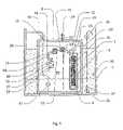
- FIG. 1shows a schematic cross-sectional view of the filtration system according to one embodiment of the invention for operation under suction
- FIG. 2shows a schematic cross-sectional view of the filtration system of FIG. 1 in filtration mode
- FIG. 3shows a schematic cross-sectional view of the filtration system of FIG. 1 in backwash mode
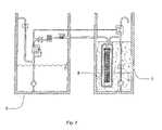
- FIG. 4shows a schematic cross-sectional view of the filtration system according to one embodiment of the invention for operation in on-demand mode
- FIG. 5shows a schematic cross-sectional view of the filtration system of FIG. 4 in filtration mode
- FIG. 6shows a schematic cross-sectional view of the filtration system of FIG. 4 in backwash mode
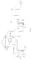
- FIG. 7shows an alternative arrangement for operation in on-demand mode
- FIG. 8shows a further alternative arrangement for operation in on-demand mode
- FIG. 9shows yet a further alternative arrangement for operation in on-demand mode
- FIG. 10shows a schematic cross-sectional view of a further arrangement including a gas supply for gas scouring of the membrane module
- FIG. 11shows a schematic view of a first gravity feed arrangement
- FIG. 12shows a schematic view of a second gravity feed arrangement.
- FIG. 1 of the drawingsone embodiment is shown of the invention where the filtration system is operated under suction.
- the arrangementincludes a feed tank 5 having a smaller filtrate vessel 6 positioned therein.
- the region within the feed tank 5 not occupied by the filtrate vessel 6is partially filled with layers of decomposing and decomposed solid organic waste material to form an aerobic filter bed 7 of the type used in biolytic filtration as described above.
- a further module vessel 8is mounted within the filtrate vessel 6 to form a membrane chamber 9 containing a membrane filtration module 10 .
- a filtrate pump 11is provided on the filtrate side of the membrane filtration module 10 in the filtrate vessel 6 .
- the output side of filtrate pump 11is coupled through a filtrate line 12 for fluid communication with the filtrate collection chamber 13 of the filtration module 10 via a filtrate diaphragm valve 14 and slider valve 15 , respectively.
- the output side of the filtrate pump 11is further coupled to an output line 16 through a non-return valve 17 for outputting treated filtrate from the system.
- the input side of the filtrate pump 11is coupled directly to the filtrate vessel 6 .
- the filtrate diaphragm valve 14has an input port 18 coupled to the filtrate pump 11 and an output port 19 coupled to a port of the slider valve 15 as described below.
- the diaphragm 20is controlled by control line 21 connected to the filtrate-pump-side of the filtrate diaphragm valve 14 via a flow control valve 22 .
- the slider valve 15has first and second ports 23 and 25 coupled to the filtration module 10 and the output port 19 of the filtrate diaphragm valve 14 , respectively.
- a third port 24is coupled directly to the filtrate vessel 6 by an output line 32 .
- a first, bypass position of the valvefluid is fed from the first port 25 via a bypass line 26 to the second port 23 .
- the bypass line 26is closed and fluid is fed from the first port 23 to the third port 24 to allow fluid flow through line 32 .
- the feed side of the filtration module 10is coupled for fluid communication with the filter bed 7 through a feed line 27 connected to a foot valve 28 positioned at or adjacent the base of the filter bed 7 .
- the feed line 27is further connected to a backwash line 29 which opens above the filter bed 7 through a non-return valve 30 for preventing ingress of air.
- the membrane vessel 8is provided with an air vent line 31 connected to the upper portion of the chamber 9 and to the backwash line 29 to vent to the atmosphere via the non-return valve 30 .
- the vent line 31vents directly to the atmosphere via a dedicated manual vent valve (not shown).
- the backwash line 29 and the non-return valve 30also serve to allow backwash fluid to exit onto the filter bed 7 .
- the filtrate vessel 6is similarly provided with an air vent line 33 connected to the upper portion of the vessel and to atmosphere via air vent valve 34 .
- a level switch 35is provided in the filter bed 7 above the level of the foot valve 28 to detect liquid level within the filter bed 7 .
- treated filtratetypically water
- output line 16which reduces the pressure in the filtrate vessel 6 and causes filtrate to be drawn-through the membranes in the membrane module 10 via feed line 27 and the foot valve 28 .
- filtratepasses through the membrane module 10 and filtrate collection chamber 13 and is discharged via the third port 24 in the slider valve 15 into the filtrate vessel 6 via line 32 .
- the level switch 35 in the filter bed 7controls the operation of the filtrate pump 11 and ensures the foot valve 28 remains submerged so as not to draw air into the membrane chamber 9 .
- the filtrate pump 11is stopped and does not restart until the feed liquid level has risen again and triggered a high level switch. While the filtrate pump 11 is off, the liquid level in the filtrate vessel 6 is slowly replenished by the hydraulic level difference between the filtrate in the filtrate vessel 6 and the feed liquid in the filter bed 7 , via the third port 24 of the slider valve 15 and the slider valve output line 32 . As this occurs, air in the filtrate vessel 6 is displaced via the air vent valve 33 at the top of the filtrate vessel 6 and the liquid level rises again to the normal operating level.
- the filtrate diaphragm valve 14(now open as the pressure has been released from the valve with the filtrate pump stopped) allows filtrate to flow back to the membrane module 10 via the slider valve 15 which moves to a bypass position.
- the backflow of filtrateflushes dirt from the surface of the membrane module 10 and from between the membranes and discharges it back on to the filter bed 7 via the backwash line 29 and non-return valve 30 .
- the small flow control valve 22slowly re-pressurises the filtrate diaphragm valve 14 and closes the valve, redirecting the filtrate flow to the output line 16 and opening the slider valve 15 again.
- a further embodiment of the inventionis a demand mode arrangement shown in FIGS. 4 to 6 .
- the filtrate vessel 6 and feed tank 5are provided side by side with the feed tank 5 again partially filled with layers of decomposing and decomposed solid organic waste material to form a filter bed 7 of the type used in biolytic filtration as described above.
- the module vessel 8is mounted within the feed vessel 5 and filter bed 7 to form a membrane chamber 9 containing the membrane filtration module 10 .
- a feed line 27is coupled to a feed pump 36 via a non-return valve 37 .
- the feed pump 36has an inlet 38 positioned adjacent the base of the filter bed 7 .
- the feed line 27is further connected to a backwash line 29 through backwash diaphragm valve 39 .
- a filtrate pump 11is again provided on the filtrate side of the membrane filtration module 10 in the filtrate vessel 6 .
- the output side of filtrate pump 11is coupled for fluid communication with the filtrate collection chamber 13 of the filtration module 10 through a filtrate line 12 via a filtrate diaphragm valve 14 , non-return valve 40 and slider valve 15 , respectively.
- the output side of the filtrate pump 11is further coupled to an output line 16 through a non-return valve 17 for outputting treated filtrate from the system.
- the input side of the filtrate pump 11is coupled directly to the filtrate vessel 6 .
- the backwash diaphragm valve 39has an input port 41 and an output port 42 .
- the diaphragm 43is controlled by control line 44 connected to filtrate line 12 between the filtrate diaphragm valve 14 and the non-return valve 40 .
- a small air bleed line 45is provided between the top of the module vessel 8 and the backwash line 30 .
- a filtrate level switch 46 and feed level switch 35are provided in the filtrate vessel 6 and feed tank 5 respectively to control liquid levels therein.
- the membrane module 10is operated under positive pressure with a feed pump 36 upstream of the membrane module 10 .
- the feed pump 36is running and pushes the feed through the membranes in the membrane module 10 and into the filtrate vessel 6 via the slider valve 15 .
- the bleed line 45 at the top of the membrane vessel 8ensures that any air in the membrane chamber 9 is vented back on to the filter bed 7 .
- the flow through this bleed line 45is small in relation to the forward filtration flow.
- the filtrate pump 11will start and draw filtrate from the filtrate vessel 6 for use.
- filtrate pump 11As the filtrate pump 11 starts, filtrate will flow back to the membrane module 10 via the filtrate diaphragm valve 14 (now open as the bleed control valve has vented), through the slider valve 15 and the membrane module 10 , and discharge via the now open backwash diaphragm valve 39 , back on to the filter bed 7 .
- the duration of the backwashis determined by the selection of the flow control valve back to the filtrate diaphragm valve 14 .
- the filtrate diaphragm valve 14closes, which depressurises the backwash diaphragm valve 39 allowing it to close, and filtrate is again supplied via the filtrate output line 16 .
- FIG. 7shows an alternative arrangement in which the feed tank 5 is remote from the filtrate chamber 6 .
- FIG. 8shows a further arrangement in which the feed tank 5 and the filtrate chamber 6 are remote from one another.
- the module vessel 8is located within the filtrate chamber 6 .
- FIG. 9the feed tank 5 , the filtrate chamber 6 and the module vessel 8 are all provided remote from one another.
- the appropriate arrangement for a particular installationmay be selected based on constraints relating to the space available and maintenance requirements.
- the arrangements shown in FIGS. 7 to 10are operated in a manner analogous to that described in relation to the arrangement shown in FIGS. 4 to 6 .
- FIG. 10shows another embodiment in which the membrane module is located in the feed tank, which is remote from the filtrate chamber.
- a venturi or eductor 49is fitted to the discharge of feed pump.
- the feed inlet 47 to the membrane module 10is moved to the bottom of the module vessel 8 and a membrane module 10 with suitable openings for gas scouring is fitted.
- a modulesuch as that described in U.S. Pat. Nos. 6,156,200, 6,555,005 or U.S. Pat. No. 6,841,070 may be used.
- the gas line 50 supplying the eductor 49is actuated via a gas supply diaphragm valve 55 using the same bleed line 44 arrangement as for the filtrate and backwash diaphragm valves, such that the gas line only opens during the backwash process. This allows a flush of gas, typically air, to occur at the same time as the liquid backwash and result in an improved backwash and solids removal step.
- a small vessel 48 containing chlorine tabletsis inserted in the backwash line of FIG. 1 , between the filtrate diaphragm valve 14 and the slider valve 15 .
- This vesselallows the slow dissolution of chlorine into the liquid in the chlorine vessel.
- the filtrate pump 11starts and backwash occurs, the filtrate that is pushed back through the membrane will contain chlorine. This assists in the backwash process and helps to keep the membrane clean and disinfected.
- the same arrangementmay be applied to chlorinate the filtrate leaving the membrane module 10 in either suction mode ( FIG. 1 ) or demand mode ( FIG. 4 ), by installing the chlorine chamber in the filtrate line leaving the membrane module 10 . In this latter arrangement, all filtrate is chlorinated upon leaving the membrane module before entering the filtrate chamber 6 .
- FIG. 11shows a first gravity feed arrangement in which water to be treated is fed to a feed tank 5 having layers of decomposing and decomposed solid organic waste material to form an aerobic filter bed 7 as described above.
- a feed pump 51pumps water from adjacent the base of the feed tank to a header tank 52 provided above the level of a filtrate chamber 6 containing a module vessel 8 .
- the header tank 52may be located on the ground, with the filtrate chamber underground.
- the header tank 52may be located on a wall of a building 53 .
- Wateris fed to the membrane module 10 located within the module vessel 8 and from there into the filtrate chamber 6 . From the filter chamber, the treated water is pumped for reuse within the building 53 or in a garden. Surplus water may be routed to a storm drain.
- FIG. 12shows a further gravity fed arrangement in which the feed tank 5 with filter bed 7 is located below the level of the building 53 .
- Wateris fed from adjacent the base of the feed tank 5 to a filter chamber 54 located below the level of the feed tank 5 .
- the filter chamber 54includes a carbon filter or other filter, for example for reduction of colour in the water.
- Wateris further fed from adjacent the base of the filter chamber 54 to a filtrate chamber 6 via a module vessel 8 containing a membrane module 10 as described above. From the filtrate chamber, treated water may be drawn for reuse or passed to a storm drain.
- alternate biological treatment componentsare used in place of an aerobic compost bed.
- alternate biological treatment componentsinclude those typically used in post treatment stages such as compositing processes, aerated fixed film processes, and/or mixed liquor type processes with post settling.
Landscapes
- Life Sciences & Earth Sciences (AREA)
- Hydrology & Water Resources (AREA)
- Engineering & Computer Science (AREA)
- Environmental & Geological Engineering (AREA)
- Water Supply & Treatment (AREA)
- Chemical & Material Sciences (AREA)
- Organic Chemistry (AREA)
- Biodiversity & Conservation Biology (AREA)
- Microbiology (AREA)
- Separation Using Semi-Permeable Membranes (AREA)
- Processing Of Solid Wastes (AREA)
Abstract
Description
- a) a biological treatment component;
- b) inlet means for supplying wastewater to said biological treatment component;
- c) a membrane filter device including one or more hollow, permeable membranes with a feed side in fluid communication with said biological treatment component;
- d) pump means coupled to said membrane device and being selectively operable to provide a filtration operation by producing a pressure differential across the walls of said membranes to cause flow of feed liquid from the biological treatment component to the feed side of the membrane walls and withdrawal of filtrate liquid from the filtrate side of said membrane walls.
- a) forming and maintaining an aerobic compost bed;
- b) feeding wastewater onto the aerobic compost bed;
- c) causing said wastewater to filter through the aerobic compost bed;
- d) removing filtered wastewater from the aerobic compost bed;
- e) applying the removed filtered wastewater to a feed side of a membrane filter;
- f) withdrawing treated wastewater from a filtrate side of said membrane filter.
Claims (21)
Applications Claiming Priority (3)
| Application Number | Priority Date | Filing Date | Title |
|---|---|---|---|
| AU2005906191 | 2005-11-08 | ||
| AU2005906191AAU2005906191A0 (en) | 2005-11-08 | Combination membrane/biolytic filtration | |
| PCT/AU2006/001666WO2007053890A1 (en) | 2005-11-08 | 2006-11-08 | Combination membrane/biolytic filtration |
Publications (2)
| Publication Number | Publication Date |
|---|---|
| US20080290025A1 US20080290025A1 (en) | 2008-11-27 |
| US7708887B2true US7708887B2 (en) | 2010-05-04 |
Family
ID=38022889
Family Applications (1)
| Application Number | Title | Priority Date | Filing Date |
|---|---|---|---|
| US12/092,755Expired - Fee RelatedUS7708887B2 (en) | 2005-11-08 | 2006-11-08 | Combination membrane/biolytic filtration |
Country Status (9)
| Country | Link |
|---|---|
| US (1) | US7708887B2 (en) |
| EP (1) | EP1954635A1 (en) |
| JP (1) | JP4902661B2 (en) |
| KR (1) | KR20080075160A (en) |
| CN (1) | CN101304951A (en) |
| CA (1) | CA2626941A1 (en) |
| MY (1) | MY148024A (en) |
| NZ (1) | NZ567585A (en) |
| WO (1) | WO2007053890A1 (en) |
Cited By (32)
| Publication number | Priority date | Publication date | Assignee | Title |
|---|---|---|---|---|
| US20050109692A1 (en)* | 1998-09-25 | 2005-05-26 | Fufang Zha | Apparatus and method for cleaning membrane filtration modules |
| US20080156745A1 (en)* | 2004-09-15 | 2008-07-03 | U.S. Filter Wastewater Group, Inc. | Continuously Variable Aeration |
| US8182687B2 (en) | 2002-06-18 | 2012-05-22 | Siemens Industry, Inc. | Methods of minimising the effect of integrity loss in hollow fibre membrane modules |
| US8268176B2 (en) | 2003-08-29 | 2012-09-18 | Siemens Industry, Inc. | Backwash |
| US8287743B2 (en) | 2007-05-29 | 2012-10-16 | Siemens Industry, Inc. | Membrane cleaning with pulsed airlift pump |
| US8293098B2 (en) | 2006-10-24 | 2012-10-23 | Siemens Industry, Inc. | Infiltration/inflow control for membrane bioreactor |
| US8318028B2 (en) | 2007-04-02 | 2012-11-27 | Siemens Industry, Inc. | Infiltration/inflow control for membrane bioreactor |
| US8382981B2 (en) | 2008-07-24 | 2013-02-26 | Siemens Industry, Inc. | Frame system for membrane filtration modules |
| US8496828B2 (en) | 2004-12-24 | 2013-07-30 | Siemens Industry, Inc. | Cleaning in membrane filtration systems |
| US8506806B2 (en) | 2004-09-14 | 2013-08-13 | Siemens Industry, Inc. | Methods and apparatus for removing solids from a membrane module |
| US8512568B2 (en) | 2001-08-09 | 2013-08-20 | Siemens Industry, Inc. | Method of cleaning membrane modules |
| US8518256B2 (en) | 2001-04-04 | 2013-08-27 | Siemens Industry, Inc. | Membrane module |
| US8652331B2 (en) | 2008-08-20 | 2014-02-18 | Siemens Water Technologies Llc | Membrane system backwash energy efficiency |
| US8758621B2 (en) | 2004-03-26 | 2014-06-24 | Evoqua Water Technologies Llc | Process and apparatus for purifying impure water using microfiltration or ultrafiltration in combination with reverse osmosis |
| US8758622B2 (en) | 2004-12-24 | 2014-06-24 | Evoqua Water Technologies Llc | Simple gas scouring method and apparatus |
| US8790515B2 (en) | 2004-09-07 | 2014-07-29 | Evoqua Water Technologies Llc | Reduction of backwash liquid waste |
| US8808540B2 (en) | 2003-11-14 | 2014-08-19 | Evoqua Water Technologies Llc | Module cleaning method |
| US8858796B2 (en) | 2005-08-22 | 2014-10-14 | Evoqua Water Technologies Llc | Assembly for water filtration using a tube manifold to minimise backwash |
| US8956464B2 (en) | 2009-06-11 | 2015-02-17 | Evoqua Water Technologies Llc | Method of cleaning membranes |
| US9022224B2 (en) | 2010-09-24 | 2015-05-05 | Evoqua Water Technologies Llc | Fluid control manifold for membrane filtration system |
| US9533261B2 (en) | 2012-06-28 | 2017-01-03 | Evoqua Water Technologies Llc | Potting method |
| US9604166B2 (en) | 2011-09-30 | 2017-03-28 | Evoqua Water Technologies Llc | Manifold arrangement |
| US9675938B2 (en) | 2005-04-29 | 2017-06-13 | Evoqua Water Technologies Llc | Chemical clean for membrane filter |
| US9764288B2 (en) | 2007-04-04 | 2017-09-19 | Evoqua Water Technologies Llc | Membrane module protection |
| US9764289B2 (en) | 2012-09-26 | 2017-09-19 | Evoqua Water Technologies Llc | Membrane securement device |
| US9815027B2 (en) | 2012-09-27 | 2017-11-14 | Evoqua Water Technologies Llc | Gas scouring apparatus for immersed membranes |
| US9914097B2 (en) | 2010-04-30 | 2018-03-13 | Evoqua Water Technologies Llc | Fluid flow distribution device |
| US9925499B2 (en) | 2011-09-30 | 2018-03-27 | Evoqua Water Technologies Llc | Isolation valve with seal for end cap of a filtration system |
| US9962865B2 (en) | 2012-09-26 | 2018-05-08 | Evoqua Water Technologies Llc | Membrane potting methods |
| US10322375B2 (en) | 2015-07-14 | 2019-06-18 | Evoqua Water Technologies Llc | Aeration device for filtration system |
| US10427102B2 (en) | 2013-10-02 | 2019-10-01 | Evoqua Water Technologies Llc | Method and device for repairing a membrane filtration module |
| IT202300009627A1 (en)* | 2023-05-12 | 2024-11-12 | Starplast S R L | DEVICE FOR PURIFICATION OF GREY WATER |
Families Citing this family (2)
| Publication number | Priority date | Publication date | Assignee | Title |
|---|---|---|---|---|
| US11053141B2 (en)* | 2013-10-28 | 2021-07-06 | Vestergaard Sa | Water purification device |
| US11485662B2 (en)* | 2018-01-24 | 2022-11-01 | Gemini Science, Llc | Integrated filtration and gas floatation water treatment system and process |
Citations (10)
| Publication number | Priority date | Publication date | Assignee | Title |
|---|---|---|---|---|
| US3472765A (en)* | 1968-06-10 | 1969-10-14 | Dorr Oliver Inc | Membrane separation in biological-reactor systems |
| US5633163A (en)* | 1992-09-14 | 1997-05-27 | Dowmus Pty Ltd | Method for treating wastewater and solid organic waste |
| US5961830A (en)* | 1994-11-18 | 1999-10-05 | Barnett; Kenneth Edward | Wastewater treatment method and plant |
| US6001254A (en)* | 1995-04-14 | 1999-12-14 | Aquasource | Method of operating and monitoring a group of filter membrane modules, and a group of modules implementing the method |
| US6007712A (en)* | 1997-02-28 | 1999-12-28 | Kuraray Co., Ltd. | Waste water treatment apparatus |
| US6383369B2 (en)* | 2000-03-17 | 2002-05-07 | Clint R. Elston | Waste and wastewater treatment and recycling system |
| US20030192825A1 (en) | 2001-12-17 | 2003-10-16 | Industrial Technology Research Institute | Membrane bioreactor using non-woven fabric filtration |
| US20040079701A1 (en) | 2002-10-25 | 2004-04-29 | Industrial Technology Research Institute | Method for treating wastewater/water with membrane bioreactor |
| WO2005100264A2 (en) | 2004-04-06 | 2005-10-27 | Vost Environmental Technologies | Method and apparatus providing improved throughput and operating life of submerged membranes |
| EP1647530A1 (en) | 2004-10-14 | 2006-04-19 | ITT Manufacturing Enterprises, Inc. | Energy-efficient biological treatment with membrane filtration |
Family Cites Families (10)
| Publication number | Priority date | Publication date | Assignee | Title |
|---|---|---|---|---|
| JPS61200892A (en)* | 1985-02-28 | 1986-09-05 | Hitachi Plant Eng & Constr Co Ltd | Apparatus for treating waste water |
| JPH0667518B2 (en)* | 1986-02-26 | 1994-08-31 | オルガノ株式会社 | Aerobic bioreactor |
| JPH0667519B2 (en)* | 1986-06-10 | 1994-08-31 | 清 青嶋 | Method of treating feces, urine, organic sludge, sewage, etc. |
| JP2699108B2 (en)* | 1989-06-08 | 1998-01-19 | 東急建設株式会社 | Sewage treatment method by hollow fiber membrane |
| JPH0829320B2 (en)* | 1992-08-31 | 1996-03-27 | 株式会社東洋製作所 | High-concentration organic wastewater treatment equipment |
| JPH0629690U (en)* | 1992-09-18 | 1994-04-19 | 三菱化工機株式会社 | Organic wastewater treatment equipment |
| JPH0839088A (en)* | 1994-08-02 | 1996-02-13 | Toto Ltd | Purifying tank and operation thereof |
| JPH09225487A (en)* | 1996-02-27 | 1997-09-02 | Ebara Corp | Biological treating device |
| JP2001096299A (en)* | 1999-09-28 | 2001-04-10 | Nkk Corp | Organic wastewater treatment method and treatment apparatus |
| JP2004042008A (en)* | 2002-05-14 | 2004-02-12 | Toshio Hosooka | Treatment method and treatment device for garbage |
- 2006
- 2006-11-08JPJP2008539191Apatent/JP4902661B2/ennot_activeExpired - Fee Related
- 2006-11-08CNCNA2006800416010Apatent/CN101304951A/enactivePending
- 2006-11-08EPEP06804488Apatent/EP1954635A1/enactivePending
- 2006-11-08CACA002626941Apatent/CA2626941A1/ennot_activeAbandoned
- 2006-11-08KRKR20087013705Apatent/KR20080075160A/ennot_activeCeased
- 2006-11-08WOPCT/AU2006/001666patent/WO2007053890A1/enactiveApplication Filing
- 2006-11-08MYMYPI20081485patent/MY148024A/enunknown
- 2006-11-08USUS12/092,755patent/US7708887B2/ennot_activeExpired - Fee Related
- 2006-11-08NZNZ567585Apatent/NZ567585A/ennot_activeIP Right Cessation
Patent Citations (11)
| Publication number | Priority date | Publication date | Assignee | Title |
|---|---|---|---|---|
| US3472765A (en)* | 1968-06-10 | 1969-10-14 | Dorr Oliver Inc | Membrane separation in biological-reactor systems |
| US5633163A (en)* | 1992-09-14 | 1997-05-27 | Dowmus Pty Ltd | Method for treating wastewater and solid organic waste |
| US5961830A (en)* | 1994-11-18 | 1999-10-05 | Barnett; Kenneth Edward | Wastewater treatment method and plant |
| US6001254A (en)* | 1995-04-14 | 1999-12-14 | Aquasource | Method of operating and monitoring a group of filter membrane modules, and a group of modules implementing the method |
| US6007712A (en)* | 1997-02-28 | 1999-12-28 | Kuraray Co., Ltd. | Waste water treatment apparatus |
| US6383369B2 (en)* | 2000-03-17 | 2002-05-07 | Clint R. Elston | Waste and wastewater treatment and recycling system |
| US20030192825A1 (en) | 2001-12-17 | 2003-10-16 | Industrial Technology Research Institute | Membrane bioreactor using non-woven fabric filtration |
| US20040079701A1 (en) | 2002-10-25 | 2004-04-29 | Industrial Technology Research Institute | Method for treating wastewater/water with membrane bioreactor |
| WO2005100264A2 (en) | 2004-04-06 | 2005-10-27 | Vost Environmental Technologies | Method and apparatus providing improved throughput and operating life of submerged membranes |
| EP1647530A1 (en) | 2004-10-14 | 2006-04-19 | ITT Manufacturing Enterprises, Inc. | Energy-efficient biological treatment with membrane filtration |
| US20060081534A1 (en)* | 2004-10-14 | 2006-04-20 | Dimitriou Michael A | Energy-efficient biological treatment with membrane filtration |
Non-Patent Citations (2)
| Title |
|---|
| International Report on Patentability dated Dec. 11, 2007 for Application No. PCT/AU2006/001666. |
| International Search Report dated Jan. 8, 2007 for Application No. PCT/AU2006/001666. |
Cited By (47)
| Publication number | Priority date | Publication date | Assignee | Title |
|---|---|---|---|---|
| US20050109692A1 (en)* | 1998-09-25 | 2005-05-26 | Fufang Zha | Apparatus and method for cleaning membrane filtration modules |
| US8518256B2 (en) | 2001-04-04 | 2013-08-27 | Siemens Industry, Inc. | Membrane module |
| US8512568B2 (en) | 2001-08-09 | 2013-08-20 | Siemens Industry, Inc. | Method of cleaning membrane modules |
| US8182687B2 (en) | 2002-06-18 | 2012-05-22 | Siemens Industry, Inc. | Methods of minimising the effect of integrity loss in hollow fibre membrane modules |
| US8268176B2 (en) | 2003-08-29 | 2012-09-18 | Siemens Industry, Inc. | Backwash |
| US8808540B2 (en) | 2003-11-14 | 2014-08-19 | Evoqua Water Technologies Llc | Module cleaning method |
| US8758621B2 (en) | 2004-03-26 | 2014-06-24 | Evoqua Water Technologies Llc | Process and apparatus for purifying impure water using microfiltration or ultrafiltration in combination with reverse osmosis |
| US8790515B2 (en) | 2004-09-07 | 2014-07-29 | Evoqua Water Technologies Llc | Reduction of backwash liquid waste |
| US8506806B2 (en) | 2004-09-14 | 2013-08-13 | Siemens Industry, Inc. | Methods and apparatus for removing solids from a membrane module |
| US8377305B2 (en) | 2004-09-15 | 2013-02-19 | Siemens Industry, Inc. | Continuously variable aeration |
| US20080156745A1 (en)* | 2004-09-15 | 2008-07-03 | U.S. Filter Wastewater Group, Inc. | Continuously Variable Aeration |
| US8758622B2 (en) | 2004-12-24 | 2014-06-24 | Evoqua Water Technologies Llc | Simple gas scouring method and apparatus |
| US8496828B2 (en) | 2004-12-24 | 2013-07-30 | Siemens Industry, Inc. | Cleaning in membrane filtration systems |
| US9675938B2 (en) | 2005-04-29 | 2017-06-13 | Evoqua Water Technologies Llc | Chemical clean for membrane filter |
| US8858796B2 (en) | 2005-08-22 | 2014-10-14 | Evoqua Water Technologies Llc | Assembly for water filtration using a tube manifold to minimise backwash |
| US8894858B1 (en) | 2005-08-22 | 2014-11-25 | Evoqua Water Technologies Llc | Method and assembly for water filtration using a tube manifold to minimize backwash |
| US8293098B2 (en) | 2006-10-24 | 2012-10-23 | Siemens Industry, Inc. | Infiltration/inflow control for membrane bioreactor |
| US8318028B2 (en) | 2007-04-02 | 2012-11-27 | Siemens Industry, Inc. | Infiltration/inflow control for membrane bioreactor |
| US8623202B2 (en) | 2007-04-02 | 2014-01-07 | Siemens Water Technologies Llc | Infiltration/inflow control for membrane bioreactor |
| US9764288B2 (en) | 2007-04-04 | 2017-09-19 | Evoqua Water Technologies Llc | Membrane module protection |
| US8372276B2 (en) | 2007-05-29 | 2013-02-12 | Siemens Industry, Inc. | Membrane cleaning with pulsed airlift pump |
| US8840783B2 (en) | 2007-05-29 | 2014-09-23 | Evoqua Water Technologies Llc | Water treatment membrane cleaning with pulsed airlift pump |
| US10507431B2 (en) | 2007-05-29 | 2019-12-17 | Evoqua Water Technologies Llc | Membrane cleaning with pulsed airlift pump |
| US9206057B2 (en) | 2007-05-29 | 2015-12-08 | Evoqua Water Technologies Llc | Membrane cleaning with pulsed airlift pump |
| US9573824B2 (en) | 2007-05-29 | 2017-02-21 | Evoqua Water Technologies Llc | Membrane cleaning with pulsed airlift pump |
| US8622222B2 (en) | 2007-05-29 | 2014-01-07 | Siemens Water Technologies Llc | Membrane cleaning with pulsed airlift pump |
| US8287743B2 (en) | 2007-05-29 | 2012-10-16 | Siemens Industry, Inc. | Membrane cleaning with pulsed airlift pump |
| US8382981B2 (en) | 2008-07-24 | 2013-02-26 | Siemens Industry, Inc. | Frame system for membrane filtration modules |
| US9023206B2 (en) | 2008-07-24 | 2015-05-05 | Evoqua Water Technologies Llc | Frame system for membrane filtration modules |
| US8652331B2 (en) | 2008-08-20 | 2014-02-18 | Siemens Water Technologies Llc | Membrane system backwash energy efficiency |
| US8956464B2 (en) | 2009-06-11 | 2015-02-17 | Evoqua Water Technologies Llc | Method of cleaning membranes |
| US10441920B2 (en) | 2010-04-30 | 2019-10-15 | Evoqua Water Technologies Llc | Fluid flow distribution device |
| US9914097B2 (en) | 2010-04-30 | 2018-03-13 | Evoqua Water Technologies Llc | Fluid flow distribution device |
| US9630147B2 (en) | 2010-09-24 | 2017-04-25 | Evoqua Water Technologies Llc | Fluid control manifold for membrane filtration system |
| US9022224B2 (en) | 2010-09-24 | 2015-05-05 | Evoqua Water Technologies Llc | Fluid control manifold for membrane filtration system |
| US9925499B2 (en) | 2011-09-30 | 2018-03-27 | Evoqua Water Technologies Llc | Isolation valve with seal for end cap of a filtration system |
| US9604166B2 (en) | 2011-09-30 | 2017-03-28 | Evoqua Water Technologies Llc | Manifold arrangement |
| US10391432B2 (en) | 2011-09-30 | 2019-08-27 | Evoqua Water Technologies Llc | Manifold arrangement |
| US11065569B2 (en) | 2011-09-30 | 2021-07-20 | Rohm And Haas Electronic Materials Singapore Pte. Ltd. | Manifold arrangement |
| US9533261B2 (en) | 2012-06-28 | 2017-01-03 | Evoqua Water Technologies Llc | Potting method |
| US9764289B2 (en) | 2012-09-26 | 2017-09-19 | Evoqua Water Technologies Llc | Membrane securement device |
| US9962865B2 (en) | 2012-09-26 | 2018-05-08 | Evoqua Water Technologies Llc | Membrane potting methods |
| US9815027B2 (en) | 2012-09-27 | 2017-11-14 | Evoqua Water Technologies Llc | Gas scouring apparatus for immersed membranes |
| US10427102B2 (en) | 2013-10-02 | 2019-10-01 | Evoqua Water Technologies Llc | Method and device for repairing a membrane filtration module |
| US11173453B2 (en) | 2013-10-02 | 2021-11-16 | Rohm And Haas Electronic Materials Singapores | Method and device for repairing a membrane filtration module |
| US10322375B2 (en) | 2015-07-14 | 2019-06-18 | Evoqua Water Technologies Llc | Aeration device for filtration system |
| IT202300009627A1 (en)* | 2023-05-12 | 2024-11-12 | Starplast S R L | DEVICE FOR PURIFICATION OF GREY WATER |
Also Published As
| Publication number | Publication date |
|---|---|
| JP4902661B2 (en) | 2012-03-21 |
| CN101304951A (en) | 2008-11-12 |
| NZ567585A (en) | 2010-02-26 |
| JP2009514666A (en) | 2009-04-09 |
| KR20080075160A (en) | 2008-08-14 |
| WO2007053890A8 (en) | 2007-10-25 |
| US20080290025A1 (en) | 2008-11-27 |
| EP1954635A1 (en) | 2008-08-13 |
| MY148024A (en) | 2013-02-28 |
| WO2007053890A1 (en) | 2007-05-18 |
| CA2626941A1 (en) | 2007-05-18 |
Similar Documents
| Publication | Publication Date | Title |
|---|---|---|
| US7708887B2 (en) | Combination membrane/biolytic filtration | |
| US7276171B2 (en) | Method for cleaning separation membrane | |
| EP2258663A1 (en) | Grey water regeneration system | |
| KR20060080584A (en) | Reflux | |
| CZ301746B6 (en) | Method of deep biological purification of waste water and apparatus to implement the same | |
| JP2013006133A (en) | Liquid treatment apparatus and liquid treatment method | |
| AU2006312995B2 (en) | Combination membrane/biolytic filtration | |
| JP5025672B2 (en) | Membrane separator | |
| CZ296942B6 (en) | Method of biological sewage purification and plant for making the same | |
| JP2008221133A (en) | Wastewater treatment equipment | |
| JP2014172014A (en) | Membrane separation device and membrane separation method | |
| JP5423184B2 (en) | Filtration membrane module cleaning method and cleaning apparatus | |
| JP4397360B2 (en) | Septic tank | |
| JP2005163411A (en) | Circulating flush toilet system | |
| JP4557851B2 (en) | Anaerobic water treatment device | |
| JP4589203B2 (en) | Liquid waste treatment equipment for ship life | |
| JPH10235400A (en) | Sludge treatment method and apparatus | |
| JP3479632B2 (en) | Wastewater treatment equipment | |
| JP4335193B2 (en) | Method and apparatus for treating organic wastewater | |
| JP2006007221A (en) | Anaerobic water treatment apparatus | |
| JP3106063B2 (en) | Membrane separation equipment | |
| JP2025023450A (en) | Purification system and purification method | |
| CZ20011095A3 (en) | Waste water treatment process and plant for making the same | |
| JPH1015552A (en) | Membrane separation sewage treatment apparatus | |
| JPH1157763A (en) | Septic tank |
Legal Events
| Date | Code | Title | Description |
|---|---|---|---|
| AS | Assignment | Owner name:SIEMENS WATER TECHNOLOGIES CORP., MASSACHUSETTS Free format text:ASSIGNMENT OF ASSIGNORS INTEREST;ASSIGNORS:JOHNSON, WARREN THOMAS;BILTOFT, BRUCE GREGORY;CAMERON, DEAN OSMAN;REEL/FRAME:020953/0755;SIGNING DATES FROM 20061204 TO 20061209 Owner name:SIEMENS WATER TECHNOLOGIES CORP.,MASSACHUSETTS Free format text:ASSIGNMENT OF ASSIGNORS INTEREST;ASSIGNORS:JOHNSON, WARREN THOMAS;BILTOFT, BRUCE GREGORY;CAMERON, DEAN OSMAN;SIGNING DATES FROM 20061204 TO 20061209;REEL/FRAME:020953/0755 | |
| AS | Assignment | Owner name:SIEMENS WATER TECHNOLOGIES HOLDING CORP., PENNSYLV Free format text:MERGER;ASSIGNOR:SIEMENS WATER TECHNOLOGIES CORP.;REEL/FRAME:026106/0467 Effective date:20110401 | |
| AS | Assignment | Owner name:SIEMENS INDUSTRY, INC., GEORGIA Free format text:MERGER;ASSIGNOR:SIEMENS WATER TECHNOLOGIES HOLDING CORP.;REEL/FRAME:026138/0593 Effective date:20110401 | |
| FPAY | Fee payment | Year of fee payment:4 | |
| AS | Assignment | Owner name:SIEMENS WATER TECHNOLOGIES LLC, GEORGIA Free format text:ASSIGNMENT OF ASSIGNORS INTEREST;ASSIGNOR:SIEMENS INDUSTRY, INC.;REEL/FRAME:031896/0256 Effective date:20130731 | |
| AS | Assignment | Owner name:CREDIT SUISSE AG, CAYMAN ISLANDS BRANCH, AS COLLAT Free format text:INTELLECTUAL PROPERTY SECURITY AGREEMENT (SECOND LIEN);ASSIGNORS:WTG HOLDINGS III CORP.;WTG HOLDINGS II CORP.;SIEMENS TREATED WATER OUTSOURCING CORP.;AND OTHERS;REEL/FRAME:032126/0430 Effective date:20140115 Owner name:CREDIT SUISSE AG, CAYMAN ISLANDS BRANCH, AS COLLAT Free format text:INTELLECTUAL PROPERTY SECURITY AGREEMENT (FIRST LIEN);ASSIGNORS:WTG HOLDINGS III CORP.;WTG HOLDINGS II CORP.;SIEMENS TREATED WATER OUTSOURCING CORP.;AND OTHERS;REEL/FRAME:032126/0487 Effective date:20140115 | |
| AS | Assignment | Owner name:EVOQUA WATER TECHNOLOGIES LLC, GEORGIA Free format text:CHANGE OF NAME;ASSIGNOR:SIEMENS WATER TECHNOLOGIES LLC;REEL/FRAME:032174/0282 Effective date:20140116 | |
| FEPP | Fee payment procedure | Free format text:MAINTENANCE FEE REMINDER MAILED (ORIGINAL EVENT CODE: REM.) | |
| LAPS | Lapse for failure to pay maintenance fees | Free format text:PATENT EXPIRED FOR FAILURE TO PAY MAINTENANCE FEES (ORIGINAL EVENT CODE: EXP.) | |
| STCH | Information on status: patent discontinuation | Free format text:PATENT EXPIRED DUE TO NONPAYMENT OF MAINTENANCE FEES UNDER 37 CFR 1.362 | |
| FP | Expired due to failure to pay maintenance fee | Effective date:20180504 | |
| AS | Assignment | Owner name:SIEMENS WATER TECHNOLOGIES LLC, GEORGIA Free format text:RELEASE OF SECURITY INTEREST (REEL/FRAME 032126/0430);ASSIGNOR:CREDIT SUISSE AG, CAYMAN ISLANDS BRANCH, AS COLLATERAL AGENT;REEL/FRAME:055845/0311 Effective date:20210401 Owner name:SIEMENS WATER TECHNOLOGIES LLC, GEORGIA Free format text:RELEASE OF SECURITY INTEREST (REEL/FRAME 032126/0487);ASSIGNOR:CREDIT SUISSE AG, CAYMAN ISLANDS BRANCH, AS COLLATERAL AGENT;REEL/FRAME:055845/0245 Effective date:20210401 |