US7708754B2 - Stretch resistant embolic coil delivery system with mechanical release mechanism - Google Patents
Stretch resistant embolic coil delivery system with mechanical release mechanismDownload PDFInfo
- Publication number
- US7708754B2 US7708754B2US11/755,364US75536407AUS7708754B2US 7708754 B2US7708754 B2US 7708754B2US 75536407 AUS75536407 AUS 75536407AUS 7708754 B2US7708754 B2US 7708754B2
- Authority
- US
- United States
- Prior art keywords
- kicker
- distal end
- pusher
- extending
- embolic device
- Prior art date
- Legal status (The legal status is an assumption and is not a legal conclusion. Google has not performed a legal analysis and makes no representation as to the accuracy of the status listed.)
- Active, expires
Links
Images


Classifications
- A—HUMAN NECESSITIES
- A61—MEDICAL OR VETERINARY SCIENCE; HYGIENE
- A61B—DIAGNOSIS; SURGERY; IDENTIFICATION
- A61B17/00—Surgical instruments, devices or methods
- A61B17/12—Surgical instruments, devices or methods for ligaturing or otherwise compressing tubular parts of the body, e.g. blood vessels or umbilical cord
- A61B17/12022—Occluding by internal devices, e.g. balloons or releasable wires
- A61B17/12099—Occluding by internal devices, e.g. balloons or releasable wires characterised by the location of the occluder
- A61B17/12109—Occluding by internal devices, e.g. balloons or releasable wires characterised by the location of the occluder in a blood vessel
- A61B17/12113—Occluding by internal devices, e.g. balloons or releasable wires characterised by the location of the occluder in a blood vessel within an aneurysm
- A—HUMAN NECESSITIES
- A61—MEDICAL OR VETERINARY SCIENCE; HYGIENE
- A61B—DIAGNOSIS; SURGERY; IDENTIFICATION
- A61B17/00—Surgical instruments, devices or methods
- A61B17/12—Surgical instruments, devices or methods for ligaturing or otherwise compressing tubular parts of the body, e.g. blood vessels or umbilical cord
- A61B17/12022—Occluding by internal devices, e.g. balloons or releasable wires
- A61B17/12131—Occluding by internal devices, e.g. balloons or releasable wires characterised by the type of occluding device
- A61B17/1214—Coils or wires
- A61B17/12154—Coils or wires having stretch limiting means
- A—HUMAN NECESSITIES
- A61—MEDICAL OR VETERINARY SCIENCE; HYGIENE
- A61B—DIAGNOSIS; SURGERY; IDENTIFICATION
- A61B17/00—Surgical instruments, devices or methods
- A61B2017/00477—Coupling
- A—HUMAN NECESSITIES
- A61—MEDICAL OR VETERINARY SCIENCE; HYGIENE
- A61B—DIAGNOSIS; SURGERY; IDENTIFICATION
- A61B17/00—Surgical instruments, devices or methods
- A61B17/12—Surgical instruments, devices or methods for ligaturing or otherwise compressing tubular parts of the body, e.g. blood vessels or umbilical cord
- A61B17/12022—Occluding by internal devices, e.g. balloons or releasable wires
- A61B2017/1205—Introduction devices
- A61B2017/12054—Details concerning the detachment of the occluding device from the introduction device
Definitions
- the present inventionrelates to a medical device for placing a stretch resistant embolic device at a predetermined site within a vessel of the human body, and more particularly, relates to a catheter-based deployment system for delivering an embolic device.
- This deviceis particularly suited to transport an embolic device, such as a stretch resistant embolic coil, through the tortuous vasculature of the human brain to a selected site within the vessel or within an aneurysm.
- Coils which are placed in vesselsmay take the form of helically wound coils, or alternatively, may take the form of randomly wound coils, coils wound within coils or other such coil configurations. Examples of various coil configurations are disclosed in U.S. Pat. No. 5,334,210, entitled, “Vascular Occlusion Assembly” and U.S. Pat. No. 5,382,259 entitled, “Vasoocclusion Coil with Attached Tubular Woven or Braided Fibrous Covering.” Embolic coils are generally formed of a radiopaque metallic material, such as platinum, gold, tungsten, or alloys of these metals. Often, several coils are placed at a given location to occlude the flow of blood through the vessel, or aneurysm, by promoting thrombus formation at the particular site.
- a radiopaque metallic materialsuch as platinum, gold, tungsten, or alloys of these metals.
- embolic coilshave been placed within the distal end of a catheter. When the distal end of the catheter is properly positioned, the coil may then be pushed out of the end of the catheter with a pusher member to release the coil at the desired location. This procedure for placement of an embolic coil is conducted under fluoroscopic visualization such that the movement of the coil through the vasculature of the body may be monitored and the coil placed at the desired location.
- Another procedureinvolves the use of glue or solder for attaching the coil to a guidewire, which in turn, is placed within a flexible catheter for positioning the coil within the vessel at a preselected position. Once the coil is in the desired position, the coil is held in position by the catheter and the guidewire is pulled proximally to thereby cause the coil to become detached from the guidewire and released from the catheter.
- a coil positioning systemis disclosed in U.S. Pat. No. 5,263,964 entitled, “Coaxial Traction Detachment Apparatus and Method.”
- Still another coil positioning procedureis that of having a catheter with a socket at the distal end of the catheter for retaining a ball which is, in turn, bonded to the proximal end of the coil.
- the ballwhich is generally larger in diameter than the outside diameter of the coil, is placed in the socket within the lumen at the distal end of the catheter and the catheter is then moved into a vessel in order to place the coil at a desired position.
- a pusher wire with a piston at the end thereofis pushed distally from the proximal end of the catheter to push the ball out of the socket in order to release the coil at the desired position.
- Another procedure for placing an embolic coil within a vesselis that of using a heat releasable adhesive bond for retaining the coil at the distal end of the catheter.
- One such systemuses laser energy transmitted through a fiber optic cable to apply heat to the adhesive bond in order to release the coil from the end of the catheter.
- Such a procedureis disclosed in U.S. Pat. No. 5,108,407, entitled “Method and Apparatus for Placement of an Embolic Coil.”
- Yet another coil deployment systemincorporates a catheter having a lumen throughout the length of the catheter and a distal tip for retaining the coil for positioning the coil at a preselected site.
- the distal tip of the catheteris formed of a material which exhibits the characteristic that when the lumen of the catheter is pressurized the distal tip expands radially to release the coil at the preselected site.
- Still another coil deployment systemincorporates an interlocking mechanism on the coil.
- the interlocking end on the embolic coilcouples with a similar interlocking mechanism on a pusher assembly.
- a control wirewhich extends through the locking mechanism secures the coil to the pusher assembly.
- the pusher assembly and embolic coilare initially disposed within the lumen of a catheter. When the embolic coil is pushed out of the end of the catheter for placement, the control wire is retracted and the coil disengages from the pusher assembly.
- Yet another coil deployment systemincorporates an embolic device detachably mounted on the distal portion of a pusher member and held in place with a connector thread or fiber.
- the fiberpasses through a cutter member that may be activated to cut the connector fiber. Once the connector fiber is cut, the embolic device is released.
- Such a deployment systemis disclosed in Published U.S. Patent Application No. 2002/0165569, entitled, “Intravascular Device Deployment Mechanism Incorporating Mechanical Detachment.”
- Still another coil deployment systemincorporates an embolic device with a stretch resistant member therethrough.
- the distal end of the stretch resistant memberattaches to the embolic coil and the proximal end of the stretch resistant member is detachably mounted on the pusher member through various means such as adhesive, or by a connector fiber adhered to or tied to the pusher member, and is detachable by the application of heat.
- Such a deployment systemis disclosed in Published U.S. Patent Application No. 2004/0034363, entitled, “Stretch Resistant Therapeutic Device.”
- Still another coil deployment systemincorporates a pusher wire with a stiff wavy-shaped end segment which is coupled to the embolic coil and is placed in the lumen of the catheter. The coil is advanced through the catheter until it reaches a predetermined site in the vessel at which time the pusher wire is retracted and the embolic coil is released.
- a pusher wirewith a stiff wavy-shaped end segment which is coupled to the embolic coil and is placed in the lumen of the catheter.
- the coilis advanced through the catheter until it reaches a predetermined site in the vessel at which time the pusher wire is retracted and the embolic coil is released.
- Such a systemis disclosed in U.S. Pat. No. 6,203,547, entitled, “Vaso-occlusion Apparatus Having a Manipulable Mechanical Detachment Joint and a Method for Using the Apparatus.”
- a still further embolic device deployment system for placement of an embolic device, or coilincludes a delivery catheter and a flexible pusher member.
- the embolic deviceis retained by an interlocking mechanism which includes a detachment member which extends through an aperture in an engagement member.
- the engagement memberengages a ring on the embolic device.
- the detachment memberis withdrawn from the aperture, the embolic device is released.
- One such deployment systemis disclosed in Published U.S. Patent Application No. 2006/0276823, entitled, “Embolic Coil Delivery System with Mechanical Release Mechanism,” and assigned to the same assignee as the present application.
- the present inventionis directed toward a vascular occlusive embolic device deployment system for use in placing an embolic device at a predetermined site within a vessel which includes an elongated flexible catheter, an elongated pusher member having a lumen extending therethrough and being slidably disposed within the lumen of the catheter.
- the embolic devicetakes the form of an embolic coil defining a central lumen extending between the proximal and distal ends of the coil and having a retaining ring disposed on the proximal end of the coil.
- An engagement memberpreferably having a generally L-shaped configuration, is fixedly attached to the distal end of the pusher member and includes an aperture extending through the distal end thereof.
- the engagement memberextends through the retaining ring of the embolic device.
- the deployment systemincludes a kicker member which takes the form of an elongated projection which may or may not include an aperture extending therethrough, extending from the distal end of the pusher member and exhibits the characteristic of being normally biased parallel to the central axis of the lumen of the pusher member and is deflected in a direction which when it contacts the retaining ring will tend to cause the retaining ring of the embolic device to be lifted off of the engagement member.
- the deployment systemincludes an elongated detachment member which extends from the proximal end of the pusher member, through the lumen of the pusher member and through the aperture of the engagement member such that when the detachment member is pulled proximally the distal end of the detachment member is withdrawn from the aperture of the engagement member to thereby release the embolic device.
- the embolic devicetakes the form of an embolic coil having a fiber such as a platinum wire extending between the distal end of the coil and the retaining ring.
- a deployment systemfor use in placing an embolic device at a predetermined site within a vessel which includes an elongated flexible catheter, an elongated pusher member being slidably disposed within the lumen of the catheter.
- the embolic devicetakes the form of an embolic coil defining a central lumen extending between the proximal and distal ends of the coil.
- a stretch resistant memberhaving first and second ends in which the first end of the stretch resistant member is attached to the distal section of the coil and the second end of the stretch resistant member is attached to a retaining ring.
- An engagement memberpreferably having an L-shaped configuration, is fixedly attached to the distal end of the pusher member and includes an aperture extending through the distal end thereof.
- the engagement memberextends through the retaining ring of the stretch-resistant embolic device.
- the deployment systemincludes a kicker member which takes the form of an elongated projection which may or may not include an aperture extending therethrough, extending from the distal end of the pusher member and exhibits the characteristic of being normally biased parallel to the central axis of the lumen of the pusher member and is deflected in a direction which when it contacts the retaining ring will tend to cause the retaining ring of the embolic device to be lifted off of the engagement member.
- the deployment systemincludes an elongated detachment member which extends from the proximal end of the catheter through the lumen of the catheter and through the aperture of the engagement member such that when the detachment member is pulled proximally the distal end of the detachment member is withdrawn from the aperture of the engagement member to thereby release the embolic device.
- the second end of the stretch-resistant memberis attached to the proximal section of the coil, as opposed to the retaining ring, to prevent the coil from stretching, and the proximal end of the coil is attached to the retaining ring.
- the engagement memberis of an L-shaped configuration and one of the legs is attached to the pusher member and the other leg extends through the retaining ring.
- the aperture of the engagement memberextends through the leg which extends through the retaining ring such that when the detachment member extends through the retaining ring of the embolic device such that the embolic device is interlocked onto the engagement member until the detachment member is withdrawn from the aperture.
- the aperture of the retaining ringhas a central axis which extends generally at a right angle to the central axis of the retaining ring.
- the embolic devicetakes the form of a helically wound embolic coil having a central axis which extends at a right angle to the central axis of the aperture of the retaining ring.
- the stretch resistant memberis attached to and extends from a distal section to a proximal section of the helically wound coil.
- the vascular embolic device deployment systempreferably includes a retaining clamp mounted on the proximal end of the pusher member, and the detachment member extends from a position proximal of the retaining clamp and through a lumen in the clamp in order that the detachment member may be clamped in a fixed position prior to the release of the embolic device. Upon release of the clamp, the detachment member may be withdrawn from the aperture of the engagement member to thereby release the embolic device.
- a deployment systemfor delivering an embolic device to a target location of a body vessel.
- the deployment systemincludes an elongated flexible deployment catheter and an elongated pusher member slidably disposed within a lumen of the deployment catheter.
- An engagement memberextends from the distal end of the pusher member and has an aperture extending through a distal end thereof. A portion of the engagement member extends through the retaining ring of an embolic device.
- Also extending from the distal end of the pusher memberis a kicker member deflected in a direction toward a central axis of a lumen of the pusher member for engagement with the retaining ring.
- the kicker memberis comprised of a shape memory material in a martensitic state at room temperature and automatically movable to a configuration substantially parallel to the central axis of the lumen of the pusher member at a transformation temperature greater than room temperature to lift the retaining ring of the embolic device off of the engagement member.
- An elongated detachment memberextends from a position proximal to the proximal end of the pusher member, through the lumen of the pusher member and through the aperture of the engagement member such that when the detachment member is pulled proximally a distal end of the detachment member is withdrawn from the aperture of the engagement member and the kicker member lifts the retaining ring of the embolic device off of the engagement member to thereby release the embolic device from the pusher member.
- a method of connecting an embolic device to a deployment systemincludes a step of providing a tubular member comprised of a shape memory material and having a proximal end and a distal end.
- a kicker member and an engagement memberare formed at the distal end of the tubular member and are substantially parallel to a central axis of the tubular member.
- An elongated pusher memberis provided and secured to the proximal end of the tubular member. The engagement member and the kicker member are moved to a deflected configuration toward the central axis of the tubular member.
- An embolic deviceis provided and a retaining ring of the embolic device is positioned against the kicker member, with a portion of an aperture of the engagement member passing through the retaining ring.
- a detachment member passing through a lumen of the pusher memberis passed through the aperture of the engagement member to releasably secure the embolic device to the pusher member.
- a component of a deployment system for delivering an embolic device to a target location of a body vesselincludes an elongated pusher member and an engagement member extending from the distal end of the pusher member, with an aperture extending through a distal end of the engagement member.
- a kicker memberis also provided, with a pair of arms extending away from the distal end of the pusher member in a direction away from a central axis of the lumen of the pusher member.
- a proximal crossbarextends between and connects distal ends of the arms.
- a pair of extensionsare generally aligned with the arms and extend distally away from the proximal crossbar.
- the distal ends of the extensionsare connected by a distal crossbar.
- the kicker memberis movable toward the central axis of the lumen of the pusher member to a deflected configuration to cooperate with the engagement member to releasably secure an embolic device to the pusher member.
- FIG. 1is an enlarged, partially sectional view of an embodiment of an embolic device deployment system in accordance with the present invention
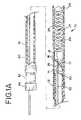
- FIG. 1Ais an enlarged, partially sectional view of a second embodiment of an embolic device deployment system in accordance with the present invention
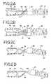
- FIGS. 2A , 2 B, 2 C, and 2 Dare enlarged, sectional views, illustrating in more detail the coil deployment system of FIG. 1A ;
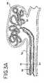
- FIGS. 3 , 3 A, 3 B, and 3 Care enlarged, sectional views of the coil deployment system shown in FIG. 1A illustrating the sequential steps in the advancement of the embolic device, removal of a detachment member, and release of the embolic device;
- FIG. 4Ais a side elevational view of a tubular member which may be incorporated into an embolic device deployment system
- FIG. 4Bis a perspective view of the tubular member of FIG. 4A ;
- FIG. 5Ais a side elevational view and 5 B is a perspective view, each showing the tubular member of FIG. 4A with an engagement member thereof in a deflected configuration;
- FIG. 6is a side elevational of the tubular member of FIGS. 5A and 5B , with a kicker member thereof in a deflected condition;
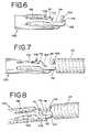
- FIG. 7is a side elevational view of the tubular member of FIG. 6 , with an embolic device positioned on the kicker member;
- FIG. 8is a perspective view of the tubular member of FIG. 7 , with an embolic device secured thereto;
- FIG. 9is a top plan view of the tubular member and the embolic device of FIG. 8 ;
- FIG. 10Ais a perspective view of a proximal portion of an embolic device having an alternative embodiment of a headpiece suitable for use with the tubular member of FIGS. 4A to 9 ;
- FIG. 10Bis a top plan view of the embolic device portion of FIG. 10A ;
- FIG. 10Cis a side elevational view of the embolic device portion of FIG. 10A .
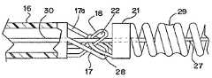
- FIG. 1generally illustrates one embodiment of a vascular occlusive embolic device deployment system 10 which includes a sheath introducer 12 having a lumen 14 extending therethrough and having an elongated pusher member 16 slidably disposed within the lumen 14 of the sheath introducer 12 .
- An elongated engagement member 18extends distally from the pusher member 16 and has an aperture (to be described hereinafter) extending through the distal end thereof.
- the engagement member 18is preferably formed from a distal section of the wall and of the pusher member 16 but may be formed as a separate member attached to the distal end of the pusher member 16 .
- the deployment system 10also includes an embolic device 23 , which as illustrated, preferably takes the form of a helically wound embolic coil, which is disposed in the distal section of the sheath introducer 12 . While the embolic device as illustrated is shown as a helically wound coil various other types of embolic devices, such as filaments, braids, foams, expandable meshes and stents, could be delivered using the present deployment system and various other coil configurations could be delivered using this system.
- a weld, or solder, bead 24is formed at the distal end of the embolic device 23 to provide an atraumatic tip for the embolic device.
- a stretch-resistant member 25which preferably takes the form of a platinum wire, is attached to the distal bead 24 and extends proximally through the central lumen of the coil. While the stretch-resistant member preferably takes the form of a platinum wire, other materials or composites such as polymers, metals and ceramics, having a low elongation relative to the coil elongation may also be suitable. Alternatively, the distal end of the stretch-resistant member could be attached to the coil at a more proximal location in the distal section of the coil.
- a headpiece 21which takes the form of a cylindrical member is disposed on the proximal end of the embolic device 23 .
- the headpiece 21includes a retaining ring 28 which extends proximally from the cylindrical shaped headpiece. The proximal end of the stretch resistant member is then attached to the distal edge of the headpiece 21 .
- the retaining ring 28has a central axis which extends at right angles to the central axis of the sheath introducer 12 and also extends at right angles to the central axis of the helically wound embolic coil.
- FIG. 1Aillustrates another variation of the stretch-resistant embolic device 23 in which the distal end of a stretch-resistant member 27 is attached to the bead 24 at the distal end of the coil and the proximal end of the stretch-resistant member is attached to the turns in the proximal section of the coil by use of a weld, or solder, bead 29 .
- the engagement member 18is of a generally L-shaped configuration and extends through the retaining ring 28 .
- An elongated detachment member 30extends from the proximal end of the deployment system 10 and through a lumen in the pusher member 16 and then through the aperture 22 ( FIG. 2A ) of the engagement member 18 and serves the function of interlocking the embolic device 23 to the pusher member 16 until such time as the detachment member 30 is withdrawn proximally.
- an elongated kicker member 17extends distally from the pusher member 16 and is preferably formed from a distal section of the wall of the pusher member, i.e., cut from the wall of the pusher member as an integral portion of the pusher member, but may also be formed as a separate member attached to the distal end of the pusher member.
- the kicker member 17preferably has an aperture 17 a which extends therethrough as shown in FIG. 2B .
- the kicker member 17may be formed without an aperture.
- the kicker membertakes the form of an elongated projection extending from the distal end of the pusher member 16 .
- the elongated kicker membermay be formed from the wall of the pusher member or may be formed as a separate member attached to the distal end of the pusher member 16 .
- the kicker memberis normally biased in a direction parallel to the central axis of the lumen of the pusher member but is deflected from the wall of the pusher member in a direction toward the central axis of the lumen of the pusher member when the pusher member is engaged with embolic device 23 .
- the kicker memberis normally biased in a direction which tends to lift the retaining ring 28 off of the engagement member 18 but is prevented from doing so unless the elongated detachment rod 30 is withdrawn from the aperture 22 of the engagement member 18 .
- the detachment member 30preferably takes the form of a small diameter elongate filament, however, other forms such as wires or tubular structures are also suitable. While the detachment member 30 is preferably formed of nitinol, other metals and materials such as, stainless steel, PTFE, nylon, ceramic or glass fiber and composites may also be suitable.
- a Tuohy-Borst type of clamp 32is mounted on the proximal end of the pusher member 16 and when tightened onto the detachment member 30 serves to prevent movement of the detachment member until such time as the clamping cap 34 is loosened to release the grip onto this member.
- FIGS. 2A and 2Billustrate the interlocking arrangement between the embolic device 23 and the pusher member 16 as shown in FIG. 1A , however, these figures illustrate the operation of the deployment system once the pusher member 16 has been moved distally to a position so that the distal end of the pusher member 16 extends slightly out of the distal end of the sheath introducer 12 or a delivery catheter thereby exposing the embolic device 23 .
- the detachment member 30may be pulled proximally to withdraw the detachment member from the aperture 22 of the engagement member 18 to thereby cause the engagement member to disengage from the retaining ring 28 of the embolic device thereby releasing the embolic device 23 at a preselected position.
- the kicker member 17serves to ensure the release of the embolic device 23 by applying a force to the retaining ring 28 to lift the retaining ring 28 from the engagement member 18 .
- the detachment sequence described above and illustrated in FIGS. 2A through 2Dmay be executed while the embolic device 23 is still within the lumen of sheath introducer 12 or a delivery catheter.
- the embolic devicemay be placed at a desired location within a vessel, or within an aneurysm, with the configuration of the device deployment system as shown in FIGS. 2A and 2B . If it is determined that the embolic device is improperly positioned, the embolic device 23 may then be withdrawn from that location and placed at another location, or even removed from the body by first withdrawing the pusher member 16 and the embolic device totally back into the delivery catheter. Once the embolic device has been entirely withdrawn back into the delivery catheter, the catheter may then be moved to a more desirable location and the embolic device may then be released at the new location. With the addition of the stretch resistant member 27 , the embolic device may be withdrawn without concern that the coil will stretch and become very difficult to remove.
- FIGS. 3 , 3 A and 3 Bgenerally illustrate the sequence of placing an embolic device, such as a helical wound coil into an aneurysm 36 which extends from a vessel wall 38 .
- FIG. 3illustrates the vascular occlusive embolic device deployment system 10 in the same configuration as shown in FIG. 1A after the pusher member and associated embolic device have been inserted into a delivery catheter 35 and advanced into a position for deployment of the embolic device 23 , shown as a helical embolic coil, into the aneurysm 36 .
- FIG. 3Aillustrates the deployment device having a configuration similar to FIG.
- the pusher membermay be withdrawn thereby withdrawing the embolic device back into the delivery catheter 35 for repositioning to a different location, or alternatively, to remove the embolic coil entirely from the body.
- FIG. 3Billustrates the deployment device after the detachment member 30 has been removed from the engagement member 18 thereby releasing the embolic device within the aneurysm 36
- FIG. 3Cillustrates the deployment device after the pusher member 16 has been withdrawn back into the delivery catheter 35 at the completion of the procedure or alternatively in order to insert a second coil through the delivery catheter 35 and into the same aneurysm.
- the kicker member and/or the engagement membermay be comprised of a material having shape memory properties.
- the kicker member, the engagement member, the embolic device, and the other components of the deployment systemare otherwise provided in accordance with the foregoing description of the embodiments of FIGS. 1 to 3C , except as will be described herein. Deployment systems incorporating this aspect of the present invention will be described herein with reference to FIGS. 4A to 9 .
- Materials having shape memory propertiesare characterized by the ability to be deformed and thereafter automatically return to a default configuration upon application of an outside stimulus. It may be advantageous to provide a kicker member and/or an engagement member comprised of a heat-activated shape memory material, i.e., a material adapted to automatically return to a default configuration by application of heat.
- Providing a kicker member and/or an engagement member comprised of a shape memory materialmay be achieved by any of a number of methods, such as by providing a hollow tubular member 100 comprised of a shape memory material.
- the tubular member 100is shaped to form a kicker member 102 and an engagement member 104 .
- the kicker member 102 and the engagement member 104may be shaped by any of a number of methods, such as a laser cutting operation.
- the kicker member 102 and the engagement member 104may take any of a number of forms, including the configuration described herein with regard to the embodiments of FIGS. 1 to 3C .
- the kicker member 102 and the engagement member 104may have the configuration illustrated in FIGS.
- the “as formed” or initial configuration of the kicker member 102 and the engagement member 104has them extending substantially parallel to a central axis of the tubular member 100 , which is typical if they are shaped by laser cutting the tubular member 100 .
- the tubular member 100may be processed to impart particular performance characteristics to it.
- itmay be advantageous to impart a preselected martensite-to-austenite transformation temperature to the shape memory material.
- the tubular member 100may be treated to impart a martensite-to-austenite transformation temperature that is between room temperature and human body temperature, more advantageously being closer to human body temperature than room temperature, and most advantageously being slightly below human body temperature for reasons which will be described in greater detail herein.
- the various factors affecting the transformation temperatures of a shape memory materialare well-known to those of ordinary skill in the art, and any of a number of procedures may be employed without departing from the scope of the present invention.
- Heat treatmentis one method of processing a shape memory material and manufacturing, assembly, and deployment processes will be described herein with reference to a heat-activated shape memory material processed by a heat treatment operation, but the methods and apparatus described herein are merely illustrative.
- the proximal end of the tubular member 100is secured to the distal end of a pusher member 16 , typically with the outer and inner diameters of the two being substantially the same and the central axes thereof being aligned with each other.
- the particular method of securing the tubular member 100 to the pusher member 16may vary according to the nature of the shape memory material and the material composition of the pusher member 16 .
- the pusher member 16is threaded at its distal end and the tubular member 100 has a mating thread at its proximal end and the two are joined by a rotational threading operation.
- a force fit approachalso is available, typically accompanied by relative twisting motion between the pusher member and the tubular member.
- the kicker member 102 and the engagement member 104are typically subjected to a reshaping stage to bring them to the configuration of FIG. 6 .
- the temperature of the tubular member 100may be reduced to bring it to a martensitic state, if not already at such a state during the foregoing joinder stage. It may be advantageous for the austenite-to-martensite transformation temperature of the tubular member 100 to be less than human body temperature and greater than room temperature or the temperature at which the deployment system is to be assembled. By such an arrangement, the kicker member 102 and the engagement member 104 are in a martensitic state during assembly and can be easily deformed to the deflected configuration of FIG. 6 .
- the engagement member 104is reshaped by moving it to the deflected configuration of FIGS. 5A and 5B , at which the engagement member 104 is bent toward the common central axis of the tubular member 100 and the pusher member 16 .
- Thisis typically a substantial deformation (a nearly 90° deformation in the embodiment of FIGS. 5A and 5B ), which is generally sufficient to place the engagement member 104 in a state of plastic deformation which the shape memory property of the tubular member 100 cannot overcome, even at temperatures above the martensite-to-austenite transformation temperature.
- the engagement member 104will remain in the deflected configuration of FIGS. 5A and 5B , performing substantially identically to the engagement member 18 of FIGS. 1 to 3C during use of the deployment system.
- the kicker member 102is reshaped by moving it to the deflected configuration of FIG. 6 , in which the kicker member 102 is bent toward the common central axis of the tubular member 100 and the pusher member 16 .
- Thisis a relatively minor deformation, which places the kicker member 102 in a state of elastic deformation which the shape memory property of the tubular member 100 can overcome at temperatures above the martensite-to-austenite transformation temperature.
- Moving the kicker member 102 to the deflected configuration of FIG. 6is typically achieved by pressing on it with the retaining ring 28 of an embolic device 23 , as shown in FIG. 7 .
- the detachment member 30is passed through the aperture 106 of the engagement member 104 to releasably secure the embolic device 23 to the deployment system.
- a deployment system incorporating at least a kicker member comprised of a shape memory materialwill operate generally according to the foregoing description of the embodiments of FIGS. 1 to 3C .
- the kicker member 102moving away from the engagement member 104 on account of its natural resiliency, it will more forcefully move away from the engagement member 104 due to its shape memory properties (provided that the martensite-to-austenite transformation temperature is less than human body temperature).
- the tubular member 100is comprised of a shape memory material also having super-elastic properties. As compared to a shape memory material not having super-elastic properties, this allows for a greater degree of recoverable deformation of the kicker member 102 .
- Nickel-titanium alloyssuch as Nitinol are known to exhibit both shape memory and super-elastic properties, while being biocompatible, so it may be advantageous to provide the tubular member 100 , or at least the kicker member 102 , as a nickel-titanium alloy or nitinol material.
- the kicker member 102may include a pair of elongated arms 108 , as shown in FIGS. 4A and 4B .
- the illustrated arms 108are substantially identical, being tapered from a relatively thick section immediately adjacent to a solid portion of the tubular member 100 to a relatively thin portion immediately adjacent to an open saddle portion 110 of the kicker member 102 .
- the illustrated arms 108extend from the solid portion of the tubular member 100 from a position at or slightly above the vertical midpoint of the tubular member 100 (in the orientation of FIGS. 4A and 4B ).
- the arms 108are inclined upwardly toward the open saddle portion 100 , i.e., away from the common central axis of the tubular member 100 and the pusher member 16 , such that the arms 108 assume an arcuate configuration when the kicker member 102 is eventually moved to the deflected configuration of FIG. 6 . It will be seen that the proximal and distal ends of the arms 108 are at substantially the same vertical elevation in the deflected configuration. It has been found that a kicker member 102 having the illustrated arms 108 may be moved to the deflected configuration while avoiding plastic deformation. Combining this feature with a super-elastic shape memory material further avoids the risk of plastically deforming the kicker member 102 .
- the kicker member 102 of FIGS. 4A and 4Bis illustrated with an open saddle portion 110 at the distal end of the arms 108 .
- the open saddle portion 110is defined in part by a proximal crossbar 112 and a distal crossbar 114 .
- the crossbars 112 and 114are joined by a pair of arcuate extensions 116 generally aligned with the arms 108 ( FIG. 4B ).
- Such a configurationmay be advantageous for a number of reasons.
- the kicker member 102is relatively elongated, due in part to the arms 108 , and the proximal crossbar 112 connects the distal ends of the arms 108 to each other to provide the kicker member 102 with improved strength and rigidity.
- the proximal crossbar 112will come into contact with an enlarged flange 118 of the tubular member 100 , thereby preventing further buckling. Furthermore, in one embodiment, the proximal crossbar 112 is adapted to engage the detachment member 30 ( FIG. 8 ), which further ensures that the detachment member 30 cannot deform or buckle and prematurely separate from the aperture 106 of the engagement member 104 .
- an enlarged flange 118may extend from the tubular member 100 into the open space defined by the arms 108 and the proximal crossbar 112 ( FIG. 9 ).
- the enlarged flange 118provides the tubular member 100 with additional material, thereby improving its strength and substantially covering the area between the arms 108 to minimize the inflow of blood into the deployment system.
- the kicker member configuration and the enlarged flange 118 illustrated in FIGS. 4A to 9need not be limited to use with a tubular member or a kicker member comprised of a shape memory material, but may be formed of any material.
- the kicker member configuration and enlarged flange 118 illustrated in FIGS. 4A to 9may be incorporated into a pusher member 16 according to the foregoing description of the embodiments of FIGS. 1 to 3C , with the kicker member 102 and the enlarged flange 118 comprising shaped portions at the distal end of the pusher member 16 .
- radiopaque markersmay be secured to the pusher member 16 or the tubular member 100 to assist in accurately positioning the embolic device 23 within a body vessel. It may be advantageous to provide one or more radiopaque markers on the engagement member 104 to provide visual feedback when the embolic device 23 has been released. Such radiopaque markers may be obscured by the retaining ring 28 of the embolic device 23 during delivery, such that they are only visible when the embolic device 23 has been released.
- an embolic device 120 with a headpiece 122may be used in combination with the tubular member 100 of FIGS. 4A to 9 , rather than providing the retaining ring as a coil aperture.
- the illustrated headpiece 122has a retaining ring 124 with surfaces that are contoured to match the deflected configurations of the kicker member 102 and the engagement member 104 , thereby providing a more secure fit.
Landscapes
- Health & Medical Sciences (AREA)
- Surgery (AREA)
- Life Sciences & Earth Sciences (AREA)
- Heart & Thoracic Surgery (AREA)
- Molecular Biology (AREA)
- Vascular Medicine (AREA)
- Engineering & Computer Science (AREA)
- Biomedical Technology (AREA)
- Reproductive Health (AREA)
- Medical Informatics (AREA)
- Nuclear Medicine, Radiotherapy & Molecular Imaging (AREA)
- Animal Behavior & Ethology (AREA)
- General Health & Medical Sciences (AREA)
- Public Health (AREA)
- Veterinary Medicine (AREA)
- Neurosurgery (AREA)
- Surgical Instruments (AREA)
Abstract
Description
Claims (20)
Priority Applications (1)
| Application Number | Priority Date | Filing Date | Title |
|---|---|---|---|
| US11/755,364US7708754B2 (en) | 2005-06-02 | 2007-05-30 | Stretch resistant embolic coil delivery system with mechanical release mechanism |
Applications Claiming Priority (3)
| Application Number | Priority Date | Filing Date | Title |
|---|---|---|---|
| US11/143,052US7371251B2 (en) | 2005-06-02 | 2005-06-02 | Stretch resistant embolic coil delivery system with mechanical release mechanism |
| US11/302,730US20060276830A1 (en) | 2005-06-02 | 2005-12-14 | Stretch resistant embolic coil delivery system with mechanical release mechanism |
| US11/755,364US7708754B2 (en) | 2005-06-02 | 2007-05-30 | Stretch resistant embolic coil delivery system with mechanical release mechanism |
Related Parent Applications (1)
| Application Number | Title | Priority Date | Filing Date |
|---|---|---|---|
| US11/302,730Continuation-In-PartUS20060276830A1 (en) | 2005-06-02 | 2005-12-14 | Stretch resistant embolic coil delivery system with mechanical release mechanism |
Publications (2)
| Publication Number | Publication Date |
|---|---|
| US20080045997A1 US20080045997A1 (en) | 2008-02-21 |
| US7708754B2true US7708754B2 (en) | 2010-05-04 |
Family
ID=37619203
Family Applications (1)
| Application Number | Title | Priority Date | Filing Date |
|---|---|---|---|
| US11/755,364Active2025-11-22US7708754B2 (en) | 2005-06-02 | 2007-05-30 | Stretch resistant embolic coil delivery system with mechanical release mechanism |
Country Status (1)
| Country | Link |
|---|---|
| US (1) | US7708754B2 (en) |
Cited By (58)
| Publication number | Priority date | Publication date | Assignee | Title |
|---|---|---|---|---|
| US20100268201A1 (en)* | 2009-04-15 | 2010-10-21 | Microvention, Inc. | Implant Delivery System |
| US8062325B2 (en) | 2006-07-31 | 2011-11-22 | Codman & Shurtleff, Inc. | Implantable medical device detachment system and methods of using the same |
| US8192480B2 (en) | 2007-12-21 | 2012-06-05 | Microvention, Inc. | System and method of detecting implant detachment |
| US8366720B2 (en) | 2006-07-31 | 2013-02-05 | Codman & Shurtleff, Inc. | Interventional medical device system having an elongation retarding portion and method of using the same |
| US20150112378A1 (en)* | 2013-10-17 | 2015-04-23 | Cook Medical Technologies Llc | Release mechanism |
| US9242070B2 (en) | 2007-12-21 | 2016-01-26 | MicronVention, Inc. | System and method for locating detachment zone of a detachable implant |
| US9307996B2 (en) | 2005-12-13 | 2016-04-12 | DePuy Synthes Products, Inc. | Detachment actuator for use with medical device deployment systems |
| US9358140B1 (en) | 2009-11-18 | 2016-06-07 | Aneuclose Llc | Stent with outer member to embolize an aneurysm |
| US9375333B1 (en) | 2015-03-06 | 2016-06-28 | Covidien Lp | Implantable device detachment systems and associated devices and methods |
| US9561125B2 (en) | 2010-04-14 | 2017-02-07 | Microvention, Inc. | Implant delivery device |
| US9844382B2 (en) | 2010-09-10 | 2017-12-19 | Covidien Lp | Devices and methods for the treatment of vascular defects |
| US9855051B2 (en) | 2010-09-10 | 2018-01-02 | Covidien Lp | Devices and methods for the treatment of vascular defects |
| US9918718B2 (en) | 2014-08-08 | 2018-03-20 | DePuy Synthes Products, Inc. | Embolic coil delivery system with retractable mechanical release mechanism |
| US9968360B2 (en)* | 2016-05-31 | 2018-05-15 | Spartan Micro, Inc. | Systems and methods for delivering intravascular implants |
| US10028747B2 (en) | 2008-05-01 | 2018-07-24 | Aneuclose Llc | Coils with a series of proximally-and-distally-connected loops for occluding a cerebral aneurysm |
| US10327781B2 (en) | 2012-11-13 | 2019-06-25 | Covidien Lp | Occlusive devices |
| US10420563B2 (en)* | 2016-07-08 | 2019-09-24 | Neurogami Medical, Inc. | Delivery system insertable through body lumen |
| US10478195B2 (en) | 2016-08-04 | 2019-11-19 | Covidien Lp | Devices, systems, and methods for the treatment of vascular defects |
| US10531876B2 (en) | 2016-05-31 | 2020-01-14 | Spartan Micro, Inc. | Systems and methods for delivering intravascular implants |
| US10531877B2 (en) | 2017-11-09 | 2020-01-14 | Inceptus Medical LLC | Interlocking loop coupling/decoupling system for deploying vascular implant devices |
| US10653403B2 (en) | 2015-01-20 | 2020-05-19 | Neurogami Medical, Inc. | Micrograft for the treatment of intracranial aneurysms and method for use |
| US10675036B2 (en) | 2017-08-22 | 2020-06-09 | Covidien Lp | Devices, systems, and methods for the treatment of vascular defects |
| US10716573B2 (en) | 2008-05-01 | 2020-07-21 | Aneuclose | Janjua aneurysm net with a resilient neck-bridging portion for occluding a cerebral aneurysm |
| US10736730B2 (en) | 2015-01-20 | 2020-08-11 | Neurogami Medical, Inc. | Vascular implant |
| US10857012B2 (en) | 2015-01-20 | 2020-12-08 | Neurogami Medical, Inc. | Vascular implant |
| US10925611B2 (en) | 2015-01-20 | 2021-02-23 | Neurogami Medical, Inc. | Packaging for surgical implant |
| US10932933B2 (en) | 2016-07-29 | 2021-03-02 | Shanghai Wallaby Medical Technologies Co., Inc. | Implant delivery systems and methods |
| US11129621B2 (en) | 2018-12-17 | 2021-09-28 | Covidien Lp | Devices, systems, and methods for the treatment of vascular defects |
| US11147562B2 (en) | 2018-12-12 | 2021-10-19 | DePuy Synthes Products, Inc. | Systems and methods for embolic implant detachment |
| US11207494B2 (en) | 2019-07-03 | 2021-12-28 | DePuy Synthes Products, Inc. | Medical device delivery member with flexible stretch resistant distal portion |
| US11253265B2 (en) | 2019-06-18 | 2022-02-22 | DePuy Synthes Products, Inc. | Pull wire detachment for intravascular devices |
| US11376013B2 (en) | 2019-11-18 | 2022-07-05 | DePuy Synthes Products, Inc. | Implant delivery system with braid cup formation |
| US11426174B2 (en) | 2019-10-03 | 2022-08-30 | DePuy Synthes Products, Inc. | Medical device delivery member with flexible stretch resistant mechanical release |
| US11432822B2 (en) | 2020-02-14 | 2022-09-06 | DePuy Synthes Products, Inc. | Intravascular implant deployment system |
| US11439403B2 (en) | 2019-09-17 | 2022-09-13 | DePuy Synthes Products, Inc. | Embolic coil proximal connecting element and stretch resistant fiber |
| US11457922B2 (en) | 2020-01-22 | 2022-10-04 | DePuy Synthes Products, Inc. | Medical device delivery member with flexible stretch resistant distal portion |
| US11484319B2 (en) | 2015-01-20 | 2022-11-01 | Neurogami Medical, Inc. | Delivery system for micrograft for treating intracranial aneurysms |
| US11633818B2 (en) | 2019-11-04 | 2023-04-25 | Covidien Lp | Devices, systems, and methods for treatment of intracranial aneurysms |
| WO2023076996A1 (en)* | 2021-10-29 | 2023-05-04 | Spartan Micro, Inc. | Detachment mechanism with a tab for delivering intravascular implants |
| US11701123B2 (en) | 2020-08-21 | 2023-07-18 | Shape Memory Medical, Inc. | Mechanical detachment system for transcatheter devices |
| US11707371B2 (en) | 2008-05-13 | 2023-07-25 | Covidien Lp | Braid implant delivery systems |
| US11826051B2 (en) | 2017-12-21 | 2023-11-28 | DePuy Synthes Products, Inc. | Implantable medical device detachment system with split tube and cylindrical coupling |
| US11844490B2 (en) | 2021-12-30 | 2023-12-19 | DePuy Synthes Products, Inc. | Suture linkage for inhibiting premature embolic implant deployment |
| US11844528B2 (en) | 2008-04-21 | 2023-12-19 | Covidien Lp | Multiple layer filamentary devices for treatment of vascular defects |
| US11931041B2 (en) | 2020-05-12 | 2024-03-19 | Covidien Lp | Devices, systems, and methods for the treatment of vascular defects |
| US11937825B2 (en) | 2022-03-02 | 2024-03-26 | DePuy Synthes Products, Inc. | Hook wire for preventing premature embolic implant detachment |
| US11937826B2 (en) | 2022-03-14 | 2024-03-26 | DePuy Synthes Products, Inc. | Proximal link wire for preventing premature implant detachment |
| US11937824B2 (en) | 2021-12-30 | 2024-03-26 | DePuy Synthes Products, Inc. | Implant detachment systems with a modified pull wire |
| US11951026B2 (en) | 2020-06-30 | 2024-04-09 | DePuy Synthes Products, Inc. | Implantable medical device detachment system with flexible braid section |
| US11998213B2 (en) | 2021-07-14 | 2024-06-04 | DePuy Synthes Products, Inc. | Implant delivery with modified detachment feature and pull wire engagement |
| US12011171B2 (en) | 2022-01-06 | 2024-06-18 | DePuy Synthes Products, Inc. | Systems and methods for inhibiting premature embolic implant deployment |
| US12053403B2 (en) | 2018-07-12 | 2024-08-06 | Shanghai Wallaby Medical Technologies Co., Inc. | Implant delivery system and method of use |
| US12114863B2 (en) | 2018-12-05 | 2024-10-15 | Microvention, Inc. | Implant delivery system |
| US12137915B2 (en) | 2022-03-03 | 2024-11-12 | DePuy Synthes Products, Inc. | Elongating wires for inhibiting premature implant detachment |
| US12364708B2 (en) | 2016-10-21 | 2025-07-22 | Covidien Lp | Injectable scaffold for treatment of intracranial aneurysms and related technology |
| US12376859B2 (en) | 2019-09-17 | 2025-08-05 | DePuy Synthes Products, Inc. | Embolic coil proximal connecting element and stretch resistant fiber |
| US12396730B2 (en) | 2022-09-28 | 2025-08-26 | DePuy Synthes Products, Inc. | Braided implant with detachment mechanism |
| US12402886B2 (en) | 2022-06-23 | 2025-09-02 | DePuy Synthes Products, Inc. | Detachment indicator for implant deployment |
Families Citing this family (43)
| Publication number | Priority date | Publication date | Assignee | Title |
|---|---|---|---|---|
| US6752813B2 (en) | 1999-04-09 | 2004-06-22 | Evalve, Inc. | Methods and devices for capturing and fixing leaflets in valve repair |
| US8216256B2 (en)* | 1999-04-09 | 2012-07-10 | Evalve, Inc. | Detachment mechanism for implantable fixation devices |
| US20050043585A1 (en)* | 2003-01-03 | 2005-02-24 | Arindam Datta | Reticulated elastomeric matrices, their manufacture and use in implantable devices |
| BRPI0410324A (en) | 2003-05-15 | 2006-05-23 | Biomerix Corp | implantable device, elastomeric matrix production lyophilization processes having a cross-linked structure, polymerization for cross-linked elastomeric matrix preparation and cross-linked composite elastomeric implant preparation, and method for treating an orthopedic disorder |
| US10631871B2 (en) | 2003-05-19 | 2020-04-28 | Evalve, Inc. | Fixation devices, systems and methods for engaging tissue |
| US7763077B2 (en) | 2003-12-24 | 2010-07-27 | Biomerix Corporation | Repair of spinal annular defects and annulo-nucleoplasty regeneration |
| US20070190108A1 (en)* | 2004-05-17 | 2007-08-16 | Arindam Datta | High performance reticulated elastomeric matrix preparation, properties, reinforcement, and use in surgical devices, tissue augmentation and/or tissue repair |
| ATE448737T1 (en) | 2004-09-22 | 2009-12-15 | Dendron Gmbh | DEVICE FOR IMPLANTING MICROWL COILS |
| US20060116714A1 (en)* | 2004-11-26 | 2006-06-01 | Ivan Sepetka | Coupling and release devices and methods for their assembly and use |
| JP5230602B2 (en) | 2006-04-17 | 2013-07-10 | タイコ ヘルスケア グループ リミテッド パートナーシップ | System and method for mechanically positioning an endovascular implant |
| US8777979B2 (en)* | 2006-04-17 | 2014-07-15 | Covidien Lp | System and method for mechanically positioning intravascular implants |
| US20080281350A1 (en)* | 2006-12-13 | 2008-11-13 | Biomerix Corporation | Aneurysm Occlusion Devices |
| CA2680607C (en) | 2007-03-13 | 2015-07-14 | Microtherapeutics, Inc. | An implant including a coil and a stretch-resistant member |
| US9179918B2 (en)* | 2008-07-22 | 2015-11-10 | Covidien Lp | Vascular remodeling device |
| US9717500B2 (en) | 2009-04-15 | 2017-08-01 | Microvention, Inc. | Implant delivery system |
| US9814562B2 (en) | 2009-11-09 | 2017-11-14 | Covidien Lp | Interference-relief type delivery detachment systems |
| US9095342B2 (en) | 2009-11-09 | 2015-08-04 | Covidien Lp | Braid ball embolic device features |
| WO2011094634A1 (en)* | 2010-01-28 | 2011-08-04 | Micro Therapeutics, Inc. | Vascular remodeling device |
| WO2011094638A1 (en)* | 2010-01-28 | 2011-08-04 | Micro Therapeutics, Inc. | Vascular remodeling device |
| JP5868432B2 (en) | 2011-02-11 | 2016-02-24 | コヴィディエン リミテッド パートナーシップ | Two-stage deployed aneurysm embolization device |
| US20120245674A1 (en) | 2011-03-25 | 2012-09-27 | Tyco Healthcare Group Lp | Vascular remodeling device |
| US8795313B2 (en) | 2011-09-29 | 2014-08-05 | Covidien Lp | Device detachment systems with indicators |
| US9060886B2 (en) | 2011-09-29 | 2015-06-23 | Covidien Lp | Vascular remodeling device |
| US8945171B2 (en) | 2011-09-29 | 2015-02-03 | Covidien Lp | Delivery system for implantable devices |
| US9579104B2 (en) | 2011-11-30 | 2017-02-28 | Covidien Lp | Positioning and detaching implants |
| US9314248B2 (en) | 2012-11-06 | 2016-04-19 | Covidien Lp | Multi-pivot thrombectomy device |
| US9943313B2 (en) | 2013-01-03 | 2018-04-17 | Empirilon Technology Llc | Detachable coil release system and handle assembly |
| US9295571B2 (en) | 2013-01-17 | 2016-03-29 | Covidien Lp | Methods and apparatus for luminal stenting |
| US9463105B2 (en) | 2013-03-14 | 2016-10-11 | Covidien Lp | Methods and apparatus for luminal stenting |
| CN110169802B (en) | 2013-03-15 | 2022-07-08 | 柯惠有限合伙公司 | Delivery and detachment mechanism for vascular implants |
| US10736758B2 (en) | 2013-03-15 | 2020-08-11 | Covidien | Occlusive device |
| EP2999439B1 (en)* | 2013-05-22 | 2017-04-05 | Endovascular Development AB | An assembly of a retrievable device and a retrieving element |
| US9974563B2 (en)* | 2014-05-28 | 2018-05-22 | Cook Medical Technologies Llc | Medical devices having a releasable member and methods of using the same |
| US10478194B2 (en) | 2015-09-23 | 2019-11-19 | Covidien Lp | Occlusive devices |
| US11116509B2 (en) | 2017-11-10 | 2021-09-14 | Avantec Vascular Corporation | System and method for delivering an embolic device |
| EP3492024A1 (en)* | 2017-11-29 | 2019-06-05 | Spartan Micro, Inc. | Systems for delivering intravascular implants |
| US10806461B2 (en)* | 2018-04-27 | 2020-10-20 | DePuy Synthes Products, Inc. | Implantable medical device detachment system with split tube |
| IT201800010311A1 (en) | 2018-11-14 | 2020-05-14 | Pfm Medical Ag | SYSTEM FOR THE CONNECTION OF A MEDICAL IMPLANT TO AN INSERTION AID |
| US12102327B2 (en) | 2019-05-25 | 2024-10-01 | Galaxy Therapeutics, Inc. | Systems and methods for treating aneurysms |
| US11202636B2 (en) | 2019-05-25 | 2021-12-21 | Galaxy Therapeutics Inc. | Systems and methods for treating aneurysms |
| US11382634B2 (en) | 2019-12-18 | 2022-07-12 | Avantec Vascular Corporation | Embolic device suited for ease of delivery and placement |
| WO2022164957A1 (en) | 2021-01-27 | 2022-08-04 | Galaxy Therapeutics, Inc. | Systems and methods for treating aneurysms |
| US20230277181A1 (en)* | 2022-03-02 | 2023-09-07 | DePuy Synthes Products, Inc. | Flexible feature for embolic implant deployment |
Citations (53)
| Publication number | Priority date | Publication date | Assignee | Title |
|---|---|---|---|---|
| US5108407A (en) | 1990-06-08 | 1992-04-28 | Rush-Presbyterian St. Luke's Medical Center | Method and apparatus for placement of an embolic coil |
| US5122136A (en) | 1990-03-13 | 1992-06-16 | The Regents Of The University Of California | Endovascular electrolytically detachable guidewire tip for the electroformation of thrombus in arteries, veins, aneurysms, vascular malformations and arteriovenous fistulas |
| US5250071A (en) | 1992-09-22 | 1993-10-05 | Target Therapeutics, Inc. | Detachable embolic coil assembly using interlocking clasps and method of use |
| US5263964A (en) | 1992-05-06 | 1993-11-23 | Coil Partners Ltd. | Coaxial traction detachment apparatus and method |
| US5334210A (en) | 1993-04-09 | 1994-08-02 | Cook Incorporated | Vascular occlusion assembly |
| US5350397A (en) | 1992-11-13 | 1994-09-27 | Target Therapeutics, Inc. | Axially detachable embolic coil assembly |
| US5382259A (en) | 1992-10-26 | 1995-01-17 | Target Therapeutics, Inc. | Vasoocclusion coil with attached tubular woven or braided fibrous covering |
| US5540680A (en) | 1990-03-13 | 1996-07-30 | The Regents Of The University Of California | Endovascular electrolytically detachable wire and tip for the formation of thrombus in arteries, veins, aneurysms, vascular malformations and arteriovenous fistulas |
| WO1996038092A1 (en) | 1995-05-22 | 1996-12-05 | The Regents Of The University Of California | Microfabricated therapeutic actuator mechanisms |
| US5582619A (en) | 1995-06-30 | 1996-12-10 | Target Therapeutics, Inc. | Stretch resistant vaso-occlusive coils |
| EP0754435A1 (en) | 1995-06-30 | 1997-01-22 | Target Therapeutics, Inc. | Stretch-resistant vaso-occlusive coils |
| US5601600A (en) | 1995-09-08 | 1997-02-11 | Conceptus, Inc. | Endoluminal coil delivery system having a mechanical release mechanism |
| EP0832607A1 (en) | 1996-09-27 | 1998-04-01 | Target Therapeutics, Inc. | Ball lock joint and introducer for vasoocclusive member |
| US5800455A (en) | 1993-04-19 | 1998-09-01 | Target Therapeutics, Inc. | Detachable embolic coil assembly |
| US5853418A (en) | 1995-06-30 | 1998-12-29 | Target Therapeutics, Inc. | Stretch resistant vaso-occlusive coils (II) |
| US5895411A (en) | 1995-01-27 | 1999-04-20 | Scimed Life Systems Inc. | Embolizing system |
| US5925059A (en)* | 1993-04-19 | 1999-07-20 | Target Therapeutics, Inc. | Detachable embolic coil assembly |
| US6113622A (en) | 1998-03-10 | 2000-09-05 | Cordis Corporation | Embolic coil hydraulic deployment system |
| US6193728B1 (en) | 1995-06-30 | 2001-02-27 | Target Therapeutics, Inc. | Stretch resistant vaso-occlusive coils (II) |
| US6203547B1 (en) | 1997-12-19 | 2001-03-20 | Target Therapeutics, Inc. | Vaso-occlusion apparatus having a manipulable mechanical detachment joint and a method for using the apparatus |
| US6238415B1 (en) | 1994-12-22 | 2001-05-29 | Target Therapeutics, Inc | Implant delivery assembly with expandable coupling/decoupling mechanism |
| US20020111647A1 (en) | 1999-11-08 | 2002-08-15 | Khairkhahan Alexander K. | Adjustable left atrial appendage occlusion device |
| US20020165569A1 (en) | 1998-12-21 | 2002-11-07 | Kamal Ramzipoor | Intravascular device deployment mechanism incorporating mechanical detachment |
| US6500149B2 (en) | 1998-08-31 | 2002-12-31 | Deepak Gandhi | Apparatus for deployment of micro-coil using a catheter |
| US6537314B2 (en) | 2000-01-31 | 2003-03-25 | Ev3 Santa Rosa, Inc. | Percutaneous mitral annuloplasty and cardiac reinforcement |
| US6544225B1 (en) | 2000-02-29 | 2003-04-08 | Cordis Neurovascular, Inc. | Embolic coil hydraulic deployment system with purge mechanism |
| US6554849B1 (en) | 2000-09-11 | 2003-04-29 | Cordis Corporation | Intravascular embolization device |
| US6607538B1 (en) | 2000-10-18 | 2003-08-19 | Microvention, Inc. | Mechanism for the deployment of endovascular implants |
| US6660020B2 (en) | 1996-12-30 | 2003-12-09 | Target Therapeutics, Inc. | Vaso-occlusive coil with conical end |
| WO2004008974A1 (en) | 2002-07-23 | 2004-01-29 | Micrus Corporation | Stretch resistant therapeutic device |
| US6689141B2 (en) | 2000-10-18 | 2004-02-10 | Microvention, Inc. | Mechanism for the deployment of endovascular implants |
| US20040044361A1 (en) | 1998-11-06 | 2004-03-04 | Frazier Andrew G.C. | Detachable atrial appendage occlusion balloon |
| US20040111095A1 (en) | 2002-12-05 | 2004-06-10 | Cardiac Dimensions, Inc. | Medical device delivery system |
| US6793673B2 (en) | 2002-12-26 | 2004-09-21 | Cardiac Dimensions, Inc. | System and method to effect mitral valve annulus of a heart |
| US6811561B2 (en) | 2001-11-15 | 2004-11-02 | Cordis Neurovascular, Inc. | Small diameter deployment system with improved headpiece |
| US6849303B2 (en) | 2000-06-29 | 2005-02-01 | Vipul Bhupendra Dave | Method for electrostatically coating a fiber substrate |
| US20050113864A1 (en) | 2000-02-09 | 2005-05-26 | Deepak Gandhi | Apparatus for deployment of micro-coil using a catheter |
| US6902572B2 (en) | 2003-04-02 | 2005-06-07 | Scimed Life Systems, Inc. | Anchoring mechanisms for intravascular devices |
| US6966914B2 (en) | 2001-05-17 | 2005-11-22 | The Regents Of The University Of California | Retrieval catheter |
| US6994711B2 (en) | 1998-03-10 | 2006-02-07 | Cordis Corporation | Small diameter embolic coil hydraulic deployment system |
| US20060276826A1 (en)* | 2005-06-02 | 2006-12-07 | Vladimir Mitelberg | Stretch resistant embolic coil delivery system with mechanical release mechanism |
| US20060276828A1 (en)* | 2005-06-02 | 2006-12-07 | Keith Balgobin | Stretch resistant embolic coil delivery system with mechanical release mechanism |
| US20060276834A1 (en)* | 2005-06-02 | 2006-12-07 | Keith Balgobin | Stretch resistant embolic coil delivery system with spring release mechanism |
| US20060276825A1 (en)* | 2005-06-02 | 2006-12-07 | Vladimir Mitelberg | Stretch resistant embolic coil delivery system with mechanical release mechanism |
| US20060276824A1 (en)* | 2005-06-02 | 2006-12-07 | Vladimir Mitelberg | Stretch resistant embolic coil delivery system with mechanical release mechanism |
| US20060276823A1 (en) | 2005-06-02 | 2006-12-07 | Vladimir Mitelberg | Embolic coil delivery system with mechanical release mechanism |
| US20060276830A1 (en)* | 2005-06-02 | 2006-12-07 | Keith Balgobin | Stretch resistant embolic coil delivery system with mechanical release mechanism |
| US20060276833A1 (en) | 2005-06-02 | 2006-12-07 | Keith Balgobin | Stretch resistant embolic coil delivery system with spring assisted release mechanism |
| US20060276829A1 (en) | 2005-06-02 | 2006-12-07 | Keith Balgobin | Stretch resistant embolic coil delivery system with mechanical release mechanism |
| US20060276832A1 (en)* | 2005-06-02 | 2006-12-07 | Keith Balgobin | Stretch resistant embolic coil delivery system with spring release mechanism |
| US20070010850A1 (en) | 2005-06-02 | 2007-01-11 | Keith Balgobin | Stretch resistant embolic coil delivery system with mechanical release mechanism |
| US20070010849A1 (en) | 2005-06-02 | 2007-01-11 | Keith Balgobin | Embolic coil delivery system with spring wire release mechanism |
| US20070118172A1 (en) | 2005-06-02 | 2007-05-24 | Keith Balgobin | Embolic coil delivery system with spring wire release mechanism |
- 2007
- 2007-05-30USUS11/755,364patent/US7708754B2/enactiveActive
Patent Citations (67)
| Publication number | Priority date | Publication date | Assignee | Title |
|---|---|---|---|---|
| US5540680A (en) | 1990-03-13 | 1996-07-30 | The Regents Of The University Of California | Endovascular electrolytically detachable wire and tip for the formation of thrombus in arteries, veins, aneurysms, vascular malformations and arteriovenous fistulas |
| US5122136A (en) | 1990-03-13 | 1992-06-16 | The Regents Of The University Of California | Endovascular electrolytically detachable guidewire tip for the electroformation of thrombus in arteries, veins, aneurysms, vascular malformations and arteriovenous fistulas |
| US5108407A (en) | 1990-06-08 | 1992-04-28 | Rush-Presbyterian St. Luke's Medical Center | Method and apparatus for placement of an embolic coil |
| US5263964A (en) | 1992-05-06 | 1993-11-23 | Coil Partners Ltd. | Coaxial traction detachment apparatus and method |
| US5250071A (en) | 1992-09-22 | 1993-10-05 | Target Therapeutics, Inc. | Detachable embolic coil assembly using interlocking clasps and method of use |
| US5382259A (en) | 1992-10-26 | 1995-01-17 | Target Therapeutics, Inc. | Vasoocclusion coil with attached tubular woven or braided fibrous covering |
| US5350397A (en) | 1992-11-13 | 1994-09-27 | Target Therapeutics, Inc. | Axially detachable embolic coil assembly |
| US5334210A (en) | 1993-04-09 | 1994-08-02 | Cook Incorporated | Vascular occlusion assembly |
| US5925059A (en)* | 1993-04-19 | 1999-07-20 | Target Therapeutics, Inc. | Detachable embolic coil assembly |
| US5800455A (en) | 1993-04-19 | 1998-09-01 | Target Therapeutics, Inc. | Detachable embolic coil assembly |
| US6238415B1 (en) | 1994-12-22 | 2001-05-29 | Target Therapeutics, Inc | Implant delivery assembly with expandable coupling/decoupling mechanism |
| US20010002438A1 (en) | 1994-12-22 | 2001-05-31 | Ivan Sepetka | Implant delivery assembly with expandable coupling/decoupling mechanism |
| US5895411A (en) | 1995-01-27 | 1999-04-20 | Scimed Life Systems Inc. | Embolizing system |
| WO1996038092A1 (en) | 1995-05-22 | 1996-12-05 | The Regents Of The University Of California | Microfabricated therapeutic actuator mechanisms |
| EP0754435A1 (en) | 1995-06-30 | 1997-01-22 | Target Therapeutics, Inc. | Stretch-resistant vaso-occlusive coils |
| US5853418A (en) | 1995-06-30 | 1998-12-29 | Target Therapeutics, Inc. | Stretch resistant vaso-occlusive coils (II) |
| EP0754435B1 (en) | 1995-06-30 | 2000-11-08 | Target Therapeutics, Inc. | Stretch-resistant vaso-occlusive coils |
| US6193728B1 (en) | 1995-06-30 | 2001-02-27 | Target Therapeutics, Inc. | Stretch resistant vaso-occlusive coils (II) |
| US5582619A (en) | 1995-06-30 | 1996-12-10 | Target Therapeutics, Inc. | Stretch resistant vaso-occlusive coils |
| US5601600A (en) | 1995-09-08 | 1997-02-11 | Conceptus, Inc. | Endoluminal coil delivery system having a mechanical release mechanism |
| US5895391A (en) | 1996-09-27 | 1999-04-20 | Target Therapeutics, Inc. | Ball lock joint and introducer for vaso-occlusive member |
| EP0832607A1 (en) | 1996-09-27 | 1998-04-01 | Target Therapeutics, Inc. | Ball lock joint and introducer for vasoocclusive member |
| EP0832607B1 (en) | 1996-09-27 | 2003-11-12 | Boston Scientific Limited | Ball lock joint and introducer for vasoocclusive member |
| US6660020B2 (en) | 1996-12-30 | 2003-12-09 | Target Therapeutics, Inc. | Vaso-occlusive coil with conical end |
| US6203547B1 (en) | 1997-12-19 | 2001-03-20 | Target Therapeutics, Inc. | Vaso-occlusion apparatus having a manipulable mechanical detachment joint and a method for using the apparatus |
| US6994711B2 (en) | 1998-03-10 | 2006-02-07 | Cordis Corporation | Small diameter embolic coil hydraulic deployment system |
| US6361547B1 (en) | 1998-03-10 | 2002-03-26 | Cordis Corporation | Embolic coil hydraulic deployment system |
| US6113622A (en) | 1998-03-10 | 2000-09-05 | Cordis Corporation | Embolic coil hydraulic deployment system |
| US6958068B2 (en) | 1998-03-10 | 2005-10-25 | Cordis Corporation | Embolic coil hydraulic deployment system |
| US6500149B2 (en) | 1998-08-31 | 2002-12-31 | Deepak Gandhi | Apparatus for deployment of micro-coil using a catheter |
| US20040044361A1 (en) | 1998-11-06 | 2004-03-04 | Frazier Andrew G.C. | Detachable atrial appendage occlusion balloon |
| US20020165569A1 (en) | 1998-12-21 | 2002-11-07 | Kamal Ramzipoor | Intravascular device deployment mechanism incorporating mechanical detachment |
| US6835185B2 (en) | 1998-12-21 | 2004-12-28 | Micrus Corporation | Intravascular device deployment mechanism incorporating mechanical detachment |
| US20020111647A1 (en) | 1999-11-08 | 2002-08-15 | Khairkhahan Alexander K. | Adjustable left atrial appendage occlusion device |
| US6537314B2 (en) | 2000-01-31 | 2003-03-25 | Ev3 Santa Rosa, Inc. | Percutaneous mitral annuloplasty and cardiac reinforcement |
| US20050113864A1 (en) | 2000-02-09 | 2005-05-26 | Deepak Gandhi | Apparatus for deployment of micro-coil using a catheter |
| US6544225B1 (en) | 2000-02-29 | 2003-04-08 | Cordis Neurovascular, Inc. | Embolic coil hydraulic deployment system with purge mechanism |
| US6849303B2 (en) | 2000-06-29 | 2005-02-01 | Vipul Bhupendra Dave | Method for electrostatically coating a fiber substrate |
| US6554849B1 (en) | 2000-09-11 | 2003-04-29 | Cordis Corporation | Intravascular embolization device |
| US6689141B2 (en) | 2000-10-18 | 2004-02-10 | Microvention, Inc. | Mechanism for the deployment of endovascular implants |
| US6607538B1 (en) | 2000-10-18 | 2003-08-19 | Microvention, Inc. | Mechanism for the deployment of endovascular implants |
| US6966914B2 (en) | 2001-05-17 | 2005-11-22 | The Regents Of The University Of California | Retrieval catheter |
| US6811561B2 (en) | 2001-11-15 | 2004-11-02 | Cordis Neurovascular, Inc. | Small diameter deployment system with improved headpiece |
| WO2004008974A1 (en) | 2002-07-23 | 2004-01-29 | Micrus Corporation | Stretch resistant therapeutic device |
| US20050043755A1 (en) | 2002-07-23 | 2005-02-24 | Peter Wilson | Vasoocclusive coil with enhanced therapeutic strand structure |
| US20040034363A1 (en) | 2002-07-23 | 2004-02-19 | Peter Wilson | Stretch resistant therapeutic device |
| US20040111095A1 (en) | 2002-12-05 | 2004-06-10 | Cardiac Dimensions, Inc. | Medical device delivery system |
| US6793673B2 (en) | 2002-12-26 | 2004-09-21 | Cardiac Dimensions, Inc. | System and method to effect mitral valve annulus of a heart |
| US6902572B2 (en) | 2003-04-02 | 2005-06-07 | Scimed Life Systems, Inc. | Anchoring mechanisms for intravascular devices |
| US20060276823A1 (en) | 2005-06-02 | 2006-12-07 | Vladimir Mitelberg | Embolic coil delivery system with mechanical release mechanism |
| US20060276829A1 (en) | 2005-06-02 | 2006-12-07 | Keith Balgobin | Stretch resistant embolic coil delivery system with mechanical release mechanism |
| US20060276834A1 (en)* | 2005-06-02 | 2006-12-07 | Keith Balgobin | Stretch resistant embolic coil delivery system with spring release mechanism |
| US20060276825A1 (en)* | 2005-06-02 | 2006-12-07 | Vladimir Mitelberg | Stretch resistant embolic coil delivery system with mechanical release mechanism |
| US20060276824A1 (en)* | 2005-06-02 | 2006-12-07 | Vladimir Mitelberg | Stretch resistant embolic coil delivery system with mechanical release mechanism |
| US20060276826A1 (en)* | 2005-06-02 | 2006-12-07 | Vladimir Mitelberg | Stretch resistant embolic coil delivery system with mechanical release mechanism |
| US20060276827A1 (en)* | 2005-06-02 | 2006-12-07 | Vladimir Mitelberg | Stretch resistant embolic coil delivery system with mechanical release mechanism |
| US20060276830A1 (en)* | 2005-06-02 | 2006-12-07 | Keith Balgobin | Stretch resistant embolic coil delivery system with mechanical release mechanism |
| US20060276833A1 (en) | 2005-06-02 | 2006-12-07 | Keith Balgobin | Stretch resistant embolic coil delivery system with spring assisted release mechanism |
| US20060276828A1 (en)* | 2005-06-02 | 2006-12-07 | Keith Balgobin | Stretch resistant embolic coil delivery system with mechanical release mechanism |
| US20060276832A1 (en)* | 2005-06-02 | 2006-12-07 | Keith Balgobin | Stretch resistant embolic coil delivery system with spring release mechanism |
| US20070010850A1 (en) | 2005-06-02 | 2007-01-11 | Keith Balgobin | Stretch resistant embolic coil delivery system with mechanical release mechanism |
| US20070010849A1 (en) | 2005-06-02 | 2007-01-11 | Keith Balgobin | Embolic coil delivery system with spring wire release mechanism |
| US20070118172A1 (en) | 2005-06-02 | 2007-05-24 | Keith Balgobin | Embolic coil delivery system with spring wire release mechanism |
| US7367987B2 (en)* | 2005-06-02 | 2008-05-06 | Cordis Neurovascular, Inc. | Stretch resistant embolic coil delivery system with mechanical release mechanism |
| US7371251B2 (en)* | 2005-06-02 | 2008-05-13 | Cordis Neurovascular, Inc. | Stretch resistant embolic coil delivery system with mechanical release mechanism |
| US7371252B2 (en)* | 2005-06-02 | 2008-05-13 | Cordis Neurovascular, Inc. | Stretch resistant embolic coil delivery system with mechanical release mechanism |
| US7377932B2 (en) | 2005-06-02 | 2008-05-27 | Cordis Neurovascular, Inc. | Embolic coil delivery system with mechanical release mechanism |
Non-Patent Citations (2)
| Title |
|---|
| European Search Report EP 06 25 2708 dated Sep. 11, 2006 with Annex to the European Search Report. |
| European Search Report EP 06 25 6285 dated Feb. 26, 2007 with Annex to European Search Report. |
Cited By (103)
| Publication number | Priority date | Publication date | Assignee | Title |
|---|---|---|---|---|
| US9307996B2 (en) | 2005-12-13 | 2016-04-12 | DePuy Synthes Products, Inc. | Detachment actuator for use with medical device deployment systems |
| US8062325B2 (en) | 2006-07-31 | 2011-11-22 | Codman & Shurtleff, Inc. | Implantable medical device detachment system and methods of using the same |
| US8366720B2 (en) | 2006-07-31 | 2013-02-05 | Codman & Shurtleff, Inc. | Interventional medical device system having an elongation retarding portion and method of using the same |
| US8192480B2 (en) | 2007-12-21 | 2012-06-05 | Microvention, Inc. | System and method of detecting implant detachment |
| US8460332B2 (en) | 2007-12-21 | 2013-06-11 | Microvention, Inc. | System and method of detecting implant detachment |
| US9242070B2 (en) | 2007-12-21 | 2016-01-26 | MicronVention, Inc. | System and method for locating detachment zone of a detachable implant |
| US10299755B2 (en) | 2007-12-21 | 2019-05-28 | Microvention, Inc. | System and method for locating detachment zone of a detachable implant |
| US11844528B2 (en) | 2008-04-21 | 2023-12-19 | Covidien Lp | Multiple layer filamentary devices for treatment of vascular defects |
| US10716573B2 (en) | 2008-05-01 | 2020-07-21 | Aneuclose | Janjua aneurysm net with a resilient neck-bridging portion for occluding a cerebral aneurysm |
| US10028747B2 (en) | 2008-05-01 | 2018-07-24 | Aneuclose Llc | Coils with a series of proximally-and-distally-connected loops for occluding a cerebral aneurysm |
| US11707371B2 (en) | 2008-05-13 | 2023-07-25 | Covidien Lp | Braid implant delivery systems |
| US20100268201A1 (en)* | 2009-04-15 | 2010-10-21 | Microvention, Inc. | Implant Delivery System |
| US9968358B2 (en)* | 2009-04-15 | 2018-05-15 | Microvention, Inc. | Implant delivery system |
| US9358140B1 (en) | 2009-11-18 | 2016-06-07 | Aneuclose Llc | Stent with outer member to embolize an aneurysm |
| US9561125B2 (en) | 2010-04-14 | 2017-02-07 | Microvention, Inc. | Implant delivery device |
| US11357513B2 (en) | 2010-04-14 | 2022-06-14 | Microvention, Inc. | Implant delivery device |
| US10517604B2 (en) | 2010-04-14 | 2019-12-31 | Microvention, Inc. | Implant delivery device |
| US12114864B2 (en) | 2010-04-14 | 2024-10-15 | Microvention, Inc. | Implant delivery device |
| US9855052B2 (en) | 2010-09-10 | 2018-01-02 | Covidien Lp | Devices and methods for the treatment of vascular defects |
| US10617427B2 (en) | 2010-09-10 | 2020-04-14 | Covidien Lp | Devices and methods for the treatment of vascular defects |
| US10939916B2 (en) | 2010-09-10 | 2021-03-09 | Covidien Lp | Devices and methods for the treatment of vascular defects |
| US10064627B2 (en) | 2010-09-10 | 2018-09-04 | Covidien Lp | Devices and methods for the treatment of vascular defects |
| US10675037B2 (en) | 2010-09-10 | 2020-06-09 | Covidien Lp | Devices and methods for the treatment of vascular defects |
| US12053182B2 (en) | 2010-09-10 | 2024-08-06 | Covidien Lp | Devices and methods for the treatment of vascular defects |
| US9855051B2 (en) | 2010-09-10 | 2018-01-02 | Covidien Lp | Devices and methods for the treatment of vascular defects |
| US9844382B2 (en) | 2010-09-10 | 2017-12-19 | Covidien Lp | Devices and methods for the treatment of vascular defects |
| US11534176B2 (en) | 2010-09-10 | 2022-12-27 | Covidien Lp | Devices, systems, and methods for the treatment of vascular defects |
| US10898200B2 (en) | 2010-09-10 | 2021-01-26 | Covidien Lp | Devices and methods for the treatment of vascular defects |
| US10617426B2 (en) | 2010-09-10 | 2020-04-14 | Covidien Lp | Devices and methods for the treatment of vascular defects |
| US11690628B2 (en) | 2012-11-13 | 2023-07-04 | Covidien Lp | Occlusive devices |
| US10327781B2 (en) | 2012-11-13 | 2019-06-25 | Covidien Lp | Occlusive devices |
| US12193675B2 (en) | 2012-11-13 | 2025-01-14 | Covidien Lp | Occlusive devices |
| US11786253B2 (en) | 2012-11-13 | 2023-10-17 | Covidien Lp | Occlusive devices |
| US9687246B2 (en)* | 2013-10-17 | 2017-06-27 | Cook Medical Technologies Llc | Release mechanism |
| US20150112378A1 (en)* | 2013-10-17 | 2015-04-23 | Cook Medical Technologies Llc | Release mechanism |
| US11871931B2 (en) | 2014-08-08 | 2024-01-16 | DePuy Synthes Products, Inc. | Embolic coil delivery system with retractable mechanical release mechanism |
| US9918718B2 (en) | 2014-08-08 | 2018-03-20 | DePuy Synthes Products, Inc. | Embolic coil delivery system with retractable mechanical release mechanism |
| US10799243B2 (en) | 2014-08-08 | 2020-10-13 | DePuy Synthes Products, Inc. | Embolic coil delivery system with retractable mechanical release mechanism |
| US10799225B2 (en) | 2015-01-20 | 2020-10-13 | Neurogami Medical, Inc. | Micrograft for the treatment of intracranial aneurysms and method for use |
| US10925611B2 (en) | 2015-01-20 | 2021-02-23 | Neurogami Medical, Inc. | Packaging for surgical implant |
| US11786255B2 (en) | 2015-01-20 | 2023-10-17 | Neurogami Medical, Inc | Packaging for surgical implant |
| US10857012B2 (en) | 2015-01-20 | 2020-12-08 | Neurogami Medical, Inc. | Vascular implant |
| US11006940B2 (en) | 2015-01-20 | 2021-05-18 | Neurogami Medical, Inc. | Micrograft for the treatment of intracranial aneurysms and method for use |
| US11096679B2 (en) | 2015-01-20 | 2021-08-24 | Neurogami Medical, Inc. | Micrograft for the treatment of intracranial aneurysms and method for use |
| US11779452B2 (en) | 2015-01-20 | 2023-10-10 | Neurogami Medical, Inc. | Vascular implant |
| US10736730B2 (en) | 2015-01-20 | 2020-08-11 | Neurogami Medical, Inc. | Vascular implant |
| US11241223B2 (en) | 2015-01-20 | 2022-02-08 | Neurogami Medical, Inc. | Micrograft for the treatment of intracranial aneurysms and method for use |
| US11627950B2 (en) | 2015-01-20 | 2023-04-18 | Neurogami Medical, Inc. | Micrograft for the treatment of intracranial aneurysms and method for use |
| US10653403B2 (en) | 2015-01-20 | 2020-05-19 | Neurogami Medical, Inc. | Micrograft for the treatment of intracranial aneurysms and method for use |
| US11484319B2 (en) | 2015-01-20 | 2022-11-01 | Neurogami Medical, Inc. | Delivery system for micrograft for treating intracranial aneurysms |
| US9375333B1 (en) | 2015-03-06 | 2016-06-28 | Covidien Lp | Implantable device detachment systems and associated devices and methods |
| US10531876B2 (en) | 2016-05-31 | 2020-01-14 | Spartan Micro, Inc. | Systems and methods for delivering intravascular implants |
| US9968360B2 (en)* | 2016-05-31 | 2018-05-15 | Spartan Micro, Inc. | Systems and methods for delivering intravascular implants |
| US10856878B2 (en) | 2016-05-31 | 2020-12-08 | Spartan Micro, Inc. | Systems and methods for delivering intravascular implants |
| US10420563B2 (en)* | 2016-07-08 | 2019-09-24 | Neurogami Medical, Inc. | Delivery system insertable through body lumen |
| US10932933B2 (en) | 2016-07-29 | 2021-03-02 | Shanghai Wallaby Medical Technologies Co., Inc. | Implant delivery systems and methods |
| US11376012B2 (en) | 2016-08-04 | 2022-07-05 | Covidien Lp | Devices, systems, and methods for treatment of vascular defects |
| US10478195B2 (en) | 2016-08-04 | 2019-11-19 | Covidien Lp | Devices, systems, and methods for the treatment of vascular defects |
| US12364708B2 (en) | 2016-10-21 | 2025-07-22 | Covidien Lp | Injectable scaffold for treatment of intracranial aneurysms and related technology |
| US11304700B2 (en) | 2017-08-22 | 2022-04-19 | Covidien Lp | Devices, systems, and methods for the treatment of vascular defects |
| US10675036B2 (en) | 2017-08-22 | 2020-06-09 | Covidien Lp | Devices, systems, and methods for the treatment of vascular defects |
| US10531877B2 (en) | 2017-11-09 | 2020-01-14 | Inceptus Medical LLC | Interlocking loop coupling/decoupling system for deploying vascular implant devices |
| US11298137B2 (en) | 2017-11-09 | 2022-04-12 | Inceptus Medical LLC | Interlocking loop coupling/decoupling system for deploying vascular implant devices |
| US11826051B2 (en) | 2017-12-21 | 2023-11-28 | DePuy Synthes Products, Inc. | Implantable medical device detachment system with split tube and cylindrical coupling |
| US12053403B2 (en) | 2018-07-12 | 2024-08-06 | Shanghai Wallaby Medical Technologies Co., Inc. | Implant delivery system and method of use |
| US12114863B2 (en) | 2018-12-05 | 2024-10-15 | Microvention, Inc. | Implant delivery system |
| US11147562B2 (en) | 2018-12-12 | 2021-10-19 | DePuy Synthes Products, Inc. | Systems and methods for embolic implant detachment |
| US11324513B2 (en) | 2018-12-17 | 2022-05-10 | Covidien Lp | Devices, systems, and methods for the treatment of vascular defects |
| US11678887B2 (en) | 2018-12-17 | 2023-06-20 | Covidien Lp | Devices, systems, and methods for the treatment of vascular defects |
| US11730485B2 (en) | 2018-12-17 | 2023-08-22 | Covidien Lp | Devices, systems, and methods for the treatment of vascular defects |
| US11129621B2 (en) | 2018-12-17 | 2021-09-28 | Covidien Lp | Devices, systems, and methods for the treatment of vascular defects |
| US11278291B2 (en) | 2018-12-17 | 2022-03-22 | Covidien Lp | Devices, systems, and methods for the treatment of vascular defects |
| US11253265B2 (en) | 2019-06-18 | 2022-02-22 | DePuy Synthes Products, Inc. | Pull wire detachment for intravascular devices |
| US12419645B2 (en) | 2019-06-18 | 2025-09-23 | DePuy Synthes Products, Inc. | Pull wire detachment for intravascular devices |
| US11207494B2 (en) | 2019-07-03 | 2021-12-28 | DePuy Synthes Products, Inc. | Medical device delivery member with flexible stretch resistant distal portion |
| US12127744B2 (en) | 2019-09-17 | 2024-10-29 | DePuy Synthes Products, Inc. | Embolic coil proximal connecting element and stretch resistant fiber |
| US11439403B2 (en) | 2019-09-17 | 2022-09-13 | DePuy Synthes Products, Inc. | Embolic coil proximal connecting element and stretch resistant fiber |
| US12376859B2 (en) | 2019-09-17 | 2025-08-05 | DePuy Synthes Products, Inc. | Embolic coil proximal connecting element and stretch resistant fiber |
| US12419646B2 (en) | 2019-10-03 | 2025-09-23 | DePuy Synthes Products, Inc. | Medical device delivery member with flexible stretch resistant mechanical release |
| US11426174B2 (en) | 2019-10-03 | 2022-08-30 | DePuy Synthes Products, Inc. | Medical device delivery member with flexible stretch resistant mechanical release |
| US11633818B2 (en) | 2019-11-04 | 2023-04-25 | Covidien Lp | Devices, systems, and methods for treatment of intracranial aneurysms |
| US12295582B2 (en) | 2019-11-04 | 2025-05-13 | Covidien Lp | Devices, systems, and methods for treating aneurysms |
| US11717924B2 (en) | 2019-11-04 | 2023-08-08 | Covidien Lp | Devices, systems, and methods for treatment of intracranial aneurysms |
| US12251110B2 (en) | 2019-11-04 | 2025-03-18 | Covidien Lp | Systems and methods for treating aneurysms |
| US11685007B2 (en) | 2019-11-04 | 2023-06-27 | Covidien Lp | Devices, systems, and methods for treatment of intracranial aneurysms |
| US11679458B2 (en) | 2019-11-04 | 2023-06-20 | Covidien Lp | Devices, systems, and methods for treating aneurysms |
| US12256936B2 (en) | 2019-11-04 | 2025-03-25 | Covidien Lp | Devices, systems, and methods for treatment of intracranial aneurysms |
| US11376013B2 (en) | 2019-11-18 | 2022-07-05 | DePuy Synthes Products, Inc. | Implant delivery system with braid cup formation |
| US11457922B2 (en) | 2020-01-22 | 2022-10-04 | DePuy Synthes Products, Inc. | Medical device delivery member with flexible stretch resistant distal portion |
| US11432822B2 (en) | 2020-02-14 | 2022-09-06 | DePuy Synthes Products, Inc. | Intravascular implant deployment system |
| US11931041B2 (en) | 2020-05-12 | 2024-03-19 | Covidien Lp | Devices, systems, and methods for the treatment of vascular defects |
| US11951026B2 (en) | 2020-06-30 | 2024-04-09 | DePuy Synthes Products, Inc. | Implantable medical device detachment system with flexible braid section |
| US11701123B2 (en) | 2020-08-21 | 2023-07-18 | Shape Memory Medical, Inc. | Mechanical detachment system for transcatheter devices |
| US11998213B2 (en) | 2021-07-14 | 2024-06-04 | DePuy Synthes Products, Inc. | Implant delivery with modified detachment feature and pull wire engagement |
| WO2023076996A1 (en)* | 2021-10-29 | 2023-05-04 | Spartan Micro, Inc. | Detachment mechanism with a tab for delivering intravascular implants |
| US11937824B2 (en) | 2021-12-30 | 2024-03-26 | DePuy Synthes Products, Inc. | Implant detachment systems with a modified pull wire |
| US11844490B2 (en) | 2021-12-30 | 2023-12-19 | DePuy Synthes Products, Inc. | Suture linkage for inhibiting premature embolic implant deployment |
| US12011171B2 (en) | 2022-01-06 | 2024-06-18 | DePuy Synthes Products, Inc. | Systems and methods for inhibiting premature embolic implant deployment |
| US11937825B2 (en) | 2022-03-02 | 2024-03-26 | DePuy Synthes Products, Inc. | Hook wire for preventing premature embolic implant detachment |
| US12137915B2 (en) | 2022-03-03 | 2024-11-12 | DePuy Synthes Products, Inc. | Elongating wires for inhibiting premature implant detachment |
| US11937826B2 (en) | 2022-03-14 | 2024-03-26 | DePuy Synthes Products, Inc. | Proximal link wire for preventing premature implant detachment |
| US12402886B2 (en) | 2022-06-23 | 2025-09-02 | DePuy Synthes Products, Inc. | Detachment indicator for implant deployment |
| US12396730B2 (en) | 2022-09-28 | 2025-08-26 | DePuy Synthes Products, Inc. | Braided implant with detachment mechanism |
Also Published As
| Publication number | Publication date |
|---|---|
| US20080045997A1 (en) | 2008-02-21 |
Similar Documents
| Publication | Publication Date | Title |
|---|---|---|
| US7708754B2 (en) | Stretch resistant embolic coil delivery system with mechanical release mechanism | |
| US7819891B2 (en) | Stretch resistant embolic coil delivery system with spring release mechanism | |
| US7811305B2 (en) | Stretch resistant embolic coil delivery system with spring release mechanism | |
| US7799052B2 (en) | Stretch resistant embolic coil delivery system with mechanical release mechanism | |
| US7371251B2 (en) | Stretch resistant embolic coil delivery system with mechanical release mechanism | |
| US7371252B2 (en) | Stretch resistant embolic coil delivery system with mechanical release mechanism | |
| CA2549140C (en) | Embolic coil delivery system with mechanical release mechanism | |
| CA2551376C (en) | Stretch resistant embolic coil delivery system with mechanical release mechanism | |
| US7901444B2 (en) | Embolic coil delivery system with mechanical release mechanism | |
| US7367987B2 (en) | Stretch resistant embolic coil delivery system with mechanical release mechanism | |
| US7985238B2 (en) | Embolic coil delivery system with spring wire release mechanism | |
| CA2571004C (en) | Stretch resistant embolic coil delivery system with mechanical release mechanism | |
| US7819892B2 (en) | Embolic coil delivery system with spring wire release mechanism | |
| EP1738697B1 (en) | Stretch resistant embolic coil delivery system with mechanical release mechanism | |
| US20060276833A1 (en) | Stretch resistant embolic coil delivery system with spring assisted release mechanism | |
| EP1738698A2 (en) | Embolic coil delivery system | |
| US20060025802A1 (en) | Embolic coil delivery system with U-shaped fiber release mechanism |
Legal Events
| Date | Code | Title | Description |
|---|---|---|---|
| AS | Assignment | Owner name:CORDIS NEUROVASCULAR, INC., FLORIDA Free format text:ASSIGNMENT OF ASSIGNORS INTEREST;ASSIGNOR:BALGOBIN, KEITH;REEL/FRAME:022601/0353 Effective date:20070917 Owner name:CORDIS NEUROVASCULAR, INC., FLORIDA Free format text:ASSIGNMENT OF ASSIGNORS INTEREST;ASSIGNOR:MITELBERG, VLADIMIR;REEL/FRAME:022601/0399 Effective date:20090426 Owner name:CORDIS NEUROVASCULAR, INC., FLORIDA Free format text:ASSIGNMENT OF ASSIGNORS INTEREST;ASSIGNOR:THINNES, JOHN H., JR.;REEL/FRAME:022601/0433 Effective date:20070808 Owner name:CORDIS NEUROVASCULAR, INC.,FLORIDA Free format text:ASSIGNMENT OF ASSIGNORS INTEREST;ASSIGNOR:BALGOBIN, KEITH;REEL/FRAME:022601/0353 Effective date:20070917 Owner name:CORDIS NEUROVASCULAR, INC.,FLORIDA Free format text:ASSIGNMENT OF ASSIGNORS INTEREST;ASSIGNOR:MITELBERG, VLADIMIR;REEL/FRAME:022601/0399 Effective date:20090426 Owner name:CORDIS NEUROVASCULAR, INC.,FLORIDA Free format text:ASSIGNMENT OF ASSIGNORS INTEREST;ASSIGNOR:THINNES, JOHN H., JR.;REEL/FRAME:022601/0433 Effective date:20070808 | |
| AS | Assignment | Owner name:CODMAN & SHURTLEFF, INC., MASSACHUSETTS Free format text:MERGER;ASSIGNOR:CORDIS NEUROVASCULAR, INC.;REEL/FRAME:023032/0233 Effective date:20081216 Owner name:CODMAN & SHURTLEFF, INC.,MASSACHUSETTS Free format text:MERGER;ASSIGNOR:CORDIS NEUROVASCULAR, INC.;REEL/FRAME:023032/0233 Effective date:20081216 | |
| STCF | Information on status: patent grant | Free format text:PATENTED CASE | |
| FPAY | Fee payment | Year of fee payment:4 | |
| MAFP | Maintenance fee payment | Free format text:PAYMENT OF MAINTENANCE FEE, 8TH YEAR, LARGE ENTITY (ORIGINAL EVENT CODE: M1552) Year of fee payment:8 | |
| MAFP | Maintenance fee payment | Free format text:PAYMENT OF MAINTENANCE FEE, 12TH YEAR, LARGE ENTITY (ORIGINAL EVENT CODE: M1553); ENTITY STATUS OF PATENT OWNER: LARGE ENTITY Year of fee payment:12 |