US7708085B2 - Articulating drill with optical speed control and method of operation - Google Patents
Articulating drill with optical speed control and method of operationDownload PDFInfo
- Publication number
- US7708085B2 US7708085B2US11/592,829US59282906AUS7708085B2US 7708085 B2US7708085 B2US 7708085B2US 59282906 AUS59282906 AUS 59282906AUS 7708085 B2US7708085 B2US 7708085B2
- Authority
- US
- United States
- Prior art keywords
- motor
- speed control
- signal generator
- control signal
- optical signal
- Prior art date
- Legal status (The legal status is an assumption and is not a legal conclusion. Google has not performed a legal analysis and makes no representation as to the accuracy of the status listed.)
- Expired - Fee Related
Links
Images


Classifications
- B—PERFORMING OPERATIONS; TRANSPORTING
- B25—HAND TOOLS; PORTABLE POWER-DRIVEN TOOLS; MANIPULATORS
- B25F—COMBINATION OR MULTI-PURPOSE TOOLS NOT OTHERWISE PROVIDED FOR; DETAILS OR COMPONENTS OF PORTABLE POWER-DRIVEN TOOLS NOT PARTICULARLY RELATED TO THE OPERATIONS PERFORMED AND NOT OTHERWISE PROVIDED FOR
- B25F5/00—Details or components of portable power-driven tools not particularly related to the operations performed and not otherwise provided for
- B25F5/02—Construction of casings, bodies or handles
- B—PERFORMING OPERATIONS; TRANSPORTING
- B25—HAND TOOLS; PORTABLE POWER-DRIVEN TOOLS; MANIPULATORS
- B25B—TOOLS OR BENCH DEVICES NOT OTHERWISE PROVIDED FOR, FOR FASTENING, CONNECTING, DISENGAGING OR HOLDING
- B25B21/00—Portable power-driven screw or nut setting or loosening tools; Attachments for drilling apparatus serving the same purpose
- B—PERFORMING OPERATIONS; TRANSPORTING
- B25—HAND TOOLS; PORTABLE POWER-DRIVEN TOOLS; MANIPULATORS
- B25B—TOOLS OR BENCH DEVICES NOT OTHERWISE PROVIDED FOR, FOR FASTENING, CONNECTING, DISENGAGING OR HOLDING
- B25B23/00—Details of, or accessories for, spanners, wrenches, screwdrivers
- B25B23/14—Arrangement of torque limiters or torque indicators in wrenches or screwdrivers
- H—ELECTRICITY
- H01—ELECTRIC ELEMENTS
- H01H—ELECTRIC SWITCHES; RELAYS; SELECTORS; EMERGENCY PROTECTIVE DEVICES
- H01H9/00—Details of switching devices, not covered by groups H01H1/00 - H01H7/00
- H01H9/02—Bases, casings, or covers
- H01H9/06—Casing of switch constituted by a handle serving a purpose other than the actuation of the switch, e.g. by the handle of a vacuum cleaner
- H01H9/061—Casing of switch constituted by a handle serving a purpose other than the actuation of the switch, e.g. by the handle of a vacuum cleaner enclosing a continuously variable impedance
- H—ELECTRICITY
- H02—GENERATION; CONVERSION OR DISTRIBUTION OF ELECTRIC POWER
- H02P—CONTROL OR REGULATION OF ELECTRIC MOTORS, ELECTRIC GENERATORS OR DYNAMO-ELECTRIC CONVERTERS; CONTROLLING TRANSFORMERS, REACTORS OR CHOKE COILS
- H02P7/00—Arrangements for regulating or controlling the speed or torque of electric DC motors
- H02P7/06—Arrangements for regulating or controlling the speed or torque of electric DC motors for regulating or controlling an individual DC dynamo-electric motor by varying field or armature current
- H02P7/18—Arrangements for regulating or controlling the speed or torque of electric DC motors for regulating or controlling an individual DC dynamo-electric motor by varying field or armature current by master control with auxiliary power
- H02P7/24—Arrangements for regulating or controlling the speed or torque of electric DC motors for regulating or controlling an individual DC dynamo-electric motor by varying field or armature current by master control with auxiliary power using discharge tubes or semiconductor devices
- H02P7/28—Arrangements for regulating or controlling the speed or torque of electric DC motors for regulating or controlling an individual DC dynamo-electric motor by varying field or armature current by master control with auxiliary power using discharge tubes or semiconductor devices using semiconductor devices
- H02P7/285—Arrangements for regulating or controlling the speed or torque of electric DC motors for regulating or controlling an individual DC dynamo-electric motor by varying field or armature current by master control with auxiliary power using discharge tubes or semiconductor devices using semiconductor devices controlling armature supply only
- H02P7/29—Arrangements for regulating or controlling the speed or torque of electric DC motors for regulating or controlling an individual DC dynamo-electric motor by varying field or armature current by master control with auxiliary power using discharge tubes or semiconductor devices using semiconductor devices controlling armature supply only using pulse modulation
- Y—GENERAL TAGGING OF NEW TECHNOLOGICAL DEVELOPMENTS; GENERAL TAGGING OF CROSS-SECTIONAL TECHNOLOGIES SPANNING OVER SEVERAL SECTIONS OF THE IPC; TECHNICAL SUBJECTS COVERED BY FORMER USPC CROSS-REFERENCE ART COLLECTIONS [XRACs] AND DIGESTS
- Y10—TECHNICAL SUBJECTS COVERED BY FORMER USPC
- Y10S—TECHNICAL SUBJECTS COVERED BY FORMER USPC CROSS-REFERENCE ART COLLECTIONS [XRACs] AND DIGESTS
- Y10S388/00—Electricity: motor control systems
- Y10S388/935—Specific application:
- Y10S388/937—Hand tool
Definitions
- the circuits described in this documentrelate to powered tools and, more particularly, to portable, handheld powered tools.
- Power toolsincluding battery operated tools are well-known. These tools typically include an electric motor having an output shaft that is coupled to a spindle for holding a tool.
- the toolmay be a drill bit, sanding disc, a de-burring implement, or the like. Electrical power is supplied to the electric motor from a power source.
- the power sourcemay be a battery source such as a Ni-Cad or other rechargeable battery that may be de-coupled from the tool to charge the battery and coupled to the tool to provide power.
- the output of the timing signal generatoris coupled to the gate of a solid state device, such as a MOSFET.
- the source and drain of the solid state deviceare coupled between a second terminal of the electric motor and electrical ground.
- the motoris selectively coupled to electrical ground through the solid state device.
- the timing signal generated by the timing circuitselectively couples the motor to the power source because it alternates between a logically on-state and a logically off-state. During the logically off-state, the motor is no longer coupled to the power source. The windings in the motor, however, still have current in them. To provide a path for this current, a freewheeling diode is provided across the terminals of the motor.
- the trigger of the power switchis also coupled to two sets of contacts.
- One of these contact setsis called the bypass contact set.
- the bypass contact setWhen the trigger reaches the stop position of its travel against the biasing component, it causes the bypass contacts to close. The closing of the bypass contacts causes the current through the motor to bypass the solid state device and be shunted to electrical ground. This action enables the motor to remain continuously coupled to the power source and reach its maximum speed.
- While the power switch described aboveis effective for tool speed control, it suffers from some limitations over the life of the power tool.
- One drawbackarises from the mechanical interaction of the various components. Specifically, the moveable member, biasing component, wiper arm, and electrical contact sets, all move with respect to one another. This movement causes friction and the moveable components become worn over time. This wear occurs even when the trigger and the components coupled to the trigger are manipulated and no power source is coupled to the tool. Additionally, dropping the tool or other rough treatment of the tool may result in disruptions of the mechanical linkages between the components. These disruptions may adversely impact the mechanical synchronization of the switch components required for supplying power to the electric motor. For example, if the linkages between the moveable member and the various electrical contacts are disrupted, the current may be coupled through the input contacts before the brake contacts open. This action would cause a short circuit to electrical ground and may cause irreparable harm to the switch.
- a power toolthat includes an optical sensor for generating a variable speed signal for control of the tool motor.
- Such a toolincludes a moveable member having a reflective surface and the moveable member traversing a distance between a stop position and a full speed position, a biasing member operatively coupled to the moveable member to bias the moveable member to the stop position, an optical signal generator for generating an optical signal, the optical signal generator being oriented so that the optical signal is directed toward the reflective surface of the moveable member, and a speed control signal generator for generating a speed control signal that corresponds to a reflection of the generated optical signal reflected by the reflective surface of the moveable member.
- an optical signal generator and receiverto generate a variable speed control signal eliminates a moving part, the potentiometer and the need for its wiper to traverse a distance approximately the same as the distance traveled by the moveable member.
- the size of these partsenables the components to take less space in the switch housing.
- a method for operating a battery-powered toolincludes traversing a distance between a stop position and a full speed position with a moveable member having a reflective surface, biasing the moveable member toward the stop position, directing an optical signal toward the reflective surface of the moveable member, and generating a speed control signal that corresponds to a reflection of the optical signal reflected by the reflective surface of the moveable member.
- FIG. 1shows a perspective view of an articulating drill incorporating features of the present invention
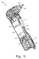
- FIG. 3shows a perspective view of the articulating drill of FIG. 1 with the battery pack, a portion of the main housing cover, and a portion of the head housing removed and a bit in the bit holder;
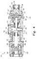
- FIG. 4shows a cross-sectional view of the head portion, the articulating gear system and the planetary gear system of the articulating drill of FIG. 1 ;
- FIG. 5shows an exploded perspective view of the head portion, including an automatic spindle lock system, of the articulating drill of FIG. 1 ;
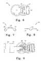
- FIG. 6shows a top plan view of the head portion of the drill of FIG. 1 with some components located within bays in the head housing;
- FIG. 7shows a top plan view of a bracket used to support an output pinion shaft in the articulating drill of FIG. 1 ;
- FIG. 8shows a side plan view of the bracket of FIG. 7 ;
- FIG. 9shows a top elevational view of the planetary gear section, articulating section and head portion of the articulating drill of FIG. 1 with the main housing and a portion of the head housing removed;
- FIG. 10shows a side elevational view of the articulating gear system of the articulating drill of FIG. 1 including a bevel gear and two pinion gears;
- FIG. 11is a perspective view of a portion of the head housing of the drill of FIG. 1 with a plurality of teeth in a well which are formed complimentary to teeth on the articulation button;
- FIG. 12shows a perspective view of the articulating button of the articulating drill of FIG. 1 ;
- FIG. 13shows a perspective view of the bottom of the articulating button of FIG. 12 ;
- FIG. 14shows a partial top elevational view of the inner surface of the outer housing of the articulating drill of FIG. 1 with teeth formed complimentary to the teeth on the articulation button and a hole for receiving a raised portion of the articulating button;
- FIG. 15shows a top elevational view of the inner surface of the outer housing of the articulating drill of FIG. 1 ;
- FIG. 16shows a partial plan view of the articulating drill of FIG. 1 with the head portion aligned with the main housing portion and without a dust lid;
- FIG. 17shows a partial plan view of the articulating drill of FIG. 1 with the head portion aligned with the main housing portion with a dust lid;
- FIG. 18shows a side elevational view of the articulating drill of FIG. 18 with the head portion rotated to an angle of 90 degrees from the main housing portion of the drill and a portion of the main housing portion removed to show the position of the dust lid of FIG. 17 ;
- FIG. 19shows a side elevational view of the articulating drill of FIG. 18 with the head portion rotated to an angle of 180 degrees from the main housing portion of the drill and a portion of the main housing portion removed to show the position of the dust lid of FIG. 17 ;
- FIG. 20shows a detail view of the dust lid of FIG. 19 ;
- FIG. 21shows a perspective view of the articulating drill of FIG. 1 with the variable speed trigger switch, clutch control and a portion of the main housing removed;
- FIGS. 22 a , 22 b and 22 cshow various views of a printed circuit board of the articulating drill of FIG. 1 in accordance with principles of the invention
- FIG. 23shows a perspective view of the articulating drill of FIG. 21 with a collapsible boot with an internal reflective surface installed over a light generator and a light sensor;
- FIG. 24shows a schematic/block diagram of the drill of FIG. 1 incorporating an optical switch for motor speed control
- FIG. 25shows a side elevational view of a drill bit in the form of a screw driver bit that may be used with the articulating drill of FIG. 1 ;
- FIG. 26shows a cross-sectional view of the drill bit of FIG. 25 being inserted into the articulating drill of FIG. 1 ;
- FIG. 27shows a cross-sectional view of the drill bit of FIG. 25 inserted into the articulating drill of FIG. 1 ;
- FIG. 28shows a partial top elevational view of a bevel gear in accordance with principles of the invention with two pinion gears at a 90 degree spacing;
- FIG. 29shows a partial top elevational view of the bevel gear of FIG. 28 with the two pinion gears at a 180 degree spacing;
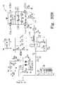
- FIG. 30shows an electrical diagram/schematic of a powered tool that dynamically brakes the tool motor using a motor interface circuit having a half bridge to provide vibratory feedback to the operator that the torque limit has been reached;
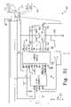
- FIG. 31shows an electrical diagram/schematic of a circuit that may be used with the drill of FIG. 1 which dynamically brakes the drill motor using a motor interface circuit having a full H-bridge circuit to provide vibratory feedback to the operator that the torque limit has been reached;
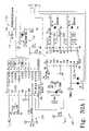
- FIGS. 32A and 32Bshow an electrical diagram/schematic of a powered tool that provides solid state motor speed control in correspondence with a variable speed signal from an optical switch and that dynamically brakes the motor to indicate a torque limit has been reached.
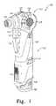
- FIG. 1An articulating drill generally designated 100 is shown in FIG. 1 .
- the drill 100includes a main housing portion 102 and a head portion 104 .
- the main housing portion 102houses a motor and associated electronics for control of the drill 100 .
- the main housing portion 102includes a battery receptacle for receiving a rechargeable battery pack 106 as is known in the art.
- the rechargeable battery pack 106comprises a lithium-ion battery.
- the battery pack 106is removed by depression of the battery release tabs 108 .
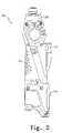
- FIG. 2shows the drill 100 with the battery pack 106 removed.
- the drill 100may alternatively be powered by an external power source such as an external battery or a power cord.
- a variable speed trigger switch 110controls the speed at which the motor rotates. The direction of rotation of the motor is controlled by a reversing button 112 which slides within a finger platform 114 . Ventilation openings 116 allow for cooling air to be circulated around the motor inside of the main housing 102 .
- a clutch control 118sets the maximum torque that may be generated when using the drill 100 . At the position shown in FIG. 1 , the clutch control 118 is at the highest setting or drill mode. At the highest setting, the clutch is disabled to provide maximum torque. By sliding the clutch control 118 downwardly from the position shown in FIG. 1 , a user may set a desired torque limit that is allowed to be generated by the drill 100 as discussed in more detail below. Accordingly, at settings other than the highest setting, a torque above the setting of the clutch control 118 causes the clutch to activate.
- the main housing portion 102also includes an articulation button 120 and a plurality of angle reference indicators 122 molded onto the outer surface 124 of the main housing 102 .
- the head portion 104includes a collet locking device 126 and an angle indicator 128 .
- the angle at which the head portion 104 is positionedis indicated by the angle reference indicator 122 with which the angle indicator 128 is aligned.
- the head portion 104is at a 90 degree angle with respect to the main housing portion 102 .
- the head portion 104is axially aligned with the main housing portion 102 .
- FIGS. 1 and 2has five angle reference indicators 122 , there may be additional or fewer angle reference indicators 122 and corresponding angles at which the head portion 104 may be placed with respect to the main housing portion 102 .
- the collet locking device 126is located around a bit holder 130 which is in turn supported by a ball bearing 132 that is fixed within a bearing pocket 134 of the head housing 136 .
- the collet locking device 126includes a sleeve 138 with recesses 140 .
- a spring 142is positioned about the bit holder 130 .
- the bit holder 130includes a hole 144 which receives a cylinder pin 146 and recesses 148 which receive steel balls 150 .
- the bearing 132abuts the head housing 136 of the head portion 104 at the outer rear periphery of the bearing 132 . More specifically, the bearing 132 abuts a flange 152 .
- the flange 152is continuous about the housing 136 , although a flange may alternatively be in the form of a plurality of fins located about the inner portion of the housing 136 .
- the bit holder 130is operably coupled to a drive collet 154 which is in turn connected to an output pinion shaft 156 through a drive plate 158 which is fixedly attached to the output pinion shaft 156 .
- a lock ring 160surrounds the drive collet 154 and three locking pins 162 .
- the lock ring 160 , the drive collet 154 , the drive plate 158 , and the locking pins 162all comprise an automatic spindle lock system such that the output bit holder 130 can only be driven from the pinion side as known in the art.
- the spindle lock systemWhen driven from the bit side, i.e., when the tool 100 is used as a manual screwdriver, the spindle lock system keeps the output pinion shaft 156 from rotating thus facilitating use of the tool 100 as a manual screwdriver.
- a manually manipulated locking devicemay be used.
- a pinion gear 164is located at the opposite end of the output pinion shaft 156 from the drive plate 158 .
- One end of the output pinion shaft 156is maintained in axial alignment by a bearing 166 which fits within bearing pocket 168 .
- the opposite end of the output pinion shaft 156is supported by a sleeve 170 .
- the sleeve 170is supported on one side by a flange 172 on the head housing 136 . On the opposite side, the sleeve 170 is supported by a bracket 174 also shown in FIGS. 7 and 8 .
- the bracket 174includes a support area 176 configured complimentary to a portion of the sleeve 170 .
- Two connection arms 178are configured to be attached to the head housing 136 as shown in FIG. 9 .
- the bracket 174eliminates the need to provide a matching flange for flange 172 molded into the opposite side of the head housing 136 .
- the elimination of the need for an opposing flangeallows for a significant increase in design freedom as the space requirements for the support structure for the sleeve 170 are reduced.
- the bracket 174may be stamped from W108 steel to provide the needed rigidity and strength.
- the pinion gear 164forms a portion of an articulating gear system 180 .
- the articulating gear system 180further includes a bevel gear 182 which is engaged at the output portion of the articulating gear system 180 with the pinion gear 164 and further engaged on the motor portion by pinion gear 184 .
- the shaft 186 of the bevel gear 182is supported at one end within a hole 188 (see FIG. 4 ) of the frame 190 .
- the frame 190is made from a zinc and aluminum alloy ZA-8. This material provides a sufficiently low coefficient of friction to ensure relatively small frictional forces exist between the shaft 186 and the frame 190 .
- the shaft 186is radially and axially supported at the opposite end by a ball bearing 192 supported by the frame 190 . At this end of the shaft 186 , however, comparatively larger forces are generated than at the end of the shaft 186 inserted within the hole 188 . More specifically, as shown in FIG. 10 , both pinion gear 164 and pinion gear 184 are located on the same side of the bevel gear 182 . Accordingly, as the articulating gear system 180 rotates, a force is generated on the bevel gear 182 in the direction of the arrow 194 toward the base 196 of the bevel gear 182 . This force acts to disengage the bevel gear 182 from the pinion gear 164 and the pinion gear 184 .
- a thrust bearing 198is provided to protect the ball bearing 192 and to provide a low friction support for the base 196 of the bevel gear 182 .
- the thrust bearing 198is made of a material with an acceptably low coefficient of friction such as oil impregnated bronze commercially available from McMaster Carr of Chicago, Ill. Accordingly, the friction generated at the base 196 of the bevel gear 182 is maintained within acceptable levels.
- the pinion gear 184is fixedly attached to a planetary gearbox shaft 200 which receives torque from a planetary gear system generally indicated as reference numeral 202 .
- the planetary gear system 202receives torque from a motor as is known in the art.
- the planetary gear system 202is located within a planetary gear housing 204 which is inserted partially within the frame 190 . This arrangement allows for the planetary gear system 202 to be separately manufactured from the other components while simplifying assembly of the planetary gear system 202 with the other components.
- This modularityfurther allows for alternative gearings to be provided in the planetary gear system 202 while ensuring a proper fit with the other components.
- the articulating gear system 180generates an axial force along the planetary gearbox shaft 200 .
- This axial forceacts to disengage the planetary gear housing 204 from the frame 190 .
- pins 206 and 208which extend through both the planetary gear housing 204 and the frame 190 are provided. The pins 206 and 208 ensure the planetary gear housing 204 does not become detached from the frame 190 during operation of the drill 100 .
- the planetary gear housing 204 and the frame 190may be formed as an integral unit.
- the frame 190is configured to slidingly mate with the head housing 136 .
- the head housing 136includes a shroud portion 210 which is complimentarily formed to the frame 190 about the ball bearing 192 .
- the head housing 136further includes a recess 212 which is configured to receive the portion of the frame 190 which defines the hole 188 .
- a well 214which includes a plurality of teeth 216 shown in FIG. 11 .
- the well teeth 216are formed complimentary to a plurality of teeth 218 which are formed in the articulation button 120 .
- the articulation button 120includes a raised center portion 220 which is configured to fit within a hole 222 in the main housing portion 102 .
- the teeth 218 of the articulation button 120are further configured to mesh with a plurality of teeth 224 formed on the inner side of the main housing portion 102 around the hole 222 .
- the articulation button 120also includes a spring receiving well 226 on the side of the articulation button 120 facing the well 214 . When assembled, a spring (not shown) is located within the well 214 and extends into the spring receiving well 226 forcing the raised center portion 220 of the articulation button 120 toward a position wherein the articulation button 120 projects into the hole 222 .
- the frame 190is supported axially in the main housing portion 102 , which in this embodiment is made of plastic, by a rib 228 .
- the rib 228lies beneath a fin 230 of the frame 190 when the frame 190 is installed in the main housing portion 102 as shown in FIG. 3 .
- the planetary gear system 202is mechanically secured to a motor 232 which is itself electrically connected to a printed circuit board 234 which in turn is electrically connected to a battery contact holder 236 .
- the contact holder 236mates with battery pack receptacles on the battery pack 106 and transmits battery power to the electronic circuit board 234 through lead wires (not shown). Another pair of lead wires (not shown) extend from the circuit board 234 to the motor terminals 238 to deliver the required voltage level to the motor 232 .
- a gap 240is provided in the portion of the head housing 136 surrounding the bevel gear 182 which allows the head housing 136 to be rotated with respect to the main housing portion 102 while the pinion gear 164 remains engaged with the bevel gear 182 .
- the gap 240is exposed as shown in FIG. 16 .
- the articulating gear system 180is thus exposed allowing contaminants access to the articulating gear system 180 which could foul the articulating gear system as well as presenting a safety concern since clothing, fingers or hair could become enmeshed in the articulating gear system 180 .
- a floating dust lid 242 shown in FIG. 17is used to prevent contamination of the articulating gear system 180 and to avoid exposure of moving gears to an operator through the gap 240 , particularly when the head housing 136 is axially aligned with the main housing portion 102 as shown in FIG. 17 .
- the dust lid 242is located in a channel 244 defined by the main housing portion 102 and the head housing 136 as shown in FIGS. 18-20 .
- the position of the dust lid 242 at the lower portion (as depicted in FIGS. 18 and 19 ) of the channel 244is constrained either by a movable dust lid travel limiter 246 positioned on the head housing 136 , shown most clearly in FIGS. 11 and 20 , or by a portion 248 of the frame 190 .
- the position of the dust lid 242 at the upper portion of the channel 244is constrained either by a neck portion 250 of the head housing 136 or by a lip 252 in the main housing portion 102 .
- the clutch control 118is mechanically interfaced with a linear potentiometer 254 on the circuit board 234 .
- a light sensor 256which is covered by a collapsible rubber boot 258 which is in turn mechanically fastened to the variable speed trigger 110 .
- a reflective surface 260(see FIG. 24 ) is located on the inside of the rubber boot 258 .
- a plastic spring locating member 262which is mechanically secured to the circuit board 234 serves to locate and support a spring 264 which is mechanically fastened to the variable speed trigger 110 . The spring 264 biases the variable speed trigger 110 in a direction away from the circuit board 234 about a pivot 266 .
- the circuit board 234also contains a two position slide switch 268 which is mechanically interfaced to the reversing button 112 .
- Manipulation of the variable speed trigger 110 about the pivot 266changes the position of the reflective surface 260 relative to the light sensor 256 to produce a variable speed control signal.
- a pressure sensing switch for generating the variable motor speed control signalmay include a pressure transducer for generating a variable speed control signal that corresponds to a pressure applied to the pressure transducer directly by the operator or through an intermediate member such as a moveable member that traverses the distance between the stop position and the full speed position.
- An embodiment of the variable motor speed control signal implemented with a capacitive proximity sensormay include a capacitive sensor that generates a variable speed control signal that corresponds to an electrical capacitance generated by the proximity of an operator's finger or moveable member's surface to the capacitive sensor.
- An embodiment implemented with an inductive proximity sensorgenerates a variable speed control signal that corresponds to an electrical inductance generated by the proximity of an operator's finger or moveable member's surface to the inductive sensor.
- variable speed control circuit 270 of the tool 100is schematically shown.
- the variable speed control circuit 270includes a power contact 272 which is operably connected to the variable speed trigger switch 110 .
- An optical signal generator 274is coupled to the battery 106 and arranged on the circuit board 232 such that light emitted from the optical signal generator 274 is directed toward the reflective surface 260 of the variable speed trigger switch 110 and directed toward the light sensor 256 .
- the light sensor 256 and the optical signal generator 274may be located in the same housing or each may be within a separate housing. When the two components are located in the same housing, the light generator and sensor may emit and receive light through a single sight glass in the housing. Alternatively, each component may have a separate sight glass.
- An integrated component having the light generator and sensor in a single housingis a QRD1114 Reflective Object Sensor available from Fairchild Semiconductor of Sunnyvale, Calif. Such a housing is substantially smaller than a potentiometer that has a wiper, which traverses approximately the same distance as the trigger traverses from the stop to the full speed position.
- the optical signal generator 274 and the light sensor 256may be an infrared light emitter and an infrared light receiver.
- an IR transceivermay be contained within a flexible dust cover that is mechanically fastened to the back of the variable speed trigger switch.
- the inside of the cover in the vicinity of the moveable triggerreflects the optical signal to the receiver for generating the speed control signal.
- Control of a tool incorporating the light sensor 256may be adversely affected by external energy sources such as the Sun.
- the collapsible boot or dust cover 258is made from an opaque material or coated with an opaque material such that energy from the sun which may leak past the housing and trigger arrangement does not affect the signal received by the light sensor 256 .
- a light sensor that is sensitive to a specific frequency bandmay be used with a device which shields the light sensor from only that specific frequency band.
- other circuitry or codingwhich uniquely identifies the energy from the reflected signal from interfering energy may be used.
- the light sensor 256is an optical transistor having a collector 276 coupled to the battery pack 106 through the contact 272 and an emitter 278 coupled to electrical ground though a voltage divider 280 and a capacitor 282 .
- a timing signal generator 284receives voltage from the voltage divider 280 .
- the timing signal generator 284is a commonly known “555” timer, although other timing signal generators may be used.
- the output of the timing signal generator 284is coupled to a gate 286 of a MOSFET 288 that has a drain 290 coupled to one of the motor terminals 238 and a source 292 coupled to electrical ground.
- the other motor terminal 238is coupled to the battery pack 106 through the contact 272 .
- a freewheeling diode 294is coupled across the motor terminals 238 .
- a bypass contact 296which is operatively connected to the variable speed trigger switch 110 , is located in parallel to the MOSFET 288 between the motor terminal 238 and electrical ground and a brake contact 298 is in parallel with the freewheeling diode 294 .
- the collet locking device 126is configured to operate with bits such as the screw driver bit 300 shown in FIG. 24 .
- the screw driver bit 300 and the bit holder 130are complimentarily shaped. In this example, both the screw driver bit 300 and the bit holder 130 are generally hexagonal in shape, although alternative shapes may be used.
- the screw driver bit 300has a diameter slightly less than the bit holder 130 so that it may fit within the bit holder 130 .
- the screw driver bit 300includes a notched area 302 and a tail portion 304 .
- the sleeve 138is moved to the right from the position shown in FIG. 4 to the position shown in FIG. 26 thereby compressing the spring 142 .
- recesses 140 in the sleeve 138are positioned adjacent to the recesses 148 in the bit holder 130 .
- the tail portion 304forces the steel balls 150 toward the recesses 140 and out of the channel of the bit holder 130 , allowing the tail portion 304 to move completely past the steel balls 150 .
- the notched area 302is aligned with the recesses 148 .
- the sleeve 138is then released, allowing the spring 142 to bias the sleeve 138 onto the bit holder 130 which is to the left from the position shown in FIG. 27 .
- the recesses 140are moved away from the recesses 148 thereby forcing the steel balls 150 partially into the channel of the bit holder 130 as shown in FIG. 27 . Movement of the steel balls 150 into the channel of the bit holder 130 is allowed since the notched area 302 is aligned with the recesses 148 .
- the bit 300is firmly held within the bit holder 130 .
- the head housing 136is then articulated to a desired angle with respect to the main housing portion 102 .
- the spring (not shown) in the spring receiving well 226forces the articulation button 120 to extend into the hole 222 .
- the teeth 218 of the articulation button 120are meshed with the teeth 224 in the main housing portion 102 as well as the teeth 216 in the well 214 of the head housing 136 , thereby angularly locking the articulation button 120 (and the head housing 136 ) with the main housing portion 102 .
- the dust lid 242is constrained at the upper portion of the channel 244 by the neck portion 250 of the head housing 136 and at the lower portion of the channel 244 by the portion 248 of the frame 190 as shown in FIG. 18 .
- FIG. 28shows the positions of the pinion gears 164 and 184 with respect to the bevel gear 182 when the drill 100 is in the configuration shown in FIG. 1 .
- the pinion gear 164is approximately 90 degrees away from the pinion gear 184 about the perimeter of the bevel gear 182 .
- the pinion gear 164articulates about the bevel gear 182 in the same direction.
- the pinion gear 164is positioned on the bevel gear 182 at a location 180 degrees away from the pinion gear 184 as shown in FIG. 29 .
- the pinion gears 164 and 184remain engaged with the bevel gear 182 . Accordingly, the bit holder 130 may be rotated by the motor 232 as the head housing 136 is articulated. Additionally, the articulation of the head housing 136 causes the movable dust lid travel limiter 246 to contact the dust lid 242 and push the dust lid 242 along the channel 244 . Thus, the dust lid 242 , which is configured to be wider than the gap 240 as shown in FIG. 17 , restricts access from outside of the drill 100 to the articulating gear system 180 .
- the operatorWhen the articulating drill 100 is rotated to the desired location, the operator reduces the force applied to the articulating button 120 .
- the spring (not shown) in the spring receiving well 226is then allowed to force the articulation button 120 away from the well 214 until the articulation button 120 extends through the hole 222 .
- the teeth 218 of the articulation button 120are meshed with the teeth 224 in the main housing portion 102 as well as the teeth 216 in the well 214 of the head housing 136 , thereby angularly locking the articulation button 120 (and the head housing 136 ) with the main housing portion 102 .
- the desired direction of rotation for the bit 300is then established by placing the reversing button 112 in the position corresponding to the desired direction of rotation in a known manner. Rotation is accomplished by moving the variable speed trigger switch 110 about the pivot 266 to close the power contact 272 . The closing of the contact 272 completes a circuit allowing current to flow to the optical signal generator 274 causing light to be emitted.
- the emitted lightstrikes the reflective surface 260 and a portion of the light is reflected toward the light sensor 256 .
- the amount of light reflected by the reflective surface 260increases as the reflective surface 260 is moved closer to the light sensor 256 .
- the increased light sensed by the light sensor 256causes increased current to be conducted by the light sensor 256 and the flow of current through the light sensor 256 causes current to flow from the collector 276 to the emitter 278 .
- the current conducted by the light sensor 256increases. This increase in current causes the voltage level presented by the voltage divider 280 to the timing signal generator 284 to increase.
- the increased signalis the variable speed signal and it causes the timing signal generator 284 to generate a timing signal in a known manner.
- the timing signal generator 284is a commonly known 555” timer, although other timing signal generators may be used.
- the timing signal generator 284generates a timing pulse having a logical on-state that corresponds to the level of the variable speed signal. This signal is presented to the gate 286 of the MOSFET 288 . When the signal present at the gate 286 is a logical on-state, the MOSFET 288 couples one of the motor terminals 238 to ground while the other motor terminal 238 is coupled to battery power through the main contact 272 . Thus, when the variable speed trigger switch 110 reaches a position where the light sensor 256 begins to detect reflected light and generate a variable speed signal, the timing signal generator 284 begins to generate a signal that causes the MOSFET 288 to couple one of the motor terminals 238 to ground. Once this occurs, current begins to flow through the MOSFET 288 and the motor 232 begins to rotate in the direction selected by the reversing button 112 .
- the freewheeling diode 294causes appropriate half-cycles of the current in the windings of the motor 232 to flow out of the motor 232 , through the diode 294 , and back into the motor 232 when the MOSFET 288 does not conduct in response to the timing signal being in the off-state. This action is known as freewheeling and is well known.
- variable speed trigger 110When the variable speed trigger 110 is in the full speed position, the timing signal is predominantly in the on-state and the bypass contact 296 closes. The closing of the bypass contact 296 enables the battery current to continuously flow through the motor 232 so that the motor 232 rotates at the highest speed.
- variable speed trigger switch 110When rotation is no longer desired, the operator releases the variable speed trigger switch 110 and the spring 264 causes the variable speed trigger switch 110 to rotate about the pivot 266 causing the bypass contact 296 to open. Additionally, the brake contact 298 closes thereby coupling the motor terminals 238 . The coupling of the two motor terminals 238 to one another through the brake contact 298 enables dynamic braking of the motor.
- the electronic control of the tool 100thus requires less space for the components that generate the variable speed signal than prior art control systems. Because the distance traveled by the variable speed trigger switch 110 does not have to be matched by the light signal generator 274 and the light sensor 256 , considerable space efficiency is gained. Additionally, the light signal generator 274 and the light sensor 256 do not require moving parts, so reliability is improved as well. Advantageously, the light signal generator 274 and the light sensor 256 may be mounted on the same printed circuit board 234 on which the timing signal generator 284 is mounted.
- the bit 300is subjected to axial forces.
- the axial forcesmay result from, for example, pressure applied by the operator or by an impact on the bit.
- the articulating gear system 180is protected from damage without increasing the bulk of the components within the articulating gear system 180 .
- Thisis accomplished by directing axial forces from the bit 300 to the main housing portion 102 of the drill 100 while bypassing the articulating gear system.
- an impact on the bit 300tends to move the bit 300 further into the drill 100 , or to the left as depicted in FIG. 27 .
- the steel balls used to retain the bit within the bit holderwould frequently jam necessitating replacement of the collet locking device.
- the cylinder pin 146is positioned such that the tail portion 304 of the bit 300 will contact the cylinder pin 146 before the wall of the notched area 302 contacts the steel balls 150 .
- an axial impactwill not cause the steel balls 150 to jam.
- the cylinder pin 146must be made from a material sufficient to withstand the axial impact.
- the cylinder pin 146is made of AISI 4135 steel.
- the forceis transferred from the cylinder pin 146 to the to the bit holder 130 .
- the axial forceis transmitted from the bit holder 130 to the bearing 132 which is located within the bearing pocket 134 . Accordingly, the axial force is transferred into the flange 152 (see also FIG. 5 ) of the head housing 136 .
- the head housing 136 in this embodimentis made from aluminum alloy A 380 so as to be capable of receiving the force transmitted by the bearing 132 .
- the forceis subsequently transferred to the frame 190 and into the rib 228 of the main housing portion 102 .
- the first pathpredominantly transfers axial forces when the head housing 136 is axially aligned with the main housing portion 102 .
- axial forcespass from head housing 136 to the frame 190 primarily through the recess 212 where the head housing 136 engages the frame 190 about the hole 188 (see FIG. 4 ) and at the shroud portion 210 where the head housing 136 engages the frame 190 outwardly of the base of the bevel gear 196 .
- the second pathpredominantly passes axial forces when the head housing 136 is at a ninety degree angle with respect to the main housing portion 102 .
- axial forcesare again transferred from the cylinder pin 146 to the to the bit holder 130 .
- the axial forcesthen pass primarily from the teeth 216 in the well 214 of the head housing 136 to the teeth 218 on the articulation button 120 and then to the teeth 224 in the main housing portion 102 .
- the head housing 136When the head housing 136 is neither completely aligned with the main housing portion 102 or at a ninety degree angle with respect to the main housing portion 102 , axial forces generally pass through both of the foregoing pathways. Accordingly, the effect of axial forces on the articulating gear system 180 of the drill 100 are reduced. Because the articulating gear system 180 is thus protected, the articulating gear system 180 may be constructed to be lighter than other articulating gear systems.
- a printed circuit boardwhich may be used in the drill 100 or another power tool includes a circuit that provides vibratory feedback to the operator as shown in FIG. 30 .
- the vibratory feedback circuit 308includes a microcontroller 310 , a driver circuit 312 , and motor interface circuit 314 .
- the driver circuit 312 in this embodimentis an integrated circuit that generates driving signals for a half-bridge circuit from a single pulse width modulated (PWM) signal, a torque limit indicating signal, which may be the same signal as the PWM signal, and a motor direction control signal.
- the driver circuit 312may be a half bridge driver, such as an Allegro 3946, which is available from Allegro Microsystems, Inc. of Worcester, Mass.
- the output of the driver circuit 312is connected to a motor 316 through two transistors 318 and 320 which may be MOSFETs, although other types of transistors may be used.
- the transistor 318may be connected to either terminal of the motor 316 through switches 322 and 324 while the transistor 320 may be connected to either terminal of the motor 316 through switches 326 and 328 .
- a shunt resistor 330is coupled between the transistor 320 and electrical ground.
- the high potential side of the resistor 330is coupled to the microcontroller 310 through an amplifier 332 .
- a power source 334is also provided in the vibratory feedback circuit 308 and a maximum torque reference signal is provided from a torque reference source 336 which may be a linear potentiometer such as the linear potentiometer 254 .
- the half-bridge control of the motor 316eliminates the need for a freewheeling diode because the driver circuit 312 generates motor interface circuit signals for selectively operating the motor interface circuit 314 to control the rotational speed of the motor 316 .
- a variable speed control signal 338which may be from a trigger potentiometer or the like, is provided to the microcontroller 310 for regulation of the rotation of the motor 316 by the microcontroller 310 .
- the microcontroller 310Based upon the variable speed control signal 338 , the microcontroller 310 generates a PWM signal that is provided to the driver circuit 312 .
- the driver circuit 312turns transistors 318 and 320 on and off.
- the transistor 318is the complement of the transistor 320 such that when the transistor 320 is on, the transistor 318 is off.
- the rate at which the transistor 320 is turned on and offdetermines the speed of motor 316 .
- the direction of rotation of the motor 316is determined by the position of the switches 322 , 324 , 326 and 328 under the control, for example, of a reversing switch.
- the current through the motor 316is provided through the transistor 320 and the resistor 330 to electrical ground when the transistor 320 is in the on-state. This current is related to the torque at which the motor 316 is operating. Thus, the voltage at the high potential side of the resistor 330 is related to the torque on the motor 316 .
- This motor torque signalis amplified by the amplifier 332 and provided to the microcontroller 310 .
- the microcontroller 310compares the amplified motor torque signal to the torque limit signal established by the torque reference source 336 .
- the torque limit signalwhich may alternatively be provided by a different type of torque limit signal generator, provides a reference signal to the microcontroller 310 that corresponds to a current through the motor 316 that represents a maximum torque setting for the motor 316 .
- the microcontroller 310In response to the microcontroller 310 receiving a motor torque signal that exceeds the maximum torque setting for the motor 316 , the microcontroller 310 generates a braking signal that is provided to the driver circuit 312 . In response to the braking signal, the driver circuit 312 turns transistor 320 to the off-state and leaves transistor 318 in the on-state. This enables regenerative current to dynamically brake the rotation of the motor 316 .
- the torque experienced by the motor 316decreases until the sensed torque is less than the maximum torque setting for the motor 316 .
- the microcontroller 310then returns the transistor 320 to the on-state, thereby rotating the motor 316 and increasing the torque experienced by the motor 316 .
- the motor 316alternates between rotating and dynamically braking which causes the tool to vibrate and alert the operator that the torque limit has been reached.
- An effective frequency for providing this vibratory feedbackis 30 Hz.
- the torque limit indicating signal that results in this operationcontinues as long as the trigger remains depressed.
- the microcontrollermay be programmed to generate the torque limit indicating signal for a fixed duration and then to stop to reduce the likelihood that the motor will be overpulsed.
- vibratory feedbackis provided for the drill 100 with the circuit shown in FIG. 31 .
- the vibratory feedback circuit 340includes a microprocessor 342 , an H-bridge driver circuit 344 and a motor interface circuit 346 .
- MOSFETs 348 , 350 , 352 and 354control power to the motor 232 from the rechargeable battery pack 106 under the control of the H-bridge driver circuit 344 .
- a shunt resistor 356is provided between the MOSFETs 352 and 354 and electrical ground. The signal at the high potential side of the resistor 356 corresponds to the torque being generated by the motor 232 .
- This motor torque signalis amplified by an amplifier circuit 358 , which may be implemented with an operational amplifier as shown in FIG.
- the microcontroller 342compares the motor torque signal to the torque limit signal and generates a torque limit indicating signal in response to the motor torque signal being equal to or greater than the torque limit signal.
- the torque limit indicating signalmay have a rectangular waveform.
- the microcontroller 342provides a torque limit indicating signal that is a rectangular signal having an off-state of at least 200 ⁇ seconds at a frequency of approximately 30 Hz.
- This torque limit indicating signalcauses the driver circuit 344 to generate motor interface control signals that disconnect power from the motor 232 and couple the MOSFETs 348 , 350 , 352 and 354 together so the current within the windings of the motor 232 flows back through the motor 232 to dynamically brake the motor 232 .
- the dynamic brakingcauses the motor 232 to stop.
- the microcontrollerBefore application of the next on-state pulse, the microcontroller inverts the signal to the direction control input of the H-bridge driver 344 .
- the subsequent on-state of the rectangular pulsecauses the H-bridge driver circuit 344 to operate the H-bridge to couple the motor 232 to the rechargeable battery pack 106 with a polarity that is the reverse of the one used to couple the motor 232 and the rechargeable battery pack 106 prior to braking.
- This brake/reverse/start operation of the motor at the 30 Hz frequencycauses the tool to vibrate in a manner that alerts the operator that the torque limit has been reached while preventing the bit from continuing to rotate during the clutching operation.
- the dynamic brakingmay also be used without inverting the signal.
- the rectangular waveformmay be generated for a fixed duration, for example, 10 to 20 pulses, so the motor is not over-pulsed.
- the microcontroller 342may invert the direction control signal to the H-bridge driver 344 during the off-time of the rectangular waveform so that the motor 232 starts in the opposite direction each time. This action results in the net output rotation being zero during the clutching duration. Additionally, the microcontroller 342 may disable the clutching function in response to the motor direction control signal indicating reverse, rather than forward, operation of the motor 232 .
- FIGS. 32A and 32Bdepict an embodiment of a circuit used in a tool that eliminates the need for mechanical contacts.
- the circuit 360includes an optical speed control switch 362 , a two position forward/reverse switch 364 , a microcontroller 366 , a driver circuit 368 , an H-bridge circuit 370 , a motor 372 , a shunt resistor 374 , a motor torque signal amplifier 376 , and a torque limit signal generator 378 .
- poweris coupled to the motor 372 through the H-bridge circuit 370 , but the main contact, brake contact, and bypass contact are no longer required.
- this embodimentsignificantly reduces the number of components that are subject to mechanical wear and degradation.
- optical control switch 362microcontroller 366 , driver circuit 368 , H-bridge circuit 370 , and torque signal amplifier 376 may all be implemented with integrated circuits, then ICs may be mounted on a common printed circuit and the space previously occupied by the mechanical contacts and variable signal potentiometer are gained. This construction further enables the tool components to be arranged in more efficient geometries.
- the optical speed control switch 362operates as described above to generate a variable control signal from the reflection of an optical signal directed at the reflective surface of a pivoting trigger.
- the variable speed control signalis provided to the microcontroller 366 for processing.
- the microcontroller 366which may be a microcontroller available from Texas Instruments and designated by part number MSP430, is programmed with instructions to generate a PWM pulse with an on-state that corresponds to the level of the variable speed signal.
- the microcontroller 366provides the PWM signal to the driver circuit 368 for generation of the four motor interface control signals used to couple battery power to the motor 372 .
- the direction in which the motor 372 is drivenis determined by the contacts in the two position forward/reverse switch 364 through which a signal is provided to the microcontroller 366 .
- the contacts of the two position forward/reverse switch 364do not need to carry the current provided to the motor 372 so the contacts of the two position forward/reverse switch 364 may be smaller than contacts in other systems.
- the directional signalis also provided by the microcontroller 366 to the driver circuit 368 so the driver circuit 368 is capable of two directional control of current in the H-bridge circuit 370 .
- the motor torque signal amplifier 376provides the torque signal from the high potential side of the shunt resistor 374 to the microcontroller 366 .
- the torque limit signal generator 378may be implemented with a potentiometer as described above to provide a reference signal for the microcontroller 366 .
- the microcontroller 366determines that the motor torque signal equals or exceeds the motor torque limit, the microcontroller 366 generates a torque limit indicating signal so the driver circuit 368 generates the motor interface control signals that operate the motor 372 in a manner that causes vibration.
- the torque limit indicating signal generated by the microcontroller 366is a rectangular signal having an off-state of at least about 200 ⁇ seconds at a frequency of about 30 Hz.
Landscapes
- Engineering & Computer Science (AREA)
- Mechanical Engineering (AREA)
- Power Engineering (AREA)
- Percussive Tools And Related Accessories (AREA)
- Drilling And Boring (AREA)
- Surgical Instruments (AREA)
- Control Of Direct Current Motors (AREA)
- Prostheses (AREA)
- Automatic Control Of Machine Tools (AREA)
- Control Of Electric Motors In General (AREA)
- Portable Power Tools In General (AREA)
- Toys (AREA)
Abstract
Description
Claims (11)
Priority Applications (1)
| Application Number | Priority Date | Filing Date | Title |
|---|---|---|---|
| US11/592,829US7708085B2 (en) | 2005-11-04 | 2006-11-03 | Articulating drill with optical speed control and method of operation |
Applications Claiming Priority (2)
| Application Number | Priority Date | Filing Date | Title |
|---|---|---|---|
| US73354605P | 2005-11-04 | 2005-11-04 | |
| US11/592,829US7708085B2 (en) | 2005-11-04 | 2006-11-03 | Articulating drill with optical speed control and method of operation |
Publications (2)
| Publication Number | Publication Date |
|---|---|
| US20070144872A1 US20070144872A1 (en) | 2007-06-28 |
| US7708085B2true US7708085B2 (en) | 2010-05-04 |
Family
ID=37794169
Family Applications (8)
| Application Number | Title | Priority Date | Filing Date |
|---|---|---|---|
| US11/592,580Active2027-01-16US7400106B2 (en) | 2005-11-04 | 2006-11-03 | Method and apparatus for providing torque limit feedback in a power drill |
| US11/592,567Expired - Fee RelatedUS7487844B2 (en) | 2005-11-04 | 2006-11-03 | Drill with solid state speed control |
| US11/593,187Active2027-04-20US7926585B2 (en) | 2005-11-04 | 2006-11-03 | Method and apparatus for an articulating drill |
| US11/592,829Expired - Fee RelatedUS7708085B2 (en) | 2005-11-04 | 2006-11-03 | Articulating drill with optical speed control and method of operation |
| US11/592,603Expired - Fee RelatedUS8322456B2 (en) | 2005-11-04 | 2006-11-03 | Articulating drill with integrated circuit board and method of operation |
| US12/367,698Expired - Fee RelatedUS7861796B2 (en) | 2005-11-04 | 2009-02-09 | Method of operating drill with solid state speed control |
| US13/669,809Expired - Fee RelatedUS8561717B2 (en) | 2005-11-04 | 2012-11-06 | Articulating drill with integrated circuit board and method of operation |
| US14/060,404Expired - Fee RelatedUS8985241B2 (en) | 2005-11-04 | 2013-10-22 | Articulating drill with integrated circuit board and method of operation |
Family Applications Before (3)
| Application Number | Title | Priority Date | Filing Date |
|---|---|---|---|
| US11/592,580Active2027-01-16US7400106B2 (en) | 2005-11-04 | 2006-11-03 | Method and apparatus for providing torque limit feedback in a power drill |
| US11/592,567Expired - Fee RelatedUS7487844B2 (en) | 2005-11-04 | 2006-11-03 | Drill with solid state speed control |
| US11/593,187Active2027-04-20US7926585B2 (en) | 2005-11-04 | 2006-11-03 | Method and apparatus for an articulating drill |
Family Applications After (4)
| Application Number | Title | Priority Date | Filing Date |
|---|---|---|---|
| US11/592,603Expired - Fee RelatedUS8322456B2 (en) | 2005-11-04 | 2006-11-03 | Articulating drill with integrated circuit board and method of operation |
| US12/367,698Expired - Fee RelatedUS7861796B2 (en) | 2005-11-04 | 2009-02-09 | Method of operating drill with solid state speed control |
| US13/669,809Expired - Fee RelatedUS8561717B2 (en) | 2005-11-04 | 2012-11-06 | Articulating drill with integrated circuit board and method of operation |
| US14/060,404Expired - Fee RelatedUS8985241B2 (en) | 2005-11-04 | 2013-10-22 | Articulating drill with integrated circuit board and method of operation |
Country Status (5)
| Country | Link |
|---|---|
| US (8) | US7400106B2 (en) |
| EP (5) | EP1943060B1 (en) |
| CN (5) | CN101300732B (en) |
| DE (2) | DE602006020757D1 (en) |
| WO (5) | WO2007056255A2 (en) |
Cited By (25)
| Publication number | Priority date | Publication date | Assignee | Title |
|---|---|---|---|---|
| USD623496S1 (en)* | 2009-07-10 | 2010-09-14 | Hitachi Koki Co., Ltd. | Portable electric grinder |
| US20100326804A1 (en)* | 2009-06-30 | 2010-12-30 | Dietmar Saur | Hand-held power tool |
| US20110186318A1 (en)* | 2010-02-02 | 2011-08-04 | Makita Corporation | Motor control device, electric power tool, and recording medium |
| US20110303432A1 (en)* | 2010-06-14 | 2011-12-15 | Stauffer Joseph G | Power tool transmission |
| US8286723B2 (en) | 2010-01-07 | 2012-10-16 | Black & Decker Inc. | Power screwdriver having rotary input control |
| WO2012068016A3 (en)* | 2010-11-16 | 2012-11-22 | Milwaukee Electric Tool Corporation | Impact tool |
| US20130056235A1 (en)* | 2005-11-04 | 2013-03-07 | Robert Bosch Gmbh | Articulating Drill with Integrated Circuit Board and Method of Operation |
| US8418778B2 (en) | 2010-01-07 | 2013-04-16 | Black & Decker Inc. | Power screwdriver having rotary input control |
| USRE44311E1 (en) | 2004-10-20 | 2013-06-25 | Black & Decker Inc. | Power tool anti-kickback system with rotational rate sensor |
| US8493172B2 (en) | 2011-09-30 | 2013-07-23 | Snap-On Incorporated | Variable speed toggle trigger |
| USD703017S1 (en) | 2011-01-07 | 2014-04-22 | Black & Decker Inc. | Screwdriver |
| US8919456B2 (en) | 2012-06-08 | 2014-12-30 | Black & Decker Inc. | Fastener setting algorithm for drill driver |
| US9216504B2 (en) | 2010-03-23 | 2015-12-22 | Black & Decker Inc. | Spindle bearing arrangement for a power tool |
| US9266178B2 (en) | 2010-01-07 | 2016-02-23 | Black & Decker Inc. | Power tool having rotary input control |
| US9308630B2 (en)* | 2013-12-20 | 2016-04-12 | Chervon Intellectual Property Limited | Impact screwdriver |
| US9475180B2 (en) | 2010-01-07 | 2016-10-25 | Black & Decker Inc. | Power tool having rotary input control |
| US9559628B2 (en) | 2013-10-25 | 2017-01-31 | Black & Decker Inc. | Handheld power tool with compact AC switch |
| US9908182B2 (en) | 2012-01-30 | 2018-03-06 | Black & Decker Inc. | Remote programming of a power tool |
| US9956676B2 (en) | 2013-01-09 | 2018-05-01 | Techtronic Power Tools Technology Limited | Tool with rotatable head |
| US10589413B2 (en) | 2016-06-20 | 2020-03-17 | Black & Decker Inc. | Power tool with anti-kickback control system |
| US11097405B2 (en) | 2017-07-31 | 2021-08-24 | Ingersoll-Rand Industrial U.S., Inc. | Impact tool angular velocity measurement system |
| US11201572B2 (en) | 2019-06-10 | 2021-12-14 | Milwaukee Electric Tool Corporation | Motor braking using selectively connectable resistance |
| US12044530B2 (en) | 2008-07-10 | 2024-07-23 | Black & Decker Inc. | Communication protocol for remotely controlled laser devices |
| US12226884B2 (en) | 2021-11-29 | 2025-02-18 | Ingersoll-Rand Industrial U.S., Inc. | High resolution anvil angle sensor |
| US12318906B2 (en) | 2012-06-08 | 2025-06-03 | Black & Decker Inc. | Power tool having multiple operating modes |
Families Citing this family (183)
| Publication number | Priority date | Publication date | Assignee | Title |
|---|---|---|---|---|
| DE102004051913A1 (en)* | 2004-08-09 | 2006-02-23 | Robert Bosch Gmbh | Cordless Screwdriver |
| GB2426390B (en) | 2005-05-17 | 2009-02-18 | Milwaukee Electric Tool Corp | Power tool, battery, charger and method of operating the same |
| DE102006023187B4 (en) | 2005-05-17 | 2020-02-27 | Milwaukee Electric Tool Corp. | Method for operating a battery charger and a combination comprising a battery and a battery charger |
| US7980159B1 (en) | 2005-11-30 | 2011-07-19 | Western Digital Technologies, Inc. | Methods, devices and systems for screw feeding by vacuum and gravity |
| US7743683B2 (en)* | 2006-08-15 | 2010-06-29 | Umagination Labs, L.P. | Systems and methods of a power tool system with interchangeable functional attachments powered by a direct rotational drive |
| US7802633B2 (en)* | 2006-09-18 | 2010-09-28 | Sp Air Kabushiki Kaisha | Reversible valve assembly for a pneumatic tool |
| US7779931B2 (en)* | 2006-11-10 | 2010-08-24 | Joel Townsan | Electric hand screwdriver with adjustable head |
| DE102006059633B4 (en)* | 2006-12-14 | 2016-12-01 | Robert Bosch Gmbh | impact drill |
| DE102006061625A1 (en)* | 2006-12-27 | 2008-07-03 | Robert Bosch Gmbh | Electric hand tool e.g. drill hammer, has motor connectable with spindle and/or sliding tool over transmission and pivotable around axis, where middle axle of shaft of transmission or central axle of drive shaft forms axis |
| JP5242974B2 (en)* | 2007-08-24 | 2013-07-24 | 株式会社マキタ | Electric tool |
| DE102008052852A1 (en)* | 2007-10-27 | 2009-04-30 | Marquardt Gmbh | Circuit arrangement for a power tool |
| US8407902B2 (en) | 2008-03-07 | 2013-04-02 | Milwaukee Electric Tool Corporation | Reciprocating power tool having a counterbalance device |
| GB2489865B (en)* | 2008-03-07 | 2012-12-19 | Milwaukee Electric Tool Corp | Portable battery-powered reciprocating saw |
| US7823486B2 (en)* | 2008-05-09 | 2010-11-02 | Wise Robert W | Cordless motor assisted torque wrench |
| US20090309527A1 (en)* | 2008-06-16 | 2009-12-17 | General Electric Company | Method and system for dynamic motor braking |
| JP5463014B2 (en)* | 2008-07-04 | 2014-04-09 | 株式会社マキタ | Electric tool |
| USD602756S1 (en)* | 2008-11-26 | 2009-10-27 | C. & E. Fein Gmbh | Oscillating tool |
| JP4961418B2 (en)* | 2008-12-26 | 2012-06-27 | オムロン株式会社 | Electric tool |
| JP5203243B2 (en)* | 2009-02-03 | 2013-06-05 | 株式会社マキタ | Screw tightening tool |
| JP5537055B2 (en)* | 2009-03-24 | 2014-07-02 | 株式会社マキタ | Electric tool |
| US8011444B2 (en)* | 2009-04-03 | 2011-09-06 | Ingersoll Rand Company | Spindle locking assembly |
| CN101876812B (en)* | 2009-04-28 | 2012-07-04 | 南京德朔实业有限公司 | Control method of electric shears |
| US8230570B1 (en) | 2009-06-12 | 2012-07-31 | Western Digital Technologies, Inc. | Automatic gravity vacuum screw feeding |
| DE102009027111A1 (en)* | 2009-06-23 | 2010-12-30 | Robert Bosch Gmbh | Electric machine tool |
| DE102009027705A1 (en)* | 2009-07-15 | 2011-01-20 | Robert Bosch Gmbh | Hand-held power tool |
| CN101961795A (en)* | 2009-07-23 | 2011-02-02 | 德昌电机(深圳)有限公司 | Electric tool |
| US9071188B2 (en)* | 2009-09-04 | 2015-06-30 | Black & Decker Inc. | Protective redundant subsystem for power tools |
| CN201565933U (en)* | 2009-10-30 | 2010-09-01 | 南京德朔实业有限公司 | Electric hammer |
| JP5394895B2 (en)* | 2009-11-11 | 2014-01-22 | 株式会社マキタ | Electric tool |
| JP5463907B2 (en)* | 2009-12-28 | 2014-04-09 | 日立工機株式会社 | Electric tool |
| JP5351752B2 (en)* | 2009-12-28 | 2013-11-27 | 株式会社マキタ | Electric tool |
| US9266230B2 (en)* | 2010-01-07 | 2016-02-23 | Black & Decker Inc. | Twist-handled power tool with locking system |
| US8555999B2 (en)* | 2010-04-30 | 2013-10-15 | Black & Decker Inc. | Twist-handled power tool with locking system |
| US20130227809A1 (en) | 2012-02-24 | 2013-09-05 | Pylon Manufacturing Corp. | Wiper blade |
| US20130020102A1 (en)* | 2010-02-17 | 2013-01-24 | Gardena Manufacturing Gmbh | Power Tools |
| JP5510807B2 (en)* | 2010-03-08 | 2014-06-04 | 日立工機株式会社 | Impact tools |
| JP5463987B2 (en)* | 2010-03-17 | 2014-04-09 | 日立工機株式会社 | Electric tool |
| US9722334B2 (en) | 2010-04-07 | 2017-08-01 | Black & Decker Inc. | Power tool with light unit |
| CN101837578A (en)* | 2010-05-11 | 2010-09-22 | 南京德朔实业有限公司 | Portable angular tool |
| DE102010029267A1 (en)* | 2010-05-25 | 2011-12-01 | Robert Bosch Gmbh | Power tool, in particular drill driver |
| EP3756834B1 (en)* | 2010-07-02 | 2021-12-08 | Husqvarna Ab | Battery powered tool |
| CN102371573A (en)* | 2010-08-10 | 2012-03-14 | 南京德朔实业有限公司 | Electric tool |
| USD649421S1 (en)* | 2010-09-09 | 2011-11-29 | Robert Bosch Gmbh | Power tool |
| US9120160B1 (en)* | 2010-10-20 | 2015-09-01 | Ahmed Eldessouky | Positive feed drill |
| DE102010063069A1 (en)* | 2010-12-14 | 2012-06-14 | Robert Bosch Gmbh | Hand tool, in particular drill or Schraubbohrmaschine |
| US9038745B2 (en) | 2010-12-20 | 2015-05-26 | Brigham Young University | Hand power tool and drive train |
| USD670148S1 (en)* | 2011-04-14 | 2012-11-06 | Ching-Yi Wang | Multiple-angle transmission tool |
| US9457768B2 (en) | 2011-04-21 | 2016-10-04 | Pylon Manufacturing Corp. | Vortex damping wiper blade |
| EP2524773B1 (en) | 2011-05-19 | 2017-06-21 | Black & Decker Inc. | Electronic power apparatus for a power tool |
| US8789446B1 (en) | 2011-06-28 | 2014-07-29 | Western Digital Technologies, Inc. | Screw feeding apparatus to deliver a screw from a vibrating rail to a screw guide tube |
| MX345011B (en) | 2011-07-28 | 2017-01-11 | Pylon Mfg Corp | Windshield wiper adapter, connector and assembly. |
| US9108595B2 (en) | 2011-07-29 | 2015-08-18 | Pylon Manufacturing Corporation | Windshield wiper connector |
| DE102011109133B4 (en)* | 2011-08-02 | 2020-10-22 | Robert Bosch Gmbh | Transportable screwdriving tool with integrated switching element |
| US20130133210A1 (en) | 2011-11-30 | 2013-05-30 | Robert Bosch Gmbh | Articulating Jig Saw |
| EP2799188A4 (en)* | 2011-12-28 | 2015-08-12 | Positec Power Tools Suzhou Co | Power tool |
| US8881409B2 (en) | 2012-01-16 | 2014-11-11 | Robert Bosch Gmbh | Articulating oscillating power tool |
| US20130200823A1 (en)* | 2012-02-02 | 2013-08-08 | Conair Corporation | Motor for hair grooming apparatus |
| TW201332725A (en)* | 2012-02-10 | 2013-08-16 | Master Air Tool Co Ltd | Pneumatic tool head structure |
| US10723322B2 (en) | 2012-02-24 | 2020-07-28 | Pylon Manufacturing Corp. | Wiper blade with cover |
| US20130219649A1 (en) | 2012-02-24 | 2013-08-29 | Pylon Manufacturing Corp. | Wiper blade |
| US9193055B2 (en) | 2012-04-13 | 2015-11-24 | Black & Decker Inc. | Electronic clutch for power tool |
| US9259790B2 (en)* | 2012-04-23 | 2016-02-16 | Black & Decker Inc. | Power tool with automatic chuck |
| DE102012206884A1 (en)* | 2012-04-26 | 2013-10-31 | Robert Bosch Gmbh | Hand tool |
| US9450471B2 (en) | 2012-05-24 | 2016-09-20 | Milwaukee Electric Tool Corporation | Brushless DC motor power tool with combined PCB design |
| DE202013103023U1 (en)* | 2012-07-14 | 2013-10-04 | Hitachi Koki Co., Ltd. | power tool |
| GB201212958D0 (en)* | 2012-07-20 | 2012-09-05 | Hosking Peter J | Power tools |
| US10829092B2 (en) | 2012-09-24 | 2020-11-10 | Pylon Manufacturing Corp. | Wiper blade with modular mounting base |
| DE102012221748A1 (en)* | 2012-11-28 | 2014-05-28 | Robert Bosch Gmbh | Hand tool |
| EP3189940B1 (en)* | 2012-12-25 | 2018-01-31 | Makita Corporation | Impact tool |
| US9550283B2 (en) | 2013-01-24 | 2017-01-24 | Ingersoll-Rand Company | Power tool with spindle lock |
| US20150328764A1 (en) | 2013-02-01 | 2015-11-19 | Makita Corporation | Power tool |
| JP2014148006A (en)* | 2013-02-01 | 2014-08-21 | Makita Corp | Electric power tool and portable circular saw |
| EP2961572B1 (en) | 2013-02-26 | 2016-09-21 | Apex Brands, Inc. | Low pressure shut off for a pneumatic tool |
| US10668613B2 (en) | 2013-03-14 | 2020-06-02 | Robert Bosch Tool Corporation | Slide switch for a power tool |
| US10166951B2 (en) | 2013-03-15 | 2019-01-01 | Pylon Manufacturing Corp. | Windshield wiper connector |
| US9150360B1 (en) | 2013-05-16 | 2015-10-06 | Western Digital Technologies, Inc. | Mechanism to deliver fastener vertically |
| US9787159B2 (en) | 2013-06-06 | 2017-10-10 | Milwaukee Electric Tool Corporation | Brushless DC motor configuration for a power tool |
| WO2014201174A1 (en)* | 2013-06-11 | 2014-12-18 | Spin Chill Corp. | Container spinning device and method of use thereof |
| US9889066B2 (en) | 2013-07-01 | 2018-02-13 | Good Fortune 5, Llc | Massaging device having a heat sink |
| US9265551B2 (en) | 2013-07-19 | 2016-02-23 | Pro-Dex, Inc. | Torque-limiting screwdrivers |
| GB2519962A (en)* | 2013-11-01 | 2015-05-13 | Robert Fowler | A handheld power tool |
| DE102013223819A1 (en)* | 2013-11-21 | 2015-05-21 | Robert Bosch Gmbh | Hand tool housing device |
| DE102013224759A1 (en)* | 2013-12-03 | 2015-06-03 | Robert Bosch Gmbh | Machine tool device |
| US10014128B2 (en)* | 2013-12-17 | 2018-07-03 | Robert Bosch Tool Corporation | Portable power tool with trigger switch, trigger release and lock-on mechanism combination |
| US9505380B2 (en) | 2014-03-07 | 2016-11-29 | Pylon Manufacturing Corp. | Windshield wiper connector and assembly |
| US9561568B2 (en)* | 2014-04-25 | 2017-02-07 | Black & Decker Inc. | Magnetic drill press with alternate power source |
| US20160039012A1 (en)* | 2014-08-11 | 2016-02-11 | Hsiu-Lin HSU | Magnetic Coupling Spindle For Automatic Screwdrivers |
| CN107251264B (en) | 2014-11-26 | 2020-10-13 | 创科实业有限公司 | Battery |
| JP6357086B2 (en)* | 2014-11-26 | 2018-07-11 | 株式会社マキタ | Electric equipment |
| EP3251801A4 (en)* | 2015-01-28 | 2018-09-19 | Koki Holdings Kabushiki Kaisha | Impact tool |
| US10406662B2 (en)* | 2015-02-27 | 2019-09-10 | Black & Decker Inc. | Impact tool with control mode |
| US10697250B2 (en)* | 2015-04-02 | 2020-06-30 | Sandvik Intellectual Property Ab | Multi-functional connector, drill head, and method |
| US10637379B2 (en)* | 2015-04-07 | 2020-04-28 | Black & Decker Inc. | Power tool with automatic feathering mode |
| KR102074052B1 (en)* | 2015-06-02 | 2020-02-05 | 밀워키 일렉트릭 툴 코포레이션 | Multi-speed power tools with electronic clutch |
| CN107635726A (en)* | 2015-06-05 | 2018-01-26 | 英古所连公司 | Power tool with user's selectively actuatable pattern |
| WO2016196918A1 (en) | 2015-06-05 | 2016-12-08 | Ingersoll-Rand Company | Power tool user interfaces |
| WO2016196979A1 (en) | 2015-06-05 | 2016-12-08 | Ingersoll-Rand Company | Impact tools with ring gear alignment features |
| US11260517B2 (en) | 2015-06-05 | 2022-03-01 | Ingersoll-Rand Industrial U.S., Inc. | Power tool housings |
| WO2016196984A1 (en) | 2015-06-05 | 2016-12-08 | Ingersoll-Rand Company | Power tools with user-selectable operational modes |
| US11957635B2 (en) | 2015-06-20 | 2024-04-16 | Therabody, Inc. | Percussive therapy device with variable amplitude |
| US10357425B2 (en) | 2015-06-20 | 2019-07-23 | Theragun, LLC | Massage device and method of use |
| US10857064B2 (en) | 2018-12-26 | 2020-12-08 | Theragun, Inc. | Percussive therapy device |
| US10702448B2 (en) | 2017-03-14 | 2020-07-07 | Theragun, Inc. | Percussive massage device and method of use |
| US11160721B2 (en) | 2015-06-20 | 2021-11-02 | Theragun, Inc. | Percussive therapy device with variable amplitude |
| US9659468B2 (en)* | 2015-09-16 | 2017-05-23 | Immersion Corporation | Haptic feedback in a haptically noisy environment |
| JP6513006B2 (en)* | 2015-09-30 | 2019-05-15 | 株式会社マキタ | Motor control device |
| WO2017075066A1 (en) | 2015-10-26 | 2017-05-04 | Pylon Manufacturing Corp. | Wiper blade |
| KR101782535B1 (en)* | 2016-01-28 | 2017-10-24 | 대모 엔지니어링 주식회사 | Hydraulic breaker |
| JP6758853B2 (en)* | 2016-02-22 | 2020-09-23 | 株式会社マキタ | Angle tool |
| JP6555167B2 (en)* | 2016-03-25 | 2019-08-07 | 株式会社安川電機 | Electric motor and brake release method |
| WO2017201485A1 (en) | 2016-05-19 | 2017-11-23 | Pylon Manufacturing Corp. | Windshield wiper connector |
| WO2017201470A1 (en) | 2016-05-19 | 2017-11-23 | Pylon Manufacturing Corp. | Windshield wiper connector |
| WO2017201458A1 (en) | 2016-05-19 | 2017-11-23 | Pylon Manufacturing Corp. | Windshield wiper connector |
| EP3458315B1 (en) | 2016-05-19 | 2021-09-08 | Pylon Manufacturing Corp. | Windshield wiper blade |
| US11040705B2 (en) | 2016-05-19 | 2021-06-22 | Pylon Manufacturing Corp. | Windshield wiper connector |
| WO2017214194A1 (en) | 2016-06-07 | 2017-12-14 | Pro-Dex, Inc. | Torque-limiting screwdriver devices, systems, and methods |
| JP6758960B2 (en)* | 2016-07-05 | 2020-09-23 | 株式会社マキタ | Rechargeable power tool |
| CN106122233B (en)* | 2016-07-20 | 2018-10-12 | 上海宇航系统工程研究所 | The not de- clamp device of pine and its electric wrench |
| US10220493B2 (en) | 2016-09-06 | 2019-03-05 | Ingersoll-Rand Company | Spindle lock mechanism for pneumatic right-angle impact tool |
| US10625405B2 (en) | 2016-09-13 | 2020-04-21 | Milwaukee Electric Tool Corporation | Powered ratcheting torque wrench |
| US11453105B2 (en) | 2016-09-13 | 2022-09-27 | Milwaukee Electric Tool Corporation | Powered ratcheting torque wrench |
| DE102016117783B4 (en)* | 2016-09-21 | 2023-11-16 | Johnson Electric Germany GmbH & Co. KG | Electric switch |
| US10427270B2 (en) | 2016-10-01 | 2019-10-01 | Ingersoll-Rand Company | Belt sander ergonomic articulating arm belt with button release, lock, and sealed housing |
| US10875168B2 (en) | 2016-10-07 | 2020-12-29 | Makita Corporation | Power tool |
| JP6863704B2 (en) | 2016-10-07 | 2021-04-21 | 株式会社マキタ | Strike tool |
| CN106426010B (en)* | 2016-10-12 | 2018-12-18 | 戴震班 | A kind of turning device |
| WO2018088443A1 (en)* | 2016-11-10 | 2018-05-17 | 日東工器株式会社 | Electric tool, and control device and control circuit for same |
| CN106863619A (en)* | 2017-02-17 | 2017-06-20 | 苏州益普敦新材料科技有限公司 | A kind of mixing of construction material with opening cycle of higher pressure boring device soon |
| US10608501B2 (en) | 2017-05-24 | 2020-03-31 | Black & Decker Inc. | Variable-speed input unit having segmented pads for a power tool |
| JP6920441B2 (en) | 2017-08-03 | 2021-08-18 | 株式会社マキタ | Electric wrench |
| JP7039209B2 (en)* | 2017-08-09 | 2022-03-22 | 株式会社マキタ | Polisher |
| JP6953252B2 (en)* | 2017-09-19 | 2021-10-27 | 株式会社マキタ | Rotating tool |
| EP3476543A1 (en)* | 2017-10-26 | 2019-05-01 | Max Co., Ltd. | Tool and electric tool |
| US11447108B1 (en)* | 2017-10-30 | 2022-09-20 | Creed Monarch, Inc. | Braking control system and method to sysnchronize the operation of the braking of a towed vehicle |
| CN109755975B (en)* | 2017-11-02 | 2021-12-07 | 苏州宝时得电动工具有限公司 | Electric tool control method and circuit |
| US10889474B2 (en)* | 2017-12-08 | 2021-01-12 | Hall Labs Llc | Battery cell shifting in rotational motor applications |
| CN109199525B (en)* | 2017-12-20 | 2024-08-20 | 上海博进医疗器械有限公司 | Multifunctional medical bone drill |
| CN108188967B (en)* | 2018-03-28 | 2019-11-15 | 蔡会多 | An electric screwdriver with automatic correction function |
| US12010799B2 (en)* | 2018-06-28 | 2024-06-11 | Black & Decker Inc. | Electronic switch module with oppositely-arranged power switches and discrete heat sinks |
| TWI660806B (en)* | 2018-07-09 | 2019-06-01 | 愛烙達股份有限公司 | Hand-held tool |
| CN112566754B (en) | 2018-08-20 | 2023-04-18 | 普罗德克斯有限公司 | Torque limiting device, system and method |
| JP7326997B2 (en)* | 2018-09-07 | 2023-08-16 | マックス株式会社 | binding machine |
| ES2987261T3 (en)* | 2018-09-07 | 2024-11-14 | Max Co Ltd | Binder |
| US11890253B2 (en) | 2018-12-26 | 2024-02-06 | Therabody, Inc. | Percussive therapy device with interchangeable modules |
| US10959911B2 (en) | 2018-12-26 | 2021-03-30 | Theragun, Inc. | Percussive therapy device with active control |
| US11357697B2 (en) | 2018-12-26 | 2022-06-14 | Therabody, Inc. | Percussive therapy device |
| US12064387B2 (en) | 2018-12-26 | 2024-08-20 | Therabody, Inc. | Percussive therapy device with electrically connected attachment |
| US10940081B2 (en) | 2019-05-07 | 2021-03-09 | Theragun, Inc. | Percussive massage device with force meter |
| US11564860B2 (en) | 2018-12-26 | 2023-01-31 | Therabody, Inc. | Percussive therapy device with electrically connected attachment |
| US11432994B2 (en) | 2018-12-26 | 2022-09-06 | Therabody, Inc. | Intelligence engine system and method |
| US11452670B2 (en) | 2018-12-26 | 2022-09-27 | Therabody, Inc. | Percussive therapy device with orientation, position, and force sensing and accessory therefor |
| US11897094B2 (en)* | 2019-01-07 | 2024-02-13 | Milwaukee Electric Tool Corporation | Powered ratcheting wrench |
| JP7246202B2 (en) | 2019-02-19 | 2023-03-27 | 株式会社マキタ | Power tool with vibration mechanism |
| JP7229807B2 (en) | 2019-02-21 | 2023-02-28 | 株式会社マキタ | Electric tool |
| US11945087B2 (en) | 2019-03-29 | 2024-04-02 | Tien-I Industrial Co., Ltd. | Impact tool head |
| US11813221B2 (en) | 2019-05-07 | 2023-11-14 | Therabody, Inc. | Portable percussive massage device |
| US11998504B2 (en) | 2019-05-07 | 2024-06-04 | Therabody, Inc. | Chair including percussive massage therapy |
| DE102019213720A1 (en)* | 2019-09-10 | 2021-03-11 | Robert Bosch Gmbh | Hand machine tool and method for operating the hand machine tool |
| EP3792009B1 (en)* | 2019-09-12 | 2024-04-24 | Andreas Stihl AG & Co. KG | Hand-guided appliance with a tool |
| DE102019215415A1 (en)* | 2019-10-09 | 2021-04-15 | Robert Bosch Gmbh | Method for teaching in application shutdowns with the help of finding characteristic signal forms when operating a handheld power tool |
| JP7178591B2 (en)* | 2019-11-15 | 2022-11-28 | パナソニックIpマネジメント株式会社 | Impact tool, impact tool control method and program |
| CN110880855B (en)* | 2019-11-28 | 2020-09-18 | 山东三木环保工程有限公司 | Working method of linear motor driven tamping tool |
| CN111168118B (en)* | 2020-01-10 | 2021-06-01 | 江苏海泰锻压设备有限公司 | Disk part drilling machine of side seam processing |
| US11806095B2 (en) | 2020-06-17 | 2023-11-07 | Mazor Robotics Ltd. | Torque sensor with decision support and related systems and methods |
| DE102020212936A1 (en) | 2020-10-14 | 2022-04-14 | Robert Bosch Gesellschaft mit beschränkter Haftung | Electronic H-bridge control |
| TWI750884B (en)* | 2020-11-04 | 2021-12-21 | 朝程工業股份有限公司 | electrical tools |
| CN114643566A (en)* | 2020-12-18 | 2022-06-21 | 南京泉峰科技有限公司 | Electric tool |
| US20220286132A1 (en)* | 2021-03-04 | 2022-09-08 | Snap-On Incorporated | Non-contact direction selector mechanism |
| US12343302B2 (en) | 2021-08-13 | 2025-07-01 | Hyperice Ip Subco, Llc | Combination applicator and adapter for percussive massage device |
| JP2023027867A (en)* | 2021-08-18 | 2023-03-03 | 瓜生製作株式会社 | Electric power tool comprising trigger switch using light sensor |
| CN114274063A (en)* | 2021-11-25 | 2022-04-05 | 中之捷(常州)汽车零部件再制造有限公司 | Handheld electric disassembling clamp |
| SE545773C2 (en)* | 2021-12-10 | 2024-01-09 | Atlas Copco Ind Technique Ab | Method of controlling an electric motor of a tightening tool |
| US11857481B2 (en) | 2022-02-28 | 2024-01-02 | Therabody, Inc. | System for electrical connection of massage attachment to percussive therapy device |
| DE202023002791U1 (en)* | 2022-04-07 | 2024-07-10 | Milwaukee Electric Tool Corporation | Powered ratchet tool |
| WO2024044546A1 (en)* | 2022-08-22 | 2024-02-29 | Milwaukee Electric Tool Corporation | Motor arrangements for a power tool |
| CN115139257B (en)* | 2022-09-05 | 2023-03-24 | 江苏华频电子科技有限公司 | Multifunctional electric tool for offline testing and sorting equipment |
| US12295900B1 (en) | 2022-12-21 | 2025-05-13 | Therabody, Inc. | Systems, methods, and devices for percussive massage therapy with voice activation |
| USD1057782S1 (en)* | 2023-01-09 | 2025-01-14 | Jianlin Wang | Welding torch for bumper repair |
| WO2024229548A1 (en) | 2023-05-05 | 2024-11-14 | New World Technologies Inc. | A torque tool with fault protection and a method of operating the same |
| US12402686B2 (en) | 2023-06-14 | 2025-09-02 | Therabody, Inc. | Articles of footwear having therapeutic assemblies |
| DE102023208181A1 (en) | 2023-08-28 | 2025-03-06 | Robert Bosch Gesellschaft mit beschränkter Haftung | Hand tool with a first and second housing section |
| WO2025059992A1 (en) | 2023-09-21 | 2025-03-27 | Therabody, Inc. | Systems, methods, and devices for percussive massage therapy |
| DE102023212477A1 (en)* | 2023-12-11 | 2025-06-12 | Robert Bosch Gesellschaft mit beschränkter Haftung | hand tool |
Citations (105)
| Publication number | Priority date | Publication date | Assignee | Title |
|---|---|---|---|---|
| US66052A (en) | 1867-06-25 | smith | ||
| US661418A (en) | 1900-02-24 | 1900-11-06 | Dennis Nunan | Universal brace and drill. |
| US1324258A (en) | 1919-12-09 | Hand-tool | ||
| US1806582A (en) | 1931-05-26 | Portable electric saw | ||
| US2106937A (en) | 1936-03-04 | 1938-02-01 | Jr John E Torbert | Drill |
| US2155082A (en) | 1937-03-23 | 1939-04-18 | Black & Decker Mfg Co | Portable electric tool and casing |
| US2348266A (en) | 1941-10-28 | 1944-05-09 | Christian A Andresen | Angle toolholder |
| US2414637A (en) | 1944-05-17 | 1947-01-21 | Aircraft Tools Inc | Universal drill support |
| US2546655A (en) | 1947-08-06 | 1951-03-27 | Shaler Saul | Adjustable hand-drill |
| US2791142A (en) | 1955-08-29 | 1957-05-07 | Chester S Lyon | Gear operated angularly adjustable socket wrench |
| US3109238A (en) | 1961-11-28 | 1963-11-05 | Samuel B Marks | Portable dental drill |
| US3316379A (en)* | 1965-07-29 | 1967-04-25 | Texas Instruments Inc | Seal for push button actuated device |
| US3427520A (en) | 1965-12-27 | 1969-02-11 | Collins Radio Co | Dc servo amplifier for armature drive motor |
| US3475676A (en) | 1966-12-28 | 1969-10-28 | Jearld L Hutson | Photosensitive power control system |
| US3477007A (en) | 1966-03-18 | 1969-11-04 | Biviator Sa | Electric current limiter circuit for limiting electric motor torque in a tool |
| US3840789A (en)* | 1973-01-31 | 1974-10-08 | Russell A Co Inc | Control circuit for vibratory devices |
| US3904943A (en) | 1974-05-15 | 1975-09-09 | California Computer Products | Capstan servo system |
| GB1481093A (en) | 1973-08-31 | 1977-07-27 | Shibaura Eng Works Ltd | Electrically operated nut fastening tool |
| GB1495808A (en) | 1974-07-05 | 1977-12-21 | Siemens Ag | Switches |
| US4267914A (en) | 1979-04-26 | 1981-05-19 | Black & Decker Inc. | Anti-kickback power tool control |
| US4296654A (en) | 1979-08-20 | 1981-10-27 | Mercer Albert E | Adjustable angled socket wrench extension |
| US4307325A (en)* | 1980-01-28 | 1981-12-22 | Black & Decker Inc. | Digital control system for electric motors in power tools and the like |
| US4310788A (en)* | 1979-05-23 | 1982-01-12 | Janome Sewing Machine Co., Ltd. | Speed control device of sewing machines |
| US4317176A (en)* | 1980-03-24 | 1982-02-23 | Black & Decker Inc. | Microcomputer controlled power tool |
| US4332147A (en) | 1980-03-17 | 1982-06-01 | Leonard Grech | Adjustable power transmitting device |
| US4347450A (en) | 1980-12-10 | 1982-08-31 | Colligan Wallace M | Portable power tool |
| US4399495A (en)* | 1982-06-04 | 1983-08-16 | Cloverline, Inc. | Flashlight |
| US4412158A (en)* | 1980-02-21 | 1983-10-25 | Black & Decker Inc. | Speed control circuit for an electric power tool |
| US4463293A (en) | 1982-03-25 | 1984-07-31 | Robert Bosch Gmbh | Method and apparatus for shutting off a power screwdriver |
| US4489267A (en)* | 1982-02-12 | 1984-12-18 | Black & Decker Inc. | Waveform synthesizer and motor controller |
| US4513381A (en)* | 1982-06-07 | 1985-04-23 | The Singer Company | Speed regulator for power tool |
| US4527103A (en) | 1984-06-08 | 1985-07-02 | General Motors Corporation | Four state DC motor controller |
| US4528486A (en) | 1983-12-29 | 1985-07-09 | The Boeing Company | Controller for a brushless DC motor |
| US4544869A (en) | 1983-10-05 | 1985-10-01 | Unisen, Inc. | Electronic control circuit for bi-directional motion |
| US4554980A (en) | 1982-10-13 | 1985-11-26 | Daiichi Dentsu, K.K. | Nut runner using induction motor |
| US4581565A (en) | 1983-03-01 | 1986-04-08 | Storage Technology Corporation | H-bridge power amplifier and method for controlling the same |
| EP0213830A2 (en) | 1985-08-09 | 1987-03-11 | Black & Decker Inc. | Variable speed trigger switch |
| US4677356A (en) | 1984-12-27 | 1987-06-30 | Haruhiro Tsuneda | DC motor drive control device |
| US4705997A (en) | 1986-02-21 | 1987-11-10 | United Technologies Automotive, Inc. | Bidirectional motor drive circuit |
| US4719395A (en)* | 1986-12-22 | 1988-01-12 | Omron Tateisi Electronics Co. | Variable speed control switch for an electric tool including a DC motor |
| US4766272A (en)* | 1985-10-09 | 1988-08-23 | Officine Meccaniche Vimercati S.P.A. | Sealed push button switch |
| US4816726A (en) | 1987-09-14 | 1989-03-28 | United Technologies Corporation | Method of and arrangement for controlling and h-bridge electric motor |
| US4901366A (en) | 1987-05-21 | 1990-02-13 | Vdo Adolf Schindling Ag | Circuit arrangement for the timed control of semiconductor switches |
| US5122146A (en) | 1988-02-04 | 1992-06-16 | Pfizer Hospital Products Group, Inc. | Apparatus for reducing a fracture |
| DE4116343A1 (en) | 1991-05-18 | 1992-11-19 | Bosch Gmbh Robert | HAND-MADE ELECTRIC TOOL, ESPECIALLY DRILLING MACHINE |
| US5165172A (en) | 1992-01-16 | 1992-11-24 | Pennies From Heaven, Inc. | Adjustable hair clipper |
| US5177424A (en) | 1991-09-20 | 1993-01-05 | Welch Allyn, Inc. | Instrument handle for use with interchangeable batteries |
| US5211471A (en)* | 1990-12-28 | 1993-05-18 | The Brinkmann Corporation | Flashlight with tailcap switch boot |
| US5327794A (en) | 1992-12-09 | 1994-07-12 | Ihc Holland N.V. | Device for driving a tool positioned on a pivotable part |
| US5331258A (en) | 1992-03-30 | 1994-07-19 | Solaria Research Enterprises, Ltd. | Synchronous-rectification type control for direct current motors and method of making |
| US5332954A (en) | 1992-03-30 | 1994-07-26 | Solaria Research Enterprises Ltd. | Optimal DC motor/controller configuration |
| US5365155A (en) | 1990-10-22 | 1994-11-15 | Marquardt Gmbh | Rotational speed control and use of same to control the rotational speed of an electric hand tool motor |
| US5410229A (en) | 1992-07-31 | 1995-04-25 | Black & Decker Inc. | Motor speed control circuit with electronic clutch |
| US5428522A (en) | 1992-08-17 | 1995-06-27 | Kaman Electromagnetics Corporation | Four quadrant unipolar pulse width modulated inverter |
| USD377303S (en) | 1995-07-14 | 1997-01-14 | Azrak-Hamway International, Inc. | Adjustable hand drill |
| GB2303568A (en) | 1995-07-28 | 1997-02-26 | Bosch Gmbh Robert | Portable power tool with bevel gearing |
| US5784934A (en) | 1997-01-30 | 1998-07-28 | Shinano Pneumatic Industries, Inc. | Ratchet wrench with pivotable head |
| US5889376A (en) | 1996-04-11 | 1999-03-30 | Mitsubishi Denki Kabushiki Kaisha | Motor driving apparatus |
| US5892885A (en) | 1998-05-12 | 1999-04-06 | Eaton Corporation | Variable speed control switch for direct current electric power tools |
| USD414093S (en) | 1998-05-22 | 1999-09-21 | Black & Decker | Right angle drill |
| US6102632A (en) | 1998-04-23 | 2000-08-15 | Black & Decker Inc. | Two speed right angle drill |
| US6107762A (en)* | 1996-02-06 | 2000-08-22 | S-B Power Tool Company | Speed control device for electrical motor-driven apparatus |
| EP1081827A1 (en) | 1999-09-01 | 2001-03-07 | Ramachandran Ramarathnam | A portable electric tool |
| USD444363S1 (en) | 2000-08-01 | 2001-07-03 | Makita Corporation | Portable electric drill |
| DE10001091A1 (en) | 2000-01-13 | 2001-07-26 | Mets Owerke Gmbh & Co | Electric hand tool with toolholder section adjustable by ninety degrees relative to handle with power transmission maintained by bevel gear linkage |
| DE20009362U1 (en) | 2000-05-24 | 2001-08-30 | Staneker, Rainer, 78573 Wurmlingen | (Hand) drill with swiveling chuck |
| US6307337B1 (en) | 1998-01-21 | 2001-10-23 | Fasco Industries, Inc. | Brushless dc motor assembly |
| US6324339B1 (en)* | 1999-11-29 | 2001-11-27 | Eveready Battery Company, Inc. | Battery pack including input and output waveform modification capability |
| EP1186383A2 (en) | 2000-08-24 | 2002-03-13 | HILTI Aktiengesellschaft | Electric hand tool with safety coupling |
| USD458101S1 (en) | 2001-04-06 | 2002-06-04 | Snap-On Technologies, Inc. | Hand held power tool |
| US6414400B1 (en)* | 1999-02-03 | 2002-07-02 | Coleman Powermate, Inc. | Small engine driven generator |
| US6464554B1 (en)* | 2000-07-18 | 2002-10-15 | Richard C. Levy | Non-mechanical contact trigger for an article |
| US20020151262A1 (en) | 2000-01-10 | 2002-10-17 | Guenther Berger | Angle grinder with electric drive |
| US6479958B1 (en) | 1995-01-06 | 2002-11-12 | Black & Decker Inc. | Anti-kickback and breakthrough torque control for power tool |
| US20030015066A1 (en) | 2001-07-20 | 2003-01-23 | Chao Shenq Ruey | Positionable power screwdriver |
| US20030034164A1 (en)* | 2001-08-16 | 2003-02-20 | Boris Rudolf | Power tool with optical control |
| US6528968B2 (en) | 2001-03-09 | 2003-03-04 | Matsushita Electric Industrial Co., Ltd. | Brushless-motor driver in PWM mode |
| US20030042859A1 (en) | 2001-08-06 | 2003-03-06 | Gorti Bhanuprasad V. | Excitation circuit and control method for flux switching motor |
| US20030096158A1 (en)* | 2001-11-21 | 2003-05-22 | Hitachi Koki Co., Ltd. | Battery pack and cordless power tool using the same as power source |
| EP1314518A1 (en) | 2001-11-20 | 2003-05-28 | Black & Decker Inc. | A power tool having a handle and a pivotal tool body |
| EP1319478A2 (en) | 2001-12-13 | 2003-06-18 | Black & Decker Inc. | Mechanism for use in a power tool and a power tool including such a mechanism |
| US20030110645A1 (en) | 2001-12-18 | 2003-06-19 | Phillips Alan Gene | Adjustable reciprocating saw |
| US6617913B1 (en) | 2001-08-27 | 2003-09-09 | Unisys Corporation | Self-latching H-bridge system and apparatus |
| USD479455S1 (en) | 2001-12-22 | 2003-09-09 | Black & Decker Inc. | Drill with pivotable drill head |
| US20030190877A1 (en) | 2002-01-10 | 2003-10-09 | William Gallagher | Angle grinder |
| US20030202851A1 (en) | 2002-04-10 | 2003-10-30 | Credo Technology Corporation | Power hand tool having a proximity detector |
| EP1369208A2 (en) | 2002-06-07 | 2003-12-10 | Black & Decker Inc. | A power tool provided with a locking mechanism |
| DE10318563A1 (en) | 2002-09-09 | 2004-03-18 | Keusch, Siegfried, Dipl.-Ing. | Electrically driven screw driver, comprising swivel mounted front part working with bevel gear unit and bearing shaft positioned in right angle to drive shaft |
| US20040057046A1 (en)* | 2000-09-01 | 2004-03-25 | Abbott Mark M. | Optical system for imaging distortions in moving reflective sheets |
| US6759822B2 (en)* | 2001-12-20 | 2004-07-06 | Southern Illinois University | Methods and apparatus to improve the performance of universal electric motors |
| US20040159172A1 (en) | 2003-02-14 | 2004-08-19 | Welliver & Sons, Inc. | Adjustable angle drive for a rotary power tool |
| EP1454713A2 (en) | 2003-03-06 | 2004-09-08 | Ingersoll-Rand Company | Fastening apparatus and method |
| DE202004007908U1 (en) | 2004-05-17 | 2004-09-30 | Liu, Kuo-Chen, Da-Li | Curved shaft screwdriver has bevel gears in drive with output shaft provided in tube with bevelled sections to allow change of angle |
| DE10345133A1 (en) | 2003-09-29 | 2005-04-21 | Bosch Gmbh Robert | Cordless drill/driver, comprising permanently installed battery and inner surface of housing serving as sun wheel |
| US20050103510A1 (en) | 1999-04-29 | 2005-05-19 | Gass Stephen F. | Power tools |
| EP1537948A1 (en) | 1999-08-16 | 2005-06-08 | Robert Bosch Gmbh | Portable power tool |
| US20050127862A1 (en) | 2000-12-06 | 2005-06-16 | Glasgow Kevin L. | Power tool and motor controller |
| US6929074B1 (en) | 2004-06-08 | 2005-08-16 | Mobiletron Electronics Co., Ltd. | Elbow-type power hand tool |
| US20050225183A1 (en) | 2002-10-17 | 2005-10-13 | Sigmund Braun | Power tool |
| US6973748B2 (en)* | 2002-06-01 | 2005-12-13 | Npf Limited | Paintball guns |
| US20060192527A1 (en) | 2003-09-29 | 2006-08-31 | Sven Kageler | Battery-driven screwdriver |
| US20060213333A1 (en) | 2003-09-29 | 2006-09-28 | Sven Kageler | Battery-driven screwdriver |
| US20060220612A1 (en) | 2005-03-31 | 2006-10-05 | Feldmann William M | Modular panel for a power tool |
| US7331406B2 (en)* | 2004-06-21 | 2008-02-19 | Duraspin Products Llc | Apparatus for controlling a fastener driving tool, with user-adjustable torque limiting control |
| US7511240B2 (en)* | 2005-02-09 | 2009-03-31 | Satori S-Tech Co., Ltd. | Trigger switch |
Family Cites Families (76)
| Publication number | Priority date | Publication date | Assignee | Title |
|---|---|---|---|---|
| US551418A (en)* | 1895-12-17 | Handle for brake-staffs | ||
| US1202851A (en) | 1915-04-13 | 1916-10-31 | Robert Emmett Kelly | Back-brace. |
| US2097878A (en)* | 1934-01-15 | 1937-11-02 | Grabe Alf Gerhard | Antifriction bearing and method of manufacturing the same |
| US2198397A (en)* | 1937-03-19 | 1940-04-23 | Szekely Company Inc | Variable speed transmission |
| US3006202A (en)* | 1958-03-17 | 1961-10-31 | Samuel J Forbes | Rotary and percussive tool |
| US3203275A (en)* | 1962-11-26 | 1965-08-31 | Vaino A Hoover | Mechanical actuator |
| US3525883A (en)* | 1967-07-28 | 1970-08-25 | Dover Corp | Bridge amplifier circuit |
| US3742364A (en) | 1971-10-22 | 1973-06-26 | Lucerne Products Inc | Reversing switch lever |
| US4479516A (en)* | 1982-02-08 | 1984-10-30 | Hunter Frank M | Electrically driven toothbrush |
| JPS5914476A (en)* | 1982-07-16 | 1984-01-25 | 松下電工株式会社 | Electric driver |
| JPS59113499U (en)* | 1983-01-20 | 1984-07-31 | 青輪企業股ふん有限公司 | Joint device for folding ladders, furniture, etc. |
| JPS6020870A (en)* | 1983-07-12 | 1985-02-02 | 日立工機株式会社 | Control method of clutch type electric tightening tool |
| US4782726A (en)* | 1987-01-13 | 1988-11-08 | Ryder Internation Corporation | Lead screw driver |
| JP2502077B2 (en) | 1987-02-28 | 1996-05-29 | 株式会社日立製作所 | Elevator guide device |
| US5022118A (en)* | 1990-06-25 | 1991-06-11 | Wan Dean Industry Co. | Ladder joint with engagement spring member |
| US5170779A (en)* | 1991-01-22 | 1992-12-15 | Ginsberg Irwin A | Automated ear cleansing device |
| US5238461A (en)* | 1991-02-11 | 1993-08-24 | Gotman Alexander S | Reactionlless differential rotary driver having optimized output torques |
| US5149230A (en)* | 1991-03-04 | 1992-09-22 | Nett Daniel R | Rotating dual attachment receptacle apparatus tool |
| US5161437A (en)* | 1991-04-17 | 1992-11-10 | Maeda Metal Industries, Ltd. | Device for tightening up nut on bolt |
| US5360946A (en)* | 1991-09-17 | 1994-11-01 | International Business Machines Corporation | Flex tape protective coating |
| JPH05258641A (en)* | 1992-03-16 | 1993-10-08 | Matsushita Electric Ind Co Ltd | Panel switch |
| US5414637A (en)* | 1992-06-24 | 1995-05-09 | International Business Machines Corporation | Intra-module spare routing for high density electronic packages |
| JP3225700B2 (en)* | 1992-08-04 | 2001-11-05 | 松下電器産業株式会社 | Method and apparatus for manufacturing liquid crystal panel |
| US5251706A (en)* | 1992-12-03 | 1993-10-12 | Jack Evans | Ratchet drive tool with manual and non-manual power actuation |
| US5363155A (en)* | 1993-02-18 | 1994-11-08 | Ehud Urinowski | Eye examination apparatus and accessory therefor |
| GB9320181D0 (en)* | 1993-09-30 | 1993-11-17 | Black & Decker Inc | Improvements in and relating to power tools |
| US5565760A (en)* | 1994-11-02 | 1996-10-15 | General Electric Company | Electrical propulsion systems for a golf car |
| DE19608756C2 (en)* | 1995-03-06 | 1998-07-02 | Hitachi Ltd | Valve control device for a motor vehicle |
| US5598072A (en)* | 1995-04-04 | 1997-01-28 | General Electric Company | Regenerative braking circuit utilizing separately excited motor |
| US5631528A (en)* | 1995-05-04 | 1997-05-20 | Linfinity Microelectronics | Elimination of motor negative voltages during motor brake |
| US5672155A (en)* | 1996-06-14 | 1997-09-30 | Riley; Robert Q. | Fluid transfer apparatus |
| US5744922A (en)* | 1996-09-16 | 1998-04-28 | Xerox Corporation | Current regulator |
| US5868710A (en)* | 1996-11-22 | 1999-02-09 | Liebel Flarsheim Company | Medical fluid injector |
| JPH10188720A (en)* | 1996-12-26 | 1998-07-21 | Smk Corp | Keyboard switch |
| FR2770022B1 (en)* | 1997-10-20 | 1999-12-03 | Itt Mfg Enterprises Inc | MULTIPLE ELECTRIC SWITCH WITH SINGLE OPERATION LEVER |
| GB9804796D0 (en)* | 1998-03-06 | 1998-04-29 | Black & Decker Inc | Clutch mechanism for a chain saw |
| ATE226279T1 (en)* | 1998-03-26 | 2002-11-15 | Mtu Friedrichshafen Gmbh | HIGH PRESSURE PISTON CYLINDER UNIT |
| US5993069A (en)* | 1998-04-15 | 1999-11-30 | Urschel Laboratories Incorporated | Low friction shielded bearing assembly |
| US5934384A (en)* | 1998-04-27 | 1999-08-10 | Wang; Peter | Transmission shaft and bit mounting arrangement of a motor-driven hand drill |
| US6039126A (en)* | 1998-05-15 | 2000-03-21 | Hsieh; An-Fu | Multi-usage electric tool with angle-changeable grip |
| US6097165A (en)* | 1998-08-03 | 2000-08-01 | Ace-Tronics | Method and apparatus for handling brake failure in variable frequency drive motors |
| US6285146B1 (en)* | 1998-08-07 | 2001-09-04 | Nidec America Corporation | Apparatus and method of regulating the speed of a brushless DC motor |
| US6102134A (en)* | 1998-10-16 | 2000-08-15 | Black & Decker Inc. | Two-position screwdriver |
| US6118239A (en)* | 1998-11-23 | 2000-09-12 | Kadah; Andrew S. | Speed control drive circuit for blower motor |
| JP3997650B2 (en) | 1999-05-21 | 2007-10-24 | 松下電工株式会社 | Electric rotary tool |
| AU4201600A (en)* | 1999-09-10 | 2001-04-10 | Richard D. Cummins | Turret hand drill |
| US7006077B1 (en)* | 1999-11-30 | 2006-02-28 | Nokia Mobile Phones, Ltd. | Electronic device having touch sensitive slide |
| US6244358B1 (en)* | 2000-01-13 | 2001-06-12 | Snap-On Technologies, Inc. | Trigger and clutch arrangement for power tools |
| US6640250B1 (en)* | 2000-05-31 | 2003-10-28 | 3Com Corporation | Method and apparatus for previewing and selecting a network resource using a rotary knob for user input |
| US6392373B1 (en)* | 2000-12-06 | 2002-05-21 | Milwaukee Electric Tool Corporation | Automatic reverse motor controller |
| US6487940B2 (en)* | 2001-01-23 | 2002-12-03 | Associated Toolmakers Incorporated | Nut driver |
| US7101300B2 (en)* | 2001-01-23 | 2006-09-05 | Black & Decker Inc. | Multispeed power tool transmission |
| US6702090B2 (en)* | 2001-03-14 | 2004-03-09 | Milwaukee Electric Tool Corporation | Power tool and spindle lock system |
| US6386075B1 (en)* | 2001-05-03 | 2002-05-14 | Hsuan-Sen Shiao | Swingable handle adapted for rotating a tool bit of a hand tool |
| EP1257034B1 (en)* | 2001-05-09 | 2015-07-01 | Makita Corporation | Power tools |
| US6364033B1 (en)* | 2001-08-27 | 2002-04-02 | Techtronic Industries Co. Ltd. | Portable electric tool |
| GB2382048A (en)* | 2001-11-20 | 2003-05-21 | Black & Decker Inc | Pivoting electrical connection for a power tool |
| JP2003200363A (en)* | 2001-12-26 | 2003-07-15 | Makita Corp | Battery type power tool |
| GB2422965B (en)* | 2002-02-04 | 2006-11-08 | Milwaukee Electric Tool Corp | Electrical devices including a switched reluctance motor |
| JP3886818B2 (en)* | 2002-02-07 | 2007-02-28 | 株式会社マキタ | Tightening tool |
| AU2003239451A1 (en)* | 2002-05-14 | 2003-12-02 | Joseph W. Lindley | Universal power unit that adapts to all phases from placing to final finishing of concrete |
| US6741051B2 (en) | 2002-08-30 | 2004-05-25 | Defond Manufacturing Limited | Power tool trigger control |
| US6749028B1 (en)* | 2003-05-22 | 2004-06-15 | Defond Components Limited | Power tool trigger assembly |
| US6817424B1 (en)* | 2003-10-21 | 2004-11-16 | Techway Industrial Co., Ltd. | Adjustable housing for a hand tool |
| JP4082336B2 (en)* | 2003-11-14 | 2008-04-30 | 日産自動車株式会社 | Control device and control method for motor-driven 4WD vehicle |
| US7487441B2 (en)* | 2004-03-11 | 2009-02-03 | Yahoo!Inc. | Method and system of enhanced messaging |
| EP1574297B1 (en)* | 2004-03-11 | 2007-06-13 | Positec Power Tools (Suzhou) Co., Ltd | Power tool with adjustable hand grip |
| US20050279517A1 (en)* | 2004-06-21 | 2005-12-22 | Hoffman William H | Screw driving apparatus with attachable and detachable nose sub-assembly for use with single-feed screws or for use with automatic-feed collated screws |
| US7934285B2 (en)* | 2004-09-13 | 2011-05-03 | Boxwood Industries | Multifunctional shoe care apparatus |
| EP1657457B1 (en)* | 2004-11-10 | 2008-05-21 | BLACK & DECKER INC. | Knuckle joint and release/locking mechanism therefor |
| DE102006023187B4 (en) | 2005-05-17 | 2020-02-27 | Milwaukee Electric Tool Corp. | Method for operating a battery charger and a combination comprising a battery and a battery charger |
| CN101300732B (en)* | 2005-11-04 | 2011-02-23 | 罗伯特·博世有限公司 | Drill with solid state speed control and method of operating |
| US7594548B1 (en)* | 2006-07-26 | 2009-09-29 | Black & Decker Inc. | Power tool having a joystick control |
| DE102006048315A1 (en)* | 2006-10-12 | 2008-04-17 | Robert Bosch Gmbh | Hand tool, in particular electric scissors |
| JP5510807B2 (en)* | 2010-03-08 | 2014-06-04 | 日立工機株式会社 | Impact tools |
| US20120234566A1 (en)* | 2010-11-30 | 2012-09-20 | Hitachi Koki Co., Ltd., | Impact tool |
- 2006
- 2006-11-03CNCN200680040677.1Apatent/CN101300732B/ennot_activeExpired - Fee Related
- 2006-11-03WOPCT/US2006/043145patent/WO2007056255A2/enactiveApplication Filing
- 2006-11-03EPEP06827536.1Apatent/EP1943060B1/ennot_activeCeased
- 2006-11-03USUS11/592,580patent/US7400106B2/enactiveActive
- 2006-11-03EPEP06827537Apatent/EP1943061B1/ennot_activeNot-in-force
- 2006-11-03DEDE602006020757Tpatent/DE602006020757D1/enactiveActive
- 2006-11-03DEDE602006013863Tpatent/DE602006013863D1/enactiveActive
- 2006-11-03WOPCT/US2006/043008patent/WO2007056172A1/enactiveApplication Filing
- 2006-11-03USUS11/592,567patent/US7487844B2/ennot_activeExpired - Fee Related
- 2006-11-03EPEP06836955.2Apatent/EP1943059B1/ennot_activeCeased
- 2006-11-03EPEP06837070Apatent/EP1943724A2/ennot_activeCeased
- 2006-11-03EPEP06836901Apatent/EP1943062B1/enactiveActive
- 2006-11-03USUS11/593,187patent/US7926585B2/enactiveActive
- 2006-11-03WOPCT/US2006/043144patent/WO2007056254A2/enactiveApplication Filing
- 2006-11-03USUS11/592,829patent/US7708085B2/ennot_activeExpired - Fee Related
- 2006-11-03WOPCT/US2006/043141patent/WO2007056251A2/enactiveApplication Filing
- 2006-11-03CNCN200680040651.7Apatent/CN101300110B/ennot_activeExpired - Fee Related
- 2006-11-03USUS11/592,603patent/US8322456B2/ennot_activeExpired - Fee Related
- 2006-11-03WOPCT/US2006/043352patent/WO2007056370A2/enactiveApplication Filing
- 2006-11-03CNCN200680040563.7Apatent/CN101300109B/ennot_activeExpired - Fee Related
- 2006-11-03CNCN200680040661.0Apatent/CN101300111B/enactiveActive
- 2006-11-03CNCN200680040702.6Apatent/CN101300108B/ennot_activeExpired - Fee Related
- 2009
- 2009-02-09USUS12/367,698patent/US7861796B2/ennot_activeExpired - Fee Related
- 2012
- 2012-11-06USUS13/669,809patent/US8561717B2/ennot_activeExpired - Fee Related
- 2013
- 2013-10-22USUS14/060,404patent/US8985241B2/ennot_activeExpired - Fee Related
Patent Citations (113)
| Publication number | Priority date | Publication date | Assignee | Title |
|---|---|---|---|---|
| US66052A (en) | 1867-06-25 | smith | ||
| US1324258A (en) | 1919-12-09 | Hand-tool | ||
| US1806582A (en) | 1931-05-26 | Portable electric saw | ||
| US661418A (en) | 1900-02-24 | 1900-11-06 | Dennis Nunan | Universal brace and drill. |
| US2106937A (en) | 1936-03-04 | 1938-02-01 | Jr John E Torbert | Drill |
| US2155082A (en) | 1937-03-23 | 1939-04-18 | Black & Decker Mfg Co | Portable electric tool and casing |
| US2348266A (en) | 1941-10-28 | 1944-05-09 | Christian A Andresen | Angle toolholder |
| US2414637A (en) | 1944-05-17 | 1947-01-21 | Aircraft Tools Inc | Universal drill support |
| US2546655A (en) | 1947-08-06 | 1951-03-27 | Shaler Saul | Adjustable hand-drill |
| US2791142A (en) | 1955-08-29 | 1957-05-07 | Chester S Lyon | Gear operated angularly adjustable socket wrench |
| US3109238A (en) | 1961-11-28 | 1963-11-05 | Samuel B Marks | Portable dental drill |
| US3316379A (en)* | 1965-07-29 | 1967-04-25 | Texas Instruments Inc | Seal for push button actuated device |
| US3427520A (en) | 1965-12-27 | 1969-02-11 | Collins Radio Co | Dc servo amplifier for armature drive motor |
| US3477007A (en) | 1966-03-18 | 1969-11-04 | Biviator Sa | Electric current limiter circuit for limiting electric motor torque in a tool |
| US3475676A (en) | 1966-12-28 | 1969-10-28 | Jearld L Hutson | Photosensitive power control system |
| US3840789A (en)* | 1973-01-31 | 1974-10-08 | Russell A Co Inc | Control circuit for vibratory devices |
| GB1481093A (en) | 1973-08-31 | 1977-07-27 | Shibaura Eng Works Ltd | Electrically operated nut fastening tool |
| US3904943A (en) | 1974-05-15 | 1975-09-09 | California Computer Products | Capstan servo system |
| GB1495808A (en) | 1974-07-05 | 1977-12-21 | Siemens Ag | Switches |
| US4267914A (en) | 1979-04-26 | 1981-05-19 | Black & Decker Inc. | Anti-kickback power tool control |
| US4310788A (en)* | 1979-05-23 | 1982-01-12 | Janome Sewing Machine Co., Ltd. | Speed control device of sewing machines |
| US4296654A (en) | 1979-08-20 | 1981-10-27 | Mercer Albert E | Adjustable angled socket wrench extension |
| US4307325A (en)* | 1980-01-28 | 1981-12-22 | Black & Decker Inc. | Digital control system for electric motors in power tools and the like |
| US4412158A (en)* | 1980-02-21 | 1983-10-25 | Black & Decker Inc. | Speed control circuit for an electric power tool |
| US4332147A (en) | 1980-03-17 | 1982-06-01 | Leonard Grech | Adjustable power transmitting device |
| US4317176A (en)* | 1980-03-24 | 1982-02-23 | Black & Decker Inc. | Microcomputer controlled power tool |
| US4347450A (en) | 1980-12-10 | 1982-08-31 | Colligan Wallace M | Portable power tool |
| US4489267A (en)* | 1982-02-12 | 1984-12-18 | Black & Decker Inc. | Waveform synthesizer and motor controller |
| US4463293A (en) | 1982-03-25 | 1984-07-31 | Robert Bosch Gmbh | Method and apparatus for shutting off a power screwdriver |
| US4399495A (en)* | 1982-06-04 | 1983-08-16 | Cloverline, Inc. | Flashlight |
| US4513381A (en)* | 1982-06-07 | 1985-04-23 | The Singer Company | Speed regulator for power tool |
| US4554980A (en) | 1982-10-13 | 1985-11-26 | Daiichi Dentsu, K.K. | Nut runner using induction motor |
| US4581565A (en) | 1983-03-01 | 1986-04-08 | Storage Technology Corporation | H-bridge power amplifier and method for controlling the same |
| US4544869A (en) | 1983-10-05 | 1985-10-01 | Unisen, Inc. | Electronic control circuit for bi-directional motion |
| US4528486A (en) | 1983-12-29 | 1985-07-09 | The Boeing Company | Controller for a brushless DC motor |
| US4527103A (en) | 1984-06-08 | 1985-07-02 | General Motors Corporation | Four state DC motor controller |
| US4677356A (en) | 1984-12-27 | 1987-06-30 | Haruhiro Tsuneda | DC motor drive control device |
| EP0213830A2 (en) | 1985-08-09 | 1987-03-11 | Black & Decker Inc. | Variable speed trigger switch |
| US4766272A (en)* | 1985-10-09 | 1988-08-23 | Officine Meccaniche Vimercati S.P.A. | Sealed push button switch |
| US4705997A (en) | 1986-02-21 | 1987-11-10 | United Technologies Automotive, Inc. | Bidirectional motor drive circuit |
| US4719395A (en)* | 1986-12-22 | 1988-01-12 | Omron Tateisi Electronics Co. | Variable speed control switch for an electric tool including a DC motor |
| US4901366A (en) | 1987-05-21 | 1990-02-13 | Vdo Adolf Schindling Ag | Circuit arrangement for the timed control of semiconductor switches |
| US4816726A (en) | 1987-09-14 | 1989-03-28 | United Technologies Corporation | Method of and arrangement for controlling and h-bridge electric motor |
| US5122146A (en) | 1988-02-04 | 1992-06-16 | Pfizer Hospital Products Group, Inc. | Apparatus for reducing a fracture |
| US5365155A (en) | 1990-10-22 | 1994-11-15 | Marquardt Gmbh | Rotational speed control and use of same to control the rotational speed of an electric hand tool motor |
| US5211471A (en)* | 1990-12-28 | 1993-05-18 | The Brinkmann Corporation | Flashlight with tailcap switch boot |
| DE4116343A1 (en) | 1991-05-18 | 1992-11-19 | Bosch Gmbh Robert | HAND-MADE ELECTRIC TOOL, ESPECIALLY DRILLING MACHINE |
| US5533581A (en) | 1991-05-18 | 1996-07-09 | Robert Bosch Gmbh | Electric hand tool, in particular drill |
| US5177424A (en) | 1991-09-20 | 1993-01-05 | Welch Allyn, Inc. | Instrument handle for use with interchangeable batteries |
| US5165172A (en) | 1992-01-16 | 1992-11-24 | Pennies From Heaven, Inc. | Adjustable hair clipper |
| US5332954A (en) | 1992-03-30 | 1994-07-26 | Solaria Research Enterprises Ltd. | Optimal DC motor/controller configuration |
| US5331258A (en) | 1992-03-30 | 1994-07-19 | Solaria Research Enterprises, Ltd. | Synchronous-rectification type control for direct current motors and method of making |
| US5410229A (en) | 1992-07-31 | 1995-04-25 | Black & Decker Inc. | Motor speed control circuit with electronic clutch |
| US5428522A (en) | 1992-08-17 | 1995-06-27 | Kaman Electromagnetics Corporation | Four quadrant unipolar pulse width modulated inverter |
| US5327794A (en) | 1992-12-09 | 1994-07-12 | Ihc Holland N.V. | Device for driving a tool positioned on a pivotable part |
| US6479958B1 (en) | 1995-01-06 | 2002-11-12 | Black & Decker Inc. | Anti-kickback and breakthrough torque control for power tool |
| USD377303S (en) | 1995-07-14 | 1997-01-14 | Azrak-Hamway International, Inc. | Adjustable hand drill |
| GB2303568A (en) | 1995-07-28 | 1997-02-26 | Bosch Gmbh Robert | Portable power tool with bevel gearing |
| US6107762A (en)* | 1996-02-06 | 2000-08-22 | S-B Power Tool Company | Speed control device for electrical motor-driven apparatus |
| US6424112B1 (en)* | 1996-02-06 | 2002-07-23 | S-B Power Tool Company | Electric motor hand tool with digital input and control |
| US5889376A (en) | 1996-04-11 | 1999-03-30 | Mitsubishi Denki Kabushiki Kaisha | Motor driving apparatus |
| US5784934A (en) | 1997-01-30 | 1998-07-28 | Shinano Pneumatic Industries, Inc. | Ratchet wrench with pivotable head |
| US6307337B1 (en) | 1998-01-21 | 2001-10-23 | Fasco Industries, Inc. | Brushless dc motor assembly |
| US6461088B2 (en) | 1998-04-23 | 2002-10-08 | Black & Decker Inc. | Two speed right angle drill |
| US6102632A (en) | 1998-04-23 | 2000-08-15 | Black & Decker Inc. | Two speed right angle drill |
| US6296427B1 (en) | 1998-04-23 | 2001-10-02 | Black & Decker Inc. | Two speed right angle drill |
| US5892885A (en) | 1998-05-12 | 1999-04-06 | Eaton Corporation | Variable speed control switch for direct current electric power tools |
| USD414093S (en) | 1998-05-22 | 1999-09-21 | Black & Decker | Right angle drill |
| US6414400B1 (en)* | 1999-02-03 | 2002-07-02 | Coleman Powermate, Inc. | Small engine driven generator |
| US20050103510A1 (en) | 1999-04-29 | 2005-05-19 | Gass Stephen F. | Power tools |
| EP1537948A1 (en) | 1999-08-16 | 2005-06-08 | Robert Bosch Gmbh | Portable power tool |
| EP1081827A1 (en) | 1999-09-01 | 2001-03-07 | Ramachandran Ramarathnam | A portable electric tool |
| US6324339B1 (en)* | 1999-11-29 | 2001-11-27 | Eveready Battery Company, Inc. | Battery pack including input and output waveform modification capability |
| US20020151262A1 (en) | 2000-01-10 | 2002-10-17 | Guenther Berger | Angle grinder with electric drive |
| DE10001091A1 (en) | 2000-01-13 | 2001-07-26 | Mets Owerke Gmbh & Co | Electric hand tool with toolholder section adjustable by ninety degrees relative to handle with power transmission maintained by bevel gear linkage |
| DE20009362U1 (en) | 2000-05-24 | 2001-08-30 | Staneker, Rainer, 78573 Wurmlingen | (Hand) drill with swiveling chuck |
| US6464554B1 (en)* | 2000-07-18 | 2002-10-15 | Richard C. Levy | Non-mechanical contact trigger for an article |
| USD444363S1 (en) | 2000-08-01 | 2001-07-03 | Makita Corporation | Portable electric drill |
| EP1186383A2 (en) | 2000-08-24 | 2002-03-13 | HILTI Aktiengesellschaft | Electric hand tool with safety coupling |
| US20040057046A1 (en)* | 2000-09-01 | 2004-03-25 | Abbott Mark M. | Optical system for imaging distortions in moving reflective sheets |
| US20050127862A1 (en) | 2000-12-06 | 2005-06-16 | Glasgow Kevin L. | Power tool and motor controller |
| US6528968B2 (en) | 2001-03-09 | 2003-03-04 | Matsushita Electric Industrial Co., Ltd. | Brushless-motor driver in PWM mode |
| USD458101S1 (en) | 2001-04-06 | 2002-06-04 | Snap-On Technologies, Inc. | Hand held power tool |
| US20030015066A1 (en) | 2001-07-20 | 2003-01-23 | Chao Shenq Ruey | Positionable power screwdriver |
| US20030042859A1 (en) | 2001-08-06 | 2003-03-06 | Gorti Bhanuprasad V. | Excitation circuit and control method for flux switching motor |
| US20030034164A1 (en)* | 2001-08-16 | 2003-02-20 | Boris Rudolf | Power tool with optical control |
| US6617913B1 (en) | 2001-08-27 | 2003-09-09 | Unisys Corporation | Self-latching H-bridge system and apparatus |
| US7055622B2 (en) | 2001-11-20 | 2006-06-06 | Black & Decker Inc. | Power tool having a handle and a pivotal tool body |
| EP1314518A1 (en) | 2001-11-20 | 2003-05-28 | Black & Decker Inc. | A power tool having a handle and a pivotal tool body |
| US20030096158A1 (en)* | 2001-11-21 | 2003-05-22 | Hitachi Koki Co., Ltd. | Battery pack and cordless power tool using the same as power source |
| EP1319478A2 (en) | 2001-12-13 | 2003-06-18 | Black & Decker Inc. | Mechanism for use in a power tool and a power tool including such a mechanism |
| US20060123941A1 (en) | 2001-12-13 | 2006-06-15 | Brian Wadge | Mechanism for use in a power tool and a power tool including such a mechanism |
| US20030110645A1 (en) | 2001-12-18 | 2003-06-19 | Phillips Alan Gene | Adjustable reciprocating saw |
| US6759822B2 (en)* | 2001-12-20 | 2004-07-06 | Southern Illinois University | Methods and apparatus to improve the performance of universal electric motors |
| USD479455S1 (en) | 2001-12-22 | 2003-09-09 | Black & Decker Inc. | Drill with pivotable drill head |
| US20030190877A1 (en) | 2002-01-10 | 2003-10-09 | William Gallagher | Angle grinder |
| US20030202851A1 (en) | 2002-04-10 | 2003-10-30 | Credo Technology Corporation | Power hand tool having a proximity detector |
| US6973748B2 (en)* | 2002-06-01 | 2005-12-13 | Npf Limited | Paintball guns |
| US6938706B2 (en) | 2002-06-07 | 2005-09-06 | Black & Decker Inc. | Power tool provided with a locking mechanism |
| EP1369208A2 (en) | 2002-06-07 | 2003-12-10 | Black & Decker Inc. | A power tool provided with a locking mechanism |
| DE10318563A1 (en) | 2002-09-09 | 2004-03-18 | Keusch, Siegfried, Dipl.-Ing. | Electrically driven screw driver, comprising swivel mounted front part working with bevel gear unit and bearing shaft positioned in right angle to drive shaft |
| US20050225183A1 (en) | 2002-10-17 | 2005-10-13 | Sigmund Braun | Power tool |
| US20040159172A1 (en) | 2003-02-14 | 2004-08-19 | Welliver & Sons, Inc. | Adjustable angle drive for a rotary power tool |
| EP1454713A2 (en) | 2003-03-06 | 2004-09-08 | Ingersoll-Rand Company | Fastening apparatus and method |
| US20060219059A1 (en) | 2003-09-29 | 2006-10-05 | Sven Kageler | Battery-driven screwdriver with a two-part motor housing and a separate, flanged gear unit |
| US20060213333A1 (en) | 2003-09-29 | 2006-09-28 | Sven Kageler | Battery-driven screwdriver |
| DE10345133A1 (en) | 2003-09-29 | 2005-04-21 | Bosch Gmbh Robert | Cordless drill/driver, comprising permanently installed battery and inner surface of housing serving as sun wheel |
| US20060192527A1 (en) | 2003-09-29 | 2006-08-31 | Sven Kageler | Battery-driven screwdriver |
| DE202004007908U1 (en) | 2004-05-17 | 2004-09-30 | Liu, Kuo-Chen, Da-Li | Curved shaft screwdriver has bevel gears in drive with output shaft provided in tube with bevelled sections to allow change of angle |
| US6929074B1 (en) | 2004-06-08 | 2005-08-16 | Mobiletron Electronics Co., Ltd. | Elbow-type power hand tool |
| US7331406B2 (en)* | 2004-06-21 | 2008-02-19 | Duraspin Products Llc | Apparatus for controlling a fastener driving tool, with user-adjustable torque limiting control |
| US7511240B2 (en)* | 2005-02-09 | 2009-03-31 | Satori S-Tech Co., Ltd. | Trigger switch |
| US20060220612A1 (en) | 2005-03-31 | 2006-10-05 | Feldmann William M | Modular panel for a power tool |
Non-Patent Citations (7)
| Title |
|---|
| Black&Decker, "6v PivotPlus(TM) Rechargeable Drill and Screwdriver, Model PD600," downloaded from company website @ http://www.blackanddecker.com, Oct. 30, 2006. |
| Black&Decker, "6v PivotPlus™ Rechargeable Drill and Screwdriver, Model PD600," downloaded from company website @ http://www.blackanddecker.com, Oct. 30, 2006. |
| Black&Decker, "Firestorm Screwdriver, Model #FS360," downloaded from company website @ http://www.blackanddecker.com, Oct. 30, 2006. |
| Fairchild Semiconductor: QRD1113/1114-Reflective Object Sensor Internet Article, [Online] 2000, XP002428935 Retrieved from the Internet: URL:http//www.datasheetcatalog.com/datasheets-pdf/Q/R/1/QRD1114.shtml >[retrieved on Apr. 23, 2007] cited in the application Datasheet downloaded from: http://www.ortodoxism.ro/datasheets/fairchild/QRD1114.pdf the whole document. |
| Skil, "3.6 Volt Twist� Power Driver-Model #2936," downloaded from company website @ http://www.skiltools.com, Oct. 31, 2006. |
| Skil, "3.6 Volt Twist® Power Driver—Model #2936," downloaded from company website @ http://www.skiltools.com, Oct. 31, 2006. |
| STMicroelectronics, "TD340 H-Bridge Quad Power MOSFET Driver for DC Motor Control," Italy, 2001. |
Cited By (42)
| Publication number | Priority date | Publication date | Assignee | Title |
|---|---|---|---|---|
| USRE44311E1 (en) | 2004-10-20 | 2013-06-25 | Black & Decker Inc. | Power tool anti-kickback system with rotational rate sensor |
| USRE45112E1 (en) | 2004-10-20 | 2014-09-09 | Black & Decker Inc. | Power tool anti-kickback system with rotational rate sensor |
| USRE44993E1 (en) | 2004-10-20 | 2014-07-08 | Black & Decker Inc. | Power tool anti-kickback system with rotational rate sensor |
| US20130056235A1 (en)* | 2005-11-04 | 2013-03-07 | Robert Bosch Gmbh | Articulating Drill with Integrated Circuit Board and Method of Operation |
| US8561717B2 (en)* | 2005-11-04 | 2013-10-22 | Robert Bosch Gmbh | Articulating drill with integrated circuit board and method of operation |
| US12044530B2 (en) | 2008-07-10 | 2024-07-23 | Black & Decker Inc. | Communication protocol for remotely controlled laser devices |
| US20100326804A1 (en)* | 2009-06-30 | 2010-12-30 | Dietmar Saur | Hand-held power tool |
| USD623496S1 (en)* | 2009-07-10 | 2010-09-14 | Hitachi Koki Co., Ltd. | Portable electric grinder |
| US9266178B2 (en) | 2010-01-07 | 2016-02-23 | Black & Decker Inc. | Power tool having rotary input control |
| US9475180B2 (en) | 2010-01-07 | 2016-10-25 | Black & Decker Inc. | Power tool having rotary input control |
| US8418778B2 (en) | 2010-01-07 | 2013-04-16 | Black & Decker Inc. | Power screwdriver having rotary input control |
| US10160049B2 (en) | 2010-01-07 | 2018-12-25 | Black & Decker Inc. | Power tool having rotary input control |
| US9321155B2 (en) | 2010-01-07 | 2016-04-26 | Black & Decker Inc. | Power tool having switch and rotary input control |
| US9321156B2 (en) | 2010-01-07 | 2016-04-26 | Black & Decker Inc. | Power tool having rotary input control |
| US8286723B2 (en) | 2010-01-07 | 2012-10-16 | Black & Decker Inc. | Power screwdriver having rotary input control |
| US9211636B2 (en) | 2010-01-07 | 2015-12-15 | Black & Decker Inc. | Power tool having rotary input control |
| US9199362B2 (en) | 2010-01-07 | 2015-12-01 | Black & Decker Inc. | Power tool having rotary input control |
| US20110186318A1 (en)* | 2010-02-02 | 2011-08-04 | Makita Corporation | Motor control device, electric power tool, and recording medium |
| US8616299B2 (en)* | 2010-02-02 | 2013-12-31 | Makita Corporation | Motor control device, electric power tool, and recording medium |
| US9216504B2 (en) | 2010-03-23 | 2015-12-22 | Black & Decker Inc. | Spindle bearing arrangement for a power tool |
| US20110303432A1 (en)* | 2010-06-14 | 2011-12-15 | Stauffer Joseph G | Power tool transmission |
| WO2012068016A3 (en)* | 2010-11-16 | 2012-11-22 | Milwaukee Electric Tool Corporation | Impact tool |
| US9016395B2 (en) | 2010-11-16 | 2015-04-28 | Milwaukee Electric Tool Corporation | Impact tool |
| USD703017S1 (en) | 2011-01-07 | 2014-04-22 | Black & Decker Inc. | Screwdriver |
| US8493172B2 (en) | 2011-09-30 | 2013-07-23 | Snap-On Incorporated | Variable speed toggle trigger |
| US10661355B2 (en) | 2012-01-30 | 2020-05-26 | Black & Decker Inc. | Remote programming of a power tool |
| US9908182B2 (en) | 2012-01-30 | 2018-03-06 | Black & Decker Inc. | Remote programming of a power tool |
| US11712741B2 (en) | 2012-01-30 | 2023-08-01 | Black & Decker Inc. | Remote programming of a power tool |
| US12318906B2 (en) | 2012-06-08 | 2025-06-03 | Black & Decker Inc. | Power tool having multiple operating modes |
| US8919456B2 (en) | 2012-06-08 | 2014-12-30 | Black & Decker Inc. | Fastener setting algorithm for drill driver |
| US9956676B2 (en) | 2013-01-09 | 2018-05-01 | Techtronic Power Tools Technology Limited | Tool with rotatable head |
| US9559628B2 (en) | 2013-10-25 | 2017-01-31 | Black & Decker Inc. | Handheld power tool with compact AC switch |
| US9899899B2 (en) | 2013-10-25 | 2018-02-20 | Black & Decker Inc. | Handheld power tool with compact AC switch |
| US9308630B2 (en)* | 2013-12-20 | 2016-04-12 | Chervon Intellectual Property Limited | Impact screwdriver |
| US11192232B2 (en) | 2016-06-20 | 2021-12-07 | Black & Decker Inc. | Power tool with anti-kickback control system |
| US10589413B2 (en) | 2016-06-20 | 2020-03-17 | Black & Decker Inc. | Power tool with anti-kickback control system |
| US11097405B2 (en) | 2017-07-31 | 2021-08-24 | Ingersoll-Rand Industrial U.S., Inc. | Impact tool angular velocity measurement system |
| US11731253B2 (en) | 2017-07-31 | 2023-08-22 | Ingersoll-Rand Industrial U.S., Inc. | Impact tool angular velocity measurement system |
| US11201572B2 (en) | 2019-06-10 | 2021-12-14 | Milwaukee Electric Tool Corporation | Motor braking using selectively connectable resistance |
| US11909345B2 (en) | 2019-06-10 | 2024-02-20 | Milwaukee Electric Tool Corporation | Motor braking using selectively connectable resistance |
| US12289072B2 (en) | 2019-06-10 | 2025-04-29 | Milwaukee Electric Tool Corporation | Motor braking using selectively connectable resistance |
| US12226884B2 (en) | 2021-11-29 | 2025-02-18 | Ingersoll-Rand Industrial U.S., Inc. | High resolution anvil angle sensor |
Also Published As
Similar Documents
| Publication | Publication Date | Title |
|---|---|---|
| US7708085B2 (en) | Articulating drill with optical speed control and method of operation | |
| EP2397278B1 (en) | Power tool | |
| US9539691B2 (en) | Hand-power tool | |
| CA2846401C (en) | Variable speed toggle trigger | |
| JP2015526301A (en) | Power tools and manual electrical equipment | |
| US10818450B2 (en) | Paddle switch | |
| US20150034352A1 (en) | Hand-power tool | |
| DE59403416D1 (en) | Switching device for power tools | |
| ATE383225T1 (en) | CONTROL DEVICE FOR ROTATING HAND TOOLS |
Legal Events
| Date | Code | Title | Description |
|---|---|---|---|
| AS | Assignment | Owner name:CREDO TECHNOLOGY CORPORATION,ILLINOIS Free format text:ASSIGNMENT OF ASSIGNORS INTEREST;ASSIGNORS:DECICCO, JOHN;KOVARIK, ILLYA;POZGAY, DAVID;SIGNING DATES FROM 20070131 TO 20070205;REEL/FRAME:018970/0173 Owner name:ROBERT BOSCH GMBH,GERMANY Free format text:ASSIGNMENT OF ASSIGNORS INTEREST;ASSIGNORS:DECICCO, JOHN;KOVARIK, ILLYA;POZGAY, DAVID;SIGNING DATES FROM 20070131 TO 20070205;REEL/FRAME:018970/0173 Owner name:ROBERT BOSCH GMBH, GERMANY Free format text:ASSIGNMENT OF ASSIGNORS INTEREST;ASSIGNORS:DECICCO, JOHN;KOVARIK, ILLYA;POZGAY, DAVID;REEL/FRAME:018970/0173;SIGNING DATES FROM 20070131 TO 20070205 Owner name:CREDO TECHNOLOGY CORPORATION, ILLINOIS Free format text:ASSIGNMENT OF ASSIGNORS INTEREST;ASSIGNORS:DECICCO, JOHN;KOVARIK, ILLYA;POZGAY, DAVID;REEL/FRAME:018970/0173;SIGNING DATES FROM 20070131 TO 20070205 | |
| STCF | Information on status: patent grant | Free format text:PATENTED CASE | |
| FPAY | Fee payment | Year of fee payment:4 | |
| MAFP | Maintenance fee payment | Free format text:PAYMENT OF MAINTENANCE FEE, 8TH YEAR, LARGE ENTITY (ORIGINAL EVENT CODE: M1552) Year of fee payment:8 | |
| LAPS | Lapse for failure to pay maintenance fees | Free format text:PATENT EXPIRED FOR FAILURE TO PAY MAINTENANCE FEES (ORIGINAL EVENT CODE: EXP.); ENTITY STATUS OF PATENT OWNER: LARGE ENTITY | |
| FEPP | Fee payment procedure | Free format text:MAINTENANCE FEE REMINDER MAILED (ORIGINAL EVENT CODE: REM.); ENTITY STATUS OF PATENT OWNER: LARGE ENTITY | |
| STCH | Information on status: patent discontinuation | Free format text:PATENT EXPIRED DUE TO NONPAYMENT OF MAINTENANCE FEES UNDER 37 CFR 1.362 | |
| STCH | Information on status: patent discontinuation | Free format text:PATENT EXPIRED DUE TO NONPAYMENT OF MAINTENANCE FEES UNDER 37 CFR 1.362 | |
| FP | Lapsed due to failure to pay maintenance fee | Effective date:20220504 |