US7708081B2 - Wellbore system extending through a salt layer - Google Patents
Wellbore system extending through a salt layerDownload PDFInfo
- Publication number
- US7708081B2 US7708081B2US11/792,886US79288605AUS7708081B2US 7708081 B2US7708081 B2US 7708081B2US 79288605 AUS79288605 AUS 79288605AUS 7708081 B2US7708081 B2US 7708081B2
- Authority
- US
- United States
- Prior art keywords
- wellbore
- rubber
- fluid
- ethylene
- tubular conduit
- Prior art date
- Legal status (The legal status is an assumption and is not a legal conclusion. Google has not performed a legal analysis and makes no representation as to the accuracy of the status listed.)
- Active - Reinstated, expires
Links
Images


Classifications
- E—FIXED CONSTRUCTIONS
- E21—EARTH OR ROCK DRILLING; MINING
- E21B—EARTH OR ROCK DRILLING; OBTAINING OIL, GAS, WATER, SOLUBLE OR MELTABLE MATERIALS OR A SLURRY OF MINERALS FROM WELLS
- E21B33/00—Sealing or packing boreholes or wells
- E21B33/10—Sealing or packing boreholes or wells in the borehole
- E21B33/13—Methods or devices for cementing, for plugging holes, crevices or the like
- E21B33/138—Plastering the borehole wall; Injecting into the formation
- C—CHEMISTRY; METALLURGY
- C09—DYES; PAINTS; POLISHES; NATURAL RESINS; ADHESIVES; COMPOSITIONS NOT OTHERWISE PROVIDED FOR; APPLICATIONS OF MATERIALS NOT OTHERWISE PROVIDED FOR
- C09K—MATERIALS FOR MISCELLANEOUS APPLICATIONS, NOT PROVIDED FOR ELSEWHERE
- C09K8/00—Compositions for drilling of boreholes or wells; Compositions for treating boreholes or wells, e.g. for completion or for remedial operations
- C09K8/50—Compositions for plastering borehole walls, i.e. compositions for temporary consolidation of borehole walls
- C09K8/516—Compositions for plastering borehole walls, i.e. compositions for temporary consolidation of borehole walls characterised by their form or by the form of their components, e.g. encapsulated material
- E—FIXED CONSTRUCTIONS
- E21—EARTH OR ROCK DRILLING; MINING
- E21B—EARTH OR ROCK DRILLING; OBTAINING OIL, GAS, WATER, SOLUBLE OR MELTABLE MATERIALS OR A SLURRY OF MINERALS FROM WELLS
- E21B33/00—Sealing or packing boreholes or wells
- E21B33/10—Sealing or packing boreholes or wells in the borehole
- E21B33/12—Packers; Plugs
- E21B33/127—Packers; Plugs with inflatable sleeve
Definitions
- the present inventionrelates to a wellbore system comprising a wellbore formed in an earth formation, the wellbore passing through a salt layer of the earth formation formation and being provided with a tubular conduit having a portion extending through the salt layer.
- Salt in a salt formationbehaves as a plastic and exhibits creep when subject to differential stresses. If a wellbore is drilled through the salt formation, the in-situ stresses in the region around the wellbore alter. For example, the horizontal in-situ stresses at the location of the wellbore before the wellbore is drilled, are replaced by horizontal stresses of magnitude corresponding to the hydraulic fluid pressure in the wellbore. If this fluid pressure is lower than the far field horizontal in-situ stresses in the salt formation, the salt in the vicinity of the wellbore will creep radially inward thus reducing the cross-sectional size of the borehole. Many times such radial deformation of the wellbore wall will be non-uniform, either in axial direction or in circumferential direction of the borehole.
- Non-uniform loading conditionscan also occur if the borehole has an irregular shape due to, for example, washouts during drilling. Such irregularly shaped borehole will initially contact the casing at discrete points thereof due to creep of the salt formation and will thereby potentially cause local damage to the casing, for example by buckling of the casing. If the casing has been cemented in the borehole, the cement would normally fill the irregularities in the borehole and thus compensate for the non-uniform loading condition. However in many instances the cement not will not completely fill the borehole irregularities, especially if large washouts occur in the borehole.
- the inventionthere is provides a wellbore system comprising a wellbore formed in an earth formation, the wellbore having a wellbore wall and extending into a salt layer of the earth formation, the wellbore system comprising a tubular conduit arranged in the wellbore whereby at least a portion of the tubular conduit is surrounded by the salt layer, wherein an annular space is formed between said portion of the tubular conduit and the wellbore wall, the wellbore system further comprising an annular body of a resilient material arranged in said annular space and extending substantially the length of said portion of the tubular conduit surrounded by the salt layer.
- the present inventionalso relates to a method of creating a wellbore having a wellbore wall in an earth formation whereby the wellbore passes through a salt layer of the earth formation, the method comprising drilling said wellbore using a drilling fluid, arranging a tubular conduit in the wellbore wherein at least a portion of the tubular conduit is surrounded by the salt layer, and wherein an annular space is formed between said portion of the tubular conduit and the wellbore wall, the method further comprising arranging an annular body of a resilient material in the annular space so that the annular body extends substantially the lenght of said portion of the tubular conduit surrounded by salt layer, said resilient material being susceptible to swelling upon contact with the drilling fluid.
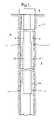
- FIG. 1schematically shows an embodiment of the wellbore system according to the invention, before swelling of the swellable material in the wellbore;
- FIG. 2schematically shows an embodiment of the wellbore system according to the invention, after swelling of the swellable material in the wellbore.
- the annular bodyforms an annular layer provided to the outer surface of the tubular conduit, the annular layer extending continuously along sustantially the lenght of said portion of the tubular conduit surrounded by the salt layer.
- a plurality of particles of resilient materialcan be inserted in the annular space to form a semi-continous resilient annular body.
- said resilient materialis a swellable material susceptible of swelling upon contact with a selected fluid.
- swelling of the resilient material in the annular spaceit is achieved that the resilient material fills up the annular space so that axial flow of wellbore fluid through the annular space is therby prevented.
- the swollen resilient materialcontacts the wellbore wall before significant creep of the salt formation occurs, and any tendency of the wellbore wall to deform non-uniformly is substantially offset by counter-pressure from the swollen resilient material.
- the swellable materialis an elastomer material
- the selected fluidis hydocarbon fluid
- the swellable materialcomprises at least one of the group of natural rubber, nitrile rubber, hydrogenated nitrile rubber, acrylate butadiene rubber, poly acrylate rubber, butyl rubber, brominated butyl rubber, chlorinated butyl rubber, chlorinated polyethylene, neoprene rubber, styrene butadiene copolymer rubber, sulphonated polyethylene, ethylene acrylate rubber, epichlorohydrin ethylene oxide copolymer, ethylene-propylene-copolymer (perioxide croslinked), ethylene-propylrnr-copolymer (sulphur crosslinked), ethylene-propylene-diene terpolymer rubber, ethylene vinyl acetate copolymer, fluoro rubbers, fluoro silicone rubber, and silicone rubbers.
- Preferred swellable materialsare EP(D)M rubber (ethylene-propylene-copolymer rubber, butyl rubber, brominated butyl rubber, chlorinated butyl rubber, and chlorinated polyethylene.
- EP(D)M rubberethylene-propylene-copolymer rubber, butyl rubber, brominated butyl rubber, chlorinated butyl rubber, and chlorinated polyethylene.
- the hydrocarbon fluidis present in a stream of oil based drilling fluid pumped into the wellbore during drilling of the wellbore.
- the resilient materialis an elastomer susceptible of swelling upon contact with oil based drilling fluid, and wherein the wellbore is drilling using said oil based drilling fluid.
- the wellboreis drilled using a water based drilling fluid
- the resilient materialis an elastomer susceptible to swelling upon contact with oil based fluid, ns wherein said oil based fluid is pumped into the annular space so as to replace water based drilling fluid present in the annular space.
- FIG. 1there is shown a wellbore system 1 including a wellbore 2 formed in an earth formation 3 having a salt layer 4 through which the wellbore 2 passes.
- a tubular conduit in the form of wellbore casing 6extends from a wellhead 8 at surface, into the wellbore 2 whereby a portion 10 of the casing 6 extends through the salt layer 4 .
- An annular space 12is formed between the casing 6 and the wellbore wall.
- the portion 10 of casing 6is provided with an annular layer 14 of EPDM rubber which is known to swell when in contact with hydrocarbon fluid, for example oil present in conventional oil based drilling fluid.
- the annular layer 14has an initial thickness significantly smaller than the clearance between the casing 6 and the wellbore wall so as to allow unhampered lowering of the casing 6 with annular layer 14 provided thereto, into the wellbore 2 .
- FIG. 2there is shown the wellbore system 1 after swelling of the annular layer 14 of EPDM rubber due to contact of the layer 14 with oil based drilling fluid present in the wellbore.
- the swollen annular layer 14extends radially against the wellbore annular layer 14 extends radially against the wall formed by the salt formation surrounding the wellbore 2 .
- tha annular space 12vanishes after swelling of the annular layer 14 .
- the wellbore 2is drilled in conventional manner using oil based drilling fluid.
- the casing 6 with the annular layer 14 provided theretois lowered into the wellbore 2 and suspended in a position whereby the annular layer 14 extends substantially the length of the portion of the casing 6 passing through the salt layer 4 .
- the annular layer of EPDM rubberthereby comes into contact with the oil based drilling fluid and starts swelling. Swelling of the layer 14 continues for a period of time which can last several days, until the annular layer 14 completely occupies the annular space 12 and thus becomes biased against the wellbore wall at moderate pressure.
- the salt in salt formation 4 near the wellbore walltends to creep radially inward so that the diameter of the wellbore portion passing through the salt layer 4 reduces slowly.
- a compressive pressurebuilds up in the annular layer 14 of EPDM rubber.
- the saltwill not uniformly creep radially inward along the length of the wellbore section passing through the salt layer 4 .
- Such severe loadingis averted by the rubber annular layer 14 which deforms elastically due to the local load and thereby distributes the loading over a much larger area of the casing.
- the distributed loadis of significantly lower magnitude than the high local loads to which the casing would be subjected in the absence of the annular layer 14 , thus approaching uniform loading of the casing. In this manner it is achieved that failure of the casing due to locally severe loading conditions caused by non-uniform creeping of the salt, is prevented.
- non-uniform creep of the salt along the length of the wellbore portion passing through the salt layer 4is counteracted.
- the swellable elastomergenerates a pressure against the formation which delays the inflow of formation into the wellbore, and serves to spread concentrated loads acting on the casing from irregularities of the hole surface.
- the swelling pressuredecreases with increasing amount of swelling and vice versa, i.e. there is an equilibrium between external pressures and internal pressures associated with the swelling mechanism.
- the salt formationcreeps radially inward and contacts the elastomer, the elastomer becomes locally compressed and exerts a back-pressure to maintain equilibrium.
- the swelling elastomertherefore not only out concentrated loads from the creeping salt formation, but also pushes the salt formation back at a progressively increasing elastic force.
- the annular body of resilient materialincludes an annular body of sand.
Landscapes
- Life Sciences & Earth Sciences (AREA)
- Engineering & Computer Science (AREA)
- Geology (AREA)
- General Life Sciences & Earth Sciences (AREA)
- Mining & Mineral Resources (AREA)
- Environmental & Geological Engineering (AREA)
- Fluid Mechanics (AREA)
- Physics & Mathematics (AREA)
- Geochemistry & Mineralogy (AREA)
- Chemical & Material Sciences (AREA)
- Materials Engineering (AREA)
- Organic Chemistry (AREA)
- Compositions Of Macromolecular Compounds (AREA)
- Rigid Pipes And Flexible Pipes (AREA)
Abstract
Description
Claims (8)
Applications Claiming Priority (4)
| Application Number | Priority Date | Filing Date | Title |
|---|---|---|---|
| EP04257819 | 2004-12-15 | ||
| EP042578195 | 2004-12-15 | ||
| EP04257819 | 2004-12-15 | ||
| PCT/EP2005/056718WO2006063988A1 (en) | 2004-12-15 | 2005-12-13 | Wellbore system extending through a salt layer |
Publications (2)
| Publication Number | Publication Date |
|---|---|
| US20080156492A1 US20080156492A1 (en) | 2008-07-03 |
| US7708081B2true US7708081B2 (en) | 2010-05-04 |
Family
ID=34930920
Family Applications (1)
| Application Number | Title | Priority Date | Filing Date |
|---|---|---|---|
| US11/792,886Active - Reinstated2026-02-24US7708081B2 (en) | 2004-12-15 | 2005-12-13 | Wellbore system extending through a salt layer |
Country Status (6)
| Country | Link |
|---|---|
| US (1) | US7708081B2 (en) |
| EP (1) | EP1825098A1 (en) |
| CN (1) | CN101076652A (en) |
| CA (1) | CA2587939A1 (en) |
| RU (1) | RU2411347C2 (en) |
| WO (1) | WO2006063988A1 (en) |
Cited By (3)
| Publication number | Priority date | Publication date | Assignee | Title |
|---|---|---|---|---|
| US10030467B2 (en) | 2014-03-20 | 2018-07-24 | Saudi Arabian Oil Company | Method and apparatus for sealing an undesirable formation zone in the wall of a wellbore |
| US10844700B2 (en) | 2018-07-02 | 2020-11-24 | Saudi Arabian Oil Company | Removing water downhole in dry gas wells |
| US11555571B2 (en) | 2020-02-12 | 2023-01-17 | Saudi Arabian Oil Company | Automated flowline leak sealing system and method |
Families Citing this family (12)
| Publication number | Priority date | Publication date | Assignee | Title |
|---|---|---|---|---|
| OA13222A (en) | 2003-07-29 | 2006-12-13 | Shell Int Research | System for sealing a space in a wellbore. |
| US7703520B2 (en) | 2008-01-08 | 2010-04-27 | Halliburton Energy Services, Inc. | Sand control screen assembly and associated methods |
| US7712529B2 (en)* | 2008-01-08 | 2010-05-11 | Halliburton Energy Services, Inc. | Sand control screen assembly and method for use of same |
| US7931092B2 (en) | 2008-02-13 | 2011-04-26 | Stowe Woodward, L.L.C. | Packer element with recesses for downwell packing system and method of its use |
| US7994257B2 (en) | 2008-02-15 | 2011-08-09 | Stowe Woodward, Llc | Downwell system with swellable packer element and composition for same |
| US7866383B2 (en)* | 2008-08-29 | 2011-01-11 | Halliburton Energy Services, Inc. | Sand control screen assembly and method for use of same |
| US7841409B2 (en) | 2008-08-29 | 2010-11-30 | Halliburton Energy Services, Inc. | Sand control screen assembly and method for use of same |
| US7814973B2 (en)* | 2008-08-29 | 2010-10-19 | Halliburton Energy Services, Inc. | Sand control screen assembly and method for use of same |
| US20110120733A1 (en) | 2009-11-20 | 2011-05-26 | Schlumberger Technology Corporation | Functionally graded swellable packers |
| US20110220359A1 (en)* | 2010-03-10 | 2011-09-15 | Soliman Mohamed Y | Methods Relating to Modifying Flow Patterns Using In-Situ Barriers |
| CN103032050A (en)* | 2012-12-14 | 2013-04-10 | 湖北双环科技股份有限公司 | Unstable formation treatment technique for rock salt well construction |
| US20240117702A1 (en)* | 2022-10-07 | 2024-04-11 | Halliburton Energy Services, Inc. | Sealing element of isolation device with inner core and outer shell |
Citations (7)
| Publication number | Priority date | Publication date | Assignee | Title |
|---|---|---|---|---|
| US4462714A (en) | 1983-04-04 | 1984-07-31 | The Dow Chemical Company | Method and apparatus for setting a cement plug in the wide-mouth shaft of an earth cavern |
| WO2003008756A1 (en) | 2001-07-18 | 2003-01-30 | Shell Internationale Research Maatschappij B.V. | Wellbore system with annular seal member |
| EP1300545A1 (en) | 2001-10-08 | 2003-04-09 | Services Petroliers Schlumberger | Borehole stabilisation |
| US20040055758A1 (en) | 2002-09-23 | 2004-03-25 | Brezinski Michael M. | Annular isolators for expandable tubulars in wellbores |
| WO2004057715A2 (en) | 2002-12-10 | 2004-07-08 | Rune Freyer | A cable duct device in a swelling packer |
| US20040144538A1 (en) | 2003-01-29 | 2004-07-29 | Richard Bennett M. | Alternative method to cementing casing and liners |
| US20040149431A1 (en)* | 2001-11-14 | 2004-08-05 | Halliburton Energy Services, Inc. | Method and apparatus for a monodiameter wellbore, monodiameter casing and monobore |
Family Cites Families (9)
| Publication number | Priority date | Publication date | Assignee | Title |
|---|---|---|---|---|
| US2814947A (en)* | 1955-07-21 | 1957-12-03 | Union Oil Co | Indicating and plugging apparatus for oil wells |
| SU613084A1 (en)* | 1971-12-14 | 1978-06-30 | Полтавское отделение Украинского научно-исследовательского геологоразведочного института | Method of securing boreholes |
| SU1113515A1 (en)* | 1982-10-04 | 1984-09-15 | Среднеазиатский научно-исследовательский институт природного газа | Method of isolating stratum |
| SU1399452A1 (en)* | 1985-05-13 | 1988-05-30 | Полтавское отделение Украинского научно-исследовательского геологоразведочного института | Method of consolidating wells in cavernous salt deposits |
| SU1541365A1 (en)* | 1987-02-02 | 1990-02-07 | Институт нефти и газа им.И.М.Губкина | Casing string |
| SU1657630A1 (en)* | 1989-06-01 | 1991-06-23 | Туркменский Филиал Всесоюзного Научно-Исследовательского Института Природных Газов | Well completion method |
| US5833647A (en)* | 1995-10-10 | 1998-11-10 | The Penn State Research Foundation | Hydrogels or lipogels with enhanced mass transfer for transdermal drug delivery |
| US6398753B2 (en)* | 1998-04-03 | 2002-06-04 | Mcdaniel David H. | Ultrasound enhancement of percutaneous drug absorption |
| GB2399083B (en)* | 2003-03-07 | 2007-09-19 | Schlumberger Holdings | flexible cementing compositions and methods for high-temperature wells |
- 2005
- 2005-12-13WOPCT/EP2005/056718patent/WO2006063988A1/enactiveApplication Filing
- 2005-12-13CACA002587939Apatent/CA2587939A1/ennot_activeAbandoned
- 2005-12-13RURU2007126853/03Apatent/RU2411347C2/ennot_activeIP Right Cessation
- 2005-12-13EPEP05816091Apatent/EP1825098A1/ennot_activeWithdrawn
- 2005-12-13USUS11/792,886patent/US7708081B2/enactiveActive - Reinstated
- 2005-12-13CNCNA2005800425759Apatent/CN101076652A/enactivePending
Patent Citations (8)
| Publication number | Priority date | Publication date | Assignee | Title |
|---|---|---|---|---|
| US4462714A (en) | 1983-04-04 | 1984-07-31 | The Dow Chemical Company | Method and apparatus for setting a cement plug in the wide-mouth shaft of an earth cavern |
| WO2003008756A1 (en) | 2001-07-18 | 2003-01-30 | Shell Internationale Research Maatschappij B.V. | Wellbore system with annular seal member |
| US7059415B2 (en) | 2001-07-18 | 2006-06-13 | Shell Oil Company | Wellbore system with annular seal member |
| EP1300545A1 (en) | 2001-10-08 | 2003-04-09 | Services Petroliers Schlumberger | Borehole stabilisation |
| US20040149431A1 (en)* | 2001-11-14 | 2004-08-05 | Halliburton Energy Services, Inc. | Method and apparatus for a monodiameter wellbore, monodiameter casing and monobore |
| US20040055758A1 (en) | 2002-09-23 | 2004-03-25 | Brezinski Michael M. | Annular isolators for expandable tubulars in wellbores |
| WO2004057715A2 (en) | 2002-12-10 | 2004-07-08 | Rune Freyer | A cable duct device in a swelling packer |
| US20040144538A1 (en) | 2003-01-29 | 2004-07-29 | Richard Bennett M. | Alternative method to cementing casing and liners |
Non-Patent Citations (2)
| Title |
|---|
| Pattillo, P. et al: "Effect of Nonuniform Loading on Conventional Collapse Resistance", Sep. 2004, pp. 156-163. |
| Wilson, S. et al: "Assessment of Salt Loading on Well Casings", Mar. 1, 2003, pp. 13-14. |
Cited By (7)
| Publication number | Priority date | Publication date | Assignee | Title |
|---|---|---|---|---|
| US10030467B2 (en) | 2014-03-20 | 2018-07-24 | Saudi Arabian Oil Company | Method and apparatus for sealing an undesirable formation zone in the wall of a wellbore |
| US10087708B2 (en) | 2014-03-20 | 2018-10-02 | Saudi Arabian Oil Company | Sealing an undesirable formation zone in the wall of a wellbore |
| US10280705B2 (en) | 2014-03-20 | 2019-05-07 | Saudi Arabian Oil Company | Sealing an undesirable formation zone in the wall of a wellbore |
| US10458199B2 (en) | 2014-03-20 | 2019-10-29 | Saudi Arabian Oil Company | Sealing an undesirable formation zone in the wall of a wellbore |
| US10494894B2 (en) | 2014-03-20 | 2019-12-03 | Saudi Arabian Oil Company | Sealing an undesirable formation zone in the wall of a wellbore |
| US10844700B2 (en) | 2018-07-02 | 2020-11-24 | Saudi Arabian Oil Company | Removing water downhole in dry gas wells |
| US11555571B2 (en) | 2020-02-12 | 2023-01-17 | Saudi Arabian Oil Company | Automated flowline leak sealing system and method |
Also Published As
| Publication number | Publication date |
|---|---|
| RU2007126853A (en) | 2009-01-27 |
| US20080156492A1 (en) | 2008-07-03 |
| RU2411347C2 (en) | 2011-02-10 |
| CA2587939A1 (en) | 2006-06-22 |
| WO2006063988A1 (en) | 2006-06-22 |
| CN101076652A (en) | 2007-11-21 |
| EP1825098A1 (en) | 2007-08-29 |
Similar Documents
| Publication | Publication Date | Title |
|---|---|---|
| US7708081B2 (en) | Wellbore system extending through a salt layer | |
| AU2011202331B2 (en) | Swellable packer anchors | |
| EP1805391B1 (en) | Downhole swellable seal | |
| US7228915B2 (en) | Device and method to seal boreholes | |
| US7328742B2 (en) | Seal cup for a wellbore tool and method | |
| CA2701489C (en) | Improvements to swellable apparatus | |
| US7059415B2 (en) | Wellbore system with annular seal member | |
| CA2556517C (en) | Packer having a seal and a support member for the seal | |
| US20090200043A1 (en) | Vented packer element for downwell packing system | |
| US20100126722A1 (en) | Wellbore system and method of completing a wellbore | |
| RU2664079C2 (en) | Swellable packer, system and method for use thereof | |
| US20090205818A1 (en) | Downwell system with swellable packer including blowing agent | |
| US20200340314A1 (en) | Downhole Check Valve Assembly with a Swellable Element Mechanism | |
| CN109138940A (en) | Well completion pipe string | |
| US20250314145A1 (en) | Packer assembly with expandable spacer | |
| CN114439409A (en) | Packer (CN) |
Legal Events
| Date | Code | Title | Description |
|---|---|---|---|
| AS | Assignment | Owner name:SHELL OIL COMPANY, TEXAS Free format text:ASSIGNMENT OF ASSIGNORS INTEREST;ASSIGNORS:BOSMA, MARTIN GERARD RENE;CORNELISSEN, ERIK KERST;REEL/FRAME:019906/0343;SIGNING DATES FROM 20070516 TO 20070523 Owner name:SHELL OIL COMPANY,TEXAS Free format text:ASSIGNMENT OF ASSIGNORS INTEREST;ASSIGNORS:BOSMA, MARTIN GERARD RENE;CORNELISSEN, ERIK KERST;SIGNING DATES FROM 20070516 TO 20070523;REEL/FRAME:019906/0343 | |
| FPAY | Fee payment | Year of fee payment:4 | |
| FEPP | Fee payment procedure | Free format text:MAINTENANCE FEE REMINDER MAILED (ORIGINAL EVENT CODE: REM.) | |
| LAPS | Lapse for failure to pay maintenance fees | Free format text:PATENT EXPIRED FOR FAILURE TO PAY MAINTENANCE FEES (ORIGINAL EVENT CODE: EXP.) | |
| STCH | Information on status: patent discontinuation | Free format text:PATENT EXPIRED DUE TO NONPAYMENT OF MAINTENANCE FEES UNDER 37 CFR 1.362 | |
| FP | Lapsed due to failure to pay maintenance fee | Effective date:20180504 | |
| AS | Assignment | Owner name:SWELLFIX B.V., NETHERLANDS Free format text:ASSIGNMENT OF ASSIGNORS INTEREST;ASSIGNOR:SHELL OIL COMPANY;REEL/FRAME:047124/0227 Effective date:20180115 Owner name:SWELLFIX UK LIMITED, UNITED KINGDOM Free format text:ASSIGNMENT OF ASSIGNORS INTEREST;ASSIGNOR:SWELLFIX B.V.;REEL/FRAME:047124/0638 Effective date:20180809 | |
| FEPP | Fee payment procedure | Free format text:SURCHARGE, PETITION TO ACCEPT PYMT AFTER EXP, UNINTENTIONAL (ORIGINAL EVENT CODE: M1558); ENTITY STATUS OF PATENT OWNER: LARGE ENTITY Free format text:PETITION RELATED TO MAINTENANCE FEES FILED (ORIGINAL EVENT CODE: PMFP); ENTITY STATUS OF PATENT OWNER: LARGE ENTITY | |
| MAFP | Maintenance fee payment | Free format text:PAYMENT OF MAINTENANCE FEE, 8TH YEAR, LARGE ENTITY (ORIGINAL EVENT CODE: M1552); ENTITY STATUS OF PATENT OWNER: LARGE ENTITY Year of fee payment:8 | |
| FEPP | Fee payment procedure | Free format text:11.5 YR SURCHARGE- LATE PMT W/IN 6 MO, LARGE ENTITY (ORIGINAL EVENT CODE: M1556); ENTITY STATUS OF PATENT OWNER: LARGE ENTITY | |
| MAFP | Maintenance fee payment | Free format text:PAYMENT OF MAINTENANCE FEE, 12TH YEAR, LARGE ENTITY (ORIGINAL EVENT CODE: M1553); ENTITY STATUS OF PATENT OWNER: LARGE ENTITY Year of fee payment:12 | |
| FEPP | Fee payment procedure | Free format text:PETITION RELATED TO MAINTENANCE FEES DISMISSED (ORIGINAL EVENT CODE: PMFS); ENTITY STATUS OF PATENT OWNER: LARGE ENTITY | |
| FEPP | Fee payment procedure | Free format text:PETITION RELATED TO MAINTENANCE FEES FILED (ORIGINAL EVENT CODE: PMFP); ENTITY STATUS OF PATENT OWNER: LARGE ENTITY | |
| FEPP | Fee payment procedure | Free format text:PETITION RELATED TO MAINTENANCE FEES FILED (ORIGINAL EVENT CODE: PMFP); ENTITY STATUS OF PATENT OWNER: LARGE ENTITY | |
| PRDP | Patent reinstated due to the acceptance of a late maintenance fee | Effective date:20230525 | |
| FEPP | Fee payment procedure | Free format text:PETITION RELATED TO MAINTENANCE FEES GRANTED (ORIGINAL EVENT CODE: PMFG); ENTITY STATUS OF PATENT OWNER: LARGE ENTITY | |
| STCF | Information on status: patent grant | Free format text:PATENTED CASE |