US7707818B2 - Exhaust stacks and power generation systems for increasing gas turbine power output - Google Patents
Exhaust stacks and power generation systems for increasing gas turbine power outputDownload PDFInfo
- Publication number
- US7707818B2 US7707818B2US12/029,162US2916208AUS7707818B2US 7707818 B2US7707818 B2US 7707818B2US 2916208 AUS2916208 AUS 2916208AUS 7707818 B2US7707818 B2US 7707818B2
- Authority
- US
- United States
- Prior art keywords
- exhaust gases
- silencer
- flow path
- sectional flow
- tubular portion
- Prior art date
- Legal status (The legal status is an assumption and is not a legal conclusion. Google has not performed a legal analysis and makes no representation as to the accuracy of the status listed.)
- Expired - Fee Related, expires
Links
Images


Classifications
- F—MECHANICAL ENGINEERING; LIGHTING; HEATING; WEAPONS; BLASTING
- F23—COMBUSTION APPARATUS; COMBUSTION PROCESSES
- F23J—REMOVAL OR TREATMENT OF COMBUSTION PRODUCTS OR COMBUSTION RESIDUES; FLUES
- F23J11/00—Devices for conducting smoke or fumes, e.g. flues
- F23J11/12—Smoke conduit systems for factories or large buildings
- F—MECHANICAL ENGINEERING; LIGHTING; HEATING; WEAPONS; BLASTING
- F01—MACHINES OR ENGINES IN GENERAL; ENGINE PLANTS IN GENERAL; STEAM ENGINES
- F01D—NON-POSITIVE DISPLACEMENT MACHINES OR ENGINES, e.g. STEAM TURBINES
- F01D25/00—Component parts, details, or accessories, not provided for in, or of interest apart from, other groups
- F01D25/30—Exhaust heads, chambers, or the like
- F—MECHANICAL ENGINEERING; LIGHTING; HEATING; WEAPONS; BLASTING
- F02—COMBUSTION ENGINES; HOT-GAS OR COMBUSTION-PRODUCT ENGINE PLANTS
- F02C—GAS-TURBINE PLANTS; AIR INTAKES FOR JET-PROPULSION PLANTS; CONTROLLING FUEL SUPPLY IN AIR-BREATHING JET-PROPULSION PLANTS
- F02C7/00—Features, components parts, details or accessories, not provided for in, or of interest apart form groups F02C1/00 - F02C6/00; Air intakes for jet-propulsion plants
- F02C7/24—Heat or noise insulation
- F—MECHANICAL ENGINEERING; LIGHTING; HEATING; WEAPONS; BLASTING
- F23—COMBUSTION APPARATUS; COMBUSTION PROCESSES
- F23J—REMOVAL OR TREATMENT OF COMBUSTION PRODUCTS OR COMBUSTION RESIDUES; FLUES
- F23J13/00—Fittings for chimneys or flues
- F23J13/06—Mouths; Inlet holes
- F—MECHANICAL ENGINEERING; LIGHTING; HEATING; WEAPONS; BLASTING
- F23—COMBUSTION APPARATUS; COMBUSTION PROCESSES
- F23L—SUPPLYING AIR OR NON-COMBUSTIBLE LIQUIDS OR GASES TO COMBUSTION APPARATUS IN GENERAL ; VALVES OR DAMPERS SPECIALLY ADAPTED FOR CONTROLLING AIR SUPPLY OR DRAUGHT IN COMBUSTION APPARATUS; INDUCING DRAUGHT IN COMBUSTION APPARATUS; TOPS FOR CHIMNEYS OR VENTILATING SHAFTS; TERMINALS FOR FLUES
- F23L11/00—Arrangements of valves or dampers after the fire
- F23L11/02—Arrangements of valves or dampers after the fire for reducing draught by admission of air to flues
- F—MECHANICAL ENGINEERING; LIGHTING; HEATING; WEAPONS; BLASTING
- F23—COMBUSTION APPARATUS; COMBUSTION PROCESSES
- F23J—REMOVAL OR TREATMENT OF COMBUSTION PRODUCTS OR COMBUSTION RESIDUES; FLUES
- F23J2900/00—Special arrangements for conducting or purifying combustion fumes; Treatment of fumes or ashes
- F23J2900/13003—Means for reducing the noise in smoke conducing ducts or systems
- Y—GENERAL TAGGING OF NEW TECHNOLOGICAL DEVELOPMENTS; GENERAL TAGGING OF CROSS-SECTIONAL TECHNOLOGIES SPANNING OVER SEVERAL SECTIONS OF THE IPC; TECHNICAL SUBJECTS COVERED BY FORMER USPC CROSS-REFERENCE ART COLLECTIONS [XRACs] AND DIGESTS
- Y02—TECHNOLOGIES OR APPLICATIONS FOR MITIGATION OR ADAPTATION AGAINST CLIMATE CHANGE
- Y02E—REDUCTION OF GREENHOUSE GAS [GHG] EMISSIONS, RELATED TO ENERGY GENERATION, TRANSMISSION OR DISTRIBUTION
- Y02E20/00—Combustion technologies with mitigation potential
- Y02E20/16—Combined cycle power plant [CCPP], or combined cycle gas turbine [CCGT]
Definitions
- the present applicationrelates generally to gas turbines, and more specifically to exhaust stacks and power generation systems configured to increase the power output of gas turbines.
- a combined cycle power plant(“CCPP”) includes a gas turbine, a heat recovery steam generator (“HRSG”), a steam turbine and an exhaust stack.
- the gas turbineincludes a turbine configured to produce a rotational power output in response to an expansion of exhaust gases.
- the HRSGis configured to receive the exhaust gases from the gas turbine and generate steam from heat of the exhaust gases.
- the steam turbineis configured to produce a rotational power output in response to an expansion of the steam.
- the exhaust stackis configured to pass the exhaust gases from the HRSG to the atmosphere.
- the gas turbineincludes a compressor, a combustion region and the turbine.
- the compressoris configured to compress an inflow of air.
- the combustion regionis configured to receive the compressed air, combust a mixture of the compressed air and fuel, and produce a high temperature, high pressure exhaust gases.
- the turbineis configured to receive the exhaust gases and rotate in response to the expansion of the exhaust gases. Accordingly, the rotational power output of the turbine is proportional to the expansion of the exhaust gases and inherent pressure drop.
- an exhaust stackconfigured to reduce the local pressure drop through the exhaust stack, such that the expansion of the exhaust gases in the gas turbine is increased and hence the power output of the gas turbine is increased.
- the exhaust stackincludes a junction tube.
- the exhaust stackfurther includes a flue having a silencer portion, a converging duct portion, a tubular portion, and a diverging diffuser portion.
- the silencer portionfluidly communicates with the junction tube. At least a portion of the silencer portion has a first hydraulic mean cross-sectional flow path, and at least a portion of the tubular portion has a second hydraulic mean cross-sectional flow path less than or equal to the first hydraulic mean cross-sectional flow path.
- the converging duct portionis coupled between the silencer portion and the tubular portion.
- the diverging diffuser portionis coupled to an end of the tubular portion opposite to the converging duct portion, such that exhaust gases flowing through the junction tube, the silencer portion, the converging duct portion, the tubular portion and the diverging diffuser portion, has a reduced localized pressure drop, at least in part due to the diverging diffuser portion, and the second hydraulic mean cross-sectional flow path being less than or equal to the first hydraulic mean cross-sectional flow path.
- the power generation systemincludes a gas turbine having a compressor, a combustion region and a turbine.
- the compressoris configured to compress air.
- the combustion regionis configured to receive the compressed air from the compressor and combust a mixture of the compressed air and fuel, which produces exhaust gases.
- the turbineis configured to receive the exhaust gases from the combustion region and rotate in response to an expansion of the exhaust gases, such that a pressure of the exhaust gases decreases as the exhaust gases expands through the turbine.
- the power generation systemfurther includes a heat recovery steam generator configured to receive the exhaust gases and generate steam from heat of the exhaust gases.
- the power generation systemfurther includes an exhaust stack having a junction tube and a flue. The junction tube is configured to receive the exhaust gases from the heat recovery steam generator.
- the fluehas a silencer portion, a converging duct portion, a tubular portion, and a diverging diffuser portion.
- the silencer portionfluidly communicates with the junction tube. At least a portion of the silencer portion has a first hydraulic mean cross-sectional flow path, and at least a portion of the tubular portion has a second hydraulic mean cross-sectional flow path less than or equal to the first hydraulic mean cross-sectional flow path.
- the converging duct portionis coupled between the silencer portion and the tubular portion.
- the diverging diffuser portionis coupled to an end of the tubular portion opposite to the converging duct portion, such that exhaust gases flowing through the junction tube, the silencer portion, the converging duct portion, the tubular portion and the diverging diffuser portion, has a reduced localized pressure drop, at least in part due to the diverging diffuser portion, and the second hydraulic mean cross-sectional flow path being less than or equal to the first hydraulic mean cross-sectional flow path.
- the reduced localized pressure drop in the exhaust stackincreases the overall pressure differential of the exhaust gases across the turbine and hence increases the power output of the gas turbine.
- the exhaust stackincludes a junction tube.
- the exhaust stackfurther includes a flue having a first tubular portion, a first diverging diffuser portion, a silencer portion, a converging duct portion, a second tubular portion, and a second diverging diffuser portion.
- the first tubular portionfluidly communicates with the junction tube.
- At least a portion of the first tubular portionhas a first hydraulic mean cross-sectional flow path
- at least a portion of the silencer portionhas a second hydraulic mean cross-sectional flow path.
- the first hydraulic mean cross-sectional flow pathis less than or equal to the second hydraulic mean cross-sectional flow path.
- the first diverging diffuser portionis coupled between the first tubular portion and the silencer portion.
- At least a portion of the second tubular portionhas a third hydraulic mean cross-sectional flow path less than or equal to the second hydraulic mean cross-sectional flow path.
- the converging duct portionis coupled between the silencer portion and the second tubular portion.
- the second diverging diffuser portionis coupled to an end of the second tubular portion opposite to the converging duct portion, such that exhaust gases flowing through the junction tube, the first tubular portion, the first diverging diffuser portion, the silencer portion, the converging duct portion, the second tubular portion and the second diverging diffuser portion, have a reduced localized pressure drop, at least in part due to the second diverging diffuser portion, and the third hydraulic mean cross-sectional flow path being less than or equal to the second hydraulic mean cross-sectional flow path.
- the power generation systemincludes a gas turbine having a compressor, a combustion region and a turbine.
- the compressoris configured to compress air.
- the combustion regionis configured to receive the compressed air from the compressor and combust a mixture of the compressed air and fuel which produces exhaust gases.
- the turbineis configured to receive the exhaust gases from the combustion region and rotate in response to an expansion of the exhaust gases, such that a pressure of the exhaust gases decreases as the exhaust gases expands through the turbine.
- the power generation systemfurther includes a heat recovery steam generator configured to receive the exhaust gases and generate steam from heat of the exhaust gases.
- the power generation systemfurther includes an exhaust stack having a junction tube and a flue. The junction tube is configured to receive the exhaust gases from the heat recovery steam generator.
- the fluehas a first tubular portion, a first diverging diffuser portion, a silencer portion, a converging duct portion, a second tubular portion, and a second diverging diffuser portion.
- the first tubular portionfluidly communicates with the junction tube. At least a portion of the first tubular portion has a first hydraulic mean cross-sectional flow path. At least a portion of the silencer portion has a second hydraulic mean cross-sectional flow path. The first hydraulic mean cross-sectional flow path is less than or equal to the first hydraulic mean cross-sectional flow path.
- the first diverging diffuser portionis coupled between the first tubular portion and the silencer portion.
- At least a portion of the second tubular portionhas a third hydraulic mean cross-sectional flow path less than or equal to the second hydraulic mean cross-sectional flow path.
- the converging duct portionis coupled between the silencer portion and the second tubular portion.
- the second diverging diffuser portionis coupled to an end of the second tubular portion opposite to the converging duct portion, such that exhaust gases flowing through the junction tube, the first tubular portion, the first diverging diffuser portion, the silencer portion, the converging duct portion, the second tubular portion and the second diverging diffuser portion have a reduced overall pressure drop, at least in part due to the second diverging diffuser portion, and the third hydraulic mean cross-sectional flow path being less than or equal to the second hydraulic mean cross-sectional flow path.
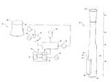
- FIG. 1is a schematic of a combined cycle power generation system having an exhaust stack, in accordance with an exemplary embodiment
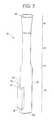
- FIG. 2is a perspective view of the exhaust stack of FIG. 1 ;
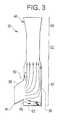
- FIG. 3is a flow profile for the exhaust stack of FIG. 2 ;
- FIG. 4is a cross-sectional view of the exhaust stack of FIG. 2 ;
- FIG. 5is an enlarged cross-sectional view of a diverging diffuser portion of the exhaust stack of FIG. 2 ;
- FIG. 6is a cross-sectional view of an exhaust stack showing a top surface of a junction tube extending from a silencer portion by an angle within a range between about 90 and about 135 degrees, and a bottom surface of the junction tube extending from the silencer portion by an angle within a range between about 22.5 and about 67.5 degrees, in accordance with another exemplary embodiment;
- FIG. 7is a cross-sectional view of an exhaust stack showing a top surface of a junction tube extending from a silencer portion by an angle within a range between about 90 and about 135 degrees, a bottom surface of the junction tube extending from the silencer portion by an angle within a range between about 22.5 and about 67.5 degrees, and a flow guider having a planar surface positioned at an angle within a range between about 22.5 and about 67.5 degrees from a lateral axis 272 of the exhaust stack, in accordance with yet another exemplary embodiment;
- FIG. 8is a cross-sectional view of an exhaust stack showing a top surface of a junction tube extending from a silencer portion by an angle within a range between about 90 and about 135 degrees, a bottom surface of the junction tube extending from the silencer portion by an angle within a range between about 22.5 and about 67.5 degrees, and a flow guider having a concave surface extending from a lateral axis of the exhaust stack by an angle within a range between about 22.5 and about 67.5 degrees, in accordance with another exemplary embodiment; and
- FIG. 9is a cross-sectional view of an exhaust stack, in accordance with another exemplary embodiment.
- Exemplary embodimentsare directed to an exhaust stack configured to increase a power output of a gas turbine of a combined cycle power plant (“CCPP”).
- CCPPcombined cycle power plant
- the exhaust stackcan increase the power output of gas turbines integrated in other suitable power generation systems.
- the exhaust stackis configured to reduce the pressure drop in the exhaust stack in order to increase the pressure drop associated with the expansion of the exhaust gases in the gas turbine, such that the increased expansion of gas increases the power output of the gas turbine.
- a CCPP 10includes a gas turbine generator 12 and a steam turbine generator 14 .
- the gas turbine generator 12is configured to generate electricity and produce exhaust gases.
- the steam turbine generator 14is configured to receive the exhaust gases from the gas turbine generator 12 and generate additional electricity from waste heat of the exhaust gases.
- the gas turbine generator 12includes a gas turbine 16 , a first output shaft 18 and a first electrical generator 20 .
- the gas turbine 16has a compressor 22 , a combustion region 24 and a turbine 26 .
- the compressor 22is configured to compress an inflow of air.
- the combustion region 24is configured to receive the compressed air from the compressor 22 and combust a mixture of the compressed air and fuel, which produces a high pressure, high temperature exhaust gases.
- the turbine 26is configured to receive the exhaust gases from the combustion region 24 and rotate in response to an expansion of the exhaust gases.
- the turbine 26is operably connected to the first electrical generator 20 by the first output shaft 18 for providing rotational power to the first electrical generator 20 and producing electricity.
- the turbine 26is further configured to pass the exhaust gases to the steam turbine generator 14 .
- the steam turbine generator 14includes a HRSG 28 and an exhaust stack 30 .
- the HRSG 28is configured to receive the exhaust gases from the gas turbine 16 and generate steam from the waste heat of the exhaust gases.
- the exhaust stack 30is configured to pass the exhaust gases from the HRSG 28 to the atmosphere and reduce the local pressure drop of the exhaust gases in the stack and increase the overall pressure differential across the turbine, as described in detail below.
- the steam turbine generator 14further includes a steam turbine 32 , a second output shaft 34 , a second electrical generator 36 , a condenser 38 , a cooling tower 40 and a pump 42 .
- the steam turbine 32is configured to receive the steam from the HRSG 28 and rotate in response to the expansion of steam.
- the steam turbine 32is operably connected to the second electrical generator 36 by the second output shaft 34 for providing rotational power to the second electrical generator 36 and generating electricity.
- the steam turbine 32can instead be operably connected to the first electrical generator 20 by the first output shaft 18 in a single shaft arrangement.
- the condenser 38is configured to receive the steam from the steam turbine 32 and condense the steam into water.
- the condenser 38is configured to receive water from the cooling tower 40 and transfer heat from the steam to the water and condense the steam into water. It is contemplated that the condenser 38 can instead be configured to transfer heat to water from a lake, river, sea or other suitable non-limiting examples.
- the pump 42is configured to pump water from the condenser 38 into the HRSG 28 .
- the exhaust stack 30includes a junction tube 44 and a flue 46 .
- the junction tube 44is configured to fluidly communicate with the HRSG 28 .
- the flue 46includes a silencer portion 48 , a converging duct portion 50 , a tubular portion 52 and a diverging diffuser portion 54 .
- the silencer portion 48is configured to fluidly communicate with the junction tube 44 . At least a portion of the silencer portion 48 has a first hydraulic mean cross-sectional flow path, and at least a portion of the tubular portion 52 has a second hydraulic mean cross-sectional flow path less than or equal to the first hydraulic mean cross-sectional flow path.
- the converging duct portion 50is coupled between the silencer portion 48 and the tubular portion 52 .
- the diverging diffuser portion 54is coupled to an end of the tubular portion 52 opposite to the converging duct portion 50 . Accordingly, the exhaust gases flowing through the junction tube 44 , the silencer portion 48 , the converging duct portion 50 , the tubular portion 52 and the diverging diffuser portion 54 , have a reduced overall pressure drop at least in part due to the diverging diffuser portion 54 and the second hydraulic mean cross-sectional flow path being less than or equal to the first hydraulic mean cross-sectional flow path.
- the junction tube 44has a top surface 56 and a bottom surface 58 extending from an outer surface 60 of the silencer portion 48 , such that the junction tube 44 provides a uniform flow distribution into the silencer portion 48 for reducing a localized pressure drop into the silencer portion.
- the top surface 56extends from the outer surface 60 of the silencer portion 48 by 135 degrees
- the bottom surface 58extends from the outer surface 60 by 45 degrees.
- the junction tube 44directs the exhaust gases through the silencer portion 48 towards the converging duct portion 50 , with a substantially uniform flow profile for reducing pressure drop in the silencer section.
- the junction tube 44also reduces a turning loss at a closed end 62 of the silencer portion 48 and enhances the pressure recovery in the diverging diffuser portion 54 .
- top surface 56 and the bottom surface 58 of the junction tube 44can extend from the outer surface 60 of the silencer portion 48 by various suitable angles, as exemplified in the embodiments of FIGS. 6-9 .
- the diverging diffuser portion 54is configured to diverge from the tubular portion 52 , such that the diverging diffuser portion 54 recovers exit pressure loss.
- a divergence angle ⁇include 5 degrees, 15 degrees and suitable angles in the range therebetween, in order to recover pressure in the range between about 1.5 and 2.0 centimeters of water for a velocity range between about 18 and about 22 meters per second. It is contemplated that the divergence angle can be greater or less than this range, utilizing a suitable pressure recovery device.
- the diverging diffuser portion 54further includes a first end 64 with a diameter of 6 meters and a second end 66 with a diameter of 9 meters. It is understood that the diameters of the first end 64 and second end 66 can be greater or less than 6 and 9 meters, respectively.
- the diverging diffuser portion 54has a length of 15 meters from the first end 64 to the second end 66 . However, the diverging diffuser portion 54 can have a length greater or less than 15 meters.
- an exhaust stack 130 having a junction tube 144 and a flue 146 with a silencer portion 148 , a converging duct portion 150 , a tubular portion 152 and a diverging diffuser portion 154is substantially similar to the exhaust stack 30 having the junction tube 44 and the flue 46 with the silencer portion 48 , the converging duct portion 50 , the tubular portion 52 and the diverging diffuser portion 54 of FIGS. 1-4 .
- the junction tube 144has a top surface 156 that can extend from an outer surface 160 of the silencer portion 148 by an angle within the range between about 90 and about 135 degrees.
- the junction tube 144has a bottom surface 158 that extends from the outer surface 160 by an angle within a range between about 22.5 and about 67.5 degrees.
- an exhaust stack 230 having a junction tube 244 and a flue 246 with a silencer portion 248 , a converging duct portion 250 , a tubular portion 252 and an diverging diffuser portion 254is substantially similar to the exhaust stack 30 respectively having the junction tube 44 and the flue 46 with the silencer portion 48 , the converging duct portion 50 , the tubular portion 52 and the diverging diffuser portion 54 of FIGS. 1-4 .
- the junction tube 244has a top surface 256 that extends from the outer surface 260 by an angle within the range between about 90 and about 135 degrees.
- the junction tube 244has a bottom surface 258 that extends from the outer surface 260 by an angle within a range between about 22.5 and about 67.5 degrees.
- the flue 246further includes a flow guider 268 configured to reduce turning loss at a closed end 262 of the silencer portion 248 and to provide a substantially uniform velocity flow profile upstream of silencer portion 248 and diffuser portion 246 .
- the flow guider 268is a plate having a planar surface extending from the bottom surface 258 of the silencer portion 248 and across a cavity 270 of the silencer portion 248 .
- the planar surface of the flow guider 268is positioned at an angle within a range between about 22.5 and about 67.5 degrees from a lateral axis 272 of the flue 246 . In that regard, a significant portion of exhaust gases is directed away from the closed end 262 of the silencer portion 248 and towards the converging duct portion 250 .
- the silencer portion 248is configured to allow for the expansion of the exhaust gases and reduce the velocity and the turbulence of the exhaust gases, such that high energy noise is dissipated in the silencer portion 248 .
- the silencer portion 248is configured to have a first mean velocity of exhaust gases flowing therethrough and the tubular portion 252 is configured to have a second mean velocity of exhaust gases flowing therethrough.
- the first mean velocityis equal to at least one-half the second mean velocity.
- an exhaust stack 330 having a junction tube 344 and a flue 346 with a silencer portion 348 , a converging duct portion 350 , a tubular portion 352 and an diverging diffuser portion 354is substantially similar to the exhaust stack 30 having the junction tube 44 and the flue 46 with the silencer portion 48 , the converging duct portion 50 , the tubular portion 52 and the diverging diffuser portion 54 of FIGS. 1-4 .
- the junction tube 344has a top surface 356 that extends from an outer surface 360 of the silencer portion 348 by an angle within a range between about 90 and about 135 degrees.
- the junction tube 344has a bottom surface 358 that extends from the outer surface 360 by an angle within a range between about 22.5 and about 67.5 degrees.
- the flue 346further includes a flow guider 368 configured to reduce turning loss at a closed end 362 of the silencer portion 348 and provide substantially uniform velocity profile at the silencer inlet and diffuser inlet section ensuring maximum pressure recovery.
- the flow guider 368is a plate having a concave surface extending from the bottom surface 358 of the silencer portion 348 and across a cavity 370 of the silencer portion 348 .
- the concave surfacehas a radius of curvature equal to one-half of the first diameter of the silencer portion 48 .
- the concave surfacecan instead have other suitable radii of curvatures.
- the flow guider 368is positioned at an angle within a range between about 22.5 and about 67.5 degrees from a lateral axis 372 of the flue 346 .
- an exhaust stack 400is configured to limit the pressure drop of the exhaust gases to approximately 0.5 inches of water.
- the exhaust stack 400includes a junction tube 402 and a flue 404 .
- the junction tube 402fluidly communicates with the HRSG 28 and is configured to receive steam from the HRSG 28 .
- the flue 404includes a first tubular portion 406 , a first diverging diffuser portion 408 , a silencer portion 410 , a converging duct portion 412 , a second tubular portion 414 , and a second diverging diffuser portion 416 .
- the first tubular portion 406fluidly communicates with the junction tube 402 .
- the first tubular portion 406has a first hydraulic mean cross-sectional flow path
- the silencer portion 410has a second hydraulic mean cross-sectional flow path.
- the first hydraulic mean cross-sectional flow pathis less than or equal to the second hydraulic mean cross-sectional flow path.
- the first diverging diffuser portion 408is coupled between the first tubular portion 406 and the silencer portion 410 .
- the second tubular portion 414has a third hydraulic mean cross-sectional flow path less than or equal to the second hydraulic mean cross-sectional flow path.
- the converging duct portion 412is coupled between the silencer portion 410 and the second tubular portion 414 .
- the second diverging diffuser portion 416is coupled to an end of the second tubular portion 414 opposite to the converging duct portion 412 , such that exhaust gases flowing through the junction tube 402 , the first tubular portion 406 , the first diverging diffuser portion 408 , the silencer portion 410 , the converging duct portion 412 , the second tubular portion 414 and the second diverging diffuser portion 416 has a reduced overall pressure drop, at least in part due to the second diverging diffuser portion and the third hydraulic mean cross-sectional flow path being less than or equal to the second hydraulic mean cross-sectional flow path.
- the reduced localized stack pressure dropincreases an overall pressure differential of the exhaust gases through the gas turbine 16 and increases a power output of the gas turbine 16 .
- the first tubular portion 406 , silencer portion 410 and second tubular portion 414are configured to have first, second, and third mean velocities, respectively, of exhaust gases flowing therethrough.
- the first mean velocityis at least equal to an average of the second and third mean velocities.
- the second mean velocityis equal to at least one-half the third mean velocity.
- the silencer portion 410is further configured to allow for the expansion of the exhaust gases and reduce the velocity and the turbulence of the exhaust gases, such that high-energy noise is dissipated in the silencer portion 410 .
- the flue 404further includes a flow guider 468 configured to reduce turning loss at a closed end 462 of the silencer portion 410 and to provide a substantially uniform velocity profile upstream of the silencer section and diffuser section.
- the flow guider 468is a plate having a planar surface extending from the bottom surface 462 of the silencer portion 410 and across a cavity 470 of the silencer portion 410 .
- the flow guider 468is positioned at an angle within the range of about 22.5 degrees and about 67.5 degrees from a lateral axis 472 of the flue 404 .
- the exhaust stacks and methods described hereinprovide a substantial advantage over other devices and methods.
- the exhaust stacksprovide a technical effect of reducing a pressure drop of exhaust gases and increasing an amount of power output by a gas turbine.
- the terms hydraulic mean cross-sectional flow pathrefers to a mean or average cross-sectional size of a flow path.
Landscapes
- Engineering & Computer Science (AREA)
- Mechanical Engineering (AREA)
- General Engineering & Computer Science (AREA)
- Chemical & Material Sciences (AREA)
- Combustion & Propulsion (AREA)
- Architecture (AREA)
- Exhaust Silencers (AREA)
- Engine Equipment That Uses Special Cycles (AREA)
Abstract
Description
Claims (18)
Priority Applications (5)
| Application Number | Priority Date | Filing Date | Title |
|---|---|---|---|
| US12/029,162US7707818B2 (en) | 2008-02-11 | 2008-02-11 | Exhaust stacks and power generation systems for increasing gas turbine power output |
| CH00185/09ACH698471A2 (en) | 2008-02-11 | 2009-02-09 | Vent for increasing the output power of a gas turbine. |
| JP2009027980AJP2009185820A (en) | 2008-02-11 | 2009-02-10 | Exhaust stack for enhancing gas turbine output and power generating system |
| DE102009003461ADE102009003461A1 (en) | 2008-02-11 | 2009-02-10 | Exhaust chimneys and energy generation systems for increasing the energy output of gas turbines |
| CN200910004139.2ACN101509427A (en) | 2008-02-11 | 2009-02-11 | Exhaust stacks and power generation systems for increasing gas turbine power output |
Applications Claiming Priority (1)
| Application Number | Priority Date | Filing Date | Title |
|---|---|---|---|
| US12/029,162US7707818B2 (en) | 2008-02-11 | 2008-02-11 | Exhaust stacks and power generation systems for increasing gas turbine power output |
Publications (2)
| Publication Number | Publication Date |
|---|---|
| US20090199558A1 US20090199558A1 (en) | 2009-08-13 |
| US7707818B2true US7707818B2 (en) | 2010-05-04 |
Family
ID=40847490
Family Applications (1)
| Application Number | Title | Priority Date | Filing Date |
|---|---|---|---|
| US12/029,162Expired - Fee RelatedUS7707818B2 (en) | 2008-02-11 | 2008-02-11 | Exhaust stacks and power generation systems for increasing gas turbine power output |
Country Status (5)
| Country | Link |
|---|---|
| US (1) | US7707818B2 (en) |
| JP (1) | JP2009185820A (en) |
| CN (1) | CN101509427A (en) |
| CH (1) | CH698471A2 (en) |
| DE (1) | DE102009003461A1 (en) |
Cited By (3)
| Publication number | Priority date | Publication date | Assignee | Title |
|---|---|---|---|---|
| US20150377139A1 (en)* | 2012-03-14 | 2015-12-31 | Mitsubishi Heavy Industries, Ltd. | Exhaust flue |
| US9528440B2 (en) | 2013-05-31 | 2016-12-27 | General Electric Company | Gas turbine exhaust diffuser strut fairing having flow manifold and suction side openings |
| US20190186300A1 (en)* | 2017-12-20 | 2019-06-20 | General Electric Company | Exhaust device and an associated method thereof |
Families Citing this family (41)
| Publication number | Priority date | Publication date | Assignee | Title |
|---|---|---|---|---|
| US8276619B2 (en)* | 2009-10-02 | 2012-10-02 | General Electric Company | Drain for exhaust gas duct |
| JP5675379B2 (en)* | 2011-01-14 | 2015-02-25 | 三菱重工業株式会社 | Gas turbine exhaust flue structure and plant operation method |
| US9243186B2 (en) | 2012-08-17 | 2016-01-26 | Suncoke Technology And Development Llc. | Coke plant including exhaust gas sharing |
| US9359554B2 (en) | 2012-08-17 | 2016-06-07 | Suncoke Technology And Development Llc | Automatic draft control system for coke plants |
| US9169439B2 (en) | 2012-08-29 | 2015-10-27 | Suncoke Technology And Development Llc | Method and apparatus for testing coal coking properties |
| CN104902984B (en) | 2012-12-28 | 2019-05-31 | 太阳焦炭科技和发展有限责任公司 | System and method for removing the mercury in emission |
| US10760002B2 (en) | 2012-12-28 | 2020-09-01 | Suncoke Technology And Development Llc | Systems and methods for maintaining a hot car in a coke plant |
| US9476547B2 (en) | 2012-12-28 | 2016-10-25 | Suncoke Technology And Development Llc | Exhaust flow modifier, duct intersection incorporating the same, and methods therefor |
| US9238778B2 (en) | 2012-12-28 | 2016-01-19 | Suncoke Technology And Development Llc. | Systems and methods for improving quenched coke recovery |
| CN104884578B (en) | 2012-12-28 | 2016-06-22 | 太阳焦炭科技和发展有限责任公司 | Vent riser cover and associated systems and methods |
| PL2938700T3 (en)* | 2012-12-28 | 2021-03-22 | Suncoke Technology And Development Llc | Duct intersection incorporating a flow modifier and method for improving gas flow |
| US10883051B2 (en) | 2012-12-28 | 2021-01-05 | Suncoke Technology And Development Llc | Methods and systems for improved coke quenching |
| US10047295B2 (en) | 2012-12-28 | 2018-08-14 | Suncoke Technology And Development Llc | Non-perpendicular connections between coke oven uptakes and a hot common tunnel, and associated systems and methods |
| US9273250B2 (en) | 2013-03-15 | 2016-03-01 | Suncoke Technology And Development Llc. | Methods and systems for improved quench tower design |
| CN112251246B (en) | 2013-12-31 | 2022-05-17 | 太阳焦炭科技和发展有限责任公司 | Method for decarbonizing coke ovens and associated system and device |
| UA123141C2 (en) | 2014-06-30 | 2021-02-24 | Санкоук Текнолоджі Енд Дівелепмент Ллк | Horizontal heat recovery coke ovens having monolith crowns |
| CA2959367C (en) | 2014-08-28 | 2018-02-20 | John Francis Quanci | Coke oven charging system |
| US10968393B2 (en) | 2014-09-15 | 2021-04-06 | Suncoke Technology And Development Llc | Coke ovens having monolith component construction |
| BR112017014186A2 (en) | 2014-12-31 | 2018-01-09 | Suncoke Tech & Development Llc | coke material multimodal beds |
| BR112017014428B1 (en) | 2015-01-02 | 2022-04-12 | Suncoke Technology And Development Llc | Method for optimizing the operation of a coke plant and coke oven |
| US11060032B2 (en) | 2015-01-02 | 2021-07-13 | Suncoke Technology And Development Llc | Integrated coke plant automation and optimization using advanced control and optimization techniques |
| JP6173367B2 (en) | 2015-02-03 | 2017-08-02 | 三菱日立パワーシステムズ株式会社 | State determination device, operation control device, gas turbine, and state determination method |
| CN108463536B (en) | 2015-12-28 | 2021-06-01 | 太阳焦炭科技和发展有限责任公司 | Method and system for a dynamic charging coke oven |
| EP3465369A4 (en) | 2016-06-03 | 2020-01-15 | Suncoke Technology and Development LLC | METHODS AND SYSTEMS FOR AUTOMATICALLY GENERATING A REMEDIAL MEASURE IN AN INDUSTRIAL PLANT |
| CA3064430C (en) | 2017-05-23 | 2022-04-26 | Suncoke Technology And Development Llc | System and method for repairing a coke oven |
| NL2019709B1 (en)* | 2017-10-12 | 2019-04-19 | Hadek Protective Systems B V | Industrial chimney having improved durability. |
| CN109630219B (en)* | 2018-12-16 | 2022-03-04 | 中国航发沈阳发动机研究所 | Gas turbine exhaust apparatus |
| CA3124563C (en) | 2018-12-28 | 2023-06-27 | Suncoke Technology And Development Llc | Coke plant tunnel repair and anchor distribution |
| BR112021012766B1 (en) | 2018-12-28 | 2023-10-31 | Suncoke Technology And Development Llc | DECARBONIZATION OF COKE OVENS AND ASSOCIATED SYSTEMS AND METHODS |
| CA3125279A1 (en) | 2018-12-28 | 2020-07-02 | Suncoke Technology And Development Llc | Improved oven uptakes |
| BR112021012511B1 (en) | 2018-12-28 | 2023-05-02 | Suncoke Technology And Development Llc | SPRING LOADED HEAT RECOVERY FURNACE SYSTEM AND METHOD |
| US11071935B2 (en) | 2018-12-28 | 2021-07-27 | Suncoke Technology And Development Llc | Particulate detection for industrial facilities, and associated systems and methods |
| BR112021012455B1 (en) | 2018-12-28 | 2023-10-24 | Suncoke Technology And Development Llc | COKE OVEN |
| BR112021012412A2 (en) | 2018-12-31 | 2021-09-08 | Suncoke Technology And Development Llc | IMPROVED SYSTEMS AND METHODS TO USE COMBUSTION GAS |
| CA3125589A1 (en) | 2018-12-31 | 2020-07-09 | Suncoke Technology And Development Llc | Methods and systems for providing corrosion resistant surfaces in contaminant treatment systems |
| US12227699B2 (en) | 2019-12-26 | 2025-02-18 | Suncoke Technology And Development Llc | Oven health optimization systems and methods |
| MX2022013769A (en) | 2020-05-03 | 2023-01-04 | Suncoke Tech & Development Llc | High-quality coke products. |
| US11946108B2 (en) | 2021-11-04 | 2024-04-02 | Suncoke Technology And Development Llc | Foundry coke products and associated processing methods via cupolas |
| AU2022381759B2 (en) | 2021-11-04 | 2024-05-23 | Suncoke Technology And Development Llc | Foundry coke products, and associated systems, devices, and methods |
| EP4612261A1 (en) | 2022-11-04 | 2025-09-10 | Suncoke Technology and Development LLC | Coal blends, foundry coke products, and associated systems, devices, and methods |
| WO2025111437A1 (en) | 2023-11-21 | 2025-05-30 | Suncoke Technology And Development Llc | Flat push hot car for foundry coke and associated systems and methods |
Citations (44)
| Publication number | Priority date | Publication date | Assignee | Title |
|---|---|---|---|---|
| US2641233A (en)* | 1947-02-19 | 1953-06-09 | Foster Wheeler Corp | Vapor generator |
| US3704762A (en) | 1971-09-16 | 1972-12-05 | Gen Electric | Gas turbine exhaust silencer and support |
| US3739872A (en) | 1971-05-27 | 1973-06-19 | Westinghouse Electric Corp | Gas turbine exhaust system |
| US3769795A (en) | 1972-03-22 | 1973-11-06 | Turbo Power And Marines Syst I | Multipressure steam system for unfired combined cycle powerplant |
| US4050237A (en) | 1974-03-11 | 1977-09-27 | Pall Corporation | Demister assembly for removing liquids from gases |
| US4207864A (en) | 1978-06-08 | 1980-06-17 | General Electric Company | Damper |
| US4274256A (en) | 1978-05-19 | 1981-06-23 | Bbc Brown Boveri & Company Limited | Turbine power plant with back pressure turbine |
| US4328666A (en) | 1980-06-25 | 1982-05-11 | General Electric Company | Heat recovery anti-icing system |
| US4353206A (en) | 1980-08-20 | 1982-10-12 | Westinghouse Electric Corp. | Apparatus for removing NOx and for providing better plant efficiency in combined cycle plants |
| US4353207A (en) | 1980-08-20 | 1982-10-12 | Westinghouse Electric Corp. | Apparatus for removing NOx and for providing better plant efficiency in simple cycle combustion turbine plants |
| JPS6045720A (en) | 1983-05-06 | 1985-03-12 | Kawasaki Heavy Ind Ltd | Supercharger for internal-combustion engine |
| US4748805A (en) | 1986-12-18 | 1988-06-07 | Vibrachoc | Gas turbine exhaust device including a jet diffuser |
| JPS63208624A (en) | 1987-02-26 | 1988-08-30 | Mitsui Eng & Shipbuild Co Ltd | Output control device for gas turbine |
| US4800715A (en)* | 1981-08-10 | 1989-01-31 | The United States Of America As Represented By The Secretary Of The Army | Apparatus for suppressing infrared radiation emitted from gas turbine engines |
| JPH02204636A (en) | 1989-01-31 | 1990-08-14 | Yanmar Diesel Engine Co Ltd | Package for gas turbine power generating set |
| JPH04321705A (en) | 1991-02-13 | 1992-11-11 | Osaka Gas Eng Kk | Drive device |
| US5174113A (en)* | 1989-12-20 | 1992-12-29 | Devil, Societe Anonyme | Exhaust outlet with venturi |
| EP0539067A1 (en) | 1991-10-23 | 1993-04-28 | European Gas Turbines Limited | Gas turbine exhaust system |
| JPH05340267A (en) | 1992-06-05 | 1993-12-21 | Mitsubishi Heavy Ind Ltd | Operating method of full fired heat recovery plant for gas turbine |
| JPH06193465A (en) | 1992-12-24 | 1994-07-12 | Mitsubishi Heavy Ind Ltd | Gas turbine |
| US5347806A (en) | 1993-04-23 | 1994-09-20 | Cascaded Advanced Turbine Limited Partnership | Cascaded advanced high efficiency multi-shaft reheat turbine with intercooling and recuperation |
| US5396760A (en)* | 1993-11-03 | 1995-03-14 | General Electric Company | Gas-side bypass flow system for the air recuperator of a gas turbine engine |
| US5471020A (en)* | 1993-08-30 | 1995-11-28 | Hatch Associates Ltd. | Modal silencer |
| US5551165A (en) | 1995-04-13 | 1996-09-03 | Texas Instruments Incorporated | Enhanced cleansing process for wafer handling implements |
| US5569073A (en) | 1995-03-15 | 1996-10-29 | The United States Of America As Represented By The Secretary Of The Navy | System for the removal and disposal of airborne contaminants from an outdoor paint booth |
| JPH08296410A (en) | 1995-04-25 | 1996-11-12 | Shigeaki Kimura | Cogeneration equipment and combined cycle generation equipment |
| US5711821A (en) | 1995-04-13 | 1998-01-27 | Texas Instruments Incorporated | Cleansing process for wafer handling implements |
| JPH10159575A (en) | 1996-12-02 | 1998-06-16 | Mitsubishi Heavy Ind Ltd | Operating method for full fired heat recovery combined cycle system |
| US5839455A (en) | 1995-04-13 | 1998-11-24 | Texas Instruments Incorporated | Enhanced high pressure cleansing system for wafer handling implements |
| US5927063A (en) | 1997-08-19 | 1999-07-27 | Exxon Chemical Patents Inc. | High efficiency reformed methanol gas turbine power plants |
| US6146137A (en) | 1998-11-19 | 2000-11-14 | Vogel; William Charles | Contamination prevention device for ultra high speed dental type handpieces |
| JP2000320308A (en) | 1999-05-10 | 2000-11-21 | Kawasaki Heavy Ind Ltd | Method and apparatus for effectively utilizing steam of steam injection type gas turbine cogeneration |
| JP2001271611A (en) | 2000-03-28 | 2001-10-05 | Takashi Ikeda | Thermal cycle power generating device |
| US20010032455A1 (en) | 1999-12-23 | 2001-10-25 | Erhard Liebig | Method of converting a system generating saturated steam, having at least one steam turbine group, and power station converted in accordance with the method |
| EP1186761A2 (en) | 2000-09-11 | 2002-03-13 | General Electric Company | Energy recovery from compressor discharge bleed air in gas turbine plants |
| US6721649B2 (en) | 2000-11-20 | 2004-04-13 | Oasis Emission Consultants Inc. | Engine emission analyzer |
| US6807803B2 (en) | 2002-12-06 | 2004-10-26 | General Electric Company | Gas turbine exhaust diffuser |
| US20040258520A1 (en) | 2003-06-18 | 2004-12-23 | Parry Anthony B. | Gas turbine engine |
| EP1533573A1 (en) | 2003-11-20 | 2005-05-25 | General Electric Company | Method for controlling fuel splits to a gas turbine combustor |
| US6912856B2 (en) | 2003-06-23 | 2005-07-05 | General Electric Company | Method and system for controlling gas turbine by adjusting target exhaust temperature |
| US20050268595A1 (en)* | 2004-06-08 | 2005-12-08 | General Electric Company | Method and apparatus for suppressing infrared signatures |
| US20050268594A1 (en)* | 2004-05-19 | 2005-12-08 | Hitachi, Ltd. | Fast start-up combined cycle power plant |
| US20070031238A1 (en) | 2005-08-03 | 2007-02-08 | Mitsubishi Heavy Industries, Ltd. | Inlet guide vane control device of gas turbine |
| JP4321705B2 (en) | 2003-07-29 | 2009-08-26 | 株式会社日立製作所 | Apparatus and storage system for controlling acquisition of snapshot |
Family Cites Families (12)
| Publication number | Priority date | Publication date | Assignee | Title |
|---|---|---|---|---|
| GB504996A (en)* | 1937-09-13 | 1939-05-03 | Frantz Heinrich Treugott Reitz | Improvements in ventilating cowls |
| US3688865A (en)* | 1970-11-17 | 1972-09-05 | Cloyd D Smith | Jet engine noise suppressor |
| DE3206626A1 (en)* | 1982-02-24 | 1983-09-01 | Kraftwerk Union AG, 4330 Mülheim | EXHAUST CHANNEL FOR GAS TURBINES |
| JPS62102022A (en)* | 1985-10-25 | 1987-05-12 | Matsushita Electric Ind Co Ltd | Combustion discharging device |
| JPS6332211A (en)* | 1986-07-28 | 1988-02-10 | Mitsui Toatsu Chem Inc | Stack |
| JPS63273720A (en)* | 1987-05-01 | 1988-11-10 | Hisashi Imai | Circular nozzle for exhaust cylinder of stack |
| GB9305820D0 (en)* | 1993-03-20 | 1993-05-05 | Cabot Corp | Apparatus and method for burning combustible gases |
| JP2961067B2 (en)* | 1995-04-19 | 1999-10-12 | 三菱重工業株式会社 | Exhaust system for marine gas turbine |
| US5715672A (en)* | 1996-04-01 | 1998-02-10 | Braden Manufacturing | Exhaust silencer panel for gas turbine |
| JP3310931B2 (en)* | 1997-09-25 | 2002-08-05 | 三菱重工業株式会社 | Gas turbine exhaust flue |
| JP2003214617A (en)* | 2002-01-28 | 2003-07-30 | Mitsubishi Heavy Ind Ltd | Smoke removing device |
| US6920959B2 (en)* | 2003-05-30 | 2005-07-26 | M & I Heat Transfer Products Ltd. | Inlet and outlet duct units for air supply fan |
- 2008
- 2008-02-11USUS12/029,162patent/US7707818B2/ennot_activeExpired - Fee Related
- 2009
- 2009-02-09CHCH00185/09Apatent/CH698471A2/ennot_activeApplication Discontinuation
- 2009-02-10DEDE102009003461Apatent/DE102009003461A1/ennot_activeWithdrawn
- 2009-02-10JPJP2009027980Apatent/JP2009185820A/enactivePending
- 2009-02-11CNCN200910004139.2Apatent/CN101509427A/enactivePending
Patent Citations (54)
| Publication number | Priority date | Publication date | Assignee | Title |
|---|---|---|---|---|
| US2641233A (en)* | 1947-02-19 | 1953-06-09 | Foster Wheeler Corp | Vapor generator |
| US3739872A (en) | 1971-05-27 | 1973-06-19 | Westinghouse Electric Corp | Gas turbine exhaust system |
| US3704762A (en) | 1971-09-16 | 1972-12-05 | Gen Electric | Gas turbine exhaust silencer and support |
| US3769795A (en) | 1972-03-22 | 1973-11-06 | Turbo Power And Marines Syst I | Multipressure steam system for unfired combined cycle powerplant |
| US4050237A (en) | 1974-03-11 | 1977-09-27 | Pall Corporation | Demister assembly for removing liquids from gases |
| US4274256A (en) | 1978-05-19 | 1981-06-23 | Bbc Brown Boveri & Company Limited | Turbine power plant with back pressure turbine |
| US4207864A (en) | 1978-06-08 | 1980-06-17 | General Electric Company | Damper |
| US4328666A (en) | 1980-06-25 | 1982-05-11 | General Electric Company | Heat recovery anti-icing system |
| US4353206A (en) | 1980-08-20 | 1982-10-12 | Westinghouse Electric Corp. | Apparatus for removing NOx and for providing better plant efficiency in combined cycle plants |
| US4353207A (en) | 1980-08-20 | 1982-10-12 | Westinghouse Electric Corp. | Apparatus for removing NOx and for providing better plant efficiency in simple cycle combustion turbine plants |
| US4800715A (en)* | 1981-08-10 | 1989-01-31 | The United States Of America As Represented By The Secretary Of The Army | Apparatus for suppressing infrared radiation emitted from gas turbine engines |
| JPS6045720A (en) | 1983-05-06 | 1985-03-12 | Kawasaki Heavy Ind Ltd | Supercharger for internal-combustion engine |
| US4748805A (en) | 1986-12-18 | 1988-06-07 | Vibrachoc | Gas turbine exhaust device including a jet diffuser |
| JPS63208624A (en) | 1987-02-26 | 1988-08-30 | Mitsui Eng & Shipbuild Co Ltd | Output control device for gas turbine |
| JPH02204636A (en) | 1989-01-31 | 1990-08-14 | Yanmar Diesel Engine Co Ltd | Package for gas turbine power generating set |
| US5174113A (en)* | 1989-12-20 | 1992-12-29 | Devil, Societe Anonyme | Exhaust outlet with venturi |
| JPH04321705A (en) | 1991-02-13 | 1992-11-11 | Osaka Gas Eng Kk | Drive device |
| EP0539067A1 (en) | 1991-10-23 | 1993-04-28 | European Gas Turbines Limited | Gas turbine exhaust system |
| US5279358A (en) | 1991-10-23 | 1994-01-18 | European Gas Turbines Limited | Gas turbine exhaust system |
| JPH05340267A (en) | 1992-06-05 | 1993-12-21 | Mitsubishi Heavy Ind Ltd | Operating method of full fired heat recovery plant for gas turbine |
| JPH06193465A (en) | 1992-12-24 | 1994-07-12 | Mitsubishi Heavy Ind Ltd | Gas turbine |
| US5347806A (en) | 1993-04-23 | 1994-09-20 | Cascaded Advanced Turbine Limited Partnership | Cascaded advanced high efficiency multi-shaft reheat turbine with intercooling and recuperation |
| US5471020A (en)* | 1993-08-30 | 1995-11-28 | Hatch Associates Ltd. | Modal silencer |
| US5396760A (en)* | 1993-11-03 | 1995-03-14 | General Electric Company | Gas-side bypass flow system for the air recuperator of a gas turbine engine |
| US5569073A (en) | 1995-03-15 | 1996-10-29 | The United States Of America As Represented By The Secretary Of The Navy | System for the removal and disposal of airborne contaminants from an outdoor paint booth |
| US5711821A (en) | 1995-04-13 | 1998-01-27 | Texas Instruments Incorporated | Cleansing process for wafer handling implements |
| US5551165A (en) | 1995-04-13 | 1996-09-03 | Texas Instruments Incorporated | Enhanced cleansing process for wafer handling implements |
| US5839455A (en) | 1995-04-13 | 1998-11-24 | Texas Instruments Incorporated | Enhanced high pressure cleansing system for wafer handling implements |
| JPH08296410A (en) | 1995-04-25 | 1996-11-12 | Shigeaki Kimura | Cogeneration equipment and combined cycle generation equipment |
| JPH10159575A (en) | 1996-12-02 | 1998-06-16 | Mitsubishi Heavy Ind Ltd | Operating method for full fired heat recovery combined cycle system |
| US5927063A (en) | 1997-08-19 | 1999-07-27 | Exxon Chemical Patents Inc. | High efficiency reformed methanol gas turbine power plants |
| US6146137A (en) | 1998-11-19 | 2000-11-14 | Vogel; William Charles | Contamination prevention device for ultra high speed dental type handpieces |
| JP2000320308A (en) | 1999-05-10 | 2000-11-21 | Kawasaki Heavy Ind Ltd | Method and apparatus for effectively utilizing steam of steam injection type gas turbine cogeneration |
| US6460325B2 (en) | 1999-12-23 | 2002-10-08 | Alstom (Switzerland) Ltd | Method of converting a system generating saturated steam, having at least one steam turbine group, and power station converted in accordance with the method |
| US20010032455A1 (en) | 1999-12-23 | 2001-10-25 | Erhard Liebig | Method of converting a system generating saturated steam, having at least one steam turbine group, and power station converted in accordance with the method |
| US20030000220A1 (en) | 1999-12-23 | 2003-01-02 | Erhard Liebig | Method of converting a system generating saturated steam, having at least one steam turbine group, and power station converted in accordance with the method |
| JP2001271611A (en) | 2000-03-28 | 2001-10-05 | Takashi Ikeda | Thermal cycle power generating device |
| US6543234B2 (en) | 2000-09-11 | 2003-04-08 | General Electric Company | Compressor discharge bleed air circuit in gas turbine plants and related method |
| US6442941B1 (en) | 2000-09-11 | 2002-09-03 | General Electric Company | Compressor discharge bleed air circuit in gas turbine plants and related method |
| EP1186761A2 (en) | 2000-09-11 | 2002-03-13 | General Electric Company | Energy recovery from compressor discharge bleed air in gas turbine plants |
| US20020129608A1 (en) | 2000-09-11 | 2002-09-19 | General Electric Company | Compressor discharge bleed air circuit in gas turbine plants and related method |
| US6721649B2 (en) | 2000-11-20 | 2004-04-13 | Oasis Emission Consultants Inc. | Engine emission analyzer |
| US6807803B2 (en) | 2002-12-06 | 2004-10-26 | General Electric Company | Gas turbine exhaust diffuser |
| US20040258520A1 (en) | 2003-06-18 | 2004-12-23 | Parry Anthony B. | Gas turbine engine |
| US20050257514A1 (en) | 2003-06-23 | 2005-11-24 | General Electric Company | System for controlling gas turbine by adjusting a target exhaust temperature |
| US7100357B2 (en) | 2003-06-23 | 2006-09-05 | General Electric Company | System for controlling gas turbine by adjusting a target exhaust temperature |
| US6912856B2 (en) | 2003-06-23 | 2005-07-05 | General Electric Company | Method and system for controlling gas turbine by adjusting target exhaust temperature |
| JP4321705B2 (en) | 2003-07-29 | 2009-08-26 | 株式会社日立製作所 | Apparatus and storage system for controlling acquisition of snapshot |
| JP2005155622A (en) | 2003-11-20 | 2005-06-16 | General Electric Co <Ge> | Fuel split control method for gas turbine combustor |
| US20050114010A1 (en) | 2003-11-20 | 2005-05-26 | General Electric Company | Method for controlling fuel splits to gas turbine combustor |
| EP1533573A1 (en) | 2003-11-20 | 2005-05-25 | General Electric Company | Method for controlling fuel splits to a gas turbine combustor |
| US20050268594A1 (en)* | 2004-05-19 | 2005-12-08 | Hitachi, Ltd. | Fast start-up combined cycle power plant |
| US20050268595A1 (en)* | 2004-06-08 | 2005-12-08 | General Electric Company | Method and apparatus for suppressing infrared signatures |
| US20070031238A1 (en) | 2005-08-03 | 2007-02-08 | Mitsubishi Heavy Industries, Ltd. | Inlet guide vane control device of gas turbine |
Cited By (5)
| Publication number | Priority date | Publication date | Assignee | Title |
|---|---|---|---|---|
| US20150377139A1 (en)* | 2012-03-14 | 2015-12-31 | Mitsubishi Heavy Industries, Ltd. | Exhaust flue |
| US9970358B2 (en)* | 2012-03-14 | 2018-05-15 | Mitsubishi Heavy Industries, Ltd. | Exhaust flue |
| US9528440B2 (en) | 2013-05-31 | 2016-12-27 | General Electric Company | Gas turbine exhaust diffuser strut fairing having flow manifold and suction side openings |
| US20190186300A1 (en)* | 2017-12-20 | 2019-06-20 | General Electric Company | Exhaust device and an associated method thereof |
| US11143058B2 (en)* | 2017-12-20 | 2021-10-12 | General Electric Company | Exhaust device and an associated method thereof |
Also Published As
| Publication number | Publication date |
|---|---|
| CH698471A2 (en) | 2009-08-14 |
| DE102009003461A1 (en) | 2009-08-13 |
| CN101509427A (en) | 2009-08-19 |
| US20090199558A1 (en) | 2009-08-13 |
| JP2009185820A (en) | 2009-08-20 |
Similar Documents
| Publication | Publication Date | Title |
|---|---|---|
| US7707818B2 (en) | Exhaust stacks and power generation systems for increasing gas turbine power output | |
| US8312703B2 (en) | Solar-thermal gas turbine generator | |
| US8359824B2 (en) | Heat recovery steam generator for a combined cycle power plant | |
| CN102112735B (en) | Apparatus for increasing fluid velocity in a fluid turbine | |
| CN104566456B (en) | Transition conduit component with improved rear in turbine system | |
| US7771158B2 (en) | Power towers/innovative method of power extraction using static airfoils | |
| US20090136337A1 (en) | Method and Apparatus for Improved Reduced Load Operation of Steam Turbines | |
| US20090235634A1 (en) | System for extending the turndown range of a turbomachine | |
| US9429044B2 (en) | Supercritical heat recovery steam generator reheater and supercritical evaporator arrangement | |
| Takao et al. | A twin unidirectional impulse turbine for wave energy conversion | |
| CN101684748A (en) | Integrated gas turbine exhaust diffuser and heat recovery steam generation system | |
| US20130251506A1 (en) | Wind turbine electricity generating apparatus | |
| US6820409B2 (en) | Gas-turbine power plant | |
| US20100043442A1 (en) | Dimpled serrated fintube structure | |
| US20140069078A1 (en) | Combined Cycle System with a Water Turbine | |
| CN102373971A (en) | Integrated pneumatic design method of axial-flow turbine and single-side radial steam/gas discharging system | |
| US9016048B2 (en) | Exhaust arrangement | |
| US20050074329A1 (en) | Pipes for steam power-plant | |
| RU2584749C1 (en) | Turbo compressor power plant | |
| KR20190071940A (en) | Turbin | |
| WO2009108079A2 (en) | Method and plant for generating mechanical or electrical power from waste heat and apparatus for a power plant | |
| JP2000146101A (en) | Waste heat recovery boiler apparatus | |
| RU2004109416A (en) | COMBINED POWER PLANT |
Legal Events
| Date | Code | Title | Description |
|---|---|---|---|
| AS | Assignment | Owner name:GENERAL ELECTRIC COMPANY, NEW YORK Free format text:ASSIGNMENT OF ASSIGNORS INTEREST;ASSIGNOR:VENKATARAMAN, SARAVANAN NATTANMAI;REEL/FRAME:020491/0696 Effective date:20080117 Owner name:GENERAL ELECTRIC COMPANY,NEW YORK Free format text:ASSIGNMENT OF ASSIGNORS INTEREST;ASSIGNOR:VENKATARAMAN, SARAVANAN NATTANMAI;REEL/FRAME:020491/0696 Effective date:20080117 | |
| AS | Assignment | Owner name:GENERAL ELECTRIC COMPANY, NEW YORK Free format text:CORRECTIVE ASSIGNMENT TO CORRECT THE ASSIGNORS ON ASSIGNMENT PREVIOUSLY RECORDED ON REEL 020491 FRAME 0696;ASSIGNORS:VENKATARAMAN, SARAVANAN NATTANMAI;CHANDRABOSE, SHINOJ VAKKAYIL;REEL/FRAME:020665/0625 Effective date:20080117 Owner name:GENERAL ELECTRIC COMPANY,NEW YORK Free format text:CORRECTIVE ASSIGNMENT TO CORRECT THE ASSIGNORS ON ASSIGNMENT PREVIOUSLY RECORDED ON REEL 020491 FRAME 0696. ASSIGNOR(S) HEREBY CONFIRMS THE INVENTOR SHINOJ VAKKAYIL CHANDRABOSE WAS ON THE ORIGINAL ASSIGNMENT AND OMITTED BY ADMINISTRATIVE ERROR;ASSIGNORS:VENKATARAMAN, SARAVANAN NATTANMAI;CHANDRABOSE, SHINOJ VAKKAYIL;REEL/FRAME:020665/0625 Effective date:20080117 | |
| FEPP | Fee payment procedure | Free format text:PAYOR NUMBER ASSIGNED (ORIGINAL EVENT CODE: ASPN); ENTITY STATUS OF PATENT OWNER: LARGE ENTITY | |
| REMI | Maintenance fee reminder mailed | ||
| LAPS | Lapse for failure to pay maintenance fees | ||
| STCH | Information on status: patent discontinuation | Free format text:PATENT EXPIRED DUE TO NONPAYMENT OF MAINTENANCE FEES UNDER 37 CFR 1.362 | |
| FP | Lapsed due to failure to pay maintenance fee | Effective date:20140504 |