US7706978B2 - Method for estimating unknown parameters for a vehicle object detection system - Google Patents
Method for estimating unknown parameters for a vehicle object detection systemDownload PDFInfo
- Publication number
- US7706978B2 US7706978B2US11/219,207US21920705AUS7706978B2US 7706978 B2US7706978 B2US 7706978B2US 21920705 AUS21920705 AUS 21920705AUS 7706978 B2US7706978 B2US 7706978B2
- Authority
- US
- United States
- Prior art keywords
- angle
- radar
- camera
- pan
- track
- Prior art date
- Legal status (The legal status is an assumption and is not a legal conclusion. Google has not performed a legal analysis and makes no representation as to the accuracy of the status listed.)
- Expired - Fee Related, expires
Links
- 238000000034methodMethods0.000titleclaimsabstractdescription43
- 238000001514detection methodMethods0.000titleclaimsabstractdescription24
- 238000005457optimizationMethods0.000claimsdescription4
- 238000012545processingMethods0.000abstractdescription12
- 230000008569processEffects0.000description5
- 230000009466transformationEffects0.000description4
- 238000012986modificationMethods0.000description2
- 230000004048modificationEffects0.000description2
- 230000001133accelerationEffects0.000description1
- 238000006243chemical reactionMethods0.000description1
- 238000010205computational analysisMethods0.000description1
- 230000003750conditioning effectEffects0.000description1
- 230000003247decreasing effectEffects0.000description1
- 238000010586diagramMethods0.000description1
- 230000007774longtermEffects0.000description1
- 239000011159matrix materialSubstances0.000description1
- 238000005259measurementMethods0.000description1
- 230000007246mechanismEffects0.000description1
- 230000003287optical effectEffects0.000description1
- 230000004044responseEffects0.000description1
- 238000012552reviewMethods0.000description1
- 239000000725suspensionSubstances0.000description1
- 238000000844transformationMethods0.000description1
- 238000013519translationMethods0.000description1
Images


Classifications
- G—PHYSICS
- G01—MEASURING; TESTING
- G01S—RADIO DIRECTION-FINDING; RADIO NAVIGATION; DETERMINING DISTANCE OR VELOCITY BY USE OF RADIO WAVES; LOCATING OR PRESENCE-DETECTING BY USE OF THE REFLECTION OR RERADIATION OF RADIO WAVES; ANALOGOUS ARRANGEMENTS USING OTHER WAVES
- G01S7/00—Details of systems according to groups G01S13/00, G01S15/00, G01S17/00
- G01S7/02—Details of systems according to groups G01S13/00, G01S15/00, G01S17/00 of systems according to group G01S13/00
- G01S7/40—Means for monitoring or calibrating
- G01S7/4004—Means for monitoring or calibrating of parts of a radar system
- G01S7/4026—Antenna boresight
- G01S7/403—Antenna boresight in azimuth, i.e. in the horizontal plane
- G—PHYSICS
- G01—MEASURING; TESTING
- G01S—RADIO DIRECTION-FINDING; RADIO NAVIGATION; DETERMINING DISTANCE OR VELOCITY BY USE OF RADIO WAVES; LOCATING OR PRESENCE-DETECTING BY USE OF THE REFLECTION OR RERADIATION OF RADIO WAVES; ANALOGOUS ARRANGEMENTS USING OTHER WAVES
- G01S7/00—Details of systems according to groups G01S13/00, G01S15/00, G01S17/00
- G01S7/02—Details of systems according to groups G01S13/00, G01S15/00, G01S17/00 of systems according to group G01S13/00
- G01S7/40—Means for monitoring or calibrating
- G01S7/4004—Means for monitoring or calibrating of parts of a radar system
- G01S7/4026—Antenna boresight
- G—PHYSICS
- G01—MEASURING; TESTING
- G01S—RADIO DIRECTION-FINDING; RADIO NAVIGATION; DETERMINING DISTANCE OR VELOCITY BY USE OF RADIO WAVES; LOCATING OR PRESENCE-DETECTING BY USE OF THE REFLECTION OR RERADIATION OF RADIO WAVES; ANALOGOUS ARRANGEMENTS USING OTHER WAVES
- G01S13/00—Systems using the reflection or reradiation of radio waves, e.g. radar systems; Analogous systems using reflection or reradiation of waves whose nature or wavelength is irrelevant or unspecified
- G01S13/86—Combinations of radar systems with non-radar systems, e.g. sonar, direction finder
- G01S13/867—Combination of radar systems with cameras
- G—PHYSICS
- G01—MEASURING; TESTING
- G01S—RADIO DIRECTION-FINDING; RADIO NAVIGATION; DETERMINING DISTANCE OR VELOCITY BY USE OF RADIO WAVES; LOCATING OR PRESENCE-DETECTING BY USE OF THE REFLECTION OR RERADIATION OF RADIO WAVES; ANALOGOUS ARRANGEMENTS USING OTHER WAVES
- G01S13/00—Systems using the reflection or reradiation of radio waves, e.g. radar systems; Analogous systems using reflection or reradiation of waves whose nature or wavelength is irrelevant or unspecified
- G01S13/88—Radar or analogous systems specially adapted for specific applications
- G01S13/93—Radar or analogous systems specially adapted for specific applications for anti-collision purposes
- G01S13/931—Radar or analogous systems specially adapted for specific applications for anti-collision purposes of land vehicles
- G—PHYSICS
- G01—MEASURING; TESTING
- G01S—RADIO DIRECTION-FINDING; RADIO NAVIGATION; DETERMINING DISTANCE OR VELOCITY BY USE OF RADIO WAVES; LOCATING OR PRESENCE-DETECTING BY USE OF THE REFLECTION OR RERADIATION OF RADIO WAVES; ANALOGOUS ARRANGEMENTS USING OTHER WAVES
- G01S7/00—Details of systems according to groups G01S13/00, G01S15/00, G01S17/00
- G01S7/02—Details of systems according to groups G01S13/00, G01S15/00, G01S17/00 of systems according to group G01S13/00
- G01S7/40—Means for monitoring or calibrating
- G01S7/4004—Means for monitoring or calibrating of parts of a radar system
- G01S7/4026—Antenna boresight
- G01S7/4034—Antenna boresight in elevation, i.e. in the vertical plane
- G—PHYSICS
- G01—MEASURING; TESTING
- G01S—RADIO DIRECTION-FINDING; RADIO NAVIGATION; DETERMINING DISTANCE OR VELOCITY BY USE OF RADIO WAVES; LOCATING OR PRESENCE-DETECTING BY USE OF THE REFLECTION OR RERADIATION OF RADIO WAVES; ANALOGOUS ARRANGEMENTS USING OTHER WAVES
- G01S13/00—Systems using the reflection or reradiation of radio waves, e.g. radar systems; Analogous systems using reflection or reradiation of waves whose nature or wavelength is irrelevant or unspecified
- G01S13/88—Radar or analogous systems specially adapted for specific applications
- G01S13/93—Radar or analogous systems specially adapted for specific applications for anti-collision purposes
- G01S13/931—Radar or analogous systems specially adapted for specific applications for anti-collision purposes of land vehicles
- G01S2013/9322—Radar or analogous systems specially adapted for specific applications for anti-collision purposes of land vehicles using additional data, e.g. driver condition, road state or weather data
- G—PHYSICS
- G01—MEASURING; TESTING
- G01S—RADIO DIRECTION-FINDING; RADIO NAVIGATION; DETERMINING DISTANCE OR VELOCITY BY USE OF RADIO WAVES; LOCATING OR PRESENCE-DETECTING BY USE OF THE REFLECTION OR RERADIATION OF RADIO WAVES; ANALOGOUS ARRANGEMENTS USING OTHER WAVES
- G01S13/00—Systems using the reflection or reradiation of radio waves, e.g. radar systems; Analogous systems using reflection or reradiation of waves whose nature or wavelength is irrelevant or unspecified
- G01S13/88—Radar or analogous systems specially adapted for specific applications
- G01S13/93—Radar or analogous systems specially adapted for specific applications for anti-collision purposes
- G01S13/931—Radar or analogous systems specially adapted for specific applications for anti-collision purposes of land vehicles
- G01S2013/9327—Sensor installation details
- G01S2013/93271—Sensor installation details in the front of the vehicles
- G—PHYSICS
- G01—MEASURING; TESTING
- G01S—RADIO DIRECTION-FINDING; RADIO NAVIGATION; DETERMINING DISTANCE OR VELOCITY BY USE OF RADIO WAVES; LOCATING OR PRESENCE-DETECTING BY USE OF THE REFLECTION OR RERADIATION OF RADIO WAVES; ANALOGOUS ARRANGEMENTS USING OTHER WAVES
- G01S7/00—Details of systems according to groups G01S13/00, G01S15/00, G01S17/00
- G01S7/02—Details of systems according to groups G01S13/00, G01S15/00, G01S17/00 of systems according to group G01S13/00
- G01S7/40—Means for monitoring or calibrating
- G01S7/4052—Means for monitoring or calibrating by simulation of echoes
- G01S7/4082—Means for monitoring or calibrating by simulation of echoes using externally generated reference signals, e.g. via remote reflector or transponder
- G01S7/4091—Means for monitoring or calibrating by simulation of echoes using externally generated reference signals, e.g. via remote reflector or transponder during normal radar operation
Definitions
- the present inventionrelates to a method for estimating unknown parameters in a vehicle object detection system, and more particularly, to a method for estimating camera pan and tilt angles and the geometry of an upcoming road segment.
- FLSforward looking systems
- RDSrear detection systems
- SDSside detection systems
- FLSsare referred to as “vision-only systems,” in that they only utilize cameras and not radar, laser or other types of sensors.
- a processing unitusually has to estimate the pan and tilt angles of a camera, as well as the vertical curvature of an upcoming road segment in order to accurately interpret and locate detected objects.
- One way in which these estimates can be performedis by using optical flow techniques in which a focus of expansion is found in the image. These techniques, however, require a significant amount of computations and frequently do not produce robust, accurate estimates.
- a typical forward looking, radar-cued vision system for a vehicleincludes a radar sensor and one or more cameras directed generally in front of the vehicle. The radar sensor initially detects an object so that a region of the camera image in which the object is likely to be found can be identified, narrowed in on, and analyzed in more detail.
- a method for estimating unknown parameters for a vehicle object detection systemincludes the steps of generating one or more vision and radar tracks, generating one or more matched pairs from the vision and radar tracks, and estimating a camera pan angle ( ⁇ ), an instantaneous tilt angle ( ⁇ ) and/or the road geometry, wherein the estimates minimize the alignment error between the matched pair.
- an estimate of the camera pan angleis first solved, and then one or more radar tracks are pan corrected using the estimated camera pan angle; effectively setting the camera pan angle equal to zero.
- the tilt angle ( ⁇ ) and/or road geometryis subsequently solved for the reduced optimization problem.
- the non-linear optimization problemis further simplified by linearization about the predicted values of the parameters. Furthermore, a least squares error criterion is chosen for the optimization metric resulting in a linear least squares problem that can be efficiently solved.
- Objects, features and advantages of this inventioninclude, but are certainly not limited to, providing more accurate and efficient pan angle, instantaneous tilt angle and vertical curvature estimates for a vehicle object detection system.
- FIG. 1is a block diagram of an exemplary object detection system that utilizes the method of the present invention
- FIG. 2is a schematic plan view of a vehicle demonstrating a camera pan angle ( ⁇ );
- FIG. 3is schematic elevation view of the vehicle of FIG. 2 demonstrating various camera tilt angles ( ⁇ , ⁇ , ⁇ );
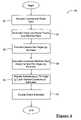
- FIG. 4is a flowchart illustrating an exemplary embodiment overview of a method for estimating unknown parameters for a vehicle object detection system
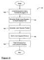
- FIG. 5is a more detailed flowchart illustrating an exemplary embodiment of a method for estimating a pan angle, which is preferably a step in the method shown in the flowchart of FIG. 4 ;
- FIG. 6is a more detailed flowchart illustrating an exemplary embodiment of a method for estimating an instantaneous tilt angle and vertical curvature, which are also preferably steps in the method shown in the flowchart of FIG. 4 .
- the present method for estimating unknown parameterscan be used with a number of different types of vehicle object detection systems, but is particularly well suited for use with forward looking, radar-cued vision systems (both monocular and stereo vision systems). Accordingly, the following description of the preferred embodiment is provided in the context of a forward looking, radar-cued vision system, even though the method of the present invention could be used with other types of object detection systems.
- a vehicle object detection system 10 of the forward looking, radar-cued monocular vision typethat generally includes a camera 12 , a radar sensor 14 and a processing unit 16 connected to the camera and the radar sensor.
- system 10could include one of any number of additional components and could be connected to other systems, devices, networks, etc., such as a warning indicator on a vehicle instrument panel, a vehicle braking system and a vehicle airbag system, to name but a few.
- Camera 12is mounted on a host vehicle 20 and is preferably pointed in a generally forward direction such that it captures a camera image of an area in front of the vehicle.
- camera 12is mounted within the passenger compartment, such as near the rearview mirror, but could alternatively be mounted at other suitable locations inside and outside of the passenger compartment.
- a “vision track”is broadly defined as a collection of data that is derived from a camera image and provides information on the position and/or other features of an object.
- each vision trackis provided in the form of pixel coordinates (p, q), which use a two-dimensional Cartesian coordinate system.
- a captured camera imageis periodically sent by camera 12 to processing unit 16 so that corresponding vision tracks can be obtained.
- Radar sensor 14is mounted on host vehicle 20 and pans back and forth across a predetermined angular range generally in front of the vehicle. Radar sensor 14 is commonly mounted outside of the passenger compartment, such as near the vehicle grille, but could be mounted at any other appropriate location inside or outside of the passenger compartment. Radar sensor 14 emits a generally narrow fan-shaped radar beam so that objects generally in front of the vehicle reflect the emitted radar back to the sensor. The radar reflections received by radar sensor 14 are sent to processing unit 16 so that corresponding radar tracks can be obtained.
- a “radar track”is broadly defined as a collection of data that is derived from radar reflections and provides information on the position and/or other features of an object. Preferably, each radar track is provided in the form of range and azimuth angle coordinates (R, ⁇ ), which use a two-dimensional Polar coordinate system.
- the vision and radar tracksuse different coordinate systems and therefore require a method for accurate translation.
- the image coordinates (p, q)represent a perspective transformation of three-dimensional world Cartesian coordinates into a two-dimensional Cartesian coordinate space, while the radar coordinates (R, ⁇ ) represent a two-dimensional subset of the three-dimensional world polar coordinates. Inverting the perspective transformations of the image and radar coordinates to recover the three-dimensional world coordinates, requires knowledge of extrinsic camera parameters and additional world information or constraints. For example, a point in the two-dimensional image maps to a line in the three-dimensional world coordinates.
- the additional world information or constraintswhich includes but is not limited to the vertical curvature of an upcoming road segment, is broadly represented here as the “road geometry.”
- One method for solving the correspondence between the pixel coordinates (p, q) of the vision track and the range and azimuth angle coordinates (R, ⁇ ) of the radar track,will be subsequently described.
- Processing unit 16receives the camera and radar data from camera 12 and radar sensor 14 , respectively, and executes a set of instructions for obtaining the vision and radar tracks and for estimating the unknown parameters pan angle, tilt angle and road geometry.
- unit 16includes a digital microprocessor and a set of firmware instructions stored on a digital memory device, however, other types of electronic processing devices, memory devices and software could be used as well.
- the firmwarecan include a number of additional instructions, such as those used for identifying, interpreting and/or locating objects. In that regard, the present method for estimating unknown parameters is only one sub-set of a larger set of firmware instructions likely to be executed by processing unit 16 .
- a warning signalcan be sent by unit 16 to the appropriate network, device, system, etc. so that a proper response can be determined.
- a warning signalcan be sent by unit 16 to the appropriate network, device, system, etc. so that a proper response can be determined.
- the pan angle ( ⁇ ) of camera 12is broadly defined as the horizontal angle between a camera boresight 30 and a radar boresight 32 .
- the various tilt angles of camera 12are shown in FIG. 3 and generally refer to the vertical misalignment between the camera boresight 30 and some other frame of reference.
- the nominal tilt angle ( ⁇ ) of the camerais generally defined as the vertical or “look down” angle between camera boresight 30 and a longitudinal axis 34 of the vehicle.
- the pitch angle ( ⁇ ) of the vehicleis generally defined as the vertical angle between the longitudinal axis 34 of the vehicle and a line 36 which is representative of the local slope under the vehicle; that is, line 36 is representative of the longitudinal axis of a planar ground patch under the vehicle.
- the pitch angle ( ⁇ ) of the vehicleis 0°.
- the instantaneous tilt angle ( ⁇ ) of the camerais broadly defined as the vertical angle between camera boresight 30 and line 36 , and is the superposition of the camera nominal tilt angle ( ⁇ ) and the vehicle pitch angle ( ⁇ ).
- the various tilt angles described abovecan be affected by a number of different events, including vehicle pitching which can occur when the vehicle drives over bumps or experiences substantial acceleration or deceleration.
- the landscape seen in the field-of-view of vehicle object detection system 10which is mostly of an upcoming road segment, may have an arbitrary geometry that can be approximated using a parameterized road geometry model.
- Prepresents a finite collection of parameters.
- Prepresents a finite collection of parameters.
- Prepresents a finite collection of parameters.
- Prepresents a finite collection of parameters.
- Suitable adjustment of the values of parameters Pallows for the approximation of arbitrary road scene geometries. The accuracy of such approximations depends on the complexity of the true road scene geometry, the complexity of the function h, and the number of parameters in P.
- processing unit 16selects certain sub-regions of the overall camera image that are most likely to contain the detected object. The larger the selected sub-regions, the more computational analysis that is required.
- method 50simplifies a number of non-linear equations in order to provide a best estimate for the unknown camera pan angle ( ⁇ ), camera instantaneous tilt angle ( ⁇ ) and road geometry, which in this particular embodiment is the vertical curvature (c) of the upcoming road segment.
- ⁇camera pan angle
- ⁇camera instantaneous tilt angle
- cvertical curvature
- processing unit 16receives camera and radar data from camera 12 and radar sensor 14 , respectively.
- the processing unitreviews the camera image and creates a vision track (pixel coordinates (p, q)) for each object that is detected from the image.
- a similar processis performed for the radar data such that a radar track (range and azimuth angle coordinates (R, ⁇ )) is created for each detected object.
- the objects detected in the camera dataare a sub-set of those detected in the radar data.
- each vision trackhas a corresponding radar track that relates to the same detected object and can be used to make a matched pair, step 54 .
- a “matched pair”is broadly defined as a pair of vision and radar tracks where each track generally relates to the location of the same object. Once one or more matched pairs have been obtained, a pan angle can be estimated.
- Step 56provides a pan angle ( ⁇ ) estimate that best fits the set of previously obtained matched pairs and does so independently of the instantaneous tilt angle ( ⁇ ) and vertical curvature (c).
- ⁇pan angle
- ⁇tilt angle
- cvertical curvature
- Coefficients A, B, C, D, E and Fshould be calculated, step 84 . Because the estimated pan angle is relatively insensitive to the value assumed for r, either a nominal value or the current estimate for long-term tilt angle can be used during the solution of the following equations. If AE ⁇ BD ⁇ 0, then the pan angle can be estimated using the following equation, step 86 .
- step 90filters all of the raw pan angle estimates to provide a single filtered, pan angle estimate ( ⁇ ).
- a low-pass filteris used to filter the various pan angle estimates.
- step 60a least squares problem is used which includes two unknown coefficients (instantaneous tilt angle ⁇ and vertical curvature c) and N equations (one equation for each matched pair).
- x c( cos ⁇ ⁇ ⁇ ⁇ ⁇ ⁇ cos ⁇ ⁇ ⁇ ) ⁇ x + ( sin ⁇ ⁇ ⁇ ⁇ cos ⁇ ⁇ ⁇ ) ⁇ y + sin ⁇ ⁇ ⁇ ⁇ ( h - 1 2 ⁇ cx 2 ) ( Eqn . ⁇ 9 )
- z c- ( cos ⁇ ⁇ ⁇ ⁇ ⁇ sin ⁇ ⁇ ⁇ ) ⁇ x - ( sin ⁇ ⁇ ⁇ ⁇ sin ⁇ ⁇ ⁇ ) ⁇ y + cos ⁇ ⁇ ⁇ ⁇ ( h - 1 2 ⁇ cx 2 ) ( Eqn . ⁇ 10 )
- step 102manipulates Eqn. 3 by substituting Eqns. 13 and 14 for x c and z c , respectively, which results in a single linear equation having two unknown coefficients ( ⁇ , c) for each matched pair.
- A- 1 2 ⁇ ( p - p 0 ) ⁇ x 2 ⁇ sin ⁇ ⁇ ⁇ 0 + f 2 ⁇ x 2 ⁇ cos ⁇ ⁇ ⁇ 0 ( Eqn . ⁇ 16 )
- B( p - p 0 ) ⁇ ( h ⁇ ⁇ cos ⁇ ⁇ ⁇ 0 - x ⁇ ⁇ sin ⁇ ⁇ ⁇ 0 ) + f ⁇ ( x ⁇ ⁇ cos ⁇ ⁇ ⁇ 0 + h ⁇ ⁇ sin ⁇ ⁇ ⁇ 0 ) ( Eqn .
- a minimum of two, but preferably more, matched pairsare needed to solve the least squares problem such that it has a unique solution, step 106 .
- matrix operationscan be used to solve for the least squares problem above so that the sum of the squares of the errors is minimized.
- the estimates obtained using the schemes abovewill be filtered, step 108 , to obtain final estimates.
- the tilt anglecould possibly be filtered using a model of the vehicle suspension's pitch dynamics or by some other technique known in the art.
- a last step 64entitled double checking, represents operations such as making sure there are enough matched pairs to make an estimate, checking intermediate values (e.g., before performing an arcsine operation), etc.
Landscapes
- Engineering & Computer Science (AREA)
- Radar, Positioning & Navigation (AREA)
- Remote Sensing (AREA)
- Physics & Mathematics (AREA)
- Computer Networks & Wireless Communication (AREA)
- General Physics & Mathematics (AREA)
- Electromagnetism (AREA)
- Traffic Control Systems (AREA)
- Radar Systems Or Details Thereof (AREA)
Abstract
Description
z=h(x,y,P), (Eqn. 1)
where P represents a finite collection of parameters. Suitable adjustment of the values of parameters P allows for the approximation of arbitrary road scene geometries. The accuracy of such approximations depends on the complexity of the true road scene geometry, the complexity of the function h, and the number of parameters in P.
[(q−q0)xcos τ−fy] cos ψ+[(q−q0)ycos τ−fx] sin ψ=−(q−q0)(z+h)sin τ (Eqn. 3)
[(p−p0)xcos τ+fxsin τ] cos ψ+[(p−p0)ycos τ+fysin τ] sin ψ=f(z+h)cos τ−(p−p0)(z+h)sin τ (Eqn. 4)
Acos ψ+Bsin ψ=C (Eqn. 5)
Dcos ψ+Esin ψ=F (Eqn. 6)
If AE−BD=0, it means the two equations are not linearly independent. Using a small angle approximation (cos ψ≈1) and if B≠0, then the pan angle can be estimated using the next equation,
In the case where AE−BD=0 or B=0 or (AF−CD)>(AE−BD) the pan angle estimate using this matched pair can be abandoned and control passes back to step80. This process continues until there are no more matched pairs to process, at which
sin τ=sin τ0+cos τ0(τ−τ0) (Eqn. 11)
cos τ=cos τ0−sin τ0(τ−τ0) (Eqn. 12)
Step100 substitutes the Taylor series equations and assumes that the pan angle (ψ)=0 (pan corrected radar tracks already take pan angle into account) to convert trigonometric Eqns. 9 and 10 into the following, simpler linear equations. So long as the tilt deviations remain small, this conversion can be accomplished without much loss of accuracy.
in Eqn. 13 and
in Eqn. 14 are assumed to be negligible and can be removed. With these terms removed,
where
A less accurate but considerably simplified alternative to the equations above, is:
Claims (12)
Priority Applications (2)
| Application Number | Priority Date | Filing Date | Title |
|---|---|---|---|
| US11/219,207US7706978B2 (en) | 2005-09-02 | 2005-09-02 | Method for estimating unknown parameters for a vehicle object detection system |
| EP06076622AEP1760491A3 (en) | 2005-09-02 | 2006-08-25 | Method for estimating unknown parameters for vehicle object detection system |
Applications Claiming Priority (1)
| Application Number | Priority Date | Filing Date | Title |
|---|---|---|---|
| US11/219,207US7706978B2 (en) | 2005-09-02 | 2005-09-02 | Method for estimating unknown parameters for a vehicle object detection system |
Publications (2)
| Publication Number | Publication Date |
|---|---|
| US20070055446A1 US20070055446A1 (en) | 2007-03-08 |
| US7706978B2true US7706978B2 (en) | 2010-04-27 |
Family
ID=37461466
Family Applications (1)
| Application Number | Title | Priority Date | Filing Date |
|---|---|---|---|
| US11/219,207Expired - Fee RelatedUS7706978B2 (en) | 2005-09-02 | 2005-09-02 | Method for estimating unknown parameters for a vehicle object detection system |
Country Status (2)
| Country | Link |
|---|---|
| US (1) | US7706978B2 (en) |
| EP (1) | EP1760491A3 (en) |
Cited By (35)
| Publication number | Priority date | Publication date | Assignee | Title |
|---|---|---|---|---|
| US20100001897A1 (en)* | 2007-01-25 | 2010-01-07 | Lyman Niall R | Radar Sensing System for Vehicle |
| US20100259614A1 (en)* | 2009-04-14 | 2010-10-14 | Honeywell International Inc. | Delay Compensated Feature Target System |
| US20110037640A1 (en)* | 2009-08-13 | 2011-02-17 | Tk Holdings Inc. | Object sensing system |
| US20110050482A1 (en)* | 2008-09-05 | 2011-03-03 | Toyota Jidosha Kabushiki Kaisha | Object detecting device |
| US20110163904A1 (en)* | 2008-10-08 | 2011-07-07 | Delphi Technologies, Inc. | Integrated radar-camera sensor |
| US20120008874A1 (en)* | 2009-04-07 | 2012-01-12 | Murata Machinery, Ltd. | Image processing apparatus, image processing method, image processing program, and storage medium |
| US20120188388A1 (en)* | 2011-01-20 | 2012-07-26 | Samsung Techwin Co., Ltd. | Method of controlling camera |
| US20130002470A1 (en)* | 2011-06-15 | 2013-01-03 | Honda Elesys Co., Ltd. | Obstacle detection apparatus and obstacle detection program |
| US20130103259A1 (en)* | 2011-10-20 | 2013-04-25 | GM Global Technology Operations LLC | Vehicle suspension system and method of using the same |
| US20130194127A1 (en)* | 2012-01-30 | 2013-08-01 | Hitachi Consumer Electronics Co., Ltd. | Vehicle collision risk prediction apparatus |
| EP2660625A1 (en)* | 2012-04-30 | 2013-11-06 | Traficon International N.V. | A method for monitoring a traffic stream and a traffic monitoring device |
| US20140097295A1 (en)* | 2012-10-05 | 2014-04-10 | Dassault Aviation | Nose section for a flying machine and associated flying machine |
| US8825391B1 (en)* | 2011-08-04 | 2014-09-02 | Google Inc. | Building elevation maps from laser data |
| US8849554B2 (en) | 2010-11-15 | 2014-09-30 | Image Sensing Systems, Inc. | Hybrid traffic system and associated method |
| US9063230B2 (en) | 2008-10-08 | 2015-06-23 | Delphi Technologies, Inc. | Radar sensor module |
| US9293812B2 (en) | 2013-11-06 | 2016-03-22 | Delphi Technologies, Inc. | Radar antenna assembly |
| US20160163108A1 (en)* | 2014-12-08 | 2016-06-09 | Hyundai Motor Company | Augmented reality hud display method and device for vehicle |
| US9472097B2 (en) | 2010-11-15 | 2016-10-18 | Image Sensing Systems, Inc. | Roadway sensing systems |
| US20180025234A1 (en)* | 2016-07-20 | 2018-01-25 | Ford Global Technologies, Llc | Rear camera lane detection |
| US20180086265A1 (en)* | 2016-09-26 | 2018-03-29 | Volvo Car Corporation | Method, system and vehicle for use of an object displaying device in a vehicle |
| US9948409B2 (en)* | 2016-09-20 | 2018-04-17 | Infineon Technologies Ag | Phase and amplitude signal sensing circuit for radio frequency (RF) transmitters |
| US20190120934A1 (en)* | 2017-10-19 | 2019-04-25 | GM Global Technology Operations LLC | Three-dimensional alignment of radar and camera sensors |
| US10295663B2 (en)* | 2015-07-10 | 2019-05-21 | Renesas Electronics Corporation | Semiconductor device, control system and observation method |
| US10369994B2 (en) | 2016-07-20 | 2019-08-06 | Ford Global Technologies, Llc | Rear camera stub detection |
| US20200018822A1 (en)* | 2018-07-10 | 2020-01-16 | Ford Motor Company | Method and system for performing a vehicle height-radar alignment check to align a radar device provided in a vehicle |
| US10728461B1 (en)* | 2019-01-31 | 2020-07-28 | StradVision, Inc. | Method for correcting misalignment of camera by selectively using information generated by itself and information generated by other entities and device using the same |
| US10877148B2 (en) | 2017-09-07 | 2020-12-29 | Magna Electronics Inc. | Vehicle radar sensing system with enhanced angle resolution using synthesized aperture |
| US10890648B2 (en)* | 2014-10-24 | 2021-01-12 | Texas Instruments Incorporated | Method and apparatus for generating alignment matrix for camera-radar system |
| US10962641B2 (en) | 2017-09-07 | 2021-03-30 | Magna Electronics Inc. | Vehicle radar sensing system with enhanced accuracy using interferometry techniques |
| US10962638B2 (en) | 2017-09-07 | 2021-03-30 | Magna Electronics Inc. | Vehicle radar sensing system with surface modeling |
| US11087148B2 (en)* | 2010-09-21 | 2021-08-10 | Mobileye Vision Technologies Ltd. | Barrier and guardrail detection using a single camera |
| US11150342B2 (en) | 2017-09-07 | 2021-10-19 | Magna Electronics Inc. | Vehicle radar sensing system with surface segmentation using interferometric statistical analysis |
| US20220101650A1 (en)* | 2019-02-01 | 2022-03-31 | Samsung Electronics Co., Ltd. | Method for recognizing object by using millimeter wave and electronic device supporting same method |
| US11360191B2 (en)* | 2019-12-27 | 2022-06-14 | Woven Planet North America, Inc. | Adaptive tilting radars for effective vehicle controls |
| US11474234B2 (en)* | 2018-03-20 | 2022-10-18 | Hl Klemove Corp. | Device and method for estimating distance based on object detection |
Families Citing this family (54)
| Publication number | Priority date | Publication date | Assignee | Title |
|---|---|---|---|---|
| DE102009013667A1 (en)* | 2009-03-24 | 2010-09-30 | Jenoptik Robot Gmbh | A method of producing a known fixed spatial relationship between a laser scanner and a digital camera for traffic surveillance |
| EP2347940A1 (en)* | 2010-01-25 | 2011-07-27 | Autoliv Development AB | An object collision warning system and method for a motor vehicle |
| US9135830B2 (en)* | 2010-02-18 | 2015-09-15 | Xsight Systems Ltd. | Airport travel surface edge lighting and foreign object detection system and method |
| DE102011056948A1 (en)* | 2011-12-22 | 2013-06-27 | Jenoptik Robot Gmbh | Method for calibrating a camera to a position sensor |
| WO2014160027A1 (en)* | 2013-03-13 | 2014-10-02 | Image Sensing Systems, Inc. | Roadway sensing systems |
| EP2972474A4 (en) | 2013-03-15 | 2016-10-26 | Kirill Mostov | MULTI-SENSOR MONITORING SYSTEM FOR MONITORING SPACE AND DETECTING OBJECTS |
| US9582886B2 (en)* | 2013-07-08 | 2017-02-28 | Honda Motor Co., Ltd. | Object recognition device |
| CN104349036B (en)* | 2013-07-29 | 2019-03-29 | 联想(北京)有限公司 | A kind of method and electronic equipment of information processing |
| SE537621C2 (en)* | 2013-09-10 | 2015-08-11 | Scania Cv Ab | Detection of objects using a 3D camera and a radar |
| EP2853916A1 (en)* | 2013-09-25 | 2015-04-01 | Application Solutions (Electronics and Vision) Limited | A method and apparatus for providing a 3-dimensional ground surface model used for mapping |
| JP6317657B2 (en) | 2013-11-06 | 2018-04-25 | デルファイ・テクノロジーズ・インコーポレーテッド | Radar sensor module |
| JP6428270B2 (en) | 2014-02-10 | 2018-11-28 | 株式会社デンソー | Axis deviation detector |
| WO2015119298A1 (en)* | 2014-02-10 | 2015-08-13 | 株式会社デンソー | Axis deviation detection device for beam sensor |
| EP3108264A2 (en)* | 2014-02-20 | 2016-12-28 | Mobileye Vision Technologies Ltd. | Advanced driver assistance system based on radar-cued visual imaging |
| KR102214332B1 (en)* | 2014-04-30 | 2021-02-10 | 주식회사 만도 | System for making a driver operate a car easily method for determining abnormality vertical angle of radar sensor at system for making a driver operate a car easily |
| CN111969336B (en) | 2014-05-06 | 2023-03-28 | 安波福技术有限公司 | Radar antenna assembly |
| JP6396714B2 (en)* | 2014-08-06 | 2018-09-26 | 株式会社デンソー | Object recognition device |
| JP6265149B2 (en)* | 2014-08-27 | 2018-01-24 | 株式会社デンソー | Detection device |
| US9671493B1 (en)* | 2014-09-19 | 2017-06-06 | Hrl Laboratories, Llc | Automated scheduling of radar-cued camera system for optimizing visual inspection (detection) of radar targets |
| JP6265095B2 (en)* | 2014-09-24 | 2018-01-24 | 株式会社デンソー | Object detection device |
| US11505292B2 (en)* | 2014-12-31 | 2022-11-22 | FLIR Belgium BVBA | Perimeter ranging sensor systems and methods |
| US10678261B2 (en) | 2015-02-06 | 2020-06-09 | Aptiv Technologies Limited | Method and apparatus for controlling an autonomous vehicle |
| KR102256676B1 (en)* | 2015-02-06 | 2021-05-26 | 삼성전자주식회사 | Multi-purpose device including mobile terminal and sensing device using radio-wave based sensor |
| WO2016126317A1 (en) | 2015-02-06 | 2016-08-11 | Delphi Technologies, Inc. | Method of automatically controlling an autonomous vehicle based on electronic messages from roadside infrastructure of other vehicles |
| WO2016126316A1 (en)* | 2015-02-06 | 2016-08-11 | Delphi Technologies, Inc. | Autonomous guidance system |
| JP6523050B2 (en)* | 2015-06-02 | 2019-05-29 | 日立建機株式会社 | Mining work machine |
| US10235817B2 (en)* | 2015-09-01 | 2019-03-19 | Ford Global Technologies, Llc | Motion compensation for on-board vehicle sensors |
| US10565468B2 (en)* | 2016-01-19 | 2020-02-18 | Aptiv Technologies Limited | Object tracking system with radar/vision fusion for automated vehicles |
| JP6679372B2 (en)* | 2016-03-28 | 2020-04-15 | セコム株式会社 | Object detection device |
| US10304335B2 (en)* | 2016-04-12 | 2019-05-28 | Ford Global Technologies, Llc | Detecting available parking spaces |
| US9888357B2 (en)* | 2016-05-30 | 2018-02-06 | Qatar University Qstp-B | Methods and systems for identifying the user of a smartphone inside a moving vehicle and automatic detection and calculation of the time and location when and where a vehicle has been parked |
| US11092446B2 (en) | 2016-06-14 | 2021-08-17 | Motional Ad Llc | Route planning for an autonomous vehicle |
| US10309792B2 (en) | 2016-06-14 | 2019-06-04 | nuTonomy Inc. | Route planning for an autonomous vehicle |
| US10126136B2 (en) | 2016-06-14 | 2018-11-13 | nuTonomy Inc. | Route planning for an autonomous vehicle |
| US10681513B2 (en) | 2016-10-20 | 2020-06-09 | nuTonomy Inc. | Identifying a stopping place for an autonomous vehicle |
| US10857994B2 (en) | 2016-10-20 | 2020-12-08 | Motional Ad Llc | Identifying a stopping place for an autonomous vehicle |
| US10473470B2 (en) | 2016-10-20 | 2019-11-12 | nuTonomy Inc. | Identifying a stopping place for an autonomous vehicle |
| US10331129B2 (en) | 2016-10-20 | 2019-06-25 | nuTonomy Inc. | Identifying a stopping place for an autonomous vehicle |
| US10025311B2 (en) | 2016-10-28 | 2018-07-17 | Delphi Technologies, Inc. | Automated vehicle sensor control system |
| US10552691B2 (en)* | 2017-04-25 | 2020-02-04 | TuSimple | System and method for vehicle position and velocity estimation based on camera and lidar data |
| US12205473B2 (en) | 2017-06-16 | 2025-01-21 | FLIR Belgium BVBA | Collision avoidance systems and methods |
| US12084155B2 (en) | 2017-06-16 | 2024-09-10 | FLIR Belgium BVBA | Assisted docking graphical user interface systems and methods |
| JP6598885B2 (en)* | 2018-01-05 | 2019-10-30 | 三菱電機株式会社 | Object recognition apparatus and object recognition method |
| EP3575829B1 (en)* | 2018-05-30 | 2020-11-18 | Axis AB | A method of determining a transformation matrix |
| US10935652B2 (en)* | 2018-06-26 | 2021-03-02 | GM Global Technology Operations LLC | Systems and methods for using road understanding to constrain radar tracks |
| JP2022036339A (en)* | 2018-10-12 | 2022-03-08 | ソニーセミコンダクタソリューションズ株式会社 | Sensor fusion system, synchronization control device, and synchronization control method |
| US12117832B2 (en) | 2018-10-31 | 2024-10-15 | FLIR Belgium BVBA | Dynamic proximity alert systems and methods |
| JP7540338B2 (en)* | 2018-11-30 | 2024-08-27 | ソニーグループ株式会社 | Information processing device, information processing system, and information processing method |
| KR20200102013A (en)* | 2019-02-01 | 2020-08-31 | 주식회사 만도 | Parking space notification device and method thereof |
| EP3757611A1 (en)* | 2019-06-27 | 2020-12-30 | Aptiv Technologies Limited | Vertical road profile estimation |
| JP2024038527A (en)* | 2021-01-12 | 2024-03-21 | ソニーセミコンダクタソリューションズ株式会社 | Signal processing device, signal processing method, and signal processing system |
| CN114266859B (en)* | 2021-12-02 | 2022-09-06 | 国汽智控(北京)科技有限公司 | Data processing method, device, equipment and storage medium |
| CN120418188A (en)* | 2022-12-28 | 2025-08-01 | 住友重机械工业株式会社 | Perimeter monitoring system for work machine |
| US12301986B2 (en)* | 2022-12-28 | 2025-05-13 | Motorola Solutions, Inc. | Tamper reduction for quick deploy camera system |
Citations (35)
| Publication number | Priority date | Publication date | Assignee | Title |
|---|---|---|---|---|
| US3946382A (en)* | 1970-01-28 | 1976-03-23 | The United States Of America As Represented By The Secretary Of The Navy | Search radar adaptive video processor |
| US4068233A (en)* | 1976-08-13 | 1978-01-10 | Raytheon Company | Radar system having interference rejection |
| US4128838A (en)* | 1976-02-16 | 1978-12-05 | Hollandse Signaalapparaten B.V. | Digital scan converter |
| US4274095A (en)* | 1979-03-21 | 1981-06-16 | The United States Of America As Represented By The Secretary Of The Navy | Radar video converter |
| US4336539A (en)* | 1978-10-05 | 1982-06-22 | Hendrickson Alvin E | Navigational aid device |
| US4443797A (en)* | 1980-01-22 | 1984-04-17 | Decca Limited | Radar display apparatus |
| US4516125A (en)* | 1982-09-20 | 1985-05-07 | General Signal Corporation | Method and apparatus for monitoring vehicle ground movement in the vicinity of an airport |
| US4845501A (en)* | 1986-01-27 | 1989-07-04 | Raytheon Company | Radar video scan converter |
| US5418535A (en)* | 1993-10-25 | 1995-05-23 | Cardion, Inc. | Mixed radar/graphics indicator |
| US5519401A (en)* | 1993-11-01 | 1996-05-21 | Loral Corporation | Programmed radar coordinate scan conversion |
| US5596327A (en)* | 1995-11-06 | 1997-01-21 | The United States Of America As Represented By The Secretary Of The Navy | Radar encoder |
| US5867121A (en)* | 1997-04-17 | 1999-02-02 | Litton Systems, Inc. | Radar scan converter system |
| US6087982A (en)* | 1999-05-27 | 2000-07-11 | Chung-Shan Institute Of Science And Technology | Radar scan converter and method of mixing image |
| US20020060640A1 (en)* | 1994-06-01 | 2002-05-23 | American Traffic Systems, Inc. | Doppler-shift radar transceiver for traffic monitoring system |
| US20020072869A1 (en) | 1999-12-24 | 2002-06-13 | Christoph Stiller | Method of calibrating a sensor system |
| US20020167589A1 (en)* | 1993-02-26 | 2002-11-14 | Kenneth Schofield | Rearview vision system for vehicle including panoramic view |
| US20030011509A1 (en)* | 2000-12-20 | 2003-01-16 | Kanako Honda | Method for detecting stationary object on road |
| US20030088361A1 (en)* | 2001-11-02 | 2003-05-08 | Fuji Jukogyo Kabushiki Kaisha | Monitor system of vehicle outside and the method thereof |
| US6580385B1 (en)* | 1999-05-26 | 2003-06-17 | Robert Bosch Gmbh | Object detection system |
| US20030187578A1 (en)* | 2002-02-01 | 2003-10-02 | Hikaru Nishira | Method and system for vehicle operator assistance improvement |
| US20030201929A1 (en)* | 2002-04-24 | 2003-10-30 | Lutter Robert Pierce Pierce | Multi-sensor system |
| US20040012516A1 (en) | 2002-07-16 | 2004-01-22 | Schiffmann Jan K. | Tracking system and method employing multiple overlapping sensors |
| US20040054473A1 (en)* | 2002-09-17 | 2004-03-18 | Nissan Motor Co., Ltd. | Vehicle tracking system |
| US20040151345A1 (en)* | 2001-04-04 | 2004-08-05 | Morcom Christopher John | Image analysis apparatus |
| US20040183712A1 (en)* | 2002-08-28 | 2004-09-23 | Levitan Arthur C. | Methods and apparatus for detecting threats in different areas |
| US20040246471A1 (en)* | 2003-04-04 | 2004-12-09 | Yoshio Matsuura | Method of adjusting axial direction of monitoring apparatus |
| US20050004762A1 (en)* | 2003-07-01 | 2005-01-06 | Nissan Motor Co., Ltd. | Obstacle detection apparatus and method for automotive vehicle |
| US20050099433A1 (en)* | 2003-11-11 | 2005-05-12 | Supersonic Aerospace International, Llc | System and method for mounting sensors and cleaning sensor apertures for out-the-window displays |
| US6900754B2 (en)* | 2001-03-15 | 2005-05-31 | Fujitsu Tem Limited | Signal processing method for use with scanning radar |
| US20050146458A1 (en)* | 2004-01-07 | 2005-07-07 | Carmichael Steve D. | Vehicular electronics interface module and related methods |
| US20050187713A1 (en)* | 2001-08-23 | 2005-08-25 | Nissan Motor Co., Ltd. | Driving assist system |
| US20050219530A1 (en)* | 2004-04-02 | 2005-10-06 | Omron Corporation | Method of adjusting monitor axis |
| US20050228588A1 (en)* | 2002-04-23 | 2005-10-13 | Goetz Braeuchle | Lateral guidance assistance for motor vehicles |
| US7263209B2 (en)* | 2003-06-13 | 2007-08-28 | Sarnoff Corporation | Vehicular vision system |
| US7522747B2 (en)* | 2004-03-26 | 2009-04-21 | Omron Corporation | Vehicle detection apparatus and method |
- 2005
- 2005-09-02USUS11/219,207patent/US7706978B2/ennot_activeExpired - Fee Related
- 2006
- 2006-08-25EPEP06076622Apatent/EP1760491A3/ennot_activeWithdrawn
Patent Citations (37)
| Publication number | Priority date | Publication date | Assignee | Title |
|---|---|---|---|---|
| US3946382A (en)* | 1970-01-28 | 1976-03-23 | The United States Of America As Represented By The Secretary Of The Navy | Search radar adaptive video processor |
| US4128838A (en)* | 1976-02-16 | 1978-12-05 | Hollandse Signaalapparaten B.V. | Digital scan converter |
| US4068233A (en)* | 1976-08-13 | 1978-01-10 | Raytheon Company | Radar system having interference rejection |
| US4336539A (en)* | 1978-10-05 | 1982-06-22 | Hendrickson Alvin E | Navigational aid device |
| US4274095A (en)* | 1979-03-21 | 1981-06-16 | The United States Of America As Represented By The Secretary Of The Navy | Radar video converter |
| US4443797A (en)* | 1980-01-22 | 1984-04-17 | Decca Limited | Radar display apparatus |
| US4516125A (en)* | 1982-09-20 | 1985-05-07 | General Signal Corporation | Method and apparatus for monitoring vehicle ground movement in the vicinity of an airport |
| US4845501A (en)* | 1986-01-27 | 1989-07-04 | Raytheon Company | Radar video scan converter |
| US20020167589A1 (en)* | 1993-02-26 | 2002-11-14 | Kenneth Schofield | Rearview vision system for vehicle including panoramic view |
| US5418535A (en)* | 1993-10-25 | 1995-05-23 | Cardion, Inc. | Mixed radar/graphics indicator |
| US5519401A (en)* | 1993-11-01 | 1996-05-21 | Loral Corporation | Programmed radar coordinate scan conversion |
| US20020060640A1 (en)* | 1994-06-01 | 2002-05-23 | American Traffic Systems, Inc. | Doppler-shift radar transceiver for traffic monitoring system |
| US5596327A (en)* | 1995-11-06 | 1997-01-21 | The United States Of America As Represented By The Secretary Of The Navy | Radar encoder |
| US5867121A (en)* | 1997-04-17 | 1999-02-02 | Litton Systems, Inc. | Radar scan converter system |
| US6580385B1 (en)* | 1999-05-26 | 2003-06-17 | Robert Bosch Gmbh | Object detection system |
| US6087982A (en)* | 1999-05-27 | 2000-07-11 | Chung-Shan Institute Of Science And Technology | Radar scan converter and method of mixing image |
| US20020072869A1 (en) | 1999-12-24 | 2002-06-13 | Christoph Stiller | Method of calibrating a sensor system |
| US20030011509A1 (en)* | 2000-12-20 | 2003-01-16 | Kanako Honda | Method for detecting stationary object on road |
| US6900754B2 (en)* | 2001-03-15 | 2005-05-31 | Fujitsu Tem Limited | Signal processing method for use with scanning radar |
| US20040151345A1 (en)* | 2001-04-04 | 2004-08-05 | Morcom Christopher John | Image analysis apparatus |
| US20050187713A1 (en)* | 2001-08-23 | 2005-08-25 | Nissan Motor Co., Ltd. | Driving assist system |
| US20030088361A1 (en)* | 2001-11-02 | 2003-05-08 | Fuji Jukogyo Kabushiki Kaisha | Monitor system of vehicle outside and the method thereof |
| US20030187578A1 (en)* | 2002-02-01 | 2003-10-02 | Hikaru Nishira | Method and system for vehicle operator assistance improvement |
| US20050228588A1 (en)* | 2002-04-23 | 2005-10-13 | Goetz Braeuchle | Lateral guidance assistance for motor vehicles |
| US20030201929A1 (en)* | 2002-04-24 | 2003-10-30 | Lutter Robert Pierce Pierce | Multi-sensor system |
| US6771208B2 (en)* | 2002-04-24 | 2004-08-03 | Medius, Inc. | Multi-sensor system |
| US6873251B2 (en)* | 2002-07-16 | 2005-03-29 | Delphi Technologies, Inc. | Tracking system and method employing multiple overlapping sensors |
| US20040012516A1 (en) | 2002-07-16 | 2004-01-22 | Schiffmann Jan K. | Tracking system and method employing multiple overlapping sensors |
| US20040183712A1 (en)* | 2002-08-28 | 2004-09-23 | Levitan Arthur C. | Methods and apparatus for detecting threats in different areas |
| US20040054473A1 (en)* | 2002-09-17 | 2004-03-18 | Nissan Motor Co., Ltd. | Vehicle tracking system |
| US20040246471A1 (en)* | 2003-04-04 | 2004-12-09 | Yoshio Matsuura | Method of adjusting axial direction of monitoring apparatus |
| US7263209B2 (en)* | 2003-06-13 | 2007-08-28 | Sarnoff Corporation | Vehicular vision system |
| US20050004762A1 (en)* | 2003-07-01 | 2005-01-06 | Nissan Motor Co., Ltd. | Obstacle detection apparatus and method for automotive vehicle |
| US20050099433A1 (en)* | 2003-11-11 | 2005-05-12 | Supersonic Aerospace International, Llc | System and method for mounting sensors and cleaning sensor apertures for out-the-window displays |
| US20050146458A1 (en)* | 2004-01-07 | 2005-07-07 | Carmichael Steve D. | Vehicular electronics interface module and related methods |
| US7522747B2 (en)* | 2004-03-26 | 2009-04-21 | Omron Corporation | Vehicle detection apparatus and method |
| US20050219530A1 (en)* | 2004-04-02 | 2005-10-06 | Omron Corporation | Method of adjusting monitor axis |
Cited By (78)
| Publication number | Priority date | Publication date | Assignee | Title |
|---|---|---|---|---|
| US20210109212A1 (en)* | 2007-01-25 | 2021-04-15 | Magna Electronics Inc. | Vehicular forward-sensing system |
| US9244165B1 (en) | 2007-01-25 | 2016-01-26 | Magna Electronics Inc. | Forward facing sensing system for vehicle |
| US10107905B2 (en) | 2007-01-25 | 2018-10-23 | Magna Electronics Inc. | Forward facing sensing system for vehicle |
| US20190056493A1 (en)* | 2007-01-25 | 2019-02-21 | Magna Electronics Inc. | Forward sensing system for vehicle |
| US20100001897A1 (en)* | 2007-01-25 | 2010-01-07 | Lyman Niall R | Radar Sensing System for Vehicle |
| US9507021B2 (en)* | 2007-01-25 | 2016-11-29 | Magna Electronics Inc. | Forward facing sensing system for vehicle |
| US8013780B2 (en)* | 2007-01-25 | 2011-09-06 | Magna Electronics Inc. | Radar sensing system for vehicle |
| US20110285576A1 (en)* | 2007-01-25 | 2011-11-24 | Lynam Niall R | Forward facing sensing system for a vehicle |
| US20160252612A1 (en)* | 2007-01-25 | 2016-09-01 | Magna Electronics Inc. | Forward facing sensing system for vehicle |
| US8217830B2 (en)* | 2007-01-25 | 2012-07-10 | Magna Electronics Inc. | Forward facing sensing system for a vehicle |
| US10670713B2 (en)* | 2007-01-25 | 2020-06-02 | Magna Electronics Inc. | Forward sensing system for vehicle |
| US8294608B1 (en)* | 2007-01-25 | 2012-10-23 | Magna Electronics, Inc. | Forward facing sensing system for vehicle |
| US9335411B1 (en)* | 2007-01-25 | 2016-05-10 | Magna Electronics Inc. | Forward facing sensing system for vehicle |
| US20130044021A1 (en)* | 2007-01-25 | 2013-02-21 | Magna Electronics Inc. | Forward facing sensing system for vehicle |
| US11815594B2 (en)* | 2007-01-25 | 2023-11-14 | Magna Electronics Inc. | Vehicular forward-sensing system |
| US10877147B2 (en)* | 2007-01-25 | 2020-12-29 | Magna Electronics Inc. | Forward sensing system for vehicle |
| US20230110888A1 (en)* | 2007-01-25 | 2023-04-13 | Magna Electronics Inc. | Vehicular forward-sensing system |
| US8614640B2 (en)* | 2007-01-25 | 2013-12-24 | Magna Electronics Inc. | Forward facing sensing system for vehicle |
| US9140789B2 (en)* | 2007-01-25 | 2015-09-22 | Magna Electronics Inc. | Forward facing sensing system for vehicle |
| US20140104095A1 (en)* | 2007-01-25 | 2014-04-17 | Magna Electronics Inc. | Forward facing sensing system for vehicle |
| US11506782B2 (en)* | 2007-01-25 | 2022-11-22 | Magna Electronics Inc. | Vehicular forward-sensing system |
| US20110050482A1 (en)* | 2008-09-05 | 2011-03-03 | Toyota Jidosha Kabushiki Kaisha | Object detecting device |
| US8466827B2 (en)* | 2008-09-05 | 2013-06-18 | Toyota Jidosha Kabushiki Kaisha | Object detecting device |
| US8604968B2 (en) | 2008-10-08 | 2013-12-10 | Delphi Technologies, Inc. | Integrated radar-camera sensor |
| US20110163904A1 (en)* | 2008-10-08 | 2011-07-07 | Delphi Technologies, Inc. | Integrated radar-camera sensor |
| US9063230B2 (en) | 2008-10-08 | 2015-06-23 | Delphi Technologies, Inc. | Radar sensor module |
| US20120008874A1 (en)* | 2009-04-07 | 2012-01-12 | Murata Machinery, Ltd. | Image processing apparatus, image processing method, image processing program, and storage medium |
| US8682080B2 (en)* | 2009-04-07 | 2014-03-25 | Murata Machinery, Ltd. | Image processing apparatus, image processing method, image processing program, and storage medium |
| US20100259614A1 (en)* | 2009-04-14 | 2010-10-14 | Honeywell International Inc. | Delay Compensated Feature Target System |
| US20110037640A1 (en)* | 2009-08-13 | 2011-02-17 | Tk Holdings Inc. | Object sensing system |
| US7978122B2 (en)* | 2009-08-13 | 2011-07-12 | Tk Holdings Inc. | Object sensing system |
| US11087148B2 (en)* | 2010-09-21 | 2021-08-10 | Mobileye Vision Technologies Ltd. | Barrier and guardrail detection using a single camera |
| US11080995B2 (en) | 2010-11-15 | 2021-08-03 | Image Sensing Systems, Inc. | Roadway sensing systems |
| US10055979B2 (en) | 2010-11-15 | 2018-08-21 | Image Sensing Systems, Inc. | Roadway sensing systems |
| US8849554B2 (en) | 2010-11-15 | 2014-09-30 | Image Sensing Systems, Inc. | Hybrid traffic system and associated method |
| US9472097B2 (en) | 2010-11-15 | 2016-10-18 | Image Sensing Systems, Inc. | Roadway sensing systems |
| US8854461B2 (en)* | 2011-01-20 | 2014-10-07 | Samsung Techwin Co., Ltd. | Method of controlling camera |
| US20120188388A1 (en)* | 2011-01-20 | 2012-07-26 | Samsung Techwin Co., Ltd. | Method of controlling camera |
| US20130002470A1 (en)* | 2011-06-15 | 2013-01-03 | Honda Elesys Co., Ltd. | Obstacle detection apparatus and obstacle detection program |
| US9097801B2 (en)* | 2011-06-15 | 2015-08-04 | Honda Elesys Co., Ltd. | Obstacle detection apparatus and obstacle detection program |
| US9709679B1 (en) | 2011-08-04 | 2017-07-18 | Waymo Llc | Building elevation maps from laser data |
| US10185324B1 (en) | 2011-08-04 | 2019-01-22 | Waymo Llc | Building elevation maps from laser data |
| US8825391B1 (en)* | 2011-08-04 | 2014-09-02 | Google Inc. | Building elevation maps from laser data |
| US9533539B2 (en)* | 2011-10-20 | 2017-01-03 | GM Global Technology Operations LLC | Vehicle suspension system and method of using the same |
| US20130103259A1 (en)* | 2011-10-20 | 2013-04-25 | GM Global Technology Operations LLC | Vehicle suspension system and method of using the same |
| US20130194127A1 (en)* | 2012-01-30 | 2013-08-01 | Hitachi Consumer Electronics Co., Ltd. | Vehicle collision risk prediction apparatus |
| US9197866B2 (en) | 2012-04-30 | 2015-11-24 | Flir Systems, Inc. | Method for monitoring a traffic stream and a traffic monitoring device |
| EP2660624A1 (en)* | 2012-04-30 | 2013-11-06 | Traficon International N.V. | A traffic monitoring device and a method for monitoring a traffic stream. |
| EP2660625A1 (en)* | 2012-04-30 | 2013-11-06 | Traficon International N.V. | A method for monitoring a traffic stream and a traffic monitoring device |
| US10286994B2 (en)* | 2012-10-05 | 2019-05-14 | Dassault Aviation | Nose section for a flying machine and associated flying machine |
| US20140097295A1 (en)* | 2012-10-05 | 2014-04-10 | Dassault Aviation | Nose section for a flying machine and associated flying machine |
| US9293812B2 (en) | 2013-11-06 | 2016-03-22 | Delphi Technologies, Inc. | Radar antenna assembly |
| US10890648B2 (en)* | 2014-10-24 | 2021-01-12 | Texas Instruments Incorporated | Method and apparatus for generating alignment matrix for camera-radar system |
| US9690104B2 (en)* | 2014-12-08 | 2017-06-27 | Hyundai Motor Company | Augmented reality HUD display method and device for vehicle |
| US20160163108A1 (en)* | 2014-12-08 | 2016-06-09 | Hyundai Motor Company | Augmented reality hud display method and device for vehicle |
| US10295663B2 (en)* | 2015-07-10 | 2019-05-21 | Renesas Electronics Corporation | Semiconductor device, control system and observation method |
| US10369994B2 (en) | 2016-07-20 | 2019-08-06 | Ford Global Technologies, Llc | Rear camera stub detection |
| US10762358B2 (en)* | 2016-07-20 | 2020-09-01 | Ford Global Technologies, Llc | Rear camera lane detection |
| US20180025234A1 (en)* | 2016-07-20 | 2018-01-25 | Ford Global Technologies, Llc | Rear camera lane detection |
| US10305610B2 (en) | 2016-09-20 | 2019-05-28 | Infineon Technologies Ag | Phase and amplitude signal sensing circuit for radio frequency (RF) transmitters |
| US9948409B2 (en)* | 2016-09-20 | 2018-04-17 | Infineon Technologies Ag | Phase and amplitude signal sensing circuit for radio frequency (RF) transmitters |
| US11279371B2 (en)* | 2016-09-26 | 2022-03-22 | Volvo Car Corporation | Method, system and vehicle for use of an object displaying device in a vehicle |
| US20180086265A1 (en)* | 2016-09-26 | 2018-03-29 | Volvo Car Corporation | Method, system and vehicle for use of an object displaying device in a vehicle |
| US10962641B2 (en) | 2017-09-07 | 2021-03-30 | Magna Electronics Inc. | Vehicle radar sensing system with enhanced accuracy using interferometry techniques |
| US11703587B2 (en) | 2017-09-07 | 2023-07-18 | Magna Electronics Inc. | Vehicle radar sensing system with enhanced angle resolution |
| US10962638B2 (en) | 2017-09-07 | 2021-03-30 | Magna Electronics Inc. | Vehicle radar sensing system with surface modeling |
| US11150342B2 (en) | 2017-09-07 | 2021-10-19 | Magna Electronics Inc. | Vehicle radar sensing system with surface segmentation using interferometric statistical analysis |
| US10877148B2 (en) | 2017-09-07 | 2020-12-29 | Magna Electronics Inc. | Vehicle radar sensing system with enhanced angle resolution using synthesized aperture |
| US12025696B2 (en) | 2017-09-07 | 2024-07-02 | Magna Electronics Inc. | Vehicle radar sensing system with enhanced angle resolution |
| US11867802B2 (en) | 2017-09-07 | 2024-01-09 | Magna Electronics Inc. | Vehicle radar sensing system |
| US20190120934A1 (en)* | 2017-10-19 | 2019-04-25 | GM Global Technology Operations LLC | Three-dimensional alignment of radar and camera sensors |
| US11474234B2 (en)* | 2018-03-20 | 2022-10-18 | Hl Klemove Corp. | Device and method for estimating distance based on object detection |
| US20200018822A1 (en)* | 2018-07-10 | 2020-01-16 | Ford Motor Company | Method and system for performing a vehicle height-radar alignment check to align a radar device provided in a vehicle |
| US11029390B2 (en)* | 2018-07-10 | 2021-06-08 | Ford Motor Company | Method and system for performing a vehicle height-radar alignment check to align a radar device provided in a vehicle |
| US10728461B1 (en)* | 2019-01-31 | 2020-07-28 | StradVision, Inc. | Method for correcting misalignment of camera by selectively using information generated by itself and information generated by other entities and device using the same |
| US20220101650A1 (en)* | 2019-02-01 | 2022-03-31 | Samsung Electronics Co., Ltd. | Method for recognizing object by using millimeter wave and electronic device supporting same method |
| US12123768B2 (en)* | 2019-02-01 | 2024-10-22 | Samsung Electronics Co., Ltd. | Method for recognizing object by using millimeter wave and electronic device supporting same method |
| US11360191B2 (en)* | 2019-12-27 | 2022-06-14 | Woven Planet North America, Inc. | Adaptive tilting radars for effective vehicle controls |
Also Published As
| Publication number | Publication date |
|---|---|
| US20070055446A1 (en) | 2007-03-08 |
| EP1760491A2 (en) | 2007-03-07 |
| EP1760491A3 (en) | 2009-12-09 |
Similar Documents
| Publication | Publication Date | Title |
|---|---|---|
| US7706978B2 (en) | Method for estimating unknown parameters for a vehicle object detection system | |
| US9576207B2 (en) | Method for angle calibration of the position of a video camera on board an automotive vehicle | |
| EP3193306B1 (en) | A method and a device for estimating an orientation of a camera relative to a road surface | |
| US6005492A (en) | Road lane recognizing apparatus | |
| US8824741B2 (en) | Method for estimating the roll angle in a travelling vehicle | |
| US10984555B2 (en) | Object detection device and vehicle | |
| US20040167717A1 (en) | Sensing apparatus for vehicles | |
| KR20210048548A (en) | How to detect an angle measurement error in a radar sensor | |
| KR102850970B1 (en) | A method for estimating compensation angles in automotive radar sensors | |
| JP2019028665A (en) | Calibration apparatus and method for on-vehicle camera | |
| WO2018212292A1 (en) | Information processing device, control method, program and storage medium | |
| CN114556143A (en) | Shaft offset estimation device | |
| US11914028B2 (en) | Object detection device for vehicle | |
| CN112150547A (en) | Method and device for determining pose of vehicle body and look-around vision odometer system | |
| CN110539748B (en) | Congestion car following system and terminal based on look-around | |
| US11477371B2 (en) | Partial image generating device, storage medium storing computer program for partial image generation and partial image generating method | |
| CN111605481A (en) | Congestion car following system and terminal based on look around | |
| US20050113995A1 (en) | Cameras | |
| JP4612308B2 (en) | Camera improvements | |
| JP7347301B2 (en) | Track generation device, method and program | |
| EP3288260A1 (en) | Image processing device, imaging device, equipment control system, equipment, image processing method, and carrier means | |
| JP6919663B2 (en) | Satellite mask generation method and satellite mask generation device | |
| US12175763B2 (en) | Determining a trailer orientation | |
| CN119152477B (en) | Vehicle-road cloud co-location method and device based on road live-action three-dimensional data | |
| WO2018212290A1 (en) | Information processing device, control method, program and storage medium |
Legal Events
| Date | Code | Title | Description |
|---|---|---|---|
| AS | Assignment | Owner name:DELPHI TECHNOLOGIES, INC.,MICHIGAN Free format text:ASSIGNMENT OF ASSIGNORS INTEREST;ASSIGNORS:SCHIFFMANN, JAN K.;SCHWARTZ, DAVID A.;REEL/FRAME:016961/0036 Effective date:20050803 Owner name:DELPHI TECHNOLOGIES, INC., MICHIGAN Free format text:ASSIGNMENT OF ASSIGNORS INTEREST;ASSIGNORS:SCHIFFMANN, JAN K.;SCHWARTZ, DAVID A.;REEL/FRAME:016961/0036 Effective date:20050803 | |
| STCF | Information on status: patent grant | Free format text:PATENTED CASE | |
| FPAY | Fee payment | Year of fee payment:4 | |
| MAFP | Maintenance fee payment | Free format text:PAYMENT OF MAINTENANCE FEE, 8TH YEAR, LARGE ENTITY (ORIGINAL EVENT CODE: M1552) Year of fee payment:8 | |
| AS | Assignment | Owner name:APTIV TECHNOLOGIES LIMITED, BARBADOS Free format text:ASSIGNMENT OF ASSIGNORS INTEREST;ASSIGNOR:DELPHI TECHNOLOGIES INC.;REEL/FRAME:047143/0874 Effective date:20180101 | |
| FEPP | Fee payment procedure | Free format text:MAINTENANCE FEE REMINDER MAILED (ORIGINAL EVENT CODE: REM.); ENTITY STATUS OF PATENT OWNER: LARGE ENTITY | |
| LAPS | Lapse for failure to pay maintenance fees | Free format text:PATENT EXPIRED FOR FAILURE TO PAY MAINTENANCE FEES (ORIGINAL EVENT CODE: EXP.); ENTITY STATUS OF PATENT OWNER: LARGE ENTITY | |
| STCH | Information on status: patent discontinuation | Free format text:PATENT EXPIRED DUE TO NONPAYMENT OF MAINTENANCE FEES UNDER 37 CFR 1.362 | |
| FP | Lapsed due to failure to pay maintenance fee | Effective date:20220427 |