US7706744B2 - Wireless repeater implementing low-level oscillation detection and protection for a duplex communication system - Google Patents
Wireless repeater implementing low-level oscillation detection and protection for a duplex communication systemDownload PDFInfo
- Publication number
- US7706744B2 US7706744B2US11/138,010US13801005AUS7706744B2US 7706744 B2US7706744 B2US 7706744B2US 13801005 AUS13801005 AUS 13801005AUS 7706744 B2US7706744 B2US 7706744B2
- Authority
- US
- United States
- Prior art keywords
- signals
- repeater
- communication signals
- wireless repeater
- signal
- Prior art date
- Legal status (The legal status is an assumption and is not a legal conclusion. Google has not performed a legal analysis and makes no representation as to the accuracy of the status listed.)
- Active, expires
Links
- 230000010355oscillationEffects0.000titleclaimsabstractdescription102
- 238000004891communicationMethods0.000titleclaimsdescription114
- 230000006854communicationEffects0.000titleclaimsdescription114
- 238000001514detection methodMethods0.000titleclaimsdescription73
- IRLPACMLTUPBCL-KQYNXXCUSA-N5'-adenylyl sulfateChemical compoundC1=NC=2C(N)=NC=NC=2N1[C@@H]1O[C@H](COP(O)(=O)OS(O)(=O)=O)[C@@H](O)[C@H]1OIRLPACMLTUPBCL-KQYNXXCUSA-N0.000claimsdescription13
- 238000002955isolationMethods0.000claimsdescription9
- 230000004044responseEffects0.000claimsdescription9
- 238000001914filtrationMethods0.000claimsdescription4
- 230000002457bidirectional effectEffects0.000claims3
- 230000000977initiatory effectEffects0.000claims3
- 230000001413cellular effectEffects0.000abstractdescription17
- 238000010586diagramMethods0.000description24
- 238000000034methodMethods0.000description7
- 230000005540biological transmissionEffects0.000description3
- 230000008569processEffects0.000description3
- 230000007175bidirectional communicationEffects0.000description2
- 230000002265preventionEffects0.000description2
- 230000001902propagating effectEffects0.000description2
- 239000004606Fillers/ExtendersSubstances0.000description1
- 230000003321amplificationEffects0.000description1
- 230000003190augmentative effectEffects0.000description1
- 230000008859changeEffects0.000description1
- 230000006378damageEffects0.000description1
- 238000009434installationMethods0.000description1
- 230000002452interceptive effectEffects0.000description1
- 238000010295mobile communicationMethods0.000description1
- 238000003199nucleic acid amplification methodMethods0.000description1
- 230000009467reductionEffects0.000description1
- 238000000926separation methodMethods0.000description1
Images


Classifications
- H—ELECTRICITY
- H04—ELECTRIC COMMUNICATION TECHNIQUE
- H04B—TRANSMISSION
- H04B7/00—Radio transmission systems, i.e. using radiation field
- H04B7/14—Relay systems
- H04B7/15—Active relay systems
- H04B7/155—Ground-based stations
- H04B7/15564—Relay station antennae loop interference reduction
- H—ELECTRICITY
- H04—ELECTRIC COMMUNICATION TECHNIQUE
- H04B—TRANSMISSION
- H04B7/00—Radio transmission systems, i.e. using radiation field
- H04B7/24—Radio transmission systems, i.e. using radiation field for communication between two or more posts
- H04B7/26—Radio transmission systems, i.e. using radiation field for communication between two or more posts at least one of which is mobile
- H04B7/2603—Arrangements for wireless physical layer control
- H04B7/2606—Arrangements for base station coverage control, e.g. by using relays in tunnels
Definitions
- the present inventionrelates to the field of duplex communication systems such as the wireless telephone system, and more particularly to a wireless repeater for improving wireless telephone service within a building, such as a home or office.
- Wireless telephone systemswhich are a type of duplex or two-way communication system, have become widely deployed throughout the United States and abroad. In the United States, most service areas have a number of competing types of wireless communication services for customers to choose from. These include the original analog system or Advanced Mobile Phone System (“AMPS”) operating with a carrier frequency in the region of 800 MHz (“Cellular band”) as well as digital encoding protocols, such as, Time-Division Multiple Access (“TDMA”), Global System for Mobile communication (“GSM”), and Code-Division Multiple Access (“CDMA”), which operate both in the Cellular band and the Personal Communication System (“PCS”) frequency band region of 1900 MHz.
- AMPSAdvanced Mobile Phone System
- TDMATime-Division Multiple Access
- GSMGlobal System for Mobile communication
- CDMACode-Division Multiple Access
- PCSPersonal Communication System
- Wireless telephone serviceis also widely available using the European digital systems operating in a carrier frequency band of 900 MHz (“GSM900”) or the 1800 MHz Digital Communication System (“DCS”) band using GSM encoding (and GPRS/EDGE) and the 2100 MHz Universal Mobile Telephone System (“UMTS”) band using CDMA encoding.
- GSM900carrier frequency band of 900 MHz
- DCSDigital Communication System
- UMTSUniversal Mobile Telephone System
- All of these wireless telephone systemscan suffer from a loss of service in areas where the propagating communication signals are weak due to distance from the Base Transceiver Station (“BTS” or “cell tower”) and/or because the signal is blocked by structures or other obstructions.
- BTSBase Transceiver Station
- BTSBase Transceiver Station
- a wireless repeaterIn order to meet the widespread need for improved wireless coverage in homes and small-offices, a wireless repeater must be cost-effective, simple to use, easy to install, and safe for the service provider's network. In order to accomplish these requirements, a wireless repeater must satisfy several challenges. First, the wireless repeater system should be universal to protocol and modulation; therefore, it must be able to handle communications for the AMPS, TDMA, CDMA and GSM systems in a cost-effective manner in the appropriate frequency band (Cellular, PCS, GSM900, DCS, UMTS etc.). Second, the wireless repeater system has to be relatively easy to install by the non-technical customer or professional installation must be widely available at a reasonable cost (typically less than half of the equipment cost).
- the systemmust be able prevent interference with the Cellular or PCS network, including positive feedback (“self-oscillations”) which develops between the two antennas of the wireless repeater system.
- This type of self-oscillationsimilar to that experienced in audio systems when the microphone is placed too close a speaker, can cause serious problems within the wireless network, including reduced capacity, reduced effective coverage, and loss of service to other licensed users. Also, if not checked, an oscillation within the wireless repeater system can lead to destruction of its circuitry.
- the systemshould be able to handle communication signals from both relatively near base stations (i.e., relatively strong signals) and relatively far base stations (i.e., relatively weak signals) without creating disruptive interference.
- the systemshould be able to handle communication signals from both relatively near mobile stations (i.e., relatively strong signals) and relatively far mobile stations (i.e., relatively weak signals) without creating disruptive interference.
- a wireless repeater systemthat is cost-effective for home-based and small office locations.
- a cost-effective wireless repeater systemconfigured to meet the presently experienced needs for such a system, including the ability to handle the several different types of communication signals that are presently in use, to detect and prevent low-level self-oscillations, to be easy to install or easy to have professionally installed, and to control power transmission from near and far base stations and from near and far mobile stations.
- the present inventionmeets the needs described above in a modular wireless repeater system that allows a customer to purchase a unit for his or her present type of wireless service, such as Cellular or PCS, and then add on modules for additional types of service that the customer may desire in the future. That is, the wireless repeater may be deployed as a single multi-band module for handling multiple wireless communication frequency bands, or as separate modules for each individual wireless communications frequency band which may be piggy-backed together to meet changing customer needs in a backward compatible manner. Customers generally appreciate this type of configuration flexibility.
- the inventionmay be deployed as a wireless repeater to rebroadcast the communication signals which are present outside a building from surrounding BTSs in order to provide improved wireless communications service inside the customer premises.
- the wireless repeater systemincludes: 1) a bi-directional amplifier (“BDA” or “Base Unit”), 2) a tower-signal antenna that is typically mounted on the roof or in an attic for best propagation to and from the BTS antenna, 3) a coaxial cable to connect the signal antenna to the Base Unit, and 4) a base unit indoor antenna that is typically located where improved service is desired for best propagation to and from the user's wireless communication device or cellphone.
- the embodied wireless repeater systemcan also simultaneously handle two or more types of wireless communications systems presently in use in the United States and be upgraded with a subsequent module in the event that a new frequency is authorized for use in the future.
- the wireless repeater systemdetects low-level self-oscillations by discriminating these spurious oscillations from valid communication signals such as pulsed signals, full-duplex analog continuous wave signals, and CDMA signals and prevents these self-oscillations from interfering with the communication networks by reducing the BDA gain or removing power to the amplifiers.
- the embodied wireless repeater systemperforms intelligent power control, allowing it to function properly with near and far BTS antennas and mobile stations.
- the wireless repeatermay also include a proactive isolation management circuit configured to periodically increase the uplink gain of the BDA to attempt to trigger a low-level oscillation, and, thereby, ensure that adequate isolation exists to avoid ultra low-level spurious positive feedback.
- the pulsed signalsare typically characteristic of TDMA and GSM signals
- the full-duplex analog signalsare characteristic of AMPS signals
- the continuous wave signals with high-frequency amplitude modulated (“AM”) contentare characteristic of CDMA signals.
- the wireless repeaterincludes a base unit having an enclosure that houses the bi-directional amplifier, and which is configured in a location within the customer premises.
- the wireless repeateralso includes a base unit antenna located proximate to, and typically attached to, the enclosure and configured for bi-directional communications with wireless communication terminals, typically telephones, located within the poor reception area.
- the wireless repeateralso includes a tower-signal antenna located at the customer premises remotely from the enclosure, typically in an attic or on the roof, that is configured for bi-directional communications with the wireless BTS.
- the wireless repeaterincludes a communication link, such as a coaxial cable, connecting the tower-signal antenna to the enclosure whereby the tower-signal antenna may be strategically located at the customer premises for communication with the BTS while the base unit antenna may be strategically located within the customer premises for communication with the wireless communication terminals located in the poor reception area.
- a communication linksuch as a coaxial cable
- the base unit of the wireless repeater configured as described abovemay also include an oscillation detection circuit configured to detect oscillations caused by feedback from the tower-signal antenna to the base unit antenna, and an oscillation protection circuit configured to lower or eliminate a gain setting associated with the bi-directional antenna in response to detected oscillations caused by feedback from the tower-signal antenna to the base unit antenna.
- the oscillation detection functionincludes a pulse detection circuit or algorithm, such as a peak to average circuit, configured to discriminate between a self-oscillation caused by feedback from the tower-signal antenna to the base unit antenna and a pulsed communication characteristic of TDMA and GSM signals.
- the oscillation detection functionmay also include a modulation frequency threshold detection circuit, typically set below a frequency characteristic of CDMA signals, configured to discriminate between self-oscillations which do not have much high-frequency AM content and a valid communication signal which does have significant high-frequency AM content.
- the oscillation detection circuitmay also include a full duplex detection circuit configured to discriminate between oscillations caused by feedback from the tower-signal antenna to the base unit antenna and a full duplex communications characteristic of wireless telephone communication signals.
- the full duplex detection circuitmay typically include a mixing circuit configured to generate and detect the difference frequency between the downlink signal and the uplink signal. This difference signal occurs at a constant frequency for any valid full duplex channel pair and is characteristic of AMPS communication signals and many CDMA communication signals.
- the oscillation detection circuitmay include an isolation management circuit configured to periodically increase the uplink gain of the BDA to trigger oscillations caused by feedback from the tower-signal antenna to the base unit antenna in order to maintain the minimum isolation needed and maximize the coverage gain.
- the wireless repeaterincludes a base unit antenna, a tower-signal antenna, a bi-directional amplifier, and an oscillation detection and protection circuit.
- the oscillation detection and protection circuittypically includes a pulse detection circuit configured to discriminate between oscillations caused by feedback from the tower-signal antenna to the base unit antenna and pulsed communication signals.
- the oscillation detection and protection circuitalso typically includes a modulation frequency threshold detection circuit configured to discriminate between oscillations caused by feedback from the tower-signal antenna to the base unit antenna and a communication signal comprising a significant component occurring above a modulation frequency threshold not associated with an oscillation.
- the oscillation detection and protection circuitfurther includes a full duplex detection circuit configured to discriminate between oscillations caused by feedback from the tower-signal antenna to the base unit antenna and a full duplex communication characteristic of full duplex communication signals.
- the oscillation detection and protection circuitalso typically includes a logic circuit configured to detect oscillations occurring above a threshold level that has been distinguished from a pulsed signal by the pulse detection circuit, distinguished from a full duplex signal by the full duplex detection circuit, and distinguished from communications occurring above a threshold frequency by the modulation frequency threshold detection circuit.
- the oscillation detection and protection circuitalso typically includes a gain reduction circuit to attempt to eliminate the oscillation and a shutdown circuit configured to disconnect power to at least one of the amplifiers in response to an oscillation detected by the logic circuit.
- the oscillation detection and protection circuitmay also include a continuous wave detection circuit configured to detect a continuous wave signal component. And it may also include a gain management circuit configured to periodically increase the uplink gain of the BDA to trigger the occurrence of oscillations caused by feedback from the tower-signal antenna to the base unit antenna.
- the pulse detection circuitmay include a peak to average circuit, and the pulsed communication signals may be characteristic of TDMA and GSM signals.
- the full duplex detection circuitmay include a frequency detection circuit configured to detect signal components having a significant amplitude occurring in downlink and uplink communication channels.
- the downlink and uplink communication channelsmay be characteristic of AMPS and CDMA signals.
- the full duplex detection circuitmay include a mixing circuit configured to combine uplink and downlink signals to create a mixed duplex signal, a filter configured to receive the mixed duplex signal and produce a filtered mixed duplex signal by band-pass filtering the mixed duplex signal, and a power detection circuit configured to determine a power level associated with the filtered mixed duplex signal.
- FIG. 1is a conceptual diagram showing the operating environment for a wireless repeater system.
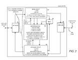
- FIG. 2is a circuit block diagram of the base unit of a wireless repeater system.
- FIG. 3is a circuit block diagram of an uplink circuit in the base unit of FIG. 2 .
- FIG. 4is a circuit block diagram of a CDMA detection circuit in the base unit of FIG. 2 .
- FIG. 5is a circuit block diagram of a mixer circuit in the base unit of FIG. 2 .
- FIG. 6is a circuit block diagram of a downlink circuit in the base unit of FIG. 2 .
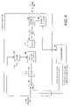
- FIG. 7is a circuit block diagram of a microprocessor circuit in the base unit of FIG. 2 .
- FIG. 8is a logic flow diagram for uplink control in a wireless repeater system.
- FIG. 9is a logic flow diagram for oscillation detection in a wireless repeater system.
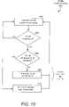
- FIG. 10is a logic flow diagram for uplink power control in a wireless repeater system.
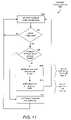
- FIG. 11is a logic flow diagram for downlink power control in a wireless repeater system.
- FIG. 12is a conceptual block diagram of a modular wireless repeater system.
- the modular wireless repeateris typically deployed with a roof-mounted tower-signal antenna and a base unit with a base unit antenna located within the building, with the tower-signal antenna connected to the base unit by a 75 ⁇ coaxial cable.
- the systemallows a customer to purchase a unit for all of the wireless service providers in a given frequency band, such as PCS or Cellular, and then add on modules for additional service providers in other bands that the customer may desire in the future.
- the systemcan also be expanded to accommodate new frequency bands and data modulation techniques that may be implemented in the future.
- this systemuniquely uses 75 ⁇ coaxial cable for satellite television and can, therefore, be installed by any satellite television installer.
- the systemalso detects and prevents low-level oscillations.
- the wireless repeateralso performs intelligent power control in the downlink allowing it to function properly with near and far BTS antennas and in the uplink allowing it to function properly with near and far mobile users.
- the wireless repeateris typically deployed with a roof-mounted tower-signal antenna and a base unit with a base unit antenna located within the building, with the tower-signal antenna connected to the base unit by a 75 ⁇ coaxial cable.
- the tower-signal antennacould be located anywhere that receives acceptable signal power from the wireless BTS antenna
- the base unitmay be located anywhere that provides acceptable signal power to the area where improved service is desired
- any type of communication linkmay be employed to connect the tower-signal antenna to the base unit.
- the communication linkcould use a different type of cable, a telephone line, the house power wiring, a wireless communication link or any other suitable type of communication technique.
- the preferred embodiment of the base unitis shown as analog circuit blocks with a microcontroller, but could be implemented using any suitable type of amplification, power control, and logic circuitry.
- the specific circuit configurationis merely illustrative, and could be replaced by any other circuit configuration that implements equivalent functionality.
- the specific control algorithmscan be replaced by other control algorithms that implement equivalent functionality.
- FIG. 1is a conceptual diagram showing the operating environment for a wireless repeater system 12 installed to provide improved wireless communication service within a customer premises 10 , such as a home or small business.
- the wireless repeater system 12includes a base unit 14 with a base unit antenna 18 , which is typically located inside the customer premises 10 , and a tower-signal antenna 16 , which is typically mounted on the roof of the customer premises.
- the tower-signal antenna 16is connected to the base unit 14 by a cable 20 , typically a readily available 75 ⁇ of the type used for most satellite television systems.
- the wireless repeater system 12implements intelligent power control so that it can automatically adjust its transmission power to be appropriate for communicating with a near tower 24 and a far tower 26 .
- the designation “tower”is meant as a generic terms to include any type of base station antenna location, whether it be a stand-alone tower, a multi-function tower, pole, church bell tower, building or any other suitable location.
- the most common communication signals in the United Statesare 824-849 MHz for Cellular uplink and 869-894 MHz for Cellular downlink, and 1850-1910 MHz for PCS uplink and 1930-1990 MHz for PCS downlink.
- FIG. 2is a circuit block diagram of the base unit 14 of wireless repeater system 12 .
- the base unit 14engages in duplex communications with the tower-signal antenna 16 and the base unit antenna 18 .
- the communication signal from the base unit antenna 18is delivered to a duplexer 30 ; which separates uplink and downlink signals.
- the duplexer 30delivers a signal to an uplink circuit 34 ( FIG. 3 ) that handles incoming uplink signals by filtering and amplifying the incoming signals received from the duplexer 30 .
- the uplink circuit 34delivers an output signal to a mixer 38 ( FIG. 5 ), which combines the signal with another signal from the downlink circuit 36 and delivers the mixed signal to the microprocessor 40 .
- the uplink circuit 34also delivers detected signals to the microprocessor 40 and receives a 5-line uplink power control signal from the microprocessor 40 ( FIG. 7 ).
- the uplink circuit 34also delivers its output communication signal to the second duplexer 32 .
- the communication tower signalis sent from the tower-signal antenna 16 via the 75 ⁇ cable to the duplexer 32 , which separates uplink and downlink signals.
- the duplexer 32delivers a signal to a downlink circuit 36 ( FIG. 6 ) that handles incoming downlink signals by filtering and amplifying the downlink signals received from the duplexer 32 .
- the downlink circuit 36then delivers an output signal to the mixer 38 ( FIG. 5 ), which combines the signal with another signal from the uplink circuit 34 .
- the downlink circuit 36also delivers a downlink power detection signal to the microprocessor 40 ( FIG. 7 ), and delivers its output communication signal to the duplexer 30 .
- FIG. 3is a circuit block diagram of an uplink circuit 34 .
- the signal received from the duplexer 30is received and amplified by an input amplifier 42 .
- the input amplifier 42sends its output signal to a band-pass filter 44 , which passes signals about the range of communication signal carrier frequencies used for the applicable communications systems (e.g., Cellular or PCS, GSM900, DCS, etc).
- the band-pass filter 44sends its output signal to an uplink power control amplifier (or attenuator) 46 , which control the uplink power in response to control signals received from the microprocessor 40 .
- the uplink power control amplifier 46sends its output signal to a crossover frequency notch filter 48 , which ensures adequate isolation between the uplink and downlink amplifiers.
- the crossover frequency notch filter 48sends its output signal to a power amplifier 50 , which sends its output to a power coupler 52 , which sends output power signals to the duplexer 32 and to a level adjuster (e.g. analog attenuator or amplifier) 54 .
- the level adjuster 54sends its output signal to a power detector 56 , which detects the power amplitude envelope in the uplink frequency band.
- the power detector 56sends its output signal to the microprocessor 40 , which implements the oscillation detection and prevention algorithm along with power control.
- the power detector 56also sends an output signal to a CDMA detection circuit 60 , which passes high frequency content signal indicative of CDMA communication signals to the microprocessor 40 .
- the CDMA detection circuit 60sends its output signal to the microprocessor 40 , which implements the oscillation detection and prevention algorithm as noted above.
- the microprocessor 40may send an uplink power control signal (e.g., 5-line digital control latch signal) to the power control amplifier 46 to trim the power in the uplink circuit.
- the microprocessor 40may also send an uplink shut down signal to the input amplifier 42 if the positive feedback oscillation cannot be adequately controlled by the power control amplifier 46 .
- FIG. 4is a circuit block diagram of the CDMA detection circuit 60 .
- the signal from the power amplitude detector 56is received at an amplifier 62 , which amplifies the signal and sends it to a high pass filter 64 , which typically passes signals above 50 kHz.
- the high pass filter 64sends its output signal to a voltage threshold detector 66 , which sends its output signal to the microprocessor 40 .
- FIG. 5is a circuit block diagram of the mixer circuit 58 , which receives input signals from the uplink circuit 34 and the downlink circuit 36 . These signals are amplified by amplifiers 72 and 74 , respectively, and the resulting signals are combined and sent to a band-pass filter that passes the duplex difference signal (e.g. 45 MHz for the Cellular band) to detect whether the signal is a duplex communication signal or a spurious oscillation signal.
- a band-pass filterthat passes the duplex difference signal (e.g. 45 MHz for the Cellular band) to detect whether the signal is a duplex communication signal or a spurious oscillation signal.
- FIG. 6is a circuit block diagram of the downlink circuit 36 .
- the signal received from the duplexer 30is received and amplified by a downlink amplifier 82 .
- the downlink amplifier 82sends its output signal to a band-pass filter 84 , which passes signals about the range of communication signal carrier frequencies used for the applicable communications systems (e.g., Cellular, PCS, GSM900, DCS, etc.).
- the band-pass filter 84sends its output signal to a variable voltage attenuator 86 , which controls the downlink power in response to pulse-width modulated control signals received from the microprocessor 40 via a low-pass filter 96 .
- variable voltage attenuator 86sends its output signal to band pass filter 88 , which passes the carrier frequencies for the applicable communications systems (e.g., Cellular, PCS, GSM900, DCS, etc.).
- the band pass filter 88sends its output signal to an output power amplifier 90 , and then on to a power coupler 92 , which sends output power signals to the duplexer 32 and to a power detector 94 , which detects whether an over power condition is present in the downlink signal.
- the power detector 94sends its output signal to the microprocessor 40 , which implements the power control algorithm.
- the microprocessor 40may send a pulse-width modulated downlink power control signal to the variable voltage attenuator 86 via the low-pass filter 96 .
- the microprocessor 40may also send a downlink shut downlink power control amplifier 82 if the over power condition cannot be adequately controlled by the variable voltage attenuator 86 .
- the specific microprocessor 40 circuit configurationis described in more detail below with reference to FIG. 7 .
- FIG. 7is a circuit block diagram of the microprocessor circuit 40 .
- the microprocessor circuitincludes a central processing unit (CPU) 92 that operates in accordance with a clock signal from the clock 92 .
- the microprocessor circuit 40also includes analog-to-digital processing units (A/D) 94 a - d to convert the analog signals received from the analog circuit components into digital signals for digital processing within the CPU 92 .
- the A/D 92 areceives an analog signal from the uplink power detector 56 and sends a corresponding digital signal to the CPU 92 .
- the A/D 92 breceives an analog signal from the CDMA detector 60 and sends a corresponding digital signal to the CPU 92 .
- the A/D 92 creceives an analog signal from the mixer 38 and sends a corresponding digital signal to the CPU 92 .
- the A/D 92 dreceives an analog signal from the downlink power detector 94 and sends a corresponding digital signal to the CPU 92 .
- the central processing unit (CPU) 92sends uplink power control signals to the uplink power control amplifier 46 .
- the central processing unit (CPU) 92also sends uplink power shut down signals to the uplink power control amplifier 42 .
- the central processing unit (CPU) 92sends pulse-width modulated downlink power control signals to the variable voltage attenuator 86 via the low-pass filter 96 .
- the central processing unit (CPU) 92also sends downlink power shut down signals to the downlink power control amplifier 82 .
- the specific microprocessor 40 control algorithmis described in more detail below with reference to FIGS. 8-11 .
- FIG. 8is a logic flow diagram showing Routine 100 for detecting a small or latent oscillation that may be indicative of an impending positive feedback situation.
- the microprocessor 40monitors the uplink signals to detect an oscillation that may be indicative of a positive feedback situation.
- Step 102is followed by step 104 , in which the microprocessor 40 determines whether an oscillation is present. If an oscillation is not present, the “NO” branch is followed back to step 102 , and the microprocessor 40 continues to monitor the uplink power. If an oscillation is present, the “YES” branch is followed to step 106 , in which the microprocessor 40 determines whether the uplink attenuation is at its maximum value.
- step 108the microprocessor 40 increments the attenuation signal to the uplink power control amplifier 46 ( FIG. 3 ) typically by 6 dB.
- the microprocessor 40may loop through this control process several times to implement stepped attenuation, for example using the 5-line latch signal to sequentially increase the attenuation applied by the uplink power control amplifier 46 from zero to 30 dB in 6 dB increments.
- Step 108is followed by step 110 , in which the microprocessor 40 waits two minutes and then loops back to step 102 , and the microprocessor 40 continues to monitor the uplink power.
- step 106If the uplink attenuation is at its maximum value, the “YES” branch is followed from step 106 to step 112 , in which the in which the microprocessor 40 sends a shut down signal to the uplink input filter 42 . Routine 200 then loops back to step 102 when the base unit is reset after the installer corrects the antenna isolation (separation).
- FIG. 9is a logic flow diagram for oscillation detection Routine 102 (i.e., step 102 in FIG. 8 ).
- the microprocessor 40determines whether a CDMA signal has been detected by determining whether the uplink signal contains a high frequency component indicative of a CDMA signal. See FIG. 4 . If a CDMA signal is detected, the microprocessor 40 deems that the uplink signal does not contain a positive feedback oscillation, and the “YES” branch is followed to stop 124 and normal operation continues.
- step 120determines whether an analog duplex (e.g., AMPS) signal has been detected by determining whether the uplink signal contains a difference signal indicative of analog duplex communications signals. See FIG. 5 . If an analog duplex signal is detected, the microprocessor 40 deems that the uplink signal does not contain a positive feedback oscillation, and the “YES” branch is followed to stop 124 and normal operation continues.
- an analog duplexe.g., AMPS
- step 122determines whether a pulsed signal indicative of TDMA encoded communication signals has been detected by determining if a pulse of predetermined amplitude is present in the uplink signal. See FIG. 3 , power detector 56 . If a pulsed signal is detected, the microprocessor 40 deems that the uplink signal does not contain a positive feedback oscillation, and the “YES” branch is followed to stop 124 and normal operation continues. If a pulsed signal is NOT detected, then the “NO” is followed from step 122 to step 128 , in which the microprocessor 40 deems that a positive feedback oscillation has been detected. In this case, the microprocessor 40 implements uplink ( FIG. 8 ) and downlink ( FIG. 10 ) power control.
- FIG. 10is a logic flow diagram showing Routine 200 for controlling the uplink power in response to an over power situation (e.g., the mobile user device is too close to the base unit antenna).
- the microprocessor 40monitors the uplink signals to detect excessive power.
- Step 202is followed by step 204 , in which the microprocessor 40 determines whether the uplink power is above a predetermined threshold value. If the uplink power is above a predetermined threshold value, the “NO” branch is followed back to step 202 , and the microprocessor 40 continues to monitor the uplink power. If an excess power is present, the “YES” branch is followed to step 206 , in which the microprocessor 40 determines whether the uplink attenuation is at its maximum value.
- step 108the microprocessor 40 increments the attenuation signal to the uplink power control amplifier 46 ( FIG. 3 ), typically by 1 dB.
- the microprocessor 40may loop through this control process several times to implement stepped attenuation, for example using the 5-line latch signal to sequentially increase the attenuation applied by the uplink power control amplifier 46 from zero to 30 dB in 1 dB increments.
- step 208the microprocessor 40 loops back to step 202 and the microprocessor 40 continues to monitor the uplink power.
- step 206If the uplink attenuation is at its maximum value, the “YES” branch is followed from step 206 to step 210 , in which the microprocessor 40 sends a shut down signal to the uplink input filter 42 . Routine 200 then waits 10 seconds and then loops back to step 202 when the base unit is reset.
- FIG. 11is a logic flow diagram showing Routine 300 for controlling the downlink power in response to an over power situation.
- the microprocessor 40monitors the downlink signals to detect excess power that may be indicative of a very near BTS antenna.
- Step 302is followed by step 304 , in which the microprocessor 40 determines the downlink power is above a predetermined threshold value. If the downlink power is above a predetermined threshold value, the “NO” branch is followed back to step 302 , and the microprocessor 40 continues to monitor the downlink power. If excess power is present, the “YES” branch is followed to step 306 , in which the microprocessor 40 determines whether the downlink attenuation is at its maximum value.
- step 308the microprocessor 40 increments the attenuation signal to the variable voltage attenuator 86 ( FIG. 6 ), typically by 1 dB.
- step 308is followed by step 310 , in which the microprocessor 40 also increments the attenuation signal to the uplink power control amplifier 46 ( FIG. 3 ), typically by 1 dB in order to keep the communication link balanced.
- the microprocessor 40may loop through this control process several times to implement stepped attenuation, for example using a pulse-width modulation to sequentially increase the attenuation applied by the downlink variable voltage attenuator 86 , and using the 5-line latch signal to sequentially increase the attenuation applied by the uplink power control amplifier 46 , the step the uplink and downlink attenuation from zero to 20 dB in 1 dB increments. After step 310 the microprocessor 40 loops back to step 302 and the microprocessor 40 continues to monitor the downlink power.
- step 306the “YES” branch is followed from step 306 to step 312 , in which the microprocessor 40 sends a shut down signal to the downlink amplifier 42 .
- Routine 300then waits two minutes and then loops back to step 302 when the base unit is reset.
- FIG. 12is a conceptual block diagram of a modular wireless repeater system that includes a dual-band tower-signal antenna 400 connected to an upgradable base unit 404 by way of a 75 ⁇ coaxial cable 402 .
- the upgradable base unit 404which includes a Cellular system (e.g., 800 MHz) base unit antenna 406 , is configured to implement wireless repeater functions for a Cellular band system.
- the upgradable base unit 404includes a diplexer 407 to split Cellular signals from PCS signals and a switch 420 to activate pass-through connectivity to an output port for PCS signals.
- An add-on PCS base unit 414 with a PCS base unit antenna 416may be connected to the output port of the upgradable base unit 404 to receive the PCS band signals passed through the upgradable base unit.
- the cables 402are standard 75 ⁇ coaxial cables, and the ports on the upgradable base unit 404 and the add-on base unit 414 are also standard for 75 ⁇ coaxial cable.
- the upgradable base unit 404could be operative for PCS system signals, or signals for any other wireless communication system.
- the add-on base unitmay be operative for Cellular system signals, or signals for any other wireless communication system.
- any number of add-on base unitsmay be piggy-backed together to create a modular wireless repeater that may be augmented to meet the customer's needs as they change over time.
Landscapes
- Engineering & Computer Science (AREA)
- Computer Networks & Wireless Communication (AREA)
- Signal Processing (AREA)
- Mobile Radio Communication Systems (AREA)
- Radio Relay Systems (AREA)
Abstract
Description
Claims (32)
Priority Applications (1)
| Application Number | Priority Date | Filing Date | Title |
|---|---|---|---|
| US11/138,010US7706744B2 (en) | 2004-05-26 | 2005-05-26 | Wireless repeater implementing low-level oscillation detection and protection for a duplex communication system |
Applications Claiming Priority (2)
| Application Number | Priority Date | Filing Date | Title |
|---|---|---|---|
| US57442804P | 2004-05-26 | 2004-05-26 | |
| US11/138,010US7706744B2 (en) | 2004-05-26 | 2005-05-26 | Wireless repeater implementing low-level oscillation detection and protection for a duplex communication system |
Publications (2)
| Publication Number | Publication Date |
|---|---|
| US20050272367A1 US20050272367A1 (en) | 2005-12-08 |
| US7706744B2true US7706744B2 (en) | 2010-04-27 |
Family
ID=34971497
Family Applications (1)
| Application Number | Title | Priority Date | Filing Date |
|---|---|---|---|
| US11/138,010Active2027-10-13US7706744B2 (en) | 2004-05-26 | 2005-05-26 | Wireless repeater implementing low-level oscillation detection and protection for a duplex communication system |
Country Status (5)
| Country | Link |
|---|---|
| US (1) | US7706744B2 (en) |
| EP (1) | EP1756971B1 (en) |
| AU (1) | AU2005251169B2 (en) |
| CA (1) | CA2568422C (en) |
| WO (1) | WO2005119936A2 (en) |
Cited By (19)
| Publication number | Priority date | Publication date | Assignee | Title |
|---|---|---|---|---|
| US20080293360A1 (en)* | 2007-05-22 | 2008-11-27 | Nikolai Maslennikov | On frequency repeater with AGC stability determination |
| AU2005251169B2 (en)* | 2004-05-26 | 2010-07-15 | Zboost, Llc | Wireless repeater for a duplex communication system implementing a protection based on oscillation detection |
| US20130301688A1 (en)* | 2012-05-13 | 2013-11-14 | Amir Keyvan Khandani | Full Duplex Wireless Transmission with Channel Phase-Based Encryption |
| WO2016014787A1 (en)* | 2014-07-23 | 2016-01-28 | Wilson Electronics, Llc | Multiple-port signal boosters |
| US9402190B2 (en) | 2013-04-29 | 2016-07-26 | Cellphone-Mate, Inc. | Apparatus and methods for radio frequency signal boosters |
| US9413516B2 (en) | 2013-11-30 | 2016-08-09 | Amir Keyvan Khandani | Wireless full-duplex system and method with self-interference sampling |
| US9479322B2 (en) | 2013-11-30 | 2016-10-25 | Amir Keyvan Khandani | Wireless full-duplex system and method using sideband test signals |
| US9820311B2 (en) | 2014-01-30 | 2017-11-14 | Amir Keyvan Khandani | Adapter and associated method for full-duplex wireless communication |
| US9997830B2 (en) | 2012-05-13 | 2018-06-12 | Amir Keyvan Khandani | Antenna system and method for full duplex wireless transmission with channel phase-based encryption |
| WO2018144940A1 (en)* | 2017-02-02 | 2018-08-09 | Wilson Electronics, Llc | Band-specific detection in a signal booster |
| US10177896B2 (en) | 2013-05-13 | 2019-01-08 | Amir Keyvan Khandani | Methods for training of full-duplex wireless systems |
| US10298181B2 (en)* | 2015-06-15 | 2019-05-21 | Nec Corporation | Low-noise amplification device, method, and attenuation adjustment program |
| US10333593B2 (en) | 2016-05-02 | 2019-06-25 | Amir Keyvan Khandani | Systems and methods of antenna design for full-duplex line of sight transmission |
| US10630374B2 (en) | 2017-04-06 | 2020-04-21 | Wilson Electronics, Llc | Allocating and adjusting power between active ports of a multi-port booster |
| US10659142B1 (en) | 2018-12-04 | 2020-05-19 | Wilson Electronics, Llc | Independent band detection for network protection |
| US10700766B2 (en) | 2017-04-19 | 2020-06-30 | Amir Keyvan Khandani | Noise cancelling amplify-and-forward (in-band) relay with self-interference cancellation |
| US10924253B2 (en)* | 2017-12-18 | 2021-02-16 | Arris Enterprises Llc | Full duplex expander in a full duplex network |
| US11012144B2 (en) | 2018-01-16 | 2021-05-18 | Amir Keyvan Khandani | System and methods for in-band relaying |
| US11057204B2 (en) | 2017-10-04 | 2021-07-06 | Amir Keyvan Khandani | Methods for encrypted data communications |
Families Citing this family (29)
| Publication number | Priority date | Publication date | Assignee | Title |
|---|---|---|---|---|
| US7280799B1 (en)* | 2004-08-18 | 2007-10-09 | Broadlink Research Inc. | Mobile phone repeater |
| US7532863B2 (en)* | 2004-10-25 | 2009-05-12 | Raytheon Company | Broadband wireless ad-hoc modem and network testbed |
| US20060189276A1 (en)* | 2004-12-08 | 2006-08-24 | Michael Halinski | Methods and systems for intelligent adaptive gain control |
| US7633998B2 (en)* | 2004-12-21 | 2009-12-15 | Delphi Technologies, Inc. | Wireless home repeater for satellite radio products |
| JP4567480B2 (en)* | 2005-02-04 | 2010-10-20 | 富士通株式会社 | Signal transmission system and signal transmission method |
| KR100646117B1 (en)* | 2005-09-06 | 2006-11-14 | 주식회사 에이로직스 | Micro oscillation detection method and apparatus, WiBro repeater provided with the apparatus |
| US7409186B2 (en)* | 2006-07-13 | 2008-08-05 | Wilson Electronics, Inc. | Detection and elimination of oscillation within cellular network amplifiers |
| US7486929B2 (en)* | 2006-07-13 | 2009-02-03 | Wilson Electronics, Inc. | Processor-controlled variable gain cellular network amplifiers with oscillation detection circuit |
| US7729669B2 (en)* | 2006-09-26 | 2010-06-01 | Wilson Electronics | Processor controlled variable gain cellular network amplifier |
| US20090154446A1 (en)* | 2007-12-14 | 2009-06-18 | Infineon Technologies Ag | Data frame, telegram, method for controlling an rf-transceiver and mobile communication system |
| US8391875B1 (en)* | 2008-02-22 | 2013-03-05 | Sprint Spectrum L.P. | Method and system for extending MIMO wireless service |
| WO2010017180A1 (en)* | 2008-08-04 | 2010-02-11 | Wireless Extenders, Inc. | A bi-directional repeater with a single local oscillator and frequency synthesizer |
| US8660165B2 (en)* | 2009-06-11 | 2014-02-25 | Andrew Llc | System and method for detecting spread spectrum signals in a wireless environment |
| US8223821B2 (en)* | 2009-06-25 | 2012-07-17 | Andrew Llc | Uplink signal detection in RF repeaters |
| US8583033B2 (en)* | 2010-03-05 | 2013-11-12 | Wilson Electronics, Llc | Oscillation protected amplifier with base station overload and noise floor protection |
| US8849187B2 (en) | 2011-08-23 | 2014-09-30 | Wilson Electronics, Llc | Radio frequency amplifier noise reduction system |
| US8874030B2 (en) | 2011-08-23 | 2014-10-28 | Wilson Electronics, Llc | Oscillation detection and oscillation mitigation in amplifiers |
| US8874029B2 (en) | 2011-08-23 | 2014-10-28 | Wilson Electronics, Llc | Verifying oscillation in amplifiers and the mitigation thereof |
| US8583034B2 (en) | 2011-08-23 | 2013-11-12 | Wilson Electronics, Llc | Verifying and mitigating oscillation in amplifiers |
| US8639180B2 (en) | 2011-08-23 | 2014-01-28 | Wilson Electronics, Llc | Verifying and mitigating oscillation in amplifiers |
| AU2014284691B2 (en)* | 2013-07-03 | 2017-05-18 | Wilson Electronics, Llc | Remote control application for wireless booster |
| US20170163233A1 (en)* | 2014-07-23 | 2017-06-08 | Wilson Electronics, Llc | Multiple-port signal boosters |
| US20190386625A1 (en)* | 2013-07-03 | 2019-12-19 | Wilson Electronics, Llc | Multiple-port signal booster |
| CN105187125A (en)* | 2015-09-30 | 2015-12-23 | 浙江生辉照明有限公司 | LED lighting device and signal amplifying system based on LED lighting device |
| CN109565854B (en) | 2016-08-03 | 2022-06-17 | Lg 电子株式会社 | Method of terminal performing uplink communication in wireless communication system and terminal using the same |
| CA3037957A1 (en) | 2016-09-23 | 2018-03-29 | Wilson Electronics, Llc | Booster with an integrated satellite location system module |
| CN110537338A (en) | 2017-04-11 | 2019-12-03 | 威尔逊电子有限责任公司 | Signal Booster with coaxial cable connection |
| US10673518B2 (en) | 2017-06-27 | 2020-06-02 | Wilson Electronics, Llc | Crossover isolation reduction in a signal booster |
| US11910328B2 (en)* | 2021-07-01 | 2024-02-20 | Qualcomm Incorporated | Applying amplitude drooping for adjacent bands |
Citations (82)
| Publication number | Priority date | Publication date | Assignee | Title |
|---|---|---|---|---|
| US2258586A (en) | 1938-04-09 | 1941-10-14 | Bosch Gmbh Robert | Electromagnetically operated petrol supply pump |
| US4549293A (en)* | 1983-12-29 | 1985-10-22 | The United States Of America As Represented By The Secretary Of The Army | Time division multiple access communications system |
| US4677687A (en) | 1984-06-22 | 1987-06-30 | Nec Corporation | Method of establishing communication relay between mobile unit and land site and booster used therefor |
| US4704733A (en) | 1985-12-16 | 1987-11-03 | Minoru Kawano | Cell enhancer for cellular radio telephone system having diversity function |
| US4754495A (en) | 1985-12-16 | 1988-06-28 | Minori Kawano | Cell enhancer for cellular radio telephone system having bandpass filter arrangement |
| US4849963A (en) | 1985-10-15 | 1989-07-18 | Minori Kawano | Cellular radio telephone enhancement circuit |
| US4941200A (en) | 1987-08-03 | 1990-07-10 | Orion Industries, Inc. | Booster |
| US5095528A (en) | 1988-10-28 | 1992-03-10 | Orion Industries, Inc. | Repeater with feedback oscillation control |
| US5164985A (en)* | 1987-10-27 | 1992-11-17 | Nysen Paul A | Passive universal communicator system |
| GB2258586A (en) | 1991-08-05 | 1993-02-10 | Mercury Personal Communication | Radio signal enhancer |
| US5222246A (en)* | 1990-11-02 | 1993-06-22 | General Electric Company | Parallel amplifiers with combining phase controlled from combiner difference port |
| US5574967A (en)* | 1994-01-11 | 1996-11-12 | Ericsson Ge Mobile Communications, Inc. | Waste energy control and management in power amplifiers |
| US5812933A (en)* | 1992-12-30 | 1998-09-22 | Radio Communication Systems Ltd. | Duplex RF repeater for personal communications system |
| US5815795A (en)* | 1995-08-25 | 1998-09-29 | Sumitomo Electric Industries, Ltd. | Oscillation detecting system for wireless repeater |
| US5835848A (en)* | 1996-12-30 | 1998-11-10 | Lucent Technologies Inc. | Range repeater for a transmission system |
| US5860057A (en)* | 1995-03-15 | 1999-01-12 | Hitachi, Ltd. | Satellite communications system and method |
| US5883884A (en)* | 1996-04-22 | 1999-03-16 | Roger F. Atkinson | Wireless digital communication system having hierarchical wireless repeaters with autonomous hand-off |
| US5991693A (en)* | 1996-02-23 | 1999-11-23 | Mindcraft Technologies, Inc. | Wireless I/O apparatus and method of computer-assisted instruction |
| US6009324A (en) | 1996-03-04 | 1999-12-28 | Allgon Ab | Method and device for monitoring a mobile telephone repeater |
| US6023612A (en)* | 1996-07-05 | 2000-02-08 | Thomcast Communications, Inc. | Modular transmission system and method |
| US6222503B1 (en)* | 1997-01-10 | 2001-04-24 | William Gietema | System and method of integrating and concealing antennas, antenna subsystems and communications subsystems |
| US20010038670A1 (en)* | 1999-12-17 | 2001-11-08 | U. S. Philips Corporation | Multibit spread spectrum signalling |
| US20020028655A1 (en)* | 2000-07-14 | 2002-03-07 | Rosener Douglas K. | Repeater system |
| US6385435B1 (en)* | 2000-04-20 | 2002-05-07 | Jhong Sam Lee | Coupled interference concellation system for wideband repeaters in a cellular system |
| US20020090974A1 (en)* | 2000-10-26 | 2002-07-11 | Peter Hagn | Combined front-end circuit for wireless transmission systems |
| US20020119749A1 (en)* | 2001-02-28 | 2002-08-29 | Young-Min Oh | Repeater system having oscillation preventing function and automatic reverse output disabling function for non-subscriber and control method thereof |
| US20020155838A1 (en)* | 2000-06-19 | 2002-10-24 | Durrant Randolph L. | RF signal repeater, mobile unit position determination system using the RF signal repeater, and method of communication therefor |
| US20020193108A1 (en)* | 2001-05-10 | 2002-12-19 | Robinett Robert L. | Multi-mode satellite and terrestrial communication device with position location |
| US6567645B1 (en)* | 2000-08-28 | 2003-05-20 | Globalstar L.P. | Multiple satellite repeater management system using frame error rate for diversity selection |
| US6570858B1 (en)* | 1999-11-01 | 2003-05-27 | Motorola, Inc. | Satellite-based communications system with terrestrial repeater and method therefor |
| US20030104781A1 (en) | 2001-12-03 | 2003-06-05 | Son O. Sung | Modular residential radio frequency converting repeater |
| US20030123401A1 (en)* | 2001-11-20 | 2003-07-03 | Dean Richard F. | Reverse link power controlled repeater |
| US20030157885A1 (en)* | 2002-02-04 | 2003-08-21 | Jeffrey Lukkarila | CATV amplifier bypass repeater for digital data and systems including same |
| US20030232595A1 (en)* | 2002-04-17 | 2003-12-18 | Baker Michael R. | Wireless repeater apparatus, system, and method |
| US6671502B1 (en)* | 1999-03-31 | 2003-12-30 | Harada Industry Co., Ltd. | Control device for radio repeater in communication field |
| US6690657B1 (en)* | 2000-02-25 | 2004-02-10 | Berkeley Concept Research Corporation | Multichannel distributed wireless repeater network |
| US20040097189A1 (en) | 2000-10-18 | 2004-05-20 | Spotwave Wireless, Inc. | Adaptive personal repeater |
| US20040102219A1 (en)* | 1999-11-29 | 2004-05-27 | Bunton John David | Communications system |
| US6745003B1 (en) | 1999-07-20 | 2004-06-01 | Andrew Corporation | Adaptive cancellation for wireless repeaters |
| US20040110469A1 (en)* | 2000-01-14 | 2004-06-10 | Judd Mano D. | Repeaters for wireless communication systems |
| US6768897B1 (en)* | 1997-09-30 | 2004-07-27 | Nokia Networks Oy | Method of adjusting frequency of cellular radio repeater |
| US20040146013A1 (en)* | 2003-01-22 | 2004-07-29 | Hong Kong Applied Science And Technology Research Institute Co., Ltd | Wireless local area network time division duplex relay system with high speed automatic up-link and down-link detection |
| US20040156097A1 (en)* | 2003-02-06 | 2004-08-12 | Spotwave Wireless Inc. | Intelligent gain control in an on-frequency repeater |
| US20040166802A1 (en)* | 2003-02-26 | 2004-08-26 | Ems Technologies, Inc. | Cellular signal enhancer |
| US20040176026A1 (en)* | 2002-06-21 | 2004-09-09 | Tantivy Communications, Inc. | Covert spatially separated antenna package for repeater |
| US20040185794A1 (en)* | 2003-01-30 | 2004-09-23 | Chang-Rae Jeong | Multi-sector in-building repeater |
| US20040192194A1 (en)* | 2002-08-02 | 2004-09-30 | Radio Frequency Systems, Inc. | Dual band bidirectional amplifier for wireless communication |
| US20040219876A1 (en)* | 2002-12-05 | 2004-11-04 | Baker Kenneth Robert | System and method for setting the reverse link gain of repeaters in wireless communications systems |
| US20040235417A1 (en)* | 2003-02-24 | 2004-11-25 | Dean Richard F. | Repeater oscillation prevention |
| US20040247040A1 (en)* | 2003-06-04 | 2004-12-09 | Anthony Dennis | Electromagnetic wave transmitter systems, methods and articles of manufacture |
| US20040247047A1 (en)* | 2003-06-04 | 2004-12-09 | Anthony Dennis | Electromagnetic wave transmitter systems, methods and articles of manufacture |
| US20040259497A1 (en)* | 2000-07-26 | 2004-12-23 | Dent Paul W. | Satellite communications system using multiple earth stations |
| US6838989B1 (en)* | 1999-12-22 | 2005-01-04 | Intermec Ip Corp. | RFID transponder having active backscatter amplifier for re-transmitting a received signal |
| US20050048993A1 (en)* | 2003-08-13 | 2005-03-03 | Xytrans, Inc. | Toneless telemetry in a wireless system |
| US20050118949A1 (en)* | 2003-09-16 | 2005-06-02 | Spotwave Wireless Inc. | Method for detecting an oscillation in an on-frequency repeater |
| US6915141B2 (en)* | 1999-08-25 | 2005-07-05 | Skyworks Solutions, Inc. | Secondary automatic gain control loops for direct conversion CDMA receivers |
| US6985451B1 (en)* | 1997-10-14 | 2006-01-10 | Alvarion Israel (2003) Ltd. | Method and apparatus for baseband transmission between a top floor unit and an outdoor unit in a terminal for a wireless metropolitan area network |
| US6993287B2 (en)* | 2003-03-04 | 2006-01-31 | Four Bars Clarity, Llc | Repeater system for strong signal environments |
| US20060026017A1 (en)* | 2003-10-28 | 2006-02-02 | Walker Richard C | National / international management and security system for responsible global resourcing through technical management to brige cultural and economic desparity |
| US20060041680A1 (en)* | 2002-10-11 | 2006-02-23 | Proctor Jr James A | Reducing loop effects in a wireless local area network repeater |
| US20060056352A1 (en)* | 2002-11-15 | 2006-03-16 | Widefi, Inc. | Wireless local area network repeater with detection |
| US20060084379A1 (en)* | 2003-03-04 | 2006-04-20 | O'neill Frank P | Repeater system for strong signal environments |
| US7035587B1 (en)* | 2002-03-14 | 2006-04-25 | Sprint Spectrum L.P. | Method and system for decreasing noise from wireless repeaters |
| US7043199B2 (en)* | 2001-06-06 | 2006-05-09 | Hughes Network Systems Llc | Uplink power control system for satellite communication system employing on-board satellite processing and fade estimation |
| US7088953B2 (en)* | 2000-10-18 | 2006-08-08 | Spotwave Wireless Canada Inc. | Coverage area signature in an on-frequency repeater |
| US20060205342A1 (en)* | 2005-03-11 | 2006-09-14 | Mckay David L Sr | Remotely controllable and reconfigurable wireless repeater |
| US20060240769A1 (en)* | 2004-04-06 | 2006-10-26 | Proctor Jr James A | Transmission canceller for wireless local area network |
| US20070010198A1 (en)* | 1999-12-07 | 2007-01-11 | Mckay David L Sr | Method and apparatus for utilizing selective signal polarization and interference cancellation for wireless communication |
| US20070066220A1 (en)* | 2004-05-13 | 2007-03-22 | Widefi, Inc. | Non-frequency translating repeater with downlink detection for uplink and downlink synchronization |
| US7251459B2 (en)* | 2002-05-03 | 2007-07-31 | Atheros Communications, Inc. | Dual frequency band wireless LAN |
| US7254379B2 (en)* | 2004-07-09 | 2007-08-07 | Silicon Storage Technology, Inc. | RF receiver mismatch calibration system and method |
| US20070211786A1 (en)* | 1998-02-12 | 2007-09-13 | Steve Shattil | Multicarrier Sub-Layer for Direct Sequence Channel and Multiple-Access Coding |
| US7283840B2 (en)* | 2003-02-07 | 2007-10-16 | Chrontel, Inc. | Reconfigurable analog baseband for a single-chip dual-mode transceiver |
| US20070241812A1 (en)* | 2002-05-01 | 2007-10-18 | Dali Systems Co. Ltd. | High efficiency linearization power amplifier for wireless communication |
| US20080002709A1 (en)* | 2001-03-20 | 2008-01-03 | Lightwaves Systems, Inc. | High bandwidth data transport system |
| US20080057880A1 (en)* | 2006-08-31 | 2008-03-06 | Texas Instruments Incorporated | System and method for preprocessing a signal for transmission by a power amplifier |
| US20080265996A1 (en)* | 2002-05-01 | 2008-10-30 | Dali Systems Co., Ltd | Digital Hybrid Mode Power Amplifier System |
| US20080293360A1 (en)* | 2007-05-22 | 2008-11-27 | Nikolai Maslennikov | On frequency repeater with AGC stability determination |
| US20090086655A1 (en)* | 2007-09-29 | 2009-04-02 | Ghadaksaz Michael M | Portable wireless repeater system for indoor wireless coverage enhancement of residential, small office, and vehicular applications |
| US20090110033A1 (en)* | 1998-02-12 | 2009-04-30 | Lot 41 Acquisition Foundation, Llc | Multicarrier sub-layer for direct sequence channel and multiple-access coding |
| US7555136B2 (en)* | 2004-06-25 | 2009-06-30 | Victorion Technology Co., Ltd. | Nasal bone conduction wireless communication transmitting device |
| US7627287B2 (en)* | 2005-05-20 | 2009-12-01 | British Broadcasting Corporation | On-channel repeater |
Family Cites Families (1)
| Publication number | Priority date | Publication date | Assignee | Title |
|---|---|---|---|---|
| US7706744B2 (en)* | 2004-05-26 | 2010-04-27 | Wireless Extenders, Inc. | Wireless repeater implementing low-level oscillation detection and protection for a duplex communication system |
- 2005
- 2005-05-26USUS11/138,010patent/US7706744B2/enactiveActive
- 2005-05-26EPEP05755482.6Apatent/EP1756971B1/ennot_activeExpired - Lifetime
- 2005-05-26WOPCT/US2005/018611patent/WO2005119936A2/enactiveApplication Filing
- 2005-05-26AUAU2005251169Apatent/AU2005251169B2/ennot_activeCeased
- 2005-05-26CACA2568422Apatent/CA2568422C/ennot_activeExpired - Lifetime
Patent Citations (88)
| Publication number | Priority date | Publication date | Assignee | Title |
|---|---|---|---|---|
| US2258586A (en) | 1938-04-09 | 1941-10-14 | Bosch Gmbh Robert | Electromagnetically operated petrol supply pump |
| US4549293A (en)* | 1983-12-29 | 1985-10-22 | The United States Of America As Represented By The Secretary Of The Army | Time division multiple access communications system |
| US4677687A (en) | 1984-06-22 | 1987-06-30 | Nec Corporation | Method of establishing communication relay between mobile unit and land site and booster used therefor |
| US4849963A (en) | 1985-10-15 | 1989-07-18 | Minori Kawano | Cellular radio telephone enhancement circuit |
| US4704733A (en) | 1985-12-16 | 1987-11-03 | Minoru Kawano | Cell enhancer for cellular radio telephone system having diversity function |
| US4754495A (en) | 1985-12-16 | 1988-06-28 | Minori Kawano | Cell enhancer for cellular radio telephone system having bandpass filter arrangement |
| US4941200A (en) | 1987-08-03 | 1990-07-10 | Orion Industries, Inc. | Booster |
| US5164985A (en)* | 1987-10-27 | 1992-11-17 | Nysen Paul A | Passive universal communicator system |
| US5095528A (en) | 1988-10-28 | 1992-03-10 | Orion Industries, Inc. | Repeater with feedback oscillation control |
| US5222246A (en)* | 1990-11-02 | 1993-06-22 | General Electric Company | Parallel amplifiers with combining phase controlled from combiner difference port |
| GB2258586A (en) | 1991-08-05 | 1993-02-10 | Mercury Personal Communication | Radio signal enhancer |
| US5812933A (en)* | 1992-12-30 | 1998-09-22 | Radio Communication Systems Ltd. | Duplex RF repeater for personal communications system |
| US5574967A (en)* | 1994-01-11 | 1996-11-12 | Ericsson Ge Mobile Communications, Inc. | Waste energy control and management in power amplifiers |
| US5860057A (en)* | 1995-03-15 | 1999-01-12 | Hitachi, Ltd. | Satellite communications system and method |
| US5815795A (en)* | 1995-08-25 | 1998-09-29 | Sumitomo Electric Industries, Ltd. | Oscillation detecting system for wireless repeater |
| US5991693A (en)* | 1996-02-23 | 1999-11-23 | Mindcraft Technologies, Inc. | Wireless I/O apparatus and method of computer-assisted instruction |
| US6009324A (en) | 1996-03-04 | 1999-12-28 | Allgon Ab | Method and device for monitoring a mobile telephone repeater |
| US5883884A (en)* | 1996-04-22 | 1999-03-16 | Roger F. Atkinson | Wireless digital communication system having hierarchical wireless repeaters with autonomous hand-off |
| US6023612A (en)* | 1996-07-05 | 2000-02-08 | Thomcast Communications, Inc. | Modular transmission system and method |
| US5835848A (en)* | 1996-12-30 | 1998-11-10 | Lucent Technologies Inc. | Range repeater for a transmission system |
| US6222503B1 (en)* | 1997-01-10 | 2001-04-24 | William Gietema | System and method of integrating and concealing antennas, antenna subsystems and communications subsystems |
| US6768897B1 (en)* | 1997-09-30 | 2004-07-27 | Nokia Networks Oy | Method of adjusting frequency of cellular radio repeater |
| US6985451B1 (en)* | 1997-10-14 | 2006-01-10 | Alvarion Israel (2003) Ltd. | Method and apparatus for baseband transmission between a top floor unit and an outdoor unit in a terminal for a wireless metropolitan area network |
| US20090110033A1 (en)* | 1998-02-12 | 2009-04-30 | Lot 41 Acquisition Foundation, Llc | Multicarrier sub-layer for direct sequence channel and multiple-access coding |
| US7430257B1 (en)* | 1998-02-12 | 2008-09-30 | Lot 41 Acquisition Foundation, Llc | Multicarrier sub-layer for direct sequence channel and multiple-access coding |
| US7593449B2 (en)* | 1998-02-12 | 2009-09-22 | Steve Shattil | Multicarrier sub-layer for direct sequence channel and multiple-access coding |
| US20070211786A1 (en)* | 1998-02-12 | 2007-09-13 | Steve Shattil | Multicarrier Sub-Layer for Direct Sequence Channel and Multiple-Access Coding |
| US6671502B1 (en)* | 1999-03-31 | 2003-12-30 | Harada Industry Co., Ltd. | Control device for radio repeater in communication field |
| US6745003B1 (en) | 1999-07-20 | 2004-06-01 | Andrew Corporation | Adaptive cancellation for wireless repeaters |
| US6915141B2 (en)* | 1999-08-25 | 2005-07-05 | Skyworks Solutions, Inc. | Secondary automatic gain control loops for direct conversion CDMA receivers |
| US6570858B1 (en)* | 1999-11-01 | 2003-05-27 | Motorola, Inc. | Satellite-based communications system with terrestrial repeater and method therefor |
| US20040102219A1 (en)* | 1999-11-29 | 2004-05-27 | Bunton John David | Communications system |
| US20070010198A1 (en)* | 1999-12-07 | 2007-01-11 | Mckay David L Sr | Method and apparatus for utilizing selective signal polarization and interference cancellation for wireless communication |
| US20010038670A1 (en)* | 1999-12-17 | 2001-11-08 | U. S. Philips Corporation | Multibit spread spectrum signalling |
| US6838989B1 (en)* | 1999-12-22 | 2005-01-04 | Intermec Ip Corp. | RFID transponder having active backscatter amplifier for re-transmitting a received signal |
| US20040110469A1 (en)* | 2000-01-14 | 2004-06-10 | Judd Mano D. | Repeaters for wireless communication systems |
| US6690657B1 (en)* | 2000-02-25 | 2004-02-10 | Berkeley Concept Research Corporation | Multichannel distributed wireless repeater network |
| US6385435B1 (en)* | 2000-04-20 | 2002-05-07 | Jhong Sam Lee | Coupled interference concellation system for wideband repeaters in a cellular system |
| US20020155838A1 (en)* | 2000-06-19 | 2002-10-24 | Durrant Randolph L. | RF signal repeater, mobile unit position determination system using the RF signal repeater, and method of communication therefor |
| US20020028655A1 (en)* | 2000-07-14 | 2002-03-07 | Rosener Douglas K. | Repeater system |
| US20040259497A1 (en)* | 2000-07-26 | 2004-12-23 | Dent Paul W. | Satellite communications system using multiple earth stations |
| US7305211B2 (en)* | 2000-07-26 | 2007-12-04 | Ericsson Inc. | Satellite communications system using multiple earth stations |
| US6567645B1 (en)* | 2000-08-28 | 2003-05-20 | Globalstar L.P. | Multiple satellite repeater management system using frame error rate for diversity selection |
| US7088953B2 (en)* | 2000-10-18 | 2006-08-08 | Spotwave Wireless Canada Inc. | Coverage area signature in an on-frequency repeater |
| US20040097189A1 (en) | 2000-10-18 | 2004-05-20 | Spotwave Wireless, Inc. | Adaptive personal repeater |
| US6889033B2 (en)* | 2000-10-18 | 2005-05-03 | Spotwave Wireless Inc. | Intelligent gain control in an on-frequency repeater |
| US20020090974A1 (en)* | 2000-10-26 | 2002-07-11 | Peter Hagn | Combined front-end circuit for wireless transmission systems |
| US20020119749A1 (en)* | 2001-02-28 | 2002-08-29 | Young-Min Oh | Repeater system having oscillation preventing function and automatic reverse output disabling function for non-subscriber and control method thereof |
| US20080002709A1 (en)* | 2001-03-20 | 2008-01-03 | Lightwaves Systems, Inc. | High bandwidth data transport system |
| US20020193108A1 (en)* | 2001-05-10 | 2002-12-19 | Robinett Robert L. | Multi-mode satellite and terrestrial communication device with position location |
| US7043199B2 (en)* | 2001-06-06 | 2006-05-09 | Hughes Network Systems Llc | Uplink power control system for satellite communication system employing on-board satellite processing and fade estimation |
| US20030123401A1 (en)* | 2001-11-20 | 2003-07-03 | Dean Richard F. | Reverse link power controlled repeater |
| US20030104781A1 (en) | 2001-12-03 | 2003-06-05 | Son O. Sung | Modular residential radio frequency converting repeater |
| US20030157885A1 (en)* | 2002-02-04 | 2003-08-21 | Jeffrey Lukkarila | CATV amplifier bypass repeater for digital data and systems including same |
| US7035587B1 (en)* | 2002-03-14 | 2006-04-25 | Sprint Spectrum L.P. | Method and system for decreasing noise from wireless repeaters |
| US20030232595A1 (en)* | 2002-04-17 | 2003-12-18 | Baker Michael R. | Wireless repeater apparatus, system, and method |
| US20080265996A1 (en)* | 2002-05-01 | 2008-10-30 | Dali Systems Co., Ltd | Digital Hybrid Mode Power Amplifier System |
| US20070241812A1 (en)* | 2002-05-01 | 2007-10-18 | Dali Systems Co. Ltd. | High efficiency linearization power amplifier for wireless communication |
| US7251459B2 (en)* | 2002-05-03 | 2007-07-31 | Atheros Communications, Inc. | Dual frequency band wireless LAN |
| US20040176026A1 (en)* | 2002-06-21 | 2004-09-09 | Tantivy Communications, Inc. | Covert spatially separated antenna package for repeater |
| US20040192194A1 (en)* | 2002-08-02 | 2004-09-30 | Radio Frequency Systems, Inc. | Dual band bidirectional amplifier for wireless communication |
| US20060041680A1 (en)* | 2002-10-11 | 2006-02-23 | Proctor Jr James A | Reducing loop effects in a wireless local area network repeater |
| US20060056352A1 (en)* | 2002-11-15 | 2006-03-16 | Widefi, Inc. | Wireless local area network repeater with detection |
| US20040219876A1 (en)* | 2002-12-05 | 2004-11-04 | Baker Kenneth Robert | System and method for setting the reverse link gain of repeaters in wireless communications systems |
| US20040146013A1 (en)* | 2003-01-22 | 2004-07-29 | Hong Kong Applied Science And Technology Research Institute Co., Ltd | Wireless local area network time division duplex relay system with high speed automatic up-link and down-link detection |
| US20040185794A1 (en)* | 2003-01-30 | 2004-09-23 | Chang-Rae Jeong | Multi-sector in-building repeater |
| US20040156097A1 (en)* | 2003-02-06 | 2004-08-12 | Spotwave Wireless Inc. | Intelligent gain control in an on-frequency repeater |
| US7283840B2 (en)* | 2003-02-07 | 2007-10-16 | Chrontel, Inc. | Reconfigurable analog baseband for a single-chip dual-mode transceiver |
| US20040235417A1 (en)* | 2003-02-24 | 2004-11-25 | Dean Richard F. | Repeater oscillation prevention |
| US20040166802A1 (en)* | 2003-02-26 | 2004-08-26 | Ems Technologies, Inc. | Cellular signal enhancer |
| US6993287B2 (en)* | 2003-03-04 | 2006-01-31 | Four Bars Clarity, Llc | Repeater system for strong signal environments |
| US20060084379A1 (en)* | 2003-03-04 | 2006-04-20 | O'neill Frank P | Repeater system for strong signal environments |
| US20040247040A1 (en)* | 2003-06-04 | 2004-12-09 | Anthony Dennis | Electromagnetic wave transmitter systems, methods and articles of manufacture |
| US20040247047A1 (en)* | 2003-06-04 | 2004-12-09 | Anthony Dennis | Electromagnetic wave transmitter systems, methods and articles of manufacture |
| US6903619B2 (en)* | 2003-06-04 | 2005-06-07 | M/A-Com, Inc. | Electromagnetic wave transmitter systems, methods and articles of manufacture |
| US20050048993A1 (en)* | 2003-08-13 | 2005-03-03 | Xytrans, Inc. | Toneless telemetry in a wireless system |
| US20050118949A1 (en)* | 2003-09-16 | 2005-06-02 | Spotwave Wireless Inc. | Method for detecting an oscillation in an on-frequency repeater |
| US20060026017A1 (en)* | 2003-10-28 | 2006-02-02 | Walker Richard C | National / international management and security system for responsible global resourcing through technical management to brige cultural and economic desparity |
| US20060240769A1 (en)* | 2004-04-06 | 2006-10-26 | Proctor Jr James A | Transmission canceller for wireless local area network |
| US20070066220A1 (en)* | 2004-05-13 | 2007-03-22 | Widefi, Inc. | Non-frequency translating repeater with downlink detection for uplink and downlink synchronization |
| US7233771B2 (en)* | 2004-05-13 | 2007-06-19 | Widefi, Inc. | Non-frequency translating repeater with downlink detection for uplink and downlink synchronization |
| US7555136B2 (en)* | 2004-06-25 | 2009-06-30 | Victorion Technology Co., Ltd. | Nasal bone conduction wireless communication transmitting device |
| US7254379B2 (en)* | 2004-07-09 | 2007-08-07 | Silicon Storage Technology, Inc. | RF receiver mismatch calibration system and method |
| US20060205342A1 (en)* | 2005-03-11 | 2006-09-14 | Mckay David L Sr | Remotely controllable and reconfigurable wireless repeater |
| US7627287B2 (en)* | 2005-05-20 | 2009-12-01 | British Broadcasting Corporation | On-channel repeater |
| US20080057880A1 (en)* | 2006-08-31 | 2008-03-06 | Texas Instruments Incorporated | System and method for preprocessing a signal for transmission by a power amplifier |
| US20080293360A1 (en)* | 2007-05-22 | 2008-11-27 | Nikolai Maslennikov | On frequency repeater with AGC stability determination |
| US20090086655A1 (en)* | 2007-09-29 | 2009-04-02 | Ghadaksaz Michael M | Portable wireless repeater system for indoor wireless coverage enhancement of residential, small office, and vehicular applications |
Cited By (51)
| Publication number | Priority date | Publication date | Assignee | Title |
|---|---|---|---|---|
| AU2005251169B2 (en)* | 2004-05-26 | 2010-07-15 | Zboost, Llc | Wireless repeater for a duplex communication system implementing a protection based on oscillation detection |
| US20080293360A1 (en)* | 2007-05-22 | 2008-11-27 | Nikolai Maslennikov | On frequency repeater with AGC stability determination |
| US8073387B2 (en)* | 2007-05-22 | 2011-12-06 | Powerwave Technologies, Inc. | On frequency repeater with AGC stability determination |
| US10742388B2 (en) | 2012-05-13 | 2020-08-11 | Amir Keyvan Khandani | Full duplex wireless transmission with self-interference cancellation |
| US9572038B2 (en)* | 2012-05-13 | 2017-02-14 | Amir Keyvan Khandani | Full duplex wireless transmission with channel phase-based encryption |
| US11757606B2 (en) | 2012-05-13 | 2023-09-12 | Amir Keyvan Khandani | Full duplex wireless transmission with self-interference cancellation |
| US11757604B2 (en) | 2012-05-13 | 2023-09-12 | Amir Keyvan Khandani | Distributed collaborative signaling in full duplex wireless transceivers |
| US11303424B2 (en) | 2012-05-13 | 2022-04-12 | Amir Keyvan Khandani | Full duplex wireless transmission with self-interference cancellation |
| US9997830B2 (en) | 2012-05-13 | 2018-06-12 | Amir Keyvan Khandani | Antenna system and method for full duplex wireless transmission with channel phase-based encryption |
| US10547436B2 (en) | 2012-05-13 | 2020-01-28 | Amir Keyvan Khandani | Distributed collaborative signaling in full duplex wireless transceivers |
| WO2013173252A1 (en)* | 2012-05-13 | 2013-11-21 | Invention Mine Llc | Full duplex wireless transmission with channel phase-based encryption |
| US20170155496A1 (en)* | 2012-05-13 | 2017-06-01 | Amir Keyvan Khandani | Full duplex wireless transmission with channel phase-based encryption |
| US9713010B2 (en) | 2012-05-13 | 2017-07-18 | Amir Keyvan Khandani | Full duplex wireless transmission with self-interference cancellation |
| US9763104B2 (en) | 2012-05-13 | 2017-09-12 | Amir Keyvan Khandani | Distributed collaborative signaling in full duplex wireless transceivers |
| US20130301688A1 (en)* | 2012-05-13 | 2013-11-14 | Amir Keyvan Khandani | Full Duplex Wireless Transmission with Channel Phase-Based Encryption |
| US9923708B2 (en)* | 2012-05-13 | 2018-03-20 | Amir Keyvan Khandani | Full duplex wireless transmission with channel phase-based encryption |
| US10211965B2 (en)* | 2012-05-13 | 2019-02-19 | Amir Keyvan Khandani | Full duplex wireless transmission with channel phase-based encryption |
| US20180159677A1 (en)* | 2012-05-13 | 2018-06-07 | Amir Keyvan Khandani | Full duplex wireless transmission with channel phase-based encryption |
| US10313893B2 (en) | 2013-04-29 | 2019-06-04 | Cellphone-Mate, Inc. | Apparatus and methods for radio frequency signal boosters |
| US9936396B2 (en) | 2013-04-29 | 2018-04-03 | Cellphone-Mate, Inc. | Apparatus and methods for radio frequency signal boosters |
| US11228921B2 (en) | 2013-04-29 | 2022-01-18 | Cellphone-Mate, Inc. | Apparatus and methods for radio frequency signal boosters |
| US9402190B2 (en) | 2013-04-29 | 2016-07-26 | Cellphone-Mate, Inc. | Apparatus and methods for radio frequency signal boosters |
| US10177896B2 (en) | 2013-05-13 | 2019-01-08 | Amir Keyvan Khandani | Methods for training of full-duplex wireless systems |
| US10374781B2 (en) | 2013-11-30 | 2019-08-06 | Amir Keyvan Khandani | Wireless full-duplex system and method using sideband test signals |
| US9479322B2 (en) | 2013-11-30 | 2016-10-25 | Amir Keyvan Khandani | Wireless full-duplex system and method using sideband test signals |
| US9413516B2 (en) | 2013-11-30 | 2016-08-09 | Amir Keyvan Khandani | Wireless full-duplex system and method with self-interference sampling |
| US10063364B2 (en) | 2013-11-30 | 2018-08-28 | Amir Keyvan Khandani | Wireless full-duplex system and method using sideband test signals |
| US9820311B2 (en) | 2014-01-30 | 2017-11-14 | Amir Keyvan Khandani | Adapter and associated method for full-duplex wireless communication |
| US10334637B2 (en) | 2014-01-30 | 2019-06-25 | Amir Keyvan Khandani | Adapter and associated method for full-duplex wireless communication |
| WO2016014787A1 (en)* | 2014-07-23 | 2016-01-28 | Wilson Electronics, Llc | Multiple-port signal boosters |
| US9444543B2 (en) | 2014-07-23 | 2016-09-13 | Wilson Electronics, Llc | Multiple-port signal boosters |
| US10298181B2 (en)* | 2015-06-15 | 2019-05-21 | Nec Corporation | Low-noise amplification device, method, and attenuation adjustment program |
| US10601569B2 (en) | 2016-02-12 | 2020-03-24 | Amir Keyvan Khandani | Methods for training of full-duplex wireless systems |
| US11515992B2 (en) | 2016-02-12 | 2022-11-29 | Amir Keyvan Khandani | Methods for training of full-duplex wireless systems |
| US10778295B2 (en) | 2016-05-02 | 2020-09-15 | Amir Keyvan Khandani | Instantaneous beamforming exploiting user physical signatures |
| US10333593B2 (en) | 2016-05-02 | 2019-06-25 | Amir Keyvan Khandani | Systems and methods of antenna design for full-duplex line of sight transmission |
| US11283494B2 (en) | 2016-05-02 | 2022-03-22 | Amir Keyvan Khandani | Instantaneous beamforming exploiting user physical signatures |
| US10148341B2 (en) | 2017-02-02 | 2018-12-04 | Wilson Electronics, Llc | Independent band detection for network protection |
| WO2018144940A1 (en)* | 2017-02-02 | 2018-08-09 | Wilson Electronics, Llc | Band-specific detection in a signal booster |
| US10630374B2 (en) | 2017-04-06 | 2020-04-21 | Wilson Electronics, Llc | Allocating and adjusting power between active ports of a multi-port booster |
| US10700766B2 (en) | 2017-04-19 | 2020-06-30 | Amir Keyvan Khandani | Noise cancelling amplify-and-forward (in-band) relay with self-interference cancellation |
| US11265074B2 (en) | 2017-04-19 | 2022-03-01 | Amir Keyvan Khandani | Noise cancelling amplify-and-forward (in-band) relay with self-interference cancellation |
| US11057204B2 (en) | 2017-10-04 | 2021-07-06 | Amir Keyvan Khandani | Methods for encrypted data communications |
| US11146395B2 (en) | 2017-10-04 | 2021-10-12 | Amir Keyvan Khandani | Methods for secure authentication |
| US11212089B2 (en) | 2017-10-04 | 2021-12-28 | Amir Keyvan Khandani | Methods for secure data storage |
| US10924253B2 (en)* | 2017-12-18 | 2021-02-16 | Arris Enterprises Llc | Full duplex expander in a full duplex network |
| US11616632B2 (en) | 2017-12-18 | 2023-03-28 | Arris Enterprises Llc | Full duplex expander in a full duplex network |
| US11916850B2 (en) | 2017-12-18 | 2024-02-27 | Arris Enterprises Llc | Full duplex expander in a full duplex network |
| US12316581B2 (en) | 2017-12-18 | 2025-05-27 | Arris Enterprises Llc | Full duplex expander in a full duplex network |
| US11012144B2 (en) | 2018-01-16 | 2021-05-18 | Amir Keyvan Khandani | System and methods for in-band relaying |
| US10659142B1 (en) | 2018-12-04 | 2020-05-19 | Wilson Electronics, Llc | Independent band detection for network protection |
Also Published As
| Publication number | Publication date |
|---|---|
| CA2568422C (en) | 2013-07-23 |
| WO2005119936A3 (en) | 2006-04-20 |
| AU2005251169B2 (en) | 2010-07-15 |
| US20050272367A1 (en) | 2005-12-08 |
| WO2005119936A2 (en) | 2005-12-15 |
| CA2568422A1 (en) | 2005-12-15 |
| EP1756971B1 (en) | 2013-04-10 |
| AU2005251169A1 (en) | 2005-12-15 |
| EP1756971A2 (en) | 2007-02-28 |
Similar Documents
| Publication | Publication Date | Title |
|---|---|---|
| US7706744B2 (en) | Wireless repeater implementing low-level oscillation detection and protection for a duplex communication system | |
| US8000649B2 (en) | System and method for the reduction of interference in an indoor communications wireless distribution system | |
| US6151480A (en) | System and method for distributing RF signals over power lines within a substantially closed environment | |
| EP2136491B1 (en) | System and method for boosting and monitoring | |
| EP2025179B1 (en) | System and method for transporting analog multi-band rf signals | |
| JP2004520781A (en) | Radio relay device for mobile communication system | |
| US20010038670A1 (en) | Multibit spread spectrum signalling | |
| US20070010198A1 (en) | Method and apparatus for utilizing selective signal polarization and interference cancellation for wireless communication | |
| US10454662B2 (en) | Duplexer with signal cancellation | |
| US8462830B2 (en) | Radio frequency distribution with spreading | |
| KR100560129B1 (en) | Mobile communication relay system using power amplifier for transmission and reception and low noise amplifier | |
| KR20010018670A (en) | Repeater for portable communication system used in radio wave shadow area | |
| KR100645356B1 (en) | RF relay system and method for improving call quality in radio shadow areas using CCTV equipment | |
| KR100432300B1 (en) | Method and device that radio communication network in the cloud buster | |
| KR100285963B1 (en) | Base station for covering shadow area | |
| JP3369842B2 (en) | Indoor wireless transmission equipment | |
| KR100299092B1 (en) | Apparatus for processing as to radio frequency of base station | |
| WO2018017026A1 (en) | Tower mounted booster for wide coverage area base station | |
| JP2003289279A (en) | Transmission/reception system for mobile communication signal | |
| HK1128578B (en) | System and method for transporting analog multi-band rf signals | |
| JP2006165861A (en) | Pilot channel relay device |
Legal Events
| Date | Code | Title | Description |
|---|---|---|---|
| AS | Assignment | Owner name:WIRELESS EXTENDERS, INC.,GEORGIA Free format text:ASSIGNMENT OF ASSIGNORS INTEREST;ASSIGNORS:RODGERS, MICHAEL W.;KIM, STEPHEN W.;REEL/FRAME:017119/0352 Effective date:20050526 Owner name:WIRELESS EXTENDERS, INC., GEORGIA Free format text:ASSIGNMENT OF ASSIGNORS INTEREST;ASSIGNORS:RODGERS, MICHAEL W.;KIM, STEPHEN W.;REEL/FRAME:017119/0352 Effective date:20050526 | |
| AS | Assignment | Owner name:SILICON VALLEY BANK, CALIFORNIA Free format text:SECURITY AGREEMENT;ASSIGNOR:WIRELESS EXTENDERS, INC.;REEL/FRAME:020570/0083 Effective date:20080220 Owner name:SILICON VALLEY BANK,CALIFORNIA Free format text:SECURITY AGREEMENT;ASSIGNOR:WIRELESS EXTENDERS, INC.;REEL/FRAME:020570/0083 Effective date:20080220 | |
| AS | Assignment | Owner name:WIRELESS EXTENDERS INC, GEORGIA Free format text:RELEASE;ASSIGNOR:SILICON VALLEY BANK;REEL/FRAME:021130/0510 Effective date:20080618 Owner name:WIRELESS EXTENDERS INC,GEORGIA Free format text:RELEASE;ASSIGNOR:SILICON VALLEY BANK;REEL/FRAME:021130/0510 Effective date:20080618 | |
| STCF | Information on status: patent grant | Free format text:PATENTED CASE | |
| FPAY | Fee payment | Year of fee payment:4 | |
| AS | Assignment | Owner name:ZIONS FIRST NATIONAL BANK, NATIONAL ASSOCIATION, A Free format text:PATENT SECURITY AGREEMENT;ASSIGNOR:WIRELESS EXTENDERS, INC.;REEL/FRAME:032075/0809 Effective date:20140115 | |
| AS | Assignment | Owner name:ZBOOST, LLC, GEORGIA Free format text:MERGER;ASSIGNOR:WIRELESS EXTENDERS, INC.;REEL/FRAME:032648/0059 Effective date:20140331 | |
| AS | Assignment | Owner name:WILSON ELECTRONICS, LLC, UTAH Free format text:MERGER;ASSIGNORS:WIRELESS EXTENDERS, INC.;WIEX ACQUISITION, INC.;STRANGE, LELAND;REEL/FRAME:040973/0650 Effective date:20140115 | |
| MAFP | Maintenance fee payment | Free format text:PAYMENT OF MAINTENANCE FEE, 8TH YR, SMALL ENTITY (ORIGINAL EVENT CODE: M2552) Year of fee payment:8 | |
| MAFP | Maintenance fee payment | Free format text:PAYMENT OF MAINTENANCE FEE, 12TH YR, SMALL ENTITY (ORIGINAL EVENT CODE: M2553); ENTITY STATUS OF PATENT OWNER: SMALL ENTITY Year of fee payment:12 | |
| AS | Assignment | Owner name:SOUND POINT AGENCY LLC, NEW YORK Free format text:SECURITY INTEREST;ASSIGNORS:WILSON ELECTRONICS, LLC;ZBOOST, LLC;REEL/FRAME:060269/0001 Effective date:20220517 | |
| AS | Assignment | Owner name:ZBOOST, LLC, GEORGIA Free format text:RELEASE BY SECURED PARTY;ASSIGNOR:ZIONS BANCORPORATION, N.A. DBA ZIONS FIRST NATIONAL BANK;REEL/FRAME:060115/0024 Effective date:20220531 |