US7706431B2 - System and method for providing optimized receiver architectures for combined pilot and data signal tracking - Google Patents
System and method for providing optimized receiver architectures for combined pilot and data signal trackingDownload PDFInfo
- Publication number
- US7706431B2 US7706431B2US11/170,876US17087605AUS7706431B2US 7706431 B2US7706431 B2US 7706431B2US 17087605 AUS17087605 AUS 17087605AUS 7706431 B2US7706431 B2US 7706431B2
- Authority
- US
- United States
- Prior art keywords
- input data
- signal
- code generator
- receiver
- code
- Prior art date
- Legal status (The legal status is an assumption and is not a legal conclusion. Google has not performed a legal analysis and makes no representation as to the accuracy of the status listed.)
- Expired - Fee Related, expires
Links
- 238000000034methodMethods0.000titleclaimsabstractdescription14
- 230000008569processEffects0.000claimsabstractdescription5
- 238000004891communicationMethods0.000claimsdescription6
- 238000004590computer programMethods0.000claims2
- 238000005259measurementMethods0.000description5
- 238000013075data extractionMethods0.000description4
- 230000007246mechanismEffects0.000description4
- 230000003466anti-cipated effectEffects0.000description2
- 239000000969carrierSubstances0.000description2
- 230000001934delayEffects0.000description2
- 238000012986modificationMethods0.000description2
- 230000004048modificationEffects0.000description2
- 238000012545processingMethods0.000description2
- 230000005540biological transmissionEffects0.000description1
- 230000007423decreaseEffects0.000description1
- 238000011161developmentMethods0.000description1
- 238000010586diagramMethods0.000description1
- 230000006870functionEffects0.000description1
- 238000010295mobile communicationMethods0.000description1
- 238000012544monitoring processMethods0.000description1
- 230000008520organizationEffects0.000description1
Images


Classifications
- G—PHYSICS
- G01—MEASURING; TESTING
- G01S—RADIO DIRECTION-FINDING; RADIO NAVIGATION; DETERMINING DISTANCE OR VELOCITY BY USE OF RADIO WAVES; LOCATING OR PRESENCE-DETECTING BY USE OF THE REFLECTION OR RERADIATION OF RADIO WAVES; ANALOGOUS ARRANGEMENTS USING OTHER WAVES
- G01S19/00—Satellite radio beacon positioning systems; Determining position, velocity or attitude using signals transmitted by such systems
- G01S19/01—Satellite radio beacon positioning systems transmitting time-stamped messages, e.g. GPS [Global Positioning System], GLONASS [Global Orbiting Navigation Satellite System] or GALILEO
- G01S19/13—Receivers
- G01S19/32—Multimode operation in a single same satellite system, e.g. GPS L1/L2
- G—PHYSICS
- G01—MEASURING; TESTING
- G01S—RADIO DIRECTION-FINDING; RADIO NAVIGATION; DETERMINING DISTANCE OR VELOCITY BY USE OF RADIO WAVES; LOCATING OR PRESENCE-DETECTING BY USE OF THE REFLECTION OR RERADIATION OF RADIO WAVES; ANALOGOUS ARRANGEMENTS USING OTHER WAVES
- G01S19/00—Satellite radio beacon positioning systems; Determining position, velocity or attitude using signals transmitted by such systems
- G01S19/01—Satellite radio beacon positioning systems transmitting time-stamped messages, e.g. GPS [Global Positioning System], GLONASS [Global Orbiting Navigation Satellite System] or GALILEO
- G01S19/13—Receivers
- G01S19/24—Acquisition or tracking or demodulation of signals transmitted by the system
- G—PHYSICS
- G01—MEASURING; TESTING
- G01S—RADIO DIRECTION-FINDING; RADIO NAVIGATION; DETERMINING DISTANCE OR VELOCITY BY USE OF RADIO WAVES; LOCATING OR PRESENCE-DETECTING BY USE OF THE REFLECTION OR RERADIATION OF RADIO WAVES; ANALOGOUS ARRANGEMENTS USING OTHER WAVES
- G01S19/00—Satellite radio beacon positioning systems; Determining position, velocity or attitude using signals transmitted by such systems
- G01S19/01—Satellite radio beacon positioning systems transmitting time-stamped messages, e.g. GPS [Global Positioning System], GLONASS [Global Orbiting Navigation Satellite System] or GALILEO
- G01S19/13—Receivers
- G01S19/35—Constructional details or hardware or software details of the signal processing chain
- H—ELECTRICITY
- H04—ELECTRIC COMMUNICATION TECHNIQUE
- H04B—TRANSMISSION
- H04B1/00—Details of transmission systems, not covered by a single one of groups H04B3/00 - H04B13/00; Details of transmission systems not characterised by the medium used for transmission
- H04B1/69—Spread spectrum techniques
- H04B1/707—Spread spectrum techniques using direct sequence modulation
- H04B1/7073—Synchronisation aspects
- H04B1/7085—Synchronisation aspects using a code tracking loop, e.g. a delay-locked loop
- H—ELECTRICITY
- H04—ELECTRIC COMMUNICATION TECHNIQUE
- H04B—TRANSMISSION
- H04B2201/00—Indexing scheme relating to details of transmission systems not covered by a single group of H04B3/00 - H04B13/00
- H04B2201/69—Orthogonal indexing scheme relating to spread spectrum techniques in general
- H04B2201/707—Orthogonal indexing scheme relating to spread spectrum techniques in general relating to direct sequence modulation
- H04B2201/70701—Orthogonal indexing scheme relating to spread spectrum techniques in general relating to direct sequence modulation featuring pilot assisted reception
- H—ELECTRICITY
- H04—ELECTRIC COMMUNICATION TECHNIQUE
- H04B—TRANSMISSION
- H04B2201/00—Indexing scheme relating to details of transmission systems not covered by a single group of H04B3/00 - H04B13/00
- H04B2201/69—Orthogonal indexing scheme relating to spread spectrum techniques in general
- H04B2201/707—Orthogonal indexing scheme relating to spread spectrum techniques in general relating to direct sequence modulation
- H04B2201/70715—Orthogonal indexing scheme relating to spread spectrum techniques in general relating to direct sequence modulation with application-specific features
Definitions
- the present inventionrelates generally to receivers for Global Navigation Satellite Systems. More particularly, the present invention relates to hardware configurations for Global Navigation Satellite System receivers.
- Satellite navigationis based on a global network of satellites that transmit signals from several thousand miles in earth orbit.
- GNSSGlobal Navigation Satellite Systems
- GLONASSRussian-based Global Orbiting Navigation Satellite System
- a userIn a GNSS such as Galileo (when available), a user is able to use his or her receiver to compute the receiver's a position using any of the satellites in any combination. It is anticipated that a system such as Galileo will be capable of delivering real-time positioning accuracy within a matter of meters.
- GNSS receiversneed to possess the ability to receive both signals in order to operate satisfactorily.
- the pilot signalis used for efficient acquisition and low signal-to-noise ratio (SNR) tracking.
- SNRsignal-to-noise ratio
- the data signalis used to receive the satellite data message that is required for navigation. It should be noted that, while the receiver needs the information contained in the satellite data message, it does not matter how the information is obtained. For example, an aided GNSS system may obtain the data using other forms of communication. However, if the receiver is intended for standalone use (i.e., without any aiding sources), then it does need to obtain the data message when in standalone operation. Standalone capabilities are often required features of GNSS receivers.
- the GNSS satellitestransmit the pilot and data signals on a common carrier frequency.
- the pilot signal and the data signalare designed so that the receiver can distinguish between the two signals.
- the GNSS receiverneeds to be able to receive two signals from each satellite that is used for the particular transmission, although the reception does not need to be simultaneous.
- the need to receive two separate signalsmakes the required hardware for the receiver bigger.
- the hardware sizeis also directly tied to the product cost. To solve this problem, more efficient receiver architectures are needed which minimize the hardware complexity.
- GPS coarse/acquisition (C/A) code and precise/encrypted (P/Y) codecould be considered to be somewhat similar to pilot and data signals, respectively, but such arrangements are not generally available for commercial GPS receivers.
- P/Y-code capable GPS receivershave implemented completely separate hardware for reception of the C/A code and the P/Y code. However, this involves essentially duplicating the hardware involved, which increases the product complexity and cost. Although some military-grade receivers can directly acquire the P/Y code without utilizing C/A code, this requires even more expensive receiver hardware.
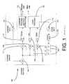
- FIG. 1shows a typical conventional GNSS receiver correlation channel that is used to track one satellite signal (either a data signal or a pilot signal).
- satellite signaleither a data signal or a pilot signal
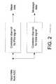
- FIG. 2shows how two such channels can be used to use both pilot and data signals from one satellite, thus duplicating the hardware size needed for each satellite.
- a correlator channel for the pilot signalis used for measurement data
- a correlator channel for the data signalis used for message data.
- “Measurement data”refers to the measurement data that the receiver generates regarding the signal timing. This data is used in the position and velocity computation process in the receiver. This data typically includes code phase information, carrier phase information, and code and carrier frequency information.
- the C/A code and the P/Y codeare such different and require so different processing rates that using a common processing channel to achieve the reception of both signals is not cost-effective.
- the present inventionprovides for a system and method for efficiently reducing the hardware complexity required for enabling the reception of both a pilot signal and a data signal in a GNSS receiver.
- information from the pilot signalis used to track both signals from the satellite such that only the demodulation of the data signal is necessary for efficient operation.
- a second embodiment of the inventioninvolves the implementation of only one hardware channel to alternately track both the pilot signal and the data signal. In this situation, for satellite acquisition, the pilot signal is used, and for high signal-to-noise ratio tracking, the data signal is used. The pilot signal is used for low signal-to-noise ratio tracking.
- the system and method of the present inventionprovides a solution for enabling a receiver to receive both pilot and carrier signals from a GNSS satellite with minimal hardware.
- information from the pilot signalis used to track both signals from the satellite
- a single hardware channelalternately tracks both the pilot signal and the data signal
- there is no hardware size increase at all over receivers capable of only using the data signalalthough some performance is sacrificed compared to receivers that receive both signals simultaneously. However, this performance is still substantially better than with those receivers that only track the data signal. Tracking only either the pilot or data signal simplifies the software. Using less hardware also decreases the power consumption of the receiver.
- FIG. 1is a representation of a conventional GNSS receiver correlation channel that is used to track a single satellite channel;
- FIG. 2is a representation showing how two receiver correlation channels can be used to receive both pilot signals and data signals from a satellite;
- FIG. 3is a representation of an optimized receiver architecture including an optimized pilot and data signal tracking channel according to one embodiment of the invention
- FIG. 4is a representation of a dynamic pilot and data signal switching system according to another embodiment of the present invention.
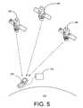
- FIG. 5is a representation showing a generic receiver and satellite system within which the present invention may be implemented.
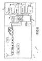
- FIG. 6is a schematic representation of a positioning receiver constructed according to one embodiment of the present invention.
- FIG. 5shows a generic representation of a system within which the present invention operates.
- a receiver 500is located at a particular location on the Earth 510 at a given moment, and a plurality of satellites 520 orbit the Earth 510 .
- Each of the satellites 520is capable of transmitting information to the receiver 500 , which can receive a number of the signals, possibly with the help of an assistance mechanism 530 .
- the circuitry for a typical receiver according to one embodiment of the present inventionis shown in FIG. 6 in a simplified block diagram.
- the electronic device 1 of FIG. 6comprises, for example, a positioning receiver 2 as well as communication mechanism 3 such as an antenna. By this communication mechanism 3 , the electronic device 1 may, if necessary, communicate with a communication network such as a mobile communication network.
- the electronic device 1comprises a control block 5 which may comprises a processor MCU and/or a digital signal processor DSP.
- the electronic device 1is provided with at least one user interface 6 , comprising a display 7 , a keypad 8 and audio system components 9 a, 9 b, 9 c in one embodiment of the invention.
- the electronic device 1For storing data and application software, the electronic device 1 is provided with a memory unit 10 .
- Individual circuits and elementsare all of a type well known in the art, for example in the Nokia range of mobile telephones.
- the receiver 500 of the present inventioncan be incorporated into devices such as a mobile telephone.
- the present inventioncan also be incorporated into a variety of other devices.
- FIG. 1is a representation of a conventional GNSS receiver correlation channel 100 that is used to track a single satellite channel.
- Input data from an analog-to-digital converter(not shown) is input to the correlation channel 100 .
- This datais subject to an initial multiplier 105 , as well as an early multiplier 107 , a late multiplier 109 and a prompt multiplier 111 .
- the datais subject to a corresponding early integrate-dump block 113 , late integrate-dump block 115 and prompt integrate-dump block 117 , respectively.
- Each pair of multipliers and integrate-dump blockswork to correlate the signal, which is then transmitted for subsequent carrier tracking and data extraction 110 and code tracking 120 .
- Both the carrier tracking and data extraction 110 and the code tracking 120typically are performed in the software of the receiver 500 .
- the carrier tracking and data extraction 110ultimately produces message data for use, while the combination of the carrier tracking and data extraction 110 and the code tracking 120 produces measurement data for use.
- the correlation channel 100also includes a carrier numerically controlled oscillator (NCO) 130 , as well as a code NCO 140 .
- the code NCO 140generates the code rate clock signal for a code generator 150 .
- the code from the code generator 150is then fed to a delay line composed of a plurality of delay elements 160 , which construct early, late and prompt versions of the generated code for subsequent correlation.
- FIG. 3shows an optimized and combined receiver correlation channel architecture 300 that can be used for the simultaneous reception of data.
- the optimized receiver correlation channel architecture 300one complete correlation channel 310 has been implemented.
- This correlation channel 310is similar to the correlation channel 100 depicted in FIG. 1 .
- the correlation channel 310is used to track the pilot signal.
- a pilot code generator 315is used to generate pilot data code based upon the code rate clock signal received from the code NCO 140 .
- the optimized receiver architecture 300 of FIG. 3includes a data signal replica code generator 320 .
- the codeis removed or wiped off from the received signal by multiplying the incoming signal with correctly aligned locally generated replica code.
- a data signal multiplier 325 and a data integrate-dump block 335are used to form the code-correlated data signal.
- Block 330performs demodulation, symbol and frame synchronization on the code-correlated data signal in order to recover the message data 340 transmitted by the satellite 520 whose signal is being received.
- the data signal replica code generator 320can be controlled by the associated pilot signal tracking loop 350 , because the signals are generated at the satellite 520 using a single frequency reference, and the carrier frequency of both signals is the same (leading to identical atmospheric delays).
- pilot and data signalsTwo replicas of the carriers would also be generated. These carriers can be generated using the same concept as is used for the replica code.
- information from the pilot signalis used to track both the pilot signal and the data signal from the respective satellites 520 . In this system, only the demodulation of the data signal is necessary, and the hardware for tracking the data signal is not necessary.
- FIG. 4A second embodiment of the present invention is depicted in FIG. 4 .
- the architecture 400 of FIG. 4like the embodiment shown in FIG. 3 , includes a separate data signal replica code generator 320 and pilot code generator 315 with a correlation channel which is otherwise substantially identical to the correlation channel of FIG. 1 . In the embodiment shown in FIG. 4 , however, no separate correlator for the data signal is necessary.
- a software controllable switch 430selects between the pilot and data codes. It should also be noted that the separate data signal replica code generator and pilot code generator 320 and 315 and the software controllable switch 430 can be built into a single configurable code generator. Again, if slightly different carrier frequencies are utilized, two switchable carrier replica generators are also required. The tracking software observes the signal level during tracking.
- the receiver 500When the receiver 500 begins to search for the satellite signal, there is no need for the data signal receiving parts, as the pilot signal has been designed for superior acquisition performance. With low signal to noise ratios, the data message cannot be received, since the reception requires a certain signal-to-noise ratio (SNR) which is higher than the SNR threshold for tracking. Again, the data signal reception capability is not needed at all. Low SNRs are increasingly common for normal GNSS operation due to requirements for indoor and urban canyon conditions. In many instances, the GNSS receiver 500 can also obtain the satellite data message through more robust communication channels as an assistance mechanism 530 , which also makes the need for receiving the data signal unnecessary. However, if the receiver 500 needs to operate in stand-alone mode within “normal” conditions, i.e.
- the signal levelis relatively high, the data signal needs to be received to allow the receiver 500 to produce location information to the user.
- using the data signal for tracking after acquisitioncan provide almost as good measurements as using the pilot signal; therefore the pilot signal is not needed in such cases.
- the present inventionis described in the general context of method steps, which may be implemented in one embodiment by a program product including computer-executable instructions, such as program code, executed by computers in networked environments.
- program modulesinclude routines, programs, objects, components, data structures, etc. that perform particular tasks or implement particular abstract data types.
- Computer-executable instructions, associated data structures, and program modulesrepresent examples of program code for executing steps of the methods disclosed herein. The particular sequence of such executable instructions or associated data structures represent examples of corresponding acts for implementing the functions described in such steps.
Landscapes
- Engineering & Computer Science (AREA)
- Radar, Positioning & Navigation (AREA)
- Remote Sensing (AREA)
- Computer Networks & Wireless Communication (AREA)
- Physics & Mathematics (AREA)
- General Physics & Mathematics (AREA)
- Signal Processing (AREA)
- Position Fixing By Use Of Radio Waves (AREA)
Abstract
Description
Claims (11)
Priority Applications (4)
| Application Number | Priority Date | Filing Date | Title |
|---|---|---|---|
| US11/170,876US7706431B2 (en) | 2005-06-30 | 2005-06-30 | System and method for providing optimized receiver architectures for combined pilot and data signal tracking |
| PCT/IB2006/001793WO2007004017A1 (en) | 2005-06-30 | 2006-06-28 | System and method for providing optimized receiver architectures for combined pilot and data signal tracking |
| EP06795060AEP1896867A4 (en) | 2005-06-30 | 2006-06-28 | SYSTEM AND METHOD FOR PROVIDING OPTIMIZED RECEIVER ARCHITECTURES FOR COMBINED PURSUIT OF DATA SIGNALS AND PILOT SIGNALS |
| CN200680023887.XACN101213471B (en) | 2005-06-30 | 2006-06-28 | System and method for providing optimized receiver architectures for combined pilot and data signal tracking |
Applications Claiming Priority (1)
| Application Number | Priority Date | Filing Date | Title |
|---|---|---|---|
| US11/170,876US7706431B2 (en) | 2005-06-30 | 2005-06-30 | System and method for providing optimized receiver architectures for combined pilot and data signal tracking |
Publications (2)
| Publication Number | Publication Date |
|---|---|
| US20070009014A1 US20070009014A1 (en) | 2007-01-11 |
| US7706431B2true US7706431B2 (en) | 2010-04-27 |
Family
ID=37604123
Family Applications (1)
| Application Number | Title | Priority Date | Filing Date |
|---|---|---|---|
| US11/170,876Expired - Fee RelatedUS7706431B2 (en) | 2005-06-30 | 2005-06-30 | System and method for providing optimized receiver architectures for combined pilot and data signal tracking |
Country Status (4)
| Country | Link |
|---|---|
| US (1) | US7706431B2 (en) |
| EP (1) | EP1896867A4 (en) |
| CN (1) | CN101213471B (en) |
| WO (1) | WO2007004017A1 (en) |
Cited By (2)
| Publication number | Priority date | Publication date | Assignee | Title |
|---|---|---|---|---|
| US20110159835A1 (en)* | 2009-12-30 | 2011-06-30 | Quintic Holdings | Crystal-less clock generation for radio frequency receivers |
| US11009609B2 (en) | 2018-07-17 | 2021-05-18 | Spire Global, Inc. | Systems and methods for de-noising GNSS signals |
Families Citing this family (6)
| Publication number | Priority date | Publication date | Assignee | Title |
|---|---|---|---|---|
| PL190092B1 (en)* | 1997-04-16 | 2005-10-31 | Amgen Inc | Osteoprotegeric bonding proteins and receptors |
| US8594244B2 (en)* | 2009-04-06 | 2013-11-26 | Mediatek Inc. | Data signal phase reversal correction method and system implementing the same |
| FR2982033B1 (en)* | 2011-10-26 | 2013-12-27 | Thales Sa | METHOD FOR COORDINATED PROCESSING OF SIGNALS ISSUED BY BEACONS |
| US9100107B1 (en)* | 2014-10-22 | 2015-08-04 | Honeywell International Inc. | Systems and methods for global navigation satellite system signal tracking |
| CN104614740B (en) | 2015-02-10 | 2016-08-17 | 华中科技大学 | A kind of navigation signal data pilot combined tracking method and device |
| CN105204043B (en)* | 2015-09-15 | 2018-02-13 | 武汉导航与位置服务工业技术研究院有限责任公司 | Signal acceptance method and device |
Citations (14)
| Publication number | Priority date | Publication date | Assignee | Title |
|---|---|---|---|---|
| US5493588A (en)* | 1992-01-22 | 1996-02-20 | Trimble Navigation Limited | Multipath compensation for code phase signals |
| EP0880713A1 (en) | 1995-10-09 | 1998-12-02 | Snaptrack, Inc. | Combined gps positioning system and communications system utilizing shared circuitry |
| WO1999031817A1 (en) | 1997-12-12 | 1999-06-24 | Thomson Consumer Electronics, Inc. | Receiver with parallel correlator for spread spectrum digital transmission |
| GB2351864A (en) | 1999-07-05 | 2001-01-10 | Symmetricom Inc | RF receiver for pseudo-random encoded signals in a satellite ranging system. |
| US6239743B1 (en)* | 1999-07-28 | 2001-05-29 | Trimble Navigation Limited | Integrated split spectrum positioning system receiver |
| US6282231B1 (en)* | 1999-12-14 | 2001-08-28 | Sirf Technology, Inc. | Strong signal cancellation to enhance processing of weak spread spectrum signal |
| US6317454B1 (en)* | 1997-11-19 | 2001-11-13 | Matsushita Electric Industrial Co., Ltd. | Rake receiver, and mobile unit and base station for portable telephone system and using the same |
| US6763058B1 (en)* | 2000-06-27 | 2004-07-13 | Northrop Grumman Corporation | Low signal to noise ratio acquisition and link characterization techniques for VSAT spread spectrum modems |
| WO2005006012A1 (en) | 2003-06-13 | 2005-01-20 | Centre National D'etudes Spatiales | Method and device for the demodulation of satellite radio navigation signals |
| US20050012664A1 (en) | 2003-07-14 | 2005-01-20 | Neil Gerein | Hardware architecture for processing galileo alternate binary offset carrier (altboc) signals |
| US6868110B2 (en)* | 1999-12-01 | 2005-03-15 | The Board Of Trustees Of The Leland Stanford Junior University | Multipath and tracking error reduction method for spread-spectrum receivers |
| US6873288B2 (en)* | 2000-06-14 | 2005-03-29 | Stephen B. Heppe | Enhanced GNSS receiver |
| US20060274821A1 (en)* | 2005-06-01 | 2006-12-07 | Mediatek Incorporation | Bit synchronization detection methods and systems |
| US7463979B2 (en)* | 2003-08-28 | 2008-12-09 | Motorola, Inc. | Method and apparatus for initializing an approximate position in a GPS receiver |
Family Cites Families (2)
| Publication number | Priority date | Publication date | Assignee | Title |
|---|---|---|---|---|
| US5506864A (en)* | 1990-12-05 | 1996-04-09 | Interdigital Technology Corporation | CDMA communications and geolocation system and method |
| US6424678B1 (en)* | 2000-08-01 | 2002-07-23 | Motorola, Inc. | Scalable pattern methodology for multi-carrier communication systems |
- 2005
- 2005-06-30USUS11/170,876patent/US7706431B2/ennot_activeExpired - Fee Related
- 2006
- 2006-06-28CNCN200680023887.XApatent/CN101213471B/ennot_activeExpired - Fee Related
- 2006-06-28WOPCT/IB2006/001793patent/WO2007004017A1/enactiveApplication Filing
- 2006-06-28EPEP06795060Apatent/EP1896867A4/ennot_activeWithdrawn
Patent Citations (14)
| Publication number | Priority date | Publication date | Assignee | Title |
|---|---|---|---|---|
| US5493588A (en)* | 1992-01-22 | 1996-02-20 | Trimble Navigation Limited | Multipath compensation for code phase signals |
| EP0880713A1 (en) | 1995-10-09 | 1998-12-02 | Snaptrack, Inc. | Combined gps positioning system and communications system utilizing shared circuitry |
| US6317454B1 (en)* | 1997-11-19 | 2001-11-13 | Matsushita Electric Industrial Co., Ltd. | Rake receiver, and mobile unit and base station for portable telephone system and using the same |
| WO1999031817A1 (en) | 1997-12-12 | 1999-06-24 | Thomson Consumer Electronics, Inc. | Receiver with parallel correlator for spread spectrum digital transmission |
| GB2351864A (en) | 1999-07-05 | 2001-01-10 | Symmetricom Inc | RF receiver for pseudo-random encoded signals in a satellite ranging system. |
| US6239743B1 (en)* | 1999-07-28 | 2001-05-29 | Trimble Navigation Limited | Integrated split spectrum positioning system receiver |
| US6868110B2 (en)* | 1999-12-01 | 2005-03-15 | The Board Of Trustees Of The Leland Stanford Junior University | Multipath and tracking error reduction method for spread-spectrum receivers |
| US6282231B1 (en)* | 1999-12-14 | 2001-08-28 | Sirf Technology, Inc. | Strong signal cancellation to enhance processing of weak spread spectrum signal |
| US6873288B2 (en)* | 2000-06-14 | 2005-03-29 | Stephen B. Heppe | Enhanced GNSS receiver |
| US6763058B1 (en)* | 2000-06-27 | 2004-07-13 | Northrop Grumman Corporation | Low signal to noise ratio acquisition and link characterization techniques for VSAT spread spectrum modems |
| WO2005006012A1 (en) | 2003-06-13 | 2005-01-20 | Centre National D'etudes Spatiales | Method and device for the demodulation of satellite radio navigation signals |
| US20050012664A1 (en) | 2003-07-14 | 2005-01-20 | Neil Gerein | Hardware architecture for processing galileo alternate binary offset carrier (altboc) signals |
| US7463979B2 (en)* | 2003-08-28 | 2008-12-09 | Motorola, Inc. | Method and apparatus for initializing an approximate position in a GPS receiver |
| US20060274821A1 (en)* | 2005-06-01 | 2006-12-07 | Mediatek Incorporation | Bit synchronization detection methods and systems |
Non-Patent Citations (14)
| Title |
|---|
| All-Digital GPS Receiver Mechanization, Peter C. Ould and Robert J. Van Wechel, Navigation: Journal of the Institute of Navigation, vol. 28, No. 3, Fall 1981, U.S.A., pp. 178-188. |
| GPS Dictionary A-G, www.datatraxus.com, Datatrax LLC, Apr. 19, 2005, pp. 1-12. |
| GPS Dictionary H-O, www.datatraxus.com, Datatrax LLC, Apr. 19, 2005, pp. 1-7. |
| GPS Dictionary P-U, www.datatraxus.com, Datatrax LLC, Apr. 19, 2005, pp. 1-8. |
| GPS Dictionary V-Z, www.datatraxus.com, Datatrax LLC, Apr. 19, 2005, pp. 1-8. |
| GPS Signal Structure and Performance Characteristics, J.J. Spilker, Jr., Navigation: Journal of the Institute of Navigation, vol. 25, No. 2, Summer 1978, U.S.A., pp. 121-148. |
| How GPS Receivers Work, Howstuffworks "How GPS Receivers Work", 2-D Trilateration, http://electronics.howstuffworks.com, Apr. 19, 2005, pp. 1-3. |
| How GPS Receivers Work, Howstuffworks "How GPS Receivers Work", Differential GPS, http://electronics.howstuffworks.com, Apr. 19, 2005, pp. 1-2. |
| How GPS Receivers Work, Howstuffworks "How GPS Receivers Work", http://electronics.howstuffworks.com, Apr. 19, 2005, pp. 1-2. |
| How GPS Receivers Work, Howstuffworks "How GPS Receivers Work", Trilateration Basics, http://electronics.howstuffworks.com, Apr. 19, 2005, pp. 1-3. |
| How GPS Receivers Work, Howstuffworks "How GPS Receivers Work", Using the Data http://electronics.howstuffworks.com, Apr. 19, 2005, pp. 1-3. |
| International Search Report for Application PCT/IB2006/001793. |
| Theory of Spread-Spectrum Communications-A Tutorial, Raymond L. Pickholtz and Donald L. Schilling, and Laurence B. Milstein, IEE Transactions on Communications, vol. Com-30, No. 5, May 1982, pp. 855-884. |
| Theory of Spread-Spectrum Communications—A Tutorial, Raymond L. Pickholtz and Donald L. Schilling, and Laurence B. Milstein, IEE Transactions on Communications, vol. Com-30, No. 5, May 1982, pp. 855-884. |
Cited By (4)
| Publication number | Priority date | Publication date | Assignee | Title |
|---|---|---|---|---|
| US20110159835A1 (en)* | 2009-12-30 | 2011-06-30 | Quintic Holdings | Crystal-less clock generation for radio frequency receivers |
| US8280330B2 (en)* | 2009-12-30 | 2012-10-02 | Quintic Holdings | Crystal-less clock generation for radio frequency receivers |
| US11009609B2 (en) | 2018-07-17 | 2021-05-18 | Spire Global, Inc. | Systems and methods for de-noising GNSS signals |
| US11585946B2 (en) | 2018-07-17 | 2023-02-21 | Spire Global Subsidiary, Inc. | Systems and methods for de-noising GNSS signals |
Also Published As
| Publication number | Publication date |
|---|---|
| WO2007004017A1 (en) | 2007-01-11 |
| EP1896867A4 (en) | 2013-03-27 |
| CN101213471B (en) | 2011-12-21 |
| EP1896867A1 (en) | 2008-03-12 |
| CN101213471A (en) | 2008-07-02 |
| US20070009014A1 (en) | 2007-01-11 |
Similar Documents
| Publication | Publication Date | Title |
|---|---|---|
| KR101164749B1 (en) | Gnns receiver and signal tracking circuit and system | |
| US8989326B2 (en) | Method and apparatus for software GPS receiver | |
| US8369464B2 (en) | System and method for acquisition of signals | |
| US8351486B2 (en) | Parallel correlator implementation using hybrid correlation in spread-spectrum communication | |
| EP1896867A1 (en) | System and method for providing optimized receiver architectures for combined pilot and data signal tracking | |
| JP2011504229A5 (en) | ||
| US11598883B2 (en) | Memory optimized GNSS correlator | |
| US20200064492A1 (en) | Gnss receiver apparatus with gnss pseudo random noise delayed sequence generator | |
| US6016121A (en) | Multiple frequency GPS receive operation using single frequency sequencing | |
| JP2003101422A (en) | Radiofrequency signal receiver provided with means for correcting effect of multipath signal, and method for activating the same | |
| JP4095823B2 (en) | Radio frequency signal receiver having means for improving signal reception dynamics | |
| US8362952B2 (en) | Memory reduction in GNSS receiver | |
| US7526014B2 (en) | Correlator for spread spectrum receiver | |
| CN1947030B (en) | Positioning receiver | |
| US7839915B2 (en) | Reception of a spread spectrum modulated signal | |
| WO2009044205A2 (en) | Correlator for global navigation satellite systems | |
| EP4575581A1 (en) | Method for aiding acquisition of a satellite signal and satellite receiver device | |
| JP2007124291A (en) | Positioning device and control method thereof | |
| EP1724600B1 (en) | A system and method for acquisition of signals | |
| US20090304050A1 (en) | Method in a CDMA Receiver Using Hardware and Software in Acquisition, Tracking and Hosting | |
| HK1051573B (en) | Radio frequency signal receiver with means for correcting the radiofrequency signal receiver with means for correcting the effects of multipath signals, and method for activating the receiver |
Legal Events
| Date | Code | Title | Description |
|---|---|---|---|
| AS | Assignment | Owner name:NOKIA CORPORATION,FINLAND Free format text:ASSIGNMENT OF ASSIGNORS INTEREST;ASSIGNORS:EEROLA, VILLE;PIETILA, SAMULI;VALIO, HARI;REEL/FRAME:016992/0071 Effective date:20050823 Owner name:NOKIA CORPORATION, FINLAND Free format text:ASSIGNMENT OF ASSIGNORS INTEREST;ASSIGNORS:EEROLA, VILLE;PIETILA, SAMULI;VALIO, HARI;REEL/FRAME:016992/0071 Effective date:20050823 | |
| AS | Assignment | Owner name:RPX CORPORATION, CALIFORNIA Free format text:ASSIGNMENT OF ASSIGNORS INTEREST;ASSIGNOR:NOKIA CORPORATION;REEL/FRAME:028323/0196 Effective date:20120531 | |
| FEPP | Fee payment procedure | Free format text:PAYOR NUMBER ASSIGNED (ORIGINAL EVENT CODE: ASPN); ENTITY STATUS OF PATENT OWNER: LARGE ENTITY Free format text:PAYER NUMBER DE-ASSIGNED (ORIGINAL EVENT CODE: RMPN); ENTITY STATUS OF PATENT OWNER: LARGE ENTITY | |
| FPAY | Fee payment | Year of fee payment:4 | |
| FEPP | Fee payment procedure | Free format text:MAINTENANCE FEE REMINDER MAILED (ORIGINAL EVENT CODE: REM.) | |
| LAPS | Lapse for failure to pay maintenance fees | Free format text:PATENT EXPIRED FOR FAILURE TO PAY MAINTENANCE FEES (ORIGINAL EVENT CODE: EXP.) | |
| STCH | Information on status: patent discontinuation | Free format text:PATENT EXPIRED DUE TO NONPAYMENT OF MAINTENANCE FEES UNDER 37 CFR 1.362 | |
| FP | Lapsed due to failure to pay maintenance fee | Effective date:20180427 | |
| AS | Assignment | Owner name:JEFFERIES FINANCE LLC, NEW YORK Free format text:SECURITY INTEREST;ASSIGNOR:RPX CORPORATION;REEL/FRAME:046486/0433 Effective date:20180619 | |
| AS | Assignment | Owner name:RPX CORPORATION, CALIFORNIA Free format text:RELEASE BY SECURED PARTY;ASSIGNOR:JEFFERIES FINANCE LLC;REEL/FRAME:054486/0422 Effective date:20201023 |