US7706320B2 - Mesh based/tower based network - Google Patents
Mesh based/tower based networkDownload PDFInfo
- Publication number
- US7706320B2 US7706320B2US11/588,715US58871506AUS7706320B2US 7706320 B2US7706320 B2US 7706320B2US 58871506 AUS58871506 AUS 58871506AUS 7706320 B2US7706320 B2US 7706320B2
- Authority
- US
- United States
- Prior art keywords
- communications
- communication
- elevated
- node
- devices
- Prior art date
- Legal status (The legal status is an assumption and is not a legal conclusion. Google has not performed a legal analysis and makes no representation as to the accuracy of the status listed.)
- Active, expires
Links
- 238000004891communicationMethods0.000claimsabstractdescription267
- 238000000034methodMethods0.000claimsdescription18
- 230000005540biological transmissionEffects0.000claimsdescription17
- 230000004044responseEffects0.000claimsdescription6
- 230000000694effectsEffects0.000description9
- 238000010586diagramMethods0.000description6
- 238000005562fadingMethods0.000description6
- 230000006872improvementEffects0.000description6
- 238000001228spectrumMethods0.000description5
- 235000008694Humulus lupulusNutrition0.000description3
- 230000002411adverseEffects0.000description3
- 238000013480data collectionMethods0.000description3
- 238000013459approachMethods0.000description2
- 238000004364calculation methodMethods0.000description2
- 230000000977initiatory effectEffects0.000description2
- 238000005259measurementMethods0.000description2
- 230000035945sensitivityEffects0.000description2
- 230000001360synchronised effectEffects0.000description2
- 238000012360testing methodMethods0.000description2
- 230000003044adaptive effectEffects0.000description1
- 230000002730additional effectEffects0.000description1
- 230000003466anti-cipated effectEffects0.000description1
- 230000001413cellular effectEffects0.000description1
- 230000003111delayed effectEffects0.000description1
- 238000005516engineering processMethods0.000description1
- 230000002349favourable effectEffects0.000description1
- 230000035515penetrationEffects0.000description1
- 230000008569processEffects0.000description1
- 230000009467reductionEffects0.000description1
- 230000001105regulatory effectEffects0.000description1
- 229920006395saturated elastomerPolymers0.000description1
Images


Classifications
- H—ELECTRICITY
- H04—ELECTRIC COMMUNICATION TECHNIQUE
- H04W—WIRELESS COMMUNICATION NETWORKS
- H04W40/00—Communication routing or communication path finding
- H04W40/02—Communication route or path selection, e.g. power-based or shortest path routing
- H04W40/12—Communication route or path selection, e.g. power-based or shortest path routing based on transmission quality or channel quality
- H04W40/16—Communication route or path selection, e.g. power-based or shortest path routing based on transmission quality or channel quality based on interference
- H—ELECTRICITY
- H04—ELECTRIC COMMUNICATION TECHNIQUE
- H04W—WIRELESS COMMUNICATION NETWORKS
- H04W40/00—Communication routing or communication path finding
- H04W40/02—Communication route or path selection, e.g. power-based or shortest path routing
- H04W40/20—Communication route or path selection, e.g. power-based or shortest path routing based on geographic position or location
Definitions
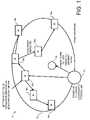
- FIG. 1is a block diagram illustrating an exemplary embodiment of a network configuration for communicating data between a communications device and a communications point.
- FIG. 2is a diagram illustrating exemplary ranges for communication between a communications device and a communications point from FIG. 1 .
- FIG. 3is a diagram illustrating an exemplary embodiment of a plurality of communications points, similar to the communications points from FIG. 1 .
- FIG. 4is an exemplary graphical representation, illustrating reception characteristics that may be achieved through use of a network configuration, such as the network configuration from FIG. 1 .
- FIG. 5is an exemplary graphical representation of performance related to locales that may be achieved in a network, such as the network configuration from FIG. 1 .
- FIG. 6is an exemplary embodiment of a communications point, illustrating a ratio based on propagation formulae, similar to the communications point from FIG. 1 .
- Described in this disclosureare embodiments that include features, functionality, and advantages of a mesh based network, including but not limited to multiple communication routes and frequency hopping. Additionally included are embodiments for gaining a decibel link budget by combining mesh based communication on sub-layers with a first order point to multipoint link where the collection device is situated at an elevated location above local clutter to enhance range. In such configurations, range may be further enhanced through sub-layer mesh operation.
- FIG. 1is a block diagram illustrating an exemplary embodiment of a network configuration for communicating data between a communications device and a communications point.
- network 2may be configured to select particular Layer 1 communication devices 14 , 16 (e.g., meter points) by a higher than mesh-based Received Signal Strength Indication (RSSI) measurement threshold. This may include selecting a small proportion of the total communications devices 14 , 16 that may communicate with the elevated communications point 10 .
- RSSIReceived Signal Strength Indication
- Such a configurationmay result in a high degree of integrity in the Layer 1 links to enhance range, traffic handling, and interference protection. Additionally, merely raising the height of the communications point 10 (e.g., intelligent node data collector) may enhance raw range.
- RSSIReceived Signal Strength Indication
- the communications devices 16 in Layer 1may be selected based on an RSSI value, as interference protection to about 5% of the communications devices 14 , 16 approaches the coverage area 12 . This may assist in defining Layer 1 . Additionally, the minimum RSSI value may be such that connectivity is configured to receive 80% of the transmissions from the total communications devices 14 , 16 served (mesh and Layer 1 combined).
- An elevated communications point 10may include positioning the communications point 10 at a location above local obstructions where standard propagation macro models apply. By selecting a desired communicating multipoint and routing a substantial number of less well communicating points through this optimal multipoint communications devices 16 , losses may be reduced.
- communications datamay be routed via a mesh network.
- the optimal Layer 1 communications devices 14 , 16may be selected on the basis of best RSSI signal strength with the elevated central data collection position.
- a COST settingmay be treated as being similar to a squelch, where signals below a certain threshold may be rejected at the communications point 10 .
- the COST setting to receive the 5% of optimally disposed Layer 1 communications devices 14 , 16may be higher than the COST setting for receiving 50% of Layer 1 communications devices 14 , 16 . Depending on the particular embodiment this difference may be around 10 to 20 dB. This may enable better interference rejection for the elevated communications point 10 .
- the COSTcould be set as high as ⁇ 80 dBm or even ⁇ 60 dBm instead of the ⁇ 100 dBm that might be used for a utility pole top device receiver.
- the Layer 1 meter point end receivermay have a lower probability of extreme interference levels and may therefore use a lower COST.
- communications point 10may be configured to define coverage area 12 .
- Communications point 10may include a tower and/or may be configured at an elevated location for a testing link.
- Communications point 10may determine one or more communications devices 16 for initiating communications. More specifically, in at least one nonlimiting example, communications point 10 may be configured to determine whether communications device 16 a is suited for facilitating communications with other communications devices 14 , 16 . This determination may be made based on relative location of communications device 16 a and/or other factors, such as the capabilities of communications device 16 a.
- communications point 10may send data to other communications devices via communications device 16 a .
- datamay be sent to communications device 16 b and communications device 16 c via communications device 16 a .
- datamay be sent to communications device 14 a via communications device 16 b .
- datamay be sent to communications device 14 b via 16 c .
- Datamay be sent to communications device 16 d via communications device 16 c and to communications device 14 c via communications device 16 d.
- communications point 10may be configured with logic for determining a facilitator communications device 16 for facilitating data communications to other communications devices 14 , 16 . More specifically, in at least one nonlimiting example, communications point 10 may be configured to determine that data sent to communications device 14 c is sent to communications devices 16 a , 16 c , 16 d , and then to communications device 14 c.
- communications devices 14 , 16include logic for determining a facilitator communications device 16 for the next transmission. More specifically, in at least one nonlimiting example, communications point 10 may be configured to send data to communications device 16 a . Communications point may determine that a communications device 16 a may be utilized for sending data to other communications devices 14 , 16 . The communications point 10 may then send data associated with a plurality of communications devices (e.g., communications devices 14 a , 14 b , and 14 c ) to communications device 16 a.
- a plurality of communications devicese.g., communications devices 14 a , 14 b , and 14 c
- communications device 16 amay determine that the data associated with communications device 14 a may be sent to communications device 14 a via communications device 16 b .
- communications device 16 bmay determine that the data may be sent directly to communications device 14 a.
- communications point 10may be configured to determine a potential routing scheme.
- communications devices 14 , 16may be configured to amend the routing scheme. As a nonlimiting example, if one or more of the communications devices 14 , 16 in the routing scheme leave coverage area 12 , the routing scheme may be amended such that the data can be efficiently communicated to the desired termination point.
- FIG. 2is a diagram illustrating exemplary ranges for communication between a communications device and a communications point from FIG. 1 .
- communications point 10may be coupled to Layer 1 via a meter link.
- the COSTmay be set to select the top 5% of all communications devices 14 , 16 as Layer 1 meters in the outermost annulus (see 22 a , 22 b , FIG. 3 ) of the coverage area. In at least one exemplary embodiment, this may range from 1 to 10 miles, depending on actual level of interference and whether the cell area is in a predominantly urban, suburban or rural scenario.
- the exemplary embodiment of FIG. 2illustrates that communications device 14 , 16 is currently positioned 5 feet above ground, which is merely a nonlimiting example.
- FIG. 3is a diagram illustrating an exemplary embodiment of a plurality of communications points, similar to the communications points from FIG. 1 .
- communications point 10 amay create a coverage area 12 a .
- Coverage area 12 amay have annuli 22 a , 24 a .
- communications point 10 bmay create a coverage area 12 b , as defined by annuli 22 b , 24 b.
- the COST for the elevated communications point 10 amay be set dynamically on an occasional update to reflect changing propagation and interference patterns to the highest threshold consistent with bringing in the Layer 1 communication device 14 , 16 . This may facilitate the highest interference protection for the specific channel in question.
- the elevated communications point 10 aadditionally may occasionally test the link against the interference sensed by the communications point 10 .
- the communications point 10 amay ping this link. Pinging the link in such a scenario may be practical because the link may be unbalanced in favor of the downlink (normally lower COST setting). If the communications point 10 a determines the interference is too high to consistently receive a ping response from communications device 14 , 16 , a procedure for a handoff to a neighboring cell 12 b may be initiated.
- the elevated communications point 10may check interference on each channel and adjust a COST for each channel.
- the communications point 10may instruct those Layer 1 communications devices 14 , 16 to transmit the missing uplink information on the remaining channels that are available. This may result in a reduced, but reliable, stream of traffic from the marginal Layer 1 communications devices 14 , 16 to the elevated location.
- Significantly locked out channelsmay become another criterion for determining hand off to a neighboring cell.
- the antennas in a cell phone systemmay be sectionized to give a 3 cell repeat pattern on each 120 degrees of azimuth view from the communications point 10 .
- Embodiments of this disclosuremay be configured to utilize an OMNI and/or COLINEAR communications point 10 , where stable mounting near the top and/or on a suitably light antenna structure is available. Sectionized antennas as groups of 3 or greater may be used in cases where the elevation structure may be a building or heavy mast structure. Use of such a configuration in the Industrial, Scientific, and Medical (ISM) band may be configured to respect the regulations for having an upper antenna gain limit of 6 dBi where a full Watt of power may be available as a drive for the antenna.
- ISMIndustrial, Scientific, and Medical
- sectored antennasare employed, their use may not only increase capacity, but may also increase the ability for azimuth interference rejection.
- a similar techniquemay be employed on one or more channels and each sectored antenna within that channel. This may provide further interference protection at the elevated site that might prevent hand off of marginal meters to another communications point 10 .
- embodiments of this disclosuremay be configured with specified layers from communications devices 14 , 16 , through repeaters 18 to a final layer of a selected (Layer 1 ) repeater 18 , where the final Layer 1 is not constrained by the relatively unknown propagation criteria of sub-rooftop to sub-rooftop radio communication. While some mesh networks may be constrained to reliable operating ranges of a few thousand feet for each relay link, because of the asymptotic increase in Radio Frequency (RF) penetration loss involved with radiating RF signals through heavy clutter loss (e.g., adverse terrain, buildings, and foliage), others may not be so limited.
- RFRadio Frequency
- some point to multipoint systems where one or both ends of the links are elevatedmay be configured as either quasi line of site (LOS) links or traverse a set amount of clutter loss at the low (or mobile) end of the link.
- LOSline of site
- These configurationsmay obey propagation models that are quantified in the mobile radio and cell-phone industry field.
- a model, among others, that may be used for embodiments disclosed hereinis the Okumura Hata model, which may be applied down to a minimum mast height of 90 feet.
- embodiments disclosed hereinmay have a several mile range, rather than a range of 100-1000 feet. Additionally, coverage requirements for television broadcast transmitters are generally 50%. Coverage requirements for a mobile system may generally be around 95%. Thus, mobile systems may demand a further fade factor equal to 1.9*Sigma, where Sigma is the dB mean variance of a radio fading distribution as defined by a normal or log normal distribution (a Log Normal distribution is a normal distribution where the abscissa is a dB or logarithmic term).
- Sigmaequates to 5.5 dB. So about 9 dB greater margin may be allowed for mobile radio coverage than standard television coverage. This is because mobile units may be configured to move through fades without a loss or drop out of the communications link.
- a television receivercan have an associated antenna moved to a higher location or a more favorable location to gain good reception.
- AMRAutomated Meter Reading
- AMRAutomated Meter Reading
- the individual communications device 14 , 16may be configured to send and receive data in real time and the scope for resending the transmission by an Automatic Repeat Request (ARQ) technique is limited both in scope and in the timing available within the restricted bandwidth. Therefore, a predetermined mobile fading factor may be desired. This situation is further exacerbated by the presence of Raleigh distributed fast fades, in addition to the substantively time invariant lognormal fades.
- ARQAutomatic Repeat Request
- the use of a mesh configurationmay be utilized as a solution to the problem of providing very high RF coverage in the order of 99% by obviating the increasing of the radio signal by a substantial amount to provide this fading factor. If 95% coverage is satisfactory, as a nonlimiting example, the overall improvement through mesh may be around 20 dB or more, when additional effects such as lumped clutter loss factors (e.g., adverse terrain, large buildings, etc.) are taken into account.
- lumped clutter loss factorse.g., adverse terrain, large buildings, etc.
- 5% of Layer 1 communications devices 14 , 16are utilized and the sub-layers reach down into the clutter and capture communications devices 14 , 16 that are in the bottom 5% or 1% of signal measurements.
- the dB improvement brought about by a mesh configuration on an extended distribution that includes Raleigh local fading effects and block azimuth effectscould well be in excess of a 20 dB improvement and even approach 40 dB.
- Cautionmay be used, however of balancing this potential range enhancement against restricting the squelch or COST level of the receiver to a reasonably high dB level to restrict the ingress of enhanced levels of interference at the elevated location, as compared with receivers at the Layer 1 communications devices 14 , 16 end of the link.
- FIG. 4is an exemplary graphical representation, illustrating reception characteristics that may be achieved through use of a network configuration, such as the network configuration from FIG. 1 .
- a network configurationsuch as the network configuration from FIG. 1 .
- the difference in dB between 5% and 95% coverage for Log Normal and Log Normal+Raleigh Fading distribution as anticipated primary link budget gain through use of sub-layer meshmay be achieved via embodiments disclosed herein.
- This increase in rangemay exceed that available from the aggregated range to central collection point of a typical mesh system. Additionally, once the relayed range is greater than about 10 hop ranges in a mesh system, the protocols involved and the routing algorithms used to optimize the path back to the data collector may become complex.
- the hop range for the reasons already discussedmay, in some embodiments, not exceed 1000 feet for many communications device to communications device scenarios, especially in higher density urban areas. Assuming a highly efficient routing algorithm, in some embodiments, an upper range of 2 miles may be achieved through 20 to 30 hops. However in addition to complexity, such a large number of hops may introduce significant capacity and timing issues even in the case where most transmissions are initiated at a remote communications device node.
- Another linkwhich may be to an elevated location, can have a range of several miles in that link alone.
- a satisfactory and possibly saturated enhancement effect from the sub-layer meshmay further enhance the range possible from this link, or if compared with point-to-multipoint embodiments configured for tower based AMR systems, may offer a 10 dB improvement over ones that offer a small and rudimentary degree of alternate paths through meters and repeaters (20 dB mesh enhancement ⁇ 10 dB rudimentary alternate path enhancement).
- the enhanced mesh aided AMR system disclosed hereinmay offer 0.5 watt and a very enhanced level of ⁇ 110 dBm actual operating sensitivity where the mesh configuration has removed the necessary fading compensation factors to make this low level of operation a possibility.
- Cell phone systemsmay be configured to employ directional and/or sectored antennas with gains up to 15 dBi.
- the regulatory environment of the present systemlimits antenna gain to 6 dBi so the apparent range increase of the AMR application with respect to cell phones may need to be reduced by up to 9 dB because of the stricter gain limit of the antennas.
- the predicted mesh gain of 18 to 40 dBmay still bring about an improvement in coverage overlap as compared with mobile.
- the mesh enhancement effect of 20 dBmay be present in any local pocket of communications devices 14 , 16 that are AMR deployed.
- pole mount repeaterscould be installed to bring about the mesh enhancements in a fairly effective manner.
- a single pole mount repeating devicemay be effective as a Layer 1 launch point to the tower since there may be a 15 dB enhancement between communications device 14 , 16 height and pole height in this nonlimiting example. These devices could be removed or just no longer maintained once the “pocket” or area in question comes to be fully deployed.
- An important point to noteis that if communications devices are deployed, as for a pocket network with an infrastructure of pole mount data collection devices, the same enhancements would apply but without the pole mount data collection infrastructure being necessary.
- At least one exemplary embodimentmay be configured with highly overlapped cell coverage where meters within one cell tower may be configured to transmit in a substantively synchronized manner.
- the remote pointsmay maintain accurate timing through downlink time synch and/or broadcast messages from RF elevated data collectors.
- a receiver for an atomic clock standardmay be mounted in the data collector and used to maintain a very accurate time standard within the cell. If a mesh configuration is employed, where devices form their own network (see FIG. 1 ), an ordered initiate and response type of system could be used where packets are broken into specific time slots throughout the hour.
- a degree of contentioncould be allowed to exist where a percentage of packets are lost or delayed, due to transmission contention.
- Thismay be similar to a slotted aloha contention algorithm, but in reality, may be based on a Poisson process, where collision losses could be defined by annuli of meters sitting inside or outside a defined dB capture ratio criterion.
- the end effectmay be similar to an aloha maximum channel utilization of 0.38 (or a maximum 38% of channel throughput when a 100% of channel utilization is requested, 62% of the offered traffic is lost in collisions), etc.
- Exemplary embodiments of a complete cellular system overlaymay be configured to not employ the complex repeat patterns of a cell phone network.
- a technique in Frequency Hopping Spread Spectrum (FHSS) of using a staggered 50 channel random hopping plan (and/or other configuration)may be used.
- At least one exemplary embodiment disclosed hereinmay be configured to use a Spread Spectrum system as a means of increasing allowed power output. This may be implemented by configuring the system to occupy a single frequency for no more than 400 ms and to have the system cycle in a pattern of 50 or more channels in a random and equally divided duty cycle across the 50 channels. There may be scope for selecting certain channels as an interference protection at the expense of capacity handling as discussed above. Consideration to having greater than 50 channels available and alternate hopping patterns may alleviate this traffic bottleneck, but the hop channels should still be as wide as possible within the given spectrum to maximize coverage improvements through frequency diversity.
- Some mesh systemsinclude a second tier of data collectors, one or more of which may be defined as a Local Area Network (LAN).
- LANLocal Area Network
- a Wide Area Network (WAN)may then used to interconnect LAN hubs to a hardwire Internet Protocol collection point.
- WANWide Area Network
- Thisis typically a service such as provided by a General Packet Radio Signal (GPRS), from wireless service providers.
- GPRSGeneral Packet Radio Signal
- At least one exemplary embodiment disclosed hereinmay be configured to replace the LAN and bring the WAN down to the meter (communications device) level.
- the mesh systemmay be configured to dynamically apply this and implies no hardware difference between a Layer 1 and a sub-layer meter. Additionally, restriction to the roles of a given endpoint interchanging between Layer 1 and sub-layer may be absent. As such, there may be no definition for a LAN to WAN bridge in this embodiment.
- a grouping of radio isolated meters (communications devices 14 , 16 ) within a metal-framed commercial building, as the dynamic nature of the mesh architecturemay be utilized.
- FIG. 5is an exemplary graphical representation of performance related to locales that may be achieved in a network, such as the network configuration from FIG. 1 .
- a standard propagation modele.g., hata suburban representation 42 may be configured to represent power level in dBm versus a range in miles in a suburban area.
- representation 44may be configured to illustrate a cost or RSSI level versus range in an urban setting.
- Representation 46may be configured to illustrate a cost or RSSI level versus range in a suburban setting.
- Representation 47may be configured to illustrate a cost or RSSI level versus range in a rural area.
- Representation 48may be configured to illustrate a cost or RSSI uncluttered free space (e.g., plane/earth model).
- Representation 48may be configured to illustrate a maximum signal strength for at least one embodiment disclosed herein.
- the Hata formulacomputes for urban path loss (e.g., downtown Tokyo).
- the path loss for a typical 300 ft. high tower to a meter 5 foot above ground for 7 miles rangeis illustrated in the Okumura Hata Formula below.
- h:300 height of transmitter in feet
- the received signalsare:
- R max⁇ 77.275 Maximum RF signal computed from free space Plane/Earth path loss.
- R rur⁇ 75.323 Computed from a model for top 5% of meters (communications devices) in a rural environment allowing a 15 db gain factor.
- R sub⁇ 93.917 Computed from a model for top 5% of meters in suburban allowing a 1.5 dB gain factor.
- R urb⁇ 103.908 Computed from a model for top 5% of meters in an urban environment allowing a 1.5 dB gain factor.
- a ⁇ 80 dBm receiver thresholdcould be used for the rural case for a 7-mile range.
- the same transmitter and tower at 2.3 milesmay yield the following results.
- R max⁇ 57.94 Maximum RF signal computed from Free Space Plane/Earth path loss.
- R rur⁇ 59.821 Computed from a model for top 5% of meters in a rural environment allowing a 15 dB gain factor.
- R sub⁇ 78.415 Computed from a model for top 5% of meters in a suburban environment allowing a 15 dB gain factor.
- R urb⁇ 88.406 Computed from model for top 5% of meters in an urban environment allowing a 15 dB gain factor.
- 33,000 meterscould be covered from one collection device.
- R max⁇ 45.127 Maximum possible RF signal computed from Free Space Plane/Earth path loss.
- R rur⁇ 49.547 Computed from a model for top 5% of meters in a rural environment allowing a 15 dB gain factor.
- R sub⁇ 68.142 Computed from a model for top 5% of meters in a suburban environment allowing a 15 dB gain factor.
- R urb⁇ 78.132 Computed from a model for top 5% of meters in an urban environment allowing a 15 dB gain factor.
- the urban environmentcould use an interference threshold of ⁇ 80 dBm, ( ⁇ 70 dBm for suburban) and around 80,000 meters could be covered.
- n:1 . . . 1000
- T:0.01 nL Throughput Offered.
- V n:1 ⁇ T n Number of packets in one second
- the system throughputmay be somewhat superior to a slotted aloha limit of 0.38 maximum throughput because of the Frequency Modulated (FM) capture effect.
- FMFrequency Modulated
- Certain modulation schemessuch as ones that use coding trellis's (16 way Quadrature Amplitude Modulation (QAM), simple Viterbi encoding etc.) may be configured to result in considerably lower Eb/NO for a given Bit Error Rate (BER) and thus may reduce FM capture effect to 1 or 2 dBs.
- QAMQuadrature Amplitude Modulation
- BERBit Error Rate
- FIG. 6is an exemplary embodiment of a communications point illustrating a ratio based on propagation formulae, similar to the communications point from FIG. 1 .
- a communications point 10 cmay be configured to provide annuli 22 c , 24 c with radii of R 2 , R 1 , respectively.
- the ratio of R 1 to R 2may be based on propagation formulae and FM capture ratio.
- the area between annuli 22 c , 24 cmay include an area where meters (e.g., communications devices 14 , 16 ) could possibly collide.
- Inside R 1may include an area where calculation of throughput based on the probability of a single random transmission is defined by the Poisson single state formula.
Landscapes
- Engineering & Computer Science (AREA)
- Computer Networks & Wireless Communication (AREA)
- Signal Processing (AREA)
- Mobile Radio Communication Systems (AREA)
Abstract
Description
range in miles
Claims (18)
Priority Applications (1)
| Application Number | Priority Date | Filing Date | Title |
|---|---|---|---|
| US11/588,715US7706320B2 (en) | 2005-10-28 | 2006-10-27 | Mesh based/tower based network |
Applications Claiming Priority (2)
| Application Number | Priority Date | Filing Date | Title |
|---|---|---|---|
| US73121705P | 2005-10-28 | 2005-10-28 | |
| US11/588,715US7706320B2 (en) | 2005-10-28 | 2006-10-27 | Mesh based/tower based network |
Related Child Applications (1)
| Application Number | Title | Priority Date | Filing Date |
|---|---|---|---|
| US13/069,938DivisionUS8334052B2 (en) | 2004-02-24 | 2011-03-23 | Radiation hardened composite layer plate or film |
Publications (2)
| Publication Number | Publication Date |
|---|---|
| US20070116021A1 US20070116021A1 (en) | 2007-05-24 |
| US7706320B2true US7706320B2 (en) | 2010-04-27 |
Family
ID=38053447
Family Applications (1)
| Application Number | Title | Priority Date | Filing Date |
|---|---|---|---|
| US11/588,715Active2027-09-05US7706320B2 (en) | 2005-10-28 | 2006-10-27 | Mesh based/tower based network |
Country Status (1)
| Country | Link |
|---|---|
| US (1) | US7706320B2 (en) |
Cited By (40)
| Publication number | Priority date | Publication date | Assignee | Title |
|---|---|---|---|---|
| US20110176598A1 (en)* | 2010-01-15 | 2011-07-21 | Hunt Technologies, Llc | Network event detection |
| US20110218686A1 (en)* | 2010-03-02 | 2011-09-08 | Hunt Technologies, Llc | Power outage verification |
| US8619846B2 (en) | 2011-04-21 | 2013-12-31 | Landis+Gyr | Amplitude control in a variable load environment |
| US8675779B2 (en) | 2010-09-28 | 2014-03-18 | Landis+Gyr Technologies, Llc | Harmonic transmission of data |
| US8681619B2 (en) | 2010-04-08 | 2014-03-25 | Landis+Gyr Technologies, Llc | Dynamic modulation selection |
| US8693605B2 (en) | 2011-12-22 | 2014-04-08 | Landis+Gyr Technologies, Llc | Coordinating power distribution line communications |
| US8693580B2 (en) | 2011-03-30 | 2014-04-08 | Landis+Gyr Technologies, Llc | Grid event detection |
| US8711995B2 (en) | 2011-12-22 | 2014-04-29 | Landis+ Gyr Technologies, LLC | Powerline communication receiver |
| US8731076B2 (en) | 2010-11-01 | 2014-05-20 | Landis+Gyr Technologies, Llc | Variable symbol period assignment and detection |
| US8737555B2 (en) | 2011-12-22 | 2014-05-27 | Landis+Gyr Technologies, Llc | Digital signal processing for PLC communications having communication frequencies |
| US8750395B1 (en) | 2011-12-22 | 2014-06-10 | Landis+Gyr Technologies, Llc | Power line network system and method |
| US8762820B1 (en) | 2011-12-22 | 2014-06-24 | Landis+Gyr Technologies, Llc | Data communications via power line |
| US8811529B1 (en) | 2011-12-22 | 2014-08-19 | Landis+Gyr Technologies, Llc | Power line communication transmitter with gain control |
| US8842563B1 (en) | 2011-12-22 | 2014-09-23 | Landis + Gyr Technologies, LLC | Communication and processing for power line communication systems |
| US8848521B1 (en) | 2011-12-22 | 2014-09-30 | Landis+Gyr Technologies, Llc | Channel allocation and device configuration |
| US8875003B1 (en) | 2011-12-22 | 2014-10-28 | Landis+Gyr Technologies, Llc | Interleaved data communications via power line |
| US8958487B2 (en) | 2011-12-22 | 2015-02-17 | Landis+Gyr Technologies, Llc | Power line communication transmitter with amplifier circuit |
| US8964338B2 (en) | 2012-01-11 | 2015-02-24 | Emerson Climate Technologies, Inc. | System and method for compressor motor protection |
| US9009467B2 (en) | 2010-09-30 | 2015-04-14 | Landis+Gyr Technologies, Llc | Power-line communications with communication channel to and/or from endpoint circuits with authentication methodology |
| US9019121B1 (en) | 2011-12-22 | 2015-04-28 | Landis+Gyr Technologies, Llc | Configuration over power distribution lines |
| US9106317B1 (en) | 2011-12-22 | 2015-08-11 | Landis+Gyr Technologies, Llc | Assignment and setup in power line communication systems |
| US9106365B1 (en) | 2011-12-22 | 2015-08-11 | Landis+Gyr Technologies, Llc | Time-keeping between devices using power distribution line communications |
| US9121407B2 (en) | 2004-04-27 | 2015-09-01 | Emerson Climate Technologies, Inc. | Compressor diagnostic and protection system and method |
| US9140728B2 (en) | 2007-11-02 | 2015-09-22 | Emerson Climate Technologies, Inc. | Compressor sensor module |
| US9285802B2 (en) | 2011-02-28 | 2016-03-15 | Emerson Electric Co. | Residential solutions HVAC monitoring and diagnosis |
| US9306624B1 (en) | 2015-03-31 | 2016-04-05 | Landis+Gyr Technologies, Llc | Initialization of endpoint devices joining a power-line communication network |
| US9310439B2 (en) | 2012-09-25 | 2016-04-12 | Emerson Climate Technologies, Inc. | Compressor having a control and diagnostic module |
| US9310094B2 (en) | 2007-07-30 | 2016-04-12 | Emerson Climate Technologies, Inc. | Portable method and apparatus for monitoring refrigerant-cycle systems |
| US9461707B1 (en) | 2015-05-21 | 2016-10-04 | Landis+Gyr Technologies, Llc | Power-line network with multi-scheme communication |
| US9551504B2 (en) | 2013-03-15 | 2017-01-24 | Emerson Electric Co. | HVAC system remote monitoring and diagnosis |
| US9590698B1 (en) | 2011-12-22 | 2017-03-07 | Landis+Gyr Technologies, Llc | Power line network apparatus, system and method |
| US9638436B2 (en) | 2013-03-15 | 2017-05-02 | Emerson Electric Co. | HVAC system remote monitoring and diagnosis |
| US9647495B2 (en) | 2012-06-28 | 2017-05-09 | Landis+Gyr Technologies, Llc | Power load control with dynamic capability |
| US9667315B2 (en) | 2012-09-05 | 2017-05-30 | Landis+Gyr Technologies, Llc | Power distribution line communications with compensation for post modulation |
| US9765979B2 (en) | 2013-04-05 | 2017-09-19 | Emerson Climate Technologies, Inc. | Heat-pump system with refrigerant charge diagnostics |
| US9803902B2 (en) | 2013-03-15 | 2017-10-31 | Emerson Climate Technologies, Inc. | System for refrigerant charge verification using two condenser coil temperatures |
| US9823632B2 (en) | 2006-09-07 | 2017-11-21 | Emerson Climate Technologies, Inc. | Compressor data module |
| US9885507B2 (en) | 2006-07-19 | 2018-02-06 | Emerson Climate Technologies, Inc. | Protection and diagnostic module for a refrigeration system |
| US10340980B1 (en)* | 2018-05-07 | 2019-07-02 | Landis+Gyr Technologies, Llc | Time synchronization apparatuses and methods for power-distribution systems and the like |
| US10558229B2 (en) | 2004-08-11 | 2020-02-11 | Emerson Climate Technologies Inc. | Method and apparatus for monitoring refrigeration-cycle systems |
Families Citing this family (1)
| Publication number | Priority date | Publication date | Assignee | Title |
|---|---|---|---|---|
| US7925268B2 (en)* | 2005-09-14 | 2011-04-12 | Cisco Technology, Inc. | Method for optimizing up-link transmission power for a wireless terminal in a multi-carrier system |
Citations (22)
| Publication number | Priority date | Publication date | Assignee | Title |
|---|---|---|---|---|
| US6329902B1 (en)* | 1994-04-20 | 2001-12-11 | Cellco Partnership | Wide area two-way paging using a mesh network with paging receivers |
| US20020181427A1 (en)* | 2001-04-18 | 2002-12-05 | Skypilot Network, Inc. | Wireless mesh network |
| US20040014491A1 (en)* | 2002-04-15 | 2004-01-22 | Weigand Gilbert G. | Dynamically managing and reconfiguring wireless mesh networks |
| US6735448B1 (en)* | 2000-11-07 | 2004-05-11 | Hrl Laboratories, Llc | Power management for throughput enhancement in wireless ad-hoc networks |
| US20040224695A1 (en)* | 1995-02-27 | 2004-11-11 | Schloemer Jerry R. | Method of call routing and connection |
| US20040264379A1 (en)* | 2000-12-29 | 2004-12-30 | Devabhaktuni Srikrishna | Multi-channel mesh network |
| US20050030968A1 (en)* | 2003-08-07 | 2005-02-10 | Skypilot Network, Inc. | Communication protocol for a wireless mesh architecture |
| US20050192727A1 (en)* | 1994-05-09 | 2005-09-01 | Automotive Technologies International Inc. | Sensor Assemblies |
| US20050201340A1 (en)* | 2002-05-13 | 2005-09-15 | Xudong Wang | Distributed TDMA for wireless mesh network |
| US20050249215A1 (en)* | 2004-02-19 | 2005-11-10 | Kelsey Richard A | Directing packets in a mesh network |
| US20060056370A1 (en)* | 2003-07-18 | 2006-03-16 | Hancock Martin A | Data integrity in a mesh network |
| US7061925B2 (en)* | 2003-06-06 | 2006-06-13 | Meshnetworks, Inc. | System and method for decreasing latency in locating routes between nodes in a wireless communication network |
| US20060126611A1 (en)* | 2004-11-23 | 2006-06-15 | Microsoft Corporation | System and method for a distributed server for peer-to-peer networks |
| US20060187884A1 (en)* | 2005-02-23 | 2006-08-24 | Honeywell International Inc. | Wireless link delivery ratio prediction |
| US20060215582A1 (en)* | 2005-03-23 | 2006-09-28 | Cisco Technology, Inc. | Automatic route configuration in hierarchical wireless mesh networks |
| US20060215583A1 (en)* | 2005-03-23 | 2006-09-28 | Cisco Technology, Inc. | Slot-based transmission synchronization mechanism in wireless mesh networks |
| US20060215581A1 (en)* | 2005-03-23 | 2006-09-28 | Cisco Technology, Inc. | Configuration of failure and acquire timeouts to facilitate recovery from failures in hierarchical mesh networks |
| US20070008925A1 (en)* | 2005-07-07 | 2007-01-11 | Subrahmanyam Dravida | Methods and devices for interworking of wireless wide area networks and wireless local area networks or wireless personal area networks |
| US20070280192A1 (en)* | 2004-02-18 | 2007-12-06 | Ntt Docomo, Inc. | Packet Transfer System, Radio Base Station, and Packet Transfer Route Optimization Method |
| US20080002599A1 (en)* | 2004-08-09 | 2008-01-03 | Johnny Yau | Method and Apparatus for Ad Hoc Mesh Routing |
| US20080069029A1 (en)* | 2004-10-13 | 2008-03-20 | Nortel Networks Limited | Wireless Transit Link Discovery and Establishment |
| US7554998B2 (en)* | 2005-01-11 | 2009-06-30 | Telefonaktiebolaget Lm Ericsson (Publ) | Interference-based routing in a wireless mesh network |
- 2006
- 2006-10-27USUS11/588,715patent/US7706320B2/enactiveActive
Patent Citations (23)
| Publication number | Priority date | Publication date | Assignee | Title |
|---|---|---|---|---|
| US6329902B1 (en)* | 1994-04-20 | 2001-12-11 | Cellco Partnership | Wide area two-way paging using a mesh network with paging receivers |
| US20050192727A1 (en)* | 1994-05-09 | 2005-09-01 | Automotive Technologies International Inc. | Sensor Assemblies |
| US20040224695A1 (en)* | 1995-02-27 | 2004-11-11 | Schloemer Jerry R. | Method of call routing and connection |
| US6735448B1 (en)* | 2000-11-07 | 2004-05-11 | Hrl Laboratories, Llc | Power management for throughput enhancement in wireless ad-hoc networks |
| US20040264379A1 (en)* | 2000-12-29 | 2004-12-30 | Devabhaktuni Srikrishna | Multi-channel mesh network |
| US20020181427A1 (en)* | 2001-04-18 | 2002-12-05 | Skypilot Network, Inc. | Wireless mesh network |
| US20040014491A1 (en)* | 2002-04-15 | 2004-01-22 | Weigand Gilbert G. | Dynamically managing and reconfiguring wireless mesh networks |
| US20050201340A1 (en)* | 2002-05-13 | 2005-09-15 | Xudong Wang | Distributed TDMA for wireless mesh network |
| US7061925B2 (en)* | 2003-06-06 | 2006-06-13 | Meshnetworks, Inc. | System and method for decreasing latency in locating routes between nodes in a wireless communication network |
| US20060056370A1 (en)* | 2003-07-18 | 2006-03-16 | Hancock Martin A | Data integrity in a mesh network |
| US20050030968A1 (en)* | 2003-08-07 | 2005-02-10 | Skypilot Network, Inc. | Communication protocol for a wireless mesh architecture |
| US7336642B2 (en)* | 2003-08-07 | 2008-02-26 | Skypilot Networks, Inc. | Communication protocol for a wireless mesh architecture |
| US20070280192A1 (en)* | 2004-02-18 | 2007-12-06 | Ntt Docomo, Inc. | Packet Transfer System, Radio Base Station, and Packet Transfer Route Optimization Method |
| US20050249215A1 (en)* | 2004-02-19 | 2005-11-10 | Kelsey Richard A | Directing packets in a mesh network |
| US20080002599A1 (en)* | 2004-08-09 | 2008-01-03 | Johnny Yau | Method and Apparatus for Ad Hoc Mesh Routing |
| US20080069029A1 (en)* | 2004-10-13 | 2008-03-20 | Nortel Networks Limited | Wireless Transit Link Discovery and Establishment |
| US20060126611A1 (en)* | 2004-11-23 | 2006-06-15 | Microsoft Corporation | System and method for a distributed server for peer-to-peer networks |
| US7554998B2 (en)* | 2005-01-11 | 2009-06-30 | Telefonaktiebolaget Lm Ericsson (Publ) | Interference-based routing in a wireless mesh network |
| US20060187884A1 (en)* | 2005-02-23 | 2006-08-24 | Honeywell International Inc. | Wireless link delivery ratio prediction |
| US20060215581A1 (en)* | 2005-03-23 | 2006-09-28 | Cisco Technology, Inc. | Configuration of failure and acquire timeouts to facilitate recovery from failures in hierarchical mesh networks |
| US20060215583A1 (en)* | 2005-03-23 | 2006-09-28 | Cisco Technology, Inc. | Slot-based transmission synchronization mechanism in wireless mesh networks |
| US20060215582A1 (en)* | 2005-03-23 | 2006-09-28 | Cisco Technology, Inc. | Automatic route configuration in hierarchical wireless mesh networks |
| US20070008925A1 (en)* | 2005-07-07 | 2007-01-11 | Subrahmanyam Dravida | Methods and devices for interworking of wireless wide area networks and wireless local area networks or wireless personal area networks |
Cited By (70)
| Publication number | Priority date | Publication date | Assignee | Title |
|---|---|---|---|---|
| US9121407B2 (en) | 2004-04-27 | 2015-09-01 | Emerson Climate Technologies, Inc. | Compressor diagnostic and protection system and method |
| US9669498B2 (en) | 2004-04-27 | 2017-06-06 | Emerson Climate Technologies, Inc. | Compressor diagnostic and protection system and method |
| US10335906B2 (en) | 2004-04-27 | 2019-07-02 | Emerson Climate Technologies, Inc. | Compressor diagnostic and protection system and method |
| US10558229B2 (en) | 2004-08-11 | 2020-02-11 | Emerson Climate Technologies Inc. | Method and apparatus for monitoring refrigeration-cycle systems |
| US9885507B2 (en) | 2006-07-19 | 2018-02-06 | Emerson Climate Technologies, Inc. | Protection and diagnostic module for a refrigeration system |
| US9823632B2 (en) | 2006-09-07 | 2017-11-21 | Emerson Climate Technologies, Inc. | Compressor data module |
| US10352602B2 (en) | 2007-07-30 | 2019-07-16 | Emerson Climate Technologies, Inc. | Portable method and apparatus for monitoring refrigerant-cycle systems |
| US9310094B2 (en) | 2007-07-30 | 2016-04-12 | Emerson Climate Technologies, Inc. | Portable method and apparatus for monitoring refrigerant-cycle systems |
| US9140728B2 (en) | 2007-11-02 | 2015-09-22 | Emerson Climate Technologies, Inc. | Compressor sensor module |
| US9194894B2 (en) | 2007-11-02 | 2015-11-24 | Emerson Climate Technologies, Inc. | Compressor sensor module |
| US10458404B2 (en) | 2007-11-02 | 2019-10-29 | Emerson Climate Technologies, Inc. | Compressor sensor module |
| US8666355B2 (en) | 2010-01-15 | 2014-03-04 | Landis+Gyr Technologies, Llc | Network event detection |
| US20110176598A1 (en)* | 2010-01-15 | 2011-07-21 | Hunt Technologies, Llc | Network event detection |
| US9267978B2 (en) | 2010-01-15 | 2016-02-23 | Landis+Gyr Technologies, Llc | Network event detection |
| US9037305B2 (en) | 2010-03-02 | 2015-05-19 | Landis+Gyr Technologies, Llc | Power outage verification |
| US20110218686A1 (en)* | 2010-03-02 | 2011-09-08 | Hunt Technologies, Llc | Power outage verification |
| US9094153B2 (en) | 2010-04-08 | 2015-07-28 | Landis+Gyr Technologies, Llc | Dynamic modulation selection |
| US8681619B2 (en) | 2010-04-08 | 2014-03-25 | Landis+Gyr Technologies, Llc | Dynamic modulation selection |
| US8675779B2 (en) | 2010-09-28 | 2014-03-18 | Landis+Gyr Technologies, Llc | Harmonic transmission of data |
| US9009467B2 (en) | 2010-09-30 | 2015-04-14 | Landis+Gyr Technologies, Llc | Power-line communications with communication channel to and/or from endpoint circuits with authentication methodology |
| US9306736B1 (en) | 2010-09-30 | 2016-04-05 | Landis+Gyr Technologies, Llc | Power-line communications with communication channel to and/or from endpoint circuits with authentication methodology |
| US8731076B2 (en) | 2010-11-01 | 2014-05-20 | Landis+Gyr Technologies, Llc | Variable symbol period assignment and detection |
| US10884403B2 (en) | 2011-02-28 | 2021-01-05 | Emerson Electric Co. | Remote HVAC monitoring and diagnosis |
| US10234854B2 (en) | 2011-02-28 | 2019-03-19 | Emerson Electric Co. | Remote HVAC monitoring and diagnosis |
| US9285802B2 (en) | 2011-02-28 | 2016-03-15 | Emerson Electric Co. | Residential solutions HVAC monitoring and diagnosis |
| US9703287B2 (en) | 2011-02-28 | 2017-07-11 | Emerson Electric Co. | Remote HVAC monitoring and diagnosis |
| US8693580B2 (en) | 2011-03-30 | 2014-04-08 | Landis+Gyr Technologies, Llc | Grid event detection |
| US9049103B2 (en) | 2011-03-30 | 2015-06-02 | Landis+Gyr Technologies, Llc | Grid event detection |
| US8619846B2 (en) | 2011-04-21 | 2013-12-31 | Landis+Gyr | Amplitude control in a variable load environment |
| US8958487B2 (en) | 2011-12-22 | 2015-02-17 | Landis+Gyr Technologies, Llc | Power line communication transmitter with amplifier circuit |
| US8842563B1 (en) | 2011-12-22 | 2014-09-23 | Landis + Gyr Technologies, LLC | Communication and processing for power line communication systems |
| US9214985B2 (en) | 2011-12-22 | 2015-12-15 | Landis+Gyr Technologies, Llc | Coordinating power distribution line communications |
| US9106365B1 (en) | 2011-12-22 | 2015-08-11 | Landis+Gyr Technologies, Llc | Time-keeping between devices using power distribution line communications |
| US9276634B1 (en) | 2011-12-22 | 2016-03-01 | Landis+Gyr Technologies, Llc | Configuration over power distribution lines |
| US9106317B1 (en) | 2011-12-22 | 2015-08-11 | Landis+Gyr Technologies, Llc | Assignment and setup in power line communication systems |
| US9088404B2 (en) | 2011-12-22 | 2015-07-21 | Landis+Gyr Technologies, Llc | Powerline communication receiver and related methods |
| US8737555B2 (en) | 2011-12-22 | 2014-05-27 | Landis+Gyr Technologies, Llc | Digital signal processing for PLC communications having communication frequencies |
| US8750395B1 (en) | 2011-12-22 | 2014-06-10 | Landis+Gyr Technologies, Llc | Power line network system and method |
| US8875003B1 (en) | 2011-12-22 | 2014-10-28 | Landis+Gyr Technologies, Llc | Interleaved data communications via power line |
| US9407325B1 (en) | 2011-12-22 | 2016-08-02 | Landis+Gyr Technologies, Llc | Power line network system and method |
| US9178565B1 (en) | 2011-12-22 | 2015-11-03 | Landis+Gyr Technologies, Llc | Power line network system and method |
| US9503157B2 (en) | 2011-12-22 | 2016-11-22 | Landis+Gyr Technologies, Llc | Digital signal processing for PLC communications having communication frequencies |
| US8762820B1 (en) | 2011-12-22 | 2014-06-24 | Landis+Gyr Technologies, Llc | Data communications via power line |
| US8811529B1 (en) | 2011-12-22 | 2014-08-19 | Landis+Gyr Technologies, Llc | Power line communication transmitter with gain control |
| US9590698B1 (en) | 2011-12-22 | 2017-03-07 | Landis+Gyr Technologies, Llc | Power line network apparatus, system and method |
| US8848521B1 (en) | 2011-12-22 | 2014-09-30 | Landis+Gyr Technologies, Llc | Channel allocation and device configuration |
| US9825669B1 (en) | 2011-12-22 | 2017-11-21 | Landis+Gyr Technologies, Llc | Configuration over power distribution lines |
| US8711995B2 (en) | 2011-12-22 | 2014-04-29 | Landis+ Gyr Technologies, LLC | Powerline communication receiver |
| US8693605B2 (en) | 2011-12-22 | 2014-04-08 | Landis+Gyr Technologies, Llc | Coordinating power distribution line communications |
| US9019121B1 (en) | 2011-12-22 | 2015-04-28 | Landis+Gyr Technologies, Llc | Configuration over power distribution lines |
| US9876346B2 (en) | 2012-01-11 | 2018-01-23 | Emerson Climate Technologies, Inc. | System and method for compressor motor protection |
| US9590413B2 (en) | 2012-01-11 | 2017-03-07 | Emerson Climate Technologies, Inc. | System and method for compressor motor protection |
| US8964338B2 (en) | 2012-01-11 | 2015-02-24 | Emerson Climate Technologies, Inc. | System and method for compressor motor protection |
| US9647495B2 (en) | 2012-06-28 | 2017-05-09 | Landis+Gyr Technologies, Llc | Power load control with dynamic capability |
| US9667315B2 (en) | 2012-09-05 | 2017-05-30 | Landis+Gyr Technologies, Llc | Power distribution line communications with compensation for post modulation |
| US9762168B2 (en) | 2012-09-25 | 2017-09-12 | Emerson Climate Technologies, Inc. | Compressor having a control and diagnostic module |
| US9310439B2 (en) | 2012-09-25 | 2016-04-12 | Emerson Climate Technologies, Inc. | Compressor having a control and diagnostic module |
| US10274945B2 (en) | 2013-03-15 | 2019-04-30 | Emerson Electric Co. | HVAC system remote monitoring and diagnosis |
| US9803902B2 (en) | 2013-03-15 | 2017-10-31 | Emerson Climate Technologies, Inc. | System for refrigerant charge verification using two condenser coil temperatures |
| US9551504B2 (en) | 2013-03-15 | 2017-01-24 | Emerson Electric Co. | HVAC system remote monitoring and diagnosis |
| US10775084B2 (en) | 2013-03-15 | 2020-09-15 | Emerson Climate Technologies, Inc. | System for refrigerant charge verification |
| US9638436B2 (en) | 2013-03-15 | 2017-05-02 | Emerson Electric Co. | HVAC system remote monitoring and diagnosis |
| US10488090B2 (en) | 2013-03-15 | 2019-11-26 | Emerson Climate Technologies, Inc. | System for refrigerant charge verification |
| US9765979B2 (en) | 2013-04-05 | 2017-09-19 | Emerson Climate Technologies, Inc. | Heat-pump system with refrigerant charge diagnostics |
| US10060636B2 (en) | 2013-04-05 | 2018-08-28 | Emerson Climate Technologies, Inc. | Heat pump system with refrigerant charge diagnostics |
| US10443863B2 (en) | 2013-04-05 | 2019-10-15 | Emerson Climate Technologies, Inc. | Method of monitoring charge condition of heat pump system |
| US9306624B1 (en) | 2015-03-31 | 2016-04-05 | Landis+Gyr Technologies, Llc | Initialization of endpoint devices joining a power-line communication network |
| US9461707B1 (en) | 2015-05-21 | 2016-10-04 | Landis+Gyr Technologies, Llc | Power-line network with multi-scheme communication |
| US9729200B2 (en) | 2015-05-21 | 2017-08-08 | Landis+Gyr Technologies, Llc | Power line network with multi-scheme communication |
| US10340980B1 (en)* | 2018-05-07 | 2019-07-02 | Landis+Gyr Technologies, Llc | Time synchronization apparatuses and methods for power-distribution systems and the like |
Also Published As
| Publication number | Publication date |
|---|---|
| US20070116021A1 (en) | 2007-05-24 |
Similar Documents
| Publication | Publication Date | Title |
|---|---|---|
| US7706320B2 (en) | Mesh based/tower based network | |
| Borralho et al. | A survey on coverage enhancement in cellular networks: Challenges and solutions for future deployments | |
| US10966141B2 (en) | Millimeter wave access architecture with cluster of access points | |
| US10536924B2 (en) | Apparatus and method for positioning terminal in wireless communication system | |
| Winters | Smart antenna techniques and their application to wireless ad hoc networks | |
| US10051493B2 (en) | Reconfigurable dynamic mesh network | |
| EP2103163B1 (en) | Adaptive antenna system for diversity and interference avoidance in a multi-station network | |
| US20080019423A1 (en) | Hierarchical networks utilizing frame transmissions pipelining | |
| WO2014009246A1 (en) | Millimeterwave access architecture with rapid rerouting | |
| US12238631B2 (en) | Communication system and method for operating 5G mesh network for enhanced coverage and ultra-reliable communication | |
| US11563466B2 (en) | Restricting uplink MIMO assignment based on fading in an mmWAVE system | |
| CN101690312A (en) | Establishing parallel tunnels for higher bit rates | |
| Jiang et al. | Self-organizing relay stations in relay based cellular networks | |
| GB2455794A (en) | Establishing a multi-hop route in wireless network | |
| Hoeft et al. | NetBaltic system–heterogeneous wireless network for maritime communications | |
| Vassilaras et al. | Cooperative beamforming techniques for energy efficient IoT wireless communication | |
| CN107205283B (en) | Method and device for establishing return channel | |
| Noh et al. | System evaluation for millimeter-wave radio access network | |
| Sun | Investigating the role of WiFi7 for Machine Type Communication | |
| US20240250750A1 (en) | Method and device for communicating using multiple satellites in non-terrestrial network | |
| JP7557817B2 (en) | node | |
| Kishiyama et al. | Measurements | |
| Hellsten | Millimeter wave backhaul for ultra-dense wireless networks–analysis of plug and play implementations | |
| US20190109661A1 (en) | Interference Mitigation in Radio Frequencies Communication Systems | |
| Charbonneau et al. | Connectivity analysis for a tactical radio network |
Legal Events
| Date | Code | Title | Description |
|---|---|---|---|
| AS | Assignment | Owner name:STATSIGNAL SYSTEMS, INC., GEORGIA Free format text:ASSIGNMENT OF ASSIGNORS INTEREST;ASSIGNORS:DAVIS, JAMES S.;MEEK, THOMAS;REEL/FRAME:022842/0577 Effective date:20051027 Owner name:STATSIGNAL SYSTEMS, INC.,GEORGIA Free format text:ASSIGNMENT OF ASSIGNORS INTEREST;ASSIGNORS:DAVIS, JAMES S.;MEEK, THOMAS;REEL/FRAME:022842/0577 Effective date:20051027 | |
| AS | Assignment | Owner name:HUNT TECHNOLOGIES, LLC,MINNESOTA Free format text:ASSIGNMENT OF ASSIGNORS INTEREST;ASSIGNOR:B&L TECH COMPANY, INC.;REEL/FRAME:024056/0659 Effective date:20100225 | |
| STCF | Information on status: patent grant | Free format text:PATENTED CASE | |
| AS | Assignment | Owner name:B&L TECH COMPANY, INC., GEORGIA Free format text:CHANGE OF NAME;ASSIGNOR:STATSIGNAL SYSTEMS, INC.;REEL/FRAME:028842/0718 Effective date:20060821 | |
| AS | Assignment | Owner name:LANDIS+GYR TECHNOLOGIES, LLC, MINNESOTA Free format text:CHANGE OF NAME;ASSIGNOR:HUNT TECHNOLOGIES, LLC;REEL/FRAME:028890/0937 Effective date:20120502 | |
| FPAY | Fee payment | Year of fee payment:4 | |
| MAFP | Maintenance fee payment | Free format text:PAYMENT OF MAINTENANCE FEE, 8TH YEAR, LARGE ENTITY (ORIGINAL EVENT CODE: M1552) Year of fee payment:8 | |
| MAFP | Maintenance fee payment | Free format text:PAYMENT OF MAINTENANCE FEE, 12TH YEAR, LARGE ENTITY (ORIGINAL EVENT CODE: M1553); ENTITY STATUS OF PATENT OWNER: LARGE ENTITY Year of fee payment:12 |