US7706000B2 - Orientation sensing of a rod - Google Patents
Orientation sensing of a rodDownload PDFInfo
- Publication number
- US7706000B2 US7706000B2US11/779,503US77950307AUS7706000B2US 7706000 B2US7706000 B2US 7706000B2US 77950307 AUS77950307 AUS 77950307AUS 7706000 B2US7706000 B2US 7706000B2
- Authority
- US
- United States
- Prior art keywords
- measurement
- rod
- determining
- accelerometer
- axis
- Prior art date
- Legal status (The legal status is an assumption and is not a legal conclusion. Google has not performed a legal analysis and makes no representation as to the accuracy of the status listed.)
- Expired - Fee Related, expires
Links
- 238000005259measurementMethods0.000claimsabstractdescription45
- 230000003287optical effectEffects0.000claimsabstractdescription18
- 238000000034methodMethods0.000claimsdescription15
- 238000002357laparoscopic surgeryMethods0.000abstractdescription12
- 238000010586diagramMethods0.000description8
- 238000004891communicationMethods0.000description2
- 238000004088simulationMethods0.000description2
- 210000001015abdomenAnatomy0.000description1
- 230000008878couplingEffects0.000description1
- 238000010168coupling processMethods0.000description1
- 238000005859coupling reactionMethods0.000description1
- 230000006870functionEffects0.000description1
- 238000012986modificationMethods0.000description1
- 230000004048modificationEffects0.000description1
- 238000002560therapeutic procedureMethods0.000description1
- 238000012549trainingMethods0.000description1
- 230000000007visual effectEffects0.000description1
Images


Classifications
- G—PHYSICS
- G09—EDUCATION; CRYPTOGRAPHY; DISPLAY; ADVERTISING; SEALS
- G09B—EDUCATIONAL OR DEMONSTRATION APPLIANCES; APPLIANCES FOR TEACHING, OR COMMUNICATING WITH, THE BLIND, DEAF OR MUTE; MODELS; PLANETARIA; GLOBES; MAPS; DIAGRAMS
- G09B23/00—Models for scientific, medical, or mathematical purposes, e.g. full-sized devices for demonstration purposes
- G09B23/28—Models for scientific, medical, or mathematical purposes, e.g. full-sized devices for demonstration purposes for medicine
- G09B23/285—Models for scientific, medical, or mathematical purposes, e.g. full-sized devices for demonstration purposes for medicine for injections, endoscopy, bronchoscopy, sigmoidscopy, insertion of contraceptive devices or enemas
- G—PHYSICS
- G09—EDUCATION; CRYPTOGRAPHY; DISPLAY; ADVERTISING; SEALS
- G09B—EDUCATIONAL OR DEMONSTRATION APPLIANCES; APPLIANCES FOR TEACHING, OR COMMUNICATING WITH, THE BLIND, DEAF OR MUTE; MODELS; PLANETARIA; GLOBES; MAPS; DIAGRAMS
- G09B23/00—Models for scientific, medical, or mathematical purposes, e.g. full-sized devices for demonstration purposes
- G09B23/28—Models for scientific, medical, or mathematical purposes, e.g. full-sized devices for demonstration purposes for medicine
Definitions
- One embodimentis directed to sensing the orientation of an object. More particularly, one embodiment is directed to orientation sensing of a rod shaped object.
- One embodimentis a laparoscopy simulator that includes two rods and an orientation sensor that determines the orientation of the rods.
- An optical sensoris used to determine measurements of each rod based on the rotation of the rod around a central axis of the rod and a sliding of the rod along the central axis.
- An accelerometeris used to determine additional measurements of each rod based on a rotation of the rod around two additional rotation axes of the simulator. The measurements are used to determine the overall orientation of the rods.
- FIG. 1is a perspective front view of a two rod laparoscopy simulator in accordance with one embodiment.
- FIG. 2is a perspective rear view of the two rod laparoscopy simulator in accordance with one embodiment.
- FIG. 3is a perspective front view of the two rod laparoscopy simulator in accordance with one embodiment.
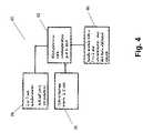
- FIG. 4is a block diagram of an orientation sensor in accordance with one embodiment.
- FIG. 5is a flow diagram of the functionality of the orientation sensor in accordance with one embodiment when determining the orientation of the rod.
- FIG. 6is a flow diagram of the functionality of the orientation sensor in accordance with one embodiment when auto calibrating the orientation sensor in order to determine the orientation of the rod.
- One embodiment of the present inventionis a system for calculating the orientation of a rod through the use of an optical sensor and one or more accelerometers.
- FIG. 1is a perspective front view of a two rod laparoscopy simulator 10 in accordance with one embodiment.
- Simulator 10includes a base 12 that is fixed to ground.
- Each rod 16 , 17is coupled to base 12 through an arm 13 , 14 that rotates around base 12 via an axis that allows the arms to rotate 360°, as indicated by arrow 20 .
- Rods 16 and 17 and associated componentsare identical.
- arm 13is coupled to a platform 40 through an axis that allows platform 40 to rotate 360°, as indicated by arrow 38 .
- Platform 40holds rod 16 in place through collars 41 , 42 .
- Platform 40further includes a circuit board 26 that includes an optical sensor 30 and an accelerometer 28 .
- Other simulatorsmay include only one rod, or may have more than two rods or other objects for which the orientation is determined.
- Rod 16can rotate 360° around a central axis 36 , and can be moved up and down along central axis 36 through the coupling of collars 41 , 42 .
- a handle 32is coupled to the top of rod 16 for manipulating rod 16
- a toolis coupled to the bottom of rod 16 for simulating the cutting, image capturing, clamping, or other tool functions typically used during laparoscopy.
- Handle 32includes an accelerometer 66 for auto calibration purposes.
- Platform 40can also be coupled to base 12 using other mechanical means, such as a gimbal, that allows platform 40 to rotate in at least two degrees of freedom or axes relative to base 12 .
- simulator 10permits four movements for each of rods 16 and 17 : a slide movement along axis 36 ; a rotation of the rod around axis 36 ; a left or right rotation as indicated by arrow 38 (“roll”); and an up and down movement (“pitch”), as indicated by arrow 20 .
- the orientation of the rod through all of these movementsneeds to be sensed and measured so that simulator 10 provides accurate feedback to the user.
- FIG. 2is a perspective rear view of two rod laparoscopy simulator 10 in accordance with one embodiment.
- FIG. 2provides a view of axis 50 that allows platform 40 to rotate as indicated by arrow 38 .
- FIG. 3is a perspective front view of two rod laparoscopy simulator 10 in accordance with one embodiment.
- FIG. 3provides a closer view as compared to FIG. 1 of platform 40 , collars 41 , 42 , circuit board 26 , accelerometer 28 and optical sensor 30 .
- FIG. 4is a block diagram of an orientation sensor 60 in accordance with one embodiment.
- Sensor 60includes a microprocessor 62 that includes a communication port to a host computer that receives the orientation sensor readings and responds accordingly.
- Microprocessor 62can be any type of general purpose processor or controller and includes memory for storing instructions that are executed.
- Optical sensor 30coupled to microprocessor 62 , is a sensor that can detect movement of rod 16 by viewing its surface. Sensor 30 detects the up and down movement of rod 16 (“Y-axis”) and the rotation of rod 16 (“X-axis”).
- Accelerometer 28coupled to microprocessor 60 , in one embodiment is a micro-electro-mechanical systems (“MEMS”) device that determines the pitch (rotation along arrow 20 of FIG. 1 ) and roll (rotation along arrow 38 of FIG. 1 ) of rod 16 .
- Accelerometer 28may be a two or three axes accelerometer or any type of accelerometer that provides positioning information using gravitational comparisons.
- Accelerometer 28may be considered a single accelerometer having two or more axes, or may be considered as comprising multiple accelerometers, one for each axis.
- the four measurements provided by optical sensor 30 and accelerometer 28allow microprocessor 60 to calculate the orientation of rod 16 at all times.
- an accelerometer 66on a handle module that may be a 1 or 2 axis accelerometer and is located on handle 32 .
- Accelerometer 66provides auto calibration for the rotation of rod 16 . Auto calibration may be desired since the sensing of the rotation of rod 16 is done on a relative basis and therefore the starting point of rod 16 should be determined. Accelerometer 66 provides information to microprocessor 62 to calculate the absolute angle of handle 32 .
- FIG. 5is a flow diagram of the functionality of orientation sensor 60 in accordance with one embodiment when determining the orientation of rod 16 .
- the functionality of the flow diagram of FIG. 5is implemented by software stored in memory and executed by a processor. In other embodiments, the functionality can be performed by hardware, or any combination of hardware and software.
- the communication ports and sensorsi.e., accelerometer(s) and optical sensor
- the sensorsare initialized and the sensors are tested.
- the sensorsare read.
- the auto calibration routine(disclosed in more detail in conjunction with FIG. 6 ) is performed.
- the results of the orientation determinationis output at 110 and the flow returns to 104 .
- FIG. 6is a flow diagram of the functionality of orientation sensor 60 in accordance with one embodiment when auto calibrating orientation sensor 60 in order to determine the orientation of rod 16 .
- the functionality of the flow diagram of FIG. 6is implemented by software stored in memory and executed by a processor. In other embodiments, the functionality can be performed by hardware, or any combination of hardware and software.
- auto calibrationbegins.
- rod 16will be at an angle during the majority of its operation since a user will be physically uncomfortable operating simulator 10 when the rods are straight up and down.
- accelerometer 66is read at 116 , and the rotation angle of handle 32 is calculated.
- embodimentscan determine the orientation of rods used for laparoscopy simulation without having to use bulky and expensive angle sensors.
- the combination of an optical sensor and one or two accelerometersenable all movements of the rod to be determined.
- orientation of a rodis disclosed in the above embodiments, in other embodiments the orientation of other objects can be determined.
Landscapes
- Engineering & Computer Science (AREA)
- General Physics & Mathematics (AREA)
- Physics & Mathematics (AREA)
- Health & Medical Sciences (AREA)
- Computational Mathematics (AREA)
- Mathematical Optimization (AREA)
- Medical Informatics (AREA)
- Medicinal Chemistry (AREA)
- Chemical & Material Sciences (AREA)
- Algebra (AREA)
- Theoretical Computer Science (AREA)
- Educational Technology (AREA)
- Mathematical Analysis (AREA)
- General Health & Medical Sciences (AREA)
- Mathematical Physics (AREA)
- Pure & Applied Mathematics (AREA)
- Business, Economics & Management (AREA)
- Educational Administration (AREA)
- Pulmonology (AREA)
- Radiology & Medical Imaging (AREA)
- Length Measuring Devices By Optical Means (AREA)
- Length Measuring Devices With Unspecified Measuring Means (AREA)
- Measurement Of The Respiration, Hearing Ability, Form, And Blood Characteristics Of Living Organisms (AREA)
Abstract
Description
Claims (22)
Priority Applications (2)
| Application Number | Priority Date | Filing Date | Title |
|---|---|---|---|
| US11/779,503US7706000B2 (en) | 2007-07-18 | 2007-07-18 | Orientation sensing of a rod |
| PCT/US2008/066396WO2009011991A2 (en) | 2007-07-18 | 2008-06-10 | Orientation sensing of a rod |
Applications Claiming Priority (1)
| Application Number | Priority Date | Filing Date | Title |
|---|---|---|---|
| US11/779,503US7706000B2 (en) | 2007-07-18 | 2007-07-18 | Orientation sensing of a rod |
Publications (2)
| Publication Number | Publication Date |
|---|---|
| US20090021752A1 US20090021752A1 (en) | 2009-01-22 |
| US7706000B2true US7706000B2 (en) | 2010-04-27 |
Family
ID=40097427
Family Applications (1)
| Application Number | Title | Priority Date | Filing Date |
|---|---|---|---|
| US11/779,503Expired - Fee RelatedUS7706000B2 (en) | 2007-07-18 | 2007-07-18 | Orientation sensing of a rod |
Country Status (2)
| Country | Link |
|---|---|
| US (1) | US7706000B2 (en) |
| WO (1) | WO2009011991A2 (en) |
Cited By (12)
| Publication number | Priority date | Publication date | Assignee | Title |
|---|---|---|---|---|
| US20120041478A1 (en)* | 2002-04-16 | 2012-02-16 | Academisch Medisch Centrum | Instrument for Minimally Invasive Surgery |
| US9554411B1 (en) | 2015-12-30 | 2017-01-24 | DePuy Synthes Products, Inc. | Systems and methods for wirelessly powering or communicating with sterile-packed devices |
| US9579043B2 (en) | 2014-08-28 | 2017-02-28 | DePuy Synthes Products, Inc. | Systems and methods for intraoperatively measuring anatomical orientation |
| US9999448B2 (en) | 2013-03-14 | 2018-06-19 | DePuy Synthes Products, Inc. | Methods and devices for polyaxial screw alignment |
| US10335241B2 (en) | 2015-12-30 | 2019-07-02 | DePuy Synthes Products, Inc. | Method and apparatus for intraoperative measurements of anatomical orientation |
| US10613629B2 (en) | 2015-03-27 | 2020-04-07 | Chad Laurendeau | System and method for force feedback interface devices |
| US10820835B2 (en) | 2016-09-12 | 2020-11-03 | Medos International Sarl | Systems and methods for anatomical alignment |
| US11089975B2 (en) | 2017-03-31 | 2021-08-17 | DePuy Synthes Products, Inc. | Systems, devices and methods for enhancing operative accuracy using inertial measurement units |
| US11335212B2 (en)* | 2017-04-11 | 2022-05-17 | Follou Ab | Surgical simulation arrangement |
| US11468791B2 (en)* | 2013-12-20 | 2022-10-11 | Intuitive Surgical Operations, Inc. | Simulator system for medical procedure training |
| US11464596B2 (en) | 2016-02-12 | 2022-10-11 | Medos International Sarl | Systems and methods for intraoperatively measuring anatomical orientation |
| US11727827B2 (en) | 2012-08-17 | 2023-08-15 | Intuitive Surgical Operations, Inc. | Anatomical model and method for surgical training |
Families Citing this family (9)
| Publication number | Priority date | Publication date | Assignee | Title |
|---|---|---|---|---|
| US8496647B2 (en) | 2007-12-18 | 2013-07-30 | Intuitive Surgical Operations, Inc. | Ribbed force sensor |
| US8561473B2 (en) | 2007-12-18 | 2013-10-22 | Intuitive Surgical Operations, Inc. | Force sensor temperature compensation |
| CN102800233B (en)* | 2012-07-23 | 2014-10-29 | 广东工业大学 | Minimally invasive surgery training device driven by multi-sensor information |
| EP2760003A1 (en)* | 2013-01-24 | 2014-07-30 | Surgical Science Sweden AB | Haptic user interface device for surgical simulation system |
| US11361678B2 (en) | 2013-06-06 | 2022-06-14 | Board Of Regents Of The University Of Nebraska | Portable camera aided simulator (PortCAS) for minimally invasive surgical training |
| US9817019B2 (en) | 2013-11-13 | 2017-11-14 | Intuitive Surgical Operations, Inc. | Integrated fiber bragg grating accelerometer in a surgical instrument |
| RU2679110C1 (en)* | 2017-11-29 | 2019-02-05 | Общество с ограниченной ответственностью "Эйдос - Медицина" | Ventriculoscope simulator |
| US12419713B2 (en) | 2018-11-15 | 2025-09-23 | Intuitive Surgical Operations, Inc. | Surgical instrument with sensor aligned cable guide |
| US12239393B2 (en) | 2020-05-18 | 2025-03-04 | Intuitive Surgical Operations, Inc. | Hard stop that produces a reactive moment upon engagement for cantilever-based force sensing |
Citations (7)
| Publication number | Priority date | Publication date | Assignee | Title |
|---|---|---|---|---|
| US5623582A (en) | 1994-07-14 | 1997-04-22 | Immersion Human Interface Corporation | Computer interface or control input device for laparoscopic surgical instrument and other elongated mechanical objects |
| US6184868B1 (en) | 1998-09-17 | 2001-02-06 | Immersion Corp. | Haptic feedback control devices |
| US6278439B1 (en) | 1995-12-01 | 2001-08-21 | Immersion Corporation | Method and apparatus for shaping force signals for a force feedback device |
| US20030188594A1 (en) | 2002-04-03 | 2003-10-09 | Immersion Corporation | Haptic shifting devices |
| US7296363B2 (en)* | 2004-06-25 | 2007-11-20 | N.B. Inc. | Shape-acceleration measurement device and method |
| US20080162046A1 (en)* | 2006-10-24 | 2008-07-03 | General Electric Company | Method and system for tracking an arrangement of medical apparatuses |
| US20090012532A1 (en)* | 2002-03-06 | 2009-01-08 | Mako Surgical Corp. | Haptic guidance system and method |
- 2007
- 2007-07-18USUS11/779,503patent/US7706000B2/ennot_activeExpired - Fee Related
- 2008
- 2008-06-10WOPCT/US2008/066396patent/WO2009011991A2/enactiveApplication Filing
Patent Citations (7)
| Publication number | Priority date | Publication date | Assignee | Title |
|---|---|---|---|---|
| US5623582A (en) | 1994-07-14 | 1997-04-22 | Immersion Human Interface Corporation | Computer interface or control input device for laparoscopic surgical instrument and other elongated mechanical objects |
| US6278439B1 (en) | 1995-12-01 | 2001-08-21 | Immersion Corporation | Method and apparatus for shaping force signals for a force feedback device |
| US6184868B1 (en) | 1998-09-17 | 2001-02-06 | Immersion Corp. | Haptic feedback control devices |
| US20090012532A1 (en)* | 2002-03-06 | 2009-01-08 | Mako Surgical Corp. | Haptic guidance system and method |
| US20030188594A1 (en) | 2002-04-03 | 2003-10-09 | Immersion Corporation | Haptic shifting devices |
| US7296363B2 (en)* | 2004-06-25 | 2007-11-20 | N.B. Inc. | Shape-acceleration measurement device and method |
| US20080162046A1 (en)* | 2006-10-24 | 2008-07-03 | General Electric Company | Method and system for tracking an arrangement of medical apparatuses |
Non-Patent Citations (4)
| Title |
|---|
| Immersion Corporation: "Virtual Laparoscopic Interface" [Online] 2000, pp. 1-1, XP002509910; http://www.inition.co.uk/inition/pdf/3dinput-immersion-virtual-laparoscpic-interface.pdf. |
| Immersion Corporation: "Virtual Laparoscopic Interface" [Online] 2000, pp. 1-1, XP002509910; http://www.inition.co.uk/inition/pdf/3dinput—immersion—virtual—laparoscpic—interface.pdf. |
| International Search Report and Written Opinion-PCT/US2008/066396. |
| International Search Report and Written Opinion—PCT/US2008/066396. |
Cited By (26)
| Publication number | Priority date | Publication date | Assignee | Title |
|---|---|---|---|---|
| US8992564B2 (en)* | 2002-04-16 | 2015-03-31 | Academisch Medisch Centrum Van De Universiteit Van Amsterdam | Instrument for minimally invasive surgery |
| US20120041478A1 (en)* | 2002-04-16 | 2012-02-16 | Academisch Medisch Centrum | Instrument for Minimally Invasive Surgery |
| US11727827B2 (en) | 2012-08-17 | 2023-08-15 | Intuitive Surgical Operations, Inc. | Anatomical model and method for surgical training |
| US9999448B2 (en) | 2013-03-14 | 2018-06-19 | DePuy Synthes Products, Inc. | Methods and devices for polyaxial screw alignment |
| US10888359B2 (en) | 2013-03-14 | 2021-01-12 | DePuy Synthes Products, Inc. | Methods and devices for polyaxial screw alignment |
| US11468791B2 (en)* | 2013-12-20 | 2022-10-11 | Intuitive Surgical Operations, Inc. | Simulator system for medical procedure training |
| US9993177B2 (en) | 2014-08-28 | 2018-06-12 | DePuy Synthes Products, Inc. | Systems and methods for intraoperatively measuring anatomical orientation |
| US9579043B2 (en) | 2014-08-28 | 2017-02-28 | DePuy Synthes Products, Inc. | Systems and methods for intraoperatively measuring anatomical orientation |
| US11395604B2 (en) | 2014-08-28 | 2022-07-26 | DePuy Synthes Products, Inc. | Systems and methods for intraoperatively measuring anatomical orientation |
| US12207913B2 (en) | 2014-08-28 | 2025-01-28 | DePuy Synthes Products, Inc. | Systems and methods for intraoperatively measuring anatomical orientation |
| US10613629B2 (en) | 2015-03-27 | 2020-04-07 | Chad Laurendeau | System and method for force feedback interface devices |
| US10743944B2 (en) | 2015-12-30 | 2020-08-18 | DePuy Synthes Products, Inc. | Method and apparatus for intraoperative measurements of anatomical orientation |
| US10335241B2 (en) | 2015-12-30 | 2019-07-02 | DePuy Synthes Products, Inc. | Method and apparatus for intraoperative measurements of anatomical orientation |
| US9554411B1 (en) | 2015-12-30 | 2017-01-24 | DePuy Synthes Products, Inc. | Systems and methods for wirelessly powering or communicating with sterile-packed devices |
| US11160619B2 (en) | 2015-12-30 | 2021-11-02 | DePuy Synthes Products, Inc. | Method and apparatus for intraoperative measurements of anatomical orientation |
| US11223245B2 (en) | 2015-12-30 | 2022-01-11 | DePuy Synthes Products, Inc. | Systems and methods for wirelessly powering or communicating with sterile-packed devices |
| US10714987B2 (en) | 2015-12-30 | 2020-07-14 | DePuy Synthes Products, Inc. | Systems and methods for wirelessly powering or communicating with sterile-packed devices |
| US10396606B2 (en) | 2015-12-30 | 2019-08-27 | DePuy Synthes Products, Inc. | Systems and methods for wirelessly powering or communicating with sterile-packed devices |
| US11563345B2 (en) | 2015-12-30 | 2023-01-24 | Depuy Synthes Products, Inc | Systems and methods for wirelessly powering or communicating with sterile-packed devices |
| US11660149B2 (en) | 2015-12-30 | 2023-05-30 | DePuy Synthes Products, Inc. | Method and apparatus for intraoperative measurements of anatomical orientation |
| US12186136B2 (en) | 2016-02-12 | 2025-01-07 | Medos International Sàrl | Systems and methods for intraoperatively measuring anatomical orientation |
| US11464596B2 (en) | 2016-02-12 | 2022-10-11 | Medos International Sarl | Systems and methods for intraoperatively measuring anatomical orientation |
| US10820835B2 (en) | 2016-09-12 | 2020-11-03 | Medos International Sarl | Systems and methods for anatomical alignment |
| US12121344B2 (en) | 2016-09-12 | 2024-10-22 | Medos International Srl | Systems and methods for anatomical alignment |
| US11089975B2 (en) | 2017-03-31 | 2021-08-17 | DePuy Synthes Products, Inc. | Systems, devices and methods for enhancing operative accuracy using inertial measurement units |
| US11335212B2 (en)* | 2017-04-11 | 2022-05-17 | Follou Ab | Surgical simulation arrangement |
Also Published As
| Publication number | Publication date |
|---|---|
| WO2009011991A2 (en) | 2009-01-22 |
| US20090021752A1 (en) | 2009-01-22 |
| WO2009011991A3 (en) | 2009-03-05 |
Similar Documents
| Publication | Publication Date | Title |
|---|---|---|
| US7706000B2 (en) | Orientation sensing of a rod | |
| US20220233224A1 (en) | Alignment apparatus for use in hip arthroplasty | |
| CN111212609B (en) | Systems and methods using augmented reality with shape alignment for placing medical devices in bones | |
| Picerno et al. | A spot check for assessing static orientation consistency of inertial and magnetic sensing units | |
| KR101427730B1 (en) | Camera registration method for augmented reality of surgical navigation system | |
| US12064186B2 (en) | Systems and methods for simulating three-dimensional orientations of surgical hardware devices about an insertion point of an anatomy | |
| CN105848552A (en) | Method for measuring distance by using endoscope, and endoscope system | |
| WO2014110669A1 (en) | Method and apparatus for determining a relative orientation of points on a rigid body | |
| WO2004112610A3 (en) | Surgical orientation device and method | |
| JP2006506654A (en) | Level, angle and distance measuring device | |
| Schneider et al. | Development and testing of a new magnetic-tracking device for image guidance | |
| EP2600308A2 (en) | Information processing apparatus, information processing method, program and computer-readable storage medium | |
| JP4785416B2 (en) | Position and orientation measurement method and apparatus | |
| JP7611982B2 (en) | A camera tracking system for computer-aided surgical navigation. | |
| Oropesa et al. | Feasibility of tracking laparoscopic instruments in a box trainer using a Leap Motion Controller | |
| US11224787B2 (en) | Swing measurement device, swing measurement method, and swing measurement program | |
| CN113384347B (en) | Robot calibration method, device, equipment and storage medium | |
| US12394086B2 (en) | Accuracy check and automatic calibration of tracked instruments | |
| EP4169469A1 (en) | Laparoskopic camera arrangement and method for camera alignment error correction | |
| Nocerino et al. | Low-cost human motion capture system for postural analysis onboard ships | |
| JP2014079474A (en) | Golf club head, swing analysis system using the same, and swing measuring method | |
| DE | TooltrackTM: a compact, low-cost system for measuring surgical tool motion | |
| US20240374313A1 (en) | System and method for simulating an orientation of a medical device at an insertion point | |
| CN114424018A (en) | Angle Laser Technology (ALT) based form length measurement apparatus and related methods | |
| Bracken et al. | Multimodal noncontact tracking of surgical instruments |
Legal Events
| Date | Code | Title | Description |
|---|---|---|---|
| AS | Assignment | Owner name:IMMERSION MEDICAL, INC., MARYLAND Free format text:ASSIGNMENT OF ASSIGNORS INTEREST;ASSIGNORS:COHEN, ROB;XU, TIANNING;REEL/FRAME:019574/0379 Effective date:20070717 Owner name:IMMERSION MEDICAL, INC.,MARYLAND Free format text:ASSIGNMENT OF ASSIGNORS INTEREST;ASSIGNORS:COHEN, ROB;XU, TIANNING;REEL/FRAME:019574/0379 Effective date:20070717 | |
| STCF | Information on status: patent grant | Free format text:PATENTED CASE | |
| FPAY | Fee payment | Year of fee payment:4 | |
| MAFP | Maintenance fee payment | Free format text:PAYMENT OF MAINTENANCE FEE, 8TH YEAR, LARGE ENTITY (ORIGINAL EVENT CODE: M1552) Year of fee payment:8 | |
| FEPP | Fee payment procedure | Free format text:MAINTENANCE FEE REMINDER MAILED (ORIGINAL EVENT CODE: REM.); ENTITY STATUS OF PATENT OWNER: LARGE ENTITY | |
| LAPS | Lapse for failure to pay maintenance fees | Free format text:PATENT EXPIRED FOR FAILURE TO PAY MAINTENANCE FEES (ORIGINAL EVENT CODE: EXP.); ENTITY STATUS OF PATENT OWNER: LARGE ENTITY | |
| STCH | Information on status: patent discontinuation | Free format text:PATENT EXPIRED DUE TO NONPAYMENT OF MAINTENANCE FEES UNDER 37 CFR 1.362 | |
| FP | Lapsed due to failure to pay maintenance fee | Effective date:20220427 |