US7705613B2 - Sensitivity capacitive sensor - Google Patents
Sensitivity capacitive sensorDownload PDFInfo
- Publication number
- US7705613B2 US7705613B2US11/619,482US61948207AUS7705613B2US 7705613 B2US7705613 B2US 7705613B2US 61948207 AUS61948207 AUS 61948207AUS 7705613 B2US7705613 B2US 7705613B2
- Authority
- US
- United States
- Prior art keywords
- sensor
- chip
- cover plate
- vias
- connection points
- Prior art date
- Legal status (The legal status is an assumption and is not a legal conclusion. Google has not performed a legal analysis and makes no representation as to the accuracy of the status listed.)
- Active, expires
Links
Images


Classifications
- G—PHYSICS
- G06—COMPUTING OR CALCULATING; COUNTING
- G06V—IMAGE OR VIDEO RECOGNITION OR UNDERSTANDING
- G06V40/00—Recognition of biometric, human-related or animal-related patterns in image or video data
- G06V40/10—Human or animal bodies, e.g. vehicle occupants or pedestrians; Body parts, e.g. hands
- G06V40/12—Fingerprints or palmprints
- G06V40/13—Sensors therefor
- G06V40/1306—Sensors therefor non-optical, e.g. ultrasonic or capacitive sensing
- H—ELECTRICITY
- H01—ELECTRIC ELEMENTS
- H01L—SEMICONDUCTOR DEVICES NOT COVERED BY CLASS H10
- H01L2224/00—Indexing scheme for arrangements for connecting or disconnecting semiconductor or solid-state bodies and methods related thereto as covered by H01L24/00
- H01L2224/01—Means for bonding being attached to, or being formed on, the surface to be connected, e.g. chip-to-package, die-attach, "first-level" interconnects; Manufacturing methods related thereto
- H01L2224/42—Wire connectors; Manufacturing methods related thereto
- H01L2224/47—Structure, shape, material or disposition of the wire connectors after the connecting process
- H01L2224/48—Structure, shape, material or disposition of the wire connectors after the connecting process of an individual wire connector
- H01L2224/4805—Shape
- H01L2224/4809—Loop shape
- H01L2224/48091—Arched
- H—ELECTRICITY
- H01—ELECTRIC ELEMENTS
- H01L—SEMICONDUCTOR DEVICES NOT COVERED BY CLASS H10
- H01L2224/00—Indexing scheme for arrangements for connecting or disconnecting semiconductor or solid-state bodies and methods related thereto as covered by H01L24/00
- H01L2224/80—Methods for connecting semiconductor or other solid state bodies using means for bonding being attached to, or being formed on, the surface to be connected
- H01L2224/85—Methods for connecting semiconductor or other solid state bodies using means for bonding being attached to, or being formed on, the surface to be connected using a wire connector
- H01L2224/85909—Post-treatment of the connector or wire bonding area
- H01L2224/8592—Applying permanent coating, e.g. protective coating
- Y—GENERAL TAGGING OF NEW TECHNOLOGICAL DEVELOPMENTS; GENERAL TAGGING OF CROSS-SECTIONAL TECHNOLOGIES SPANNING OVER SEVERAL SECTIONS OF THE IPC; TECHNICAL SUBJECTS COVERED BY FORMER USPC CROSS-REFERENCE ART COLLECTIONS [XRACs] AND DIGESTS
- Y10—TECHNICAL SUBJECTS COVERED BY FORMER USPC
- Y10T—TECHNICAL SUBJECTS COVERED BY FORMER US CLASSIFICATION
- Y10T29/00—Metal working
- Y10T29/49—Method of mechanical manufacture
- Y10T29/49002—Electrical device making
- Y10T29/49007—Indicating transducer
- Y—GENERAL TAGGING OF NEW TECHNOLOGICAL DEVELOPMENTS; GENERAL TAGGING OF CROSS-SECTIONAL TECHNOLOGIES SPANNING OVER SEVERAL SECTIONS OF THE IPC; TECHNICAL SUBJECTS COVERED BY FORMER USPC CROSS-REFERENCE ART COLLECTIONS [XRACs] AND DIGESTS
- Y10—TECHNICAL SUBJECTS COVERED BY FORMER USPC
- Y10T—TECHNICAL SUBJECTS COVERED BY FORMER US CLASSIFICATION
- Y10T29/00—Metal working
- Y10T29/49—Method of mechanical manufacture
- Y10T29/49002—Electrical device making
- Y10T29/49117—Conductor or circuit manufacturing
- Y10T29/49124—On flat or curved insulated base, e.g., printed circuit, etc.
- Y10T29/4913—Assembling to base an electrical component, e.g., capacitor, etc.
- Y10T29/49144—Assembling to base an electrical component, e.g., capacitor, etc. by metal fusion
Definitions
- This inventionrelates to capacitive sensors and, more particularly, to capacitive sensors for use in fingerprint detection.
- Fingerprintshave long been used for authentication purposes. While originally done for purposes of criminal investigation, in the electronic age, fingerprint detection has become a prevalent form of identification for, among others, security purposes. In such cases, the fingerprint pattern must be discerned and verified.
- fingerprint sensorsare used to, in effect, generate a digital picture of the ridges and valleys that form the loops and whorls on a finger surface. This is done by having an array of cells, in which each corresponds to a single pixel of the fingerprint image. There are different types of sensors for doing so and their resolution is on the order of about 350 to 512 dpi, although higher pixel resolutions can be found. In order to accomplish the foregoing, capacitive sensors are commonly used.
- capacitive sensoruses one electrode for each pixel.
- the electrodemeasures the capacity relative to a neighbor electrode with the capacitance being different if a pixel is on a groove or on a ridge.
- Another type of capacitive sensoris similar to the previous one, except that capacitance is measured between the pixel and ground.
- Yet another type, more indicative of typical commercial systems,involves some combination of these two types.
- the capacitanceis measured using AC voltage on an inter-electrode and/or electrode to ground basis.
- the forgoing types of sensorscan be used in a scanner-like configuration to obtain an image of the fingerprint using electrical current instead of light.
- FIG. 1illustrates a simplified example of a portion 100 of a simple capacitive sensor.
- the sensoris made up of one or more semiconductor chips containing an array of individual cells 102 a , 102 b that are each smaller than the width of one ridge or valley on a finger, in the simplified example of FIG. 1 , ⁇ 50 ⁇ m.
- each cell 102 a , 102 bcorresponds to a pixel and includes two conductor plates 104 a , 104 b , covered with an insulating layer 106 which acts as a capacitor dielectric.
- the sensoris connected to an integrator that includes an inverting operational amplifier 108 .
- the inverting amplifier 108alters one current based on fluctuations in another current. Specifically, the inverting amplifier alters a supply voltage. The alteration is based on the relative voltage of two inputs, called the inverting terminal 110 and the non-inverting terminal 112 .
- the non-inverting terminalis connected to ground, and the inverting terminal is connected to a reference voltage supply 114 and a feedback loop 116 .
- the feedback loop 116which is also connected to the amplifier output 118 , includes the two conductor plates 104 a , 104 b .
- the two conductor plates 104 a , 104 bform a capacitor.
- the surface of the fingeracts as a third capacitor plate and is separated from the two conductor palates by at least the insulating layer 106 .
- a greater capacitancewill indicate a ridge 120 and a lesser capacitance will indicate a valley 122 (because of the air located in the valley) and thus, a ridge 120 will result in a different output signal from the cell than will result from the presence of a valley 122 .
- FIG. 2illustrates, in overly simplified form, a top view of a capacitive sensor array 200 incorporating cells 202 such as, for example, those of FIG. 1 or some other cell design.
- Each cellis typically addressed in a known manner, whether in parallel, in series, or some combination of the two (i.e. a scan), to obtain the image and, in some cases, to perform more complex operations like sub sampling.
- the outputis provided to a analog signal processing circuitry (to allow for adjustment of gain and offset) and then to an A/D converter to convert the analog values to digital values.
- the digital valuescan then be processed as needed by, for example, an appropriately programmed microprocessor.
- the sensorwill be able to have direct contact with the finger to be read.
- a cover plateis placed over the sensor.
- This cover plateis typically glass and of sufficient thickness to resist the pressures of at least normal use and sufficient durability to allow for cleaning when necessary.
- the cover platealso increases the distance between the sensor plates and the finger, thereby reducing the sensitivity—and thus, accuracy—of the sensor. This is because, as should be evident from the above, the further the distance between the cover plate surface and the sensor, relative to the distance between the top of a ridge and the bottom of a valley, the more difficult it becomes to discriminate between ridges and valleys.
- One aspect of the improved sensitivity capacitive fingerprint sensorinvolves forming vias from a first side of a sensor chip having an array of capacitive sensors, making the vias electrically conductive, and attaching a cover plate over the first side of the sensor chip spaced from the sensor chip by a distance of less than 25 ⁇ m.
- Another aspect of the improved sensitivity capacitive fingerprint sensorinvolves a capacitive sensor array chip including multiple sensor cells and electrically conductive, through-chip vias extending from connection points for sensor cell circuitry to a back side of the capacitive sensor array chip, a chip including active detection circuitry and electrical connection points, the electrical connection points being respectively connected to corresponding ones of the sensor cell circuitry connection points, and a cover plate, disposed above the sensor cells at a spacing of less than 25 ⁇ m.
- FIG. 1illustrates a simplified example of a portion 100 of a simple capacitive sensor
- FIG. 2illustrates, in overly simplified form, a top view of a capacitive sensor array incorporating cells
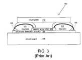
- FIG. 3illustrates, in simplified form, a side view of a portion 300 of a typical capacitive fingerprint sensor device of the prior art
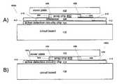
- FIG. 4Aillustrates one representative example variant
- FIG. 4Billustrates an alternative variant similar to that of FIG. 4A ;
- FIG. 5illustrates yet another alternative variant similar to that of FIG. 4A ;
- FIG. 6illustrates a representative spacer for a sensor chip.
- FIG. 3illustrates, in simplified form, a side view of a portion 300 of a typical capacitive fingerprint sensor device of the prior art.
- the deviceis made up of a capacitive sensor array chip 302 (an array of individual pixel cells such as previously described), active electronic detection circuitry 304 that is used to, for example, access and receive the individual pixel values from the capacitive sensor array chip 302 , a circuit board 306 to which the active electronic detection circuitry 304 is electronically connected and physically mounted, and, although not shown, a processor which can be used to analyze the pixel values as necessary for the desired application.
- a capacitive sensor array chip 302an array of individual pixel cells such as previously described
- active electronic detection circuitry 304that is used to, for example, access and receive the individual pixel values from the capacitive sensor array chip 302
- a circuit board 306to which the active electronic detection circuitry 304 is electronically connected and physically mounted
- a processorwhich can be used to analyze the pixel values as necessary for the desired application.
- the capacitive sensor array chip 302is electrically connected to the active detection circuitry by wirebonds 308 , extending from a contact on each to a contact on the other, which have a typical loop height (i.e. from the sensor array chip 302 surface to the top of the wire loop) of between about 75 ⁇ m and 125 ⁇ m.
- the wire loopsare protected by a material, for example, a nonconductive insulator that also acts to maintain the spacing between the sensors of the sensor array chip 302 and a cover plate 312 positioned over the individual cells of the sensor chip 302 .
- the cover plate 312is of a material and thickness sufficient to protect the sensors themselves while allowing for the ability to discriminate between a pixel value indicative of a ridge from that of a valley at the distance needed to allow for appropriate clearance, for example about 25 ⁇ m, over the wirebond loops.
- the cover plateis typically positioned at least 100 ⁇ m or more above the cells of the sensor array.
- the teachings thereinallow for via types, densities and placement that was previously unachievable and can be performed on a chip, die or wafer scale.
- One of the advantages to the approaches described in those applicationsis that it allows one to extend a contact from one side of a chip to the opposite side of the chip (with or without rerouting) using such small deep vias.
- Such techniquesallow for high via densities, making it ideal for use with capacitive sensors array chips to eliminate the need to use wirebond connections to connect the capacitive sensor array to the active detection circuitry. As a result, the distance between the cover plate and the sensor array can be reduced significantly.
- the capacitive sensor devicescan be created on a wafer or chip scale as desired.
- the individual capacitive sensors themselvesare created in, for example, the conventional manner such that conventional wirebond contact pads are created about the periphery of the area that will become the sensor array chip or, in some implementations, smaller pads are created and/or pads are created at locations on the die other than about the periphery.
- through-chip viasare created and made electrically conductive using one or more of the approaches described in the applications incorporated by reference above, for example, single conductor, coaxial or even triaxial conductors.
- one or more of the contact formation techniquescan be used to enable the chip to be hybridized to a chip carrying the active device circuitry, if the sensor chip does not, or will not, have the active device circuitry.
- a cover plateis optionally attached prior to dicing of the individual chips from the wafer.
- the cover platecan be placed at the minimum clearance spacing (i.e. directly on the sensors if possible) or at such other desired minimum clearance spacing using, for example, minimal standoffs that can be added to, or formed on, the wafer (again, on a wafer or individual piece basis). In this manner, the spacing between the outer surface of the cover plate and the sensor surface is both greatly reduced and can be more tightly controlled than would have been possible if allowance for wirebond loops was necessary.
- the chips, and cover if already attachedcan be diced from the wafer for bonding to the active detection circuitry.
- the chips and covercan be diced separately and attached in a “chip at a time” manner.
- a rerouting interposercan also optionally be used to further route the connections from the back side of the sensor chip to the proper locations for joining with the active detection circuitry chip.
- the interposercan be made from any material that can carry electrical connections, from ceramic to plastics to semiconductor materials, the only requirement being the ability to create conductive through-holes and routing patterns on either or both sides.
- the interposercan optionally also act as the “package” for the assembly if the sensor chip and active detection circuitry chip are one and the same.
- an interposerincreases the overall height, since it is below the sensor chip it does not adversely affect the sensitivity because it does not increase the distance between the cover and sensor array.
- the sensor chip and the active detection circuitryare not one and the same, the sensor chip and cover plate unit is joined to the active detection circuitry.
- FIG. 4Aillustrates one representative example variant achieved by this approach.
- the device 400is made up of a capacitive sensor array chip 402 with conductive through-chip vias 404 , such as described above, that extend the contacts 406 of the array chip 402 through to the back side of the array chip 402 .
- a rerouting interposer 408includes rerouting traces (not shown) in this case on the top and bottom, and its own conductive through-via 410 , that bridges the connection between the vias 404 and the contacts 412 on the active detection circuitry chip 414 .
- the active detection circuitry chip 414will typically itself be attached to a circuit board 416 .
- the cover plate 418can be brought much closer to the sensor array cells than could be done when wirebonds are used.
- the spacing between the bottom surface of the cover plate 418 and the highest topographical point on the sensor array chipcan be as small as 25 ⁇ m or less, and could typically even be 10 ⁇ m or less.
- the distancecould be as close to zero as would be allowed by the thickness of whatever adhesive was used to attach the cover plate 418 and/or the likely flexure (if any) of the cover plate 418 itself during use.
- the interposercan employ conductive vias formed as described in the foregoing applications, or formed using more simple processes such as drilling an insulator or plastic sheet and filling the holes with a metal.
- FIG. 4Billustrates an alternative variant 400 b similar to that of FIG. 4A except that this variant does not use an interposer. Instead, the connection between the vias 404 and the contacts 412 is made up of traces 420 on the surface of the active detection circuitry chip 414 itself, those traces having been made using any suitable known method(s).
- the detection circuitry chipcan also have other circuitry on it.
- the active detection circuitry chipcan also function as an interposer or only have part of the active detection circuitry on it such that it must be joined to another chip to provide the full active detection circuitry function. In such cases, the amalgam of the two would be connected to the sensor array chip, and ultimately a package or package chip as desired.
- FIG. 5illustrates yet another alternative variant similar to that of FIG. 4A .
- the cover plateis maintained at a specified distance from the sensor array chip 402 by spacers 502 of a fixed height “h” placed between the interposer 408 and the cover plate 418 .
- hthe height placed between the interposer 408 and the cover plate 418 .
- FIG. 5includes an interposer 408
- the same approachcould be readily translated to the variant of FIG. 4B (i.e. the spacers could rest on the active detection circuitry chip 414 itself) or even to a variant where the spacers 502 rested on the circuit board 416 or some other component (not shown).
- the vias 504are not just located at the periphery of the array chip 402 , but rather some vias are located at places within the boundaries of the chip other than at the periphery. Of course, it will be recognized that in yet other variants, all of the vias could be located in places other than at the periphery if desired.
- the spacers 502could be fabricated as individual frames such that only one spacer per sensor chip would be needed.
- such an approachwould allow the spacers to also be attached on an individual or collective wafer-like basis by forming multiple frames on a wafer that can be aligned with the sensor chip itself.
- FIG. 6whether such frames were attached prior to dicing or post dicing, such an approach would allow the frame(s) 602 to be attached to their respective sensor array chips 600 in a manner that forms a hermetic seal about the sensor array chip 600 using, for example, an approach described in the above-incorporated applications, or some other hermetic or non-hermetic approach.
- the approachcan optionally be performed on a wafer scale basis using a wafer-like element that, post dicing, will become the individual cover plates.
- the above processis performed in the manner described (with or without the optional spacers/frames) except, the cover plates are discrete pieces sized to fit an individual sensor chip.
- the cover plateinstead of applying the cover plate on a full wafer basis as above, the individual cover plates can be applied before dicing using conventional “pick-and-place” techniques.
- the chipscan be diced from the wafer before the cover plates are applied (i.e. things are done on an individual chip basis, with the cover plate being applied after individual chips have been separated from the wafer).
- amalgamated componentscan also optionally be connected to a package or a package chip as desired.
- the above approachis closely tied to use of conventional sensor array and detection circuitry chips.
- the same techniquescan be used to greater advantage with chips that have been designed to accommodate one of the via approaches.
- the high density, small size nature of the via techniquesmeans that vias can be formed directly below each cell, and connect to, the appropriate connection points of the individual pixel cells.
- the sensor chipcan be smaller, because the peripheral connection pads are not required.
- the sensor chipscan be made less complex, because there is no need to route the cells to the periphery.
- rerouting of those connectionscan then be handled on a separate interposer, using backend wafer processing techniques, or such other approaches as desired.
- the lengths of the connection runs on the sensor chipcan be more easily equalized and the distance between the pixels and the components on the active detection circuitry can be reduced.
- connection points on the active detection circuitry chipcan be similarly concentrated and will be more compact. This can free up real estate on the chip that can be used for other purposes.
Landscapes
- Engineering & Computer Science (AREA)
- Human Computer Interaction (AREA)
- Physics & Mathematics (AREA)
- General Physics & Mathematics (AREA)
- Multimedia (AREA)
- Theoretical Computer Science (AREA)
- Measurement Of Length, Angles, Or The Like Using Electric Or Magnetic Means (AREA)
- Image Input (AREA)
Abstract
Description
Claims (14)
Priority Applications (3)
| Application Number | Priority Date | Filing Date | Title |
|---|---|---|---|
| US11/619,482US7705613B2 (en) | 2007-01-03 | 2007-01-03 | Sensitivity capacitive sensor |
| PCT/US2007/089051WO2008085771A2 (en) | 2007-01-03 | 2007-12-28 | Improved sensitivity capacitive sensor |
| US12/616,613US8499434B2 (en) | 2007-01-03 | 2009-11-11 | Method of making a capacitive sensor |
Applications Claiming Priority (1)
| Application Number | Priority Date | Filing Date | Title |
|---|---|---|---|
| US11/619,482US7705613B2 (en) | 2007-01-03 | 2007-01-03 | Sensitivity capacitive sensor |
Related Child Applications (1)
| Application Number | Title | Priority Date | Filing Date |
|---|---|---|---|
| US12/616,613DivisionUS8499434B2 (en) | 2007-01-03 | 2009-11-11 | Method of making a capacitive sensor |
Publications (2)
| Publication Number | Publication Date |
|---|---|
| US20080157787A1 US20080157787A1 (en) | 2008-07-03 |
| US7705613B2true US7705613B2 (en) | 2010-04-27 |
Family
ID=39582967
Family Applications (2)
| Application Number | Title | Priority Date | Filing Date |
|---|---|---|---|
| US11/619,482Active2027-10-19US7705613B2 (en) | 2007-01-03 | 2007-01-03 | Sensitivity capacitive sensor |
| US12/616,613Active2029-07-29US8499434B2 (en) | 2007-01-03 | 2009-11-11 | Method of making a capacitive sensor |
Family Applications After (1)
| Application Number | Title | Priority Date | Filing Date |
|---|---|---|---|
| US12/616,613Active2029-07-29US8499434B2 (en) | 2007-01-03 | 2009-11-11 | Method of making a capacitive sensor |
Country Status (2)
| Country | Link |
|---|---|
| US (2) | US7705613B2 (en) |
| WO (1) | WO2008085771A2 (en) |
Cited By (9)
| Publication number | Priority date | Publication date | Assignee | Title |
|---|---|---|---|---|
| EP2774891A1 (en) | 2013-03-05 | 2014-09-10 | Ams Ag | Semiconductor device with capacitive sensor and integrated circuit |
| CN104156712A (en)* | 2014-08-26 | 2014-11-19 | 南昌欧菲生物识别技术有限公司 | Fingerprint recognition and detection assembly and electronic device |
| US9305959B2 (en) | 2013-06-05 | 2016-04-05 | Apple Inc. | Biometric sensor chip having distributed sensor and control circuitry |
| US9460332B1 (en) | 2013-09-09 | 2016-10-04 | Apple Inc. | Capacitive fingerprint sensor including an electrostatic lens |
| US9501685B2 (en) | 2013-02-22 | 2016-11-22 | Idex Asa | Integrated finger print sensor |
| US9697409B2 (en) | 2013-09-10 | 2017-07-04 | Apple Inc. | Biometric sensor stack structure |
| US20170323134A1 (en)* | 2014-11-10 | 2017-11-09 | Senvis Co. Ltd. | Charge transfer circuit for capacitive sensing and apparatus for detecting fingerprint having thereof |
| US10095906B2 (en) | 2014-02-21 | 2018-10-09 | Idex Asa | Sensor employing overlapping grid lines and conductive probes for extending a sensing surface from the grid lines |
| US11922718B2 (en) | 2021-10-20 | 2024-03-05 | Samsung Electronics Co., Ltd. | Fingerprint sensor package and sensor package |
Families Citing this family (18)
| Publication number | Priority date | Publication date | Assignee | Title |
|---|---|---|---|---|
| US8143719B2 (en)* | 2007-06-07 | 2012-03-27 | United Test And Assembly Center Ltd. | Vented die and package |
| US8344503B2 (en)* | 2008-11-25 | 2013-01-01 | Freescale Semiconductor, Inc. | 3-D circuits with integrated passive devices |
| TW201044284A (en)* | 2009-06-09 | 2010-12-16 | Egis Technology Inc | Image sensing device adapted to flat surface design |
| EP2558978B1 (en) | 2010-04-15 | 2016-06-29 | Apple Inc. | Finger sensor including capacitive lens and associated methods |
| US8866302B2 (en)* | 2011-01-25 | 2014-10-21 | Infineon Technologies Ag | Device including two semiconductor chips and manufacturing thereof |
| TWI493187B (en)* | 2014-02-17 | 2015-07-21 | Morevalued Technology Co Let | Biometrics sensor having flat contact surface formed by signal extending structure and method of manufacturing such sensor |
| CN104898314B (en)* | 2014-03-07 | 2018-01-05 | 敦泰电子有限公司 | Display device and its drive circuit and driving method, electronic equipment |
| CN104051366B (en)* | 2014-07-01 | 2017-06-20 | 苏州晶方半导体科技股份有限公司 | Fingerprint recognition chip-packaging structure and method for packing |
| TWI569211B (en)* | 2014-12-26 | 2017-02-01 | 義隆電子股份有限公司 | Sensing method and device of fingerprint sensor |
| SE1551288A1 (en)* | 2015-06-08 | 2016-12-09 | Fingerprint Cards Ab | Fingerprint sensing device with interposer structure |
| TW201643772A (en)* | 2015-06-08 | 2016-12-16 | 指紋卡公司 | Fingerprint sensing device with interposer structure |
| US9740908B2 (en)* | 2015-11-09 | 2017-08-22 | Contek Life Science Co., Ltd. | Capacitive fingerprint sensor and package method thereof |
| CN106682564A (en)* | 2015-11-09 | 2017-05-17 | 康达生命科学有限公司 | Capacitive fingerprint sensor and packaging method thereof |
| CN106852695A (en)* | 2015-12-08 | 2017-06-16 | 康达生命科学有限公司 | Capacitive fingerprint sensor |
| WO2018191901A1 (en)* | 2017-04-20 | 2018-10-25 | 深圳市汇顶科技股份有限公司 | Biometric identification device and manufacturing method for a protective cover plate |
| CN107450215B (en)* | 2017-08-31 | 2020-07-31 | 厦门天马微电子有限公司 | Array substrate, touch panel, touch display device and driving method thereof |
| CN109918966B (en)* | 2017-12-12 | 2021-02-05 | 中芯国际集成电路制造(北京)有限公司 | Fingerprint identification device, manufacturing method thereof, mobile terminal and fingerprint lock |
| CN113218437B (en)* | 2021-04-30 | 2022-05-13 | 华中师范大学 | High-density charge sensor chip large-area array fault-tolerant network readout device and method |
Citations (50)
| Publication number | Priority date | Publication date | Assignee | Title |
|---|---|---|---|---|
| US5100480A (en) | 1990-04-18 | 1992-03-31 | Mitsubishi Denki Kabushiki Kaisha | Solar cell and method for manufacturing the same |
| EP0516866A1 (en) | 1991-05-03 | 1992-12-09 | International Business Machines Corporation | Modular multilayer interwiring structure |
| US5220530A (en) | 1990-08-07 | 1993-06-15 | Oki Electric Industry Co., Ltd. | Semiconductor memory element and method of fabricating the same |
| US5447076A (en) | 1990-09-01 | 1995-09-05 | Ziegler; Karlheinz | Capacitive force sensor |
| US5563084A (en) | 1994-09-22 | 1996-10-08 | Fraunhofer-Gesellschaft zur F orderung der angewandten Forschung e.V. | Method of making a three-dimensional integrated circuit |
| US5587119A (en) | 1994-09-14 | 1996-12-24 | E-Systems, Inc. | Method for manufacturing a coaxial interconnect |
| US5708569A (en) | 1993-04-07 | 1998-01-13 | Zycon Corporation | Annular circuit components coupled with printed circuit board through-hole |
| US5814889A (en) | 1995-06-05 | 1998-09-29 | Harris Corporation | Intergrated circuit with coaxial isolation and method |
| US5872338A (en) | 1996-04-10 | 1999-02-16 | Prolinx Labs Corporation | Multilayer board having insulating isolation rings |
| US5929524A (en) | 1995-12-14 | 1999-07-27 | Nec Corporation | Semiconductor device having ring-shaped conductive spacer which connects wiring layers |
| US5962922A (en) | 1998-03-18 | 1999-10-05 | Wang; Bily | Cavity grid array integrated circuit package |
| US6011859A (en) | 1997-07-02 | 2000-01-04 | Stmicroelectronics, Inc. | Solid state fingerprint sensor packaging apparatus and method |
| US6037665A (en) | 1997-03-03 | 2000-03-14 | Nec Corporation | Mounting assembly of integrated circuit device and method for production thereof |
| US6184066B1 (en) | 1997-05-28 | 2001-02-06 | Matsushita Electric Industrial Co., Ltd. | Method for fabricating semiconductor device |
| US6215114B1 (en) | 1997-09-25 | 2001-04-10 | Canon Kk | Optical probe for detecting or irradiating light and near-field optical microscope having such probe and manufacturing method of such probe |
| US20010001292A1 (en) | 1998-04-07 | 2001-05-17 | Bertin Claude Louis | Through-chip conductors for low inductance chip-to-chip integration and off-chip connections |
| US20010033509A1 (en) | 1998-11-23 | 2001-10-25 | Micron Technology, Inc. | Stacked integrated circuits |
| US6316737B1 (en) | 1999-09-09 | 2001-11-13 | Vlt Corporation | Making a connection between a component and a circuit board |
| US20010048166A1 (en) | 2000-05-26 | 2001-12-06 | Takashi Miyazaki | Flip chip type semiconductor device and method of manufactruing the same |
| US20020053726A1 (en) | 2000-11-09 | 2002-05-09 | Kazuyuki Mikubo | Semiconductor device attaining both high speed processing and sufficient cooling capacity |
| US20020102835A1 (en) | 2000-09-07 | 2002-08-01 | Michele Stucchi | Method of fabrication and device for electromagnetic-shielding structures in a damascene-based interconnect scheme |
| US6429666B1 (en)* | 2000-04-17 | 2002-08-06 | Sentronics Corporation | Capacitive circuit array for fingerprint sensing |
| US6498089B2 (en) | 2001-03-09 | 2002-12-24 | Fujitsu Limited | Semiconductor integrated circuit device with moisture-proof ring and its manufacture method |
| US20030047799A1 (en) | 2001-01-10 | 2003-03-13 | Raytheon Company | Wafer level interconnection |
| US20030052324A1 (en) | 2001-08-09 | 2003-03-20 | Hajime Kimura | Semiconductor device |
| US6559540B2 (en) | 2000-02-09 | 2003-05-06 | Nec Electronics Corporation | Flip-chip semiconductor device and method of forming the same |
| US6577013B1 (en) | 2000-09-05 | 2003-06-10 | Amkor Technology, Inc. | Chip size semiconductor packages with stacked dies |
| US6578436B1 (en) | 2000-05-16 | 2003-06-17 | Fidelica Microsystems, Inc. | Method and apparatus for pressure sensing |
| US6599778B2 (en) | 2001-12-19 | 2003-07-29 | International Business Machines Corporation | Chip and wafer integration process using vertical connections |
| US20030161512A1 (en)* | 2000-06-09 | 2003-08-28 | Svein Mathiassen | Sensor unit, especially for fingerprint sensors |
| US20030222659A1 (en)* | 2002-03-04 | 2003-12-04 | Seiko Epson Corporation | Electrostatic capacitance detection device |
| US6706554B2 (en) | 2000-10-26 | 2004-03-16 | Oki Electric Industry Co., Ltd. | Conductor posts, construction for and method of fabricating semiconductor integrated circuit chips using the conductor post, and method of probing semiconductor integrated circuit chips |
| US20040070407A1 (en)* | 2002-10-11 | 2004-04-15 | Ming Fang | Fingerprint detector with improved sensing surface layer |
| EP1415950A2 (en) | 2002-10-17 | 2004-05-06 | Institute of Microelectronics | Wafer-level package for micro-electro-mechanical systems |
| US6740576B1 (en) | 2000-10-13 | 2004-05-25 | Bridge Semiconductor Corporation | Method of making a contact terminal with a plated metal peripheral sidewall portion for a semiconductor chip assembly |
| US6746953B2 (en) | 1999-07-26 | 2004-06-08 | Stmicroelectronics, Inc. | Method of forming backside bus vias |
| US20040130335A1 (en)* | 2002-09-20 | 2004-07-08 | Sanyo Electric Co., Ltd. | Surface-pressure distribution sensor and method for controlling operation thereof |
| US20040207061A1 (en) | 2001-08-30 | 2004-10-21 | Farrar Paul A. | Multi-chip electronic package and cooling system |
| US20040262635A1 (en) | 2003-06-24 | 2004-12-30 | Sang-Yun Lee | Three-dimensional integrated circuit structure and method of making same |
| US6844744B2 (en)* | 2002-02-08 | 2005-01-18 | Nippon Telegraph And Telephone Corporation | Surface shape recognition sensor and method of manufacturing the same |
| US20050104219A1 (en) | 2003-09-26 | 2005-05-19 | Kuniyasu Matsui | Intermediate chip module, semiconductor device, circuit board, and electronic device |
| US20050104027A1 (en) | 2003-10-17 | 2005-05-19 | Lazarev Pavel I. | Three-dimensional integrated circuit with integrated heat sinks |
| US20050121768A1 (en) | 2003-12-05 | 2005-06-09 | International Business Machines Corporation | Silicon chip carrier with conductive through-vias and method for fabricating same |
| US20050146049A1 (en) | 2003-12-24 | 2005-07-07 | Agency For Science, Technology And Research | RF and MMIC stackable micro-modules |
| US20050180609A1 (en)* | 2002-05-07 | 2005-08-18 | Atmel Grenoble S.A. | Method of producing a digital fingerprint sensor and the corresponding sensor |
| US6939789B2 (en) | 2002-05-13 | 2005-09-06 | Taiwan Semiconductor Manufacturing Co., Ltd. | Method of wafer level chip scale packaging |
| US20060066572A1 (en)* | 2004-09-28 | 2006-03-30 | Sharp Kabushiki Kaisha | Pointing device offering good operability at low cost |
| US7126349B2 (en)* | 2003-08-25 | 2006-10-24 | Seiko Epson Corporation | Capacitance detection apparatus, driving method for the same, fingerprint sensor, and biometric authentication apparatus |
| US7157310B2 (en) | 2004-09-01 | 2007-01-02 | Micron Technology, Inc. | Methods for packaging microfeature devices and microfeature devices formed by such methods |
| US7208961B2 (en)* | 2004-10-12 | 2007-04-24 | Seiko Epson Corporation | Electrostatic capacitance detection device |
Family Cites Families (3)
| Publication number | Priority date | Publication date | Assignee | Title |
|---|---|---|---|---|
| EP1404481B1 (en)* | 2001-03-22 | 2006-04-19 | Xsil Technology Limited | A laser machining system and method |
| US6716737B2 (en)* | 2002-07-29 | 2004-04-06 | Hewlett-Packard Development Company, L.P. | Method of forming a through-substrate interconnect |
| US7390740B2 (en)* | 2004-09-02 | 2008-06-24 | Micron Technology, Inc. | Sloped vias in a substrate, spring-like contacts, and methods of making |
- 2007
- 2007-01-03USUS11/619,482patent/US7705613B2/enactiveActive
- 2007-12-28WOPCT/US2007/089051patent/WO2008085771A2/enactiveApplication Filing
- 2009
- 2009-11-11USUS12/616,613patent/US8499434B2/enactiveActive
Patent Citations (51)
| Publication number | Priority date | Publication date | Assignee | Title |
|---|---|---|---|---|
| US5100480A (en) | 1990-04-18 | 1992-03-31 | Mitsubishi Denki Kabushiki Kaisha | Solar cell and method for manufacturing the same |
| US5220530A (en) | 1990-08-07 | 1993-06-15 | Oki Electric Industry Co., Ltd. | Semiconductor memory element and method of fabricating the same |
| US5447076A (en) | 1990-09-01 | 1995-09-05 | Ziegler; Karlheinz | Capacitive force sensor |
| EP0516866A1 (en) | 1991-05-03 | 1992-12-09 | International Business Machines Corporation | Modular multilayer interwiring structure |
| US5708569A (en) | 1993-04-07 | 1998-01-13 | Zycon Corporation | Annular circuit components coupled with printed circuit board through-hole |
| US5587119A (en) | 1994-09-14 | 1996-12-24 | E-Systems, Inc. | Method for manufacturing a coaxial interconnect |
| US5563084A (en) | 1994-09-22 | 1996-10-08 | Fraunhofer-Gesellschaft zur F orderung der angewandten Forschung e.V. | Method of making a three-dimensional integrated circuit |
| US5814889A (en) | 1995-06-05 | 1998-09-29 | Harris Corporation | Intergrated circuit with coaxial isolation and method |
| US5929524A (en) | 1995-12-14 | 1999-07-27 | Nec Corporation | Semiconductor device having ring-shaped conductive spacer which connects wiring layers |
| US5872338A (en) | 1996-04-10 | 1999-02-16 | Prolinx Labs Corporation | Multilayer board having insulating isolation rings |
| US6037665A (en) | 1997-03-03 | 2000-03-14 | Nec Corporation | Mounting assembly of integrated circuit device and method for production thereof |
| US6184066B1 (en) | 1997-05-28 | 2001-02-06 | Matsushita Electric Industrial Co., Ltd. | Method for fabricating semiconductor device |
| US6011859A (en) | 1997-07-02 | 2000-01-04 | Stmicroelectronics, Inc. | Solid state fingerprint sensor packaging apparatus and method |
| US6215114B1 (en) | 1997-09-25 | 2001-04-10 | Canon Kk | Optical probe for detecting or irradiating light and near-field optical microscope having such probe and manufacturing method of such probe |
| US5962922A (en) | 1998-03-18 | 1999-10-05 | Wang; Bily | Cavity grid array integrated circuit package |
| US20010001292A1 (en) | 1998-04-07 | 2001-05-17 | Bertin Claude Louis | Through-chip conductors for low inductance chip-to-chip integration and off-chip connections |
| US20010033509A1 (en) | 1998-11-23 | 2001-10-25 | Micron Technology, Inc. | Stacked integrated circuits |
| US6314013B1 (en) | 1998-11-23 | 2001-11-06 | Micron Technology, Inc. | Stacked integrated circuits |
| US6746953B2 (en) | 1999-07-26 | 2004-06-08 | Stmicroelectronics, Inc. | Method of forming backside bus vias |
| US6316737B1 (en) | 1999-09-09 | 2001-11-13 | Vlt Corporation | Making a connection between a component and a circuit board |
| US6559540B2 (en) | 2000-02-09 | 2003-05-06 | Nec Electronics Corporation | Flip-chip semiconductor device and method of forming the same |
| US6429666B1 (en)* | 2000-04-17 | 2002-08-06 | Sentronics Corporation | Capacitive circuit array for fingerprint sensing |
| US6578436B1 (en) | 2000-05-16 | 2003-06-17 | Fidelica Microsystems, Inc. | Method and apparatus for pressure sensing |
| US20010048166A1 (en) | 2000-05-26 | 2001-12-06 | Takashi Miyazaki | Flip chip type semiconductor device and method of manufactruing the same |
| US20030161512A1 (en)* | 2000-06-09 | 2003-08-28 | Svein Mathiassen | Sensor unit, especially for fingerprint sensors |
| US6577013B1 (en) | 2000-09-05 | 2003-06-10 | Amkor Technology, Inc. | Chip size semiconductor packages with stacked dies |
| US20020102835A1 (en) | 2000-09-07 | 2002-08-01 | Michele Stucchi | Method of fabrication and device for electromagnetic-shielding structures in a damascene-based interconnect scheme |
| US6740576B1 (en) | 2000-10-13 | 2004-05-25 | Bridge Semiconductor Corporation | Method of making a contact terminal with a plated metal peripheral sidewall portion for a semiconductor chip assembly |
| US6706554B2 (en) | 2000-10-26 | 2004-03-16 | Oki Electric Industry Co., Ltd. | Conductor posts, construction for and method of fabricating semiconductor integrated circuit chips using the conductor post, and method of probing semiconductor integrated circuit chips |
| US20020053726A1 (en) | 2000-11-09 | 2002-05-09 | Kazuyuki Mikubo | Semiconductor device attaining both high speed processing and sufficient cooling capacity |
| US20030047799A1 (en) | 2001-01-10 | 2003-03-13 | Raytheon Company | Wafer level interconnection |
| US6498089B2 (en) | 2001-03-09 | 2002-12-24 | Fujitsu Limited | Semiconductor integrated circuit device with moisture-proof ring and its manufacture method |
| US20030052324A1 (en) | 2001-08-09 | 2003-03-20 | Hajime Kimura | Semiconductor device |
| US20040207061A1 (en) | 2001-08-30 | 2004-10-21 | Farrar Paul A. | Multi-chip electronic package and cooling system |
| US6599778B2 (en) | 2001-12-19 | 2003-07-29 | International Business Machines Corporation | Chip and wafer integration process using vertical connections |
| US6844744B2 (en)* | 2002-02-08 | 2005-01-18 | Nippon Telegraph And Telephone Corporation | Surface shape recognition sensor and method of manufacturing the same |
| US20030222659A1 (en)* | 2002-03-04 | 2003-12-04 | Seiko Epson Corporation | Electrostatic capacitance detection device |
| US20050180609A1 (en)* | 2002-05-07 | 2005-08-18 | Atmel Grenoble S.A. | Method of producing a digital fingerprint sensor and the corresponding sensor |
| US6939789B2 (en) | 2002-05-13 | 2005-09-06 | Taiwan Semiconductor Manufacturing Co., Ltd. | Method of wafer level chip scale packaging |
| US20040130335A1 (en)* | 2002-09-20 | 2004-07-08 | Sanyo Electric Co., Ltd. | Surface-pressure distribution sensor and method for controlling operation thereof |
| US20040070407A1 (en)* | 2002-10-11 | 2004-04-15 | Ming Fang | Fingerprint detector with improved sensing surface layer |
| EP1415950A2 (en) | 2002-10-17 | 2004-05-06 | Institute of Microelectronics | Wafer-level package for micro-electro-mechanical systems |
| US20040262635A1 (en) | 2003-06-24 | 2004-12-30 | Sang-Yun Lee | Three-dimensional integrated circuit structure and method of making same |
| US7126349B2 (en)* | 2003-08-25 | 2006-10-24 | Seiko Epson Corporation | Capacitance detection apparatus, driving method for the same, fingerprint sensor, and biometric authentication apparatus |
| US20050104219A1 (en) | 2003-09-26 | 2005-05-19 | Kuniyasu Matsui | Intermediate chip module, semiconductor device, circuit board, and electronic device |
| US20050104027A1 (en) | 2003-10-17 | 2005-05-19 | Lazarev Pavel I. | Three-dimensional integrated circuit with integrated heat sinks |
| US20050121768A1 (en) | 2003-12-05 | 2005-06-09 | International Business Machines Corporation | Silicon chip carrier with conductive through-vias and method for fabricating same |
| US20050146049A1 (en) | 2003-12-24 | 2005-07-07 | Agency For Science, Technology And Research | RF and MMIC stackable micro-modules |
| US7157310B2 (en) | 2004-09-01 | 2007-01-02 | Micron Technology, Inc. | Methods for packaging microfeature devices and microfeature devices formed by such methods |
| US20060066572A1 (en)* | 2004-09-28 | 2006-03-30 | Sharp Kabushiki Kaisha | Pointing device offering good operability at low cost |
| US7208961B2 (en)* | 2004-10-12 | 2007-04-24 | Seiko Epson Corporation | Electrostatic capacitance detection device |
Non-Patent Citations (9)
| Title |
|---|
| Copy of International Preliminary Report on Patentability for PCT/US2007/089051 mailed Jul. 16, 2009. |
| International Search Report and Written Opinion for PCT/US2007/0089051 mailed on Sep. 19, 2008. |
| International Search Report for PCT/US06/23364, dated Nov. 13, 2006. |
| International Search Report for PCT/US06/23366, dated Dec. 8, 2006. |
| International Search Report, PCT/US06/23361, dated Sep. 19, 2007. |
| Tartagni, Marco and Guerrieri, Roberto, "A 390 dpi Live Fingerprint Imager Based on Feedback Capacitive Sensing Scheme," ISSCC-Paper 12.3, pp. 1-3, 1997. |
| Tartagni, Marco and Guerrieri, Roberto, "A Fingerprint Sensor Based on the Feedback Capacitive Sensing Scheme," IEEE Journal of Solid State Circuits, pp. 1-8, 1997. |
| Tartagni, Marco and Guerrieri, Roberto, "A 390 dpi Live Fingerprint Imager Based on Feedback Capacitive Sensing Scheme," ISSCC—Paper 12.3, pp. 1-3, 1997. |
| Topol, A.W. et al., "Enabling Technologies for Wafer-Level Bonding of 3D MEMS and Integrated Circuit Structures", Electronic Components and Technology Conference, 2004, vol. I, Jun. 1-4, 2004, pp. 931-938. |
Cited By (12)
| Publication number | Priority date | Publication date | Assignee | Title |
|---|---|---|---|---|
| US9501685B2 (en) | 2013-02-22 | 2016-11-22 | Idex Asa | Integrated finger print sensor |
| US9881196B2 (en) | 2013-02-22 | 2018-01-30 | Idex Asa | Integrated finger print sensor |
| EP2774891A1 (en) | 2013-03-05 | 2014-09-10 | Ams Ag | Semiconductor device with capacitive sensor and integrated circuit |
| EP3604207A1 (en) | 2013-03-05 | 2020-02-05 | Ams Ag | Semiconductor device with capacitive sensor and integrated circuit |
| US9305959B2 (en) | 2013-06-05 | 2016-04-05 | Apple Inc. | Biometric sensor chip having distributed sensor and control circuitry |
| US9460332B1 (en) | 2013-09-09 | 2016-10-04 | Apple Inc. | Capacitive fingerprint sensor including an electrostatic lens |
| US9697409B2 (en) | 2013-09-10 | 2017-07-04 | Apple Inc. | Biometric sensor stack structure |
| US10095906B2 (en) | 2014-02-21 | 2018-10-09 | Idex Asa | Sensor employing overlapping grid lines and conductive probes for extending a sensing surface from the grid lines |
| CN104156712A (en)* | 2014-08-26 | 2014-11-19 | 南昌欧菲生物识别技术有限公司 | Fingerprint recognition and detection assembly and electronic device |
| US20170323134A1 (en)* | 2014-11-10 | 2017-11-09 | Senvis Co. Ltd. | Charge transfer circuit for capacitive sensing and apparatus for detecting fingerprint having thereof |
| US10068122B2 (en)* | 2014-11-10 | 2018-09-04 | Senvis Co. Ltd. | Charge transfer circuit for capacitive sensing and apparatus for detecting fingerprint having thereof |
| US11922718B2 (en) | 2021-10-20 | 2024-03-05 | Samsung Electronics Co., Ltd. | Fingerprint sensor package and sensor package |
Also Published As
| Publication number | Publication date |
|---|---|
| US20080157787A1 (en) | 2008-07-03 |
| US8499434B2 (en) | 2013-08-06 |
| US20100055838A1 (en) | 2010-03-04 |
| WO2008085771A3 (en) | 2008-12-18 |
| WO2008085771A2 (en) | 2008-07-17 |
Similar Documents
| Publication | Publication Date | Title |
|---|---|---|
| US7705613B2 (en) | Sensitivity capacitive sensor | |
| EP3336759B1 (en) | Fingerprint sensing module and method for manufacturing the fingerprint sensing module | |
| US7606400B2 (en) | Arrangement for authentication of a person | |
| JP4708671B2 (en) | Sensor chip especially for fingerprint sensor | |
| US7290323B2 (en) | Method for manufacturing sensing devices to image textured surfaces | |
| JP4169395B2 (en) | Solid state fingerprint sensor packaging apparatus and method | |
| CN104050445B (en) | Fingerprint identification device, the packaging method of fingerprint identification device and intelligent terminal | |
| EP2755023A1 (en) | Capacitive sensor integrated onto semiconductor circuit | |
| US9996725B2 (en) | Under screen sensor assembly | |
| JP2003282791A (en) | Semiconductor device with built-in contact sensor and method of manufacturing the same | |
| JP2016534454A (en) | Connection pad for fingerprint detection system | |
| JP2008513096A (en) | Fingerprint detection and other measuring devices | |
| EP0070601B1 (en) | Infra-red radiation detector | |
| JP2002213911A (en) | Mounting package | |
| JP2004117216A (en) | Infrared detector | |
| JP2003308516A (en) | Fingerprint sensors and electronic devices | |
| CN111732069A (en) | Gas sensor and preparation method thereof | |
| JP2004028764A (en) | Infrared detector | |
| US20240058812A1 (en) | Bio Chip Package Structure | |
| JP2005516377A (en) | Improved connection assembly for integrated circuit sensors |
Legal Events
| Date | Code | Title | Description |
|---|---|---|---|
| AS | Assignment | Owner name:CUBIC WAFER, INC., NEW HAMPSHIRE Free format text:ASSIGNMENT OF ASSIGNORS INTEREST;ASSIGNORS:MISRA, ABHAY;TREZZA, JOHN;REEL/FRAME:018703/0199 Effective date:20070103 Owner name:CUBIC WAFER, INC.,NEW HAMPSHIRE Free format text:ASSIGNMENT OF ASSIGNORS INTEREST;ASSIGNORS:MISRA, ABHAY;TREZZA, JOHN;REEL/FRAME:018703/0199 Effective date:20070103 | |
| AS | Assignment | Owner name:CUFER ASSET LTD. L.L.C., DELAWARE Free format text:ASSIGNMENT OF ASSIGNORS INTEREST;ASSIGNOR:CUBIC WAFER, INC.;REEL/FRAME:020867/0273 Effective date:20080321 Owner name:CUFER ASSET LTD. L.L.C.,DELAWARE Free format text:ASSIGNMENT OF ASSIGNORS INTEREST;ASSIGNOR:CUBIC WAFER, INC.;REEL/FRAME:020867/0273 Effective date:20080321 | |
| FEPP | Fee payment procedure | Free format text:PAYOR NUMBER ASSIGNED (ORIGINAL EVENT CODE: ASPN); ENTITY STATUS OF PATENT OWNER: LARGE ENTITY | |
| STCF | Information on status: patent grant | Free format text:PATENTED CASE | |
| CC | Certificate of correction | ||
| CC | Certificate of correction | ||
| FPAY | Fee payment | Year of fee payment:4 | |
| MAFP | Maintenance fee payment | Free format text:PAYMENT OF MAINTENANCE FEE, 8TH YEAR, LARGE ENTITY (ORIGINAL EVENT CODE: M1552) Year of fee payment:8 | |
| MAFP | Maintenance fee payment | Free format text:PAYMENT OF MAINTENANCE FEE, 12TH YEAR, LARGE ENTITY (ORIGINAL EVENT CODE: M1553); ENTITY STATUS OF PATENT OWNER: LARGE ENTITY Year of fee payment:12 |