US7704347B2 - Reinforced plastic foam cup, method of and apparatus for manufacturing same - Google Patents
Reinforced plastic foam cup, method of and apparatus for manufacturing sameDownload PDFInfo
- Publication number
- US7704347B2 US7704347B2US11/305,618US30561805AUS7704347B2US 7704347 B2US7704347 B2US 7704347B2US 30561805 AUS30561805 AUS 30561805AUS 7704347 B2US7704347 B2US 7704347B2
- Authority
- US
- United States
- Prior art keywords
- cup
- edge
- reinforcing member
- reinforcing
- plastic foam
- Prior art date
- Legal status (The legal status is an assumption and is not a legal conclusion. Google has not performed a legal analysis and makes no representation as to the accuracy of the status listed.)
- Expired - Fee Related, expires
Links
Images


Classifications
- B—PERFORMING OPERATIONS; TRANSPORTING
- B29—WORKING OF PLASTICS; WORKING OF SUBSTANCES IN A PLASTIC STATE IN GENERAL
- B29C—SHAPING OR JOINING OF PLASTICS; SHAPING OF MATERIAL IN A PLASTIC STATE, NOT OTHERWISE PROVIDED FOR; AFTER-TREATMENT OF THE SHAPED PRODUCTS, e.g. REPAIRING
- B29C51/00—Shaping by thermoforming, i.e. shaping sheets or sheet like preforms after heating, e.g. shaping sheets in matched moulds or by deep-drawing; Apparatus therefor
- B29C51/16—Lining or labelling
- B29C51/165—Lining or labelling combined with the feeding or the shaping of the lining or the labels
- B—PERFORMING OPERATIONS; TRANSPORTING
- B29—WORKING OF PLASTICS; WORKING OF SUBSTANCES IN A PLASTIC STATE IN GENERAL
- B29C—SHAPING OR JOINING OF PLASTICS; SHAPING OF MATERIAL IN A PLASTIC STATE, NOT OTHERWISE PROVIDED FOR; AFTER-TREATMENT OF THE SHAPED PRODUCTS, e.g. REPAIRING
- B29C51/00—Shaping by thermoforming, i.e. shaping sheets or sheet like preforms after heating, e.g. shaping sheets in matched moulds or by deep-drawing; Apparatus therefor
- B29C51/12—Shaping by thermoforming, i.e. shaping sheets or sheet like preforms after heating, e.g. shaping sheets in matched moulds or by deep-drawing; Apparatus therefor of articles having inserts or reinforcements
- B—PERFORMING OPERATIONS; TRANSPORTING
- B65—CONVEYING; PACKING; STORING; HANDLING THIN OR FILAMENTARY MATERIAL
- B65D—CONTAINERS FOR STORAGE OR TRANSPORT OF ARTICLES OR MATERIALS, e.g. BAGS, BARRELS, BOTTLES, BOXES, CANS, CARTONS, CRATES, DRUMS, JARS, TANKS, HOPPERS, FORWARDING CONTAINERS; ACCESSORIES, CLOSURES, OR FITTINGS THEREFOR; PACKAGING ELEMENTS; PACKAGES
- B65D25/00—Details of other kinds or types of rigid or semi-rigid containers
- B65D25/34—Coverings or external coatings
- B65D25/36—Coverings or external coatings formed by applying sheet material
- B—PERFORMING OPERATIONS; TRANSPORTING
- B29—WORKING OF PLASTICS; WORKING OF SUBSTANCES IN A PLASTIC STATE IN GENERAL
- B29C—SHAPING OR JOINING OF PLASTICS; SHAPING OF MATERIAL IN A PLASTIC STATE, NOT OTHERWISE PROVIDED FOR; AFTER-TREATMENT OF THE SHAPED PRODUCTS, e.g. REPAIRING
- B29C2795/00—Printing on articles made from plastics or substances in a plastic state
- B29C2795/002—Printing on articles made from plastics or substances in a plastic state before shaping
- B—PERFORMING OPERATIONS; TRANSPORTING
- B29—WORKING OF PLASTICS; WORKING OF SUBSTANCES IN A PLASTIC STATE IN GENERAL
- B29K—INDEXING SCHEME ASSOCIATED WITH SUBCLASSES B29B, B29C OR B29D, RELATING TO MOULDING MATERIALS OR TO MATERIALS FOR MOULDS, REINFORCEMENTS, FILLERS OR PREFORMED PARTS, e.g. INSERTS
- B29K2105/00—Condition, form or state of moulded material or of the material to be shaped
- B29K2105/04—Condition, form or state of moulded material or of the material to be shaped cellular or porous
- B—PERFORMING OPERATIONS; TRANSPORTING
- B29—WORKING OF PLASTICS; WORKING OF SUBSTANCES IN A PLASTIC STATE IN GENERAL
- B29L—INDEXING SCHEME ASSOCIATED WITH SUBCLASS B29C, RELATING TO PARTICULAR ARTICLES
- B29L2031/00—Other particular articles
- B29L2031/712—Containers; Packaging elements or accessories, Packages
- B29L2031/7132—Bowls, Cups, Glasses
- Y—GENERAL TAGGING OF NEW TECHNOLOGICAL DEVELOPMENTS; GENERAL TAGGING OF CROSS-SECTIONAL TECHNOLOGIES SPANNING OVER SEVERAL SECTIONS OF THE IPC; TECHNICAL SUBJECTS COVERED BY FORMER USPC CROSS-REFERENCE ART COLLECTIONS [XRACs] AND DIGESTS
- Y10—TECHNICAL SUBJECTS COVERED BY FORMER USPC
- Y10T—TECHNICAL SUBJECTS COVERED BY FORMER US CLASSIFICATION
- Y10T156/00—Adhesive bonding and miscellaneous chemical manufacture
- Y10T156/10—Methods of surface bonding and/or assembly therefor
- Y10T156/1002—Methods of surface bonding and/or assembly therefor with permanent bending or reshaping or surface deformation of self sustaining lamina
- Y10T156/1028—Methods of surface bonding and/or assembly therefor with permanent bending or reshaping or surface deformation of self sustaining lamina by bending, drawing or stretch forming sheet to assume shape of configured lamina while in contact therewith
- Y—GENERAL TAGGING OF NEW TECHNOLOGICAL DEVELOPMENTS; GENERAL TAGGING OF CROSS-SECTIONAL TECHNOLOGIES SPANNING OVER SEVERAL SECTIONS OF THE IPC; TECHNICAL SUBJECTS COVERED BY FORMER USPC CROSS-REFERENCE ART COLLECTIONS [XRACs] AND DIGESTS
- Y10—TECHNICAL SUBJECTS COVERED BY FORMER USPC
- Y10T—TECHNICAL SUBJECTS COVERED BY FORMER US CLASSIFICATION
- Y10T428/00—Stock material or miscellaneous articles
- Y10T428/14—Layer or component removable to expose adhesive
Definitions
- Drinking cupsare commonly used in the consumption of beverages and other products. Every day, millions of such cups are distributed by fast food restaurants, coffee shops and convenience stores for single use purposes. These cups are usually disposed of after a single use.
- a conventional plastic foam cupsuch as a beaded polystyrene foam cup.
- a conventional plastic foam cupis generally indicated by numeral 10 .
- the conventional plastic foam cup 10includes a resilient, frustoconical body 12 .
- the bodyis open at a first or top end 14 and closed at a second or bottom end 16 .
- the top endhas a greater diameter than the bottom end.
- the frustoconical bodyis designed to facilitate stacking a plurality of cups together for transportation and dispensing purposes.
- the bodyincludes a tapered side wall 18 having an inner face or surface 20 and an outer face or surface 22 that extends from the top end to the bottom end.
- the inner face or surface of the tapered side wallmay include at least one interior shelf which facilitates stacking of a plurality of the cups.
- the tapered side wall 18When the cup is positioned in an upright position, the tapered side wall 18 is typically angled offset from a vertical plane at a suitable angle in the range of two degrees to fifteen degrees.
- the tapered side wall 18includes an outwardly formed or extending lip 24 .
- the outwardly formed lipis suitably shaped such that an annular mounting portion of a drinking cup lid (not shown) can be attached to the formed lip to secure the drinking cup lid to the top of the cup.
- the outwardly formed lipis sometimes utilized to hold the cup in place prior to the cup being dispensed from a conventional cup dispenser.
- One method of forming these conventional plastic foam cupsincludes adding expanded polystyrene beads (which were previously modified with a suitable foaming agent) into a mold or cavity. Steam is injected into the mold or cavity which causes the polystyrene beads to expand to form the cup. The formed cup is subsequently removed from the mold or cavity.
- expanded polystyrene beadswhich were previously modified with a suitable foaming agent
- steamis injected into the mold or cavity which causes the polystyrene beads to expand to form the cup.
- the formed cupis subsequently removed from the mold or cavity.
- suitable methods of forming a conventional plastic foam cupincluding any suitable injection molding technique, are known.
- Conventional plastic foam cupshave outstanding heat-insulating properties which make them particularly useful for serving hot beverages, such as coffee, hot tea, soups and hot chocolate. These cups enable a person to hold the cup without burning themselves and also tend to keep the beverage hot.
- Conventional plastic foam cupsalso have outstanding cold-insulating properties which make them particularly useful for serving cold food or beverages, such as milk shakes, ice cream and chilled beverages. These cups tend to keep the food or beverage cold for extended periods of time.
- Such conventional plastic foam cupscost relatively less to manufacture than paper or plastic based cups and are more leak resistant than cups which are formed from more than one member as described below.
- the outer surfaces of conventional plastic foam cupsdo not provide the tactile feel of paper-based cups nor do such cups facilitate high-quality graphics to be printed on the outer surfaces of such plastic foam cups
- Paper cupsare fabricated from a paper body member which is bonded to a bottom paper panel member having an upper surface and a bottom surface, wherein the joined portions of the bottom panel member and body member form a seal.
- Paper-based cupsinclude an inner lining which covers the inner surface of the body and the upper surface of the bottom end, wherein the inner lining is effective to prevent penetration of liquid into the paper during use.
- these cupsare formed from two members (i.e., the body member and the bottom panel member), these cups are more prone to leaking along the seam where the two members are joined.
- Conventional paper cupshave an outer surface which provides a comfortable tactile feel but have very poor heat-insulating qualities.
- paper cupsare often too hot to handle for a period of time after being filled with a hot beverage.
- Beverage servers and consumerscommonly nest two or more paper-based cups together or add an insulating sleeve to provide insulation for hot drinks such as hot coffee, hot tea and hot chocolate. This is undesirable because it increases the number of cups or sleeves used and costs additional money. Double cupping can also make a filled cup more unstable or tipsy.
- Another known methodincludes applying a film to a plastic foam cup and heat shrinking the film on the cup when the cup is formed.
- Such “in-mold” methodincludes integrating the film with the material of the cup during the cup manufacturing process. Such integration includes stretching the film around the material which will form the cup and subsequently heating the material and film to shrink the film to adhere to the material. While this cup includes the desired insulation properties of a plastic foam cup, this method is relatively expensive.
- the present disclosurerelates in general to a reinforced plastic foam cup, and more particularly to a disposable plastic foam cup with an attached reinforcing member and to apparatus, methods and supplies for manufacturing the same.
- the reinforced plastic foam cupincludes a reinforcing member attached to a substantial portion of the outer surface of the tapered side wall of the body of the reinforced plastic foam cup.
- the substantial portion of the tapered side wall which the reinforcing member is attached towill thus include a plastic foam layer, an adhesive layer and a rigid material layer.
- the reinforced plastic foam cup with a multi-layered tapered side walli.e., the three layers of the plastic foam layer, the adhesive layer and the rigid material layer
- the reinforced plastic foam cupprovides the insulation properties of a plastic foam cup and the tactile feel of a paper-based cup.
- the base cupi.e., the pre-reinforced plastic foam cup
- the base or pre-reinforced plastic foam cupincludes a resilient, frustoconical body.
- the bodyis open at a first or top end and closed at a second or bottom end.
- the top endhas a greater diameter than the bottom end.
- the bodyincludes a tapered side wall having an inner face or surface and an outer face or surface. The tapered side wall extends from the bottom end of the body to the top end of the body at a suitable angle offset from a vertical plane.
- the cupalso includes an outwardly formed lip extending from the tapered side wall.
- the outwardly formed lipis suitably shaped such that the annular mounting portion of an appropriately shaped and sized drinking cup lid may be attached to the formed lip to secure the drinking cup lid to the top of the base cup.
- the conventional plastic foam cuphas been modified to be handled by the cup reinforcing system described below. These modifications generally include: increasing the height of side wall below the bottom wall of the cup, increasing the angle of the inner surface of the tapered side wall of the cup below and adjacent to the bottom wall, and increasing the width of the outwardly extending lip at the top end of the cup.
- a reinforcing member or reinforcerincludes a body formed from a malleable, flexible material, such as a suitable paper, a suitable plastic, a suitable composite material or any other suitable material. While this material is flexible, it has properties which provide rigidity and durability when attached to the base cup. Thus, it is sometimes referred to herein as a rigid material.
- the bodyis defined by an annular, concavely shaped top edge, an annular, convexly shaped bottom edge, an angled front or leading edge and an angled rear or trailing edge. In one embodiment, for reasons described below, a portion of the front or leading edge is vertically or substantially vertically disposed.
- the vertical or substantially vertical portion of the front edgeis clearly distinguishable from the remainder of the front edge of the reinforcing member and the rear edge of the reinforcing member which are each respectively angled offset from a vertical plane. It should be appreciated that the angling of a substantial portion of the front edge and the entire rear edge of the reinforcing member provides an enhanced fit of the reinforcing member when attached to the outer surface of the tapered side wall of the base cup.
- a portion of the trailing edgeis vertically or substantially vertically disposed. In this embodiment, the vertical portion of the trailing edge is clearly distinguished from the remainder of the trailing or rear edge of the reinforcing member.
- an inner face or surface of the body of the reinforcing memberis completely or substantially completely coated with a pressure sensitive adhesive. That is, the entire or substantially the entire inner surface is coated with a pressure sensitive adhesive.
- An outer face of the body of the reinforcing membermay be blank or may include high quality visual content, such as graphics, text and/or images printed or otherwise formed thereon.
- the inner face of the reinforcing memberis applied to and adheres to (by way of the adhesive) all or a substantial portion of the outer surface of the tapered side wall of the base cup.
- the base cup coupled with the adhered to reinforcing memberform a reinforced plastic foam cup.
- the reinforced plastic foam cup with a multi-layered tapered side wallprovides a substantial increase in the rigidity over a conventional plastic foam cup and over a conventional cup with paper attached by spot gluing methods.
- the reinforced plastic foam cupfurther provides a suitable branding area where high quality graphics, such as a company's logo or suitable marketing indicia, may be printed and subsequently viewed by a person. It should be appreciated that since the inner surface of the reinforcing member is completely or substantially completely covered or coated with the pressure sensitive adhesive in the preferred embodiment, the entire reinforcing member will adhere to the tapered side wall of the base cup, thus avoiding the formation of wrinkles in the reinforcing member, adding strength or stiffness to the base cup and adding a tactile feel to the entire or substantially the entire outer surface of the base cup. In one embodiment, as described below, the reinforcing member is attached to the based cup in an overlapping manner.
- the method or process of manufacturing the above-described reinforced plastic foam cupgenerally includes determining a center point of the top edge and bottom edge of the reinforcing member, wherein the center point corresponds with the trough of the concavely shaped top edge of the reinforcing member and also the apex of the convexly shaped bottom edge of the reinforcing member.
- the methodincludes positioning a base or pre-reinforced plastic foam cup in an upside-down position and also positioning the reinforcing member adjacent to the cup at an angle (offset from a vertical plane) which corresponds with the angle (offset from a vertical plane) of the tapered side wall of the base or pre-reinforced plastic foam cup.
- the methodincludes initially attaching the moving reinforcing member to the tapered side wall of the moving cup along a vertical axis which runs through the determined center point of the top edge and bottom edge of the reinforcing member. In one embodiment, the method includes sequentially attaching a first remaining unattached portion of the reinforcing member (i.e., the portion extending from the center vertical axis to the trailing edge) and a second remaining unattached portion of the reinforcing member (i.e., the portion extending from center vertical axis to the leading edge) to the tapered side wall of the cup to form the reinforced plastic foam cup.
- a first remaining unattached portion of the reinforcing memberi.e., the portion extending from the center vertical axis to the trailing edge
- a second remaining unattached portion of the reinforcing memberi.e., the portion extending from center vertical axis to the leading edge
- the method of manufacturing the reinforced plastic foam cupincludes placing a base cup (i.e., a pre-reinforced plastic foam cup) face down or resting on the open top end on a cup conveyer system of a cup reinforcing system or apparatus.
- the methodincludes supplying and dispensing reinforcing members from a reinforcing member dispenser.
- the reinforcing member dispenserfeeds the reinforcing member until the cup reinforcing system determines that a vertical axis which runs through a center point of the top edge and bottom edge of the reinforcing member is aligned with the tapered side wall of the base cup.
- the release liner(on which the reinforcing member is releasably attached to) is positioned at a suitable angle which corresponds with the angle of the tapered side wall of the base cup and thus when the reinforcing member is separated from the release liner, the reinforcing member is positioned at a suitable angle which corresponds with the angle of the tapered side wall of the base cup.
- a sensor of the cup reinforcing systemdetermines the location or position of the reinforcing member as the reinforcing member dispenser feeds the reinforcing member through the cup reinforcing system. Based on this determined position of the reinforcing member (and other suitable information such as the speed which the reinforcing member dispenser is feeding the reinforcing member), a processor of the cup reinforcing system, such as a microprocessor, a microcontroller-based platform, a suitable integrated circuit or one or more application-specific integrated circuits (ASIC's), determines or calculates when the reinforcing member is moved into a position in which the centered vertical axis of the reinforcing member is aligned with the tapered side wall of the base cup.
- ASIC'sapplication-specific integrated circuits
- the sensordetects the location of the substantially vertical portion of the front or leading edge of the reinforcing member to determine the relative position of the reinforcing member.
- the sensoris positioned such that the sensor detects the exact location of each reinforcing member immediately prior to that reinforcing member being affixed to a base cup.
- positioning the sensor at such a positionprovides for substantially increased accuracy in the placement of the reinforcing member on the base cup which, as described in more detail below, provides for a proper engagement between the reinforcing member and the cup.
- any suitable timing mechanismmay be used to accomplish this alignment process.
- any suitable mechanism or indicatormay be utilized to locate the centered vertical axis of the reinforcing member.
- such mechanismsinclude any suitable notch, notches, mark or markings on the reinforcing member, any suitable radio-frequency identification indicator, any suitable visible indicator (such as a barcode) or any suitable invisible or not readily visible indicator.
- the inner face of the reinforcing member(which is completely or substantially completely coated with a pressure sensitive adhesive) is initially attached to the cup along the centered vertical axis.
- the reinforcing memberis situated at an angle which corresponds with the angle of the tapered side wall of the base cup and thus the reinforcing member is attached to the base cup at an angle which corresponds with the angle of the tapered side wall of the base cup.
- the cup and the attached reinforcing membercontinue along the cup conveyer system and the remainder of the reinforcing member is attached to the wall of the base cup.
- the cupis rotated in a first direction to attach a first remaining portion of the reinforcing member (i.e., the portion extending from the centered vertical axis to the trailing edge) to the cup.
- the cupis rotated in a second, opposite direction to attach a second remaining portion of the reinforcing member (i.e., the portion extending from the centered vertical axis to the leading edge) to the cup.
- Such a processresults in a reinforced plastic foam cup with substantially increased rigidity properties when compared to a non-reinforced plastic foam cup.
- Such a process of attaching the reinforcing member along the centered vertical axis of the reinforcing membermathematically reduces the likelihood of error than if the reinforcing member was first attached to the cup along a non-centered vertical axis. It should be appreciated that, as discussed below, other suitable rotation patterns may be employed in accordance with the cup reinforcing system disclosed herein.
- the cup reinforcing system or apparatusincludes a cup conveyor system and one or more reinforcing member dispensers.
- the cup conveyor systemis configured to receive each pre-reinforced cup, transport and space each of such received cups into an appropriate position for attachment of a reinforcing member and remove each cup from the cup reinforcing system after the attachment of a reinforcing member to that cup.
- Each reinforcing member dispenseris configured to transport the reinforcing members into the appropriate positions for attachment with the transported cups and thus to attach each reinforcing member, along a centered vertical axis of the reinforcing member, to the wall of one of the cups at an angle which corresponds with the angle of the tapered side wall of the cup.
- one embodiment of the cup conveyor systemgenerally includes a cup dispenser, a cup feeder, a cup spacer, a cup mover, and a cup remover.
- a pre-reinforced or base cupenters the cup reinforcing system via the cup dispenser which dispenses cups, one at a time, from a supply of nested cups.
- the cuptravels via the cup feeder to the cup spacer, which properly spaces the cups at pre-determined distances apart, and then to the cup mover.
- the cup movermoves each cup into the appropriate alignment with the reinforcing member dispenser.
- a reinforcing memberis attached or affixed to the cup, along its centered vertical axis, by the reinforcing member dispenser.
- the cup moverrotates the cup to attach the leading and trailing edges of the reinforcing member to the rest of the cup.
- the reinforced cupis then removed from the cup reinforcing system via the cup remover.
- any suitable cup conveyor system and any suitable reinforcing member dispenserwhich attaches a reinforcing member to the tapered side wall of a base cup along the centered vertical axis of the reinforcing member and subsequently attaches the remaining portions of the reinforcing member to the tapered side wall of the base cup may be implemented in accordance with the cup reinforcing system disclosed herein.
- a base cupenters the cup reinforcing system via a dual cup dispenser.
- the dual cup dispenserincludes a frame which supports at least two guide members which are each configured to hold a stack of nested base cups from a suitable supply.
- Each guide memberis associated with a plurality of threaded cup dispensing screws.
- the plurality of threaded cup dispensing screwsrotate to engage the lips of the nested base cups to separate the base cups, one at a time, from their respective nested stack.
- the separated base cupsfall, face down, from the cup dispenser onto the cup feeder.
- the cup feederincludes a frame which supports a plurality of adjacently arranged movable conveyor belts.
- the conveyor belts directly below the guide members of the cup dispensereach define a plurality of apertures or holes.
- one or more of the conveyor belts not directly below the guide members of the cup dispenseralso each define a plurality of apertures or holes.
- the cup feederis suitably connected to a vacuum or negative pressure source which causes air to flow from an area above the conveyor belts, through the holes in the conveyor belts to the vacuum or negative pressure source connected to the frame of the cup feeder.
- the base cuptravels, via the conveyor belts of the cup feeder, to a cup spacer.
- the cup spacerincludes a frame which supports an in-feed screw or spacer screw and at least one in-feed star-wheel which each define a plurality of spaced apart cup pockets.
- the spacer screwsequentially separates and spaces the base cups from the cup feeder for transportation to the in-feed star-wheel(s).
- the spaced-apart cup pockets of the in-feed star-wheel(s)hold and maintain the spacing of the base cups as they are transported to a cup mover or turntable.
- the cup mover or turntableincludes a plurality of cup holding stations spaced-apart around the circumference of the turntable. Each individual cup holding station is configured to receive a base cup from an in-feed star-wheel of the cup spacer and to be able to rotate the base cup a full 360 degrees. After a base cup is positioned on a cup holding station of the turntable by the in-feed star wheel of the cup spacer, a spring biased centering bell supported by a rotatable superstructure engages the bottom of the upside down cup to hold the cup in place on the holding station.
- each reinforcing member dispenserincludes one or more reinforcing member supply roll holders configured to hold a supply roll of reinforcing members which include a plurality of reinforcers sequentially releasably attached to an elongated release liner.
- the reinforcing member dispenserincludes at least one and preferably a plurality of drive rollers configured to drive or pull the release liner.
- the reinforcing member dispenseralso includes at least one and preferably a plurality of guides and tensioners, such as guide rollers, configured to guide and maintain suitable amounts of tension on the release liner.
- the reinforcing member dispenserincludes a release liner slack accumulator configured to provide a designated area where slack in the release liner accumulates to facilitate the alignment of each reinforcing member to each cup and at least one sensor for determining the exact location of each reinforcing member immediately prior to that reinforcing member being attached to a cup.
- the reinforcing member dispenseralso includes a release liner separator for separating the reinforcing members from the release liner and a release liner accumulation roller configured to hold the release liner after separation from the reinforcing members.
- the release liner slack accumulatoris an elongated substantially u-shaped member which provides a designated area wherein slack in the release liner may accumulate.
- the processor of the cup reinforcing systemmust often adjust the speed which the reinforcing members are moving immediately prior to attachment to insure that the cups moving on the turntable and the reinforcing members dispensed by the reinforcing dispenser come into contact at the appropriate time and location such that the centered vertical axis of each reinforcing member is applied to each cup on a constant basis with a margin of error of less than plus or minus 0.1 inches.
- the reinforced cupis removed from the cup reinforcing system via a cup remover.
- the cup removerincludes one or more out-feed star-wheels which transport the reinforced cup to an out-feed reinforced up conveyor apparatus.
- the out-feed reinforced cup conveyor apparatustransports each of the reinforced cup to a cup positioner, such as a cup tipper, which positions or tips the reinforced cup onto its side (downside leading).
- the tipped cupis then vacuum pulled via a cup exhaust system to a stack of nested reinforced cups.
- any suitable apparatus for removing the cupmay be implemented in accordance with the cup reinforcing system disclosed herein.
- a further advantage of the present apparatus and methodis to provide a disposable plastic foam drinking cup with high quality graphics printed on the outside wall of the cup to enhance the drinking experience for a person.
- a further advantage of the present apparatus and methodis to provide a disposable plastic foam drinking cup with a wrinkle-free reinforcing member that is relatively inexpensive to manufacture.
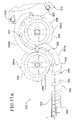
- FIG. 1is a front perspective view of a conventional plastic foam cup.
- FIG. 2is a cross-sectional side view of the conventional plastic foam cup of FIG. 1 .
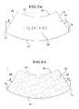
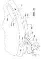
- FIG. 3is a front perspective view of one embodiment of a reinforced plastic foam cup disclosed herein.
- FIG. 4is a cross-sectional side view of the reinforced plastic foam cup of FIG. 3 .
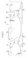
- FIG. 5is a top plan view of the outside face of one embodiment of a reinforcing member disclosed herein.
- FIG. 6is a bottom plan view of the inside face of the reinforcing member of FIG. 5 .
- FIG. 7is a top plan view of a plurality of reinforcing members sequentially positioned on an elongated release liner.
- FIG. 5Ais a top plan view of the outside face of an alternative embodiment of a reinforcing member disclosed herein.
- FIG. 6Ais a bottom plan view of the inside face of the reinforcing member of FIG. 5A .
- FIG. 7Ais a top plan view of a plurality of reinforcing members of FIG. 5A sequentially positioned on an elongated release liner.
- FIG. 5Bis a top plan view of the outside face of another alternative embodiment of a reinforcing member disclosed herein.
- FIG. 8is a schematic block diagram illustrating one embodiment of a method of manufacturing the reinforced plastic foam cup of FIG. 3 disclosed herein.
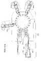
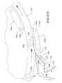
- FIG. 9is a diagrammatic top plan view of one embodiment of a cup reinforcing system disclosed herein, illustrating a pre-reinforced plastic foam cup separate from a reinforcing member.
- FIG. 10is a diagrammatic top plan view of the cup reinforcing system of FIG. 9 , illustrating the pre-reinforced plastic foam cup and the reinforcing member moving into an engagement position.
- FIG. 11is a cross-sectional side view of the separated pre-reinforced plastic foam cup and reinforcing member of FIG. 10 .
- FIG. 12is a diagrammatic top plan view of the cup reinforcing system of FIG. 9 , illustrating a centered vertical axis of the reinforcing member aligned with the tapered side wall of the pre-reinforced plastic foam cup.
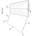
- FIG. 13is a side view of the pre-reinforced plastic foam cup aligned with the centered vertical axis of the reinforcing member.
- FIG. 14is a cross-sectional side view of the reinforcing member engaging the tapered side wall of the plastic foam cup.
- FIG. 15is a diagrammatic top plan view of the cup reinforcing system of FIG. 9 , illustrating a first portion of the reinforcing member attached to the cup and a second portion of the reinforcing member not attached to the plastic foam cup.
- FIG. 16is a side view of the partially attached reinforcing member of FIG. 15 .
- FIG. 17is a diagrammatic top plan view of the cup reinforcing system of FIG. 9 , illustrating the reinforcing member full attached to the plastic foam cup to form the reinforced plastic foam cup of FIG. 3 .
- FIG. 18Ais a diagrammatic top plan view of one embodiment of the cup reinforcing system disclosed herein.
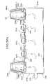
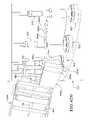
- FIG. 18Bis a diagrammatic side view of the cup reinforcing system of FIG. 18A .
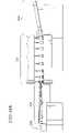
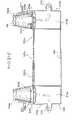
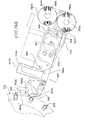
- FIG. 19is a side view of the dual cup dispenser, the cup conveyor and the vacuum chamber of one embodiment of the cup reinforcing system disclosed herein.
- FIG. 20is a front perspective view of one set of cup dispensing screws of the dual cup dispenser of FIG. 19 .
- FIG. 21is a top plan view of a set of cup dispensing screws of the dual cup dispenser engaging a cup.
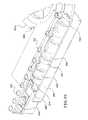
- FIG. 22is a front perspective view of the dual cup dispenser, the cup conveyor, the vacuum chamber and the spacing screw of one embodiment of the cup reinforcing system disclosed herein.
- FIG. 23is a partially cross-sectional perspective view of the vacuum chamber of FIG. 22 , illustrating the plurality of adjacent conveyor belts and the plurality of air inlets.
- FIG. 24Ais a schematic side view of the vacuum box of FIG. 22 , illustrating the flow of air from an area above the plurality of conveyor belts, entering the vacuum chamber via the plurality of air inlets and exiting the vacuum chamber via the air outlet.
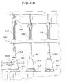
- FIG. 24Bis a schematic side view of an alternative embodiment of a vacuum box, illustrating the flow of air from an area above the plurality of conveyor belts, entering the vacuum chamber via the plurality of air inlets and exiting the vacuum chamber via a plurality of air outlets.
- FIG. 24Cis a schematic side view of an alternative embodiment of a vacuum box, illustrating the flow of air from an area above the plurality of conveyor belts, entering a plurality of air flow members via the plurality of air inlets and exiting the air flow members via a plurality of air outlets.
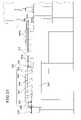
- FIG. 25is a side view of the spacing screw, the in-feed star wheels and a portion of the cup mover of one embodiment of the cup reinforcing system disclosed herein.
- FIG. 26is a front perspective view of one embodiment of a portion of the cup feeder, the spacing screw and a portion of an in-feed star wheel of one embodiment of the cup reinforcing system disclosed herein.
- FIG. 27Ais a top plan view of one embodiment of a portion of the cup feeder, the cup spacer illustrating the spacing screw and a plurality in-feed star-wheels and a portion of the cup mover.
- FIG. 27Bis a top plan view of an alternative embodiment of a portion of the cup feeder, the cup spacer illustrating the spacing screw and one in-feed star-wheel and a portion of the cup mover.
- FIG. 28is a front perspective view of the portion of the cup feeder, the cup spacer illustrating the spacing screw and the plurality in-feed star-wheels and the portion of the cup mover of FIG. 27A .
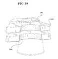
- FIG. 29is a cross-sectional side view of one of the cup pockets of one of the star-wheels of the cup reinforcing system disclosed herein.
- FIG. 30is a front perspective view of one of the in-feed star wheels and the cup mover of one embodiment of the cup reinforcing system disclosed herein illustrating a plurality of cup holders associated with a plurality of centering bells.
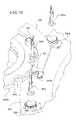
- FIG. 31Ais a side view of the in-feed star wheel and the cup mover of FIG. 30 , illustrating the cup mover positioned adjacent to and slightly below the in-feed star wheel.
- FIG. 31Bis a side view of the in-feed star wheel, the cup mover of FIG. 30 and a superstructure which supports the plurality of centering bells.
- FIG. 32is a front perspective view of the bottom member of one of the cup holding stations of the cup mover of one embodiment of the cup reinforcing system.
- FIG. 33is a side view of one embodiment of a centering bell of the cup holding station engaging a cup which is positioned on the bottom member of the cup holding station of the cup mover.
- FIG. 34is a front perspective view of one embodiment of a centering bell of a cup holding station of the cup mover.
- FIG. 35is a cross-sectional side view of one embodiment of a centering bell of the cup holding station engaging a cup which is positioned on the bottom member of the cup holding station of the cup mover.
- FIG. 36is a schematic block diagram of an electronic configuration of one embodiment of the cup reinforcing system disclosed herein.
- FIG. 37is a front perspective view of one embodiment of the cup remover of the cup reinforcing system disclosed herein.
- FIG. 38Ais a top plan view of one embodiment of the reinforcing member dispenser of the cup reinforcing system disclosed herein.
- FIG. 38Bis a top plan view of an alternative embodiment of a reinforcing member dispenser of the cup reinforcing system disclosed herein, illustrating an alternative design of a release liner slack accumulator.
- FIG. 39a front perspective view of the reinforcing member dispenser of FIG. 38A , illustrating the reinforcing member dispenser at an appropriate angle relative to the cup mover.
- FIG. 40an enlarged front perspective view of the reinforcing member dispenser of FIG. 38A , illustrating a portion of the reinforcing member dispenser interacting with the cups transported via the cup mover.
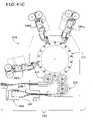
- FIG. 41Ais a diagrammatic top plan view of an alternative embodiment of the cup reinforcing system disclosed herein.
- FIG. 41Bis a diagrammatic top plan view of an alternative embodiment of the cup reinforcing system disclosed herein.
- FIG. 41Cis a diagrammatic top plan view of an alternative embodiment of the cup reinforcing system disclosed herein.
- FIG. 41Dis a diagrammatic top plan view of an alternative embodiment of the cup reinforcing system disclosed herein.
- FIGS. 42A to 42Eare perspective views of the interaction between the cup mover and the reinforcing member dispenser of one embodiment of the cup reinforcing system disclosed herein.
- FIGS. 43A to 43Fare diagrammatic top plan views of the cup reinforcing system disclosed herein, illustrating one embodiment of the attachment of a reinforcing member to a plastic foam cup.
- FIGS. 44A to 44Dare diagrammatic top plan views of an alternative embodiment of the cup reinforcing system disclosed herein.
- the present disclosurerelates in general to a reinforced drinking cup and more particularly to a disposable plastic foam reinforced drinking cup and a method of and apparatus for manufacturing the same.
- the reinforced drinking cupis particularly suitable for carrying or transporting hot beverages, such as coffee, tea and hot chocolate or other products.
- a reinforced plastic foam cup 30 of one embodiment disclosed hereinis formed from the process of reinforcing a base cup (such as a conventional plastic foam cup described above) with a reinforcing member as described below.
- the reinforcing cup 30includes a body 32 which defines an open top end 34 and a closed bottom end 36 , wherein the top end has a greater diameter than the bottom end.
- the bodyincludes a tapered side wall 38 that extends from the bottom end to the top end.
- the top end of the bodyincludes an outwardly formed lip 40 , however the cup does not need to have a formed lip.
- the plastic foam base cupmay be formed from any suitable material, such as beaded polystyrene.
- the base cupincludes a paper based cup suitably coated or otherwise laminated with one or more layers of polystyrene.
- a reinforcing member 42is attached to almost all of or a substantial portion of the outer surface of the tapered side wall 38 to provide increased tactile feel, support and rigidity to the tapered side wall.
- the tapered side wall 38 of the reinforced plastic foam cup 30includes a plastic foam layer 44 , a pressure sensitive adhesive layer 46 and a rigid material layer 48 which provides a better tactile feel.
- the reinforced plastic foam cup with the multi-layered tapered side walli.e., the plastic foam layer 44 , the adhesive layer 46 and the rigid material layer 48
- the reinforced plastic foam cupprovides a substantial increase in the tactile feel and rigidity of the reinforced plastic foam cup.
- the reinforced plastic foam cupprovides a disposable cup with the insulation properties of a plastic foam cup and also the tactile feel of a paper-based cup.
- Such reinforced plastic foam cupcosts less than a paper-based cup with comparable insulation properties (i.e., such as a nested paper-based cup).
- the reinforced plastic foam cupwhen graphics are printed on the outer face of the rigid material of the reinforcing member, the reinforced plastic foam cup further provides a disposable cup with the high-quality graphic presentation properties of a paper-based cup.
- a reinforcing member or reinforcer 42includes a body 50 formed from a malleable, rigid material, such as a suitable paper, a suitable plastic stock, a suitable composite material or any other suitable material.
- the body 50is substantially planar or flat with a thickness in the range 1.5 millimeters to 8.0 millimeters, and in one preferred embodiment a thickness in the range of approximately 2.7 millimeters to 4.0 millimeters.
- an inner face or surface 52 of the flat body 50 of the reinforcing member 42is completely or substantially completely coated with an adhesive and preferably a pressure sensitive adhesive 54 .
- any suitable adhesive or bonding agent which completely or substantially completely coats the inner face of the reinforcing membermay be employed.
- the adhesive coating of the reinforcing member 42is releasably attached to a suitable elongated release liner 56 which enables the reinforcing member to be handled without the adhesive exposed.
- a plurality of reinforcing members 42are sequentially positioned linearly along a single release liner 56 .
- the release liner 56may be made of any suitable material, such as a suitable plastic, paper or any combination thereof.
- the release lineris an approximately forty pound craft paper.
- an outer face or surface 58 of the flat body 50includes one or more suitable branding areas 60 where high quality graphics, such as a company's logo or suitable marketing graphics, text and/or images are printed thereon.
- a laminate material or a protective coating(not shown) is applied to the outer face over the layer(s) of ink to protect and/or enhance the printed matter.
- the flat body 50is defined by a curved or annular edge 62 , a curved or annular edge 64 , an angled front or leading edge 66 and an angled rear or trailing edge 68 .
- the edge 62 of the reinforcing memberis suitably concavely shaped and the edge 64 is suitably convexly shaped, wherein a trough of the concavely shaped edge and an apex of the convexly shaped edge reside in the same vertical plane.
- the length of the edge 62is less than the length of the edge 64 such that the leading edge 66 is angled offset from a vertical plane at a suitable angle (A degrees) and the trailing or rear edge 68 is also angled offset from a vertical plane at a suitable angle (B degrees).
- a sensing edge 70which includes a portion of the leading edge adjacent to edge 64 extends vertically or substantially vertically. As described in more detail below, the sensing edge is utilized in determining the exact location of the reinforcing member as well as preventing leakage of the adhesive when a plurality of reinforcing members releasably attached to a release liner are wound into a supply roll.
- the reinforcing memberin addition to a sensing edge 70 (i.e., a portion of the leading edge adjacent to edge 64 extending vertically or substantially vertically), the reinforcing member includes an adhesive relief edge 72 .
- the adhesive relief edgeis a vertically or substantially vertically extending portion of the trailing edge adjacent to edge 64 of the reinforcing member.
- the sensing edge and the adhesive relief edgeare the same length or substantially the same lengths.
- the sensing edge and the adhesive relief edgeare different lengths or substantially different lengths. It should be appreciated that the reinforcing members are displayed in an upside down position to match the upside down cups which they will engage with as described below. Accordingly, as best seen in FIG. 5B , the graphics 60 printed on the reinforcing member may printed in any suitable configuration.
- the sensing edge and the adhesive relief edgeeach redistribute the formed pressure from these respective points on the reinforcing member to an extended portion of the reinforcing member. This redistribution relieves the pressure which forms and thus reduces or prevents the leaking of the adhesive coating from one or more of the wound reinforcing members.
- the dimensions of the reinforcing memberwill be specific to the specifications of the base cup. Therefore, the respective angles of the leading and trailing edges of the reinforcing member, the shape of the top and bottom edges, the length between the leading edge and the trailing edge or any other suitable dimensions of the reinforcing member will be based on the size of the base cup, the angle of the tapered side wall of the base cup or any other specification of the base cup. It should be further appreciated that when the reinforcing member is initially attached to the cup, as described below, the sensing edge 70 is: (i) perpendicular or substantially perpendicular to the bottom edge of the cup; and (ii) parallel to the centered vertical axis of the reinforcing member. Such a configuration provides an absolute reference point for the cup reinforcing system to determine the location of the reinforcing member.
- the reinforcing memberis configured such that the angle between the concave edge and leading edge is approximately ninety degrees, the angle between the concave edge and trailing edge is approximately ninety degrees, the angle between leading edge and the sensing edge is approximately one-hundred-fifty degrees, the angle between the trailing edge and adhesive relief edge is approximately one-hundred-fifty degrees, the angle between the convex edge and the sensing edge is approximately one-hundred-twenty degrees, and the angle between the convex edge and the adhesive relief edge is approximately one-hundred-twenty degrees.
- the reinforcing memberis configured such that the angle between the concave edge and leading edge is approximately ninety degrees, the angle between the concave edge and trailing edge is approximately ninety degrees, the angle between leading edge and the sensing edge is approximately one-hundred-fifty-five degrees, the angle between the trailing edge and adhesive relief edge is approximately one-hundred-fifty-five degrees, the angle between the convex edge and the sensing edge is approximately one-hundred-fifteen degrees, and the angle between the convex edge and the adhesive relief edge is approximately one-hundred-fifteen degrees.
- the reinforcing memberis configured such that the angle between the concave edge and leading edge is approximately ninety degrees, the angle between the concave edge and trailing edge is approximately ninety degrees, the angle between leading edge and the sensing edge is approximately one-hundred-sixty degrees, the angle between the trailing edge and adhesive relief edge is approximately one-hundred-sixty degrees, the angle between the convex edge and the sensing edge is approximately one-hundred-ten degrees, and the angle between the convex edge and the adhesive relief edge is approximately one-hundred-ten degrees.
- the method or process of manufacturing the above-described reinforced plastic foam cupincludes determining a vertical axis which runs through a center point of the top and bottom edge of the reinforcing member as indicated in block 80 .
- the methodincludes positioning the base or pre-reinforced plastic foam cup upside-down and positioning the reinforcing member adjacent to the tapered side wall of the upside-down base cup at an angle which corresponds with the angle of the tapered side wall of the base cup as indicated in blocks 82 and 84 .
- the inside face of the reinforcing memberis attached to the outer face of the tapered side wall of the base cup along the determined centered vertical axis, wherein the reinforcing member is attached at an angle which corresponds with the angle of the tapered side wall of the base cup.
- the method or process of manufacturing or sequentially reinforcing at least one and preferably a plurality of individual plastic foam cupsincludes utilizing a processor controlled cup reinforcing system or apparatus 100 .
- the cup reinforcing systemincludes a cup conveyer system which moves the cup into the attachment position and transports or moves one or more base or pre-reinforced plastic foam cups 102 throughout the cup reinforcing system 100 in a conventional manner.
- the cup reinforcing systemfurther includes at least one reinforcing member dispenser 104 operable to sequentially feed each reinforcing member toward the attachment position for attachment to the individual base cup 102 .
- the cup reinforcing systemalso includes a suitable sensor 106 operable to determine the location of each reinforcing member, wherein based on such determined location, the cup reinforcing system 100 aligns a centered vertical axis 108 of the reinforcing member 42 with the tapered side wall of an individual base cup 102 .
- a system or apparatus for attaching a reinforcing member to a cupincludes a cup conveyor system, a reinforcing member dispenser (i.e., a device for centering and affixing or attaching the reinforcing member to the outer surface of the tapered side wall of the cup). It should be appreciated that any suitable cup reinforcing system may be implemented in accordance with the disclosed process of reinforcing a plastic foam cup
- the cup conveyerincludes one or more individual cup positions wherein each individual cup position includes a rotationally mounted cup holding turntable with a suitable cup positioning device to suitable position the cup at a set position on the cup holding turntable.
- the cup holding turntableis also operable to rotate the cup a full 360 degrees in clockwise and counterclockwise directions.
- the cup positioning deviceincludes a frictional engagement member or mandrel which frictionally engages the inner face of the wall of the base cup to fix the cup in the suitable position on the turntable.
- a base cup 102is placed face down (i.e., resting on the open top end) on the cup conveyer system and the cup is moved into a position that facilitates engagement with the reinforcing member.
- the reinforcing member dispenser 104is operable (via one or more suitable rollers 110 ) to feed the reinforcing member in the direction of a face down base cup.
- the reinforcing member dispenser 104is configured or shaped to define or include a release liner separation section 112 . In this embodiment, based on the orientation of the reinforcing member 42 relative to the release liner separation section 112 , the reinforcing member 42 will separate from the release liner 56 (which protects the pressure sensitive adhesive) when the reinforcing member is fed through the release liner separation section 112 .
- the cup reinforcing systemalso includes one or more reinforcing member application pad(s) 114 which operate to guide the reinforcing member and prevent the reinforcing member from shifting positions after a portion of the reinforcing member 42 separates from the release liner 56 .
- the reinforcing member dispenseris operable to feed the release liner 56 (which the reinforcing member is releasably attached to) toward the base cup 102 at a suitable angle offset from a vertical plane which corresponds with the angle (also offset from a vertical plane) of the tapered side wall of the base cup.
- the reinforcing member 42when the reinforcing member 42 separates from the release liner 56 , the reinforcing member will be positioned at a suitable angle which corresponds with the angle of the tapered side wall of the base cup 102 .
- the reinforcing memberengages the tapered side wall of the base cup at a suitable angle offset from a vertical plane while both the cup and the reinforcing member are moving. As described in more detail below, such angling provides that the reinforcing member will completely adhere to the tapered side wall of the base cup.
- the cup reinforcing systemalso includes at least one sensor 106 for determining or verifying the location or position of the reinforcing member 42 relative to the position of the base cup 102 .
- the sensordetects the location of the substantially vertical portion or sensing edge 70 of the front or leading edge of the reinforcing member 42 to determine the relative position of the reinforcing member.
- the processor of the cup reinforcing systemdetermines or calculates when the reinforcing member 42 is moved into a position in which a centered vertical axis 108 of the reinforcing member 42 is aligned with the tapered side wall of the base cup 102 .
- the centered vertical axis 108is the vertical axis that runs through both the trough of the concavely shaped top edge 62 of the reinforcing member and the apex of the convexly shaped bottom edge 64 of the reinforcing member.
- At least one sensoris positioned or placed such that the sensor detects the exact location of each reinforcing member immediately prior to that reinforcing member being affixed to a base cup.
- positioning the sensor at such a positionprovides for increased accuracy in the placement of the reinforcing member on the base cup which, as described in more detail below, provides for a proper engagement between the reinforcing member and the cup.
- the alignment processis controlled by suitable timing mechanisms wherein one or more sensors are utilized to verify that the timing mechanisms are correct.
- the sensorsenses the sensing edge.
- the sensorcould sense another suitable reinforcing member position indicator.
- the processor of the cup reinforcing systemcauses the cup conveyer to move the cup 102 into the attachment position and causes the reinforcing member dispenser 104 to feed the reinforcing member 42 into the attachment position where the centered vertical axis 108 of the reinforcing member 42 is aligned with the tapered side wall of the base cup 102 , and causes the inner face 52 of the reinforcing member 42 (which is completely or substantially completely coated with a pressure sensitive adhesive 54 ) to be initially attached to the tapered side wall of the cup along the centered vertical axis (as best seen in FIG. 13 ).
- both the cup and the reinforcing memberare moving prior to and through the point of attachment of the reinforcing member to the outer surface of the tapered side wall of the cup.
- the cup conveyermoves the base cup into a position which engages the reinforcing member application pad 114 , such that the tapered side wall of the cup presses against or engages the reinforcing member application pad to cause the reinforcing member 42 (which is positioned between the tapered side wall and the reinforcing member application pad 114 ) to engage the tapered side wall of the cup 102 as best seen in FIG. 14 .
- the reinforcing member 42is situated at an angle which corresponds with the angle of the tapered side wall of the cup and thus the reinforcing member is attached to the base cup at an angle which corresponds with the angle of the wall of the base cup. Moreover, as seen in FIG. 13 , after the reinforcing member is initially attached to the cup along the centered vertical axis of both the reinforcing member and the cup, the leading edge 66 and trailing edge 68 of the reinforcing member remain unattached or are otherwise free.
- the top edge 62 of the reinforcing memberadheres to the tapered side wall at (or substantially adjacent to) the bottom end of the cup and the bottom edge 64 of the reinforcing member adheres to the tapered side wall at (or substantially adjacent to) the top, open end of the cup.
- the reinforcing membermay be attached to the cup slightly offset from the centered vertical axis of the reinforcing member, and in one embodiment in a range of plus or minus three degrees.
- the cup reinforcing system 100is operable to cause the remaining unattached portions of the reinforcing member to engage and attach to the tapered side wall of the cup.
- the cuprotates 180 degrees in a first direction.
- the tapered side wall of the cup 102presses against or engages the reinforcing member application pad 114 to cause a first portion or section of the reinforcing member to engage and thus, due to the pressure sensitive adhesive coating 54 on the reinforcing member 42 , attach to the tapered side wall of the cup.
- the first portion or sectionincludes the portion of the reinforcing member 42 which extends from the centered vertical axis 108 to the trailing edge 68 . Accordingly, as seen in FIG. 16 , after the first section of the reinforcing member is attached to the tapered side wall of the cup, a second section of the reinforcing member remains unattached or is otherwise free.
- the cupis then rotated 360 degrees in an opposite, second direction.
- the tapered side wall of the cuppresses against or engages the reinforcing member application pad 114 to cause the second portion or section of the reinforcing member to engage and attach to the tapered side wall of the cup.
- the second portion or sectionincludes the portion of the reinforcing member 42 which extends from the centered vertical axis to the leading edge.
- the shape or configuration of the reinforcing member coupled with the shape or configuration of the cupprovides that as the remaining portions of the reinforcing member are attached to the cup, the reinforcing member will affix to the tapered side wall of the cup in the desired configuration (i.e., the cup pulls to the reinforcing member and the reinforcing member pulls to the cup).
- the reinforced plastic foam cupprovides a disposable drinking cup with the insulation properties of a plastic foam cup and the tactile feel and high quality graphic printing properties of a paper-based cup to provide an enhanced drinking experience for a person.
- the cup reinforcing systemmay be configured with a plurality of reinforcing member application pads which are positioned on opposite sides of the cup such that the cup is rotated 180 degrees in a first direction to attach the first portion of the reinforcing member to the cup, followed by rotating the cup 180 degrees in the second direction to attach the second portion of the reinforcing member to the cup. After the rotation in the second direction, the reinforcing member is completely adhered to the base cup and the reinforced plastic foam cup 30 described above (and illustrated in FIGS. 3 and 4 ) is formed. It should be appreciated that any suitable apparatus for or method of attaching the reinforcing member to the tapered side wall along the centered vertical axis may be implemented in accordance with the present disclosure.
- the cup reinforcing systemis operable to sequentially reinforce one or more individual cups.
- one or more cupsare each placed face down and suitably spaced apart on the cup conveyer.
- one or more reinforcing membersare positioned linearly along a single release liner and wrapped in a supply roll. The supply roll is threaded about the reinforcing member dispenser to provide a continuous feed of reinforcing members.
- the cupis placed on the cup conveyer resting on its closed bottom end.
- the reinforcing member dispenseris positioned such that the reinforcing member engages the tapered side wall of the cup situated in a vertical plane.
- the cup conveyeris configured at a suitable angle to provide that the tapered side wall of the cup engages the reinforcing member in the vertical plane as well.
- the cup conveyeris suitably angled and the cup is transported throughout the cup reinforcing system at such an angle.
- the reinforcing member dispenser and/or the reinforcing member application padsare accordingly adjusted to any suitable angle to account for the angle of the cup and/or reinforcing member to insure that the reinforcing member is initially affixed to the tapered side wall of the cup at an angle which corresponds with the tapered side wall of the cup.
- the cup reinforcing system 200generally includes a cup conveyor system 202 and one or more reinforcing member dispensers 204 a and 204 b (referred to generally as 204 ).
- the cup conveyor systemis configured to receive each pre-reinforced cup, transport and space such received cups into an appropriate position for attachment of a reinforcing member and remove each cup from the cup reinforcing system after the attachment of a reinforcing member to that cup.
- Each reinforcing member dispenser 204is configured to transport each reinforcing member into the appropriate position for attachment with the transported cups and attach each reinforcing member, along a centered vertical axis of the reinforcing member, to the wall of one of the upside down positioned cups at an angle which corresponds with the angle of the tapered side wall of the cup.
- the cup conveyor systemincludes a cup dispenser 206 , a cup feeder 208 , a cup spacer 210 , a cup mover 212 , and a cup remover 214 .
- the processor 402 of the cup reinforcing systemis in communication with and programmed to control the cup dispenser 206 , the cup feeder 208 , the cup spacer 210 , the cup mover 212 , the cup remover 214 , and the reinforcing member dispenser 204 .
- the processoris also in communication with and programmed to control at least one input device or control panel 404 , such as a touch screen or one or more suitable switches or buttons, for enabling a user to operate the cup reinforcing system and at least one display device 406 for displaying suitable information to a user of the cup reinforcing system.
- the input deviceenables a user to input appropriate commands and/or suitable information to the processor of the cup reinforcing system.
- a userutilizes at least one input device to initiate and shut-off the cup reinforcing system, provide information regarding the exact specifications of the cups and/or reinforcing members, input the speed to move the cups throughout the cup reinforcing system, and input the angle to set the reinforcing member dispenser relative to the cup mover.
- one or more of the functions described abovemay be manually adjusted utilizing one or more mechanical or other suitable devices.
- the angle to set the reinforcing member dispenser relative to the cup movermay be manually adjusted utilizing one or more individual hand cranks.
- the processoris in communication with or operable to access or to exchange signals with at least one data storage or memory device 408 .
- the memory devicestores program code and instructions, executable by the processor, to control the cup reinforcing system.
- the memory deviceincludes random access memory (RAM), which can include non-volatile RAM (NVRAM), magnetic RAM (MRAM), ferroelectric RAM (FeRAM) and other forms as commonly understood in the art.
- RAMrandom access memory
- NVRAMnon-volatile RAM
- MRAMmagnetic RAM
- FeRAMferroelectric RAM
- the memory deviceincludes read only memory (ROM).
- the memory deviceincludes flash memory and/or EEPROM (electrically erasable programmable read only memory). Any other suitable magnetic, optical and/or semiconductor memory may operate in conjunction with the cup reinforcing system disclosed herein.
- part or all of the program code and/or operating data described abovecan be stored in a detachable or removable memory device, including, but not limited to, a suitable cartridge, disk, CD ROM, DVD or USB memory device.
- the processor and memory devicemay sometimes be collectively referred to herein as a “computer” or “controller.”
- a pre-reinforced or base cupenters the cup reinforcing system via the cup dispenser 206 from a supply of nested cups.
- the cuptravels via the cup feeder 208 to the cup spacer 210 and then to the cup mover 212 .
- the cup mover 212aligns the cup into the appropriate alignment with the reinforcing member dispenser 204 and the reinforcing member is attached or affixed to the cup by the reinforcing member dispenser 204 .
- the reinforced cupis removed from the cup reinforcing system via the cup remover 214 .
- any other suitable cup conveyor system and any suitable reinforcing member dispenserwhich attaches a reinforcing member to the tapered side wall of a base cup along the centered vertical axis of the reinforcing member and subsequently attaches the remaining portions of the reinforcing member to the tapered side wall of the base cup may be implemented in accordance with the cup reinforcing system disclosed herein.
- the cup dispenser 206 of the cup reinforcing systemincludes a frame 230 which supports two independent, offset guide members 232 a and 232 b (referred to generally as 232 ).
- Each guide memberis configured to hold a stack of nested pre-reinforced or base cups 234 a and 234 b (referred to generally as 234 ) in upside down positions above the cup feeder 206 .
- Each guide member 232is associated with at least one and preferably a plurality of or set of vertically or substantially vertically disposed co-acting cup dispensing screws or cup de-nesters 236 a , 236 b , 236 c and 236 d (referred to generally as 232 and as best seen in FIGS. 20 and 21 ) made of any suitable smooth surfaced, non-abrasive material with self-lubrication properties, such as any suitable plastic, for example a DELRIN® plastic manufactured by E. I. DU PONT DE NEMOURS AND COMPANY.
- Each cup dispensing screw 236has internally extending threading 238 on its outer surface.
- the threadsare suitably sized and angled to correlate to the top lips of the upside down positioned base cups 102 held by the guide members 232 .
- the cup dispensing screws 236are each movably connected or coupled to at least one actuator 240 , such as a motor or other suitable movement generating device controlled by the cup reinforcing system processor which causes each cup dispensing screw 236 to rotate in the appropriate direction at a suitable speed.
- each rotating cup dispensing screw 236engages a portion of the outwardly extending lip 24 of a first nested upside down cup held by one of the guide members 232 .
- Each cup dispensing screwrotates to pull the first cup, via the top threading 238 a of each cup dispensing screw which engages the cup lip 24 , from the nested set of cups 234 .
- the cup lip 24 of the first cupis passed to the threading located at or near the middle 238 b of each rotating cup dispensing screw and then to the threading located at or near the bottom 238 c of each rotating cup dispensing screw to slowly and consistently pull the first cup further away from the nested set of cups 234 .
- the top threading 238 aengages the lip 24 of a second nested upside down cup to pull the second cup, via the top threading 238 a engaging the lip of the second cup, from the nested set of cups 234 .
- each separated cup 102proceeds to drop down to the cup feeder 208 located directly below the cup dispenser 206 .
- the cup dispenserincludes more than two independent, offset guide members.
- each guide memberholds a stack of nested pre-reinforced cups and is further associated with at least one and preferably a plurality of vertically disposed cup dispensing screws as described above.
- one guide memberis configured to hold a plurality of stacks of nested pre-reinforced cups above a plurality of different locations of the cup feeder.
- the guide memberis associated with at least one and preferably a plurality of vertically disposed cup dispensing screws for each held stack of pre-reinforced cups.
- one guide memberis configured to hold one stack of nested pre-reinforced cups above a single location of the cup feeder.
- the guide memberis associated with at least one and preferably a plurality of vertically disposed cup dispensing screws for the held stack of pre-reinforced cups.
- any suitable apparatus or method for loading one or more pre-reinforced cups onto the cup feedermay be implemented in accordance with the cup reinforcing system disclosed herein.
- the cup dispenser disclosed hereinmay be located at any suitable position upstream from the reinforcing member dispenser described below.
- the cup feeder 208 of the cup conveyor systemincludes a frame 250 which supports a plurality of rows of adjacently positioned conveyor belts 252 a to 252 e (referred to generally as 252 ).
- the conveyor beltsare suitably movably connected or coupled to at least one actuator, such as a motor or other suitable movement generating device 254 which causes the conveyor belts to move at any suitable speed in a conventional manner.
- one, more or each of the conveyor belts 252define one or more apertures or holes 256 through which air flows as described below.
- the conveyor belts which are positioned or aligned beneath or under the offset guide members 232 a and 232 bin this case conveyor belts 252 a and 252 e , define larger diameter apertures or holes 256 a than the apertures or holes 256 b of the conveyor belts which are not positioned under the offset guide members, in this case conveyor belts 252 b , 252 c and 252 d .
- any suitable number of holes, of any suitable diameter and of any suitable shapesuch as elongated oval shaped holes) which allows an adequate amount of air flow as described below, may be implemented in accordance with the cup reinforcing system disclosed herein.
- the frame 250 of the cup feeder 208supports a vacuum chamber, box or housing 258 .
- the vacuum box 258includes a top wall or surface 260 and a spaced apart bottom wall or surface 262 .
- the top walldefines a plurality of apertures or air inlets 264 .
- the vacuum boxincludes spaced apart side walls 268 , wherein the top of each side wall is connected to the top wall and the bottom of each side wall is connected to the bottom wall.
- the vacuum boxalso includes spaced apart end walls 270 a and 270 b , wherein the top of each end wall is connected to the top wall, the bottom of each end wall is connected to the bottom wall, one side of each end wall is connected to one side wall and the other side of each end wall is connected to the other side wall.
- At least one side wall of the vacuum box(side wall 270 a of FIG. 24A and side walls 270 a and 270 b of FIG. 24B ) each defines one or more apertures or air outlets 272 which are connected, via suitable air communication lines, to one or more vacuum or negative pressure sources (not shown). That is, the vacuum chamber is in fluid communication with a suitable vacuum or negative pressure source.
- the frame 250 of the cup feederincludes two air flow members 274 a and 274 b spaced below the offset guide members of the cup dispenser.
- each air flow memberis connected to a vacuum or negative pressure source which pulls each base cup from the cup dispenser. It should be appreciated that in this embodiment, air only flows through the larger diameter holes in the conveyor belt (located directly above the air flow member) and not through the smaller diameter holes, if any, in the conveyer belt not located directly above the air flow member.
- the vacuum sourceprovides negative air flow from the area above the conveyer belts 252 , through the holes 264 of the conveyer belts, the air inlets 256 of the top surface 260 of the vacuum box and the defined air outlet 272 of the vacuum box to the vacuum source.
- each separated base cupis pulled downwardly by the vacuum pressure, in a face down position, from the cup dispenser 206 onto the cup feeder 208 .
- the cup reinforcing systemis configured to move the cups along the conveyor belts at a relatively slow speed when compared to the speeds which bottles are moved though a bottle labeling system. That is, while bottles of a bottle labeling system are typically labeled at approximately one-thousand bottles per minute, the disclosed cup reinforcing system applies reinforcing members to base cups at less than half the rate of such bottle labeling systems. As mentioned above, such a reduction in the speed which the cups are moving through the cup reinforcing system eliminates static electricity buildup often caused by rapid movement of plastic foam cups.
- the cup feeder 208includes at least two opposing spaced-apart elongated guide rails or guide tracks 266 a and 266 b (referred to generally as 266 ) supported by the frame 250 of the cup feeder.
- the guide rails 266are angled offset from a vertical plane at a suitable angle to match the angle of the tapered side walls of the cups transported by the conveyor belts 252 .
- Guide rail 266 a and 266 bextend in intersecting planes such that the space between the two guide rails 266 is reduced as the guide rails extend out from an area substantially below the cup dispenser 206 .
- each cup 102moves along the conveyor belts 252 of the cup feeder 208 in the direction of the cup spacer 210 , each cup engages one of the guide rails 266 . As the cups move closer to the cup spacer, the engagement with the guide rails 266 causes the cups to move into a single-file order.
- the cup feedermay include any suitable apparatus or method for transporting the cups from the cup dispenser to the cup spacer.
- the cup spacer 210 of the cup conveyor systemincludes a frame 280 positioned adjacent to and at substantially the same height as the cup feeder 208 .
- the frame of the cup feedersupports an in-feed screw or spacing screw 282 and two co-acting inlet stars or in-feed star-wheel conveyors 284 a and 284 b (referred to generally as 284 ).
- the frame of the cup feedersupports an in-feed screw or spacing screw 282 and one inlet star or in-feed star-wheel conveyor 284 a .
- the cup spacer 210is utilized to transport the each cup 102 from the cup feeder 208 to the cup mover 212 .
- the in-feed screw or spacing screw 282 of the cup spacer 210is a horizontally or substantially horizontally disposed member made of any suitable smooth surfaced, non-abrasive material with self-lubrication properties, such as any suitable plastic, for example a DELRIN® plastic manufactured by E. I. DU PONT DE NEMOURS AND COMPANY.
- the spacer screwhas internally extending threading 286 on its outer surface. The threading 286 is suitably sized and angled to correlate to the tapered side wall of the cups. As seen in FIGS.
- the space between the threads of the spacer screwgradually and consistently increase from a first end 294 of the spacer screw adjacent to the cup feeder 208 to a second end 296 of the spacer screw adjacent to the cup mover 212 .
- the increased spacing between the spacer screw threadsprovides that as each cup 102 is transported from the first end 294 of the spacer screw to the second end 296 of the spacer screw, each cup (which is engaged by a portion of the threading of the spacer screw) is suitably spaced apart.
- Such spacing of the cupscorresponds to the spacing between each pocket 290 of the first in-feed star wheel 284 a .
- the in-feed screw or spacing screw 282sequentially separates, regaps or spaces the single-file cups transported by the conveyor belt 252 to establish a separation distance that corresponds to the spacing between the pockets 290 of the first in-feed star-wheel 284 a . That is, the spacer screw 282 delivers, at the correct intervals, each cup into one of the pockets 290 of the first in-feed star-wheel 284 a . It should be appreciated that due to the direction of rotation of the spacer screw 282 , a cup may be slightly lifted off the conveyor belt as that cup is transported form the first end 294 of the spacer screw to the second end 296 of the spacer screw.
- a hold down member 298such as a bar made of any suitable smooth surfaced, non-abrasive material with self-lubrication properties, such as any suitable plastic, for example a DELRIN® plastic manufactured by E. I. DU PONT DE NEMOURS AND COMPANY, is supported by the frame 280 of the cup spacer 210 .
- any suitable plasticfor example a DELRIN® plastic manufactured by E. I. DU PONT DE NEMOURS AND COMPANY
- the spacer screwis movably connected or coupled to at least one actuator 288 , such as a motor or other suitable movement generating device controlled by the cup reinforcing system processor which causes the spacer screw to rotate in any suitable direction at any suitable speed in a conventional manner.
- actuator 288such as a motor or other suitable movement generating device controlled by the cup reinforcing system processor which causes the spacer screw to rotate in any suitable direction at any suitable speed in a conventional manner.
- Each inlet star 284 of the cup spacer 210is a horizontally or substantially horizontally disposed circular or substantially circular member made of any suitable smooth surfaced, non-abrasive material with self-lubrication properties, such as any suitable plastic, for example a DELRIN® plastic manufactured by E. I. DU PONT DE NEMOURS AND COMPANY.
- Each inlet star 284defines a plurality of pockets 290 suitable spaced around the circumference of that inlet star. The number of pockets is determined based on the size of the cups and the size of the reinforcing members.
- Each pocket 290is configured to hold or otherwise engage a cup 102 as the cup is transferred from the cup feeder 208 to the cup mover or turntable 212 .
- Each inlet staris movably connected or coupled to at least one actuator (not shown), such as a motor or other suitable movement generating device controlled by the cup reinforcing system processor which causes that inlet star to move in any suitable direction at any suitable speed in a conventional manner.
- actuatorsuch as a motor or other suitable movement generating device controlled by the cup reinforcing system processor which causes that inlet star to move in any suitable direction at any suitable speed in a conventional manner.
- the frame 280 of the cup spacersupports two inlet star guide members or guide rails 292 a and 292 b (referred to generally as 284 ).
- Guide rail 292 ais located adjacent to inlet star 284 a and guide rail 292 b is located adjacent to inlet star 284 b .
- Each guide rail 292prevents the cups transported by the inlet stars 284 from becoming displaced, such as by tipping over.
- the cup guide membersare suitable sized and suitable angled offset from a vertical plane to correlate to the cups.
- each cup 102is transported from at or near the second end 296 of the spacer screw 282 to a first pocket 290 of the first inlet star 284 a .
- the first inlet star 284 atransports the cup to a second pocket of the second inlet star 284 b .
- the second inlet star 284 btransports the cup, along a horizontally-disposed cup support member 297 , to a cup holding station 302 of the cup mover 212 as described below. That is, the pockets of the second inlet star 284 b and guide rail 292 b co-act to hold a cup in the proper position and place the cup onto one of the cup holding stations 302 of the cup mover. It should be appreciated that any suitable means or manner for transporting one or more cups from the cup dispenser to the cup mover or turntable may be employed in accordance with the cup reinforcing system disclosed herein.
- each star-wheel pocket 290is configured to prevent damaging the relatively fragile surface of the base cups.
- the star-wheel pockets 290 of the cup spacer 210 of the cup reinforcing system disclosed hereinis designed to handle the relatively fragile plastic foam cups.
- the cup mover or turntable 212 of the cup conveyor systemis rotatably supported by a suitable frame 300 positioned adjacent to the cup spacer 210 and at a height slightly below the cup spacer 210 .
- the turntableis a horizontally or substantially horizontally disposed cylindrical or substantially cylindrical member made of any suitable smooth surfaced, non-abrasive material with self-lubrication properties, such as any suitable plastic, for example a DELRIN® plastic manufactured by E. I. DU PONT DE NEMOURS AND COMPANY.
- the turntable 212is movably connected or coupled to at least one actuator, such as a motor or other suitable movement generating device which causes the turntable to move in any suitable direction at any suitable speed in a conventional manner. In operation, as described above, the cup mover 212 transports each base cup toward the attachment position adjacent to a reinforcing member dispenser 204 .
- the cup mover 212includes a plurality of individual rotary cup plates or cup holding stations 302 a , 302 b , 302 c and 302 d (referred to generally as 302 ) positioned uniformly around the periphery of the cup spacer.
- Each cup plate or holding station 302is configured to receive a cup 102 from a pocket 290 of the second inlet star 284 b .
- each cup holding stationincludes a rotational base 303 operable to rotate a full 360 degrees in clockwise and counterclockwise directions.
- each cup holding stationis spring loaded and operable to rise to engage the cup transported from the cup spacer and lower to disengage the cup from the cup mover after a reinforcing member has been applied to the cup.
- Each cup holding stationincludes a plurality of suitably shaped and sized walls which frictionally engage the walls of the cup to fix the cup in the suitable position on the cup holding station.
- the cupis held in place by a spring biased centering bell 312 .
- Each centering bellis operable to rotate a full 360 degrees in clockwise and counterclockwise directions. It should be appreciated that any suitable manner of holding the cup which provides that the tapered side wall of the cup is free for application of the reinforcing member may be implemented in accordance with the cup reinforcing system disclosed herein.
- each centering bell 312is supported from a rotatable superstructure 324 .
- the rotatable superstructureincludes a cam 326 and a plurality of spring loaded members 328 suitably connected to the plurality of centering bells 312 .
- the spring loaded membersare each movably connected or coupled to at least one actuator, such as a motor or other suitable movement generating device which causes each of the spring loaded members to move in any suitable direction at any suitable speed in a conventional manner.
- each spring located memberIn operation, as the plurality of spring loaded members 328 rotate about the cam 326 , the shape of the cam causes each spring located member to coil or retract which causes each centering bell to extend to engage a plurality of the walls of the cup or retract to disengage the plurality of walls of the cup.
- the spring mounted pressure of the centering bellsengages the cups with at least enough force to hold the cup as the cup is rotated and with less force than would damage the relatively fragile foam cup. It should be appreciated that any suitable mechanism or mechanisms which cause the centering bells to engage and disengage a plurality of walls of the cup may be implemented in accordance with the cup reinforcing system disclosed herein.
- each cup holding station 302is suitably beveled and tapered to match and engage the taper of the inner side wall of the top portion of the base cup 102 .
- each cup holding station 302includes a vertically disposed sidewall or cup support 304 , a horizontally disposed first wall 306 connected to the sidewall, a vertically disposed second wall 308 connected to the first wall and a beveled third wall 310 connected to the second wall.
- the first wall 306 of the cup holding stationengages the top 330 of the formed lip of the upside down cup and the second wall 308 of the cup holding station engages a top portion 332 of the inner surface of the upside down cup.
- any suitable engagement surfacewhich creates a male-female connection between the cup holding station and the cup may be implemented with the cup reinforcing system disclosed herein.
- the turntableis positioned slightly below the cup spacer.
- Such positioning of the cup mover below the cup spacerallows each transported cup to be placed directly on top of one of the cup holding stations 302 of the cup mover 212 . That is, to account for the height of the vertically disposed second wall 308 of the holding stations 302 when transporting each cup 102 from the cup spacer 210 to the cup holding stations 302 of the turntable 212 , the turntable is positioned slightly below the cup spacer.
- the walls of the centering bellare suitably configured to match and engage a plurality of the walls of the cup.
- a first wall of the centering bell 314engages the bottom rim 334 of the cup and a beveled or tapered second wall of the centering bell 316 engages the beveled or tapered inner side wall 336 of the cup.
- a third wall of the centering bell 318engages the outer bottom wall 16 of the cup
- a fourth wall of the centering bell 320engages the top surface of a centered raised portion 337 of the outer bottom wall of the cup
- a fifth wall of the centering bell 322engages the side wall 338 of the centered raised portion of the outer bottom wall of the cup.
- the turntable of the cup reinforcing systemwhen compared to a turntable of known bottle labeling devices, includes a reduced number of holding stations to accommodate the length of the reinforcing member. That is, since the reinforcing members applied to the base cups are of greater length than the labels applied to the bottles of a bottle labeling machine and such greater length may cause interferences when the reinforcing member is partially attached to the cups as described below, a greater distance must be between each holding station/centering bell of the turntable. Accordingly, providing a greater distance between each holding station/centering bell of the turntable without increasing the size of the turntable requires a reduction in the number of holding stations/centering bells of the turntable.
- each reinforcing member application pad 390includes a base 392 a and 392 b (referred to generally as 392 ) and a reinforcing member engaging surface 394 a and 394 b (referred to generally as 394 ), wherein the reinforcing member engaging surface includes any suitable material with anti-adhesion properties, such as a polytetrafluoroethylene or Teflon® coated tape, which resists adherence by the adhesive coated on the reinforcing member.
- Each reinforcing member application pad 390is positioned relative to the reinforcing member point of attachment to provide a suitable surface which is engaged by the tapered side wall of the cup to secure the reinforcing member (which is positioned between the tapered side wall of the cup 102 and the engaging surface 394 of the reinforcing member application pad 390 ) to the tapered side wall of the cup.
- Each reinforcing member application pad 390is suitably shaped and sized to accommodate the size and shape of the cups which are reinforced as well as to accommodate the size of the cup mover 212 which is moving the cups.
- each reinforcing member application pad 390is suitably beveled and tapered to match and engage the tapered side wall of the cup. It should be appreciated that the height or angle of one or more reinforcing member application pads may be suitable adjusted to accommodate the shape and size of the cups.
- the cup mover 212is configured to transport each base cup into a reinforcing member point of attachment or engagement or attachment position. At this point of attachment, a reinforcing member, dispensed from the reinforcing member dispenser 204 described below, is suitable partially attached to the tapered side wall of the cup 102 .
- the cup mover 212transports each reinforced cup to a cup remover 214 .
- the cup remover 214 of the cup conveyor systemincludes a frame 340 positioned adjacent to and at substantially the same height as the cup mover 212 .
- the frame 280 of the cup feedersupports two co-acting inlet stars or in-feed star-wheel conveyors 342 a and 342 b (referred to generally as 342 ), an out-feed conveyor device 344 and a reinforced cup exhaust device 346 .
- the cup reinforcing systemincludes one outlet star or out-feed star-wheel which transports the cups from the cup mover to the out-feed reinforced cup conveyor device.
- each outlet star 342is movably connected or coupled to at least one actuator, such as motor or other suitable movement generating device controlled by the cup reinforcing system processor which causes the outlet star to rotate or move in any suitable direction at any suitable speed in a conventional manner.
- each outlet star 342includes a plurality of pockets 346 on its circumference. Each pocket 346 is configured to hold a cup 102 as the cup is transferred from the cup mover 212 .
- the sidewall of each pocket 246is angled offset from a vertical plane at a suitable angle to match the angle of the tapered side walls of the base cups.
- the frame 340 of the cup remover 212supports two outlet star guide members or guide rails 348 a and 348 b (referred to generally as 348 ).
- Guide member 348 ais located adjacent to outlet star 342 a and guide member 348 b is located adjacent to outlet star 342 b .
- Each guide member 348prevents the cups transported by their respective outlet star 342 from becoming displaced, such as by tipping over.
- the cup guide members 348are sized and angled offset from a vertical plane to correlate to the specifications of the reinforced cups.
- the cup reinforcing systemincludes a plurality of inlet stars or in-feed star-wheels which co-act to transport the cup from the cup mover 212 to the out-feed cup conveyor device 344 .
- the out-feed cup conveyor device 344is suitably movably connected or coupled to at least one actuator, such as a motor or other suitable movement generating device which causes the conveyor belts to move at any suitable speed in a conventional manner.
- the cup removerincludes at least two opposing spaced-apart elongated guide rails or guide tracks 350 supported by the frame 340 of the cup remover.
- the guide rails 350are angled offset from a vertical plane at a suitable angle to match the angle of the tapered side walls of the cups transported by the out-feed cup conveyor device 344 .
- each cup 102is transported, via the out-feed reinforced cup conveyor device 344 , to a cup positioner 352 , such as a cup tipper or other suitable member, which positions or tips the reinforced cup onto its side (downside leading).
- a cup positioner 352such as a cup tipper or other suitable member, which positions or tips the reinforced cup onto its side (downside leading).
- the guide rails 350insure that the tipped cup is positioned on its side.
- the tipped cupis then vacuum pulled via the cup exhaust system 346 (not shown) to a stack of nested reinforced cups.
- any suitable means or manner for transporting one or more cups from the cup dispenser to the cup mover or turntablemay be employed in accordance with the cup reinforcing system disclosed herein.
- each reinforcing member dispenser 204 of the cup reinforcing systemincludes a frame 360 which supports an adjustable base or support 386 .
- the reinforcing member dispenser 204is operable to feed each reinforcing member 42 toward a cup 102 at a suitable angle offset form a vertical plane which corresponds with the angle (also offset from a vertical plane) of the tapered side wall of the cup.
- the adjustable base 386 of the reinforcing member dispenser 204is suitably angled offset from a vertical plane. The angle which the adjustable base 386 of the reinforcing member dispenser 204 is at may be adjusted (via a suitable angle adjustment mechanism 382 ) to accommodate for different base cups with different angled tapered side walls.
- the height of the adjustable base 386 of the reinforcing member dispenser 204may be adjusted (via a suitable height adjustment mechanism 384 ) to accommodate for different sized cups and variances in different reinforcing members positioning on the liner.
- the angle which the adjustable base 386 of the reinforcing member dispenser 204 is atmay be adjusted offset from a horizontal plane if necessary.
- the reinforcing member dispensermay be individually adjusted in three separate planes to facilitate a proper attachment of a reinforcing member to the tapered sidewall of a cup.
- the reinforcing member dispensermay be adjusted to any suitable angle in any suitable plane or number of planes to facilitate a proper attachment of a reinforcing member to the tapered sidewall of a cup.
- the reinforcing member dispenserincludes two reinforcing member supply holders 362 a and 362 b (referred to generally as 362 ) supported by the adjustable base 386 .
- Each reinforcing member supply holder 362is configured to hold a supply 364 a and 364 b (referred to generally as 364 ) of reinforcing members, wherein each supply of reinforcing members includes a plurality of reinforcing members sequentially releasably attached to an elongated release liner (as best seen in FIGS. 7 and 7A ) wound about a central cylindrical tube 388 a and 388 b (referred to generally as 388 ) into a roll.
- an elongated release lineras best seen in FIGS. 7 and 7A
- Each reinforcing member dispenserincludes at least one and preferably a plurality of drive rollers, such as drive rollers 366 a and 366 b (referred to generally as 366 ) supported by the adjustable base 386 and configured to drive or pull the release liner 56 (which the reinforcing members are releasably attached to).
- drive roller 366 apulls or drives the release liner 56 from the supply roll toward drive roller 366 a and into a designated area 374 of a release liner slack accumulator 372 (as described below).
- Drive roller 366 bthen pulls or drives the release liner from the designated area 374 of the release liner slack accumulator 372 and towards the cup-reinforcing member point of attachment or engagement.
- Each drive roller 366is suitably movably connected or coupled to at least one actuator (not shown), such as a motor or other suitable movement generating device which causes the drive rollers to move at any suitable speed.
- one, more or each of the drive rollers 366includes a knurled surface to better engage the release liner as it is fed through the reinforcing member dispenser.
- one, more or each of the drive rollers 366includes a rubber surface to better engage the release liner as it is fed through the reinforcing member dispenser.
- Each reinforcing member dispenserincludes a powered take-up roller 367 , supported by the adjustable base 386 and configured to pull or drive the used release liner 56 to a liner accumulation holder 376 .
- the powered take-up roller 367is suitably movably connected or coupled to at least one actuator (not shown), such as a motor or other suitable movement generating device which causes the take-up roller to move at any suitable speed.
- Each reinforcing member dispenseralso includes a plurality of guides and tensioners, such as guide rollers 368 , supported by the adjustable base 386 and configured to guide the release liner (which the reinforcing members are releasably attached to) toward the point of engagement with the cups as well as maintain suitable amounts of tension on the release liner.
- guides and tensionerssuch as guide rollers 368 , supported by the adjustable base 386 and configured to guide the release liner (which the reinforcing members are releasably attached to) toward the point of engagement with the cups as well as maintain suitable amounts of tension on the release liner.
- the reinforcing member dispenser 204includes a vertically disposed release liner splicer 370 supported by the adjustable base 386 and configured to allow a plurality of supplies of reinforcing members to be spliced together.
- the release liner splicer 370includes a first area (not shown) configured for holding the trailing end of a first release liner supply and a second area (not shown) for holding the leading end of a second release liner supply.
- the release liner splicerprovides a mechanism for a user of the cup reinforcing system to splice the trailing end of the first release liner supply to the leading end of the second release liner supply to insure that the reinforcing member dispenser is provided a continuous supply of release liner.
- a usercenters the first release liner supply over a cutting groove and utilizes one or more suitable mechanisms to hold the first release liner supply in place.
- the userslides the second release liner supply over the first release liner supply, places the leading edge of the first reinforcing member of the second release liner supply exactly over the last reinforcing member of the first release liner supply and utilizes one or more suitable mechanisms to hold the second release liner supply in place.
- the userutilizes a suitable cutting head and cutting guide to cut the first and second release liner supplies, removes the scrap pieces from the first and second release liner supplies and tapes the first and second release liner supplies together.
- the reinforcing member dispenser 204also includes a release liner slack accumulator 372 a supported by the adjustable base 386 and configured to provide a designated area 374 a where slack in the release liner may accumulate.
- the reinforcing member dispenser 204includes an alternatively designed release liner slack accumulator 372 b supported by the adjustable base 386 and configured to provide an alternatively designed designated area 374 b where slack in the release liner may accumulate.
- the release liner slack accumulatorincludes one or more debris removes supported by the adjustable base and configured to remove any debris, such as dust or powder, from the back side of the release liner as the release liner is fed into and/or out from the designated area where slack in the release liner may accumulate.
- the reinforcing member dispenser 204also include a liner accumulation holder 376 supported by the adjustable base 386 and configured to hold the release liner after separation from the reinforcing members.
- the reinforcing member dispenser 204also includes at least one sensor 378 supported by the adjustable base 386 and configured for determining the location of a reinforcing member 42 . It should be appreciated that the height and position of the sensor 378 may be adjusted depending on the configuration of the cups which are being reinforced.
- the reinforcing member dispenseralso includes one or more sensors (not shown) supported by the adjustable base and configured for determining the position and amount of release liner which has accumulated in the designated area of the release liner slack accumulator.
- the reinforcing member dispenser 204includes a release liner separator 380 , such as a separation plate, supported by the adjustable base 386 and configured for separating the reinforcing members from the release liner.
- Each reinforcing member supply holder 362is configured to hold a wound supply roll of liner 56 (which the plurality of reinforcing members are releaseably attached to).
- each roll of wound reinforcing membersare held in a horizontal configuration.
- each roll of wound reinforcing membersare held in a vertical configuration. In this embodiment, the reinforcing members must be reconfigured or twisted prior to application to the base cups.
- the plurality of guide rollers 368 of the reinforcing member dispenser 204are designed to feed the liner 56 from the liner supply roll 364 , past the liner splicer 370 , through the release liner slack accumulator 372 , past the sensor 378 and the release liner separator 380 and to the roll of used liner 376 .
- one, more or each of the guide rollers 368includes a knurled surface to better engage the release liner as it is fed through the reinforcing member dispenser.
- one, more or each of the guide rollers 368includes a rubber surface to better engage the release liner as it is fed through the reinforcing member dispenser. It should be appreciated that the rollers are of suitable height to accommodate the size of the release liner (and the attached reinforcing members) which are engaged by the plurality of rollers.
- the release liner slack accumulator 372is an elongated substantially unshaped member which provides a designated area 374 wherein slack in the liner 56 may accumulate. That is, due to the need to accurately apply the reinforcing members to the tapered side wall of the cup along the centered vertical axis of the reinforcing member, the processor of the cup reinforcing system often must adjust the speed which the reinforcing members are moving to insure that the cups moving on the turntable and the reinforcing members dispensed by the reinforcing dispenser come into contact at the appropriate time and location such that the centered vertical axis of the reinforcing member is applied to the cup on a consistent basis with a range of error of less than plus or minus 0.1 inches.
- the processor of the cup reinforcing systemto adjust the speed at which the liner is fed through the reinforcing member dispenser without otherwise affecting the feed of the release liner from the supply of release liner.
- the designated area of the release liner slack accumulatoris operable to accommodate the length of release liner which five to six reinforcing members are releasably attached to. It should be appreciated that the release liner slack accumulator associated with the cup reinforcing system disclosed herein is longer and more narrow than the release liner slack accumulators of known bottle labeling systems to accommodate for the increased length of the reinforcing members applied to the base cups.
- the sensor 378 of each reinforcing member dispenser 204is utilized for determining or verifying the location or position of the reinforcing member 42 relative to the position of the cup 102 .
- the sensormay be any suitable sensor, including but not limited to optical sensors or ultrasonic sensors.
- the sensor 378detects the location of the substantially vertical portion of the front or leading edge 70 of the reinforcing member 42 to determine the relative position of the reinforcing member.
- the processor 402 of the cup reinforcing systemdetermines or calculates when the reinforcing member is moved into a position in which the centered vertical axis of the reinforcing member is aligned with the tapered side wall of the base cup.
- the sensor 378is positioned or placed such that the sensor detects the relative location of each reinforcing member immediately prior to that reinforcing member being affixed to a base cup.
- positioning the sensor at such a locationprovides for increased accuracy in the placement of the reinforcing member on the base cup which provides for a proper engagement between the reinforcing member and the cup.
- the sensor in known bottle labeling machinesis placed at a position substantially upstream from where the labels are attached to the bottles.
- the cup reinforcing system disclosed hereinsince the reinforcing members must be attached to the tapered side wall of the base cup not by the leading edge but at a specific position along the centered vertical axis, the sensor is placed adjacent to where the reinforcing member will engage the base cup to increase the accuracy in attaching the reinforcing member at a specific position.
- the cup reinforcing system disclosed hereinsacrifices the speed which the cups may be reinforced in exchange for increased accuracy in the proper reinforcement of such cups and specifically the proper positioning of the attachment of the reinforcing members to the tapered side walls of the cups.
- the release liner separator 380such as a separation plate, of each reinforcing member dispenser 204 is configured to separate the reinforcing members 42 from the release liner 56 . That is, based on the orientation of the reinforcing member 42 relative to the release liner separator, the reinforcing members will separate from the release liner (which protects the pressure sensitive adhesive) when the reinforcing members are fed, via the release liner, through the release liner separator 380 .
- the release liner separator 380is also suitably angled offset from a vertical plane.
- the liner accumulation holder 376is configured to accumulate and suitably wind the release liner after the reinforcing members are separated from the release liner.
- the release lineris fed, via one or more suitable rollers, to the release liner accumulation holder.
- the liner accumulation holderis movably connected or coupled to one or more actuators (or other suitable movement generating devices controlled by the cup reinforcing system processor) which causes the liner accumulation holder 376 to rotate or move in any suitable direction at any suitable speed.
- each wound roll of used release lineris held in a horizontal configuration or in a vertical configuration.
- the cup reinforcing system disclosed hereinmay sequentially utilize a plurality of cup reinforcing dispensers 204 a and 204 b .
- a first cup reinforcing dispenser 204 ais applying or attaching a plurality of reinforcing members 42 to a plurality of cups 102
- a second cup reinforcing dispenser 204 bis being suitably prepared (i.e., part of the wound roll of liner is fed, via the rollers, through the entire cup reinforcing dispense) to also apply or attach reinforcing members.
- the second cup reinforcing dispenser 204 bbegins applying or attaching a plurality of reinforcing members to a plurality of base cups with minimal delay.
- a plurality of reinforcing member dispensers 204 a , 204 b and 204 care operable to sequentially reinforce each cup 102 .
- a first reinforcing memberis applied to a base cup by a first reinforcing member dispenser followed by the application of a second reinforcing member by a second reinforcing member dispenser.
- the first reinforcing member dispenser 204 aapplies a first reinforcing member to a base cup at a first point of engagement on the cup mover and at a second, downstream point of engagement, a second reinforcing member is applied by a second reinforcing member dispenser 204 b or 204 c .
- any suitable number of reinforcing member dispensers 204may be implemented in accordance with the cup reinforcing system disclosed herein.
- FIG. 41Aillustrates the configuration of the cup conveyor illustrated in FIGS. 18A and 18B with three reinforcing member dispensers.
- FIG. 41Billustrates another embodiment wherein the cup spacer and cup remover each utilize one star-wheel and the cups enter and exit the cup reinforcing system through opposite ends.
- FIG. 41Cillustrates another embodiment wherein the cup spacer utilizes two star-wheels, the cup remover utilizes one star-wheel and the cups enter and exit the cup reinforcing system through the same end.
- FIG. 41Dillustrates another embodiment wherein the cup spacer utilizes a plurality of star-wheels, the cup remover utilizes one star-wheel and the cups enter and exit the cup reinforcing system through different ends.
- a first base or pre-reinforced cup 102 ais moved into an attachment position and the reinforcing member dispenser 204 dispenses a first reinforcing member 42 a .
- the reinforcing memberengages the tapered side wall of the base cup.
- the first reinforcing member 42 aengages the tapered side wall of the first base cup 102 a at an angle offset from a vertical plane which corresponds to the angle of the tapered side wall of the base cup.
- the first cup 102 ais moved, via the cup mover 212 , downstream from the point of engagement or attachment of the reinforcing member.
- the first reinforcing member 42 ais attached, along a centered vertical plane, to the tapered side wall of the first base cup 102 a , as the cup is moved away from the point of engagement, any remaining portion of the first reinforcing member 42 a which is attached to the release liner is separated from the release liner 56 .
- the first base cup 102 ais rotated 10 degrees to 20 degrees in a first, clockwise direction to attach a first, centered portion of the first reinforcing member 42 a to the cup.
- the rotation of the base cupcauses a portion of the reinforcing member and the base cup to engage a reinforcing member application pad 390 a , such that the tapered side wall of the cup presses against or engages the reinforcing member engaging surface 394 a of the application pad 390 a to cause the first, centered portion of the first reinforcing member 42 a (which is positioned between the tapered side wall and the reinforcing member application pad 390 a ) to engage with and adhere to the tapered side wall of the first cup 102 a.
- this first rotation of 10 degrees to 20 degreesreduces the length of the unattached reinforcing member and reduces the possibility that at least one of the edges of the reinforcing member from the first cup will interfere with the attachment of a reinforcing member to a second, subsequently reinforced cup. Moreover, such a first rotation further secures the reinforcing member to the base cup by providing that an area of the reinforcing member greater than the centered vertical axis of the reinforcing member is attached to the base cup. In another embodiment, the reinforcing member is attached to the cup without such a first rotation of 10 degrees to 20 degrees.
- the sensing edge 70is: (i) perpendicular or substantially perpendicular to the bottom edge of the cup; and (ii) parallel to the centered vertical axis of the reinforcing member.
- Such a configurationprovides an absolute reference point for the cup reinforcing system to determine the location of the reinforcing member.
- the first rotation of the cupis followed by a second, counter-clockwise rotation greater than 180 degrees to attach a second, trailing edge portion of the first reinforcing member 42 a to the first cup 102 a .
- the rotation of the base cupcauses a portion of the reinforcing member 42 a and the cup 102 a to engage a reinforcing member application pad 390 a , such that the tapered side wall of the cup presses against or engages the reinforcing member engaging surface 394 a of the application pad 390 a to cause the second, trailing edge portion of the first reinforcing member 42 a (which is positioned between the tapered side wall and the reinforcing member application pad 390 a ) to engage with and adhere to the tapered side wall of the first cup 102 a.
- the second rotationis followed by rotating the cup a third, clockwise rotation greater than 360 degrees to attach a third, leading edge portion of the first reinforcing member 42 a to the first cup 102 a .
- the rotation of the base cupcauses a portion of the reinforcing member 42 a and the cup 102 a to engage a reinforcing member application pad 390 b , such that the tapered side wall of the cup presses against or engages the reinforcing member engaging surface 394 b of the application pad 390 b to cause the third, leading edge portion of the first reinforcing member 42 a (which is positioned between the tapered side wall and the reinforcing member application pad 390 a ) to engage with and adhere to the tapered side wall of the first cup 102 a.
- the cup reinforcing system disclosed hereinis operable to sequentially reinforce a plurality of cups. As best seen in FIGS. 42D , 42 E, 43 E and 43 F, after the first cup 102 a and first reinforcing member 42 a moved downstream from the point of engagement, a second cup 102 b and a second reinforcing member 42 b are moved into an appropriate attachment position.
- one or more reinforcing member application padsare movable and suitably operable to attach, either sequentially or simultaneously, the remaining free portions of the reinforcing member to the tapered side wall of the cup.
- the cupis kept substantially stationary or stationary and the reinforcing member attachment pads rotate or move to attach the reinforcing member to the tapered sidewall of the cup.
- the reinforcing memberis initially attached to the tapered sidewall of the cup not along the centered vertical axis of the reinforcing member.
- the reinforcing memberis applied along an off-centered vertical axis of the reinforcing member and the methods described above are suitably modified to compensate for the off-centered point of attachment.
- the reinforcing memberis initially attached to the tapered sidewall of the cup along the leading edge of the reinforcing member. Accordingly, it should be appreciated that any suitable method and apparatus operable to target or attach a specific spot or location on the reinforcing member to a specific spot or location on the cup may be utilized in the cup reinforcing system disclosed herein.
- the cup reinforcing systemincludes an adhesive application device 420 .
- the adhesive application device 420applies a suitable adhesive directly to the surface of the tapered side walls of the base cup.
- the adhesiveis applied or sprayed onto the surface of the tapered side wall of the base cup as a mist or atomized spray. It should be appreciated that the adhesive may be applied using other suitable processes such as dipping the base cup into a container of the adhesive.
- a reinforcing member 42is attached to the base cup.
- the reinforcing membersdo not need to be stored along a release liner and may be stored as a stack of reinforcing members 422 .
- a suitable reinforcing member holding device or mechanism 424dispenses the non-adhesive backed reinforcing members, one at a time, to engage the tapered side wall of the base cups.
- the reinforcing member holding device 424includes suitably spaced apart sidewalls 426 a and 426 b which support the stack of reinforcing members.
- the reinforcing member holding devicemay be connected or coupled to at least one actuator, such as a motor, a spring-loaded mechanism or other suitable movement generating device controlled by the cup reinforcing system processor which causes the reinforcing member holding device to move into a suitable position such that a held reinforcing member engages an adhesive coated cup.
- the adhesiveis suitably sprayed onto an applicator which applies the adhesive to the sidewall of the cup.
- the adhesiveis suitably sprayed onto an applicator which applies the adhesive to one of the surfaces of the reinforcing member.
- the reinforcing memberis situated at an angle which corresponds with the angle of the tapered side wall of the cup and thus the reinforcing member is attached to the base cup at an angle which corresponds with the angle of the wall of the base cup. Moreover, as described above, in these alternative embodiments, the reinforcing member must initially engage the base cup along the centered vertical axis of the base cup.
- this embodiment of the cup reinforcing systemis operable to cause the remaining unattached portions of the reinforcing member to engage and attach to the tapered side wall of the cup.
- the cuprotates 180 degrees in a first direction.
- the tapered side wall of the cuppresses against or engages a reinforcing member engaging surface 394 of a reinforcing member application pad 390 to cause a first portion or section of the reinforcing member to engage and attach, due to the adhesive coating applied to the sidewall of the cup, to the tapered side wall of the cup.
- the first portion or sectionincludes the portion of the reinforcing member which extends from the centered vertical axis to the trailing edge.
- the cupis then rotated 360 degrees in an opposite, second direction.
- the tapered side wall of the cuppresses against or engages the reinforcing member engaging surface 394 of the reinforcing member application pad 390 to cause the second portion or section of the reinforcing member to engage and attach to the tapered side wall of the cup.
- the second portion or sectionincludes the portion of the reinforcing member which extends from the centered vertical axis to the leading edge. It should be appreciated that this embodiment of the cup reinforcing system is operable to sequentially reinforce a plurality of cups. For example, a first reinforcing member from the stack of reinforcing members engages a first adhesive coated cup followed by a second reinforcing member from the stack of reinforcing members engaging a second adhesive coated cup.
- each cup holding stationwould be modified to accommodate for the change in direction of the cup mover.
- each cup holding stationwould rotate each individual cup 15 degrees to 20 degrees in a first, counter-clockwise direction, followed by a second, clockwise rotation greater than 180 degrees and followed by a third, counter-clockwise rotation greater than 360 degrees.
- the methods and apparatus described abovemay also be utilized to apply a reinforcing member or otherwise suitably wrap any other container or receptacle, such as a bowl, a bottle, a carton, a dish, a jar, a mug, or a pitcher. It should be further appreciated that the methods and apparatus described above may also be utilized to apply a reinforcing member or otherwise suitably wrap a non-plastic foam container, such as a paper container or another type of plastic container.
- the cup reinforcing system disclosed hereinproduces a reinforced plastic foam cup including a plastic foam conical body, and a flat reinforcing member affixed around the outer surface of the tapered side wall in an overlapping manner.
- the plastic foam conical bodydefines an open top end, a closed bottom end, and a tapered side wall extending from the bottom end to the top end, wherein the top end includes an outwardly rolled lip, the top end has a greater diameter than the bottom end and the tapered side wall having an outer surface and an inner surface.
- the flat reinforcing memberincludes a rigid material layer having an inner surface and an outer surface, and a pressure sensitive adhesive layer which covers substantially the entire inner surface of the material layer.
- the reinforcing memberPrior to being affixed around the outer surface of the tapered side wall, the reinforcing member has a concave or first edge and a convex or second edge, wherein a trough of the concave edge is aligned in a same plane as an apex of the convex edge.
- the pre-affixed reinforcing memberincludes a leading or third edge and a sensing or fourth edge, the leading edge and sensing edge extending between the concave and convex edges at one end of the material layer.
- the pre-affixed reinforcing memberalso includes a trailing or fifth edge and an adhesive relief or sixth edge, the trailing edge and adhesive relief edge extending between the concave and convex edges at an opposite end of the material layer, the leading edge and trailing edge extending in intersecting planes, the sensing edge and adhesive relief edge extending in substantially parallel planes.
- the concave edgeis adjacent to the closed bottom end of the plastic foam conical body
- the convex edgeis adjacent to the open top end of the plastic foam conical body
- the leading edge and trailing edgeextend in substantially parallel planes
- the sensing edge and adhesive relief edgeextend in intersecting planes.
- the cup reinforcing systemproduces a reinforced plastic foam cup, the reinforced cup including a plastic foam cup and a reinforcing member affixed around the outer surface of the tapered side wall in an overlapping manner.
- the plastic foam cupincludes a bottom wall, and a conical shaped side wall integrally formed at one end with the bottom wall and extending from the bottom wall to a top end, the side wall having an inner surface and an outer surface, the bottom wall and side wall defining a cavity, the top end defining an opening for the cavity, the top end having a greater diameter than the bottom end.
- the plastic foam cupalso includes an outwardly extending lip integrally formed with the top end of the side, and a downwardly extending lip integrally formed with the side wall and extending below the bottom wall.
- the reinforcing memberincludes a paper material layer having an inner surface and an outer surface, and a pressure sensitive adhesive layer which covers substantially the entire inner surface of the paper material layer. Prior to being affixed around the outer surface of the side wall, the reinforcing member has a concave or first edge, and a convex or second edge, wherein a trough of the concave edge is aligned in a same plane as an apex of the convex edge.
- the pre-affixed reinforcing memberincludes a leading or third edge, and a sensing or fourth edge, the leading edge and sensing edge extending between the concave and convex edges at one end of the material layer.
- the pre-affixed reinforcing memberalso includes a trailing or fifth edge, and an adhesive relief or sixth edge, the trailing edge and adhesive relief edge extending between the concave and convex edges at an opposite end of the material layer, the leading edge and trailing edge extending in intersecting planes, the sensing edge and the adhesive relief edge extending in substantially parallel planes.
- the cup reinforcing system disclosed hereinincludes a plastic foam cup reinforcing member supply roll which includes an elongated backing strip and a plurality of flat reinforcing members sequentially aligned along the elongated backing strip.
- Each reinforcing memberincluding a paper material layer having an inner surface and an outer surface.
- Each reinforcing memberhas a concave or first edge, and a convex or second edge, wherein a trough of the concave edge is aligned in a same plane as an apex of the convex edge.
- Each reinforcing memberhas a leading or third edge, and a sensing or fourth edge, the leading edge and sensing edge extending between the concave and convex edges at one end of the material layer.
- Each reinforcing memberalso has a trailing or fifth edge, and an adhesive relief or sixth edge, the trailing edge and adhesive relief edge extending between the concave edge and convex edge at an opposite end of the material layer, the leading edge and trailing edge extending in intersecting planes, the sensing edge and adhesive relief edge extending in substantially parallel planes.
- Each reinforcing memberconfigured such that when the reinforcing member is affixed around an outer surface of a tapered side wall of a conical cup having a bottom end and a top end, wherein the top end has a diameter greater than the diameter of the bottom end, the concave edge is adjacent to the bottom end of the conical cup, the convex edge is adjacent to the top end of the conical cup, the leading edge and trailing edge extend in substantially parallel planes, and the sensing edge and adhesive relief edge extend in intersecting planes.
- each the reinforcing memberaffixed to the backing strip by a pressure sensitive adhesive layer which covers substantially the entire inner surface of the paper material layer.
Landscapes
- Engineering & Computer Science (AREA)
- Mechanical Engineering (AREA)
- Details Of Rigid Or Semi-Rigid Containers (AREA)
Abstract
Description
Claims (8)
Priority Applications (9)
| Application Number | Priority Date | Filing Date | Title |
|---|---|---|---|
| US11/305,618US7704347B2 (en) | 2005-05-27 | 2005-12-15 | Reinforced plastic foam cup, method of and apparatus for manufacturing same |
| CA2608826ACA2608826C (en) | 2005-05-27 | 2006-05-10 | Reinforced plastic foam cup, method of and apparatus of manufacturing same |
| CN2006800247703ACN101506054B (en) | 2005-05-27 | 2006-05-10 | Reinforced plastic foam cup and its manufacturing method and equipment |
| MX2007014542AMX2007014542A (en) | 2005-05-27 | 2006-05-10 | Reinforced plastic foam cup, method of and apparatus of manufacturing same. |
| CN201210008396.5ACN102582903B (en) | 2005-05-27 | 2006-05-10 | Reinforced plastic foam cup, method and apparatus of manufacturing the same |
| PCT/US2006/018366WO2006130325A2 (en) | 2005-05-27 | 2006-05-10 | Reinforced plastic foam cup, method of and apparatus of manufacturing same |
| CA2811167ACA2811167C (en) | 2005-05-27 | 2006-05-10 | Reinforced plastic foam cup, method of and apparatus of manufacturing same |
| TW095116985ATW200700290A (en) | 2005-05-27 | 2006-05-12 | Reinforced plastic foam cup, method of and apparatus of manufacturing same |
| ARP060102814AAR057421A1 (en) | 2005-12-15 | 2006-06-29 | REINFORCED GLASS OF PLASTIC FOAM, ROLL, APPLIANCE AND METHOD TO MANUFACTURE THE SAME |
Applications Claiming Priority (2)
| Application Number | Priority Date | Filing Date | Title |
|---|---|---|---|
| US68519205P | 2005-05-27 | 2005-05-27 | |
| US11/305,618US7704347B2 (en) | 2005-05-27 | 2005-12-15 | Reinforced plastic foam cup, method of and apparatus for manufacturing same |
Publications (2)
| Publication Number | Publication Date |
|---|---|
| US20070006962A1 US20070006962A1 (en) | 2007-01-11 |
| US7704347B2true US7704347B2 (en) | 2010-04-27 |
Family
ID=37617230
Family Applications (1)
| Application Number | Title | Priority Date | Filing Date |
|---|---|---|---|
| US11/305,618Expired - Fee RelatedUS7704347B2 (en) | 2005-05-27 | 2005-12-15 | Reinforced plastic foam cup, method of and apparatus for manufacturing same |
Country Status (1)
| Country | Link |
|---|---|
| US (1) | US7704347B2 (en) |
Cited By (6)
| Publication number | Priority date | Publication date | Assignee | Title |
|---|---|---|---|---|
| US20100213205A1 (en)* | 2009-07-30 | 2010-08-26 | Ryan Kang | Beverage cup sleeve with integrated fold-out handles |
| US7818866B2 (en)* | 2005-05-27 | 2010-10-26 | Prairie Packaging, Inc. | Method of reinforcing a plastic foam cup |
| USD701758S1 (en)* | 2009-10-29 | 2014-04-01 | Yu Sang Tech Co., Ltd. | Cup holder |
| US8828170B2 (en) | 2010-03-04 | 2014-09-09 | Pactiv LLC | Apparatus and method for manufacturing reinforced containers |
| USD737634S1 (en) | 2013-10-17 | 2015-09-01 | Bjtcb, Inc. | Educational dinnerware |
| US9449529B2 (en) | 2012-10-17 | 2016-09-20 | Bjtcb, Inc. | Educational dinnerware device |
Families Citing this family (7)
| Publication number | Priority date | Publication date | Assignee | Title |
|---|---|---|---|---|
| US7814647B2 (en)* | 2005-05-27 | 2010-10-19 | Prairie Packaging, Inc. | Reinforced plastic foam cup, method of and apparatus for manufacturing same |
| US8389080B2 (en)* | 2008-07-16 | 2013-03-05 | Ws Packaging Group, Inc. | Label-wrapped foam cups with patterned adhesive |
| FR2945031B1 (en)* | 2009-04-29 | 2015-07-17 | Cgl Pack Service | THERMOFORMED PACKAGING WITH MARKING SUPPORT |
| DE102012220112A1 (en)* | 2012-11-05 | 2014-05-22 | Michael Hörauf Maschinenfabrik GmbH & Co. KG | Insulating cup and method for making a Isolierbechers |
| WO2016162729A1 (en)* | 2015-04-07 | 2016-10-13 | Duhamel Cedric J | A single use self-heating cup |
| CN105947343A (en)* | 2016-06-21 | 2016-09-21 | 丁椒平 | Paper cup and processing technology thereof |
| DE102016120920A1 (en)* | 2016-11-02 | 2018-05-03 | Coveris Rigid (Zell) Deutschland Gmbh | Cup or cup-shaped packaging |
Citations (409)
| Publication number | Priority date | Publication date | Assignee | Title |
|---|---|---|---|---|
| US261131A (en) | 1882-07-18 | Jelly-glass | ||
| US496131A (en) | 1893-04-25 | Ephemerous drinking-cup and advertising medium | ||
| US1312611A (en) | 1919-08-12 | Philip s | ||
| US1545580A (en) | 1921-05-09 | 1925-07-14 | Campbell Transmission Company | Speed-changing mechanism |
| US1770118A (en) | 1928-10-17 | 1930-07-08 | Williams William Mortimer | Quick-beverage cup |
| US2013616A (en) | 1932-10-06 | 1935-09-03 | Napier Co | Cocktail shaker |
| US2129364A (en) | 1936-11-21 | 1938-09-06 | George La Monte & Son | Authentification device and method of making same |
| US2178948A (en) | 1938-05-19 | 1939-11-07 | Waldes Kohinoor Inc | Slider for separable fasteners |
| US2246426A (en) | 1939-10-19 | 1941-06-17 | Wickstrom Edgar Alvin | Heat insulated bottle container |
| US2266828A (en) | 1939-01-05 | 1941-12-23 | Milwaukee Lace Paper Company | Paper cup |
| US2395267A (en) | 1942-03-20 | 1946-02-19 | Benjamin D Gilbert | Drinking glass |
| US2563352A (en) | 1946-04-05 | 1951-08-07 | Malcolm W Morse | Insulated cup |
| FR993163A (en) | 1949-06-08 | 1951-10-29 | Dosing device | |
| US2661889A (en) | 1948-07-20 | 1953-12-08 | Delbert E Phinney | Thermal coffee cup |
| US2685860A (en) | 1952-11-12 | 1954-08-10 | Nicholas J Plakas | Container and cover therefor |
| US2723643A (en) | 1952-11-04 | 1955-11-15 | Israel F Roberson | Beverage cup incorporating indicating means for designating character of contents |
| US2844893A (en) | 1953-03-20 | 1958-07-29 | Keller Joseph | Containers |
| US2853222A (en) | 1953-04-20 | 1958-09-23 | John P Gallagher | Insulated foil lined paper cup |
| US2860431A (en) | 1953-12-29 | 1958-11-18 | Lever Brothers Ltd | Container having a recipe-selecting label thereon |
| US2917217A (en) | 1956-04-30 | 1959-12-15 | St Regis Paper Co | Foamed polystyrene article |
| US2983692A (en) | 1953-11-24 | 1961-05-09 | Koppers Co Inc | Preparation of expandable ethylenically unsaturated polymer particles and cellular product therefrom |
| US3023175A (en) | 1957-10-09 | 1962-02-27 | Koppers Co Inc | Process and apparatus for the preexpansion of vinyl polymeric materials |
| US3082900A (en) | 1959-07-21 | 1963-03-26 | Foster Grant Co Inc | Multi-wall insulating receptacle |
| US3091360A (en) | 1957-11-29 | 1963-05-28 | Illinois Tool Works | Nestable cup |
| US3126139A (en) | 1964-03-24 | Partially insulated plastic container | ||
| US3141595A (en) | 1962-07-20 | 1964-07-21 | Illinois Tool Works | Container |
| US3208631A (en) | 1957-11-29 | 1965-09-28 | Illinois Tool Works | Nestable cup |
| US3237834A (en) | 1963-07-29 | 1966-03-01 | Sweetheart Plastics | Laminated container and method of making the same |
| US3262625A (en) | 1963-04-12 | 1966-07-26 | Monsanto Co | Insulating surfaces |
| US3290198A (en) | 1963-10-23 | 1966-12-06 | Haveg Industries Inc | Method of forming a series of unfilled containers from thermoplastic tubing |
| US3333515A (en) | 1964-05-08 | 1967-08-01 | Continental Can Co | Container forming |
| US3374922A (en) | 1963-04-12 | 1968-03-26 | Monsanto Co | Foamed containers |
| US3468467A (en) | 1967-05-09 | 1969-09-23 | Owens Illinois Inc | Two-piece plastic container having foamed thermoplastic side wall |
| US3471075A (en) | 1967-10-20 | 1969-10-07 | Monsanto Co | Container wall structure |
| US3514887A (en) | 1968-01-16 | 1970-06-02 | Beatrice A Jacob | Feeding utensils for children |
| US3519165A (en) | 1969-03-17 | 1970-07-07 | American Can Co | Cup stacking means |
| US3574957A (en) | 1968-11-26 | 1971-04-13 | Jack D Bello Bridick | Educational tumbler |
| US3580468A (en) | 1969-08-05 | 1971-05-25 | Continental Can Co | Nestable double-walled disposable container |
| GB1291371A (en) | 1969-03-10 | 1972-10-04 | Demag Ag | Tiltable metallurgical vessels |
| US3696987A (en) | 1971-02-26 | 1972-10-10 | Dart Ind Inc | Coated cup and method of manufacture |
| US3733002A (en) | 1970-10-12 | 1973-05-15 | M Fujio | Sealed container |
| US3754699A (en) | 1971-07-13 | 1973-08-28 | Dart Ind Inc | Reinforced large polystyrene container |
| US3759437A (en) | 1971-07-14 | 1973-09-18 | Owens Illinois Inc | Composite container |
| US3766882A (en) | 1972-04-21 | 1973-10-23 | D Babbitt | Dosage time indicator container |
| US3769056A (en) | 1970-10-30 | 1973-10-30 | Ilikon Corp | Container surface and method of obtaining same |
| DE1786171C3 (en) | 1968-08-26 | 1973-11-22 | Maschinenfabrik Rissen Gmbh, 2000 Hamburg | Paper cups |
| US3796366A (en) | 1971-07-26 | 1974-03-12 | Cosden Oil & Chem Co | Anti-static plastic articles |
| FR2229612A1 (en) | 1973-05-15 | 1974-12-13 | Thomas Roger | Packaging machinery for making filled and decorated tubs - having a fully integrated sequence of operations |
| GB1391371A (en) | 1972-02-14 | 1975-04-23 | Owens Illinois Inc | Method and apparatus for assembling composite container |
| US3897899A (en) | 1968-05-20 | 1975-08-05 | Dart Ind Inc | Plastic foam cup and method for producing it |
| US3908877A (en) | 1974-02-12 | 1975-09-30 | Daniel F Kosisky | Holder and server for beverage cups and the like |
| US3908523A (en) | 1972-11-15 | 1975-09-30 | Dainippon Printing Co Ltd | Method of making liquid-tight cup |
| US3919368A (en) | 1972-01-14 | 1975-11-11 | Jingo Seto | Simplified process and apparatus for the production of cups from a foamed thermoplastic sheet |
| US3930917A (en) | 1974-09-23 | 1976-01-06 | W. R. Grace & Co. | Low density laminated foam and process and apparatus for producing same |
| US3951266A (en) | 1974-06-21 | 1976-04-20 | Solo Cup Company | Thin walled cup |
| US3955020A (en) | 1973-06-20 | 1976-05-04 | Midland Glass Company | Glass container with plastic wrapper |
| US3959189A (en) | 1973-12-20 | 1976-05-25 | Sekisui Kaseihin Kabushiki Kaisha | Process for producing polyethylene resin particles and foamable polyethylene resin particles |
| GB1441666A (en) | 1973-09-11 | 1976-07-07 | Owens Illinois Inc | Laminated structures and methods for producing same |
| US3983392A (en) | 1975-02-14 | 1976-09-28 | The United States Of America As Represented By The United States Energy Research And Development Administration | Method and apparatus for measuring incombustible content of coal mine dust using gamma-ray backscatter |
| US3984511A (en) | 1971-05-24 | 1976-10-05 | Dart Industries Inc. | Method of rotational molding |
| US3988521A (en) | 1972-07-28 | 1976-10-26 | Owens-Illinois, Inc. | Laminated structures and methods and compositions for producing same |
| US4007670A (en) | 1974-02-28 | 1977-02-15 | St. Regis Paper Company | Insulated container |
| US4008347A (en) | 1974-06-24 | 1977-02-15 | Owens-Illinois, Inc. | Receptacle of foamed plastic lined with unoriented polyolefin film |
| US4016327A (en) | 1975-05-02 | 1977-04-05 | Owens-Illinois, Inc. | Laminated structures and methods and compositions for producing same |
| US4024951A (en) | 1975-05-12 | 1977-05-24 | Compact Industries, Inc. | Cup and package of cups |
| US4039098A (en) | 1976-01-05 | 1977-08-02 | Kenneth Morris Stilts | Thermal insulation jacket for water heaters |
| US4040537A (en) | 1974-12-27 | 1977-08-09 | Illinois Tool Works Inc. | Double-walled cup construction for interlocking in nested stacks to seal a food concentrate between adjacent cups |
| US4052161A (en) | 1974-08-22 | 1977-10-04 | The Perkin-Elmer Corporation | Kinetic analyzer |
| US4073231A (en) | 1976-11-29 | 1978-02-14 | Weber Marking Systems, Inc. | Selective label printer |
| US4088250A (en) | 1976-04-12 | 1978-05-09 | Schaefer Donald J | Insulating container carrier and adaptor |
| DE2330767C3 (en) | 1973-06-16 | 1978-06-01 | Maschinenfabrik Rissen Gmbh, 2000 Hamburg | Paper cup with a thermally insulating jacket surrounding the cup wall |
| US4130234A (en) | 1977-01-05 | 1978-12-19 | Maschinenfabrik Rissen Gmbh | Combined throwaway container of cardboard and plastic material with a rigidly flanged aperture rim or lip |
| US4134492A (en) | 1976-10-22 | 1979-01-16 | Lucas Paul A | Coffee cup and container |
| US4168353A (en) | 1976-04-21 | 1979-09-18 | Sekisui Kaseihin Kogyo Kabushiki Kaisha | Process for producing foamable polyethylene resin particles |
| US4187276A (en) | 1976-07-16 | 1980-02-05 | Owens-Illinois, Inc. | Method of making a plastic package |
| US4190187A (en) | 1977-07-20 | 1980-02-26 | Rolex Paper Company Ltd. | Tubular containers |
| US4193494A (en) | 1978-08-28 | 1980-03-18 | Compact Industries, Inc. | Cup and package of cups |
| US4203240A (en) | 1976-10-21 | 1980-05-20 | Goodwin George I | Container with related indicia |
| US4206249A (en) | 1977-09-06 | 1980-06-03 | Nihon Dixie Company Limited | Process for producing a paper container having high impermeability to liquid |
| US4206845A (en) | 1977-09-06 | 1980-06-10 | Dart Industries Inc. | Food container |
| GB1575806A (en) | 1977-04-04 | 1980-10-01 | Autobar Mfg Ltd | Beverage dispensing machines |
| US4238267A (en) | 1978-07-18 | 1980-12-09 | Konstantin Anatole E | Apparatus for producing shrinkable plastic caps |
| US4238033A (en) | 1977-05-26 | 1980-12-09 | Artzt William W | Receptacle for medication |
| US4261501A (en) | 1979-10-31 | 1981-04-14 | Hallmark Cards Incorporated | Laminated insulated hot drink cup |
| US4264657A (en) | 1979-07-30 | 1981-04-28 | Custom Made Packaging Inc. | Foam based structure #1 |
| US4268567A (en) | 1978-09-27 | 1981-05-19 | Harmony Richard C | Insulator for canned drinks |
| US4273816A (en) | 1979-07-30 | 1981-06-16 | Custom Made Packaging Inc. | Foam based structure |
| US4288026A (en) | 1979-09-06 | 1981-09-08 | American Can Company | Container structure |
| FR2481229A1 (en) | 1980-04-25 | 1981-10-30 | Chabaud Jacques | Large, rigid sealed tubs - made from rolled corrugated cardboard with plain card or film covers, for structural stability with low wt. and cost |
| US4303756A (en) | 1978-10-16 | 1981-12-01 | Sekisui Kaseihin Kogyo Kabushiki Kaisha | Process for producing expandable thermoplastic resin beads |
| US4303757A (en) | 1977-10-15 | 1981-12-01 | Sekisui Kaseihin Kogyo Kabushiki Kaisha | Process for producing expandable thermoplastic resin beads using polypropylene as nucleus |
| US4325058A (en) | 1980-06-11 | 1982-04-13 | Gentex Corporation | Pre-intrusion detection and alarm system |
| US4332635A (en) | 1980-07-03 | 1982-06-01 | American Can Company | Cup labeling method and apparatus |
| US4347934A (en) | 1978-12-28 | 1982-09-07 | Consolidated Foods Corporation | Corrugated container |
| US4359160A (en) | 1978-09-15 | 1982-11-16 | Mobil Oil Corporation | Nestable foam cup with improved heat retention and the process for its manufacture |
| US4368818A (en) | 1981-04-13 | 1983-01-18 | Mono Containers (U.K.) Limited | Cups for holding ingredients for drinks |
| US4383422A (en) | 1981-12-03 | 1983-05-17 | Gordon Jay E | Portable insulated holder for beverage containers |
| US4394917A (en) | 1981-02-03 | 1983-07-26 | Alcan International Limited | Sealed closure-container package |
| US4398650A (en) | 1978-12-08 | 1983-08-16 | International Paper Company | Energy absorbing corrugated paper container |
| US4405045A (en) | 1981-05-01 | 1983-09-20 | Villa Real Antony Euclid C | Automatic two-component medication time-interval reminder cap and container |
| US4409045A (en) | 1982-07-20 | 1983-10-11 | Maryland Cup Corporation | Method and apparatus for sealing the sidewall and bottom seam portions of two-piece containers during manufacture thereof |
| US4414055A (en) | 1979-12-14 | 1983-11-08 | William P. Young Co. | Machine for applying base cups to bottles |
| USD272794S (en) | 1981-06-22 | 1984-02-28 | Dart Container Corporation | Beverage cup |
| US4435344A (en) | 1980-12-29 | 1984-03-06 | Nihon Dixie Company, Limited | Method for producing a heat-insulating paper container from a paper coated or laminated with a thermoplastic synthetic resin film |
| US4468274A (en) | 1981-07-31 | 1984-08-28 | E.D.M. Corporation | Method and apparatus for bonding thermosensitive adhesive label |
| US4479770A (en) | 1982-12-08 | 1984-10-30 | Plastipak Packaging, Inc. | In-mold label dispenser for blow molding machine |
| US4486366A (en) | 1983-01-14 | 1984-12-04 | Owens-Illinois, Inc. | Method of continuously producing heat shrinkable amorphous polystyrene foam layer |
| US4500386A (en) | 1977-03-31 | 1985-02-19 | B & H Manufacturing Company, Inc. | Container feed for labeling machine |
| US4518639A (en) | 1984-03-26 | 1985-05-21 | Coca-Cola Limited | Game cup with game information under the rolled lip |
| US4519428A (en) | 1982-06-30 | 1985-05-28 | F. C. Brown Rentals, Inc. | Cup marking attachment for beverage dispensing machines |
| US4528221A (en) | 1982-05-11 | 1985-07-09 | Sekisui Kaseihin Kogyo Kabushiki Kaisha | Polystyrene foamed sheet suitable for forming |
| US4534391A (en) | 1983-12-12 | 1985-08-13 | Sinclair & Rush, Inc. | Beverage insulator with advertising panel |
| US4551366A (en) | 1982-01-11 | 1985-11-05 | Toyo Seikan Kaisha, Ltd. | Composite vessel excellent in preservability and process for preparation thereof |
| US4567681A (en) | 1983-11-28 | 1986-02-04 | Owens-Illinois, Inc. | Container with plastic label |
| US4574020A (en) | 1983-11-28 | 1986-03-04 | Owens-Illinois, Inc. | Apparatus and method for wrapping a plastic label around a container |
| US4592884A (en) | 1984-03-12 | 1986-06-03 | Little Rapids Corp. | Method for making specimen containers |
| GB2130471B (en) | 1982-11-23 | 1986-11-26 | Mono Containers Ltd | Drinking cups |
| US4626455A (en) | 1985-01-14 | 1986-12-02 | Owens-Illinois, Inc. | Coextruded multilayer sheet and sleeve label for bottles |
| US4639207A (en) | 1982-12-08 | 1987-01-27 | Plastipak Packaging, Inc. | In-mold label dispenser for blow molding machine |
| US4658974A (en) | 1985-01-07 | 1987-04-21 | Suntory Limited | Transparent liquid container bottle with tinted label and base cup |
| US4661188A (en) | 1983-11-28 | 1987-04-28 | Owens-Illinois, Inc. | Method of applying a plastic label to a container |
| USD289483S (en) | 1984-03-02 | 1987-04-28 | Innopac Inc. | Beverage cup |
| USD289499S (en) | 1984-09-10 | 1987-04-28 | General Mills, Inc. | Food cup |
| US4679724A (en) | 1983-10-28 | 1987-07-14 | Hiromichi Inagaki | Water-proof container |
| US4680000A (en) | 1985-11-25 | 1987-07-14 | Owens-Illinois, Inc. | Apparatus for applying labels in the molds of a plastic blow molding machine |
| USD291040S (en) | 1985-02-11 | 1987-07-28 | Dart Container Corporation | Beverage cup |
| US4684036A (en) | 1985-11-14 | 1987-08-04 | Solo Cup Company | Cup dispensing system |
| US4685583A (en) | 1984-10-04 | 1987-08-11 | Noon Kelly D | Disposable beverage cup handle |
| US4709800A (en) | 1986-04-28 | 1987-12-01 | Owens-Illinois Glass Container Inc. | Bottle conveyor with brush spacer |
| US4715527A (en) | 1979-12-26 | 1987-12-29 | Toppan Printing Co., Ltd. | Ultrasonically sealed side seam on cup |
| EP0254446A1 (en) | 1986-07-21 | 1988-01-27 | General Foods Limited | Cup for the preparation of beverages |
| US4726493A (en) | 1987-03-27 | 1988-02-23 | Brewster Plastics, Inc. | Actuator valve for dispenser of carbonated beverages |
| US4727667A (en) | 1986-11-14 | 1988-03-01 | Best Label Co. | Extended wrap around labels |
| US4731147A (en) | 1985-05-02 | 1988-03-15 | Krones Aktiengesellschaft Hermann Kronseder Maschinenfabrik | Machine for labeling containers around their complete circumference |
| US4737209A (en) | 1985-12-13 | 1988-04-12 | Josef Tomashauser | Method of and device for applying foil to a container and especially to a bottle |
| US4743469A (en) | 1985-07-23 | 1988-05-10 | Langguth Gmbh & Co. | Method of applying adhesive to containers in labeling machines |
| US4747509A (en) | 1985-12-13 | 1988-05-31 | Wmf Container Corporation | Lid with detachable segment |
| US4753365A (en) | 1987-07-02 | 1988-06-28 | Solo Cup Company | Lid with removable tab |
| US4793891A (en)* | 1986-03-18 | 1988-12-27 | John Waddington, Plc. | Application of labels to articles |
| US4801017A (en) | 1986-10-17 | 1989-01-31 | Aldo Artusi | Container, particularly for receiving foods |
| US4806197A (en) | 1987-02-18 | 1989-02-21 | Dinagraphics, Inc. | Continuous motion round bottle turret |
| US4818461A (en) | 1985-09-09 | 1989-04-04 | Wmf Container Corporation | Method for scoring rigid plastic sheet material |
| GB2172880B (en) | 1985-02-01 | 1989-04-26 | Mono Containers Ltd | Lid |
| US4832783A (en) | 1985-07-01 | 1989-05-23 | Dennison Manufacturing Company | Apparatus for rotational decoration of articles |
| US4832775A (en) | 1987-05-20 | 1989-05-23 | Mobil Oil Corporation | Composite structure based on polystyrene foam and oriented polypropylene film and thermo-formed articles fabricated therefrom |
| US4832774A (en) | 1988-05-06 | 1989-05-23 | Owens-Illinois Glass Container Inc. | Method and apparatus for applying wrap-around labels to containers |
| US4834641A (en) | 1987-12-23 | 1989-05-30 | Liquid Container Corporation | Apparatus for in-mold labeling of a blow molded article |
| US4877391A (en) | 1986-08-11 | 1989-10-31 | Wmf Container Corporation | Apparatus for scoring rigid plastic sheet material |
| US4877119A (en) | 1989-03-21 | 1989-10-31 | Hosking Jeannette T | Drinking-beaker assembly |
| US4878970A (en) | 1988-05-27 | 1989-11-07 | Amoco Corporation | Heating of a foam cup to increase stiffness |
| US4909723A (en) | 1988-11-16 | 1990-03-20 | Plastipak Packaging, Inc. | Multiple cavity in-mold label dispenser for plastic blow molding machine |
| US4911285A (en) | 1987-10-23 | 1990-03-27 | Eti-Tec Maschinenbau Gmbh | Drive for a rotary plate in a labelling machine for bottles |
| US4944830A (en) | 1987-05-23 | 1990-07-31 | Holstein Und Kappert Ag | Machine for labelling bottles |
| US4944825A (en) | 1988-10-28 | 1990-07-31 | Automated Packaging Systems, Inc. | Labeling apparatus |
| US4950350A (en) | 1987-05-23 | 1990-08-21 | Holstein Und Kappert Ag | Machine for labelling bottles |
| US4973374A (en) | 1986-09-08 | 1990-11-27 | Electrocal, Inc. | Method for applying labels to curved objects |
| US4973241A (en) | 1987-12-23 | 1990-11-27 | Liquid Container Corporation | Apparatus for in-mold labeling of a blow molded article |
| US4976803A (en) | 1988-02-19 | 1990-12-11 | Eti-Tec Maschinenbau Gmbh | Apparatus for pressing foil on containers, such as on the tops and the necks of bottles or the like |
| US4981547A (en) | 1988-04-09 | 1991-01-01 | Eti-Tec Maschinenbau Gmbh | Mounting and drive coupling for the extracting element support of a labelling station for a labelling machine for containers and similar objects |
| US4983238A (en) | 1987-10-22 | 1991-01-08 | Mitsui Toatsu Chemicals, Inc. | Method for manufacturing a thermoplastic container with a label |
| US4982872A (en) | 1988-12-15 | 1991-01-08 | Avery Donald J | Film-encapsulated-structure container for food, beverages and other consumable products and method for making of same |
| US4993580A (en) | 1990-04-16 | 1991-02-19 | Smith Glen R | Insulated beverage container |
| US4994135A (en) | 1988-06-03 | 1991-02-19 | Alfa Costruzioni Meccaniche S.P.A. | Device for rotation of the pedestals supporting bottles, or containers in general, in rotary labeling machines |
| US5004518A (en) | 1988-04-09 | 1991-04-02 | Eti-Tec Maschinenbau Gmbh | Labelling machine for objects such as bottles or the like |
| US5007578A (en) | 1990-08-06 | 1991-04-16 | Simone Ronald A | Wrap-around body with promotional flap extension |
| US5017261A (en) | 1988-04-09 | 1991-05-21 | Eti-Tec Maschinenbau Gmbh | Labelling machine for objects such as bottles or the like |
| US5021116A (en) | 1988-07-18 | 1991-06-04 | Aexcel Corporation | Labeling machine |
| US5022235A (en) | 1989-06-05 | 1991-06-11 | Grissom Tovey L | Beverage cooler apparatus |
| US5025981A (en) | 1989-07-14 | 1991-06-25 | Rundpack Ag | Packing container |
| US5037499A (en) | 1989-11-29 | 1991-08-06 | B & H Manufacturing Company, Inc. | Labeling machine combining a turret and a vacuum drum-roll on pad |
| US5043130A (en) | 1990-07-09 | 1991-08-27 | Fuji Seal Industry Co., Ltd. | Method of manufacturing labeled containers |
| US5045255A (en) | 1989-06-15 | 1991-09-03 | Scott Paper Company | Method for continuously forming open-mouthed foamed plastic containers by blow molding techniques |
| US5044922A (en) | 1989-10-02 | 1991-09-03 | Owens-Illinois Plastic Products Inc. | Apparatus for applying labels in the molds of a plastic blow molding machine |
| US5062918A (en) | 1988-11-03 | 1991-11-05 | Eti-Tec Maschinenbau Gmbh | Glue segments which can be attachable to a drive shaft of a labelling machine |
| US5062917A (en) | 1988-04-09 | 1991-11-05 | Eti-Tec Maschinenbau Gmbh | Support element for the followers of a cam drive of a drive mechanism and a labelling station equipped with a support element |
| US5076613A (en) | 1990-04-04 | 1991-12-31 | Kovacs George W | Label or package construction incorporating hidden indicia game |
| US5078826A (en) | 1988-11-03 | 1992-01-07 | Eti-Tec Maschinenbau Gmbh | Labelling machine for the labelling of containers |
| US5082520A (en) | 1990-12-03 | 1992-01-21 | West Michael J | Automatic high-speed labeling machine employing various linear and rotational speeds of the container |
| US5087317A (en) | 1989-07-12 | 1992-02-11 | Eti-Tec Maschinenbau Gmbh | Labelling machine for the labelling of containers |
| US5092485A (en) | 1991-03-08 | 1992-03-03 | King Car Food Industrial Co., Ltd. | Thermos paper cup |
| US5104306A (en) | 1991-01-10 | 1992-04-14 | Graham Engineering Corporation | In-mold labeling apparatus with rotary label transfer |
| US5110402A (en) | 1990-03-28 | 1992-05-05 | Holstein Und Kappert Ag | Labelling machine for labelling containers such as bottles having a labelling box for a stack of labels in a labelling station |
| US5120392A (en) | 1991-05-20 | 1992-06-09 | Screen-Tech Inc. | Container transport and manipulator for use with a label or screen printing applier |
| US5121827A (en) | 1991-01-31 | 1992-06-16 | Weiler Engineering, Inc. | Cam-actuated container rotating apparatus |
| US5129984A (en) | 1989-10-07 | 1992-07-14 | Eti-Tec Maschinenbau Gmbh | Machine for wrapping foil about the tops and necks of bottles |
| US5145107A (en) | 1991-12-10 | 1992-09-08 | International Paper Company | Insulated paper cup |
| US5154448A (en) | 1991-04-15 | 1992-10-13 | Jeffrey Griffin | Scratch-off marking label |
| US5160570A (en) | 1989-04-28 | 1992-11-03 | Cms Gilbreth Packaging Systems, Inc. | Ultra high speed labeling apparatus |
| US5163608A (en) | 1990-09-19 | 1992-11-17 | Premium Vision, Inc. | Combination postcard/container insulator |
| US5167755A (en) | 1990-06-18 | 1992-12-01 | Holstein Und Kappert Ag | Adhesive scraper which can be adjusted in relation to an adhesive roller in a labelling machine |
| US5174851A (en) | 1990-05-01 | 1992-12-29 | Khs Eti-Tec Maschinenbau Gmbh | Labelling machine for labelling containers, such as bottles |
| US5185053A (en) | 1989-02-15 | 1993-02-09 | Eti-Tec Maschinenbau Gmbh | Brushing station for a labelling machine for labelling bottles and the like |
| US5186350A (en) | 1991-06-24 | 1993-02-16 | Mcbride Larry D | Insulated beverage container holder |
| US5188696A (en) | 1991-07-31 | 1993-02-23 | Good Jr Kenneth W | Wrap around labeling machine |
| US5188775A (en) | 1990-09-17 | 1993-02-23 | Owens-Illinois Plastic Products Inc. | Method and apparatus for shrinking a foam sleeve on a taper wall container |
| US5191979A (en) | 1985-01-23 | 1993-03-09 | Allan Nemeroff | Individual disposable drinking cups and method |
| US5201984A (en) | 1990-11-30 | 1993-04-13 | Jean Bedin | Device for the orienting of bottles applicable, in particular, to bottling machines |
| US5203490A (en) | 1992-06-25 | 1993-04-20 | Roe Mark E | Hot cup with heat-insulating hand-grip |
| US5205473A (en) | 1992-03-19 | 1993-04-27 | Design By Us Company | Recyclable corrugated beverage container and holder |
| US5213858A (en) | 1990-04-04 | 1993-05-25 | International Paper | Biodegradable paperboard laminate structure |
| US5217538A (en) | 1990-03-13 | 1993-06-08 | Khs Eti-Tec Maschinenbau Gmbh | Apparatus and related method for the removal of labels and foil tags adhering to containers, in particular, to bottles |
| US5223315A (en) | 1988-04-06 | 1993-06-29 | Toyo Seikan Kaisha Ltd. | Container equipped with label and production method thereof |
| US5227005A (en) | 1988-04-09 | 1993-07-13 | Eti-Tec Maschinenbau Gmbh | Labelling station for labelling objects, such as bottles |
| US5226585A (en) | 1991-11-19 | 1993-07-13 | Sherwood Tool, Inc. | Disposable biodegradable insulated container and method for making |
| US5244861A (en) | 1992-01-17 | 1993-09-14 | Eastman Kodak Company | Receiving element for use in thermal dye transfer |
| US5259529A (en) | 1992-12-10 | 1993-11-09 | Coalewrap Company | Collapsible insulated receptacle for beverage containers |
| US5266149A (en) | 1992-01-17 | 1993-11-30 | Continental Pet Technologies, Inc. | In-mold labelling system |
| US5271783A (en) | 1990-01-12 | 1993-12-21 | B & H Manufacturing Co., Inc. | Method and apparatus for heat sealing labels on containers |
| US5301802A (en) | 1993-08-03 | 1994-04-12 | Allan Nemeroff | Individual drinking cups |
| US5308693A (en) | 1990-06-26 | 1994-05-03 | Clopay Plastic Products Company, Inc. | Unstretched synthetic papers and methods of producing same |
| US5316777A (en) | 1991-04-19 | 1994-05-31 | Oji Yuki Goseishi Co., Ltd. | Lid of container and container for instant foods using the same |
| US5322380A (en)* | 1993-01-14 | 1994-06-21 | Brodart Co. | Label printer |
| US5324153A (en) | 1992-10-27 | 1994-06-28 | Moore Business Forms, Inc. | Process for manufacture of sheets with separable self-adhesive labels |
| EP0395585B1 (en) | 1989-04-28 | 1994-07-27 | Fuji Seal Industry Co. Ltd. | Method of manufacturing labeled objects. method of manufacturing labelled containers utilizing said method, and labeling preformer apparatus for use in carrying out the method |
| US5362436A (en) | 1993-06-22 | 1994-11-08 | The Dow Chemical Company | Polystyrene foam sheet useful for forming deep drawn articles, a process to produce those articles, and the deep drawn articles |
| US5363982A (en) | 1994-03-07 | 1994-11-15 | Sadlier Claus E | Multi-layered insulated cup formed of one continuous sheet |
| US5384174A (en) | 1988-05-21 | 1995-01-24 | Smith & Nephew Plc | Adhesive sheet |
| US5385764A (en) | 1992-08-11 | 1995-01-31 | E. Khashoggi Industries | Hydraulically settable containers and other articles for storing, dispensing, and packaging food and beverages and methods for their manufacture |
| US5385260A (en) | 1994-01-19 | 1995-01-31 | Sherwood Industries, Inc. | Disposable cup assembly system and method |
| DE4409952C1 (en) | 1994-03-23 | 1995-02-02 | Hatto Hartnagel | Labelling apparatus |
| US5454484A (en) | 1992-02-28 | 1995-10-03 | Sleevco | Paper cup insulation |
| US5460323A (en) | 1995-01-10 | 1995-10-24 | California Environmental Cup, Inc. | Disposable insulated container |
| US5467891A (en) | 1995-04-13 | 1995-11-21 | Robert S. Scheurer | Beverage container insulator |
| US5470420A (en) | 1992-07-31 | 1995-11-28 | Eastman Kodak Company | Apparatus for label application using Bernoulli Effect |
| US5478422A (en) | 1993-09-16 | 1995-12-26 | B & H Manufacturing Company, Inc. | Computer controlled turret type labeling machine |
| US5490631A (en) | 1993-12-22 | 1996-02-13 | Nihon Dixie Company Limited | Heat-insulating paper container and method for producing the same |
| US5524817A (en) | 1995-04-04 | 1996-06-11 | Paper Machinery Corporation | Dual walled container |
| US5542599A (en) | 1995-08-07 | 1996-08-06 | Sobol; Ronald E. | Biodegradable thermally insulated beverage cup |
| US5547124A (en) | 1995-07-18 | 1996-08-20 | Michael Hoerauf Maschinenfabrik Gmbh & Co. Kg | Heat insulating container |
| US5569353A (en) | 1994-05-19 | 1996-10-29 | Khs Eti-Tec Maschinenbau Gmbh | Labelling machine and apparatus for the automatic loading of the main magazine of a labelling machine, and a supply magazine which can be used in such an apparatus |
| US5580624A (en) | 1992-08-11 | 1996-12-03 | E. Khashoggi Industries | Food and beverage containers made from inorganic aggregates and polysaccharide, protein, or synthetic organic binders, and the methods of manufacturing such containers |
| US5580409A (en) | 1992-08-11 | 1996-12-03 | E. Khashoggi Industries | Methods for manufacturing articles of manufacture from hydraulically settable sheets |
| US5586087A (en) | 1994-09-29 | 1996-12-17 | Silverson; Roy S. | Container |
| US5605597A (en) | 1994-11-14 | 1997-02-25 | Owens-Illinois Plastic Products Inc. | Method and apparatus for applying pressure sensitive labels to hollow containers |
| US5628453A (en) | 1996-01-16 | 1997-05-13 | Packaging Resources, Inc. | Cup with thermally insulated side wall |
| USD381558S (en) | 1995-12-29 | 1997-07-29 | Sweetheart Cup Company, Inc. | Drinking cup |
| US5660326A (en) | 1995-08-18 | 1997-08-26 | Sherwood Tool Incorporated | Multi-layered insulated cup formed from folded sheet |
| US5665439A (en) | 1992-08-11 | 1997-09-09 | E. Khashoggi Industries | Articles of manufacture fashioned from hydraulically settable sheets |
| USD383942S (en) | 1996-01-05 | 1997-09-23 | Boise Cascade Corporation | Cup |
| US5685480A (en) | 1996-08-16 | 1997-11-11 | Choi; Danny K. | Insulated drinking cup |
| US5702559A (en) | 1995-07-13 | 1997-12-30 | B&H Manufacturing Company, Inc. | Method and apparatus for applying a tactilely distinguishable marking on an article |
| US5705237A (en) | 1992-08-11 | 1998-01-06 | E. Khashoggi Industries | Hydraulically settable containers and other articles for storing, dispensing, and packaging food or beverages |
| US5706948A (en) | 1994-07-21 | 1998-01-13 | Hughes; D. Michael | Method for identifying a characteristic of an object or contents of a container |
| US5713512A (en) | 1996-09-03 | 1998-02-03 | Polytainers, Inc. | Polymeric insulated container |
| US5713403A (en) | 1995-04-07 | 1998-02-03 | Khs Maschinen- Und Anlagenbau Aktiengesellschaft | Method and system for filling containers with a liquid filling product, and filling machine and labelling device for use with this method or system |
| US5725916A (en) | 1994-12-19 | 1998-03-10 | Nihon Dixie Company Limited | Heat-insulating paper container and method for producing the same |
| US5752653A (en) | 1996-05-13 | 1998-05-19 | Razzaghi; Mahmoud | Paper cup with air insulation |
| US5759624A (en) | 1996-06-14 | 1998-06-02 | Insulation Dimension Corporation | Method of making syntactic insulated containers |
| US5762379A (en) | 1996-02-14 | 1998-06-09 | Serigraph, Inc. | Printed article |
| US5766709A (en) | 1996-02-23 | 1998-06-16 | James River Corporation Of Virginia | Insulated stock material and containers and methods of making the same |
| US5765716A (en) | 1996-11-25 | 1998-06-16 | Dopaco, Inc. | Cup protector |
| US5766401A (en) | 1992-10-13 | 1998-06-16 | Belmark, Inc. | Process for the manufacture of pressure sensitive adhesive labels imprinted on both sides and the assembled products |
| US5769311A (en) | 1994-08-02 | 1998-06-23 | Toppan Printing Co., Ltd. | Heat insulating cup and method of manufacturing the same |
| US5775577A (en) | 1996-10-15 | 1998-07-07 | Baldocci, Modena, Scherrer, Stanghellini Family Trust, And Titus | Disposable insulated container with microflute structure |
| US5792536A (en) | 1996-04-30 | 1998-08-11 | Ccl Label, Inc. | Multiple-layer label |
| US5805969A (en) | 1995-08-10 | 1998-09-08 | Xeikon N.V. | Electrostatographic printer for imparting a modified finish to a toner image |
| US5808681A (en) | 1995-04-13 | 1998-09-15 | Ricoh Company, Ltd. | Electronic still camera |
| US5809674A (en) | 1996-03-28 | 1998-09-22 | Key; Stephen M. | Apparatus and method for increasing an effective information carrying surface area on a container |
| US5820016A (en) | 1996-05-13 | 1998-10-13 | Dunkin' Donuts Incorporated | Cup and lid |
| US5839581A (en) | 1997-08-14 | 1998-11-24 | Vagedes; Douglas | Spill-resistant drinking vessel with indicia |
| US5842633A (en) | 1996-03-26 | 1998-12-01 | Ivex Corporation | Sleeve for beverage cups |
| US5853965A (en) | 1997-05-23 | 1998-12-29 | Eastman Kodak Company | Photographic element with bonding layer on oriented sheet |
| US5857615A (en) | 1997-01-13 | 1999-01-12 | New Dimensions Folding Carton, Inc. | Container holder |
| US5862977A (en) | 1995-06-07 | 1999-01-26 | Hirano Shiki Co., Ltd. | Food container and tray |
| US5866282A (en) | 1997-05-23 | 1999-02-02 | Eastman Kodak Company | Composite photographic material with laminated biaxially oriented polyolefin sheets |
| US5868310A (en) | 1997-09-26 | 1999-02-09 | Leszczynski; Tomas | Beverage container holder and method of forming |
| US5874205A (en) | 1997-05-23 | 1999-02-23 | Eastman Kodak Company | Photographic element with indicia on oriented polymer back sheet |
| US5879496A (en) | 1992-12-18 | 1999-03-09 | B&H Manufacturing Company, Inc. | Method of labeling articles having convex surfaces |
| US5882474A (en) | 1997-06-13 | 1999-03-16 | B&H Manufacturing Company, Inc. | Labeling machine with radial motion turret |
| US5884421A (en) | 1996-02-07 | 1999-03-23 | Key; Stephen M. | Apparatus and method for constructing a rotatable label device |
| US5888683A (en) | 1997-05-23 | 1999-03-30 | Eastman Kodak Company | Roughness elimination by control of strength of polymer sheet in relation to base paper |
| US5888643A (en) | 1997-05-23 | 1999-03-30 | Eastman Kodak Company | Controlling bending stiffness in photographic paper |
| US5888714A (en) | 1997-12-24 | 1999-03-30 | Eastman Kodak Company | Adhesives such as metallocene catalyzed ethylene plastomers for bonding biaxially oriented polyolefin sheets to paper |
| US5897722A (en) | 1996-07-12 | 1999-04-27 | B & H Manufacturing Company, Inc. | Process for applying labels with delayed adhesive activation |
| US5908590A (en) | 1995-12-28 | 1999-06-01 | Sekisui Plastics Co., Ltd. | Process and apparatus for manufacturing a foamed resin container with a label |
| US5911904A (en) | 1997-12-16 | 1999-06-15 | International Paper Company | Foamable insulating barrier coating |
| US5934501A (en) | 1997-12-09 | 1999-08-10 | Wright; Graham | Beverage container for use with drinking cup |
| US5940009A (en) | 1997-09-08 | 1999-08-17 | Abb Power T&D Company Inc. | Apparatus and method to detect tampering with an electronic utility meter |
| US5950917A (en) | 1997-07-14 | 1999-09-14 | Sealright Co., Inc. | Dual wall insulated container and method for making the same |
| US5952068A (en) | 1996-06-14 | 1999-09-14 | Insulation Dimension Corporation | Syntactic foam insulated container |
| US5968616A (en) | 1994-09-06 | 1999-10-19 | Toppan Printing Co., Ltd. | Compound container |
| US5976655A (en) | 1996-10-08 | 1999-11-02 | Label Makers, Inc. | Ribbons of dual lids |
| US5975336A (en) | 1998-02-13 | 1999-11-02 | Hart; David Alan | Containing device with removable thermal insulating layer |
| US5974843A (en) | 1998-04-09 | 1999-11-02 | Burkholder; Everett L. | Bicycle lock |
| US5993705A (en) | 1997-05-30 | 1999-11-30 | Fort James Corporation | Methods for conveying containers through an oven to produce heat-insulative foamed layers therethrough |
| US5996887A (en) | 1998-10-15 | 1999-12-07 | Dopaco, Inc. | Cup with separable coupon |
| US6007759A (en) | 1996-03-25 | 1999-12-28 | Simco Nederland B.V. | Method for manufacturing an injection moulded article |
| US6022570A (en) | 1996-08-05 | 2000-02-08 | Richmond; Lolita | Dual-compartment communion container |
| US6032826A (en) | 1998-12-18 | 2000-03-07 | Libit; Jeanne E. | Cup holder |
| US6039682A (en) | 1996-10-23 | 2000-03-21 | Fort James Corporation | Containers formed of a composite paperboard web and methods of forming |
| US6050319A (en) | 1998-08-31 | 2000-04-18 | Trine Labelling Systems | Non-round container labeling machine and method |
| US6053352A (en) | 1998-09-14 | 2000-04-25 | Dopaco, Inc. | Sleeve protector for cups |
| US6058985A (en) | 1997-09-13 | 2000-05-09 | Khs Maschinen- Und Anlagenbau Aktiengesellschaft | Bottling machine with a set-up table and a set-up table for a bottling machine and a set-up table for a bottle handling machine |
| US6063564A (en) | 1997-07-31 | 2000-05-16 | Sumitomo Pharmaceuticals Company Limited | Circulation thin layer liquid phase assay |
| US6066594A (en) | 1998-09-18 | 2000-05-23 | Polaroid Corporation | Identification document |
| US6066375A (en) | 1997-04-10 | 2000-05-23 | Fort James Corporation | Coated paperboard and paperboard containers having a microwave interactive layer which emits none or very low amounts of benzene in microwave applications |
| US6068182A (en) | 1997-11-27 | 2000-05-30 | Tokunaga; Keiiti | Insulated container |
| US6085970A (en) | 1998-11-30 | 2000-07-11 | Insulair, Inc. | Insulated cup and method of manufacture |
| US6089180A (en) | 1998-02-17 | 2000-07-18 | Nichols, Jr.; Ernest | Multi-time indicating post manufacture container double closure and pill cup separator assembly |
| USD429446S (en) | 1998-08-26 | 2000-08-15 | The Procter & Gamble Company | Food container |
| US6109518A (en) | 1998-09-07 | 2000-08-29 | Michael Hoerauf Maschinenfabrik Gmbh & Co. Kg | Heating-insulating cup and method of making same |
| US6116503A (en) | 1998-07-24 | 2000-09-12 | Varano; Richard F. | Disposable all-purpose container assembly |
| US6127439A (en) | 1996-07-04 | 2000-10-03 | Nova Chemicals (International) S.A. | Process for the preparation of polymer particles |
| US6126584A (en) | 1996-07-12 | 2000-10-03 | Zadravetz; Robert B. | Method for forming a container with corrugated wall |
| US6129653A (en) | 1997-06-06 | 2000-10-10 | Fort James Corporation | Heat insulating paper cups |
| US6136396A (en) | 1996-08-12 | 2000-10-24 | Tenneco Packaging Inc. | Polymeric articles having antistatic properties and methods for their manufacture |
| US6138862A (en) | 1999-03-22 | 2000-10-31 | Tai; Daniel | Cup structure with heat isolation effect |
| US6139665A (en) | 1998-03-06 | 2000-10-31 | Fort James Corporation | Method for fabricating heat insulating paper cups |
| US6140614A (en) | 1999-10-25 | 2000-10-31 | Global Sales, Inc. | Electric drinking cup for vehicles |
| US6142331A (en) | 1999-10-06 | 2000-11-07 | Fort James Corporation | Container with indicia covering brim, blank for making such a container, and methods for making the container and blank |
| US6152363A (en) | 1999-05-03 | 2000-11-28 | Westvaco Corporation | Sleeve construction for improved paperboard cup insulation |
| US6160027A (en) | 1996-07-04 | 2000-12-12 | Nova Chemicals (International) S.A. | Process for the preparation of polymer particles |
| EP1065040A2 (en) | 1999-06-30 | 2001-01-03 | Maier Packaging GmbH | Apparatus for in line deep-drawing of cup shaped containers |
| USD436295S1 (en) | 1998-10-13 | 2001-01-16 | Wincup Holdings, Inc. | Cup |
| GB2352612A (en) | 1999-07-28 | 2001-02-07 | Autobar Ind Ltd | Nestable drinking cups with swirl means |
| US6193098B1 (en) | 1998-05-20 | 2001-02-27 | Dai Nippon Printing Co., Ltd. | Insulating container |
| USD439472S1 (en) | 2000-04-20 | 2001-03-27 | Ching-Chen Wang | Cup |
| US6212803B1 (en) | 1999-06-07 | 2001-04-10 | Stephen Key Design, Llc | Rotatable label system on a drinking vessel and method for constructing same |
| US6213309B1 (en) | 1999-04-30 | 2001-04-10 | B & H Manufacturing Company, Inc. | Turret feed control apparatus for sorting and distributing articles in a process system |
| US6224954B1 (en) | 1997-03-26 | 2001-05-01 | Fort James Corporation | Insulating stock material and containers and methods of making the same |
| US6242540B1 (en) | 1996-07-04 | 2001-06-05 | Nova Chemicals (International) S.A. | Process for the preparation of polymer particles |
| US6253995B1 (en) | 2000-05-16 | 2001-07-03 | Burrows Paper Corporation | Insulated containers and sidewalls having laterally extending flutes, and methods |
| US6257485B1 (en) | 1998-11-30 | 2001-07-10 | Insulair, Inc. | Insulated cup and method of manufacture |
| US20010013391A1 (en) | 2000-01-07 | 2001-08-16 | Amrine Jeffrey S. | In-mold container having label with integral peelable coupon, label having integral peelable coupon for in-mold container, and method of making same |
| US6277454B1 (en) | 1999-02-24 | 2001-08-21 | Insulation Dimension Corporation | Syntactic foam insulated container |
| USD446687S1 (en) | 1998-10-13 | 2001-08-21 | Wincup Holdings, Inc. | Cup |
| US6286754B1 (en) | 2001-03-14 | 2001-09-11 | International Paper Company | Paperboard cup holder |
| US6286709B1 (en) | 1999-04-09 | 2001-09-11 | Cathy Hudson | Insulating sleeve |
| US20010038014A1 (en) | 2000-05-03 | 2001-11-08 | Donelson Michael E. | Container base cup having reduced heat gain |
| US20010042729A1 (en) | 1999-08-30 | 2001-11-22 | Regale Corporation | Beverage container and closure therefor which can serve as a coaster |
| US20010050287A1 (en) | 2000-05-15 | 2001-12-13 | Fuji Seal, Inc. | Heat-insulating container |
| GB2363776A (en) | 2000-05-04 | 2002-01-09 | Autobar Group Ltd | Invertable lid for containing an ingredient |
| US6364201B1 (en) | 1998-07-24 | 2002-04-02 | Richard F. Varano | Disposable all-purpose container assembly |
| US6364149B1 (en) | 1999-10-05 | 2002-04-02 | Gregory Scott Smith | Fluid container with a thermally responsive insulating side wall |
| US20020041046A1 (en) | 1999-08-23 | 2002-04-11 | Fort James Corporation | Method and apparatus for making heat-insulative foamed layer containers and making a web of heat-insulative foamed layer material |
| US20020043555A1 (en) | 2000-03-17 | 2002-04-18 | Mader Durell Thomas | Machine to line containers with film |
| US6386756B1 (en) | 2000-02-07 | 2002-05-14 | Sean Rice | Cup for indicating temperature of contents thereof and method of making |
| US6423169B1 (en) | 2000-03-09 | 2002-07-23 | Hunter Manufacturing Group, Inc. | Sublimation heat transfer system and related method |
| US6439368B1 (en) | 1999-05-14 | 2002-08-27 | Khs Maschinen-Und Anlagenbau Ag | Labeling system for container |
| US20020121456A1 (en) | 2001-01-16 | 2002-09-05 | Mannion Jeffrey T. | Suspended containers |
| US20020134831A1 (en) | 1999-09-09 | 2002-09-26 | Shur-Flo Pump Manufacturing Company, Inc. | Food containers with transponders |
| US20020144769A1 (en) | 2001-04-05 | 2002-10-10 | Debraal John Charles | Insulated beverage or food container |
| US6474390B1 (en) | 1998-09-14 | 2002-11-05 | Protection Decoration Conditionnement Europe S.A. | Machine for placing labeling sleeves on bottles |
| US20020172818A1 (en) | 2001-04-05 | 2002-11-21 | Appleton Papers Inc. | Beverage and food containers and substrates |
| US20020172784A1 (en) | 2001-04-05 | 2002-11-21 | Appleton Papers Inc. | Beverage and food containers, outwardly directed foam |
| US6488794B1 (en) | 1993-09-16 | 2002-12-03 | B & H Manufacturing Company, Inc. | Computer controlled labeling machine for applying labels including stretch labels and tactilely sensible indicia on articles |
| US20020182347A1 (en) | 2001-04-05 | 2002-12-05 | Appleton Papers Inc. | Beverage and food containers, inwardly directed foam |
| US6491214B2 (en) | 1998-04-17 | 2002-12-10 | The Procter & Gamble Company | Multi-ply food container |
| US20030003249A1 (en) | 2001-04-11 | 2003-01-02 | Benim Thomas E. | Insulating label stock |
| US20030003251A1 (en) | 2001-04-05 | 2003-01-02 | Debraal John Charles | Insulated beverage or food container |
| US6508902B2 (en) | 1999-10-05 | 2003-01-21 | Ccl Label, Inc. | In-mold expanded content label and method for applying same |
| US20030015582A1 (en) | 2001-07-20 | 2003-01-23 | Handel Gerald J. Van | Disposable thermally insulated cup and method for manufacturing the same |
| US20030021921A1 (en) | 2001-06-18 | 2003-01-30 | Debraal John Charles | Insulated beverage or food container |
| US6516548B2 (en) | 2001-01-22 | 2003-02-11 | Quick Point, Inc. | Injection molded container and process for making same |
| US20030041489A1 (en) | 2001-09-06 | 2003-03-06 | Sean Murphy | Drinking cup identification system |
| US6546958B1 (en) | 2001-11-30 | 2003-04-15 | B & H Manufacturing Company, Inc. | Multiple cavity valve plate with floating shoe for container labeling apparatus |
| US6554154B1 (en) | 2000-02-11 | 2003-04-29 | Solo Cup Company | Thermoformed container having improved strength to weight ratio in sidewall |
| US6565934B1 (en) | 1997-06-06 | 2003-05-20 | Fort James Corporation | Heat insulating paper cups |
| US20030108696A1 (en) | 2000-07-04 | 2003-06-12 | Peter Frisk | Container |
| US20030116576A1 (en) | 2001-12-21 | 2003-06-26 | Kimberly Lang-Boecker | Reusable sleeve for beverage containers |
| USD477451S1 (en) | 2002-08-29 | 2003-07-15 | Larry N. Dupe | Coin display case |
| US20030134073A1 (en) | 1999-09-23 | 2003-07-17 | Sellars Neil G. | Extended wrap label and method of making same |
| US6601728B1 (en) | 2002-10-28 | 2003-08-05 | Raymond Newkirk | Thermal cup holder |
| US20030146549A1 (en) | 2001-07-09 | 2003-08-07 | Plastipak Packaging, Inc. | Rotary in-mold labeling |
| US20030146533A1 (en) | 2000-05-10 | 2003-08-07 | Brian Gornell | Expanded plastics containers |
| US6607800B1 (en) | 1988-11-07 | 2003-08-19 | Heineken Technical Services, B.V. | Label laminate for container |
| US20030157224A1 (en) | 2000-07-14 | 2003-08-21 | Westerhof David J. | Single handed container for mixing foods |
| US6620281B1 (en) | 1998-10-22 | 2003-09-16 | Michael N. Sommers | Method for making insulating label and wrap for beverage container |
| EP1155971A3 (en) | 2000-05-18 | 2003-11-05 | Autobar Group Limited | Container unit |
| US6644846B2 (en) | 2001-04-30 | 2003-11-11 | Boyd J. Willat | Beverage tasting vessel with multiple rim portions |
| US6648217B2 (en) | 2000-11-01 | 2003-11-18 | Gary M. Schein | Spill-proof disposable cup with integral sealing flap |
| US20030228336A1 (en) | 2002-06-07 | 2003-12-11 | Carla Gervasio | Cosmetic compositions and container therefor |
| US6663926B1 (en) | 1997-08-28 | 2003-12-16 | Dai Nippon Printing Co., Ltd. | Heat-insulating container and apparatus for producing the same |
| US20030234255A1 (en) | 2002-03-25 | 2003-12-25 | Tuscarora Incorporated | Insulated shipping container |
| US20040015582A1 (en) | 2000-05-12 | 2004-01-22 | Parag Pruthi | Security camera for a network |
| US20040013830A1 (en) | 2000-04-26 | 2004-01-22 | Akira Nonomura | Heat insulating container |
| US20040037980A1 (en) | 2001-06-18 | 2004-02-26 | Appleton Papers Inc. | Insulated beverage or food container stock |
| US20040055189A1 (en) | 2001-11-21 | 2004-03-25 | Jean-Pierre Giraud | Method of incorporating a promotional item into a dual wall cup |
| US20040060840A1 (en) | 2002-09-30 | 2004-04-01 | Williams Don C. | Container identification system |
| US20040064983A1 (en) | 2002-10-07 | 2004-04-08 | Joseph Maria Hanna | Distribution of promotional indicia on lids, covers or closures |
| US20040096601A1 (en) | 2002-11-19 | 2004-05-20 | Raymond Mark A. | Method of fabricating containers with integral lenticular systems and inner label inserts |
| US6740373B1 (en) | 1997-02-26 | 2004-05-25 | Fort James Corporation | Coated paperboards and paperboard containers having improved tactile and bulk insulation properties |
| US20040112949A1 (en) | 2002-12-12 | 2004-06-17 | Hed Aharon Zeev | Disposable and biodegradable paper cup |
| US20040121101A1 (en) | 2002-12-20 | 2004-06-24 | Jiansheng Tang | Thermoplastic film for a disposable container made of expandable thermoplastic particles |
| US20040185235A1 (en) | 2003-02-06 | 2004-09-23 | Philip Emery | Shrinkable battery label |
| US20040197524A1 (en) | 2001-12-21 | 2004-10-07 | Rochford William T. | Sensual label |
| US6814253B2 (en) | 2002-10-15 | 2004-11-09 | Double Team Inc. | Insulating sleeve for grasping container and manufacturing method |
| US20040244242A1 (en) | 2003-03-18 | 2004-12-09 | Maliner Bruce Joseph | Container label with tear-off part |
| USD500343S1 (en) | 2003-03-25 | 2004-12-28 | Mcrobbie Gerald | Combination cup lid and label |
| US6844041B2 (en) | 2002-12-27 | 2005-01-18 | Exxonmobil Oil Corporation | Clear polymeric label including delaminatable mask layer |
| US6849147B2 (en) | 2003-05-09 | 2005-02-01 | Donald R. Havard | Beverage label and method of making same |
| US20050024858A1 (en) | 2003-07-14 | 2005-02-03 | Richard Johnson | Container illumination |
| US6877504B2 (en) | 2003-07-03 | 2005-04-12 | Self-Heating Technologies Corporation | Self-contained temperature-change container assemblies |
| US6908949B2 (en) | 2003-01-27 | 2005-06-21 | Nova Chemicals Inc. | Foamable interpolymer resin particles containing limonene as a blowing aid |
| US6919111B2 (en) | 1997-02-26 | 2005-07-19 | Fort James Corporation | Coated paperboards and paperboard containers having improved tactile and bulk insulation properties |
| US20050227029A1 (en) | 2004-04-08 | 2005-10-13 | Dart Container Corporation | Paper wrapped foam cup and method of assembly |
| US20050236468A1 (en) | 2004-04-22 | 2005-10-27 | Insulair, Inc. | Insulating cup wrapper and insulated container formed with wrapper |
| US20060005917A1 (en) | 2003-10-03 | 2006-01-12 | Grupo Convermex, S.A. De C.V. | Method and apparatus for producing labeled, plastic foam containers, and product of same |
| US20060038001A1 (en) | 2004-08-20 | 2006-02-23 | The Ovenable Paper Pan Company, Llc, And Ohio Corporation | Insulated cup |
| US7021594B2 (en)* | 2002-02-25 | 2006-04-04 | Magna-Mug Llc | Folding magnetic holding wrap for cups or mugs |
| US20060124718A1 (en) | 2004-12-10 | 2006-06-15 | Matty Audrey I | Dual-purpose cup |
| US20060131317A1 (en) | 2004-12-17 | 2006-06-22 | Lewis Bresler | Paper-wrapped polymer beverage container |
| US20060131316A1 (en) | 2004-12-17 | 2006-06-22 | Lewis Bresler | Paper-wrapped polystyrene foam beverage container |
| US20060144915A1 (en) | 2004-04-22 | 2006-07-06 | Insulair, Inc. | Insulating cup wrapper and insulated container formed with wrapper |
| US20060189030A1 (en) | 2005-02-07 | 2006-08-24 | Chambers Jeffrey A | Heat shrinkable insulated packaging |
| USD531854S1 (en) | 2004-02-12 | 2006-11-14 | Wincup Holdings, Inc. | Lower portion of a cup |
| US20070042144A1 (en) | 2005-08-22 | 2007-02-22 | Teensma Wijnand J | Labeled containers, methods and devices for making same |
| USD537748S1 (en) | 2004-10-14 | 2007-03-06 | Bulgari S.P.A. | Jewelry article |
| USD537677S1 (en) | 2004-02-17 | 2007-03-06 | Wincup Holdings, Inc. | Cup |
Family Cites Families (3)
| Publication number | Priority date | Publication date | Assignee | Title |
|---|---|---|---|---|
| US5860431A (en)* | 1997-04-15 | 1999-01-19 | Abercrombie; Tracy Hill | Applicator for coloring hair or fibers and methods for making and using same |
| ATE289586T1 (en)* | 1999-03-01 | 2005-03-15 | Pfizer Prod Inc | OXAMIC ACIDS WITH A CYANO GROUP AS LIGANDS FOR THE THYROID RECEPTOR |
| US20050158362A1 (en)* | 2000-06-23 | 2005-07-21 | Wheatley Margaret A. | Polymeric, fiber matrix delivery systems for bioactive compounds |
- 2005
- 2005-12-15USUS11/305,618patent/US7704347B2/ennot_activeExpired - Fee Related
Patent Citations (458)
| Publication number | Priority date | Publication date | Assignee | Title |
|---|---|---|---|---|
| US261131A (en) | 1882-07-18 | Jelly-glass | ||
| US496131A (en) | 1893-04-25 | Ephemerous drinking-cup and advertising medium | ||
| US1312611A (en) | 1919-08-12 | Philip s | ||
| US3126139A (en) | 1964-03-24 | Partially insulated plastic container | ||
| US1545580A (en) | 1921-05-09 | 1925-07-14 | Campbell Transmission Company | Speed-changing mechanism |
| US1770118A (en) | 1928-10-17 | 1930-07-08 | Williams William Mortimer | Quick-beverage cup |
| US2013616A (en) | 1932-10-06 | 1935-09-03 | Napier Co | Cocktail shaker |
| US2129364A (en) | 1936-11-21 | 1938-09-06 | George La Monte & Son | Authentification device and method of making same |
| US2178948A (en) | 1938-05-19 | 1939-11-07 | Waldes Kohinoor Inc | Slider for separable fasteners |
| US2266828A (en) | 1939-01-05 | 1941-12-23 | Milwaukee Lace Paper Company | Paper cup |
| US2246426A (en) | 1939-10-19 | 1941-06-17 | Wickstrom Edgar Alvin | Heat insulated bottle container |
| US2395267A (en) | 1942-03-20 | 1946-02-19 | Benjamin D Gilbert | Drinking glass |
| US2563352A (en) | 1946-04-05 | 1951-08-07 | Malcolm W Morse | Insulated cup |
| US2661889A (en) | 1948-07-20 | 1953-12-08 | Delbert E Phinney | Thermal coffee cup |
| FR993163A (en) | 1949-06-08 | 1951-10-29 | Dosing device | |
| US2723643A (en) | 1952-11-04 | 1955-11-15 | Israel F Roberson | Beverage cup incorporating indicating means for designating character of contents |
| US2685860A (en) | 1952-11-12 | 1954-08-10 | Nicholas J Plakas | Container and cover therefor |
| US2844893A (en) | 1953-03-20 | 1958-07-29 | Keller Joseph | Containers |
| US2853222A (en) | 1953-04-20 | 1958-09-23 | John P Gallagher | Insulated foil lined paper cup |
| US2983692A (en) | 1953-11-24 | 1961-05-09 | Koppers Co Inc | Preparation of expandable ethylenically unsaturated polymer particles and cellular product therefrom |
| US2860431A (en) | 1953-12-29 | 1958-11-18 | Lever Brothers Ltd | Container having a recipe-selecting label thereon |
| US2917217A (en) | 1956-04-30 | 1959-12-15 | St Regis Paper Co | Foamed polystyrene article |
| US3023175A (en) | 1957-10-09 | 1962-02-27 | Koppers Co Inc | Process and apparatus for the preexpansion of vinyl polymeric materials |
| US3091360A (en) | 1957-11-29 | 1963-05-28 | Illinois Tool Works | Nestable cup |
| US3139213A (en) | 1957-11-29 | 1964-06-30 | Illinois Tool Works | Nestable cup |
| US3208631A (en) | 1957-11-29 | 1965-09-28 | Illinois Tool Works | Nestable cup |
| US3082900A (en) | 1959-07-21 | 1963-03-26 | Foster Grant Co Inc | Multi-wall insulating receptacle |
| US3141595A (en) | 1962-07-20 | 1964-07-21 | Illinois Tool Works | Container |
| US3262625A (en) | 1963-04-12 | 1966-07-26 | Monsanto Co | Insulating surfaces |
| US3374922A (en) | 1963-04-12 | 1968-03-26 | Monsanto Co | Foamed containers |
| US3237834A (en) | 1963-07-29 | 1966-03-01 | Sweetheart Plastics | Laminated container and method of making the same |
| US3290198A (en) | 1963-10-23 | 1966-12-06 | Haveg Industries Inc | Method of forming a series of unfilled containers from thermoplastic tubing |
| US3333515A (en) | 1964-05-08 | 1967-08-01 | Continental Can Co | Container forming |
| US3468467A (en) | 1967-05-09 | 1969-09-23 | Owens Illinois Inc | Two-piece plastic container having foamed thermoplastic side wall |
| US3471075A (en) | 1967-10-20 | 1969-10-07 | Monsanto Co | Container wall structure |
| US3514887A (en) | 1968-01-16 | 1970-06-02 | Beatrice A Jacob | Feeding utensils for children |
| US3897899A (en) | 1968-05-20 | 1975-08-05 | Dart Ind Inc | Plastic foam cup and method for producing it |
| DE1786171C3 (en) | 1968-08-26 | 1973-11-22 | Maschinenfabrik Rissen Gmbh, 2000 Hamburg | Paper cups |
| US3574957A (en) | 1968-11-26 | 1971-04-13 | Jack D Bello Bridick | Educational tumbler |
| GB1291371A (en) | 1969-03-10 | 1972-10-04 | Demag Ag | Tiltable metallurgical vessels |
| US3519165A (en) | 1969-03-17 | 1970-07-07 | American Can Co | Cup stacking means |
| US3580468A (en) | 1969-08-05 | 1971-05-25 | Continental Can Co | Nestable double-walled disposable container |
| US3733002A (en) | 1970-10-12 | 1973-05-15 | M Fujio | Sealed container |
| US3769056A (en) | 1970-10-30 | 1973-10-30 | Ilikon Corp | Container surface and method of obtaining same |
| US3696987A (en) | 1971-02-26 | 1972-10-10 | Dart Ind Inc | Coated cup and method of manufacture |
| US3984511A (en) | 1971-05-24 | 1976-10-05 | Dart Industries Inc. | Method of rotational molding |
| US3754699A (en) | 1971-07-13 | 1973-08-28 | Dart Ind Inc | Reinforced large polystyrene container |
| US3759437A (en) | 1971-07-14 | 1973-09-18 | Owens Illinois Inc | Composite container |
| GB1351099A (en) | 1971-07-26 | 1974-04-24 | Cosden Oil & Chem Co | Antistatic plastics articles |
| US3796366A (en) | 1971-07-26 | 1974-03-12 | Cosden Oil & Chem Co | Anti-static plastic articles |
| US3919368A (en) | 1972-01-14 | 1975-11-11 | Jingo Seto | Simplified process and apparatus for the production of cups from a foamed thermoplastic sheet |
| GB1391371A (en) | 1972-02-14 | 1975-04-23 | Owens Illinois Inc | Method and apparatus for assembling composite container |
| US3766882A (en) | 1972-04-21 | 1973-10-23 | D Babbitt | Dosage time indicator container |
| US3988521A (en) | 1972-07-28 | 1976-10-26 | Owens-Illinois, Inc. | Laminated structures and methods and compositions for producing same |
| US3908523A (en) | 1972-11-15 | 1975-09-30 | Dainippon Printing Co Ltd | Method of making liquid-tight cup |
| FR2229612A1 (en) | 1973-05-15 | 1974-12-13 | Thomas Roger | Packaging machinery for making filled and decorated tubs - having a fully integrated sequence of operations |
| DE2330767C3 (en) | 1973-06-16 | 1978-06-01 | Maschinenfabrik Rissen Gmbh, 2000 Hamburg | Paper cup with a thermally insulating jacket surrounding the cup wall |
| US3955020A (en) | 1973-06-20 | 1976-05-04 | Midland Glass Company | Glass container with plastic wrapper |
| GB1441666A (en) | 1973-09-11 | 1976-07-07 | Owens Illinois Inc | Laminated structures and methods for producing same |
| US3959189A (en) | 1973-12-20 | 1976-05-25 | Sekisui Kaseihin Kabushiki Kaisha | Process for producing polyethylene resin particles and foamable polyethylene resin particles |
| US3908877A (en) | 1974-02-12 | 1975-09-30 | Daniel F Kosisky | Holder and server for beverage cups and the like |
| US4007670A (en) | 1974-02-28 | 1977-02-15 | St. Regis Paper Company | Insulated container |
| US3951266A (en) | 1974-06-21 | 1976-04-20 | Solo Cup Company | Thin walled cup |
| US4008347A (en) | 1974-06-24 | 1977-02-15 | Owens-Illinois, Inc. | Receptacle of foamed plastic lined with unoriented polyolefin film |
| US4052161A (en) | 1974-08-22 | 1977-10-04 | The Perkin-Elmer Corporation | Kinetic analyzer |
| US3930917A (en) | 1974-09-23 | 1976-01-06 | W. R. Grace & Co. | Low density laminated foam and process and apparatus for producing same |
| US4040537A (en) | 1974-12-27 | 1977-08-09 | Illinois Tool Works Inc. | Double-walled cup construction for interlocking in nested stacks to seal a food concentrate between adjacent cups |
| US3983392A (en) | 1975-02-14 | 1976-09-28 | The United States Of America As Represented By The United States Energy Research And Development Administration | Method and apparatus for measuring incombustible content of coal mine dust using gamma-ray backscatter |
| US4016327A (en) | 1975-05-02 | 1977-04-05 | Owens-Illinois, Inc. | Laminated structures and methods and compositions for producing same |
| US4024951A (en) | 1975-05-12 | 1977-05-24 | Compact Industries, Inc. | Cup and package of cups |
| GB1545578A (en) | 1975-05-12 | 1979-05-10 | Compact Ind | Package of cups |
| GB1545579A (en) | 1975-05-12 | 1979-05-10 | Compact Ind | Cup and package of cups |
| US4039098A (en) | 1976-01-05 | 1977-08-02 | Kenneth Morris Stilts | Thermal insulation jacket for water heaters |
| US4088250A (en) | 1976-04-12 | 1978-05-09 | Schaefer Donald J | Insulating container carrier and adaptor |
| US4168353A (en) | 1976-04-21 | 1979-09-18 | Sekisui Kaseihin Kogyo Kabushiki Kaisha | Process for producing foamable polyethylene resin particles |
| US4187276A (en) | 1976-07-16 | 1980-02-05 | Owens-Illinois, Inc. | Method of making a plastic package |
| US4203240A (en) | 1976-10-21 | 1980-05-20 | Goodwin George I | Container with related indicia |
| US4134492A (en) | 1976-10-22 | 1979-01-16 | Lucas Paul A | Coffee cup and container |
| US4073231A (en) | 1976-11-29 | 1978-02-14 | Weber Marking Systems, Inc. | Selective label printer |
| US4130234A (en) | 1977-01-05 | 1978-12-19 | Maschinenfabrik Rissen Gmbh | Combined throwaway container of cardboard and plastic material with a rigidly flanged aperture rim or lip |
| US4500386A (en) | 1977-03-31 | 1985-02-19 | B & H Manufacturing Company, Inc. | Container feed for labeling machine |
| GB1575806A (en) | 1977-04-04 | 1980-10-01 | Autobar Mfg Ltd | Beverage dispensing machines |
| US4238033A (en) | 1977-05-26 | 1980-12-09 | Artzt William W | Receptacle for medication |
| US4190187A (en) | 1977-07-20 | 1980-02-26 | Rolex Paper Company Ltd. | Tubular containers |
| US4206249A (en) | 1977-09-06 | 1980-06-03 | Nihon Dixie Company Limited | Process for producing a paper container having high impermeability to liquid |
| US4206845A (en) | 1977-09-06 | 1980-06-10 | Dart Industries Inc. | Food container |
| US4303757A (en) | 1977-10-15 | 1981-12-01 | Sekisui Kaseihin Kogyo Kabushiki Kaisha | Process for producing expandable thermoplastic resin beads using polypropylene as nucleus |
| US4238267A (en) | 1978-07-18 | 1980-12-09 | Konstantin Anatole E | Apparatus for producing shrinkable plastic caps |
| US4193494A (en) | 1978-08-28 | 1980-03-18 | Compact Industries, Inc. | Cup and package of cups |
| US4359160A (en) | 1978-09-15 | 1982-11-16 | Mobil Oil Corporation | Nestable foam cup with improved heat retention and the process for its manufacture |
| US4268567A (en) | 1978-09-27 | 1981-05-19 | Harmony Richard C | Insulator for canned drinks |
| US4303756A (en) | 1978-10-16 | 1981-12-01 | Sekisui Kaseihin Kogyo Kabushiki Kaisha | Process for producing expandable thermoplastic resin beads |
| US4398650A (en) | 1978-12-08 | 1983-08-16 | International Paper Company | Energy absorbing corrugated paper container |
| US4347934A (en) | 1978-12-28 | 1982-09-07 | Consolidated Foods Corporation | Corrugated container |
| US4264657A (en) | 1979-07-30 | 1981-04-28 | Custom Made Packaging Inc. | Foam based structure #1 |
| US4273816A (en) | 1979-07-30 | 1981-06-16 | Custom Made Packaging Inc. | Foam based structure |
| US4288026A (en) | 1979-09-06 | 1981-09-08 | American Can Company | Container structure |
| US4261501A (en) | 1979-10-31 | 1981-04-14 | Hallmark Cards Incorporated | Laminated insulated hot drink cup |
| US4414055A (en) | 1979-12-14 | 1983-11-08 | William P. Young Co. | Machine for applying base cups to bottles |
| US4715527A (en) | 1979-12-26 | 1987-12-29 | Toppan Printing Co., Ltd. | Ultrasonically sealed side seam on cup |
| FR2481229A1 (en) | 1980-04-25 | 1981-10-30 | Chabaud Jacques | Large, rigid sealed tubs - made from rolled corrugated cardboard with plain card or film covers, for structural stability with low wt. and cost |
| US4325058A (en) | 1980-06-11 | 1982-04-13 | Gentex Corporation | Pre-intrusion detection and alarm system |
| US4332635A (en) | 1980-07-03 | 1982-06-01 | American Can Company | Cup labeling method and apparatus |
| US4435344A (en) | 1980-12-29 | 1984-03-06 | Nihon Dixie Company, Limited | Method for producing a heat-insulating paper container from a paper coated or laminated with a thermoplastic synthetic resin film |
| US4394917A (en) | 1981-02-03 | 1983-07-26 | Alcan International Limited | Sealed closure-container package |
| US4368818A (en) | 1981-04-13 | 1983-01-18 | Mono Containers (U.K.) Limited | Cups for holding ingredients for drinks |
| US4405045A (en) | 1981-05-01 | 1983-09-20 | Villa Real Antony Euclid C | Automatic two-component medication time-interval reminder cap and container |
| USD272794S (en) | 1981-06-22 | 1984-02-28 | Dart Container Corporation | Beverage cup |
| US4468274A (en) | 1981-07-31 | 1984-08-28 | E.D.M. Corporation | Method and apparatus for bonding thermosensitive adhesive label |
| US4383422A (en) | 1981-12-03 | 1983-05-17 | Gordon Jay E | Portable insulated holder for beverage containers |
| US4551366A (en) | 1982-01-11 | 1985-11-05 | Toyo Seikan Kaisha, Ltd. | Composite vessel excellent in preservability and process for preparation thereof |
| US4528221A (en) | 1982-05-11 | 1985-07-09 | Sekisui Kaseihin Kogyo Kabushiki Kaisha | Polystyrene foamed sheet suitable for forming |
| US4519428A (en) | 1982-06-30 | 1985-05-28 | F. C. Brown Rentals, Inc. | Cup marking attachment for beverage dispensing machines |
| US4409045A (en) | 1982-07-20 | 1983-10-11 | Maryland Cup Corporation | Method and apparatus for sealing the sidewall and bottom seam portions of two-piece containers during manufacture thereof |
| GB2130471B (en) | 1982-11-23 | 1986-11-26 | Mono Containers Ltd | Drinking cups |
| US4479770A (en) | 1982-12-08 | 1984-10-30 | Plastipak Packaging, Inc. | In-mold label dispenser for blow molding machine |
| US4639207A (en) | 1982-12-08 | 1987-01-27 | Plastipak Packaging, Inc. | In-mold label dispenser for blow molding machine |
| US4486366A (en) | 1983-01-14 | 1984-12-04 | Owens-Illinois, Inc. | Method of continuously producing heat shrinkable amorphous polystyrene foam layer |
| US4679724A (en) | 1983-10-28 | 1987-07-14 | Hiromichi Inagaki | Water-proof container |
| US4567681A (en) | 1983-11-28 | 1986-02-04 | Owens-Illinois, Inc. | Container with plastic label |
| US4574020A (en) | 1983-11-28 | 1986-03-04 | Owens-Illinois, Inc. | Apparatus and method for wrapping a plastic label around a container |
| US4661188A (en) | 1983-11-28 | 1987-04-28 | Owens-Illinois, Inc. | Method of applying a plastic label to a container |
| US4534391A (en) | 1983-12-12 | 1985-08-13 | Sinclair & Rush, Inc. | Beverage insulator with advertising panel |
| USD289483S (en) | 1984-03-02 | 1987-04-28 | Innopac Inc. | Beverage cup |
| US4592884A (en) | 1984-03-12 | 1986-06-03 | Little Rapids Corp. | Method for making specimen containers |
| US4518639A (en) | 1984-03-26 | 1985-05-21 | Coca-Cola Limited | Game cup with game information under the rolled lip |
| USD289499S (en) | 1984-09-10 | 1987-04-28 | General Mills, Inc. | Food cup |
| US4685583A (en) | 1984-10-04 | 1987-08-11 | Noon Kelly D | Disposable beverage cup handle |
| US4658974A (en) | 1985-01-07 | 1987-04-21 | Suntory Limited | Transparent liquid container bottle with tinted label and base cup |
| US4626455A (en) | 1985-01-14 | 1986-12-02 | Owens-Illinois, Inc. | Coextruded multilayer sheet and sleeve label for bottles |
| US5191979A (en) | 1985-01-23 | 1993-03-09 | Allan Nemeroff | Individual disposable drinking cups and method |
| GB2172880B (en) | 1985-02-01 | 1989-04-26 | Mono Containers Ltd | Lid |
| USD291040S (en) | 1985-02-11 | 1987-07-28 | Dart Container Corporation | Beverage cup |
| US4731147A (en) | 1985-05-02 | 1988-03-15 | Krones Aktiengesellschaft Hermann Kronseder Maschinenfabrik | Machine for labeling containers around their complete circumference |
| US4832783A (en) | 1985-07-01 | 1989-05-23 | Dennison Manufacturing Company | Apparatus for rotational decoration of articles |
| US4743469A (en) | 1985-07-23 | 1988-05-10 | Langguth Gmbh & Co. | Method of applying adhesive to containers in labeling machines |
| US4818461A (en) | 1985-09-09 | 1989-04-04 | Wmf Container Corporation | Method for scoring rigid plastic sheet material |
| US4684036A (en) | 1985-11-14 | 1987-08-04 | Solo Cup Company | Cup dispensing system |
| US4680000A (en) | 1985-11-25 | 1987-07-14 | Owens-Illinois, Inc. | Apparatus for applying labels in the molds of a plastic blow molding machine |
| US4747509A (en) | 1985-12-13 | 1988-05-31 | Wmf Container Corporation | Lid with detachable segment |
| US4737209A (en) | 1985-12-13 | 1988-04-12 | Josef Tomashauser | Method of and device for applying foil to a container and especially to a bottle |
| US4793891A (en)* | 1986-03-18 | 1988-12-27 | John Waddington, Plc. | Application of labels to articles |
| US4709800A (en) | 1986-04-28 | 1987-12-01 | Owens-Illinois Glass Container Inc. | Bottle conveyor with brush spacer |
| EP0254446A1 (en) | 1986-07-21 | 1988-01-27 | General Foods Limited | Cup for the preparation of beverages |
| US4877391A (en) | 1986-08-11 | 1989-10-31 | Wmf Container Corporation | Apparatus for scoring rigid plastic sheet material |
| US4973374A (en) | 1986-09-08 | 1990-11-27 | Electrocal, Inc. | Method for applying labels to curved objects |
| US4801017A (en) | 1986-10-17 | 1989-01-31 | Aldo Artusi | Container, particularly for receiving foods |
| US4727667A (en) | 1986-11-14 | 1988-03-01 | Best Label Co. | Extended wrap around labels |
| US4806197A (en) | 1987-02-18 | 1989-02-21 | Dinagraphics, Inc. | Continuous motion round bottle turret |
| US4726493A (en) | 1987-03-27 | 1988-02-23 | Brewster Plastics, Inc. | Actuator valve for dispenser of carbonated beverages |
| US4832775A (en) | 1987-05-20 | 1989-05-23 | Mobil Oil Corporation | Composite structure based on polystyrene foam and oriented polypropylene film and thermo-formed articles fabricated therefrom |
| US4944830A (en) | 1987-05-23 | 1990-07-31 | Holstein Und Kappert Ag | Machine for labelling bottles |
| US4950350A (en) | 1987-05-23 | 1990-08-21 | Holstein Und Kappert Ag | Machine for labelling bottles |
| US4753365A (en) | 1987-07-02 | 1988-06-28 | Solo Cup Company | Lid with removable tab |
| US4983238A (en) | 1987-10-22 | 1991-01-08 | Mitsui Toatsu Chemicals, Inc. | Method for manufacturing a thermoplastic container with a label |
| US4911285A (en) | 1987-10-23 | 1990-03-27 | Eti-Tec Maschinenbau Gmbh | Drive for a rotary plate in a labelling machine for bottles |
| US4834641A (en) | 1987-12-23 | 1989-05-30 | Liquid Container Corporation | Apparatus for in-mold labeling of a blow molded article |
| US4973241A (en) | 1987-12-23 | 1990-11-27 | Liquid Container Corporation | Apparatus for in-mold labeling of a blow molded article |
| US4976803A (en) | 1988-02-19 | 1990-12-11 | Eti-Tec Maschinenbau Gmbh | Apparatus for pressing foil on containers, such as on the tops and the necks of bottles or the like |
| US5223315A (en) | 1988-04-06 | 1993-06-29 | Toyo Seikan Kaisha Ltd. | Container equipped with label and production method thereof |
| US5004518A (en) | 1988-04-09 | 1991-04-02 | Eti-Tec Maschinenbau Gmbh | Labelling machine for objects such as bottles or the like |
| US5227005A (en) | 1988-04-09 | 1993-07-13 | Eti-Tec Maschinenbau Gmbh | Labelling station for labelling objects, such as bottles |
| US4981547A (en) | 1988-04-09 | 1991-01-01 | Eti-Tec Maschinenbau Gmbh | Mounting and drive coupling for the extracting element support of a labelling station for a labelling machine for containers and similar objects |
| US5062917A (en) | 1988-04-09 | 1991-11-05 | Eti-Tec Maschinenbau Gmbh | Support element for the followers of a cam drive of a drive mechanism and a labelling station equipped with a support element |
| US5017261A (en) | 1988-04-09 | 1991-05-21 | Eti-Tec Maschinenbau Gmbh | Labelling machine for objects such as bottles or the like |
| US4832774A (en) | 1988-05-06 | 1989-05-23 | Owens-Illinois Glass Container Inc. | Method and apparatus for applying wrap-around labels to containers |
| US5384174A (en) | 1988-05-21 | 1995-01-24 | Smith & Nephew Plc | Adhesive sheet |
| US4878970A (en) | 1988-05-27 | 1989-11-07 | Amoco Corporation | Heating of a foam cup to increase stiffness |
| US4994135A (en) | 1988-06-03 | 1991-02-19 | Alfa Costruzioni Meccaniche S.P.A. | Device for rotation of the pedestals supporting bottles, or containers in general, in rotary labeling machines |
| US5021116A (en) | 1988-07-18 | 1991-06-04 | Aexcel Corporation | Labeling machine |
| US4944825A (en) | 1988-10-28 | 1990-07-31 | Automated Packaging Systems, Inc. | Labeling apparatus |
| US5062918A (en) | 1988-11-03 | 1991-11-05 | Eti-Tec Maschinenbau Gmbh | Glue segments which can be attachable to a drive shaft of a labelling machine |
| US5078826A (en) | 1988-11-03 | 1992-01-07 | Eti-Tec Maschinenbau Gmbh | Labelling machine for the labelling of containers |
| US6607800B1 (en) | 1988-11-07 | 2003-08-19 | Heineken Technical Services, B.V. | Label laminate for container |
| US4909723A (en) | 1988-11-16 | 1990-03-20 | Plastipak Packaging, Inc. | Multiple cavity in-mold label dispenser for plastic blow molding machine |
| US4982872A (en) | 1988-12-15 | 1991-01-08 | Avery Donald J | Film-encapsulated-structure container for food, beverages and other consumable products and method for making of same |
| US5185053A (en) | 1989-02-15 | 1993-02-09 | Eti-Tec Maschinenbau Gmbh | Brushing station for a labelling machine for labelling bottles and the like |
| US4877119A (en) | 1989-03-21 | 1989-10-31 | Hosking Jeannette T | Drinking-beaker assembly |
| US5160570A (en) | 1989-04-28 | 1992-11-03 | Cms Gilbreth Packaging Systems, Inc. | Ultra high speed labeling apparatus |
| EP0395585B1 (en) | 1989-04-28 | 1994-07-27 | Fuji Seal Industry Co. Ltd. | Method of manufacturing labeled objects. method of manufacturing labelled containers utilizing said method, and labeling preformer apparatus for use in carrying out the method |
| US5022235A (en) | 1989-06-05 | 1991-06-11 | Grissom Tovey L | Beverage cooler apparatus |
| US5045255A (en) | 1989-06-15 | 1991-09-03 | Scott Paper Company | Method for continuously forming open-mouthed foamed plastic containers by blow molding techniques |
| US5087317A (en) | 1989-07-12 | 1992-02-11 | Eti-Tec Maschinenbau Gmbh | Labelling machine for the labelling of containers |
| US5025981A (en) | 1989-07-14 | 1991-06-25 | Rundpack Ag | Packing container |
| US5044922A (en) | 1989-10-02 | 1991-09-03 | Owens-Illinois Plastic Products Inc. | Apparatus for applying labels in the molds of a plastic blow molding machine |
| US5129984A (en) | 1989-10-07 | 1992-07-14 | Eti-Tec Maschinenbau Gmbh | Machine for wrapping foil about the tops and necks of bottles |
| US5037499A (en) | 1989-11-29 | 1991-08-06 | B & H Manufacturing Company, Inc. | Labeling machine combining a turret and a vacuum drum-roll on pad |
| US5271783A (en) | 1990-01-12 | 1993-12-21 | B & H Manufacturing Co., Inc. | Method and apparatus for heat sealing labels on containers |
| US5217538A (en) | 1990-03-13 | 1993-06-08 | Khs Eti-Tec Maschinenbau Gmbh | Apparatus and related method for the removal of labels and foil tags adhering to containers, in particular, to bottles |
| US5110402A (en) | 1990-03-28 | 1992-05-05 | Holstein Und Kappert Ag | Labelling machine for labelling containers such as bottles having a labelling box for a stack of labels in a labelling station |
| US5076613A (en) | 1990-04-04 | 1991-12-31 | Kovacs George W | Label or package construction incorporating hidden indicia game |
| US5213858A (en) | 1990-04-04 | 1993-05-25 | International Paper | Biodegradable paperboard laminate structure |
| US4993580A (en) | 1990-04-16 | 1991-02-19 | Smith Glen R | Insulated beverage container |
| US5174851A (en) | 1990-05-01 | 1992-12-29 | Khs Eti-Tec Maschinenbau Gmbh | Labelling machine for labelling containers, such as bottles |
| US5167755A (en) | 1990-06-18 | 1992-12-01 | Holstein Und Kappert Ag | Adhesive scraper which can be adjusted in relation to an adhesive roller in a labelling machine |
| US5308693A (en) | 1990-06-26 | 1994-05-03 | Clopay Plastic Products Company, Inc. | Unstretched synthetic papers and methods of producing same |
| US5043130A (en) | 1990-07-09 | 1991-08-27 | Fuji Seal Industry Co., Ltd. | Method of manufacturing labeled containers |
| US5007578A (en) | 1990-08-06 | 1991-04-16 | Simone Ronald A | Wrap-around body with promotional flap extension |
| US5188775A (en) | 1990-09-17 | 1993-02-23 | Owens-Illinois Plastic Products Inc. | Method and apparatus for shrinking a foam sleeve on a taper wall container |
| US5163608A (en) | 1990-09-19 | 1992-11-17 | Premium Vision, Inc. | Combination postcard/container insulator |
| US5201984A (en) | 1990-11-30 | 1993-04-13 | Jean Bedin | Device for the orienting of bottles applicable, in particular, to bottling machines |
| US5082520A (en) | 1990-12-03 | 1992-01-21 | West Michael J | Automatic high-speed labeling machine employing various linear and rotational speeds of the container |
| US5104306A (en) | 1991-01-10 | 1992-04-14 | Graham Engineering Corporation | In-mold labeling apparatus with rotary label transfer |
| US5121827A (en) | 1991-01-31 | 1992-06-16 | Weiler Engineering, Inc. | Cam-actuated container rotating apparatus |
| US5092485A (en) | 1991-03-08 | 1992-03-03 | King Car Food Industrial Co., Ltd. | Thermos paper cup |
| US5154448A (en) | 1991-04-15 | 1992-10-13 | Jeffrey Griffin | Scratch-off marking label |
| EP0511562B1 (en) | 1991-04-19 | 1996-07-10 | Oji Yuka Goseishi Co., Ltd. | Lid of container and container for instant foods using the same |
| US5316777A (en) | 1991-04-19 | 1994-05-31 | Oji Yuki Goseishi Co., Ltd. | Lid of container and container for instant foods using the same |
| US5120392A (en) | 1991-05-20 | 1992-06-09 | Screen-Tech Inc. | Container transport and manipulator for use with a label or screen printing applier |
| US5186350A (en) | 1991-06-24 | 1993-02-16 | Mcbride Larry D | Insulated beverage container holder |
| US5188696A (en) | 1991-07-31 | 1993-02-23 | Good Jr Kenneth W | Wrap around labeling machine |
| US5226585A (en) | 1991-11-19 | 1993-07-13 | Sherwood Tool, Inc. | Disposable biodegradable insulated container and method for making |
| US5145107A (en) | 1991-12-10 | 1992-09-08 | International Paper Company | Insulated paper cup |
| US5266149A (en) | 1992-01-17 | 1993-11-30 | Continental Pet Technologies, Inc. | In-mold labelling system |
| US5244861A (en) | 1992-01-17 | 1993-09-14 | Eastman Kodak Company | Receiving element for use in thermal dye transfer |
| US5454484A (en) | 1992-02-28 | 1995-10-03 | Sleevco | Paper cup insulation |
| US5205473A (en) | 1992-03-19 | 1993-04-27 | Design By Us Company | Recyclable corrugated beverage container and holder |
| US5203490A (en) | 1992-06-25 | 1993-04-20 | Roe Mark E | Hot cup with heat-insulating hand-grip |
| US5470420A (en) | 1992-07-31 | 1995-11-28 | Eastman Kodak Company | Apparatus for label application using Bernoulli Effect |
| US5665439A (en) | 1992-08-11 | 1997-09-09 | E. Khashoggi Industries | Articles of manufacture fashioned from hydraulically settable sheets |
| US5580624A (en) | 1992-08-11 | 1996-12-03 | E. Khashoggi Industries | Food and beverage containers made from inorganic aggregates and polysaccharide, protein, or synthetic organic binders, and the methods of manufacturing such containers |
| US5385764A (en) | 1992-08-11 | 1995-01-31 | E. Khashoggi Industries | Hydraulically settable containers and other articles for storing, dispensing, and packaging food and beverages and methods for their manufacture |
| US5705242A (en) | 1992-08-11 | 1998-01-06 | E. Khashoggi Industries | Coated food beverage containers made from inorganic aggregates and polysaccharide, protein, or synthetic organic binders |
| US5705237A (en) | 1992-08-11 | 1998-01-06 | E. Khashoggi Industries | Hydraulically settable containers and other articles for storing, dispensing, and packaging food or beverages |
| US5753308A (en) | 1992-08-11 | 1998-05-19 | E. Khashoggi Industries, Llc | Methods for manufacturing food and beverage containers from inorganic aggregates and polysaccharide, protein, or synthetic organic binders |
| US5580409A (en) | 1992-08-11 | 1996-12-03 | E. Khashoggi Industries | Methods for manufacturing articles of manufacture from hydraulically settable sheets |
| US5766401A (en) | 1992-10-13 | 1998-06-16 | Belmark, Inc. | Process for the manufacture of pressure sensitive adhesive labels imprinted on both sides and the assembled products |
| US5324153A (en) | 1992-10-27 | 1994-06-28 | Moore Business Forms, Inc. | Process for manufacture of sheets with separable self-adhesive labels |
| US5259529A (en) | 1992-12-10 | 1993-11-09 | Coalewrap Company | Collapsible insulated receptacle for beverage containers |
| US5879496A (en) | 1992-12-18 | 1999-03-09 | B&H Manufacturing Company, Inc. | Method of labeling articles having convex surfaces |
| US6652936B1 (en) | 1992-12-18 | 2003-11-25 | B&H Manufacturing Company, Inc. | Method of labeling articles having convex surfaces |
| US5322380A (en)* | 1993-01-14 | 1994-06-21 | Brodart Co. | Label printer |
| US5362436A (en) | 1993-06-22 | 1994-11-08 | The Dow Chemical Company | Polystyrene foam sheet useful for forming deep drawn articles, a process to produce those articles, and the deep drawn articles |
| US5301802A (en) | 1993-08-03 | 1994-04-12 | Allan Nemeroff | Individual drinking cups |
| US5478422A (en) | 1993-09-16 | 1995-12-26 | B & H Manufacturing Company, Inc. | Computer controlled turret type labeling machine |
| US6488794B1 (en) | 1993-09-16 | 2002-12-03 | B & H Manufacturing Company, Inc. | Computer controlled labeling machine for applying labels including stretch labels and tactilely sensible indicia on articles |
| US5490631A (en) | 1993-12-22 | 1996-02-13 | Nihon Dixie Company Limited | Heat-insulating paper container and method for producing the same |
| US5385260A (en) | 1994-01-19 | 1995-01-31 | Sherwood Industries, Inc. | Disposable cup assembly system and method |
| US5363982A (en) | 1994-03-07 | 1994-11-15 | Sadlier Claus E | Multi-layered insulated cup formed of one continuous sheet |
| USRE35830E (en) | 1994-03-07 | 1998-06-30 | Insul-Air Holdings, Inc. | Multi-layered insulated cup formed of one continuous sheet |
| DE4409952C1 (en) | 1994-03-23 | 1995-02-02 | Hatto Hartnagel | Labelling apparatus |
| US5569353A (en) | 1994-05-19 | 1996-10-29 | Khs Eti-Tec Maschinenbau Gmbh | Labelling machine and apparatus for the automatic loading of the main magazine of a labelling machine, and a supply magazine which can be used in such an apparatus |
| US5706948A (en) | 1994-07-21 | 1998-01-13 | Hughes; D. Michael | Method for identifying a characteristic of an object or contents of a container |
| US5769311A (en) | 1994-08-02 | 1998-06-23 | Toppan Printing Co., Ltd. | Heat insulating cup and method of manufacturing the same |
| US5968616A (en) | 1994-09-06 | 1999-10-19 | Toppan Printing Co., Ltd. | Compound container |
| US5586087A (en) | 1994-09-29 | 1996-12-17 | Silverson; Roy S. | Container |
| US5605597A (en) | 1994-11-14 | 1997-02-25 | Owens-Illinois Plastic Products Inc. | Method and apparatus for applying pressure sensitive labels to hollow containers |
| US5725916A (en) | 1994-12-19 | 1998-03-10 | Nihon Dixie Company Limited | Heat-insulating paper container and method for producing the same |
| US5460323A (en) | 1995-01-10 | 1995-10-24 | California Environmental Cup, Inc. | Disposable insulated container |
| US5524817A (en) | 1995-04-04 | 1996-06-11 | Paper Machinery Corporation | Dual walled container |
| US5713403A (en) | 1995-04-07 | 1998-02-03 | Khs Maschinen- Und Anlagenbau Aktiengesellschaft | Method and system for filling containers with a liquid filling product, and filling machine and labelling device for use with this method or system |
| US5467891A (en) | 1995-04-13 | 1995-11-21 | Robert S. Scheurer | Beverage container insulator |
| US5808681A (en) | 1995-04-13 | 1998-09-15 | Ricoh Company, Ltd. | Electronic still camera |
| US5862977A (en) | 1995-06-07 | 1999-01-26 | Hirano Shiki Co., Ltd. | Food container and tray |
| US5702559A (en) | 1995-07-13 | 1997-12-30 | B&H Manufacturing Company, Inc. | Method and apparatus for applying a tactilely distinguishable marking on an article |
| US5547124A (en) | 1995-07-18 | 1996-08-20 | Michael Hoerauf Maschinenfabrik Gmbh & Co. Kg | Heat insulating container |
| US5542599A (en) | 1995-08-07 | 1996-08-06 | Sobol; Ronald E. | Biodegradable thermally insulated beverage cup |
| US5805969A (en) | 1995-08-10 | 1998-09-08 | Xeikon N.V. | Electrostatographic printer for imparting a modified finish to a toner image |
| US5660326A (en) | 1995-08-18 | 1997-08-26 | Sherwood Tool Incorporated | Multi-layered insulated cup formed from folded sheet |
| US5964400A (en) | 1995-08-18 | 1999-10-12 | Sherwood Tool Inc | Multi-layered insulated cup formed from folded sheet |
| US5697550A (en) | 1995-08-18 | 1997-12-16 | Insul-Air Holdings, Inc. | Multi-layered insulated cup formed from folded sheet |
| US5908590A (en) | 1995-12-28 | 1999-06-01 | Sekisui Plastics Co., Ltd. | Process and apparatus for manufacturing a foamed resin container with a label |
| USD381558S (en) | 1995-12-29 | 1997-07-29 | Sweetheart Cup Company, Inc. | Drinking cup |
| USD383942S (en) | 1996-01-05 | 1997-09-23 | Boise Cascade Corporation | Cup |
| US5628453A (en) | 1996-01-16 | 1997-05-13 | Packaging Resources, Inc. | Cup with thermally insulated side wall |
| US5884421A (en) | 1996-02-07 | 1999-03-23 | Key; Stephen M. | Apparatus and method for constructing a rotatable label device |
| US5762379A (en) | 1996-02-14 | 1998-06-09 | Serigraph, Inc. | Printed article |
| US5766709A (en) | 1996-02-23 | 1998-06-16 | James River Corporation Of Virginia | Insulated stock material and containers and methods of making the same |
| US6319590B1 (en) | 1996-02-23 | 2001-11-20 | Fort James Corporation | Insulated stock material and containers and methods of making the same |
| US5840139A (en) | 1996-02-23 | 1998-11-24 | Fort James Corporation | Insulated stock material and containers and methods of making the same |
| US6030476A (en) | 1996-02-23 | 2000-02-29 | Fort James Corporation | Insulated stock material and containers and methods of making the same |
| US6007759A (en) | 1996-03-25 | 1999-12-28 | Simco Nederland B.V. | Method for manufacturing an injection moulded article |
| US5842633A (en) | 1996-03-26 | 1998-12-01 | Ivex Corporation | Sleeve for beverage cups |
| US5809674A (en) | 1996-03-28 | 1998-09-22 | Key; Stephen M. | Apparatus and method for increasing an effective information carrying surface area on a container |
| US5792536A (en) | 1996-04-30 | 1998-08-11 | Ccl Label, Inc. | Multiple-layer label |
| US5752653A (en) | 1996-05-13 | 1998-05-19 | Razzaghi; Mahmoud | Paper cup with air insulation |
| US5820016A (en) | 1996-05-13 | 1998-10-13 | Dunkin' Donuts Incorporated | Cup and lid |
| US5759624A (en) | 1996-06-14 | 1998-06-02 | Insulation Dimension Corporation | Method of making syntactic insulated containers |
| US5952068A (en) | 1996-06-14 | 1999-09-14 | Insulation Dimension Corporation | Syntactic foam insulated container |
| US6127439A (en) | 1996-07-04 | 2000-10-03 | Nova Chemicals (International) S.A. | Process for the preparation of polymer particles |
| US6242540B1 (en) | 1996-07-04 | 2001-06-05 | Nova Chemicals (International) S.A. | Process for the preparation of polymer particles |
| US6160027A (en) | 1996-07-04 | 2000-12-12 | Nova Chemicals (International) S.A. | Process for the preparation of polymer particles |
| US6126584A (en) | 1996-07-12 | 2000-10-03 | Zadravetz; Robert B. | Method for forming a container with corrugated wall |
| US5897722A (en) | 1996-07-12 | 1999-04-27 | B & H Manufacturing Company, Inc. | Process for applying labels with delayed adhesive activation |
| US6022570A (en) | 1996-08-05 | 2000-02-08 | Richmond; Lolita | Dual-compartment communion container |
| US6136396A (en) | 1996-08-12 | 2000-10-24 | Tenneco Packaging Inc. | Polymeric articles having antistatic properties and methods for their manufacture |
| US5685480A (en) | 1996-08-16 | 1997-11-11 | Choi; Danny K. | Insulated drinking cup |
| US5713512A (en) | 1996-09-03 | 1998-02-03 | Polytainers, Inc. | Polymeric insulated container |
| US5976655A (en) | 1996-10-08 | 1999-11-02 | Label Makers, Inc. | Ribbons of dual lids |
| US5775577A (en) | 1996-10-15 | 1998-07-07 | Baldocci, Modena, Scherrer, Stanghellini Family Trust, And Titus | Disposable insulated container with microflute structure |
| US6186394B1 (en) | 1996-10-23 | 2001-02-13 | Fort James Corporation | Containers formed of a composite paperboard web and methods of forming the same |
| US6039682A (en) | 1996-10-23 | 2000-03-21 | Fort James Corporation | Containers formed of a composite paperboard web and methods of forming |
| US6287247B1 (en) | 1996-10-23 | 2001-09-11 | Fort James Corporation | Containers formed of a composite paperboard web and methods of forming the same |
| US5765716A (en) | 1996-11-25 | 1998-06-16 | Dopaco, Inc. | Cup protector |
| US5857615A (en) | 1997-01-13 | 1999-01-12 | New Dimensions Folding Carton, Inc. | Container holder |
| US6919111B2 (en) | 1997-02-26 | 2005-07-19 | Fort James Corporation | Coated paperboards and paperboard containers having improved tactile and bulk insulation properties |
| US6740373B1 (en) | 1997-02-26 | 2004-05-25 | Fort James Corporation | Coated paperboards and paperboard containers having improved tactile and bulk insulation properties |
| US6267837B1 (en) | 1997-03-26 | 2001-07-31 | Fort James Corporation | Method of making container with insulating stock material |
| US6586075B1 (en) | 1997-03-26 | 2003-07-01 | Fort James Corporation | Insulated stock material and containers and methods of making the same |
| US6224954B1 (en) | 1997-03-26 | 2001-05-01 | Fort James Corporation | Insulating stock material and containers and methods of making the same |
| US6066375A (en) | 1997-04-10 | 2000-05-23 | Fort James Corporation | Coated paperboard and paperboard containers having a microwave interactive layer which emits none or very low amounts of benzene in microwave applications |
| US5874205A (en) | 1997-05-23 | 1999-02-23 | Eastman Kodak Company | Photographic element with indicia on oriented polymer back sheet |
| US5888683A (en) | 1997-05-23 | 1999-03-30 | Eastman Kodak Company | Roughness elimination by control of strength of polymer sheet in relation to base paper |
| US5866282A (en) | 1997-05-23 | 1999-02-02 | Eastman Kodak Company | Composite photographic material with laminated biaxially oriented polyolefin sheets |
| US5853965A (en) | 1997-05-23 | 1998-12-29 | Eastman Kodak Company | Photographic element with bonding layer on oriented sheet |
| US5888643A (en) | 1997-05-23 | 1999-03-30 | Eastman Kodak Company | Controlling bending stiffness in photographic paper |
| US5993705A (en) | 1997-05-30 | 1999-11-30 | Fort James Corporation | Methods for conveying containers through an oven to produce heat-insulative foamed layers therethrough |
| US6328557B1 (en) | 1997-05-30 | 2001-12-11 | Fort James Corporation | Methods and apparatus for conveying containers through an oven to produce heat-insulative foamed layers thereon |
| US6565934B1 (en) | 1997-06-06 | 2003-05-20 | Fort James Corporation | Heat insulating paper cups |
| US6663927B2 (en) | 1997-06-06 | 2003-12-16 | Fort James Corporation | Heat insulating paper cups |
| US6676586B2 (en) | 1997-06-06 | 2004-01-13 | Fort James Corporation | Heat insulating paper cups |
| US6703090B2 (en) | 1997-06-06 | 2004-03-09 | Fort James Corporation | Heat insulating paper cups |
| US6482481B1 (en) | 1997-06-06 | 2002-11-19 | Fort James Corporation | Heat insulating paper cups |
| US6129653A (en) | 1997-06-06 | 2000-10-10 | Fort James Corporation | Heat insulating paper cups |
| US6416829B2 (en) | 1997-06-06 | 2002-07-09 | Fort James Corporation | Heat insulating paper cups |
| US5882474A (en) | 1997-06-13 | 1999-03-16 | B&H Manufacturing Company, Inc. | Labeling machine with radial motion turret |
| US5950917A (en) | 1997-07-14 | 1999-09-14 | Sealright Co., Inc. | Dual wall insulated container and method for making the same |
| US6063564A (en) | 1997-07-31 | 2000-05-16 | Sumitomo Pharmaceuticals Company Limited | Circulation thin layer liquid phase assay |
| US5839581A (en) | 1997-08-14 | 1998-11-24 | Vagedes; Douglas | Spill-resistant drinking vessel with indicia |
| US6663926B1 (en) | 1997-08-28 | 2003-12-16 | Dai Nippon Printing Co., Ltd. | Heat-insulating container and apparatus for producing the same |
| US5940009A (en) | 1997-09-08 | 1999-08-17 | Abb Power T&D Company Inc. | Apparatus and method to detect tampering with an electronic utility meter |
| US6058985A (en) | 1997-09-13 | 2000-05-09 | Khs Maschinen- Und Anlagenbau Aktiengesellschaft | Bottling machine with a set-up table and a set-up table for a bottling machine and a set-up table for a bottle handling machine |
| US5868310A (en) | 1997-09-26 | 1999-02-09 | Leszczynski; Tomas | Beverage container holder and method of forming |
| US6068182A (en) | 1997-11-27 | 2000-05-30 | Tokunaga; Keiiti | Insulated container |
| US5934501A (en) | 1997-12-09 | 1999-08-10 | Wright; Graham | Beverage container for use with drinking cup |
| US5911904A (en) | 1997-12-16 | 1999-06-15 | International Paper Company | Foamable insulating barrier coating |
| US5888714A (en) | 1997-12-24 | 1999-03-30 | Eastman Kodak Company | Adhesives such as metallocene catalyzed ethylene plastomers for bonding biaxially oriented polyolefin sheets to paper |
| US5975336A (en) | 1998-02-13 | 1999-11-02 | Hart; David Alan | Containing device with removable thermal insulating layer |
| US6089180A (en) | 1998-02-17 | 2000-07-18 | Nichols, Jr.; Ernest | Multi-time indicating post manufacture container double closure and pill cup separator assembly |
| US6308883B1 (en) | 1998-03-06 | 2001-10-30 | Fort James Corporation | Heat insulating paper cups |
| US6139665A (en) | 1998-03-06 | 2000-10-31 | Fort James Corporation | Method for fabricating heat insulating paper cups |
| US5974843A (en) | 1998-04-09 | 1999-11-02 | Burkholder; Everett L. | Bicycle lock |
| US6491214B2 (en) | 1998-04-17 | 2002-12-10 | The Procter & Gamble Company | Multi-ply food container |
| US6193098B1 (en) | 1998-05-20 | 2001-02-27 | Dai Nippon Printing Co., Ltd. | Insulating container |
| US6260756B1 (en) | 1998-05-20 | 2001-07-17 | Dai Nippon Printing Co., Ltd. | Heat-insulating container |
| US6364201B1 (en) | 1998-07-24 | 2002-04-02 | Richard F. Varano | Disposable all-purpose container assembly |
| US6116503A (en) | 1998-07-24 | 2000-09-12 | Varano; Richard F. | Disposable all-purpose container assembly |
| USD429446S (en) | 1998-08-26 | 2000-08-15 | The Procter & Gamble Company | Food container |
| US6050319A (en) | 1998-08-31 | 2000-04-18 | Trine Labelling Systems | Non-round container labeling machine and method |
| US6109518A (en) | 1998-09-07 | 2000-08-29 | Michael Hoerauf Maschinenfabrik Gmbh & Co. Kg | Heating-insulating cup and method of making same |
| US6053352A (en) | 1998-09-14 | 2000-04-25 | Dopaco, Inc. | Sleeve protector for cups |
| US6474390B1 (en) | 1998-09-14 | 2002-11-05 | Protection Decoration Conditionnement Europe S.A. | Machine for placing labeling sleeves on bottles |
| US6066594A (en) | 1998-09-18 | 2000-05-23 | Polaroid Corporation | Identification document |
| USD446687S1 (en) | 1998-10-13 | 2001-08-21 | Wincup Holdings, Inc. | Cup |
| USD436295S1 (en) | 1998-10-13 | 2001-01-16 | Wincup Holdings, Inc. | Cup |
| US5996887A (en) | 1998-10-15 | 1999-12-07 | Dopaco, Inc. | Cup with separable coupon |
| US6620281B1 (en) | 1998-10-22 | 2003-09-16 | Michael N. Sommers | Method for making insulating label and wrap for beverage container |
| US6257485B1 (en) | 1998-11-30 | 2001-07-10 | Insulair, Inc. | Insulated cup and method of manufacture |
| US6085970A (en) | 1998-11-30 | 2000-07-11 | Insulair, Inc. | Insulated cup and method of manufacture |
| US6196454B1 (en) | 1998-11-30 | 2001-03-06 | Insulair, Inc. | Insulated cup and method of manufacture |
| US6378766B2 (en) | 1998-11-30 | 2002-04-30 | Insulair, Inc. | Insulated cup and method of manufacture |
| US20010013537A1 (en) | 1998-11-30 | 2001-08-16 | Sadlier Claus E. | Insulated cup and method of manufacture |
| US6422456B1 (en) | 1998-11-30 | 2002-07-23 | Insulair, Inc. | Three-layered insulated cup and method of manufacture |
| US6032826A (en) | 1998-12-18 | 2000-03-07 | Libit; Jeanne E. | Cup holder |
| US6277454B1 (en) | 1999-02-24 | 2001-08-21 | Insulation Dimension Corporation | Syntactic foam insulated container |
| US6138862A (en) | 1999-03-22 | 2000-10-31 | Tai; Daniel | Cup structure with heat isolation effect |
| US6286709B1 (en) | 1999-04-09 | 2001-09-11 | Cathy Hudson | Insulating sleeve |
| US6213309B1 (en) | 1999-04-30 | 2001-04-10 | B & H Manufacturing Company, Inc. | Turret feed control apparatus for sorting and distributing articles in a process system |
| US6152363A (en) | 1999-05-03 | 2000-11-28 | Westvaco Corporation | Sleeve construction for improved paperboard cup insulation |
| US6439368B1 (en) | 1999-05-14 | 2002-08-27 | Khs Maschinen-Und Anlagenbau Ag | Labeling system for container |
| US6212803B1 (en) | 1999-06-07 | 2001-04-10 | Stephen Key Design, Llc | Rotatable label system on a drinking vessel and method for constructing same |
| EP1065040A2 (en) | 1999-06-30 | 2001-01-03 | Maier Packaging GmbH | Apparatus for in line deep-drawing of cup shaped containers |
| GB2352612A (en) | 1999-07-28 | 2001-02-07 | Autobar Ind Ltd | Nestable drinking cups with swirl means |
| US20020041046A1 (en) | 1999-08-23 | 2002-04-11 | Fort James Corporation | Method and apparatus for making heat-insulative foamed layer containers and making a web of heat-insulative foamed layer material |
| US20010042729A1 (en) | 1999-08-30 | 2001-11-22 | Regale Corporation | Beverage container and closure therefor which can serve as a coaster |
| US6572016B2 (en) | 1999-09-09 | 2003-06-03 | Shurflo Pump Manufacturing Company, Inc. | Food containers with transponders |
| US20020134831A1 (en) | 1999-09-09 | 2002-09-26 | Shur-Flo Pump Manufacturing Company, Inc. | Food containers with transponders |
| US20030134073A1 (en) | 1999-09-23 | 2003-07-17 | Sellars Neil G. | Extended wrap label and method of making same |
| US6364149B1 (en) | 1999-10-05 | 2002-04-02 | Gregory Scott Smith | Fluid container with a thermally responsive insulating side wall |
| US6508902B2 (en) | 1999-10-05 | 2003-01-21 | Ccl Label, Inc. | In-mold expanded content label and method for applying same |
| US6142331A (en) | 1999-10-06 | 2000-11-07 | Fort James Corporation | Container with indicia covering brim, blank for making such a container, and methods for making the container and blank |
| US6140614A (en) | 1999-10-25 | 2000-10-31 | Global Sales, Inc. | Electric drinking cup for vehicles |
| US20010013391A1 (en) | 2000-01-07 | 2001-08-16 | Amrine Jeffrey S. | In-mold container having label with integral peelable coupon, label having integral peelable coupon for in-mold container, and method of making same |
| US6386756B1 (en) | 2000-02-07 | 2002-05-14 | Sean Rice | Cup for indicating temperature of contents thereof and method of making |
| US6554154B1 (en) | 2000-02-11 | 2003-04-29 | Solo Cup Company | Thermoformed container having improved strength to weight ratio in sidewall |
| US6423169B1 (en) | 2000-03-09 | 2002-07-23 | Hunter Manufacturing Group, Inc. | Sublimation heat transfer system and related method |
| US20020043555A1 (en) | 2000-03-17 | 2002-04-18 | Mader Durell Thomas | Machine to line containers with film |
| USD439472S1 (en) | 2000-04-20 | 2001-03-27 | Ching-Chen Wang | Cup |
| US20040013830A1 (en) | 2000-04-26 | 2004-01-22 | Akira Nonomura | Heat insulating container |
| US6474499B2 (en) | 2000-05-03 | 2002-11-05 | Eastman Chemical Company | Container base cup having reduced heat gain |
| US20010038014A1 (en) | 2000-05-03 | 2001-11-08 | Donelson Michael E. | Container base cup having reduced heat gain |
| GB2363776A (en) | 2000-05-04 | 2002-01-09 | Autobar Group Ltd | Invertable lid for containing an ingredient |
| US20030146533A1 (en) | 2000-05-10 | 2003-08-07 | Brian Gornell | Expanded plastics containers |
| US20040015582A1 (en) | 2000-05-12 | 2004-01-22 | Parag Pruthi | Security camera for a network |
| US20010050287A1 (en) | 2000-05-15 | 2001-12-13 | Fuji Seal, Inc. | Heat-insulating container |
| US6253995B1 (en) | 2000-05-16 | 2001-07-03 | Burrows Paper Corporation | Insulated containers and sidewalls having laterally extending flutes, and methods |
| EP1155971A3 (en) | 2000-05-18 | 2003-11-05 | Autobar Group Limited | Container unit |
| US20030108696A1 (en) | 2000-07-04 | 2003-06-12 | Peter Frisk | Container |
| US20030157224A1 (en) | 2000-07-14 | 2003-08-21 | Westerhof David J. | Single handed container for mixing foods |
| US6648217B2 (en) | 2000-11-01 | 2003-11-18 | Gary M. Schein | Spill-proof disposable cup with integral sealing flap |
| US20020121456A1 (en) | 2001-01-16 | 2002-09-05 | Mannion Jeffrey T. | Suspended containers |
| US6516548B2 (en) | 2001-01-22 | 2003-02-11 | Quick Point, Inc. | Injection molded container and process for making same |
| US6286754B1 (en) | 2001-03-14 | 2001-09-11 | International Paper Company | Paperboard cup holder |
| US20020172818A1 (en) | 2001-04-05 | 2002-11-21 | Appleton Papers Inc. | Beverage and food containers and substrates |
| US6811843B2 (en) | 2001-04-05 | 2004-11-02 | Appleton Papers Inc. | Insulated beverage or food container |
| US20020172784A1 (en) | 2001-04-05 | 2002-11-21 | Appleton Papers Inc. | Beverage and food containers, outwardly directed foam |
| US20020144769A1 (en) | 2001-04-05 | 2002-10-10 | Debraal John Charles | Insulated beverage or food container |
| US20020182347A1 (en) | 2001-04-05 | 2002-12-05 | Appleton Papers Inc. | Beverage and food containers, inwardly directed foam |
| US20050003122A1 (en) | 2001-04-05 | 2005-01-06 | Appleton Papers Inc. | Insulated beverage or food container |
| US20030003251A1 (en) | 2001-04-05 | 2003-01-02 | Debraal John Charles | Insulated beverage or food container |
| US7081286B2 (en) | 2001-04-11 | 2006-07-25 | E. I. Du Pont De Nemours And Company | Microwave susceptible insulated label and packaging material |
| US20030207059A1 (en) | 2001-04-11 | 2003-11-06 | Benim Thomas E. | Insulating label stock |
| US7108906B2 (en) | 2001-04-11 | 2006-09-19 | E. I. Du Pont De Nemours And Company | Heat shrinkable insulated packaging material |
| US20030003249A1 (en) | 2001-04-11 | 2003-01-02 | Benim Thomas E. | Insulating label stock |
| US20030134061A1 (en) | 2001-04-11 | 2003-07-17 | Benim Thomas E. | Heat shrinkable insulated packaging material |
| US6644846B2 (en) | 2001-04-30 | 2003-11-11 | Boyd J. Willat | Beverage tasting vessel with multiple rim portions |
| US20030021921A1 (en) | 2001-06-18 | 2003-01-30 | Debraal John Charles | Insulated beverage or food container |
| US20040037980A1 (en) | 2001-06-18 | 2004-02-26 | Appleton Papers Inc. | Insulated beverage or food container stock |
| US20040238989A1 (en) | 2001-06-18 | 2004-12-02 | Appleton Papers, Inc. | Insulated beverage or food container |
| US6852381B2 (en) | 2001-06-18 | 2005-02-08 | Appleton Papers, Inc. | Insulated beverage or food container |
| US20030146549A1 (en) | 2001-07-09 | 2003-08-07 | Plastipak Packaging, Inc. | Rotary in-mold labeling |
| US6536657B2 (en) | 2001-07-20 | 2003-03-25 | Fort James Corporation | Disposable thermally insulated cup and method for manufacturing the same |
| US6729534B2 (en) | 2001-07-20 | 2004-05-04 | Fort James Corporation | Blank for a disposable thermally insulated container |
| US20030015582A1 (en) | 2001-07-20 | 2003-01-23 | Handel Gerald J. Van | Disposable thermally insulated cup and method for manufacturing the same |
| US20030121963A1 (en) | 2001-07-20 | 2003-07-03 | Van Handel Gerald J. | Blank for a disposable thermally insulated container |
| US20040060212A1 (en) | 2001-09-06 | 2004-04-01 | Sean Murphy | Drinking cup identification system |
| US20030041489A1 (en) | 2001-09-06 | 2003-03-06 | Sean Murphy | Drinking cup identification system |
| US20040055189A1 (en) | 2001-11-21 | 2004-03-25 | Jean-Pierre Giraud | Method of incorporating a promotional item into a dual wall cup |
| US6546958B1 (en) | 2001-11-30 | 2003-04-15 | B & H Manufacturing Company, Inc. | Multiple cavity valve plate with floating shoe for container labeling apparatus |
| US20040197524A1 (en) | 2001-12-21 | 2004-10-07 | Rochford William T. | Sensual label |
| US20030116576A1 (en) | 2001-12-21 | 2003-06-26 | Kimberly Lang-Boecker | Reusable sleeve for beverage containers |
| US7021594B2 (en)* | 2002-02-25 | 2006-04-04 | Magna-Mug Llc | Folding magnetic holding wrap for cups or mugs |
| US20030234255A1 (en) | 2002-03-25 | 2003-12-25 | Tuscarora Incorporated | Insulated shipping container |
| US20030228336A1 (en) | 2002-06-07 | 2003-12-11 | Carla Gervasio | Cosmetic compositions and container therefor |
| US20060177411A1 (en) | 2002-06-07 | 2006-08-10 | Carla Gervasio | Cosmetic compositions and container therefor |
| US20060177410A1 (en) | 2002-06-07 | 2006-08-10 | Carla Gervasio | Cosmetic compositions and container therefor |
| USD477451S1 (en) | 2002-08-29 | 2003-07-15 | Larry N. Dupe | Coin display case |
| US20040060840A1 (en) | 2002-09-30 | 2004-04-01 | Williams Don C. | Container identification system |
| US20040064983A1 (en) | 2002-10-07 | 2004-04-08 | Joseph Maria Hanna | Distribution of promotional indicia on lids, covers or closures |
| US6814253B2 (en) | 2002-10-15 | 2004-11-09 | Double Team Inc. | Insulating sleeve for grasping container and manufacturing method |
| US6601728B1 (en) | 2002-10-28 | 2003-08-05 | Raymond Newkirk | Thermal cup holder |
| US20040096601A1 (en) | 2002-11-19 | 2004-05-20 | Raymond Mark A. | Method of fabricating containers with integral lenticular systems and inner label inserts |
| US6926197B2 (en) | 2002-12-12 | 2005-08-09 | Aharon Zeev Hed | Disposable and biodegradable paper cup |
| US20040112949A1 (en) | 2002-12-12 | 2004-06-17 | Hed Aharon Zeev | Disposable and biodegradable paper cup |
| US20040121101A1 (en) | 2002-12-20 | 2004-06-24 | Jiansheng Tang | Thermoplastic film for a disposable container made of expandable thermoplastic particles |
| US6844041B2 (en) | 2002-12-27 | 2005-01-18 | Exxonmobil Oil Corporation | Clear polymeric label including delaminatable mask layer |
| US6908949B2 (en) | 2003-01-27 | 2005-06-21 | Nova Chemicals Inc. | Foamable interpolymer resin particles containing limonene as a blowing aid |
| US20040185235A1 (en) | 2003-02-06 | 2004-09-23 | Philip Emery | Shrinkable battery label |
| US20040244242A1 (en) | 2003-03-18 | 2004-12-09 | Maliner Bruce Joseph | Container label with tear-off part |
| USD500343S1 (en) | 2003-03-25 | 2004-12-28 | Mcrobbie Gerald | Combination cup lid and label |
| US6849147B2 (en) | 2003-05-09 | 2005-02-01 | Donald R. Havard | Beverage label and method of making same |
| US6877504B2 (en) | 2003-07-03 | 2005-04-12 | Self-Heating Technologies Corporation | Self-contained temperature-change container assemblies |
| US20050024858A1 (en) | 2003-07-14 | 2005-02-03 | Richard Johnson | Container illumination |
| US20060005917A1 (en) | 2003-10-03 | 2006-01-12 | Grupo Convermex, S.A. De C.V. | Method and apparatus for producing labeled, plastic foam containers, and product of same |
| USD531854S1 (en) | 2004-02-12 | 2006-11-14 | Wincup Holdings, Inc. | Lower portion of a cup |
| USD537677S1 (en) | 2004-02-17 | 2007-03-06 | Wincup Holdings, Inc. | Cup |
| US20050227029A1 (en) | 2004-04-08 | 2005-10-13 | Dart Container Corporation | Paper wrapped foam cup and method of assembly |
| US20050236468A1 (en) | 2004-04-22 | 2005-10-27 | Insulair, Inc. | Insulating cup wrapper and insulated container formed with wrapper |
| US20060144915A1 (en) | 2004-04-22 | 2006-07-06 | Insulair, Inc. | Insulating cup wrapper and insulated container formed with wrapper |
| US20060038001A1 (en) | 2004-08-20 | 2006-02-23 | The Ovenable Paper Pan Company, Llc, And Ohio Corporation | Insulated cup |
| USD537748S1 (en) | 2004-10-14 | 2007-03-06 | Bulgari S.P.A. | Jewelry article |
| US20060124718A1 (en) | 2004-12-10 | 2006-06-15 | Matty Audrey I | Dual-purpose cup |
| WO2006066036A1 (en) | 2004-12-17 | 2006-06-22 | Wincup Holdings, Inc. | Paper-wrapped polymer beverage container |
| WO2006065849A1 (en) | 2004-12-17 | 2006-06-22 | Wincup Holdings, Inc. | Paper-wrapped polystyrene foam beverage container |
| US20060131316A1 (en) | 2004-12-17 | 2006-06-22 | Lewis Bresler | Paper-wrapped polystyrene foam beverage container |
| US20060131317A1 (en) | 2004-12-17 | 2006-06-22 | Lewis Bresler | Paper-wrapped polymer beverage container |
| US20060189030A1 (en) | 2005-02-07 | 2006-08-24 | Chambers Jeffrey A | Heat shrinkable insulated packaging |
| US20070042144A1 (en) | 2005-08-22 | 2007-02-22 | Teensma Wijnand J | Labeled containers, methods and devices for making same |
Non-Patent Citations (11)
| Title |
|---|
| Applied Plastic Label-Training Manual, written by KHS, available prior to May 2005. |
| Applied Plastic Label—Training Manual, written by KHS, available prior to May 2005. |
| Insulair Cup Brochure, printed from www.insulair.com on Apr. 5, 2006, available prior to May 2005. |
| International Search Report for PCT/US06/18366 dated Aug. 14, 2008. |
| Jul. 31, 2008 Office Acton for U.S. Appl. No. 11/305,809. |
| KHS-APL Maintenance Change Out Procedures, written by KHS, available prior to May 2005. |
| KL 2090/60 Label Operation Manual, written by KHS, published in 2004. |
| KL 2090/60 Label Operation Manual-Encode Disassembly and Maintenance, written by KHS, published in 2004. |
| KL 2090/60 Label Operation Manual—Encode Disassembly and Maintenance, written by KHS, published in 2004. |
| Quaker� Instant Oatmeal Express container, printed from www.quakeroatmeal.com/qo-ourProducts/oatmealExpress/index.cfm on Sep. 18, 2006 and distributed by The Quaker Oats Company, P.O. Box 049003, Chicago, IL 60604-9003 available prior to May 2005. |
| Quaker® Instant Oatmeal Express container, printed from www.quakeroatmeal.com/qo—ourProducts/oatmealExpress/index.cfm on Sep. 18, 2006 and distributed by The Quaker Oats Company, P.O. Box 049003, Chicago, IL 60604-9003 available prior to May 2005. |
Cited By (10)
| Publication number | Priority date | Publication date | Assignee | Title |
|---|---|---|---|---|
| US7818866B2 (en)* | 2005-05-27 | 2010-10-26 | Prairie Packaging, Inc. | Method of reinforcing a plastic foam cup |
| US8087147B2 (en) | 2005-05-27 | 2012-01-03 | Prairie Packaging, Inc. | Method of reinforcing a plastic foam cup |
| US8622208B2 (en) | 2005-05-27 | 2014-01-07 | Pactiv LLC | Reinforced cup |
| US20100213205A1 (en)* | 2009-07-30 | 2010-08-26 | Ryan Kang | Beverage cup sleeve with integrated fold-out handles |
| US8210392B2 (en)* | 2009-07-30 | 2012-07-03 | Ryan Kang | Beverage cup sleeve with integrated fold-out handles |
| USD701758S1 (en)* | 2009-10-29 | 2014-04-01 | Yu Sang Tech Co., Ltd. | Cup holder |
| US8828170B2 (en) | 2010-03-04 | 2014-09-09 | Pactiv LLC | Apparatus and method for manufacturing reinforced containers |
| US9676141B2 (en) | 2010-03-04 | 2017-06-13 | Pactiv LLC | Apparatus and method for manufacturing reinforced containers |
| US9449529B2 (en) | 2012-10-17 | 2016-09-20 | Bjtcb, Inc. | Educational dinnerware device |
| USD737634S1 (en) | 2013-10-17 | 2015-09-01 | Bjtcb, Inc. | Educational dinnerware |
Also Published As
| Publication number | Publication date |
|---|---|
| US20070006962A1 (en) | 2007-01-11 |
Similar Documents
| Publication | Publication Date | Title |
|---|---|---|
| US7918005B2 (en) | Reinforced foam cup, method of and apparatus for manufacturing same | |
| US7552841B2 (en) | Reinforced plastic foam cup, method of and apparatus for manufacturing same | |
| US8622208B2 (en) | Reinforced cup | |
| US7694843B2 (en) | Reinforced plastic foam cup, method of and apparatus for manufacturing same | |
| US7536767B2 (en) | Method of manufacturing a reinforced plastic foam cup | |
| CA2608826C (en) | Reinforced plastic foam cup, method of and apparatus of manufacturing same | |
| US9676141B2 (en) | Apparatus and method for manufacturing reinforced containers | |
| US7704347B2 (en) | Reinforced plastic foam cup, method of and apparatus for manufacturing same | |
| US20090255623A1 (en) | Apparatus and methods for applying adhesive to labels | |
| US9221565B2 (en) | Systems and methods for sealing containers having a non-planar flange | |
| US20080017303A1 (en) | Method and device for high speed labeling of articles using two-sided labelstock | |
| US20190283918A1 (en) | Method for manufacturing a container with a self-bearing support | |
| JP2010168115A (en) | Method and system for manufacturing resin-made container, and container for beverage | |
| WO2010018670A1 (en) | Display system and display device |
Legal Events
| Date | Code | Title | Description |
|---|---|---|---|
| AS | Assignment | Owner name:PRAIRIE PACKAGING, INC.,ILLINOIS Free format text:ASSIGNMENT OF ASSIGNORS INTEREST;ASSIGNORS:HOLLIS, ROBERT W.;STAMATIOU, DIMITRI;SIGNING DATES FROM 20060113 TO 20060116;REEL/FRAME:017206/0625 Owner name:PRAIRIE PACKAGING, INC., ILLINOIS Free format text:ASSIGNMENT OF ASSIGNORS INTEREST;ASSIGNORS:HOLLIS, ROBERT W.;STAMATIOU, DIMITRI;REEL/FRAME:017206/0625;SIGNING DATES FROM 20060113 TO 20060116 | |
| STCF | Information on status: patent grant | Free format text:PATENTED CASE | |
| CC | Certificate of correction | ||
| AS | Assignment | Owner name:THE BANK OF NEW YORK MELLON, AS COLLATERAL AGENT, Free format text:SECURITY AGREEMENT;ASSIGNORS:PACTIV CORPORATION;NEWSPRING INDUSTRIAL CORP.;PRAIRIE PACKAGING, INC.;AND OTHERS;REEL/FRAME:025521/0280 Effective date:20101116 | |
| AS | Assignment | Owner name:PACTIV LLC, ILLINOIS Free format text:MERGER;ASSIGNOR:PRAIRIE PACKAGING, INC.;REEL/FRAME:029173/0301 Effective date:20121001 | |
| FPAY | Fee payment | Year of fee payment:4 | |
| MAFP | Maintenance fee payment | Free format text:PAYMENT OF MAINTENANCE FEE, 8TH YEAR, LARGE ENTITY (ORIGINAL EVENT CODE: M1552) Year of fee payment:8 | |
| FEPP | Fee payment procedure | Free format text:MAINTENANCE FEE REMINDER MAILED (ORIGINAL EVENT CODE: REM.); ENTITY STATUS OF PATENT OWNER: LARGE ENTITY | |
| LAPS | Lapse for failure to pay maintenance fees | Free format text:PATENT EXPIRED FOR FAILURE TO PAY MAINTENANCE FEES (ORIGINAL EVENT CODE: EXP.); ENTITY STATUS OF PATENT OWNER: LARGE ENTITY | |
| STCH | Information on status: patent discontinuation | Free format text:PATENT EXPIRED DUE TO NONPAYMENT OF MAINTENANCE FEES UNDER 37 CFR 1.362 | |
| FP | Lapsed due to failure to pay maintenance fee | Effective date:20220427 |