US7704281B2 - Intervertebral implant for the lumbosacral articulation - Google Patents
Intervertebral implant for the lumbosacral articulationDownload PDFInfo
- Publication number
- US7704281B2 US7704281B2US10/568,307US56830704AUS7704281B2US 7704281 B2US7704281 B2US 7704281B2US 56830704 AUS56830704 AUS 56830704AUS 7704281 B2US7704281 B2US 7704281B2
- Authority
- US
- United States
- Prior art keywords
- spacer
- groove
- face
- vertebra
- midplane
- Prior art date
- Legal status (The legal status is an assumption and is not a legal conclusion. Google has not performed a legal analysis and makes no representation as to the accuracy of the status listed.)
- Expired - Fee Related
Links
Images


Classifications
- A—HUMAN NECESSITIES
- A61—MEDICAL OR VETERINARY SCIENCE; HYGIENE
- A61F—FILTERS IMPLANTABLE INTO BLOOD VESSELS; PROSTHESES; DEVICES PROVIDING PATENCY TO, OR PREVENTING COLLAPSING OF, TUBULAR STRUCTURES OF THE BODY, e.g. STENTS; ORTHOPAEDIC, NURSING OR CONTRACEPTIVE DEVICES; FOMENTATION; TREATMENT OR PROTECTION OF EYES OR EARS; BANDAGES, DRESSINGS OR ABSORBENT PADS; FIRST-AID KITS
- A61F2/00—Filters implantable into blood vessels; Prostheses, i.e. artificial substitutes or replacements for parts of the body; Appliances for connecting them with the body; Devices providing patency to, or preventing collapsing of, tubular structures of the body, e.g. stents
- A61F2/02—Prostheses implantable into the body
- A61F2/30—Joints
- A61F2/44—Joints for the spine, e.g. vertebrae, spinal discs
- A—HUMAN NECESSITIES
- A61—MEDICAL OR VETERINARY SCIENCE; HYGIENE
- A61B—DIAGNOSIS; SURGERY; IDENTIFICATION
- A61B17/00—Surgical instruments, devices or methods
- A61B17/56—Surgical instruments or methods for treatment of bones or joints; Devices specially adapted therefor
- A61B17/58—Surgical instruments or methods for treatment of bones or joints; Devices specially adapted therefor for osteosynthesis, e.g. bone plates, screws or setting implements
- A61B17/68—Internal fixation devices, including fasteners and spinal fixators, even if a part thereof projects from the skin
- A61B17/70—Spinal positioners or stabilisers, e.g. stabilisers comprising fluid filler in an implant
- A61B17/7062—Devices acting on, attached to, or simulating the effect of, vertebral processes, vertebral facets or ribs ; Tools for such devices
- A—HUMAN NECESSITIES
- A61—MEDICAL OR VETERINARY SCIENCE; HYGIENE
- A61B—DIAGNOSIS; SURGERY; IDENTIFICATION
- A61B17/00—Surgical instruments, devices or methods
- A61B17/56—Surgical instruments or methods for treatment of bones or joints; Devices specially adapted therefor
- A61B17/58—Surgical instruments or methods for treatment of bones or joints; Devices specially adapted therefor for osteosynthesis, e.g. bone plates, screws or setting implements
- A61B17/68—Internal fixation devices, including fasteners and spinal fixators, even if a part thereof projects from the skin
- A61B17/70—Spinal positioners or stabilisers, e.g. stabilisers comprising fluid filler in an implant
- A61B17/7055—Spinal positioners or stabilisers, e.g. stabilisers comprising fluid filler in an implant connected to sacrum, pelvis or skull
- A—HUMAN NECESSITIES
- A61—MEDICAL OR VETERINARY SCIENCE; HYGIENE
- A61B—DIAGNOSIS; SURGERY; IDENTIFICATION
- A61B17/00—Surgical instruments, devices or methods
- A61B17/56—Surgical instruments or methods for treatment of bones or joints; Devices specially adapted therefor
- A61B17/58—Surgical instruments or methods for treatment of bones or joints; Devices specially adapted therefor for osteosynthesis, e.g. bone plates, screws or setting implements
- A61B17/68—Internal fixation devices, including fasteners and spinal fixators, even if a part thereof projects from the skin
- A61B17/70—Spinal positioners or stabilisers, e.g. stabilisers comprising fluid filler in an implant
- A61B17/7053—Spinal positioners or stabilisers, e.g. stabilisers comprising fluid filler in an implant with parts attached to bones or to each other by flexible wires, straps, sutures or cables
Definitions
- the present inventionrelates to an intervertebral implant for the lumbo-sacral joint.
- the sacrumsituated beneath the lumbar vertebrae, is constituted by five vertebrae which, over the course of human evolution, have become fused together.
- the top vertebra of the sacrum, written S1is articulated to the fifth lumbar vertebra, written L5.
- This articulated connectionconstitutes the lumbo-sacral joint, or the L5-S1 joint, and is shown in FIG. 1 .
- Each lumbar vertebrapresents a middle and posterior projection: the spinous process, sometimes referred to below as the process 10 .
- the sacral vertebraehave lost their spinous processes during evolution, and instead they retain a small residual bulge 12 .
- intervertebral implantsare already known that seek to limit the movements of two vertebrae relative to each other so as to relieve the intervertebral disk, and in particular the implant described in document FR 2 775 183.
- That implantis a spacer presenting two longitudinal notches on its top and bottom faces extending in the same direction, that of the midplane of the spacer, for the purpose of receiving the spinous processes of the adjacent vertebrae between which the spacer is to be implanted. The spacer is then held in position by straps surrounding said processes. By blocking a portion of the spine, the spacer transfers loads from above and below the vertebrae concerned, thereby relieving the intervertebral disk situated between these vertebrae.
- Unfortunatelybecause of the anatomy of the sacral region, and more particularly because of the lack of a spinous process on vertebra S1, it is not possible to put that type of spacer into place over the L5-S1 joint.
- a type of implant described in document EP 1 138 268is also known that is specifically adapted for the anatomy of the lumbo-sacral region.
- That implantcomprises an intervertebral spacer and a link bar.
- the intervertebral spacerpresents two notches that are substantially mutually orthogonal, and the link bar is secured to the sacrum by means of two hooks secured to the vertebra S1. More precisely, the hooks bear against the top portion of the vertebra S1, also known as the posterior arc, and each of them is secured to the sacrum by fastener means such as staples that enable the hooks to be put into position and stabilized.
- fastener meanssuch as staples that enable the hooks to be put into position and stabilized.
- the present inventionseeks to solve the drawbacks of existing devices.
- the inventionprovides an intervertebral implant for the lumbo-sacral joint, the implant consisting of a spacer suitable for being placed between the fifth lumbar vertebra L5 and the vertebra S1 of the sacrum that is articulated thereto.
- the body of said spacerpresents two opposite end faces, a top face and a bottom face.
- the spacerpresents a groove extending along the midplane of the spacer and formed in the top end face and suitable for receiving the spinous process of said lumbar vertebra L5.
- the spaceralso presents a longitudinal housing extending orthogonally to said groove and formed in the bottom end face, being suitable for receiving the top portion of the sacral vertebra S1, such that the spacer rests directly on said top portion.
- the implantthus comprises no more than an intervertebral spacer, and the spacer can be put into direct contact with the sacral vertebra S1 without it being necessary to use other elements such as a fastener bar, thus making it easier to put into place.
- the body of said spacerpresents first and second opposite side faces into which said groove opens out, and presents at its bottom end an extension having a first side extending the first side face, and a second side that is opposite from its first side and that defines a setback relative to the second side face of the body of the spacer, the spacer also including a tab of width narrower than the width of the body of the spacer in the direction orthogonal to the midplane of the spacer, connected to the body of the spacer, and extending facing the second side of said extension in such a manner that the inside face of said tab facing the second side of the extension co-operates with said second side to define the outline of said housing.
- the small width of the tabenables the implant to adapt better to the anatomy of the sacral region.
- the top portion of the sacral vertebra S1forms a posterior arc.
- This posterior arcis concave and co-operates with the anterior portion of the sacrum, known as the vertebral body, to define an orifice through which the spinal cord passes: the vertebral foramen.
- the inventionseeks to limit the space occupied by the tab inside said orifice so as to leave as much space as possible available for the spinal cord, and thus avoid subjecting it to stresses that generally lead to pain for the patient.
- the width of the tabis sufficiently narrow relative to that of the body of the spacer to enable it to engage deeply in the cavity formed by the posterior arc. Nevertheless, the dimensions of the tab cannot be made so small as to run the risk of it breaking under the effect of the stresses to which it is subjected. The width selected should therefore take account of the mechanical properties of the material used for making said tab.
- the surface of the body of the spacer situated at the bottom of the housing, i.e. at the base of the tab,constitutes the surface whereby the spacer bears against the top edge of the posterior arc of the sacrum, and that the body of the spacer at this level must therefore be of a width that is sufficient to provide stable support.
- the inside face of said tab situated facing the setbackcan be convex in such a manner as to present a shape that is complementary to the shape of the inside face of the posterior arc, facing towards the vertebral body.
- This characteristicenables the tab to fit closely to the shape of this wall and thus to occupy a limited amount of space inside the vertebral foramen.
- the section in the midplane of the spacer of the housing formed in the bottom end face and suitable for receiving the top portion of vertebra S1is generally U-shaped, and the midplane of this housing is not orthogonal to the midplane defined by the bottom of said groove.
- the particular inclination and shape of the housingseek to improve the support of the spacer on the posterior arc of vertebra S1, which is not orthogonal to the portion of the spinous process of vertebra L5 that is to come into contact with the bottom of the groove, and having a top edge that presents a convex shape. These characteristics also make it easier to put the spacer into place.
- the midplane of said housingis inclined relative to the midplane defined by the bottom of said groove at an angle lying in the range 40° to 80°. This inclination guarantees that the spacer is stable when it is in place.
- the midplane of the housingextends relative to the midplane defined by the bottom of the groove in a manner that depends on the general inclination of the inside face of the tab and of the second side of the extension.
- a zone of the inside face of the tabslopes relative to the midplane defined by the bottom of said groove at an angle A lying in the range 60° to 80°, and preferably substantially equal to 70°, and a portion of the second side of the extension is inclined relative to the midplane defined by the bottom of said groove at an angle B lying in the range 40° to 70°, and preferably in the range 50° to 60°.
- a notchis formed in said extension facing said tab.
- the bulge situated on the posterior face of the sacrum, constituting the residual trace of a spinous process being present on sacral vertebra S1is thus received within said notch when the implant is put into place, thus enabling the stability of the implant to be improved.
- FIG. 1is a diagram showing the anatomy of the lumbo-sacral region of the spine.
- FIG. 2shows a first embodiment of the implant of the invention put into place between lumbar vertebra L5 and sacral vertebra S1.
- FIGS. 3 and 4show said first and second side faces of the body of the FIG. 2 spacer.
- FIG. 5is a section view of the body of the FIG. 2 spacer on its midplane M.
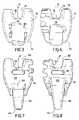
- FIG. 6shows a second embodiment of the implant of the invention, put into place between lumbar vertebra L5 and sacral vertebra S1.
- FIGS. 7 and 8show said first and second side faces of the body of the FIG. 6 spacer.
- FIG. 9is a section view of the body of the FIG. 6 spacer on its midplane M′.
- the fifth lumbar vertebra L5 and the top sacral vertebra S1are shown diagrammatically in FIG. 1 .
- vertebra L5presents a spinous process 10 .
- This process 10is situated in the sagittal plane of the spine.
- the vertebra S1does not possess a spinous process, and instead on its posterior face it presents a residual bulge 12 .
- the top portion of the vertebra S1forms a posterior arc 14 .
- the inside face of the posterior arcfaces the vertebral body 15 of the sacrum, it is concave, and it co-operates with the vertebral body to define an orifice through which there passes the spinal cord (not shown), which orifice is known as the vertebral foramen 16 .
- the implant of the inventionis suitable for being put into place between the spinous process 10 and the posterior arc 14 . It makes it possible to limit the movement of the vertebra L5 relative to the vertebra S1 and thus enables the intervertebral disk 17 situated between these two vertebrae to be relieved of the stresses that result from such movement.
- This implantconsists in a spacer 20 whose body 21 is shown in FIGS. 3 to 5 .
- the body of the spaceris made of a biocompatible material, e.g. a biopolymer.
- the body 21is molded out of polyetheretherketone, referred to below as PEEK.
- the polymeris of the type sold in particular under the trademark PEEK®.
- the body 21 of the spacerpresents a top end face 22 and a bottom end face 24 opposite from the face 22 . It also presents first and second opposite side faces 26 and 28 .
- the midplane M of the spacerintersects the faces 22 , 24 , 26 , and 28 , and it subdivides the body 21 into two almost symmetrical portions that differ from each other only by the presence in one of the portions of a cavity that is suitable for receiving fastener means.
- the plane Mcorresponds substantially to the sagittal plane of the spine.
- a groove 30 occupying the midplane M of the spacer 20is formed in the top end face 22 of the body 21 and is suitable for receiving the process 10 of the lumbar vertebra L5. This groove opens out into the side faces 26 and 28 .
- the section of the groove 30 in the plane perpendicular to the midplane M of the spaceris substantially U-shaped with a substantially plane base. This shape enables it to receive the bottom portion of the process 10 .
- the body 21 of the spacer 20presents an extension 32 at its bottom end, which extension has a first side 32 b extending the first side face 26 , and a second side 32 a opposite from the first side defining a setback relative to the second side face 28 of the body 21 of the spacer.
- the spacer 20also comprises a tab 34 connected to the body 21 of the spacer, and in the present example integrally molded therewith. The tab 34 extends facing the second side 32 a of the extension 32 and it is curved: it begins by going away from the side 32 a and from the face 26 , prior to coming closer to the side 32 a.
- the size of the tab 34 in the direction orthogonal to the midplane M of the spacer 20i.e. the width of the tab, is less than the width of the body 21 of the spacer.
- the width of the tab 34is substantially equal to 9 millimeters (mm)
- the width of the body 21and more particularly in the vicinity of the tab 34 in the zone that is to bear against the posterior arc 14 of the sacrum, is substantially equal to 18 mm, i.e. twice the width of the tab.
- the mean thickness of the tab 34is substantially equal to 2 mm. For a tab 34 made of PEEK, these dimensions are sufficient to enable the tab 34 to withstand the stresses to which it is subjected.
- This housing 36 formed in the bottom end face 24extends orthogonally relative to the groove 30 and is suitable for receiving the posterior arc 14 of the sacral vertebra S1.
- the section of the housing 36 in the midplane M of the spaceris generally U-shaped, and the midplane L of the housing 36 is not orthogonal to the midplane F defined by the bottom of the groove 30 .
- the midplane L of the housing 36is inclined relative to the midplane F at an angle I lying in the range 50° to 70°.
- This inclinationdepends firstly on the general inclination of the inside face 34 a of the tab 34 relative to the plane F, and secondly on the inclination of the second side 32 a of the extension 32 relative to said plane.
- a zone of the inside face 34 a of the tab 34is inclined relative to the midplane F at an angle A that is substantially equal to 70° as shown in FIG. 5
- a portion of the second side 32 a of the extension 32is inclined relative to the midplane F at an angle B that is substantially equal to 50°.
- the spaceralso presents first and second fastener means 42 and 44 serving to enable the body 21 of the spacer to be secured respectively to the process 10 of the lumbar vertebra L5, and to the sacral vertebra S1.
- fastener meansare similar to those described in document FR 01/03362, each comprising a strap 46 , 46 ′ and a fastener system secured to the body of the spacer.
- the fastener systemis formed by a plate suitable for being received inside a cavity of complementary shape formed in the body 21 of the spacer.
- the platepresents studs on two of its opposite side edges suitable for being engaged by force into housings provided for this purpose in the cavity of the body 21 so as to be held therein. This enables the plate to be secured to the body 21 of the spacer.
- Each platealso presents two slots through which the straps 46 , 46 ′ can be passed. These slots are inclined so as to allow the straps to move in one direction only, corresponding to tightening.
- the first end on the strap 46is passed through an oblong opening 48 situated along a first side of the groove 30 and passing through the body 21 of the spacer, and is then folded over and stitched to itself so as to form a loop. The first end of the strap 46 is thus secured to the body of the spacer 21 .
- the other end of the strap 46is passed into a fastener system situated along the side of the groove 30 that is opposite from said first side. When the spacer is put into place, the strap 46 is tightened around the process 10 .
- the second fastener means 44are shown in FIGS. 2 and 5 .
- a hole 38is formed in the body 21 of the spacer and opens out on one side into the bottom of the housing 36 in the vicinity of the tabs 34 , and on the other side into the bottom of the groove 30 .
- This holeis suitable for receiving a portion of the strap 46 ′.
- another hole 40is formed in the body 21 .
- This hole 40crosses the hole 38 orthogonally and is smaller in diameter than the hole 38 .
- the hole 40opens out on one side of the body of the spacer and is suitable for receiving a pin (not shown).
- the strap 46 ′is slid into the hole 38 and the pin is passed into a loop formed at the first end of said strap 46 ′.
- the first end of the strap 46 ′is secured to the body 21 of the spacer by means of the pin.
- the other end 46 ′is passed into the fastener system 44 situated on the first side face 26 of the body of the spacer.
- the strap 46 ′passes between the posterior arch 14 of the sacrum and the inside face 34 a of the tab 34 , then along a portion of the vertebra S1, prior to passing through an opening 60 made for this purpose in the sacrum after which it rises back towards the fastener system 44 .
- the outside face of the tabis smoother than the face of the strap. It is then advantageous since less trauma is involved for the spinal cord, to encourage contact between the tab 34 and the spinal cord and to limit contact between the strap 46 ′ and the spinal cord. That is why the tab 34 covers the strap 46 ′ when the spacer is in place.
- FIGS. 6 to 10A second embodiment of the implant of the invention is shown in FIGS. 6 to 10 .
- This implantlikewise consists in a spacer 120 . Since the shape of this spacer is close to that of the first embodiment, the numerical references specifying the portions of the spacer 120 that are similar to portions of the spacer 20 correspond to the numerical references used for the spacer 20 plus 100 .
- the top portion of the body 121 of the spacer 120is identical to that of the body 21 of the spacer 20 ; the body 121 presents a groove 130 for receiving the process of the vertebra L5, and the first fastener means 142 comprise a strap 146 held by a fastener system and serving to be tightened around the process 10 in such a manner as to hold it in the groove 130 .
- the bottom portion of the body 121differs from that of the body 21 .
- the tab 134is longer and wider than the tab 34 .
- the tab 134seeks to replace the fastener means 44 for fastening the spacer 20 to the sacrum, and therefore needs to be long enough to descend along the posterior arc 14 of the vertebra S1 and to ensure that the spacer 120 is held on said arc 14 .
- its length and its thicknessmainly in the vicinity of the body 121 of the spacer must be sufficient to prevent any breakage.
- the thickness of the tab 134is compensated by the absence of the strap, such that like the first embodiment, once the spacer 120 is in place, the tab 134 occupies as little space as possible inside the vertebral foramen, so as to limit contact with the spinal cord.
- the housing 136 situated in the bottom end face 124 of the spaceris defined by the tab 134 and the extension 132 .
- the section of this housing 136 on the midplane M of the spaceris generally U-shaped, and the mean plane L′ of said housing is inclined relative to the mean plane F′ defined by the bottom of the groove 130 by an angle I′ lying in the range 60° to 70°.
- the angles A and Brepresent respectively the inclination between a zone of the inside face 134 a of the tab 134 and the mean plane F′ defined by the bottom of the groove 130 , and the inclination between a portion of the second side 132 a of the extension 132 and the mean plane F′, and these angles are substantially equal respectively to 70° and 60°.
- the walls of the housing 136are closer to each other than in the first embodiment, and the angle that exists between the second side 132 a of the extension 132 and the inside face 134 a of the tab 134 is substantially equal to 10°, whereas it is nearer 20° in the first embodiment. Thereafter, the bottom of the housing 136 presents a concave shape that is more marked in order to receive more closely the top edge of the vertebra S1 which is convex.
- a notch 150is formed in the extension 132 facing the tab 134 so that when the spacer is being put into place, the residual bulge 12 situated on the posterior face of the vertebra S1 is received in the notch 150 , thus improving the stability of the spacer 120 on the sacrum.
- the bottom 150 a of the notch 150may be substantially parallel to the mean plane F′, or it may be inclined relative to said plane at an angle that is substantially equal to 20°, as shown in FIG. 9 .
- the spacer 120also presents a hole 152 parallel to the plane F′ defined by the bottom of the groove 130 and situated beneath said groove, passing through the body 121 of the spacer 120 .
- This holeopens out into the first and second side faces 126 and 128 of the body of the spacer 120 , and is provided to pass an instrument that is used for holding the spacer 120 while it is being put into place.
Landscapes
- Health & Medical Sciences (AREA)
- Orthopedic Medicine & Surgery (AREA)
- Neurology (AREA)
- Life Sciences & Earth Sciences (AREA)
- Surgery (AREA)
- Engineering & Computer Science (AREA)
- Biomedical Technology (AREA)
- General Health & Medical Sciences (AREA)
- Veterinary Medicine (AREA)
- Heart & Thoracic Surgery (AREA)
- Public Health (AREA)
- Animal Behavior & Ethology (AREA)
- Molecular Biology (AREA)
- Medical Informatics (AREA)
- Nuclear Medicine, Radiotherapy & Molecular Imaging (AREA)
- Neurosurgery (AREA)
- Cardiology (AREA)
- Oral & Maxillofacial Surgery (AREA)
- Transplantation (AREA)
- Vascular Medicine (AREA)
- Prostheses (AREA)
- Surgical Instruments (AREA)
Abstract
Description
Claims (14)
Applications Claiming Priority (3)
| Application Number | Priority Date | Filing Date | Title |
|---|---|---|---|
| FR0310063 | 2003-08-21 | ||
| FR0310063AFR2858929B1 (en) | 2003-08-21 | 2003-08-21 | "INTERVERTEBRAL IMPLANT FOR LOMBO-SACRED JOINT" |
| PCT/FR2004/002160WO2005020860A2 (en) | 2003-08-21 | 2004-08-19 | Intervertebral implant for the lumbosacral articulation |
Related Parent Applications (1)
| Application Number | Title | Priority Date | Filing Date |
|---|---|---|---|
| PCT/FR2004/002160A-371-Of-InternationalWO2005020860A2 (en) | 2003-08-21 | 2004-08-19 | Intervertebral implant for the lumbosacral articulation |
Related Child Applications (1)
| Application Number | Title | Priority Date | Filing Date |
|---|---|---|---|
| US12/749,115ContinuationUS8236056B2 (en) | 2003-08-21 | 2010-03-29 | Intervertebral implant for the lumbrosacral articulation |
Publications (2)
| Publication Number | Publication Date |
|---|---|
| US20070203491A1 US20070203491A1 (en) | 2007-08-30 |
| US7704281B2true US7704281B2 (en) | 2010-04-27 |
Family
ID=34112841
Family Applications (2)
| Application Number | Title | Priority Date | Filing Date |
|---|---|---|---|
| US10/568,307Expired - Fee RelatedUS7704281B2 (en) | 2003-08-21 | 2004-08-19 | Intervertebral implant for the lumbosacral articulation |
| US12/749,115Expired - Fee RelatedUS8236056B2 (en) | 2003-08-21 | 2010-03-29 | Intervertebral implant for the lumbrosacral articulation |
Family Applications After (1)
| Application Number | Title | Priority Date | Filing Date |
|---|---|---|---|
| US12/749,115Expired - Fee RelatedUS8236056B2 (en) | 2003-08-21 | 2010-03-29 | Intervertebral implant for the lumbrosacral articulation |
Country Status (10)
| Country | Link |
|---|---|
| US (2) | US7704281B2 (en) |
| EP (1) | EP1656075B1 (en) |
| JP (1) | JP4545749B2 (en) |
| KR (1) | KR101073367B1 (en) |
| AU (1) | AU2004268404B2 (en) |
| DE (1) | DE602004023519D1 (en) |
| ES (1) | ES2334356T3 (en) |
| FR (1) | FR2858929B1 (en) |
| WO (1) | WO2005020860A2 (en) |
| ZA (1) | ZA200601510B (en) |
Cited By (4)
| Publication number | Priority date | Publication date | Assignee | Title |
|---|---|---|---|---|
| US20130204303A1 (en)* | 2010-06-23 | 2013-08-08 | Cousin Biotech | Holding device having a longilineal element adapted for maintaining a predetermined intervertebral spacing |
| US8546456B2 (en) | 2008-07-25 | 2013-10-01 | Smith & Nephew, Inc. | Fracture fixation systems |
| US9358122B2 (en) | 2011-01-07 | 2016-06-07 | K2M, Inc. | Interbody spacer |
| US12011196B2 (en)* | 2011-09-28 | 2024-06-18 | Life Spine Inc. | Adjustable spine distraction implant |
Families Citing this family (76)
| Publication number | Priority date | Publication date | Assignee | Title |
|---|---|---|---|---|
| US6793678B2 (en) | 2002-06-27 | 2004-09-21 | Depuy Acromed, Inc. | Prosthetic intervertebral motion disc having dampening |
| FR2842724B1 (en) | 2002-07-23 | 2005-05-27 | Spine Next Sa | VERTEBRAL FASTENING SYSTEM |
| FR2858929B1 (en) | 2003-08-21 | 2005-09-30 | Spine Next Sa | "INTERVERTEBRAL IMPLANT FOR LOMBO-SACRED JOINT" |
| US8012209B2 (en)* | 2004-09-23 | 2011-09-06 | Kyphon Sarl | Interspinous process implant including a binder, binder aligner and method of implantation |
| US9055981B2 (en) | 2004-10-25 | 2015-06-16 | Lanx, Inc. | Spinal implants and methods |
| US8241330B2 (en) | 2007-01-11 | 2012-08-14 | Lanx, Inc. | Spinous process implants and associated methods |
| US8066742B2 (en)* | 2005-03-31 | 2011-11-29 | Warsaw Orthopedic, Inc. | Intervertebral prosthetic device for spinal stabilization and method of implanting same |
| FR2884135B1 (en)* | 2005-04-07 | 2007-06-22 | Abbott Spine Sa | INTERVERTEBRAL IMPLANT FOR LOMBO-SACRED JOINT |
| ES2556111T3 (en) | 2005-04-08 | 2016-01-13 | Paradigm Spine, Llc | Interspinous vertebral and lumbosacral stabilization devices |
| US7727279B2 (en)* | 2005-06-03 | 2010-06-01 | Zipnick Richard I | Minimally invasive apparatus to manipulate and revitalize spinal column disc |
| FR2889937B1 (en)* | 2005-08-26 | 2007-11-09 | Abbott Spine Sa | INTERVERTEBRAL IMPLANT FOR LOMBO-SACRED JOINT |
| FR2890850B1 (en) | 2005-09-20 | 2009-04-17 | Abbott Spine Sa | VERTEBRAL FASTENING SYSTEM |
| FR2890851B1 (en) | 2005-09-21 | 2008-06-20 | Abbott Spine Sa | ANCILLARY TO TENSION A FLEXIBLE LINK. |
| EP1942817B1 (en) | 2005-09-27 | 2014-05-07 | Paradigm Spine, LLC | Interspinous vertebral stabilization devices |
| US8357181B2 (en) | 2005-10-27 | 2013-01-22 | Warsaw Orthopedic, Inc. | Intervertebral prosthetic device for spinal stabilization and method of implanting same |
| US7862591B2 (en) | 2005-11-10 | 2011-01-04 | Warsaw Orthopedic, Inc. | Intervertebral prosthetic device for spinal stabilization and method of implanting same |
| US8083795B2 (en) | 2006-01-18 | 2011-12-27 | Warsaw Orthopedic, Inc. | Intervertebral prosthetic device for spinal stabilization and method of manufacturing same |
| WO2007087535A2 (en)* | 2006-01-23 | 2007-08-02 | Pioneer Surgical Technology, Inc. | Interlaminar stabilizing system |
| US9011441B2 (en) | 2006-02-17 | 2015-04-21 | Paradigm Spine, L.L.C. | Method and system for performing interspinous space preparation for receiving an implant |
| DE102007018860B4 (en) | 2006-04-28 | 2023-01-05 | Paradigm Spine L.L.C. | Instrument system for use with an interspinous implant |
| FR2907329B1 (en)* | 2006-10-20 | 2009-02-27 | Jean Taylor | INTEREPINEAL VERTEBRAL PROSTHESIS |
| EP2047813A1 (en) | 2007-10-11 | 2009-04-15 | Abbott Spine | Bone fixing system and method of use |
| AR064013A1 (en) | 2006-11-30 | 2009-03-04 | Paradigm Spine Llc | VERTEBRAL, INTERLAMINAR, INTERESPINOUS STABILIZATION SYSTEM |
| WO2008070863A2 (en) | 2006-12-07 | 2008-06-12 | Interventional Spine, Inc. | Intervertebral implant |
| US11395626B2 (en) | 2006-12-07 | 2022-07-26 | DePuy Synthes Products, Inc. | Sensor for intervertebral fusion indicia |
| US7850732B2 (en)* | 2006-12-11 | 2010-12-14 | Warsaw Orthopedic, Inc. | Sacral prosthesis and surgical method |
| US9247968B2 (en) | 2007-01-11 | 2016-02-02 | Lanx, Inc. | Spinous process implants and associated methods |
| US9265532B2 (en) | 2007-01-11 | 2016-02-23 | Lanx, Inc. | Interspinous implants and methods |
| US8900307B2 (en) | 2007-06-26 | 2014-12-02 | DePuy Synthes Products, LLC | Highly lordosed fusion cage |
| FR2921248A1 (en) | 2007-09-25 | 2009-03-27 | Abbott Spine Sa | DEVICE FOR TIGHTENING TWO PORTIONS OF A BRAID AND INTERVERTEBRAL IMPLANT COMPRISING A BILGE, A BRAID AND A SUCH TIGHTENING DEVICE |
| US8128635B2 (en) | 2007-10-23 | 2012-03-06 | Zimmer Spine S.A.S. | Bone fixation tensioning tool and method |
| ATE536824T1 (en) | 2007-10-23 | 2011-12-15 | Zimmer Spine | FASTENING DEVICES AND STABILIZATION SYSTEMS WITH THESE FASTENING DEVICES |
| EP2237748B1 (en) | 2008-01-17 | 2012-09-05 | Synthes GmbH | An expandable intervertebral implant |
| KR101435521B1 (en)* | 2008-01-23 | 2014-08-29 | 삼성전자 주식회사 | Biochip |
| US8936641B2 (en) | 2008-04-05 | 2015-01-20 | DePuy Synthes Products, LLC | Expandable intervertebral implant |
| ATE515239T1 (en) | 2008-04-24 | 2011-07-15 | Zimmer Spine | SYSTEM FOR STABILIZING AT LEAST ONE SECTION OF THE SPINE |
| EP2303163B1 (en) | 2008-05-20 | 2011-11-23 | Zimmer Spine | System for stabilizing at least three vertebrae |
| ES2361099B1 (en)* | 2008-05-26 | 2012-05-08 | Rudolf Morgenstern Lopez | "INTERVERTEBRAL PROSTHESIS" |
| EP2138122A1 (en) | 2008-06-25 | 2009-12-30 | Abbott Spine | Stabilization system between a sacrum and a lumbar vertebra |
| US9526620B2 (en) | 2009-03-30 | 2016-12-27 | DePuy Synthes Products, Inc. | Zero profile spinal fusion cage |
| US8157842B2 (en) | 2009-06-12 | 2012-04-17 | Kyphon Sarl | Interspinous implant and methods of use |
| US9393129B2 (en) | 2009-12-10 | 2016-07-19 | DePuy Synthes Products, Inc. | Bellows-like expandable interbody fusion cage |
| GB0922614D0 (en)* | 2009-12-23 | 2010-02-10 | Butterfield Forbes | Device |
| FR2960767A1 (en)* | 2010-06-04 | 2011-12-09 | Hpi | Device for fixing prosthesis i.e. interspinous implant, between lumbar vertebra and sacral vertebra during surgery of spinal column, has artificial apophysis comprising projection cooperating with interspinous implant |
| US9907560B2 (en) | 2010-06-24 | 2018-03-06 | DePuy Synthes Products, Inc. | Flexible vertebral body shavers |
| US8979860B2 (en) | 2010-06-24 | 2015-03-17 | DePuy Synthes Products. LLC | Enhanced cage insertion device |
| US8623091B2 (en) | 2010-06-29 | 2014-01-07 | DePuy Synthes Products, LLC | Distractible intervertebral implant |
| US9402732B2 (en) | 2010-10-11 | 2016-08-02 | DePuy Synthes Products, Inc. | Expandable interspinous process spacer implant |
| US8496689B2 (en) | 2011-02-23 | 2013-07-30 | Farzad Massoudi | Spinal implant device with fusion cage and fixation plates and method of implanting |
| US8425560B2 (en) | 2011-03-09 | 2013-04-23 | Farzad Massoudi | Spinal implant device with fixation plates and lag screws and method of implanting |
| WO2013040456A1 (en) | 2011-09-14 | 2013-03-21 | Band-Lok, Llc | Tether clamp and implantation system |
| US11812923B2 (en) | 2011-10-07 | 2023-11-14 | Alan Villavicencio | Spinal fixation device |
| KR101121667B1 (en)* | 2012-01-17 | 2012-03-09 | 김창국 | Interspinous spinal spacer |
| EP2877127B1 (en) | 2012-07-26 | 2019-08-21 | Synthes GmbH | Expandable implant |
| US20140067069A1 (en) | 2012-08-30 | 2014-03-06 | Interventional Spine, Inc. | Artificial disc |
| US9717601B2 (en) | 2013-02-28 | 2017-08-01 | DePuy Synthes Products, Inc. | Expandable intervertebral implant, system, kit and method |
| US9522070B2 (en) | 2013-03-07 | 2016-12-20 | Interventional Spine, Inc. | Intervertebral implant |
| US9675386B2 (en) | 2013-03-11 | 2017-06-13 | K2M, Inc. | Flexible fastening system |
| US10064656B2 (en) | 2015-02-12 | 2018-09-04 | K2M, Inc. | Spinal fixation construct and methods of use |
| US11426290B2 (en) | 2015-03-06 | 2022-08-30 | DePuy Synthes Products, Inc. | Expandable intervertebral implant, system, kit and method |
| US9757167B2 (en) | 2015-03-11 | 2017-09-12 | K2M, Inc. | Inserter and method for securing an implant to a spinal process with a flexible fastening system |
| US9913727B2 (en) | 2015-07-02 | 2018-03-13 | Medos International Sarl | Expandable implant |
| US11510788B2 (en) | 2016-06-28 | 2022-11-29 | Eit Emerging Implant Technologies Gmbh | Expandable, angularly adjustable intervertebral cages |
| EP3474784A2 (en) | 2016-06-28 | 2019-05-01 | Eit Emerging Implant Technologies GmbH | Expandable and angularly adjustable intervertebral cages with articulating joint |
| EP3490474A4 (en) | 2016-07-26 | 2019-08-28 | Band-lok, LLC | ORTHOPEDIC IMPLANTS. |
| EP3525699B1 (en) | 2016-10-11 | 2023-07-26 | K2M, Inc. | Spinal implant |
| US10537436B2 (en) | 2016-11-01 | 2020-01-21 | DePuy Synthes Products, Inc. | Curved expandable cage |
| US10888433B2 (en) | 2016-12-14 | 2021-01-12 | DePuy Synthes Products, Inc. | Intervertebral implant inserter and related methods |
| US10398563B2 (en) | 2017-05-08 | 2019-09-03 | Medos International Sarl | Expandable cage |
| US11344424B2 (en) | 2017-06-14 | 2022-05-31 | Medos International Sarl | Expandable intervertebral implant and related methods |
| US10940016B2 (en) | 2017-07-05 | 2021-03-09 | Medos International Sarl | Expandable intervertebral fusion cage |
| US11446156B2 (en) | 2018-10-25 | 2022-09-20 | Medos International Sarl | Expandable intervertebral implant, inserter instrument, and related methods |
| US11426286B2 (en) | 2020-03-06 | 2022-08-30 | Eit Emerging Implant Technologies Gmbh | Expandable intervertebral implant |
| US11850160B2 (en) | 2021-03-26 | 2023-12-26 | Medos International Sarl | Expandable lordotic intervertebral fusion cage |
| US11752009B2 (en) | 2021-04-06 | 2023-09-12 | Medos International Sarl | Expandable intervertebral fusion cage |
| US12090064B2 (en) | 2022-03-01 | 2024-09-17 | Medos International Sarl | Stabilization members for expandable intervertebral implants, and related systems and methods |
Citations (10)
| Publication number | Priority date | Publication date | Assignee | Title |
|---|---|---|---|---|
| FR2714591A1 (en) | 1994-01-06 | 1995-07-07 | Euros Sa | Lumbar-sacral prosthetic implant for use in treatment of scoliosis or degenerative diseases |
| US5810815A (en) | 1996-09-20 | 1998-09-22 | Morales; Jose A. | Surgical apparatus for use in the treatment of spinal deformities |
| US5836948A (en)* | 1997-01-02 | 1998-11-17 | Saint Francis Medical Technologies, Llc | Spine distraction implant and method |
| FR2775183A1 (en) | 1998-02-20 | 1999-08-27 | Jean Taylor | INTER-SPINOUS PROSTHESIS |
| FR2799640A1 (en) | 1999-10-15 | 2001-04-20 | Spine Next Sa | Intervertebral implant has wedge with opposed recesses to receive spinous processes and retained by strap |
| EP1138268A1 (en) | 2000-03-21 | 2001-10-04 | Cousin Biotech (S.A.S.) | Device for the fixation of an interspinous wedge on the sacrum |
| WO2002071960A1 (en) | 2001-03-13 | 2002-09-19 | Spine Next | Self locking fixable intervertebral implant |
| US20030028250A1 (en)* | 1999-10-22 | 2003-02-06 | Archus Orthopedics, Inc. | Prostheses, systems and methods for replacement of natural facet joints with artifical facet joint surfaces |
| US20030040746A1 (en)* | 2001-07-20 | 2003-02-27 | Mitchell Margaret E. | Spinal stabilization system and method |
| US20070203491A1 (en) | 2003-08-21 | 2007-08-30 | Abbott Spine | Intervertebral implant for the lumbosacral articulation |
Family Cites Families (1)
| Publication number | Priority date | Publication date | Assignee | Title |
|---|---|---|---|---|
| US6792329B2 (en)* | 2001-08-22 | 2004-09-14 | Milliken & Company | Construction of colored images on absorbent substrates using a computer-aided design system |
- 2003
- 2003-08-21FRFR0310063Apatent/FR2858929B1/ennot_activeExpired - Fee Related
- 2004
- 2004-08-19USUS10/568,307patent/US7704281B2/ennot_activeExpired - Fee Related
- 2004-08-19AUAU2004268404Apatent/AU2004268404B2/ennot_activeCeased
- 2004-08-19ZAZA200601510Apatent/ZA200601510B/enunknown
- 2004-08-19ESES04786326Tpatent/ES2334356T3/ennot_activeExpired - Lifetime
- 2004-08-19KRKR1020067003375Apatent/KR101073367B1/ennot_activeExpired - Fee Related
- 2004-08-19DEDE602004023519Tpatent/DE602004023519D1/ennot_activeExpired - Lifetime
- 2004-08-19JPJP2006523655Apatent/JP4545749B2/ennot_activeExpired - Fee Related
- 2004-08-19WOPCT/FR2004/002160patent/WO2005020860A2/enactiveApplication Filing
- 2004-08-19EPEP04786326Apatent/EP1656075B1/ennot_activeExpired - Lifetime
- 2010
- 2010-03-29USUS12/749,115patent/US8236056B2/ennot_activeExpired - Fee Related
Patent Citations (12)
| Publication number | Priority date | Publication date | Assignee | Title |
|---|---|---|---|---|
| FR2714591A1 (en) | 1994-01-06 | 1995-07-07 | Euros Sa | Lumbar-sacral prosthetic implant for use in treatment of scoliosis or degenerative diseases |
| US5810815A (en) | 1996-09-20 | 1998-09-22 | Morales; Jose A. | Surgical apparatus for use in the treatment of spinal deformities |
| US5836948A (en)* | 1997-01-02 | 1998-11-17 | Saint Francis Medical Technologies, Llc | Spine distraction implant and method |
| FR2775183A1 (en) | 1998-02-20 | 1999-08-27 | Jean Taylor | INTER-SPINOUS PROSTHESIS |
| US6626944B1 (en)* | 1998-02-20 | 2003-09-30 | Jean Taylor | Interspinous prosthesis |
| FR2799640A1 (en) | 1999-10-15 | 2001-04-20 | Spine Next Sa | Intervertebral implant has wedge with opposed recesses to receive spinous processes and retained by strap |
| US20030028250A1 (en)* | 1999-10-22 | 2003-02-06 | Archus Orthopedics, Inc. | Prostheses, systems and methods for replacement of natural facet joints with artifical facet joint surfaces |
| EP1138268A1 (en) | 2000-03-21 | 2001-10-04 | Cousin Biotech (S.A.S.) | Device for the fixation of an interspinous wedge on the sacrum |
| WO2002071960A1 (en) | 2001-03-13 | 2002-09-19 | Spine Next | Self locking fixable intervertebral implant |
| FR2822051A1 (en) | 2001-03-13 | 2002-09-20 | Spine Next Sa | INTERVERTEBRAL IMPLANT WITH SELF-LOCKING ATTACHMENT |
| US20030040746A1 (en)* | 2001-07-20 | 2003-02-27 | Mitchell Margaret E. | Spinal stabilization system and method |
| US20070203491A1 (en) | 2003-08-21 | 2007-08-30 | Abbott Spine | Intervertebral implant for the lumbosacral articulation |
Cited By (6)
| Publication number | Priority date | Publication date | Assignee | Title |
|---|---|---|---|---|
| US8546456B2 (en) | 2008-07-25 | 2013-10-01 | Smith & Nephew, Inc. | Fracture fixation systems |
| US9730740B2 (en) | 2008-07-25 | 2017-08-15 | Smith & Nephew, Inc. | Fracture fixation systems |
| US20130204303A1 (en)* | 2010-06-23 | 2013-08-08 | Cousin Biotech | Holding device having a longilineal element adapted for maintaining a predetermined intervertebral spacing |
| US9179942B2 (en)* | 2010-06-23 | 2015-11-10 | Cousin Biotech | Holding device having a longilineal element adapted for maintaining a predetermined intervertebral spacing |
| US9358122B2 (en) | 2011-01-07 | 2016-06-07 | K2M, Inc. | Interbody spacer |
| US12011196B2 (en)* | 2011-09-28 | 2024-06-18 | Life Spine Inc. | Adjustable spine distraction implant |
Also Published As
| Publication number | Publication date |
|---|---|
| DE602004023519D1 (en) | 2009-11-19 |
| FR2858929A1 (en) | 2005-02-25 |
| JP4545749B2 (en) | 2010-09-15 |
| JP2007502636A (en) | 2007-02-15 |
| WO2005020860A3 (en) | 2005-05-19 |
| ZA200601510B (en) | 2007-05-30 |
| KR20060080646A (en) | 2006-07-10 |
| EP1656075B1 (en) | 2009-10-07 |
| US20100185243A1 (en) | 2010-07-22 |
| EP1656075A2 (en) | 2006-05-17 |
| US8236056B2 (en) | 2012-08-07 |
| WO2005020860A2 (en) | 2005-03-10 |
| KR101073367B1 (en) | 2011-10-13 |
| AU2004268404A1 (en) | 2005-03-10 |
| FR2858929B1 (en) | 2005-09-30 |
| ES2334356T3 (en) | 2010-03-09 |
| AU2004268404B2 (en) | 2010-06-03 |
| US20070203491A1 (en) | 2007-08-30 |
Similar Documents
| Publication | Publication Date | Title |
|---|---|---|
| US7704281B2 (en) | Intervertebral implant for the lumbosacral articulation | |
| JP4887360B2 (en) | Cervical anterior plate | |
| US7371238B2 (en) | Method and device for treating scoliosis | |
| AU2005251756B2 (en) | Variable laminoplasty implant | |
| EP1372537B1 (en) | Intervertebral connection system | |
| US20060265068A1 (en) | Intervertebral implant | |
| US20090216276A1 (en) | Intervertebral implant for lumbosacral joint | |
| US20120221052A1 (en) | Distance-keeping inter-process implant | |
| KR20100080908A (en) | Interspinous spacer | |
| US20130150892A1 (en) | Anchor for attachment to a bony structure | |
| US10188434B2 (en) | Hybrid multifunctional posterior interspinous fusion device | |
| US20230165603A1 (en) | Bone anchor with deployable purchase element | |
| US9833266B2 (en) | Implantable vertebral arthrodesis device for fusing two overlying and underlying vertebrae | |
| EP2073733B1 (en) | Interspinous spinal prosthesis | |
| US20150289986A1 (en) | Flanged endplate for an intervertebral disc prosthesis and intervertebral disc prosthesis incorporating same | |
| KR100495227B1 (en) | Instrument maintaining a space of the vertebra | |
| JP2000175944A (en) | Artificial vertebral arch |
Legal Events
| Date | Code | Title | Description |
|---|---|---|---|
| AS | Assignment | Owner name:ABBOTT SPINE,FRANCE Free format text:ASSIGNMENT OF ASSIGNORS INTEREST;ASSIGNORS:PASQUET, DENIS;LE COUEDIC, REGIS;RENAUD, CHRISTIAN;SIGNING DATES FROM 20060413 TO 20060626;REEL/FRAME:018236/0584 Owner name:ABBOTT SPINE, FRANCE Free format text:ASSIGNMENT OF ASSIGNORS INTEREST;ASSIGNORS:PASQUET, DENIS;LE COUEDIC, REGIS;RENAUD, CHRISTIAN;REEL/FRAME:018236/0584;SIGNING DATES FROM 20060413 TO 20060626 | |
| AS | Assignment | Owner name:ZIMMER SPINE AUSTIN, INC., TEXAS Free format text:CHANGE OF NAME;ASSIGNOR:ABBOTT SPINE INC.;REEL/FRAME:022390/0379 Effective date:20081215 Owner name:ZIMMER SPINE AUSTIN, INC.,TEXAS Free format text:CHANGE OF NAME;ASSIGNOR:ABBOTT SPINE INC.;REEL/FRAME:022390/0379 Effective date:20081215 | |
| AS | Assignment | Owner name:ZIMMER SPINE, FRANCE Free format text:CHANGE OF NAME;ASSIGNOR:ABBOTT SPINE;REEL/FRAME:023452/0404 Effective date:20090220 Owner name:ZIMMER SPINE,FRANCE Free format text:CHANGE OF NAME;ASSIGNOR:ABBOTT SPINE;REEL/FRAME:023452/0404 Effective date:20090220 | |
| AS | Assignment | Owner name:ZIMMER SPINE,FRANCE Free format text:CHANGE OF NAME;ASSIGNOR:ABBOTT SPINE;REEL/FRAME:024087/0208 Effective date:20090220 | |
| STCF | Information on status: patent grant | Free format text:PATENTED CASE | |
| CC | Certificate of correction | ||
| FPAY | Fee payment | Year of fee payment:4 | |
| MAFP | Maintenance fee payment | Free format text:PAYMENT OF MAINTENANCE FEE, 8TH YEAR, LARGE ENTITY (ORIGINAL EVENT CODE: M1552) Year of fee payment:8 | |
| FEPP | Fee payment procedure | Free format text:MAINTENANCE FEE REMINDER MAILED (ORIGINAL EVENT CODE: REM.); ENTITY STATUS OF PATENT OWNER: LARGE ENTITY | |
| LAPS | Lapse for failure to pay maintenance fees | Free format text:PATENT EXPIRED FOR FAILURE TO PAY MAINTENANCE FEES (ORIGINAL EVENT CODE: EXP.); ENTITY STATUS OF PATENT OWNER: LARGE ENTITY | |
| STCH | Information on status: patent discontinuation | Free format text:PATENT EXPIRED DUE TO NONPAYMENT OF MAINTENANCE FEES UNDER 37 CFR 1.362 | |
| FP | Lapsed due to failure to pay maintenance fee | Effective date:20220427 |