US7704257B2 - Compression instrument - Google Patents
Compression instrumentDownload PDFInfo
- Publication number
- US7704257B2 US7704257B2US11/285,808US28580805AUS7704257B2US 7704257 B2US7704257 B2US 7704257B2US 28580805 AUS28580805 AUS 28580805AUS 7704257 B2US7704257 B2US 7704257B2
- Authority
- US
- United States
- Prior art keywords
- handle
- sledge
- bone
- sleeve
- instrument
- Prior art date
- Legal status (The legal status is an assumption and is not a legal conclusion. Google has not performed a legal analysis and makes no representation as to the accuracy of the status listed.)
- Expired - Fee Related, expires
Links
Images


Classifications
- A—HUMAN NECESSITIES
- A61—MEDICAL OR VETERINARY SCIENCE; HYGIENE
- A61B—DIAGNOSIS; SURGERY; IDENTIFICATION
- A61B17/00—Surgical instruments, devices or methods
- A61B17/56—Surgical instruments or methods for treatment of bones or joints; Devices specially adapted therefor
- A61B17/58—Surgical instruments or methods for treatment of bones or joints; Devices specially adapted therefor for osteosynthesis, e.g. bone plates, screws or setting implements
- A61B17/68—Internal fixation devices, including fasteners and spinal fixators, even if a part thereof projects from the skin
- A61B17/80—Cortical plates, i.e. bone plates; Instruments for holding or positioning cortical plates, or for compressing bones attached to cortical plates
- A61B17/8004—Cortical plates, i.e. bone plates; Instruments for holding or positioning cortical plates, or for compressing bones attached to cortical plates with means for distracting or compressing the bone or bones
- A61B17/8019—Cortical plates, i.e. bone plates; Instruments for holding or positioning cortical plates, or for compressing bones attached to cortical plates with means for distracting or compressing the bone or bones where the means are a separate tool rather than being part of the plate
- A—HUMAN NECESSITIES
- A61—MEDICAL OR VETERINARY SCIENCE; HYGIENE
- A61B—DIAGNOSIS; SURGERY; IDENTIFICATION
- A61B17/00—Surgical instruments, devices or methods
- A61B17/16—Instruments for performing osteoclasis; Drills or chisels for bones; Trepans
- A61B17/17—Guides or aligning means for drills, mills, pins or wires
- A61B17/1728—Guides or aligning means for drills, mills, pins or wires for holes for bone plates or plate screws
Definitions
- the present inventionrelates to the field of bone fracture repair, and more particularly, to a compression instrument for use in conjunction with a bone plate.
- bone plates and other fixation meanshave been widely utilized by doctors and surgeons for repairing fractures formed in bones. Such fractures typically result in otherwise unitary bone structures being split into two or more fragments, with many of these bone fractures resulting in two separate fragments. Essentially, it has been the general practice to reset the different bone fragments to their original position, place a bone plate across the fragments, and affix the plate to each of the fragments through the use of screws or other fixation means. This allows the different fragments to reattach to one another through recalcification so as to permit the fractured pieces to be reformed into the original bone structure. During this process, the affixed bone plate preferably ensures that the fragments remain in their original position, and provides a certain level of support to the bone structure.
- a first aspect of the present inventionis a method of moving a first bone fragment with respect to a second bone fragment.
- the method according to this aspectmay include the steps of placing a bone plate adjacent and across the first and second bone fragments, affixing a first side of the bone plate to the first bone fragment, positioning an instrument in a hole formed in the bone plate and arranging an elongate element through a cannulated opening in said instrument and into the second bone fragment, causing a first portion of the instrument to move in a first direction to move a second portion of the instrument in a second direction which is different than said first direction, the movement of the first portion causing the second bone fragment to move with respect to the first bone fragment, and affixing a second side of the bone plate to the second bone fragment.
- the methodmay include utilizing fixation means selected from the group consisting of screws, nails, bolts and staples.
- the elongate elementmay be selected from the group consisting of K-wires, drills, pins, screws, nails and bolts.
- the methodmay be performed to move the first and second bone fragments towards or away from one another.
- the instrumentmay include a handle, a sledge, a sleeve and a knob. In these embodiments, rotation of the knob may move the sledge and sleeve in a direction perpendicular to a longitudinal axis of the handle.
- the instrumentincludes a handle having a longitudinal axis, a sledge inserted into a portion of the handle and a knob connected to the handle, the sledge being movable with respect to the handle. Movement of the knob may cause movement of the sledge with respect to the handle. This movement may be in a direction perpendicular to the longitudinal axis of the handle.
- the instrumentmay also include a sleeve inserted through the handle and the sledge.
- the handlemay include a cut out section for receiving the sledge and first and third parts of a channel for receiving the sleeve.
- the sledgemay include a second part of the channel for receiving the sleeve.
- the sleevemay be sized to move within the first and third parts of the channel.
- the sleevemay also be cannulated for receiving an elongate element therethrough.
- the knobmay be threadably connected to the handle and the instrument may include a nut threadably connected to the knob.
- the sledgemay also include at least one groove for cooperating with at least one protrusion of the handle. Rotation of the knob may cause translation of the sledge in a direction perpendicular to the longitudinal axis of the handle.
- the handlemay further include a tip for insertion into a hole formed through a bone plate.
- the kitincludes at least one bone plate, at least one elongate element and at least one instrument each having a first portion adapted to cooperate with the bone plate, a second portion adapted to move with respect to the first portion, and a third portion adapted to cause movement of the second portion with respect to the first portion.
- the elongate elementmay be capable of being arranged with the instrument and movement of the second portion of the instrument may be capable of causing the elongate element to move with respect to the first portion of the instrument.
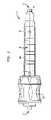
- FIG. 1is a perspective view of a compression instrument in accordance with an embodiment of the present invention.
- FIG. 2is a top view of the compression instrument shown in FIG. 1 .
- FIG. 3is an exploded perspective view of the compression instrument shown in FIG. 1 .
- FIG. 4is a perspective view of a handle portion of the compression instrument shown in FIG. 1 .
- FIG. 5is a perspective view of a sledge portion of the compression instrument shown in FIG. 1 .
- FIG. 6is a perspective view of a sleeve portion of the compression instrument shown in FIG. 1 .
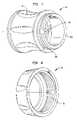
- FIG. 7is a perspective view of a knob portion of the compression instrument shown in FIG. 1 .
- FIG. 8is a perspective view of a nut portion of the compression instrument shown in FIG. 1 .
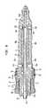
- FIG. 9is a cross sectional side view of the compression instrument shown in FIG. 1 .
- FIGS. 10 a and 10 bare illustrations depicting use of the compression instrument shown in FIG. 1 .
- FIG. 11is an illustration depicting use of a compression instrument according to a second embodiment of the present invention.
- FIG. 1a compression instrument designated generally by reference numeral 10 .
- Compression instrument 10is preferably usable in conjunction with many different types of bone plates or other such devices, including but not limited to, the bone plate assembly disclosed in commonly owned U.S. patent application Ser. No. 10/999,132 filed on Nov. 29, 2004, the disclosure of which is hereby incorporated by reference herein.
- compression instrument 10 of the present inventionmay be easily modified in order to be utilized in conjunction with many different bone plates. This will be discussed further below. As best shown in FIGS.
- compression instrument 10may be an elongate structure having a proximal end 12 and a distal end 14 .
- Compression instrument 10is preferably sized and configured so as to allow a surgeon or other medical professional to grip and manipulate the instrument.
- compression instrument 10may also be sized so as to allow its insertion into an incision or other opening in the body, as will be more completely discussed below in the discussion relating to the method of utilizing the present invention.
- compression instrument 10may include a handle 16 , a sledge portion 18 , a K-wire sleeve 20 , a knob 22 and a nut 24 . These elements are each more particularly shown in FIGS. 4-8 , respectively. Preferably, each of the elements may be interconnected with each other so as to form a single contained unit. However, it is to be understood that compression instrument 10 may include fewer or more elements in its fully constructed form. For example, as shown in FIG. 3 , compression instrument 10 may further include a spring assembly 26 , which prevents sleeve 20 from falling out of a fully constructed instrument 10 . This will be more fully discussed below, as will each of the individual elements of compression instrument 10 .
- handle 16is more particularly depicted apart from the other elements of compression instrument 10 .
- handle 16may provide the majority of the structure included in instrument 10 , as well as its elongate nature.
- handle 16essentially extends between the aforementioned proximal and distal ends 12 and 14 , and as such, these ends are shown in FIG. 4 .
- Handle 16is preferably a tubular structure and may include three distinct sections, a distal section 30 , a gripping section 32 , and a tip section 34 .
- Distal section 30preferably has a threaded portion 36 for cooperating with knob 22 (this cooperation is best shown in FIG.
- a first part 28 a of a channel 28extends through distal section 30 .
- Gripping section 32is essentially a larger and/or raised section, with respect to sections 30 and 34 .
- gripping section 32may include opposed undulating surfaces 38 a and 38 b for improved gripping, and a cut out section 40 with protrusions 42 a, 42 b, 42 c and 42 d extending therein, for receiving and cooperating with sledge 18 .
- tip section 34is preferably circular in cross section, and may include a proximal-most tip 44 for engaging a like sized hole on a plate.
- the tip section 34includes a third part 28 c of channel 28 extending therethrough.
- sledge portion 18is preferably a unitary body having a first body portion 46 and a second body portion 48 , wherein each of the first and second body portions may have a substantially rectangular cross-sectional shape. Additionally, first body 46 is preferably wider than second body 48 , so that a portion of it extends beyond the remainder of sledge 18 along at least one direction. This width or size difference allows for cooperation with the other elements of instrument 10 during operation, as will be more fully discussed below.
- Second body 48preferably includes four grooves or slots 50 a, 50 b, 50 c and 50 d, which may be angled and/or include angled sections that are adapted to mate with protrusions 42 a, 42 b, 42 c and 42 d of handle 16 .
- sledge portion 18may include a second part 28 b of channel 28 extending therethrough.
- channel 28includes first part or section 28 a formed through distal section 30 of handle 16 , second part of section 28 b formed through sledge 18 , and third part or section 28 c formed through tip section 34 of handle 16 .
- a continuous channel 28may be formed in the fully assembled instrument 10 .
- FIG. 6depicts sleeve 20 , which is preferably adapted to fit over a K-wire or other elongate element which, in turn, may be adapted to be embedded in a bony body or the like.
- Sleeve 20is also preferably a unitary substantially tubular body sized and configured to fit within channel 28 formed in handle 16 and sledge portion 18 .
- sleeve 20may be sized and configured to fit within channel 28 , such that there may be a predetermined amount of clearance between the sleeve and the first and third parts 28 a and 28 c, but substantially no clearance between the sleeve and the second part 28 b.
- sleeve 20may be sized so as to have a diameter which is somewhat smaller than that of the first and third parts of channel 28 , and substantially the same as that of part 28 b.
- sleeve 20may include a shoulder portion 52 for insertion into the above discussed rectangular opening 37 of handle 16 .
- the rectangular opening 37may be sized so as to be larger than shoulder portion 52 , so as to provide the same or a different amount of clearance there between as compared to the clearance between sleeve 20 and parts 28 a and 28 c of channel 28 .
- the aforementioned spring assembly 26may be inserted into an opening 54 on shoulder portion 52 so as to prevent sleeve 20 from falling out of a fully constructed instrument 10 . In operation, spring assembly 26 may exert a force upon a portion of rectangular opening 37 to prevent the inadvertent movement or removal of sleeve 20 therefrom.
- the remainder of sleeve 20may include like sized tubular portions 56 and 58 , and a smaller diameter, stepped down tubular portion 60 .
- a sleeve channel 62(best shown in the cross sectional view of FIG. 9 ) runs through sleeve 20 . As shown in FIG. 9 , this channel may include differently sized sections 62 a and 62 b, or alternatively, may be one size. In a preferred embodiment, sleeve channel 62 is sized to fit a K-wire or the like therein. However, channel 62 may also be sized so as to allow insertion of a rod, nail, screw or the like therein.
- FIGS. 7 and 8more specifically depict knob 22 and nut 24 , respectively.
- Knob 22may be a tubular structure having a gripping surface 64 for allowing easy gripping and rotating by a surgeon or operator.
- Knob 22is preferably sized and configured to fit over distal section 30 of handle 16 . More specifically, knob 22 may include an internal threaded surface 66 for engaging threaded surface 36 of handle 16 . Additionally, knob 22 may also include an external threaded surface 68 for engaging nut 24 .
- Nut 24may be a tubular structure with an internal threaded surface 70 for engaging the aforementioned external threaded surface 68 of knob 22 . Essentially, nut 24 allows the easy assembly and disassembly of instrument 10 .
- instrument 10may vary in their particular construction, including in their size and configuration.
- sleeve 20may be sized differently in order to slide over different elongate elements inserted into the bone.
- various elements of instrument 10may be constructed of many different types of materials.
- the components of instrument 10may be constructed of bio-compatible materials suitable for insertion into the body of a patient, such as stainless steel or polymer materials. Titanium, aluminum and fiber-reinforced plastics may also be utilized.
- certain elementsmay be constructed of one type of certain material, while other elements may be constructed from a second and different type of material.
- handle 16may be constructed of a polymeric material for easy manufacturing, while sleeve 20 may be constructed of stainless steel to insure acceptable use with stainless steel elongate elements inserted in the bone.
- sledge 18may be inserted into cut out section 40 of handle 16 , such that protrusions 42 a, 42 b, 42 c and 42 d extend into grooves 50 a, 50 b, 50 c and 50 d.
- sleeve 20may be slid into and through all three parts 28 a, 28 b and 28 c of channel 28 , and shoulder portion 52 of sleeve 20 may be inserted into rectangular opening 37 of handle 16 .
- spring assembly 26may also be engaged with rectangular opening 37 , so as to prevent the inadvertent removal or movement of sleeve 20 from handle 16 . As such, sleeve 20 is held in place.
- knob 22may be slid over distal section 30 of handle 16 , and its internal threaded surface 66 can be threadably engaged with external threaded portion 36 of distal section 30 .
- an end face 68 a of surface 68 of knob 22may abut rectangular body 46 of sledge 18 .
- any translational motion of knob 22in a direction depicted by arrow B ( FIGS. 9-10 b ), may be imparted to sledge 18 .
- knob 24is slid over tip section 34 and gripping section 32 of handle 16 , and threadably engaged with knob 22 . That is, internal threaded surface 70 of nut 24 may engage external threaded surface 68 of knob 22 .
- rectangular body 46 of sledge 18may be clamped between end face 68 a of knob 22 and nut 24 , so that translational motion of knob 22 and nut 24 in a direction opposite to that depicted by arrow B ( FIGS. 9-10 b ) will move sledge 18 in the same direction.
- nut 24may not contact any other component or portion of any other component of instrument 10 . Therefore, knob 22 may be free to rotate and translate or move at least partially along handle 16 .
- knob 22In operation, clockwise rotation of knob 22 (depicted by arrow A in FIGS. 9-10 b ) causes movement along the longitudinal axis of instrument 10 in a direction depicted by arrow B ( FIGS. 9-10 b ) of both knob 22 and nut 24 . As a portion of knob 22 abuts a portion of sledge 18 , this longitudinal movement of knob 22 may cause similar longitudinal movement of sledge 18 , and may also cause angled grooves 50 a, 50 b, 50 c, and 50 d to ride along protrusions 42 a, 42 b, 42 c, and 42 d, thereby resulting in translational movement of sledge 18 from one side of open cut out section 40 to the other.
- this translational movementis best described as into and out of the paper in FIG. 9 , and between left and right as shown in FIGS. 10 a and 10 b (denoted by arrow C in FIGS. 10 a and 10 b ). Since sleeve 20 may be tightly disposed within channel part 28 b of sledge 18 , and free to move somewhat within channel parts 28 a and 28 c, sleeve 20 may move along with sledge 18 . Thus, rotational movement of knob 22 ultimately may cause translational movement of sleeve 20 , as well as any elongate structure contained within sleeve channel 62 . This will be further described below.
- compression instrument 10In a surgical procedure, the aforementioned transformation of rotational movement to translational movement, provided by compression instrument 10 is utilized to aid a surgeon in resetting or compressing a bone fracture.
- compression instrument 10may be utilized with many different bone plates or other type of devices, including bone plate 80 depicted in FIGS. 10 a and 10 b.
- bone plate 80includes at least two screw holes 82 and 84 for allowing mounting to a bone 100 , as well as a hole 86 for allowing insertion of tip 44 of compression instrument 10 therein. It is noted that these holes may be similarly sized, or may have different sizes or diameters.
- bone platesmay have oblong holes, slots, threaded holes (e.g. for monoaxial screws), or the like.
- an attachment outside of the plateis another possibility.
- bone plate 80may be placed through an incision in the skin of the patient and onto bone 100 such that it spans across bone fragments 102 and 104 caused by fracture 106 . Thereafter, a first screw or other type of fastener means may be inserted into hole 84 such that only that side of bone plate 80 is fixed to bone 100 . As a result, only fragment 102 may move relative to plate 80 .
- tip 44 of compression instrument 10may be inserted through the incision and into hole 86 .
- knob 22may be turned as far as possible in a counter-clockwise direction.
- sledge 18may be disposed as far to one side as possible.
- instrument 10may be orientated or positioned within hole 86 such that sledge 18 is set as far away from fracture 106 as possible, so that any movement of sledge 18 would compress or close the fracture, as illustrated in FIGS. 10 a and 10 b.
- a K-wire 108 or the likemay be inserted through the cannulated components of the instrument 10 and into fragment 102 of bone 100 , as shown in FIG. 10 a.
- a K-wire 108may be inserted bicortical.
- the next step in the surgical procedurethat is, the rotation of knob 22 may be performed.
- handle 16may be held during this rotation such that the orientation of instrument 10 , as shown in FIGS. 10 a and 10 b, is retained.
- rotation of knob 22may cause translational movement of sledge 18 and sleeve 20 . Therefore, performing the knob rotational step may cause these components, as well as K-wire 108 , to be shifted to the position depicted in FIG. 10 b.
- fragment 102may also move along with K-wire 108 , thereby compressing fracture 106 and returning bone 100 to a pre-fracture state.
- a second screw or other type of fastener meansmay be inserted into hole 82 such that bone plate 80 is fixed to both fragments of bone 100 , and fragments 102 and 104 can no longer move with respect to one another.
- instrument 10 and K-wire 108may be removed.
- the hole formed in bone 100 by K-wire 108may be bored up and/or another screw may be placed into and through hole 86 .
- fragments 102 and 104may remain in their final position ( FIG. 10 b ) and recalcify to form one solid bone.
- the above described surgical proceduremay include additional and/or different steps.
- the K-wireinstead of inserting K-wire 108 after insertion of instrument 10 into hole 86 , the K-wire may be inserted into bone 100 before the instrument 10 is inserted into hole 86 .
- the instrument 10may be inserted over the K-wire and into hole 86 .
- other types of elements or structuresmay be inserted into the bone (e.g., drills, pins, bolts, nails, taps, threaded pins etc.).
- instrument 10may be sized differently depending upon the bone fixation structure to be utilized.
- instrument 10may be utilized to displace fragments, as opposed to compressing same.
- surgeon or other medical professionalmay position instrument 10 and any elongate element (e.g., K-wire 108 ) so that rotation of knob 22 causes one of the bone fragments to move apart from the other.
- any elongate elemente.g., K-wire 108
- the direction of compression/displacementmay be adjusted by differently orienting instrument 10 and its various components. While FIGS. 10 a and 10 b depict a simple straight fracture of an elongate bone, many fractures are not that simple. For such non-simple fractures, a surgeon or other medical professional may need to move bone fragments in several directions during the bone resetting process. In such circumstances, the orientation of instrument 10 may be changed accordingly.
- a bone platemay be attached to both fragments where compression/displacement is to occur, prior to such compression/displacement.
- a bone platemay be provided having an elongate slot on the side of the fracture line which includes the bone fragment to be moved.
- the bone platemay be attached to the moveable fragment with a fixation means (such as a screw or other type of fastener) through this slot.
- fixation means or screwmay not be fully tightened or secured at this time.
- the instrument 10would be operated to cause the fragment to move and the fixation means to ride along the slot.
- the fixation means or screwmay be tightened to permanently affix the bone plate to the bone.
- another fixation meansmay be inserted through the plate and into the bone.
- instrument 10may be used in conjunction with one or more bone plates to reset a bone with more than one fracture.
- a second fracturemay be located on either side of fracture 106 .
- instrument 10may be moved to another hole situated in a position suitable for compressing the second fracture. Afterwards, a surgeon or other medical professional would simply re-perform the above noted steps to compress and fix the second fracture. This procedure may be done over and over again depending upon the overall number or type of fractures.
- the bone platemay be adapted or configured to be easily drillable so as to provide a number of holes each of a desired size and at a desired location which would be suitable to perform the above noted steps. Such would be completely understood by those of ordinary skill in the art.
- instrument 10may be configured differently from that described above.
- sleeve 20may be omitted and sledge 18 may be modified to accommodate the K-wire.
- knob 22may be designed so that a force different than that of rotation could be applied thereto in order to create the translational movement to sledge 18 .
- FIG. 11depicts a second embodiment instrument 200 .
- instrument 200may include many like elements, although designated with reference numerals within the 200-series of numbers.
- instrument 200may include a handle 216 , a sledge portion 218 , a K-wire sleeve 220 , a knob 222 and a nut 224 .
- these elementspreferably operate in a similar fashion to that of instrument 10 , so that instrument 200 can also perform a similar function.
- instrument 200includes a lateral portion 225 having a hole 227 formed therethrough for engaging a second elongate element.
- clockwise rotation of knob 222(depicted by arrow A′ in FIG. 11 ) preferably ultimately causes sleeve 220 to move towards or away from lateral portion 225 and hole 227 .
- a surgeonmay simply place instrument 200 adjacent bone 100 , so that sleeve 218 rests over fragment 102 and hole 227 rests over fragment 104 . Thereafter, the surgeon may utilize the tubes of sleeve 218 and hole 227 to guide the insertion of K-wires ( 108 and 109 , respectively) into bone fragments 102 and 104 . It is noted that other elongate elements, such as those discussed above, may be utilized. In addition, it is noted that such elongate elements may be inserted prior to placing instrument 200 adjacent bone 100 .
Landscapes
- Health & Medical Sciences (AREA)
- Orthopedic Medicine & Surgery (AREA)
- Surgery (AREA)
- Life Sciences & Earth Sciences (AREA)
- Molecular Biology (AREA)
- Animal Behavior & Ethology (AREA)
- Engineering & Computer Science (AREA)
- Biomedical Technology (AREA)
- Heart & Thoracic Surgery (AREA)
- Medical Informatics (AREA)
- Veterinary Medicine (AREA)
- Nuclear Medicine, Radiotherapy & Molecular Imaging (AREA)
- General Health & Medical Sciences (AREA)
- Public Health (AREA)
- Neurology (AREA)
- Dentistry (AREA)
- Oral & Maxillofacial Surgery (AREA)
- Surgical Instruments (AREA)
- Prostheses (AREA)
- Apparatus For Radiation Diagnosis (AREA)
Abstract
Description
Claims (22)
Priority Applications (7)
| Application Number | Priority Date | Filing Date | Title |
|---|---|---|---|
| US11/285,808US7704257B2 (en) | 2005-11-23 | 2005-11-23 | Compression instrument |
| ES06405476.0TES2556589T3 (en) | 2005-11-23 | 2006-11-13 | Compression instrument |
| EP06405476.0AEP1790302B1 (en) | 2005-11-23 | 2006-11-13 | Compression instrument |
| AU2006236054AAU2006236054B2 (en) | 2005-11-23 | 2006-11-17 | Compression instrument |
| CA2568614ACA2568614C (en) | 2005-11-23 | 2006-11-21 | Compression instrument |
| CN2006101449348ACN101002695B (en) | 2005-11-23 | 2006-11-22 | Compression instrument |
| JP2006315334AJP4926668B2 (en) | 2005-11-23 | 2006-11-22 | Compressor |
Applications Claiming Priority (1)
| Application Number | Priority Date | Filing Date | Title |
|---|---|---|---|
| US11/285,808US7704257B2 (en) | 2005-11-23 | 2005-11-23 | Compression instrument |
Publications (2)
| Publication Number | Publication Date |
|---|---|
| US20070118146A1 US20070118146A1 (en) | 2007-05-24 |
| US7704257B2true US7704257B2 (en) | 2010-04-27 |
Family
ID=37744791
Family Applications (1)
| Application Number | Title | Priority Date | Filing Date |
|---|---|---|---|
| US11/285,808Expired - Fee RelatedUS7704257B2 (en) | 2005-11-23 | 2005-11-23 | Compression instrument |
Country Status (7)
| Country | Link |
|---|---|
| US (1) | US7704257B2 (en) |
| EP (1) | EP1790302B1 (en) |
| JP (1) | JP4926668B2 (en) |
| CN (1) | CN101002695B (en) |
| AU (1) | AU2006236054B2 (en) |
| CA (1) | CA2568614C (en) |
| ES (1) | ES2556589T3 (en) |
Cited By (5)
| Publication number | Priority date | Publication date | Assignee | Title |
|---|---|---|---|---|
| US20060195104A1 (en)* | 2003-08-08 | 2006-08-31 | Christoph Schlafli | Clamping device |
| USD651316S1 (en)* | 2010-06-04 | 2011-12-27 | Zimmer, Inc. | Femoral cut guide |
| US20180344369A1 (en)* | 2017-06-01 | 2018-12-06 | Shawn Burke | Method and System for the Reduction and Fixation of Bone Segments |
| US10441317B2 (en) | 2016-10-26 | 2019-10-15 | SIGN Fracture Care International | Bone fixation system and method using a clamping instrument to guide fastener placement |
| US20230172646A1 (en)* | 2021-12-07 | 2023-06-08 | Arthrex, Inc. | Surgical reduction tools and methods for achieving bone compression |
Families Citing this family (7)
| Publication number | Priority date | Publication date | Assignee | Title |
|---|---|---|---|---|
| WO2005112800A2 (en)* | 2004-05-17 | 2005-12-01 | Tiax Llc | Intraosseous infusion device |
| EP2397094B1 (en) | 2007-11-02 | 2013-06-26 | Biomet C.V. | Elbow fracture fixation system |
| US9060748B2 (en)* | 2009-03-18 | 2015-06-23 | Smith & Nephew, Inc. | Soft tissue manipulator assembly |
| US20130079776A1 (en)* | 2009-08-25 | 2013-03-28 | Paul Zwirkoski | Bone compression system |
| CN108095817B (en)* | 2018-02-05 | 2025-04-11 | 陈柏君 | Single Needle Bone Holder |
| KR102086690B1 (en)* | 2018-02-13 | 2020-03-10 | 큐렉소 주식회사 | Surgical operation apparatus for medical screw, surgical robot using thererof and surgical method for using trereof |
| CN109009393B (en)* | 2018-07-24 | 2024-06-04 | 莆田学院附属医院(莆田市第二医院) | Percutaneous minimally invasive fracture restorer |
Citations (54)
| Publication number | Priority date | Publication date | Assignee | Title |
|---|---|---|---|---|
| US1395587A (en)* | 1920-07-26 | 1921-11-01 | Mclachlan John | Cam-shaft remover |
| US1997466A (en)* | 1934-04-23 | 1935-04-09 | Harry Herschel Leiter | Surgical appliance |
| US2224480A (en)* | 1939-10-27 | 1940-12-10 | Kartarik Joseph | Centering device |
| US2301500A (en)* | 1940-05-31 | 1942-11-10 | Anderson Roger | Wire guiding device |
| CH373516A (en) | 1959-09-01 | 1963-11-30 | Maurice E Dr Med Mueller | Device for the surgical fixation of bone fragments in limbs |
| US3244170A (en)* | 1962-11-23 | 1966-04-05 | Robert T Mcelvenny | Compression type bone splint |
| US3386437A (en)* | 1966-01-14 | 1968-06-04 | Richard Mfg Company | Compression device for use with a bone fracture plate |
| US3534731A (en)* | 1967-08-18 | 1970-10-20 | Jean Nicolas Muller | Means for joining parts of fractured bones |
| US3540322A (en)* | 1968-08-09 | 1970-11-17 | Carl E Swanson | Drill fixtures |
| US3709219A (en)* | 1970-11-27 | 1973-01-09 | W Halloran | Bone compression device |
| FR2210908A6 (en) | 1972-12-15 | 1974-07-12 | Emco Sa | |
| US3866607A (en)* | 1973-08-09 | 1975-02-18 | Environmental Sciences Corp | Bone fracture compression device and method of usage |
| USRE28841E (en)* | 1966-06-22 | 1976-06-08 | Synthes A.G. | Osteosynthetic pressure plate construction |
| SU594973A1 (en) | 1975-05-11 | 1978-02-28 | Shavgulidze Tamazi Sh | Wire-tensioning device |
| US4119092A (en)* | 1976-04-21 | 1978-10-10 | Gil Jose Luis | Methods of reduction of bone fractures |
| US4388921A (en)* | 1980-05-28 | 1983-06-21 | Institut Straumann Ag | Device comprising a plate and screws for fastening a plate to a bone |
| USRE31628E (en)* | 1966-06-22 | 1984-07-10 | Synthes Ag | Osteosynthetic pressure plate construction |
| US4502160A (en)* | 1983-10-27 | 1985-03-05 | Dow Corning Wright | Adjustable length prosthetic joint implant |
| WO1990007304A1 (en)* | 1988-12-23 | 1990-07-12 | Biocon Oy | Polymeric fixation plate for surgical use |
| US4988349A (en)* | 1987-01-21 | 1991-01-29 | Orthofix S.R.L. | Device for osteosynthesis |
| US5021056A (en)* | 1989-09-14 | 1991-06-04 | Intermedics Orthopedics, Inc. | Upper tibial osteotomy system |
| US5167665A (en)* | 1991-12-31 | 1992-12-01 | Mckinney William W | Method of attaching objects to bone |
| US5290281A (en)* | 1992-06-15 | 1994-03-01 | Medicon Eg | Surgical system |
| US5380327A (en)* | 1992-12-04 | 1995-01-10 | Waldemar Link Gmbh & Co. | Device for connecting bone fragments by means of a bone plate |
| US5429641A (en)* | 1993-03-28 | 1995-07-04 | Gotfried; Yechiel | Surgical device for connection of fractured bones |
| US5439465A (en)* | 1994-03-11 | 1995-08-08 | Tumibay; Delfin O. | Bone compression and distraction surgical tool |
| US5505733A (en)* | 1993-10-22 | 1996-04-09 | Justin; Daniel F. | Intramedullary skeletal distractor and method |
| US5632747A (en)* | 1995-03-15 | 1997-05-27 | Osteotech, Inc. | Bone dowel cutter |
| US5634926A (en)* | 1995-04-25 | 1997-06-03 | Jobe; Richard P. | Surgical bone fixation apparatus |
| US5676667A (en)* | 1995-12-08 | 1997-10-14 | Hausman; Michael | Bone fixation apparatus and method |
| US5797912A (en)* | 1995-09-22 | 1998-08-25 | Terray Corporation | Washer for use with a bone screw |
| US5810824A (en)* | 1997-02-13 | 1998-09-22 | Chan; Kwan-Ho | Surgical fastener assembly and method for bone fracture fixation |
| US5849012A (en)* | 1996-03-11 | 1998-12-15 | Abboudi; Shalom Y. | Surgical clamping assemblies and methods of use |
| US5935130A (en)* | 1994-02-24 | 1999-08-10 | Pioneer Laboratories, Inc. | Cable tensioning device |
| US5951557A (en)* | 1997-12-30 | 1999-09-14 | Luter; Dennis W. | Bone plate |
| US5964763A (en)* | 1997-02-14 | 1999-10-12 | Incavo; Stephen J. | Incrementally adjustable tibial osteotomy fixation device and method |
| US5964762A (en)* | 1996-09-17 | 1999-10-12 | Biedermann; Lutz | Bone plate |
| US5976139A (en)* | 1996-07-17 | 1999-11-02 | Bramlet; Dale G. | Surgical fastener assembly |
| US6024745A (en)* | 1997-05-21 | 2000-02-15 | Orthofix, S.R.L. | External minisplint device |
| WO2001030249A1 (en) | 1999-10-27 | 2001-05-03 | Synthes Ag Chur | Method and apparatus for ratcheting adjustment of bone segments |
| US6273892B1 (en)* | 1998-09-10 | 2001-08-14 | Hand Innovations, Inc. | Fracture fixation system |
| US6322562B1 (en)* | 1998-12-19 | 2001-11-27 | Dietmar Wolter | Fixation system for bones |
| FR2824468A1 (en) | 2001-05-14 | 2002-11-15 | Adalbert Ibrahim Kapandji | External fixator for long bone epiphysis fractures has adjustable diaphysis and epiphysis components with fixing pins |
| US6500177B1 (en)* | 1998-05-19 | 2002-12-31 | Synthes (Usa) | Telescopic body for an external fixation system |
| US20030114856A1 (en)* | 2001-12-14 | 2003-06-19 | Nathanson Jeremy J. | Internal osteotomy fixation device |
| US20030181912A1 (en) | 1997-02-11 | 2003-09-25 | Michelson Gary K. | Anterior cervical plating system and bone screw |
| US6641583B2 (en)* | 2001-03-29 | 2003-11-04 | Endius Incorporated | Apparatus for retaining bone portions in a desired spatial relationship |
| US6682533B1 (en)* | 1997-08-26 | 2004-01-27 | Spinal Concepts, Inc. | Surgical cable system and method |
| US6695846B2 (en)* | 2002-03-12 | 2004-02-24 | Spinal Innovations, Llc | Bone plate and screw retaining mechanism |
| US6709439B2 (en)* | 2001-10-30 | 2004-03-23 | Depuy Spine, Inc. | Slaphammer tool |
| US6723098B1 (en)* | 2002-03-12 | 2004-04-20 | Mrugesh K. Shah | Bone fixation plate having clip members |
| US20050154392A1 (en)* | 2004-01-08 | 2005-07-14 | Medoff Robert J. | Fracture fixation system |
| US7008432B2 (en)* | 1999-12-10 | 2006-03-07 | Synthes | Device for distracting or compressing bones on bone fragments |
| US7207995B1 (en)* | 2004-01-29 | 2007-04-24 | Biomer Manufacturing Corp. | Method and apparatus for retaining a guide wire |
Family Cites Families (5)
| Publication number | Priority date | Publication date | Assignee | Title |
|---|---|---|---|---|
| CN2036410U (en)* | 1988-07-30 | 1989-04-26 | 滁县地区第二人民医院 | External skeletal fixation device for tibia |
| US5364396A (en)* | 1993-03-29 | 1994-11-15 | Robinson Randolph C | Distraction method and apparatus |
| EP0770359A1 (en)* | 1995-10-05 | 1997-05-02 | Medicon e.G. Chirurgiemechaniker-Genossenschaft | Distraction device for bone segments |
| DE19859135B4 (en)* | 1998-12-21 | 2006-07-13 | Ferton Holding S.A. | Device for driving a wire pin, in particular a Kirschner wire, in bone material |
| CN2691503Y (en)* | 2004-03-13 | 2005-04-13 | 王卫东 | Orthopedic External Fixator |
- 2005
- 2005-11-23USUS11/285,808patent/US7704257B2/ennot_activeExpired - Fee Related
- 2006
- 2006-11-13EPEP06405476.0Apatent/EP1790302B1/ennot_activeNot-in-force
- 2006-11-13ESES06405476.0Tpatent/ES2556589T3/enactiveActive
- 2006-11-17AUAU2006236054Apatent/AU2006236054B2/ennot_activeCeased
- 2006-11-21CACA2568614Apatent/CA2568614C/ennot_activeExpired - Fee Related
- 2006-11-22CNCN2006101449348Apatent/CN101002695B/ennot_activeExpired - Fee Related
- 2006-11-22JPJP2006315334Apatent/JP4926668B2/enactiveActive
Patent Citations (57)
| Publication number | Priority date | Publication date | Assignee | Title |
|---|---|---|---|---|
| US1395587A (en)* | 1920-07-26 | 1921-11-01 | Mclachlan John | Cam-shaft remover |
| US1997466A (en)* | 1934-04-23 | 1935-04-09 | Harry Herschel Leiter | Surgical appliance |
| US2224480A (en)* | 1939-10-27 | 1940-12-10 | Kartarik Joseph | Centering device |
| US2301500A (en)* | 1940-05-31 | 1942-11-10 | Anderson Roger | Wire guiding device |
| CH373516A (en) | 1959-09-01 | 1963-11-30 | Maurice E Dr Med Mueller | Device for the surgical fixation of bone fragments in limbs |
| US3244170A (en)* | 1962-11-23 | 1966-04-05 | Robert T Mcelvenny | Compression type bone splint |
| US3386437A (en)* | 1966-01-14 | 1968-06-04 | Richard Mfg Company | Compression device for use with a bone fracture plate |
| USRE28841E (en)* | 1966-06-22 | 1976-06-08 | Synthes A.G. | Osteosynthetic pressure plate construction |
| USRE31628E (en)* | 1966-06-22 | 1984-07-10 | Synthes Ag | Osteosynthetic pressure plate construction |
| US3534731A (en)* | 1967-08-18 | 1970-10-20 | Jean Nicolas Muller | Means for joining parts of fractured bones |
| US3540322A (en)* | 1968-08-09 | 1970-11-17 | Carl E Swanson | Drill fixtures |
| US3709219A (en)* | 1970-11-27 | 1973-01-09 | W Halloran | Bone compression device |
| FR2210908A6 (en) | 1972-12-15 | 1974-07-12 | Emco Sa | |
| US3866607A (en)* | 1973-08-09 | 1975-02-18 | Environmental Sciences Corp | Bone fracture compression device and method of usage |
| SU594973A1 (en) | 1975-05-11 | 1978-02-28 | Shavgulidze Tamazi Sh | Wire-tensioning device |
| US4119092A (en)* | 1976-04-21 | 1978-10-10 | Gil Jose Luis | Methods of reduction of bone fractures |
| US4388921A (en)* | 1980-05-28 | 1983-06-21 | Institut Straumann Ag | Device comprising a plate and screws for fastening a plate to a bone |
| US4502160A (en)* | 1983-10-27 | 1985-03-05 | Dow Corning Wright | Adjustable length prosthetic joint implant |
| US4988349A (en)* | 1987-01-21 | 1991-01-29 | Orthofix S.R.L. | Device for osteosynthesis |
| WO1990007304A1 (en)* | 1988-12-23 | 1990-07-12 | Biocon Oy | Polymeric fixation plate for surgical use |
| US5021056A (en)* | 1989-09-14 | 1991-06-04 | Intermedics Orthopedics, Inc. | Upper tibial osteotomy system |
| US5167665A (en)* | 1991-12-31 | 1992-12-01 | Mckinney William W | Method of attaching objects to bone |
| US5290281A (en)* | 1992-06-15 | 1994-03-01 | Medicon Eg | Surgical system |
| US5380327A (en)* | 1992-12-04 | 1995-01-10 | Waldemar Link Gmbh & Co. | Device for connecting bone fragments by means of a bone plate |
| US5429641A (en)* | 1993-03-28 | 1995-07-04 | Gotfried; Yechiel | Surgical device for connection of fractured bones |
| US5505733A (en)* | 1993-10-22 | 1996-04-09 | Justin; Daniel F. | Intramedullary skeletal distractor and method |
| US5935130A (en)* | 1994-02-24 | 1999-08-10 | Pioneer Laboratories, Inc. | Cable tensioning device |
| US6595994B2 (en)* | 1994-02-24 | 2003-07-22 | Pioneer Laboratories, Inc. | Cable tensioning device |
| US5439465A (en)* | 1994-03-11 | 1995-08-08 | Tumibay; Delfin O. | Bone compression and distraction surgical tool |
| US5632747A (en)* | 1995-03-15 | 1997-05-27 | Osteotech, Inc. | Bone dowel cutter |
| US5634926A (en)* | 1995-04-25 | 1997-06-03 | Jobe; Richard P. | Surgical bone fixation apparatus |
| US5785713A (en)* | 1995-04-25 | 1998-07-28 | Jobe; Richard P. | Surgical fixation apparatus |
| US5797912A (en)* | 1995-09-22 | 1998-08-25 | Terray Corporation | Washer for use with a bone screw |
| US5676667A (en)* | 1995-12-08 | 1997-10-14 | Hausman; Michael | Bone fixation apparatus and method |
| US5849012A (en)* | 1996-03-11 | 1998-12-15 | Abboudi; Shalom Y. | Surgical clamping assemblies and methods of use |
| US5976139A (en)* | 1996-07-17 | 1999-11-02 | Bramlet; Dale G. | Surgical fastener assembly |
| US5964762A (en)* | 1996-09-17 | 1999-10-12 | Biedermann; Lutz | Bone plate |
| US20030181912A1 (en) | 1997-02-11 | 2003-09-25 | Michelson Gary K. | Anterior cervical plating system and bone screw |
| US5810824A (en)* | 1997-02-13 | 1998-09-22 | Chan; Kwan-Ho | Surgical fastener assembly and method for bone fracture fixation |
| US5964763A (en)* | 1997-02-14 | 1999-10-12 | Incavo; Stephen J. | Incrementally adjustable tibial osteotomy fixation device and method |
| US6024745A (en)* | 1997-05-21 | 2000-02-15 | Orthofix, S.R.L. | External minisplint device |
| US6682533B1 (en)* | 1997-08-26 | 2004-01-27 | Spinal Concepts, Inc. | Surgical cable system and method |
| US5951557A (en)* | 1997-12-30 | 1999-09-14 | Luter; Dennis W. | Bone plate |
| US6500177B1 (en)* | 1998-05-19 | 2002-12-31 | Synthes (Usa) | Telescopic body for an external fixation system |
| US6273892B1 (en)* | 1998-09-10 | 2001-08-14 | Hand Innovations, Inc. | Fracture fixation system |
| US6322562B1 (en)* | 1998-12-19 | 2001-11-27 | Dietmar Wolter | Fixation system for bones |
| WO2001030249A1 (en) | 1999-10-27 | 2001-05-03 | Synthes Ag Chur | Method and apparatus for ratcheting adjustment of bone segments |
| US7008432B2 (en)* | 1999-12-10 | 2006-03-07 | Synthes | Device for distracting or compressing bones on bone fragments |
| US6641583B2 (en)* | 2001-03-29 | 2003-11-04 | Endius Incorporated | Apparatus for retaining bone portions in a desired spatial relationship |
| FR2824468A1 (en) | 2001-05-14 | 2002-11-15 | Adalbert Ibrahim Kapandji | External fixator for long bone epiphysis fractures has adjustable diaphysis and epiphysis components with fixing pins |
| US6709439B2 (en)* | 2001-10-30 | 2004-03-23 | Depuy Spine, Inc. | Slaphammer tool |
| US6852113B2 (en)* | 2001-12-14 | 2005-02-08 | Orthopaedic Designs, Llc | Internal osteotomy fixation device |
| US20030114856A1 (en)* | 2001-12-14 | 2003-06-19 | Nathanson Jeremy J. | Internal osteotomy fixation device |
| US6695846B2 (en)* | 2002-03-12 | 2004-02-24 | Spinal Innovations, Llc | Bone plate and screw retaining mechanism |
| US6723098B1 (en)* | 2002-03-12 | 2004-04-20 | Mrugesh K. Shah | Bone fixation plate having clip members |
| US20050154392A1 (en)* | 2004-01-08 | 2005-07-14 | Medoff Robert J. | Fracture fixation system |
| US7207995B1 (en)* | 2004-01-29 | 2007-04-24 | Biomer Manufacturing Corp. | Method and apparatus for retaining a guide wire |
Cited By (8)
| Publication number | Priority date | Publication date | Assignee | Title |
|---|---|---|---|---|
| US20060195104A1 (en)* | 2003-08-08 | 2006-08-31 | Christoph Schlafli | Clamping device |
| US8267974B2 (en)* | 2003-08-08 | 2012-09-18 | Synthes Usa, Llc | Clamping device |
| USD651316S1 (en)* | 2010-06-04 | 2011-12-27 | Zimmer, Inc. | Femoral cut guide |
| US10441317B2 (en) | 2016-10-26 | 2019-10-15 | SIGN Fracture Care International | Bone fixation system and method using a clamping instrument to guide fastener placement |
| US20180344369A1 (en)* | 2017-06-01 | 2018-12-06 | Shawn Burke | Method and System for the Reduction and Fixation of Bone Segments |
| US10959763B2 (en)* | 2017-06-01 | 2021-03-30 | Kls Martin, L.P. | Method and system for the reduction and fixation of bone segments |
| US20230172646A1 (en)* | 2021-12-07 | 2023-06-08 | Arthrex, Inc. | Surgical reduction tools and methods for achieving bone compression |
| US11844556B2 (en)* | 2021-12-07 | 2023-12-19 | Arthrex, Inc. | Surgical reduction tools and methods for achieving bone compression |
Also Published As
| Publication number | Publication date |
|---|---|
| US20070118146A1 (en) | 2007-05-24 |
| ES2556589T3 (en) | 2016-01-19 |
| AU2006236054A1 (en) | 2007-06-07 |
| CN101002695A (en) | 2007-07-25 |
| CA2568614A1 (en) | 2007-05-23 |
| AU2006236054B2 (en) | 2012-09-13 |
| CN101002695B (en) | 2011-01-05 |
| EP1790302B1 (en) | 2015-11-04 |
| CA2568614C (en) | 2014-04-29 |
| JP2007144166A (en) | 2007-06-14 |
| EP1790302A1 (en) | 2007-05-30 |
| JP4926668B2 (en) | 2012-05-09 |
Similar Documents
| Publication | Publication Date | Title |
|---|---|---|
| CA2568614C (en) | Compression instrument | |
| US9795428B2 (en) | Bone implantation and stabilization assembly including deployment device | |
| US7416553B2 (en) | Drill guide and plate inserter | |
| JP5138587B2 (en) | Adjustable locking clamp and method | |
| CA2713982C (en) | Pelvic cable solution | |
| US8246561B1 (en) | Systems, devices and methods for treating acute dorsal fracture dislocations of the PIP joint | |
| US7645282B2 (en) | Method and device for cutting surgical wire or cable | |
| US20090254129A1 (en) | Bone screw system and method for the fixation of bone fractures | |
| US20090254089A1 (en) | Stabilization system and method for the fixation of bone fractures | |
| US20090306718A1 (en) | Filament and cap systems and methods for the fixation of bone fractures | |
| US20100312292A1 (en) | Lagwire system and method for the fixation of bone fractures | |
| JP2011516150A (en) | Intramedullary instrument assembly and related methods | |
| JP2019150562A (en) | Compressor/distractor | |
| EP1872733A1 (en) | Bone plate clamp | |
| EP3182905A1 (en) | Implant positioning devices and methods | |
| CA2932809C (en) | Device for tensioning apparatus for fusion, stabilization, and/or fixation of bones | |
| CN112074245B (en) | Improved dynamic device for orthopedic fixation devices | |
| US20250072890A1 (en) | Systems and methods relating to surgical staples and surgical staple inserters | |
| EP1779798B1 (en) | Non-penetrating fixing device |
Legal Events
| Date | Code | Title | Description |
|---|---|---|---|
| AS | Assignment | Owner name:STRYKER TRAUMA S.A.,SWITZERLAND Free format text:ASSIGNMENT OF ASSIGNORS INTEREST;ASSIGNOR:MURNER, BEAT;REEL/FRAME:017256/0882 Effective date:20051122 Owner name:STRYKER TRAUMA S.A., SWITZERLAND Free format text:ASSIGNMENT OF ASSIGNORS INTEREST;ASSIGNOR:MURNER, BEAT;REEL/FRAME:017256/0882 Effective date:20051122 | |
| STCF | Information on status: patent grant | Free format text:PATENTED CASE | |
| CC | Certificate of correction | ||
| FPAY | Fee payment | Year of fee payment:4 | |
| AS | Assignment | Owner name:STRYKER EUROPEAN HOLDINGS V, LLC, MICHIGAN Free format text:NUNC PRO TUNC ASSIGNMENT;ASSIGNOR:STRYKER TRAUMA SA;REEL/FRAME:037153/0001 Effective date:20151008 Owner name:STRYKER EUROPEAN HOLDINGS I, LLC, MICHIGAN Free format text:NUNC PRO TUNC ASSIGNMENT;ASSIGNOR:STRYKER EUROPEAN HOLDINGS V, LLC;REEL/FRAME:037153/0168 Effective date:20151008 | |
| MAFP | Maintenance fee payment | Free format text:PAYMENT OF MAINTENANCE FEE, 8TH YEAR, LARGE ENTITY (ORIGINAL EVENT CODE: M1552) Year of fee payment:8 | |
| AS | Assignment | Owner name:STRYKER EUROPEAN OPERATIONS HOLDINGS LLC, MICHIGAN Free format text:CHANGE OF NAME;ASSIGNOR:STRYKER EUROPEAN HOLDINGS III, LLC;REEL/FRAME:052860/0716 Effective date:20190226 Owner name:STRYKER EUROPEAN HOLDINGS III, LLC, DELAWARE Free format text:NUNC PRO TUNC ASSIGNMENT;ASSIGNOR:STRYKER EUROPEAN HOLDINGS I, LLC;REEL/FRAME:052861/0001 Effective date:20200519 | |
| FEPP | Fee payment procedure | Free format text:MAINTENANCE FEE REMINDER MAILED (ORIGINAL EVENT CODE: REM.); ENTITY STATUS OF PATENT OWNER: LARGE ENTITY | |
| LAPS | Lapse for failure to pay maintenance fees | Free format text:PATENT EXPIRED FOR FAILURE TO PAY MAINTENANCE FEES (ORIGINAL EVENT CODE: EXP.); ENTITY STATUS OF PATENT OWNER: LARGE ENTITY | |
| STCH | Information on status: patent discontinuation | Free format text:PATENT EXPIRED DUE TO NONPAYMENT OF MAINTENANCE FEES UNDER 37 CFR 1.362 | |
| FP | Lapsed due to failure to pay maintenance fee | Effective date:20220427 |