US7704252B2 - Sternal reconstruction system - Google Patents
Sternal reconstruction systemDownload PDFInfo
- Publication number
- US7704252B2 US7704252B2US10/830,130US83013004AUS7704252B2US 7704252 B2US7704252 B2US 7704252B2US 83013004 AUS83013004 AUS 83013004AUS 7704252 B2US7704252 B2US 7704252B2
- Authority
- US
- United States
- Prior art keywords
- crimp
- reconstruction system
- sternal
- sternal reconstruction
- plate
- Prior art date
- Legal status (The legal status is an assumption and is not a legal conclusion. Google has not performed a legal analysis and makes no representation as to the accuracy of the status listed.)
- Active, expires
Links
- 210000000988bone and boneAnatomy0.000claimsabstractdescription62
- 210000001562sternumAnatomy0.000claimsabstractdescription43
- 239000000463materialSubstances0.000claimsdescription25
- 229910001069Ti alloyInorganic materials0.000claimsdescription13
- RTAQQCXQSZGOHL-UHFFFAOYSA-NTitaniumChemical compound[Ti]RTAQQCXQSZGOHL-UHFFFAOYSA-N0.000claimsdescription13
- 239000010935stainless steelSubstances0.000claimsdescription13
- 229910001220stainless steelInorganic materials0.000claimsdescription13
- 239000010936titaniumSubstances0.000claimsdescription13
- 229910052719titaniumInorganic materials0.000claimsdescription13
- 238000002788crimpingMethods0.000claimsdescription12
- 238000005520cutting processMethods0.000claimsdescription5
- 239000007787solidSubstances0.000claimsdescription4
- 239000012634fragmentSubstances0.000description14
- 239000000560biocompatible materialSubstances0.000description13
- 238000000034methodMethods0.000description12
- 206010017076FractureDiseases0.000description11
- -1but not limited toSubstances0.000description7
- 210000000115thoracic cavityAnatomy0.000description5
- 208000010392Bone FracturesDiseases0.000description4
- 230000006835compressionEffects0.000description4
- 238000007906compressionMethods0.000description4
- 238000001356surgical procedureMethods0.000description4
- 208000027418Wounds and injuryDiseases0.000description3
- 239000007943implantSubstances0.000description3
- 238000002513implantationMethods0.000description3
- 230000000087stabilizing effectEffects0.000description3
- 239000000853adhesiveSubstances0.000description2
- 230000001070adhesive effectEffects0.000description2
- 230000006378damageEffects0.000description2
- 201000010099diseaseDiseases0.000description2
- 208000037265diseases, disorders, signs and symptomsDiseases0.000description2
- 238000005553drillingMethods0.000description2
- 230000035876healingEffects0.000description2
- 208000014674injuryDiseases0.000description2
- 238000009434installationMethods0.000description2
- 229910052751metalInorganic materials0.000description2
- 239000002184metalSubstances0.000description2
- 238000012986modificationMethods0.000description2
- 230000004048modificationEffects0.000description2
- 210000000056organAnatomy0.000description2
- 230000000399orthopedic effectEffects0.000description2
- 230000008569processEffects0.000description2
- 230000006641stabilisationEffects0.000description2
- 238000011105stabilizationMethods0.000description2
- 210000001519tissueAnatomy0.000description2
- 208000032170Congenital AbnormalitiesDiseases0.000description1
- 206010061619DeformityDiseases0.000description1
- 206010053652Limb deformityDiseases0.000description1
- 206010061225Limb injuryDiseases0.000description1
- 208000002565Open FracturesDiseases0.000description1
- 206010056745Postoperative thoracic procedure complicationDiseases0.000description1
- 241001222723SternaSpecies0.000description1
- 206010042015Sternal fractureDiseases0.000description1
- 238000013459approachMethods0.000description1
- 208000037873arthrodesisDiseases0.000description1
- 230000000712assemblyEffects0.000description1
- 238000000429assemblyMethods0.000description1
- 230000004323axial lengthEffects0.000description1
- 230000008859changeEffects0.000description1
- 238000002316cosmetic surgeryMethods0.000description1
- 230000023753dehiscenceEffects0.000description1
- 230000000881depressing effectEffects0.000description1
- 238000011161developmentMethods0.000description1
- 230000018109developmental processEffects0.000description1
- 230000004927fusionEffects0.000description1
- 230000003100immobilizing effectEffects0.000description1
- 238000003780insertionMethods0.000description1
- 230000037431insertionEffects0.000description1
- 238000002690local anesthesiaMethods0.000description1
- 210000004072lungAnatomy0.000description1
- 210000001664manubriumAnatomy0.000description1
- 238000004519manufacturing processMethods0.000description1
- 238000002278reconstructive surgeryMethods0.000description1
- 230000008439repair processEffects0.000description1
- 238000010079rubber tappingMethods0.000description1
- 238000000926separation methodMethods0.000description1
- 230000008733traumaEffects0.000description1
Images


Classifications
- A—HUMAN NECESSITIES
- A61—MEDICAL OR VETERINARY SCIENCE; HYGIENE
- A61B—DIAGNOSIS; SURGERY; IDENTIFICATION
- A61B17/00—Surgical instruments, devices or methods
- A61B17/56—Surgical instruments or methods for treatment of bones or joints; Devices specially adapted therefor
- A61B17/58—Surgical instruments or methods for treatment of bones or joints; Devices specially adapted therefor for osteosynthesis, e.g. bone plates, screws or setting implements
- A61B17/68—Internal fixation devices, including fasteners and spinal fixators, even if a part thereof projects from the skin
- A61B17/80—Cortical plates, i.e. bone plates; Instruments for holding or positioning cortical plates, or for compressing bones attached to cortical plates
- A61B17/8061—Cortical plates, i.e. bone plates; Instruments for holding or positioning cortical plates, or for compressing bones attached to cortical plates specially adapted for particular bones
- A61B17/8076—Cortical plates, i.e. bone plates; Instruments for holding or positioning cortical plates, or for compressing bones attached to cortical plates specially adapted for particular bones for the ribs or the sternum
- A—HUMAN NECESSITIES
- A61—MEDICAL OR VETERINARY SCIENCE; HYGIENE
- A61B—DIAGNOSIS; SURGERY; IDENTIFICATION
- A61B17/00—Surgical instruments, devices or methods
- A61B17/56—Surgical instruments or methods for treatment of bones or joints; Devices specially adapted therefor
- A—HUMAN NECESSITIES
- A61—MEDICAL OR VETERINARY SCIENCE; HYGIENE
- A61B—DIAGNOSIS; SURGERY; IDENTIFICATION
- A61B17/00—Surgical instruments, devices or methods
- A61B17/56—Surgical instruments or methods for treatment of bones or joints; Devices specially adapted therefor
- A61B17/58—Surgical instruments or methods for treatment of bones or joints; Devices specially adapted therefor for osteosynthesis, e.g. bone plates, screws or setting implements
- A61B17/68—Internal fixation devices, including fasteners and spinal fixators, even if a part thereof projects from the skin
- A61B17/82—Internal fixation devices, including fasteners and spinal fixators, even if a part thereof projects from the skin for bone cerclage
- A61B17/823—Internal fixation devices, including fasteners and spinal fixators, even if a part thereof projects from the skin for bone cerclage for the sternum
- A—HUMAN NECESSITIES
- A61—MEDICAL OR VETERINARY SCIENCE; HYGIENE
- A61B—DIAGNOSIS; SURGERY; IDENTIFICATION
- A61B17/00—Surgical instruments, devices or methods
- A61B17/56—Surgical instruments or methods for treatment of bones or joints; Devices specially adapted therefor
- A61B17/58—Surgical instruments or methods for treatment of bones or joints; Devices specially adapted therefor for osteosynthesis, e.g. bone plates, screws or setting implements
- A61B17/88—Osteosynthesis instruments; Methods or means for implanting or extracting internal or external fixation devices
- A61B17/8861—Apparatus for manipulating flexible wires or straps
- A—HUMAN NECESSITIES
- A61—MEDICAL OR VETERINARY SCIENCE; HYGIENE
- A61B—DIAGNOSIS; SURGERY; IDENTIFICATION
- A61B17/00—Surgical instruments, devices or methods
- A61B17/56—Surgical instruments or methods for treatment of bones or joints; Devices specially adapted therefor
- A61B17/58—Surgical instruments or methods for treatment of bones or joints; Devices specially adapted therefor for osteosynthesis, e.g. bone plates, screws or setting implements
- A61B17/68—Internal fixation devices, including fasteners and spinal fixators, even if a part thereof projects from the skin
- A61B17/84—Fasteners therefor or fasteners being internal fixation devices
- A61B17/842—Flexible wires, bands or straps
- A—HUMAN NECESSITIES
- A61—MEDICAL OR VETERINARY SCIENCE; HYGIENE
- A61B—DIAGNOSIS; SURGERY; IDENTIFICATION
- A61B17/00—Surgical instruments, devices or methods
- A61B17/56—Surgical instruments or methods for treatment of bones or joints; Devices specially adapted therefor
- A61B17/58—Surgical instruments or methods for treatment of bones or joints; Devices specially adapted therefor for osteosynthesis, e.g. bone plates, screws or setting implements
- A61B17/68—Internal fixation devices, including fasteners and spinal fixators, even if a part thereof projects from the skin
- A61B17/84—Fasteners therefor or fasteners being internal fixation devices
- A61B17/86—Pins or screws or threaded wires; nuts therefor
- A61B17/864—Pins or screws or threaded wires; nuts therefor hollow, e.g. with socket or cannulated
- A—HUMAN NECESSITIES
- A61—MEDICAL OR VETERINARY SCIENCE; HYGIENE
- A61B—DIAGNOSIS; SURGERY; IDENTIFICATION
- A61B17/00—Surgical instruments, devices or methods
- A61B17/56—Surgical instruments or methods for treatment of bones or joints; Devices specially adapted therefor
- A61B17/58—Surgical instruments or methods for treatment of bones or joints; Devices specially adapted therefor for osteosynthesis, e.g. bone plates, screws or setting implements
- A61B17/88—Osteosynthesis instruments; Methods or means for implanting or extracting internal or external fixation devices
- A61B17/8863—Apparatus for shaping or cutting osteosynthesis equipment by medical personnel
- A—HUMAN NECESSITIES
- A61—MEDICAL OR VETERINARY SCIENCE; HYGIENE
- A61B—DIAGNOSIS; SURGERY; IDENTIFICATION
- A61B17/00—Surgical instruments, devices or methods
- A61B17/56—Surgical instruments or methods for treatment of bones or joints; Devices specially adapted therefor
- A61B17/58—Surgical instruments or methods for treatment of bones or joints; Devices specially adapted therefor for osteosynthesis, e.g. bone plates, screws or setting implements
- A61B17/88—Osteosynthesis instruments; Methods or means for implanting or extracting internal or external fixation devices
- A61B17/8869—Tensioning devices
- Y—GENERAL TAGGING OF NEW TECHNOLOGICAL DEVELOPMENTS; GENERAL TAGGING OF CROSS-SECTIONAL TECHNOLOGIES SPANNING OVER SEVERAL SECTIONS OF THE IPC; TECHNICAL SUBJECTS COVERED BY FORMER USPC CROSS-REFERENCE ART COLLECTIONS [XRACs] AND DIGESTS
- Y10—TECHNICAL SUBJECTS COVERED BY FORMER USPC
- Y10S—TECHNICAL SUBJECTS COVERED BY FORMER USPC CROSS-REFERENCE ART COLLECTIONS [XRACs] AND DIGESTS
- Y10S606/00—Surgery
- Y10S606/902—Cortical plate specifically adapted for a particular bone
- Y10S606/905—Rib or sternum plate
- Y—GENERAL TAGGING OF NEW TECHNOLOGICAL DEVELOPMENTS; GENERAL TAGGING OF CROSS-SECTIONAL TECHNOLOGIES SPANNING OVER SEVERAL SECTIONS OF THE IPC; TECHNICAL SUBJECTS COVERED BY FORMER USPC CROSS-REFERENCE ART COLLECTIONS [XRACs] AND DIGESTS
- Y10—TECHNICAL SUBJECTS COVERED BY FORMER USPC
- Y10S—TECHNICAL SUBJECTS COVERED BY FORMER USPC CROSS-REFERENCE ART COLLECTIONS [XRACs] AND DIGESTS
- Y10S606/00—Surgery
- Y10S606/915—Toolkit for installing or removing cortical plate
Definitions
- the present inventionrelates generally to surgical reconstruction systems or devices, and more particularly, to devices for reapproximating two or more parts of a patient's sternum.
- a partial or median sternotomyis a procedure by which a saw or other appropriate cutting instrument is used to make a midline, longitudinal incision along a portion or the entire axial length of the patient's sternum, allowing two opposing sternal halves to be separated laterally.
- a large opening into the thoracic cavityis thus created, through which a surgeon may directly visualize and operate upon the heart and other thoracic organs, vessels, or tissues. Following the surgical procedure within the thoracic cavity, the two severed sternal halves must be reapproximated.
- Such devicesare known for the reapproximation or fixation of bone fragments such as sternal halves. Such devices typically are used to stabilize bones by maintaining fractured bone portions in relatively fixed positions with respect to each other. The alignment and stability provided by the devices promotes the healing of fragments, allowing proper fusion to occur.
- Bone screwswhich are used in a variety of orthopedic applications for fixation of bone fragments.
- Bone fragmentsmay be positioned in a desired configuration, and one or more holes may be drilled and tapped across the fracture. Compression and stabilization of the bone fragments may then be effected by screwing bone screws into the holes.
- One limitation associated with bone screwsis that repositioning or adjusting the bone screws following implantation is difficult. In order to accommodate a different alignment, it is often necessary to remove the original bone screws and drill new holes for subsequent bone screw implantation.
- Metal pinsalso are often used to stabilize bones. Similar to bone screws, metal pins may be inserted in holes drilled across bone fragments to confer stability to the bone. However, as with bone screws, removal of the pins may be required if subsequent realignment of bone portions is necessary.
- Bone platesare fastenable to the surface of a bone typically at both sides of a fracture to support and/or stabilize the fragments. Bone plates have typically been attached to the bone with bone screws that extend from the plate into the bone.
- the head of the bone screwis locked to the plate (e.g., by threaded engagement between the screw head and the bone plate) and in other plates the head of the screw is free to angulate with respect to the plate, such that the screw may be placed in the bone at a surgeon-selected angle.
- the screw headmay cooperate with the bone plate to provide compression or distraction of the fragments (i.e., to push the bone fragments towards or away from one another).
- Intramedullary implantsare another device used for fixation of bone fragments. Such a device may be placed in the central canal of a fractured bone and locked thereto at the longitudinal ends of the device using screws.
- the use of intramedullary implantsis very invasive, though, and the implants are difficult to manipulate once installed within the canals of bone fragments.
- External fixation devicesalso are commonly used to stabilize bone segments. These devices employ a plurality of pins which extend through a patient's skin into holes drilled in fractured bone. Clamps are used to secure the pins to a common apparatus, which may for example take the form of a rod that is disposed generally parallel to the anatomically correct longitudinal axis of the fractured bone. The clamps in combination with the common apparatus create a rigid frame for immobilizing the fracture to promote healing.
- External skeletal fixationis a preferred method of treatment for various limb deformities, injuries, and other conditions including: severe open fractures, fractures associated with severe burns, fractures requiring distraction, fractures requiring limb lengthening, arthrodesis, infected fractures, and nonunions.
- External fixationoffers several advantages over the above-mentioned internal fixation approaches. For example, external fixation enables skeletal stabilization to be managed from a location that is generally remote from the deformity, injury, or disease, thereby permitting direct surveillance of the limb and wound during related or subsequent procedures.
- external fixationfacilitates adjustment of fracture alignment, bone lengthening, bone compression, and fixed distraction following initial surgery.
- minimal interference with proximal and distal jointsallows immediate mobilization of a wounded limb, and insertion of the fixator pins can be performed under local anesthesia.
- the present inventionis directed to a sternal fixation device for securing parts of a sternum.
- the sternal reconstruction system for securing parts of a sternumcomprises a flexible cable having first and second ends; a crimp fitting member; optimally at least one cannulated screw; and optimally at least one reconstruction plate.
- the reconstruction platehas a longitudinal axis and comprises an upper and a lower surface, at least one hole passing through the upper and lower surfaces and generally perpendicular to the longitudinal axis for receiving a fastener head, and may further include at least one hole disposed transverse to the perpendicularly disposed plate hole.
- the sternal reconstruction systemcomprises at least one reconstruction plate comprising a plurality of holes passing through the upper and lower surfaces and generally perpendicular to the longitudinal axis for receiving fastener heads, and a plurality of holes disposed transverse to the generally perpendicularly disposed plate holes.
- the plurality of holes passing through the upper and lower surfaces and generally perpendicular to the longitudinal axisare countersunk.
- the upper and lower surfaces of the reconstruction plateare preferably planar.
- the sternal reconstruction systemcomprises at least one cannulated screw selected from the group consisting of a locking and a non-locking screw.
- the cannulated screwis constructed from stainless steel, titanium, an alloy of titanium or a resorbable material, and is at least partially threaded for attachment to bone.
- the sternal reconstruction systemcomprises a flexible cable having first and second ends.
- the cableis selected from the group consisting of a single strand wire and a multi-wire stranded cable.
- the flexible cableis Cerclage wire.
- the first end of the cablecomprises a preinstalled flattened crimp fitting.
- the second end of the cablecomprises a suture.
- the suture and the cablemay be constructed from any suitable bio-compatible material, including, but not limited to, stainless steel, titanium, alloys of titanium and resorbable materials.
- the present inventionalso relates to a method for sternal reconstruction comprising the steps of wrapping a flexible cable around the sternum for fixation; reapproximating the separated parts of the sternum; tensioning the flexible cable; and securing the tensioned cable.
- the tensioned cablemay be secured by use of a crimp fitting.
- the present inventionalso relates to a method for sternal reconstruction comprising the steps of inserting at least one cannulated screw into the sternum; feeding flexible cable through the lumens of the cannulated screws; tensioning the flexible cable to a desired tension, and securing the tensioned cable.
- at least one cannulated screwis inserted into the sternum on the opposite sides of the sternal fracture.
- the cannulated screwsprevent the flexible cable or wire from bearing directly on the soft bone of the sternum.
- the present inventionalso relates to a method for sternal reconstruction comprising the steps of attaching at least one reconstruction plate to a sternum using cannulated screws, wherein said reconstruction plate has a longitudinal axis and comprises an upper and a lower surface, and at least one hole passing through the upper and lower surfaces and generally perpendicular to the longitudinal axis for receiving a fastener head, the at least one reconstruction plate further including at least one hole disposed transverse to the generally perpendicularly disposed plate hole; feeding flexible cable through the lumens of the cannulated screws and/or through the at least one hole disposed transverse to the generally perpendicularly disposed plate hole; tensioning the flexible cable to a desired tension, and securing the tensioned cable.
- At least one reconstruction plateis attached to the sternum on each of the opposite sides of the sternal fragments.
- the transverse holesare preferably located between the generally perpendicularly disposed plate holes and may be smaller than the generally perpendicularly disposed holes, and are sized to allow the cable to be inserted therethrough.
- the present inventionalso relates to a sternal reconstruction kit which comprises at least one flexible cable, at least one cannulated screw and at least one reconstruction plate.
- the kitmay contain at least one flexible cable which has attached at one end a suture.
- the kitmay optionally comprise a plurality of sizes of cannulated screws and/or a plurality of sizes of reconstruction plates.
- FIG. 1is a perspective view of a first embodiment of a sternum reconstruction flexible cable with preinstalled flattened round crimp fitting;
- FIG. 2is an end-view, partial cross-section of crimp fitting
- FIG. 3Ais an end view of a cylindrical ferrule
- FIG. 3Bis a side view of a cylindrical ferrule
- FIG. 4is a side view of a flexible cable with crimp fitting at one end and a suture at the other end;
- FIG. 5is a perspective view of a safety cable tool
- FIG. 6is a cross-sectional view of a safety cable tool
- FIG. 7is a top view of a cannulated screw
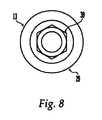
- FIG. 8is an end view of a cannulated screw
- FIG. 9is an exploded side view of a cannulated screw
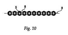
- FIG. 10is an overhead view of a reconstruction plate
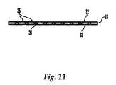
- FIG. 11is a side view of a reconstruction plate
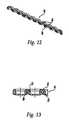
- FIG. 12is a cross-sectional view of a reconstruction plate
- FIG. 13is a partial side view of a reconstruction plate.
- the sternal reconstruction system of the present inventioncomprises a flexible cable with crimp, optionally one or more cannulated screws and optionally one or more reconstruction plates.
- simple circumferential or parasternal fixationmay be provided by use of a sternal reconstruction system comprising a flexible cable and ferrule.
- fixationmay be achieved by use of a sternal reconstruction system comprising a flexible cable, crimp and cannulated screws.
- fixationmay be achieved by use of a sternal reconstruction system comprising a flexible cable, crimp, cannulated screws and one or more reconstruction plates.
- FIGS. 1 to 3A first illustrative embodiment of a sternal reconstruction system is shown in FIGS. 1 to 3 .
- the sternal reconstruction system shown in FIG. 1comprises a flexible cable 1 having two ends, a first end A having attached thereto a crimp fitting 2 , and a second end B consisting of a thermally fused end 8 .
- Thermally fused end 8may assist in threading flexible cable 1 through the other elements of the sternal reconstruction system, and may also assist in preventing unraveling of flexible cable 1 .
- Flexible cable 1can be a single strand wire or a multi-wire stranded cable having from about 2 to about 1000 strands, preferably from about 50 to about 300 strands and most preferably from about 110 to about 145 strands, and has first and second ends A, B.
- Flexible cable 1may have any suitable degree of flexibility from highly flexible like yarn to stiff like wire. The flexible cable 1 , however, is sufficiently flexible to readily conform to the sternum, while sufficiently rigid to be manipulated as required.
- Flexible cable 1is typically attached to crimp fitting 2 by crimping the fitting onto the cable.
- Crimp fitting 2may be constructed from any suitable bio-compatible material, including, but not limited to, titanium, alloys of titanium, stainless steel and resorbable materials, although one of ordinary skill in the art will know and appreciate that any biocompatible material may be used.
- Crimp fitting 2preferably comprises a preinstalled flattened disk-like crimp head 3 having an upper surface 4 and a lower surface 5 .
- Upper surface 4may be flat or curved and optionally has rounded edges.
- Lower surface 5preferably is designed so as to mate with the top surface of a cannulated screw and/or a reconstruction plate, resulting in greater stability and/or a low profile.
- the flat lower surface 5may assist in stabilizing the crimp fitting to a bone anchor, such as a screw, or to a bone plate, and results in greater stability of the system.
- the flat lower surfacehelps provide a low profile to the crimp fitting.
- Crimp head 3has a diameter of from about 2 mm to about 10 mm, preferably about 6 mm, and a thickness of from about 0.1 mm to about 4 mm, preferably about 2 mm. While crimp head 3 is preferably a round disk, it may have other shapes such as square, rectangular or other polygon shape. Crimp head 3 has a diametrical hole or bore 6 through which the second or thermally fused end 8 of the flexible cable 1 is passed for attachment after the cable 1 is looped around the sternum. Diametric hole or bore 6 is sized so as to be able to accommodate the flexible cable 1 , and preferably has a diameter of from about 0.7 mm to about 2.5 mm, and more preferably about 1 mm.
- Crimp fitting 2further comprises a crimp shaft 7 that extends generally perpendicular to lower surface 4 .
- Crimp shaft 7may be cylindrically shaped, or have a non-circular cross-section.
- the crimp shaft 7may be a cylindrical tube which has an opening that receives the first end A of the flexible cable 1 .
- the cylindrical tubemay thereafter be crimped to attach the flexible cable 1 to the crimp fitting 2 .
- the crimping process of the crimp shaft 7may form a non-circular shape in the crimp shaft 7 , or other desired shape.
- the crimp shaft 7is located on the lower surface 4 of the crimp head such that the perimeter of the lower surface 4 of the crimp head surrounds the crimp shaft 7 in order to provide an annular bearing surface C.
- Annular bearing surface Chas a width of from about 0.5 mm to about 3 mm.
- the crimp shaft 7projects perpendicularly from the lower surface 4 of the crimp head 3 .
- Crimp shaft 7preferably is sized and shaped so as to fit within a cannulated screw or a bone plate. The non-circular cross-section of the crimp shaft 7 may engage the non-circular recess formed in a cannulated screw to prevent rotation of crimp fitting 2 in the cannulated screw.
- Crimp shaft 7preferably may range in size from about 0.7 mm to about 4 mm in diameter, more preferably about 2.5 mm, and from about 1.5 mm to about 4 mm in length, more preferably about 3 mm.
- the diameter of crimp shaft 7should not be less than the diameter of flexible cable 1 .
- the length and shape of crimp shaft 7may assist in stabilizing the crimp fitting 2 to a bone anchor, such as a screw, or to a bone plate, and results in greater stability of the system.
- FIG. 2shows an end view, partial cross-section of the upper face 4 of the crimp fitting 2 .
- Diametric hole 6may have an included counter sink region D on both sides of the crimp head 3 where it opens to the exterior.
- FIG. 3Ashows an end view of a cylindrical ferrule 9 which contains a hole 10 along its longitudinal axis.
- FIG. 3Bshows a side view of the ferrule.
- the hole 10 along the longitudinal axis of the ferrule 9is sized so as to accommodate the flexible cable 1 .
- the inner diameter of the ferrule 9may have a sharp edge in order to facilitate the cutting of the flexible cable 1 during crimping of the ferrule 9 onto the flexible cable 1 .
- Ferrule 9may be constructed from any suitable bio-compatible material, including, but not limited to, titanium, alloys of titanium, stainless steel and resorbable materials, although one of ordinary skill in the art will know and appreciate that any biocompatible material may be used.
- cylindrical ferrule 9can be crimped onto the flexible cable 1 after flexible cable 1 is drawn through diametric hole 6 to a predetermined tension.
- the ferrule 9preferably is sized so that it can not fit through the diametric hole 6 , preferably at least after it is crimped onto the flexible cable 1 .
- ferrule 9may be secured onto the flexible cable 1 by an adhesive.
- flexible cable 1 and/or ferrule 9are constructed from resorbable materials, and ferrule 9 may be secured onto the flexible cable 1 by thermal fusing.
- FIG. 4Another illustrative embodiment of a sternal reconstruction system is shown in FIG. 4 .
- the second or thermally fused end 8 of the flexible cable 1may be attached to a suture or needle 11 .
- the suture 11may typically be removed following its use, and is designed to be removed while preserving the fused end of the cable 1 .
- the suture 11may be constructed from any suitable bio-compatible material, including, but not limited to, titanium, alloys of titanium and stainless steel, although one of ordinary skill in the art will know and appreciate that any biocompatible material may be used.
- the flexible cable 1 and crimp fitting 2may be used to reapproximate, or secure together, two or more parts of a sternum by placing the crimp fitting 2 against a sternum to be mended and the flexible cable 1 wound around the separate portions of the sternum.
- the second or thermally fused end 8 of the flexible cable 1 to be attached to the crimp fitting 2is pulled to bring the flexible cable 1 taut around the sternum, thus reapproximating the separated parts of the sternum.
- the second or thermally fused end 8 of the flexible cable 1is passed through the diametrical hole 6 , and the flexible cable 1 is pulled taut.
- the tensioning of the flexible cable 1may be carried out, for example, by use of a safety cable tool.
- the flexible cable 1is secured in place by the ferrule 9 .
- Attachment of the ferrule 9 to the flexible cable 1may be carried out, for example, by crushing with pliers or any suitable crimping instrument.
- a cylindrical ferrule 9FIG. 3
- the flexible cable 1has a diameter of from about 0.7 mm to about 2.5 mm. Typically, if the flexible cable 1 is constructed of non-resorbable materials, it has a diameter of from about 0.7 mm to about 1.5 mm. Preferably flexible cable 1 has a diameter of about 1 mm. In one embodiment of the invention the flexible cable is Cerclage wire.
- the flexible cable 1may be of any suitable length, and is preferably from about 10 cm to about 1.5 m in length.
- Flexible cable 1may be constructed from any suitable bio-compatible material, including, but not limited to, titanium, alloys of titanium, stainless steel and resorbable materials, although one of ordinary skill in the art will know and appreciate that any biocompatible material may be used.
- FIGS. 5 and 6show a safety cable tool.
- the safety cable toolcan be used for tensioning the flexible cable or wire 1 used with the sternal reconstruction system.
- the toolcan be used to grasp and pull a flexible cable 1 to a predetermined tension limit. At the predetermined tension, the tool can be used to crimp a ferrule 9 to secure the flexible cable 1 .
- the toolmay also be used to sever the unused portion of flexible cable 1 .
- the crimping and severing processesmay be carried out independently or simultaneously, and manually or automatically.
- FIG. 5shows a ferrule 20 seated in aperture 21 of the safety cable tool.
- a cable 12 with free end 24is passed through the ferrule and through a clamping assembly 26 connected to a reciprocal arm 34 .
- the cable 12is also connected to a second clamping assembly 38 .
- the clamping assembliesinclude pawls 28 and 40 , which allow movement of the cable only in the direction of the cable's free end 24 .
- FIG. 6shows an exploded perspective of the safety cable tool.
- handle 36pivots about pin 80 and forces pin 70 to move upwards.
- arm 68rotates clockwise about pin 110 and arm 72 rotates counterclockwise about pin 88 , forcing pins 88 and 110 apart.
- Pin 110is linked to reciprocal arm 34 .
- pressureis applied to move reciprocal arm 34 against the bias of spring 58 , putting tension on cable 12 .
- pin 110will move no farther and depressing handle 36 forces pin 88 to move toward the aperture 21 .
- Pin 110is also linked to a plunger 94 such that when pin 88 is forced in the direction of the aperture 21 , plunger end 94 A is pushed into aperture 21 , thereby crimping the ferrule 20 about the cable 12 and simultaneously cutting cable 12 on the free end side of the ferrule.
- Suitable safety cable toolsare commercially available from Daniels Manufacturing Corporation and are described in U.S. Pat. Nos. 5,320,663; 5,345,663; and 5,361,475, the contents of which are incorporated herein in their entirety.
- one end of the cable 1comprises a preinstalled flattened round crimp fitting 2 with a diametrical hole 6 through which the second or thermally fused end 8 of the flexible cable 1 may pass after the cable 1 is looped around the sternum or passes through the cannulated screw 13 .
- the separated parts of the sternummay be reapproximated by tensioning the flexible cable 1 to a desired tension, and securing the cable 1 by crimping.
- a cylindrical ferrule 9may be crimped onto flexible cable 1 after the cable 1 is drawn through a cannulated screw and the diametric hole 6 in crimp fitting 2 to the preselected desired tension.
- the safety cable tool described abovemay be used to achieve such tensioning and crimping.
- the sternal reconstruction systemcomprises flexible cable 1 , crimp fitting 2 and at least one cannulated screw 13 .
- FIG. 7shows cannulated screw 13 , having a shaft 14 that is at least partially threaded for attachment to bone.
- the length of shaft 14 and the shaft thread configurationis selected to be suitable for use in the sterna.
- the threads and a tip 15can be made to be self-tapping and/or self-drilling to facilitate implantation.
- Shaft 14has a diameter of from about 1 mm to about 5 mm, and is cannulated with a channel or throughbore 16 for receiving the flexible cable 1 to aid in fixation of the sternum.
- the diameter of throughbore 16is preferably from about 0.7 mm to about 2.5 mm, and more preferably about 1 mm.
- the head 29 of the cannulated screw 13preferably has a flat or curved under surface 31 which will bear against a reconstruction plate (if used) or the anterior side of the sternum.
- FIGS. 8 and 9Further illustrative embodiment of a cannulated screw 13 are shown in FIGS. 8 and 9 .
- the head 29 of the cannulated screw 13may comprise an internal hex 30 for receiving an installation tool.
- An installation tool for use in drilling a hole in bone and for driving any of a variety of cannulated fasteners into the drilled holeis further described in pending U.S. application Ser. No. ______ entitled “Adjustable Tool for Cannulated Fasteners,” by Ciccone et al., which is incorporated by reference herein in its entirety.
- FIG. 9shows a cross-sectional view of cannulated screw 13 , and shows that the head 29 of the cannulated screw 13 comprises a hollow aperture 15 , while the shaft of the cannulated screw 13 is cannulated with a throughbore 16 which may receive the flexible cable 1 .
- the head 29 of the cannulated screw 13has a top surface that may be curved, substantially flat or other complex geometry.
- the lower surface 4 of the crimp fitting 2has a geometry that compliments the top surface of the screw 13 or reconstruction plate 18 to assist in stabilizing the crimp fitting 2 in location on the screw 13 or reconstruction plate 18 .
- the hollow aperture 15is preferably sized and shaped so as to accommodate crimp shaft 7 . The matching of the size and shape of crimp shaft 7 to the hollow aperture 15 may result in greater stability of the crimp fitting 2 in the screw 13 , particularly if there is a close fit between the shaft 7 and aperture 15 . In this manner the crimp shaft 7 may act as a journal inside the screw aperture 15 .
- the flat lower surface 5 of the crimp fitting 2preferably sits flush to the head of the cannulated screw 13 , and also provides stability to the system.
- any surgical screw as described above, having a threaded or a non-threaded head 17 of an appropriate size and geometry for select plate holes of the bone platecan be used.
- the head 29 of cannulated screw 13may be configured to lock with an optimally supplied bone plate or to be a non-locking screw.
- the head 29 of cannulated screw 13has a diameter of from about 2 mm to about 10 mm, and preferably about 6 mm.
- the cannulated screws 13may be constructed from any suitable bio-compatible material, including, but not limited to, titanium, alloys of titanium, stainless steel and resorbable materials, although one of ordinary skill in the art will know and appreciate that any biocompatible material may be used.
- the cannulated screws 13may be of any suitable length, and are typically from about 5 mm to about 24 mm in length. The skilled artisan will know that a screw 13 should be selected preferably so as to have a length such that, on use in sternal reconstruction, the tip of screw 13 will extend up to the posterior surface of the sternum, but preferably will not protrude to an undesirable distance from the posterior of the sternum.
- the cannulated screws 13are inserted into the sternum on opposite sides of the sternal fragments.
- Flexible cable or wire 1is fed through the lumen 16 of the cannulated screws 13 , and is tensioned to a desired tension, causing the portions of the sternum to be brought together.
- the tensioned flexible cable 1is secured to secure the aligned sternum.
- the cannulated screws 13prevent the flexible cable or wire 1 from bearing directly on the soft bone of the sternum, thus alleviating the clinical problems of “cut through” and sternal dehiscence, or separation of the bony sternum and manubrium following median sternotomy.
- the sternal reconstruction systemcomprises flexible cable 1 , crimp fitting 2 , cannulated screws 13 and at least one bone reconstruction plate 18 .
- FIGS. 10 to 13show illustrative embodiments of the reconstruction plate 12 .
- FIG. 10shows a top view of reconstruction plate 18 , having a generally rectangular cross section. However, any suitable configuration for the reconstruction plate 18 could be used.
- the reconstruction plate 18has a longitudinal axis 19 , upper and lower surfaces 22 , 23 , at least one plate hole 25 disposed generally perpendicularly to the longitudinal axis 19 of the reconstruction plate 18 , and at least one plate hole or bore 26 disposed transverse to the generally perpendicularly disposed plate hole 25 .
- perpendicular plate holes 25are each independently angled at a solid angle of from 0° to about 30° from normal to the upper and lower surfaces of the plate 18 .
- perpendicular plate holes 25are each independently angled at an angle of from 0° to about 30° from normal to the upper and lower surfaces of the plate 18 and along longitudinal axis 19 .
- generally perpendicular holes 25are normal to the upper and lower surfaces of the plate 18 , i.e., at 0°.
- Transverse plate holes or bores 26are each independently angled at a solid angle of from 0° to about 30° from normal to the side surfaces of the plate 18 .
- transverse plate holes or bores 26are each independently angled at an angle of from 0° to about 30° from normal to the side surfaces of the plate 18 and transverse to longitudinal axis 19 . Most preferably, transverse holes or bores 26 are normal to the side surfaces of the plate 18 , i.e., at 0°.
- Reconstruction plate 18has a length of from about 30 mm to about 250 mm, more preferably from about 80 mm to about 200 mm; a width of from about 5 mm to about 20 mm, more preferably from about 6 mm to about 10 mm; and a thickness of from about 0.5 mm to about 10 mm, more preferably from about 2 mm to about 4 mm.
- Plate holes 25extend from the upper surface 22 through the lower surface 23 of the reconstruction plate, and can be optionally used for accommodating fasteners, e.g. cannulated screws 13 , pins, and/or flexible cable 1 , to secure the reconstruction plate 18 to the sternum.
- fastenerse.g. cannulated screws 13 , pins, and/or flexible cable 1
- Plate holes 26extend transversely through the longitudinal axis 19 of the reconstruction plate 18 , and can optionally also be used for accommodating fasteners, e.g. cannulated screws and/or flexible cable, to secure the reconstruction plate to the sternum.
- the transverse holes 26are preferably located between generally perpendicular holes 25 .
- Any suitable combination of fastenerssuch as, for example, cannulated screws 13 or other screws, blades, nails, pins, etc. may be used to secure the reconstruction plate 18 to the sternum; for example, in one embodiment, bone anchors may be used solely with the generally perpendicular plate holes 25 , while in another embodiment flexible cable such as cable 1 and crimp fitting 2 solely may be used with the transverse plate holes 25 .
- a combination of generally perpendicular and transverse plate holes 25 , 26is selected so as to give optimum local securing of the reconstruction plates 18 .
- the reconstruction plate 18comprises a plurality of plate holes 25 disposed generally perpendicularly to the longitudinal axis 19 of the reconstruction plate 18 , and a plurality of plate holes 26 disposed transverse to the generally perpendicularly disposed plate holes 25 .
- the reconstruction plates 18may be constructed from any suitable bio-compatible material, including, but not limited to, titanium, alloys of titanium, stainless steel, resorbable materials, radio-translucent materials, allograft materials and resorbable materials, although one of ordinary skill in the art will know and appreciate that any biocompatible material may be used.
- the reconstruction plates 18may comprise a plurality of generally perpendicular plate holes 25 which pass through the upper and lower surfaces of plate 18 and are generally perpendicular to the longitudinal axis for receiving bone anchors.
- the reconstruction plates 18may further comprise a plurality of holes or bores 26 disposed generally transversely to the generally perpendicularly disposed plate holes 25 .
- the reconstruction plates 18comprise from about 2 to about 26 generally perpendicular plate holes 25 and from about 1 to about 25 transverse holes or bores 26 .
- the generally perpendicular plate holes 25are generally uniform in shape and size, and preferably are circular holes with a diameter of from about 2 mm to about 9 mm, more preferably from about 4 mm to about 6 mm. In another embodiment the holes may be oblong and may be ramped to provide compression.
- the generally perpendicular plate holesmay be configured to lock with an optionally supplied bone fastener.
- FIG. 11which shows a side view of reconstruction plate 18 , the transverse plate holes 26 are disposed between adjacent generally perpendicular plate holes 25 .
- FIG. 12shows a cross-sectional view of reconstruction plate 18 , wherein the location of the transverse plate holes 26 between adjacent generally perpendicular holes 25 can be seen.
- Transverse plate holes 26typically have a diameter smaller than that of the generally perpendicular holes 25 .
- the transverse plate holes 26have a diameter of from about 0.7 mm to about 2.5 mm, and more preferably about 1 mm.
- the diameter of the transverse plate holes 26preferably is selected so as to accommodate the flexible cable 1 .
- the reconstruction plate 18is counter-bored at the location of each transverse hole 26 .
- FIG. 13shows a side view of a reconstruction plate 18 , with transverse hole 26 and counter-bore 27 .
- both the generally perpendicular plate holes 25 and transverse plate holes 26may be round and cylindrical. This preferred geometry minimizes the change in material properties in the areas near the plate holes.
- generally perpendicular plate holes 25are countersunk toward either the upper or the lower surface 22 , 23 of the reconstruction plate 18 .
- the generally perpendicular plate holes 25are countersunk toward both the upper and the lower surface 22 , 23 of the reconstruction plate 18 .
- Countersunk generally perpendicular plate holes 25better accommodate the heads of the cannulated bone screws 13 , resulting in a highly stable system.
- the countersinksare in the shape of a cone.
- the upper and lower surfaces 22 , 23 of the reconstruction plate 18are planar. Because of the symmetry of the bone plate 18 , the bone plate 18 can be attached with either upper or lower surface 22 , 23 facing the bone with identical clinical results. In a preferred embodiment, at least one reconstruction plate 18 is attached to the sternum on opposite sides of the sternal fragments.
- the use of flexible cable 1 , reconstruction plates 18 and cannulated screws 13may be necessary in more complicated sternal reconstruction procedures, such as procedures wherein both midline and transverse fractures must be addressed.
- the reconstruction plates 18can be attached to each side of the split sternum by cannulated screws 13 .
- Flexible cable or wire 1may then be used to align and reduce the sternum. If transverse fractures are present, the reconstruction plates 18 function to reduce such fractures.
- one end of the flexible cable 1comprises a preinstalled flattened round crimp fitting 2 with a diametrical hole or bore 6 through which the second or thermally fused end 8 of the flexible cable 1 may pass after the flexible cable 1 is looped around the sternum or passes through the cannulated screws 13 and/or through the reconstruction plates 18 and throughbores 16 of the cannulated screws 13 .
- the separated parts of the sternummay be reapproximated by tensioning the flexible cable 1 to a desired tension, and securing the flexible cable 1 by crimping.
- a cylindrical ferrule 9may be crimped onto flexible cable 1 after the cable 1 is drawn through the hole 6 in crimp fitting 2 to the preselected desired tension.
- the safety cable tool described abovemay be used to achieve such tensioning and crimping.
- the present inventionalso relates to a sternal reconstruction kit which comprises at least one flexible cable 1 , at least one or more cannulated screws 13 and at least one or more reconstruction plates 18 .
- the kitmay contain at least one flexible cable 1 , wherein the second or thermally fused end 8 of the flexible cable 1 may be attached to a suture 11 .
- the kitmay optionally comprise a plurality of sizes of cannulated screws 13 and/or a plurality of sizes of reconstruction plates 18 .
- the reconstruction kitcomprises at least one ferrule 9 .
- the inner diameter of the ferrule 9may have a sharp edge in order to facilitate the cutting of the flexible cable 1 during crimping of the ferrule 9 onto the flexible cable 1 .
Landscapes
- Health & Medical Sciences (AREA)
- Orthopedic Medicine & Surgery (AREA)
- Surgery (AREA)
- Life Sciences & Earth Sciences (AREA)
- Heart & Thoracic Surgery (AREA)
- Nuclear Medicine, Radiotherapy & Molecular Imaging (AREA)
- Engineering & Computer Science (AREA)
- Biomedical Technology (AREA)
- Medical Informatics (AREA)
- Molecular Biology (AREA)
- Animal Behavior & Ethology (AREA)
- General Health & Medical Sciences (AREA)
- Public Health (AREA)
- Veterinary Medicine (AREA)
- Neurology (AREA)
- Surgical Instruments (AREA)
- Prostheses (AREA)
Abstract
Description
Claims (53)
Priority Applications (14)
| Application Number | Priority Date | Filing Date | Title |
|---|---|---|---|
| US10/830,130US7704252B2 (en) | 2004-04-21 | 2004-04-21 | Sternal reconstruction system |
| BRPI0510055ABRPI0510055B1 (en) | 2004-04-21 | 2005-04-21 | sternum reconstruction system, flex, and method and assembly for sternum reconstruction |
| KR1020067024354AKR101185942B1 (en) | 2004-04-21 | 2005-04-21 | Sternal reconstruction system |
| CA2564799ACA2564799C (en) | 2004-04-21 | 2005-04-21 | Sternal reconstruction system |
| CN2005800201565ACN101005809B (en) | 2004-04-21 | 2005-04-21 | Sternal reconstruction system |
| PCT/US2005/013599WO2005104967A2 (en) | 2004-04-21 | 2005-04-21 | Sternal reconstruction system |
| JP2007509626AJP4945439B2 (en) | 2004-04-21 | 2005-04-21 | Sternum repair system |
| AU2005237491AAU2005237491A1 (en) | 2004-04-21 | 2005-04-21 | Sternal reconstruction system |
| EP05738787.0AEP1740110B1 (en) | 2004-04-21 | 2005-04-21 | Sternal reconstruction system |
| ZA200608988AZA200608988B (en) | 2004-04-21 | 2005-04-21 | Sternal reconstruction system |
| US11/152,738US9055984B2 (en) | 2004-04-21 | 2005-06-13 | Sternal reconstruction system |
| US12/721,181US8419736B2 (en) | 2004-04-21 | 2010-03-10 | Sternal reconstruction system |
| JP2011272716AJP2012055718A (en) | 2004-04-21 | 2011-11-25 | Sternal reconstruction system |
| US13/796,209US9295507B2 (en) | 2004-04-21 | 2013-03-12 | Sternal reconstruction system |
Applications Claiming Priority (1)
| Application Number | Priority Date | Filing Date | Title |
|---|---|---|---|
| US10/830,130US7704252B2 (en) | 2004-04-21 | 2004-04-21 | Sternal reconstruction system |
Related Child Applications (2)
| Application Number | Title | Priority Date | Filing Date |
|---|---|---|---|
| US11/152,738Continuation-In-PartUS9055984B2 (en) | 2004-04-21 | 2005-06-13 | Sternal reconstruction system |
| US12/721,181DivisionUS8419736B2 (en) | 2004-04-21 | 2010-03-10 | Sternal reconstruction system |
Publications (2)
| Publication Number | Publication Date |
|---|---|
| US20050240198A1 US20050240198A1 (en) | 2005-10-27 |
| US7704252B2true US7704252B2 (en) | 2010-04-27 |
Family
ID=35137473
Family Applications (3)
| Application Number | Title | Priority Date | Filing Date |
|---|---|---|---|
| US10/830,130Active2027-06-17US7704252B2 (en) | 2004-04-21 | 2004-04-21 | Sternal reconstruction system |
| US12/721,181Expired - Fee RelatedUS8419736B2 (en) | 2004-04-21 | 2010-03-10 | Sternal reconstruction system |
| US13/796,209Expired - Fee RelatedUS9295507B2 (en) | 2004-04-21 | 2013-03-12 | Sternal reconstruction system |
Family Applications After (2)
| Application Number | Title | Priority Date | Filing Date |
|---|---|---|---|
| US12/721,181Expired - Fee RelatedUS8419736B2 (en) | 2004-04-21 | 2010-03-10 | Sternal reconstruction system |
| US13/796,209Expired - Fee RelatedUS9295507B2 (en) | 2004-04-21 | 2013-03-12 | Sternal reconstruction system |
Country Status (10)
| Country | Link |
|---|---|
| US (3) | US7704252B2 (en) |
| EP (1) | EP1740110B1 (en) |
| JP (2) | JP4945439B2 (en) |
| KR (1) | KR101185942B1 (en) |
| CN (1) | CN101005809B (en) |
| AU (1) | AU2005237491A1 (en) |
| BR (1) | BRPI0510055B1 (en) |
| CA (1) | CA2564799C (en) |
| WO (1) | WO2005104967A2 (en) |
| ZA (1) | ZA200608988B (en) |
Cited By (10)
| Publication number | Priority date | Publication date | Assignee | Title |
|---|---|---|---|---|
| US20050240191A1 (en)* | 2004-04-21 | 2005-10-27 | Thomas Albertson | Sternal reconstruction system |
| US20060167464A1 (en)* | 2004-09-23 | 2006-07-27 | Allen C W | Systems, methods, and apparatuses for tensioning an orthopedic surgical cable |
| US20100168804A1 (en)* | 2004-04-21 | 2010-07-01 | Synthes Usa, Llc | Sternal Reconstruction System |
| US8992530B2 (en) | 2012-01-10 | 2015-03-31 | The Charlotte-Mecklenburg Hospital Authority | Method and system for longitudinal closure of dissected sternums |
| US9011501B2 (en) | 2011-12-14 | 2015-04-21 | DePuy Synthes Products, Inc. | Device for compression across fractures |
| US9517096B2 (en) | 2012-01-10 | 2016-12-13 | The Charlotte-Mecklenburg Hospital Authority | Method and system for longitudinal closure of dissected sternums |
| US9788862B2 (en) | 2014-05-12 | 2017-10-17 | DePuy Synthes Products, Inc. | Sacral fixation system |
| US10064670B2 (en) | 2014-05-12 | 2018-09-04 | DePuy Synthes Products, Inc. | Sacral fixation system |
| US10201376B2 (en) | 2013-02-27 | 2019-02-12 | Biomet C.V. | Periprosthetic plating system including plate with system for retaining tension on a cable |
| US11395688B2 (en) | 2019-09-30 | 2022-07-26 | DePuy Synthes Products, Inc. | Tool for crimping orthopedic cable |
Families Citing this family (75)
| Publication number | Priority date | Publication date | Assignee | Title |
|---|---|---|---|---|
| US8303604B2 (en) | 2004-11-05 | 2012-11-06 | Biomet Sports Medicine, Llc | Soft tissue repair device and method |
| US7905904B2 (en) | 2006-02-03 | 2011-03-15 | Biomet Sports Medicine, Llc | Soft tissue repair device and associated methods |
| US7658751B2 (en) | 2006-09-29 | 2010-02-09 | Biomet Sports Medicine, Llc | Method for implanting soft tissue |
| US8118836B2 (en) | 2004-11-05 | 2012-02-21 | Biomet Sports Medicine, Llc | Method and apparatus for coupling soft tissue to a bone |
| US8137382B2 (en) | 2004-11-05 | 2012-03-20 | Biomet Sports Medicine, Llc | Method and apparatus for coupling anatomical features |
| US8840645B2 (en) | 2004-11-05 | 2014-09-23 | Biomet Sports Medicine, Llc | Method and apparatus for coupling soft tissue to a bone |
| US7749250B2 (en) | 2006-02-03 | 2010-07-06 | Biomet Sports Medicine, Llc | Soft tissue repair assembly and associated method |
| US9017381B2 (en) | 2007-04-10 | 2015-04-28 | Biomet Sports Medicine, Llc | Adjustable knotless loops |
| US7857830B2 (en) | 2006-02-03 | 2010-12-28 | Biomet Sports Medicine, Llc | Soft tissue repair and conduit device |
| US8128658B2 (en) | 2004-11-05 | 2012-03-06 | Biomet Sports Medicine, Llc | Method and apparatus for coupling soft tissue to bone |
| US8361113B2 (en) | 2006-02-03 | 2013-01-29 | Biomet Sports Medicine, Llc | Method and apparatus for coupling soft tissue to a bone |
| US7909851B2 (en) | 2006-02-03 | 2011-03-22 | Biomet Sports Medicine, Llc | Soft tissue repair device and associated methods |
| US9801708B2 (en) | 2004-11-05 | 2017-10-31 | Biomet Sports Medicine, Llc | Method and apparatus for coupling soft tissue to a bone |
| US8298262B2 (en) | 2006-02-03 | 2012-10-30 | Biomet Sports Medicine, Llc | Method for tissue fixation |
| US8088130B2 (en) | 2006-02-03 | 2012-01-03 | Biomet Sports Medicine, Llc | Method and apparatus for coupling soft tissue to a bone |
| US8998949B2 (en) | 2004-11-09 | 2015-04-07 | Biomet Sports Medicine, Llc | Soft tissue conduit device |
| US8652172B2 (en) | 2006-02-03 | 2014-02-18 | Biomet Sports Medicine, Llc | Flexible anchors for tissue fixation |
| US9149267B2 (en) | 2006-02-03 | 2015-10-06 | Biomet Sports Medicine, Llc | Method and apparatus for coupling soft tissue to a bone |
| US8574235B2 (en) | 2006-02-03 | 2013-11-05 | Biomet Sports Medicine, Llc | Method for trochanteric reattachment |
| US8801783B2 (en) | 2006-09-29 | 2014-08-12 | Biomet Sports Medicine, Llc | Prosthetic ligament system for knee joint |
| US9468433B2 (en) | 2006-02-03 | 2016-10-18 | Biomet Sports Medicine, Llc | Method and apparatus for forming a self-locking adjustable loop |
| US8506597B2 (en) | 2011-10-25 | 2013-08-13 | Biomet Sports Medicine, Llc | Method and apparatus for interosseous membrane reconstruction |
| US8562645B2 (en) | 2006-09-29 | 2013-10-22 | Biomet Sports Medicine, Llc | Method and apparatus for forming a self-locking adjustable loop |
| US8771352B2 (en) | 2011-05-17 | 2014-07-08 | Biomet Sports Medicine, Llc | Method and apparatus for tibial fixation of an ACL graft |
| US9538998B2 (en) | 2006-02-03 | 2017-01-10 | Biomet Sports Medicine, Llc | Method and apparatus for fracture fixation |
| US8251998B2 (en) | 2006-08-16 | 2012-08-28 | Biomet Sports Medicine, Llc | Chondral defect repair |
| US9271713B2 (en) | 2006-02-03 | 2016-03-01 | Biomet Sports Medicine, Llc | Method and apparatus for tensioning a suture |
| US10517587B2 (en) | 2006-02-03 | 2019-12-31 | Biomet Sports Medicine, Llc | Method and apparatus for forming a self-locking adjustable loop |
| US8597327B2 (en) | 2006-02-03 | 2013-12-03 | Biomet Manufacturing, Llc | Method and apparatus for sternal closure |
| US8652171B2 (en) | 2006-02-03 | 2014-02-18 | Biomet Sports Medicine, Llc | Method and apparatus for soft tissue fixation |
| US8562647B2 (en) | 2006-09-29 | 2013-10-22 | Biomet Sports Medicine, Llc | Method and apparatus for securing soft tissue to bone |
| US11311287B2 (en) | 2006-02-03 | 2022-04-26 | Biomet Sports Medicine, Llc | Method for tissue fixation |
| US11259792B2 (en) | 2006-02-03 | 2022-03-01 | Biomet Sports Medicine, Llc | Method and apparatus for coupling anatomical features |
| US9078644B2 (en) | 2006-09-29 | 2015-07-14 | Biomet Sports Medicine, Llc | Fracture fixation device |
| US8968364B2 (en) | 2006-02-03 | 2015-03-03 | Biomet Sports Medicine, Llc | Method and apparatus for fixation of an ACL graft |
| US8672969B2 (en) | 2006-09-29 | 2014-03-18 | Biomet Sports Medicine, Llc | Fracture fixation device |
| US11259794B2 (en) | 2006-09-29 | 2022-03-01 | Biomet Sports Medicine, Llc | Method for implanting soft tissue |
| US9918826B2 (en) | 2006-09-29 | 2018-03-20 | Biomet Sports Medicine, Llc | Scaffold for spring ligament repair |
| US8500818B2 (en) | 2006-09-29 | 2013-08-06 | Biomet Manufacturing, Llc | Knee prosthesis assembly with ligament link |
| US9345517B2 (en) | 2008-02-02 | 2016-05-24 | Globus Medical, Inc. | Pedicle screw having a removable rod coupling |
| US12419632B2 (en) | 2008-08-22 | 2025-09-23 | Biomet Sports Medicine, Llc | Method and apparatus for coupling anatomical features |
| US12245759B2 (en) | 2008-08-22 | 2025-03-11 | Biomet Sports Medicine, Llc | Method and apparatus for coupling soft tissue to bone |
| US8486114B2 (en) | 2008-10-10 | 2013-07-16 | Acute Innovations Llc | Cerclage system for bone |
| US9089377B2 (en) | 2009-02-23 | 2015-07-28 | Orthopediatrics Corp. | Bone screw |
| US8343227B2 (en) | 2009-05-28 | 2013-01-01 | Biomet Manufacturing Corp. | Knee prosthesis assembly with ligament link |
| US12096928B2 (en) | 2009-05-29 | 2024-09-24 | Biomet Sports Medicine, Llc | Method and apparatus for coupling soft tissue to a bone |
| BRPI1002494B1 (en)* | 2010-07-12 | 2015-08-18 | João Bosco De Oliveira | Shear with tensioning device |
| US12329373B2 (en) | 2011-05-02 | 2025-06-17 | Biomet Sports Medicine, Llc | Method and apparatus for soft tissue fixation |
| FR2981841B1 (en)* | 2011-10-28 | 2013-12-20 | Implanet | DEVICE FOR TENSIONING A SOFT BAND AND COMPRISING ASSEMBLY SUCH DEVICE WITH FLEXIBLE BAND |
| US11123117B1 (en)* | 2011-11-01 | 2021-09-21 | Nuvasive, Inc. | Surgical fixation system and related methods |
| US9357991B2 (en) | 2011-11-03 | 2016-06-07 | Biomet Sports Medicine, Llc | Method and apparatus for stitching tendons |
| US9381013B2 (en) | 2011-11-10 | 2016-07-05 | Biomet Sports Medicine, Llc | Method for coupling soft tissue to a bone |
| US9370350B2 (en) | 2011-11-10 | 2016-06-21 | Biomet Sports Medicine, Llc | Apparatus for coupling soft tissue to a bone |
| US9314241B2 (en) | 2011-11-10 | 2016-04-19 | Biomet Sports Medicine, Llc | Apparatus for coupling soft tissue to a bone |
| EP2830512B1 (en)* | 2012-03-28 | 2016-08-03 | Synthes GmbH | Bone fixation member systems |
| JP6105055B2 (en) | 2012-04-30 | 2017-03-29 | アキュート・イノヴェーションズ・エルエルシー | System for joining bones |
| US20140088647A1 (en)* | 2012-09-21 | 2014-03-27 | Atlas Spine, Inc. | Minimally invasive spine surgery instruments: spinal rod with flange |
| US9757119B2 (en) | 2013-03-08 | 2017-09-12 | Biomet Sports Medicine, Llc | Visual aid for identifying suture limbs arthroscopically |
| US9918827B2 (en) | 2013-03-14 | 2018-03-20 | Biomet Sports Medicine, Llc | Scaffold for spring ligament repair |
| US9820755B2 (en) | 2013-03-15 | 2017-11-21 | Zimmer Biomet CMF and Thoracic, LLC | Sternal closure cerclage, plate implant and instrumentation |
| US10010359B2 (en) | 2013-03-15 | 2018-07-03 | Zimmer Biomet CMF and Thoracic, LLC | Sternal closure cerclage, plate implant and instrumentation |
| US10136886B2 (en) | 2013-12-20 | 2018-11-27 | Biomet Sports Medicine, Llc | Knotless soft tissue devices and techniques |
| US9615822B2 (en) | 2014-05-30 | 2017-04-11 | Biomet Sports Medicine, Llc | Insertion tools and method for soft anchor |
| US9700291B2 (en) | 2014-06-03 | 2017-07-11 | Biomet Sports Medicine, Llc | Capsule retractor |
| US10039543B2 (en) | 2014-08-22 | 2018-08-07 | Biomet Sports Medicine, Llc | Non-sliding soft anchor |
| US20160143663A1 (en)* | 2014-11-24 | 2016-05-26 | Stryker European Holdings I, Llc | Strut plate and cabling system |
| US9955980B2 (en) | 2015-02-24 | 2018-05-01 | Biomet Sports Medicine, Llc | Anatomic soft tissue repair |
| US9974534B2 (en) | 2015-03-31 | 2018-05-22 | Biomet Sports Medicine, Llc | Suture anchor with soft anchor of electrospun fibers |
| CN105769322A (en)* | 2016-03-03 | 2016-07-20 | 邓宇 | T-Y cable for tying-up and fixation in case of bone fracture |
| DE102016011947A1 (en)* | 2016-10-05 | 2018-04-05 | Bluewater Medical GmbH | Screw with a head part, a threaded part and a connecting part |
| US9956021B1 (en)* | 2017-01-03 | 2018-05-01 | DePuy Synthes Products, Inc. | Tensioning and crimping tool for orthopedic cable tensioning |
| US10499972B2 (en) | 2017-01-03 | 2019-12-10 | DePuy Synthes Products, Inc. | Mini cable tensioner for orthopedic cable tensioning |
| CN112137671A (en)* | 2019-06-27 | 2020-12-29 | 青岛大学附属医院 | Percutaneous pedicle screw-assisted expandable hemostasis conical device |
| CN111658053B (en)* | 2020-07-02 | 2025-01-21 | 上海拓舜医疗科技有限公司 | A hemostatic buckle |
| CN111772760B (en)* | 2020-08-18 | 2021-07-27 | 西安康拓医疗技术股份有限公司 | Binding gun for sternal suture |
Citations (18)
| Publication number | Priority date | Publication date | Assignee | Title |
|---|---|---|---|---|
| US4682849A (en)* | 1981-09-16 | 1987-07-28 | Showa Electric Wire & Cable Co. Ltd. | Optical fiber junction and method of making same |
| US5190545A (en) | 1991-08-27 | 1993-03-02 | Pfizer Hospital Products Group, Inc. | Cerclage wire positioning insert |
| US5318566A (en) | 1992-06-22 | 1994-06-07 | Danek Medical, Inc. | Sternotomy cable and method |
| US5320663A (en) | 1992-07-02 | 1994-06-14 | E. I. Du Pont De Nemours And Company | Method of obtaining lead and organolead from contaminated media using metal accumulating plants |
| US5345663A (en) | 1992-02-05 | 1994-09-13 | Daniels Manufacturing Corporation | Safety cable tool |
| US5361475A (en) | 1992-02-05 | 1994-11-08 | Daniels Manufacturing Corporation | Safety cable tool |
| US5741260A (en)* | 1994-02-24 | 1998-04-21 | Pioneer Laboratories, Inc. | Cable system for bone securance |
| US5766218A (en)* | 1996-10-01 | 1998-06-16 | Metamorphic Surgical Devices, Inc. | Surgical binding device and method of using same |
| US5785712A (en) | 1996-04-16 | 1998-07-28 | Terray Corporation | Reconstruction bone plate |
| US5964769A (en)* | 1997-08-26 | 1999-10-12 | Spinal Concepts, Inc. | Surgical cable system and method |
| US6158437A (en)* | 1993-12-14 | 2000-12-12 | Vagley; Richard T. | Method of performing a surgical procedure and associated surgical instrument support tray |
| US6296643B1 (en) | 1999-04-23 | 2001-10-02 | Sdgi Holdings, Inc. | Device for the correction of spinal deformities through vertebral body tethering without fusion |
| US20020091391A1 (en)* | 1998-01-26 | 2002-07-11 | Orthodyne, Inc. | Tissue anchoring system and method |
| US6436123B1 (en) | 1998-01-13 | 2002-08-20 | Cardiacassist, Inc. | System apparatus and method for closing severed bone or tissue of a patient |
| US20050038428A1 (en)* | 2003-07-30 | 2005-02-17 | Kelman David C. | Methods and devices for retaining cerclage cable |
| US20050171547A1 (en)* | 2004-01-29 | 2005-08-04 | Aram Tony N. | Surgical instrument, and related methods |
| US20050222575A1 (en) | 2004-04-06 | 2005-10-06 | Paul Ciccone | Adjustable tool for cannulated fasteners |
| US7065267B2 (en)* | 2002-11-14 | 2006-06-20 | Finisar Corporation | Athermal fused coupler package for optical fibers |
Family Cites Families (39)
| Publication number | Priority date | Publication date | Assignee | Title |
|---|---|---|---|---|
| US3037619A (en) | 1959-11-16 | 1962-06-05 | Stevans Ernest | Suture devices |
| US3187752A (en) | 1962-04-27 | 1965-06-08 | American Cyanamid Co | Non-absorbable silicone coated sutures and method of making |
| US4683849A (en)* | 1984-11-20 | 1987-08-04 | Brown Arthur E | Reciprocating multicylinder vee machines with secondary counterbalancers |
| US4880002A (en) | 1985-05-30 | 1989-11-14 | Corvita Corporation | Stretchable porous sutures |
| JPS61296188A (en) | 1985-06-24 | 1986-12-26 | 旭化成株式会社 | System terminal treatment method |
| FR2614781B1 (en)* | 1987-05-05 | 1989-08-04 | Galline Yves | ATTACHMENT DEVICE AND TOOLS FOR ITS PLACEMENT, PARTICULARLY FOR ATTACHING THE GRAND TROCHANTER TO THE FEMUR |
| US6187752B1 (en)* | 1988-03-07 | 2001-02-13 | E.R. Squibb & Sons, Inc. | Method for treating schizophrenia employing an ace inhibitor |
| US4944753A (en) | 1988-09-26 | 1990-07-31 | Burgess Frank M | Method for producing retro-sternal space |
| US4966600A (en)* | 1989-01-26 | 1990-10-30 | Songer Robert J | Surgical securance method |
| US5061827A (en) | 1990-06-27 | 1991-10-29 | Amp Incorporated | Termination of a small coaxial cable |
| GB9206018D0 (en) | 1992-03-19 | 1992-04-29 | Dall Desmond Meiring | Bone fixation system |
| US5810825A (en)* | 1995-06-01 | 1998-09-22 | Huebner; Randall J. | Surgical wire clamp |
| US6120505A (en) | 1995-06-01 | 2000-09-19 | Acumed, Inc. | Wire clamp assembly |
| US5540698A (en)* | 1993-04-21 | 1996-07-30 | Amei Technologies Inc. | System and method for securing a medical cable |
| JP2987037B2 (en)* | 1993-08-09 | 1999-12-06 | 喜十郎 早野 | Wire fastener |
| US5395374A (en)* | 1993-09-02 | 1995-03-07 | Danek Medical, Inc. | Orthopedic cabling method and apparatus |
| US5417690A (en) | 1993-09-20 | 1995-05-23 | Codman & Shurtleff, Inc. | Surgical cable |
| US5415658A (en) | 1993-12-14 | 1995-05-16 | Pioneer Laboratories, Inc. | Surgical cable loop connector |
| US5423821A (en)* | 1994-01-18 | 1995-06-13 | Pasque; Michael K. | Sternal closure device |
| AU1967095A (en) | 1994-02-17 | 1995-09-04 | Surgical Accessories, Inc. | Fastener and tensioner for bone securing cable |
| US5569253A (en) | 1994-03-29 | 1996-10-29 | Danek Medical, Inc. | Variable-angle surgical cable crimp assembly and method |
| US5653711A (en) | 1994-08-08 | 1997-08-05 | Kijuro Hayano | Wire fastening tool |
| US5649927A (en) | 1995-09-27 | 1997-07-22 | Pioneer Laboratories, Inc. | Cable crimp system |
| US5702399A (en)* | 1996-05-16 | 1997-12-30 | Pioneer Laboratories, Inc. | Surgical cable screw connector |
| DE19628147C2 (en) | 1996-07-12 | 2003-02-20 | Aesculap Ag & Co Kg | Surgical device for fixing bone elements |
| US5810824A (en)* | 1997-02-13 | 1998-09-22 | Chan; Kwan-Ho | Surgical fastener assembly and method for bone fracture fixation |
| US6053921A (en)* | 1997-08-26 | 2000-04-25 | Spinal Concepts, Inc. | Surgical cable system and method |
| US5997542A (en)* | 1997-11-18 | 1999-12-07 | Biomet, Inc. | Surgical wire assembly and method of use |
| US5916217A (en) | 1998-01-06 | 1999-06-29 | Synthes (Usa) | Cranial spring clip |
| US7052499B2 (en)* | 1998-02-18 | 2006-05-30 | Walter Lorenz Surgical, Inc. | Method and apparatus for bone fracture fixation |
| US6317555B1 (en)* | 1998-05-06 | 2001-11-13 | Cidra Corporation | Creep-resistant optical fiber attachment |
| JP3056479B1 (en) | 1999-03-19 | 2000-06-26 | 株式会社ロバート・リード商会 | Implant connection wire-rod |
| WO2001005315A1 (en)* | 1999-07-19 | 2001-01-25 | Grampian University Hospitals Nhs Trust | Medical device |
| JP2001276084A (en) | 2000-03-30 | 2001-10-09 | Nippon Sogo Igaku Kenkyusho:Kk | Set for joining or straightening bone |
| JP2004092869A (en) | 2002-09-03 | 2004-03-25 | Osaka Coat Rope Kk | Method for forming loop with terminal part of wire, metal fixture used for the same, and hanger tool using metal fixture |
| US20040199169A1 (en) | 2002-11-20 | 2004-10-07 | Koons Kirk C. | Cable clamp tool for surgical applications |
| DE10333781B4 (en) | 2003-07-24 | 2007-04-19 | Webasto Ag | Openable vehicle roof |
| US9055984B2 (en) | 2004-04-21 | 2015-06-16 | DePuy Synthes Products, Inc. | Sternal reconstruction system |
| US7704252B2 (en) | 2004-04-21 | 2010-04-27 | Synthes Usa, Llc | Sternal reconstruction system |
- 2004
- 2004-04-21USUS10/830,130patent/US7704252B2/enactiveActive
- 2005
- 2005-04-21KRKR1020067024354Apatent/KR101185942B1/ennot_activeExpired - Fee Related
- 2005-04-21EPEP05738787.0Apatent/EP1740110B1/ennot_activeExpired - Lifetime
- 2005-04-21ZAZA200608988Apatent/ZA200608988B/enunknown
- 2005-04-21AUAU2005237491Apatent/AU2005237491A1/ennot_activeAbandoned
- 2005-04-21CNCN2005800201565Apatent/CN101005809B/ennot_activeExpired - Fee Related
- 2005-04-21BRBRPI0510055Apatent/BRPI0510055B1/ennot_activeIP Right Cessation
- 2005-04-21CACA2564799Apatent/CA2564799C/ennot_activeExpired - Fee Related
- 2005-04-21JPJP2007509626Apatent/JP4945439B2/ennot_activeExpired - Fee Related
- 2005-04-21WOPCT/US2005/013599patent/WO2005104967A2/enactiveApplication Filing
- 2010
- 2010-03-10USUS12/721,181patent/US8419736B2/ennot_activeExpired - Fee Related
- 2011
- 2011-11-25JPJP2011272716Apatent/JP2012055718A/enactivePending
- 2013
- 2013-03-12USUS13/796,209patent/US9295507B2/ennot_activeExpired - Fee Related
Patent Citations (20)
| Publication number | Priority date | Publication date | Assignee | Title |
|---|---|---|---|---|
| US4682849A (en)* | 1981-09-16 | 1987-07-28 | Showa Electric Wire & Cable Co. Ltd. | Optical fiber junction and method of making same |
| US5190545A (en) | 1991-08-27 | 1993-03-02 | Pfizer Hospital Products Group, Inc. | Cerclage wire positioning insert |
| US5345663A (en) | 1992-02-05 | 1994-09-13 | Daniels Manufacturing Corporation | Safety cable tool |
| US5361475A (en) | 1992-02-05 | 1994-11-08 | Daniels Manufacturing Corporation | Safety cable tool |
| US5318566A (en) | 1992-06-22 | 1994-06-07 | Danek Medical, Inc. | Sternotomy cable and method |
| US5320663A (en) | 1992-07-02 | 1994-06-14 | E. I. Du Pont De Nemours And Company | Method of obtaining lead and organolead from contaminated media using metal accumulating plants |
| US6158437A (en)* | 1993-12-14 | 2000-12-12 | Vagley; Richard T. | Method of performing a surgical procedure and associated surgical instrument support tray |
| US5741260A (en)* | 1994-02-24 | 1998-04-21 | Pioneer Laboratories, Inc. | Cable system for bone securance |
| US5785712A (en) | 1996-04-16 | 1998-07-28 | Terray Corporation | Reconstruction bone plate |
| US5766218A (en)* | 1996-10-01 | 1998-06-16 | Metamorphic Surgical Devices, Inc. | Surgical binding device and method of using same |
| US5964769A (en)* | 1997-08-26 | 1999-10-12 | Spinal Concepts, Inc. | Surgical cable system and method |
| US6391030B1 (en)* | 1997-08-26 | 2002-05-21 | Spinal Concepts, Inc. | Surgical cable system and method |
| US6436123B1 (en) | 1998-01-13 | 2002-08-20 | Cardiacassist, Inc. | System apparatus and method for closing severed bone or tissue of a patient |
| US20020091391A1 (en)* | 1998-01-26 | 2002-07-11 | Orthodyne, Inc. | Tissue anchoring system and method |
| US6544267B1 (en)* | 1998-01-26 | 2003-04-08 | Orthodyne, Inc. | Tissue anchoring system and method |
| US6296643B1 (en) | 1999-04-23 | 2001-10-02 | Sdgi Holdings, Inc. | Device for the correction of spinal deformities through vertebral body tethering without fusion |
| US7065267B2 (en)* | 2002-11-14 | 2006-06-20 | Finisar Corporation | Athermal fused coupler package for optical fibers |
| US20050038428A1 (en)* | 2003-07-30 | 2005-02-17 | Kelman David C. | Methods and devices for retaining cerclage cable |
| US20050171547A1 (en)* | 2004-01-29 | 2005-08-04 | Aram Tony N. | Surgical instrument, and related methods |
| US20050222575A1 (en) | 2004-04-06 | 2005-10-06 | Paul Ciccone | Adjustable tool for cannulated fasteners |
Non-Patent Citations (1)
| Title |
|---|
| Chase, C.W. et al., "Internal Fixation of the Sternum in Median Sternotomy Dehiscence," Plastic and Reconstructive Surgery, May 1999, 1667-1673. |
Cited By (15)
| Publication number | Priority date | Publication date | Assignee | Title |
|---|---|---|---|---|
| US9055984B2 (en) | 2004-04-21 | 2015-06-16 | DePuy Synthes Products, Inc. | Sternal reconstruction system |
| US20100168804A1 (en)* | 2004-04-21 | 2010-07-01 | Synthes Usa, Llc | Sternal Reconstruction System |
| US8419736B2 (en) | 2004-04-21 | 2013-04-16 | Synthes Usa, Llc | Sternal reconstruction system |
| US9295507B2 (en) | 2004-04-21 | 2016-03-29 | DePuy Synthes Products, Inc. | Sternal reconstruction system |
| US20050240191A1 (en)* | 2004-04-21 | 2005-10-27 | Thomas Albertson | Sternal reconstruction system |
| US20060167464A1 (en)* | 2004-09-23 | 2006-07-27 | Allen C W | Systems, methods, and apparatuses for tensioning an orthopedic surgical cable |
| US8469966B2 (en)* | 2004-09-23 | 2013-06-25 | Smith & Nephew, Inc. | Systems, methods, and apparatuses for tensioning an orthopedic surgical cable |
| US9011501B2 (en) | 2011-12-14 | 2015-04-21 | DePuy Synthes Products, Inc. | Device for compression across fractures |
| US9408637B2 (en) | 2011-12-14 | 2016-08-09 | DePuy Synthes Products, Inc. | Device for compression across fractures |
| US8992530B2 (en) | 2012-01-10 | 2015-03-31 | The Charlotte-Mecklenburg Hospital Authority | Method and system for longitudinal closure of dissected sternums |
| US9517096B2 (en) | 2012-01-10 | 2016-12-13 | The Charlotte-Mecklenburg Hospital Authority | Method and system for longitudinal closure of dissected sternums |
| US10201376B2 (en) | 2013-02-27 | 2019-02-12 | Biomet C.V. | Periprosthetic plating system including plate with system for retaining tension on a cable |
| US9788862B2 (en) | 2014-05-12 | 2017-10-17 | DePuy Synthes Products, Inc. | Sacral fixation system |
| US10064670B2 (en) | 2014-05-12 | 2018-09-04 | DePuy Synthes Products, Inc. | Sacral fixation system |
| US11395688B2 (en) | 2019-09-30 | 2022-07-26 | DePuy Synthes Products, Inc. | Tool for crimping orthopedic cable |
Also Published As
| Publication number | Publication date |
|---|---|
| BRPI0510055B1 (en) | 2017-06-06 |
| US20130190826A1 (en) | 2013-07-25 |
| KR101185942B1 (en) | 2012-09-25 |
| BRPI0510055A (en) | 2007-10-16 |
| CA2564799A1 (en) | 2005-11-10 |
| WO2005104967A3 (en) | 2006-12-14 |
| CN101005809A (en) | 2007-07-25 |
| US9295507B2 (en) | 2016-03-29 |
| US8419736B2 (en) | 2013-04-16 |
| CN101005809B (en) | 2012-02-01 |
| EP1740110A4 (en) | 2010-01-20 |
| AU2005237491A1 (en) | 2005-11-10 |
| KR20070017384A (en) | 2007-02-09 |
| JP2007533414A (en) | 2007-11-22 |
| US20050240198A1 (en) | 2005-10-27 |
| WO2005104967A2 (en) | 2005-11-10 |
| JP4945439B2 (en) | 2012-06-06 |
| JP2012055718A (en) | 2012-03-22 |
| EP1740110B1 (en) | 2016-07-27 |
| CA2564799C (en) | 2013-01-08 |
| ZA200608988B (en) | 2008-07-30 |
| US20100168804A1 (en) | 2010-07-01 |
| EP1740110A2 (en) | 2007-01-10 |
Similar Documents
| Publication | Publication Date | Title |
|---|---|---|
| US7704252B2 (en) | Sternal reconstruction system | |
| CA2611525C (en) | Sternal reconstruction system | |
| US11950812B2 (en) | Sleeve for bone fixation device | |
| US9247963B2 (en) | Bone compression device and methods | |
| US6368326B1 (en) | Internal cord fixation device | |
| AU2015320378B2 (en) | Implant devices and systems for stabilized fixation of bone and soft tissue | |
| JP2008546449A5 (en) |
Legal Events
| Date | Code | Title | Description |
|---|---|---|---|
| AS | Assignment | Owner name:SYNTHES USA, PENNSYLVANIA Free format text:ASSIGNMENT OF ASSIGNORS INTEREST;ASSIGNORS:ALBERTSON, THOMAS;GOHEEN, CHRISTOPHER;MICHELS, MARK;REEL/FRAME:015945/0609;SIGNING DATES FROM 20040503 TO 20040506 Owner name:SYNTHES USA,PENNSYLVANIA Free format text:ASSIGNMENT OF ASSIGNORS INTEREST;ASSIGNORS:ALBERTSON, THOMAS;GOHEEN, CHRISTOPHER;MICHELS, MARK;SIGNING DATES FROM 20040503 TO 20040506;REEL/FRAME:015945/0609 | |
| AS | Assignment | Owner name:SYNTHES GMBH, SWITZERLAND Free format text:ASSIGNMENT OF ASSIGNORS INTEREST;ASSIGNOR:SYNTHES (USA);REEL/FRAME:021297/0635 Effective date:20061009 Owner name:SYNTHES GMBH,SWITZERLAND Free format text:ASSIGNMENT OF ASSIGNORS INTEREST;ASSIGNOR:SYNTHES (USA);REEL/FRAME:021297/0635 Effective date:20061009 | |
| AS | Assignment | Owner name:SYNTHES USA, LLC, PENNSYLVANIA Free format text:CHANGE OF NAME;ASSIGNOR:SYNTHES (U.S.A.);REEL/FRAME:022214/0552 Effective date:20081223 Owner name:SYNTHES USA, LLC,PENNSYLVANIA Free format text:CHANGE OF NAME;ASSIGNOR:SYNTHES (U.S.A.);REEL/FRAME:022214/0552 Effective date:20081223 | |
| FEPP | Fee payment procedure | Free format text:PAYER NUMBER DE-ASSIGNED (ORIGINAL EVENT CODE: RMPN); ENTITY STATUS OF PATENT OWNER: LARGE ENTITY Free format text:PAYOR NUMBER ASSIGNED (ORIGINAL EVENT CODE: ASPN); ENTITY STATUS OF PATENT OWNER: LARGE ENTITY | |
| STCF | Information on status: patent grant | Free format text:PATENTED CASE | |
| FPAY | Fee payment | Year of fee payment:4 | |
| MAFP | Maintenance fee payment | Free format text:PAYMENT OF MAINTENANCE FEE, 8TH YEAR, LARGE ENTITY (ORIGINAL EVENT CODE: M1552) Year of fee payment:8 | |
| MAFP | Maintenance fee payment | Free format text:PAYMENT OF MAINTENANCE FEE, 12TH YEAR, LARGE ENTITY (ORIGINAL EVENT CODE: M1553); ENTITY STATUS OF PATENT OWNER: LARGE ENTITY Year of fee payment:12 |