US7704250B2 - Instrumentation for use with dynamic multilock anterior cervical plate system having non-detachably fastened and moveable segments - Google Patents
Instrumentation for use with dynamic multilock anterior cervical plate system having non-detachably fastened and moveable segmentsDownload PDFInfo
- Publication number
- US7704250B2 US7704250B2US11/128,556US12855605AUS7704250B2US 7704250 B2US7704250 B2US 7704250B2US 12855605 AUS12855605 AUS 12855605AUS 7704250 B2US7704250 B2US 7704250B2
- Authority
- US
- United States
- Prior art keywords
- plate
- bone screw
- segments
- bone
- plate system
- Prior art date
- Legal status (The legal status is an assumption and is not a legal conclusion. Google has not performed a legal analysis and makes no representation as to the accuracy of the status listed.)
- Expired - Fee Related, expires
Links
Images


Classifications
- A—HUMAN NECESSITIES
- A61—MEDICAL OR VETERINARY SCIENCE; HYGIENE
- A61B—DIAGNOSIS; SURGERY; IDENTIFICATION
- A61B17/00—Surgical instruments, devices or methods
- A61B17/56—Surgical instruments or methods for treatment of bones or joints; Devices specially adapted therefor
- A61B17/58—Surgical instruments or methods for treatment of bones or joints; Devices specially adapted therefor for osteosynthesis, e.g. bone plates, screws or setting implements
- A61B17/68—Internal fixation devices, including fasteners and spinal fixators, even if a part thereof projects from the skin
- A61B17/80—Cortical plates, i.e. bone plates; Instruments for holding or positioning cortical plates, or for compressing bones attached to cortical plates
- A61B17/8004—Cortical plates, i.e. bone plates; Instruments for holding or positioning cortical plates, or for compressing bones attached to cortical plates with means for distracting or compressing the bone or bones
- A61B17/8009—Cortical plates, i.e. bone plates; Instruments for holding or positioning cortical plates, or for compressing bones attached to cortical plates with means for distracting or compressing the bone or bones the plate having a ratchet
- A—HUMAN NECESSITIES
- A61—MEDICAL OR VETERINARY SCIENCE; HYGIENE
- A61B—DIAGNOSIS; SURGERY; IDENTIFICATION
- A61B17/00—Surgical instruments, devices or methods
- A61B17/56—Surgical instruments or methods for treatment of bones or joints; Devices specially adapted therefor
- A61B17/58—Surgical instruments or methods for treatment of bones or joints; Devices specially adapted therefor for osteosynthesis, e.g. bone plates, screws or setting implements
- A61B17/68—Internal fixation devices, including fasteners and spinal fixators, even if a part thereof projects from the skin
- A61B17/70—Spinal positioners or stabilisers, e.g. stabilisers comprising fluid filler in an implant
- A61B17/7059—Cortical plates
- A—HUMAN NECESSITIES
- A61—MEDICAL OR VETERINARY SCIENCE; HYGIENE
- A61B—DIAGNOSIS; SURGERY; IDENTIFICATION
- A61B17/00—Surgical instruments, devices or methods
- A61B17/56—Surgical instruments or methods for treatment of bones or joints; Devices specially adapted therefor
- A61B17/58—Surgical instruments or methods for treatment of bones or joints; Devices specially adapted therefor for osteosynthesis, e.g. bone plates, screws or setting implements
- A61B17/68—Internal fixation devices, including fasteners and spinal fixators, even if a part thereof projects from the skin
- A61B17/80—Cortical plates, i.e. bone plates; Instruments for holding or positioning cortical plates, or for compressing bones attached to cortical plates
- A61B17/8004—Cortical plates, i.e. bone plates; Instruments for holding or positioning cortical plates, or for compressing bones attached to cortical plates with means for distracting or compressing the bone or bones
- A61B17/8019—Cortical plates, i.e. bone plates; Instruments for holding or positioning cortical plates, or for compressing bones attached to cortical plates with means for distracting or compressing the bone or bones where the means are a separate tool rather than being part of the plate
- A—HUMAN NECESSITIES
- A61—MEDICAL OR VETERINARY SCIENCE; HYGIENE
- A61B—DIAGNOSIS; SURGERY; IDENTIFICATION
- A61B17/00—Surgical instruments, devices or methods
- A61B17/56—Surgical instruments or methods for treatment of bones or joints; Devices specially adapted therefor
- A61B17/58—Surgical instruments or methods for treatment of bones or joints; Devices specially adapted therefor for osteosynthesis, e.g. bone plates, screws or setting implements
- A61B17/68—Internal fixation devices, including fasteners and spinal fixators, even if a part thereof projects from the skin
- A61B17/80—Cortical plates, i.e. bone plates; Instruments for holding or positioning cortical plates, or for compressing bones attached to cortical plates
- A61B17/8033—Cortical plates, i.e. bone plates; Instruments for holding or positioning cortical plates, or for compressing bones attached to cortical plates having indirect contact with screw heads, or having contact with screw heads maintained with the aid of additional components, e.g. nuts, wedges or head covers
- A61B17/8042—Cortical plates, i.e. bone plates; Instruments for holding or positioning cortical plates, or for compressing bones attached to cortical plates having indirect contact with screw heads, or having contact with screw heads maintained with the aid of additional components, e.g. nuts, wedges or head covers the additional component being a cover over the screw head
- Y—GENERAL TAGGING OF NEW TECHNOLOGICAL DEVELOPMENTS; GENERAL TAGGING OF CROSS-SECTIONAL TECHNOLOGIES SPANNING OVER SEVERAL SECTIONS OF THE IPC; TECHNICAL SUBJECTS COVERED BY FORMER USPC CROSS-REFERENCE ART COLLECTIONS [XRACs] AND DIGESTS
- Y10—TECHNICAL SUBJECTS COVERED BY FORMER USPC
- Y10S—TECHNICAL SUBJECTS COVERED BY FORMER USPC CROSS-REFERENCE ART COLLECTIONS [XRACs] AND DIGESTS
- Y10S606/00—Surgery
- Y10S606/902—Cortical plate specifically adapted for a particular bone
- Y—GENERAL TAGGING OF NEW TECHNOLOGICAL DEVELOPMENTS; GENERAL TAGGING OF CROSS-SECTIONAL TECHNOLOGIES SPANNING OVER SEVERAL SECTIONS OF THE IPC; TECHNICAL SUBJECTS COVERED BY FORMER USPC CROSS-REFERENCE ART COLLECTIONS [XRACs] AND DIGESTS
- Y10—TECHNICAL SUBJECTS COVERED BY FORMER USPC
- Y10S—TECHNICAL SUBJECTS COVERED BY FORMER USPC CROSS-REFERENCE ART COLLECTIONS [XRACs] AND DIGESTS
- Y10S606/00—Surgery
- Y10S606/907—Composed of particular material or coated
- Y10S606/908—Bioabsorbable material
- Y—GENERAL TAGGING OF NEW TECHNOLOGICAL DEVELOPMENTS; GENERAL TAGGING OF CROSS-SECTIONAL TECHNOLOGIES SPANNING OVER SEVERAL SECTIONS OF THE IPC; TECHNICAL SUBJECTS COVERED BY FORMER USPC CROSS-REFERENCE ART COLLECTIONS [XRACs] AND DIGESTS
- Y10—TECHNICAL SUBJECTS COVERED BY FORMER USPC
- Y10S—TECHNICAL SUBJECTS COVERED BY FORMER USPC CROSS-REFERENCE ART COLLECTIONS [XRACs] AND DIGESTS
- Y10S606/00—Surgery
- Y10S606/907—Composed of particular material or coated
- Y10S606/909—Bone
Definitions
- the fusion processoccurs in part through a process called “creeping substitution” by which new living bone replaces the dead bone such as that of a bone graft.
- the fusion processinvolves a phase of bone resorption as preliminary to the formation of the new bone. It is possible then for the bone resorption to result in gaps in the continuity of the fusion mass, such that if the hardware is sufficiently rigid, such as occurs as a result of increasing the strength of the components and constraining the relationship of the screws to the plate, those gaps may persist and increase in size as the hardware holds the bone portions separated rather than allowing those bone portions to move together to close those gaps. This holding apart of the bone portions (called distraction) can therefore lead to a failure of fusion (pseudoarthrosis).
- These rigid systemsby a combination of not inducing compression at the fusion site and of holding the bone portions to be fused apart may cause a “distraction pseudoarthrosis.”
- an improved anterior cervical plating systemthat is: (1) sufficiently rigid to maintain the desired alignment of the vertebral bodies to be fused; (2) capable of inducing compressive load across the fusion site; and/or (3) capable of allowing for the motion of the vertebral bodies towards each other to prevent or to close any gaps in the continuity of the fusion construct, while still being capable of preventing motion in all other directions.
- the solutioninvolved anchoring the bone screws through the far cortex of the bone portions to be joined, in effect anchoring the screws in such a way as to make it possible for the screws to force movement of the plates.
- the size of the vertebral bodies and the spacing between the vertebral bodiesvaries from patient to patient.
- the height of the vertebral bodies and the discs therebetweenmay vary level by level even in the same person.
- a plate of correct lengthdoes not necessarily have bone screw receiving holes correctly positioned to overlie the vertebral bodies in accordance with the spacing of the vertebral bodies to which the plate is to be applied.
- conventional plating systems of the pasthad to be manufactured in many different lengths and spacing configurations which were nevertheless fixed in an attempt to provide plates for many, though still possibly not all, of the various sizes and spacings of the vertebral bodies to which the plate was to be applied.
- the length of the platewould need to correspond to the overall length of the vertebral bodies to be joined and actual distances therebetween and the screw holes of the plate arranged to overlie the vertebral bodies.
- health care facilitieswould need to carry a large inventory of different sizes of plates, in some cases as many as sixty different sized plates would be needed.
- Such a large inventoryis an expensive undertaking and still worse, facilities with a high caseload need to invest in more than one of each plate size to provide for the possibility of overlapping demand for the same plate size.
- Facilities with lower caseloadsmay find it prohibitively expensive to stock an inventory of plates sufficient to cover the range of possible sizes and thus might not be able to afford to stock a set at all or have less than all sizes of plates needed for all cases.
- Manufacturescannot afford to place a set of plates on consignment in facilities with low caseloads as the number of sales would not cover the carrying costs of the plates.
- the present inventionis a dynamic anterior cervical plating system including a plate comprising segments in moveable relationship to each other adapted to allow for the overall adjustability of the length of the plate and for variations in the intersegmental spacing of the bone screw receiving holes, create and/or store a compressive load across a disc space between two adjacent vertebral bodies to be fused, and/or allow motion of the vertebral bodies toward each other to prevent or close gaps in the continuity of a fusion construct, while preferably preventing motion in all other directions when in use.
- a spinal fusion segmentis defined as two vertebral bodies with an intervertebral implant, made of bone or an artificial material, in the disc space therebetween.
- a fusion constructis defined as a spinal fusion segment plus the hardware, such as a plate and screws for example.
- Dynamizationmay be “passive” allowing the plate to shorten when a shortening force, such as a compressive load is applied. Dynamization may be “active” wherein the plating system stores energy to induce shortening of the fusion construct should the opportunity present.
- the present invention plating systemmay passively dynamize, actively dynamize, provide a combination of both, as well as convert and store certain compressive stresses encountered during the healing phase as will be more fully described herein.
- the plateis capable of movement from a first or elongated position to a second or shorter position, a process generally referred to as “passive dynamization”—that is the ability of the system to allow the plated spinal segment to shorten in response to unmet compressive loads to allow for the bone portions to be fused to move close together to restore contact.
- Passive dynamizationthat is the ability of the system to allow the plated spinal segment to shorten in response to unmet compressive loads to allow for the bone portions to be fused to move close together to restore contact.
- a preferred embodiment of this present inventionis capable of allowing for this passive dynamization while preventing undesirable motions along and around all axes other than the motion along the longitudinal axis of the plate.
- the plate segmentsare articulated in such a way that even the one freedom of movement that is along the longitudinal axis of the plate is selectively limited to the desired passive dynamization—that is shortening of the plate construct.
- This preferred embodiment of the present inventionwill shorten as required to maintain loaded contact of the bone portions to be fused, and if challenged, resist any forces such as those that would accompany cervical extension that would distract or destabilize the construct by elongating it.
- a further benefit of this embodimentis its ability to store and impart a compressive load across the fusion site referred to herein as “active dynamization” wherein energy stored in the system shortens the plate construct if conditions permit.
- This loadcan be applied by the surgeon at the time of surgery and/or be produced during the healing phase by harnessing the compressive loads such as occur randomly with neck motion.
- Compressive load within a physiological rangehas been shown to have a beneficial effect on the healing of bone.
- the induction of a compressive load across vertebral bodies to be fusedinduces bone growth and when bone resorption occurs at the interface of the graft or implant and the vertebral bodies to be joined, those vertebral bodies are urged to move closer together, thus avoiding the formation of a gap therebetween and thereby acting to mitigate against pseudoarthrosis.
- various embodiments of the present inventionallow the surgeon to induce a desired amount of preload (compressive force) across the fusion site and to permit a desired amount of shortening of the construct—“active dynamization” should the opportunity occur; and yet lock the system to prevent any further shortening as might present a risk of deformity or be otherwise undesirable.
- a desired amount of preloadcompresses the construct into a desired amount of preload across the fusion site.
- a pre-load forcecan be applied to the plate segments such that while the plate segments may undergo no added motion initially, there is a selective force applied to the plate segments and the plate segments are capable of motion in only one direction, such that should resorption occur at one of the fusion interfaces then the plate segments are not only free to move in a direction toward one another, and only in that direction, but are also urged to do so to relieve that preload force.
- a systemurges the vertebral bodies together over time as resorption permits.
- a desired amount of preloadmay be induced across the fusion site to permit active dynamization should the opportunity occur, without locking the system such that after active dynamization is exhausted (if exhausted), then the plate will still allow passive dynamization to occur thereafter.
- the platein another embodiment, includes a structural feature such as a groove, recess, slot, cam, or pivot, within its physical perimeter to engage a tool to cooperatively move segments of the plate towards each other.
- a structural featuresuch as a groove, recess, slot, cam, or pivot, within its physical perimeter to engage a tool to cooperatively move segments of the plate towards each other.
- These embodiments of the present inventionmay be adapted to allow for passive, active, or active plus passive dynamization, and when used to store compressive load to allow for or prevent further motion thereafter.
- the structural feature contained within the plate for generating the compressive load and/or shortening the platemay also serve as the locking mechanism to limit the amount of further shortening possible.
- the same hardwarecan provide for passive dynamization or be rigidly fixed depending on the fasteners used to link plate segments.
- the systemcan allow for passive dynamization, active dynamization, the combination of passive and active dynamization, or can convert body motion into active dynamization.
- FIG. 2is an exploded bottom perspective view of the plate, fastener, and locking elements of FIG. 1 .
- FIG. 3is a top plan view of the plate, fastener, and locking elements of FIG. 1 .
- FIG. 4is a bottom plan view of the plate, fastener, and locking elements of FIG. 1 .
- FIG: 5is an end view of the plate of FIG. 1 .
- FIG. 6is a side elevation view of the plate of FIG. 1 .
- FIG. 7is a partial cross sectional view of the plate of FIG. 1 .
- FIG. 8is an enlarged fragmentary view of the plate of FIG. 1 and an alternative embodiment of a fastener in accordance with the present invention.
- FIG. 9is an enlarged fragmentary cross sectional view of an embodiment of the ratchetings in the upper and lower portions of the plate of FIG. 1 in a first position.
- FIG. 10is a fragmentary cross sectional view of FIG. 9 in a second position.
- FIG. 11is an enlarged fragmentary cross sectional view of a preferred embodiment of the ratchetings in the upper and lower portions of the plates of the present invention in a first position.
- FIG. 12is a fragmentary cross sectional view of FIG. 11 in a second position.
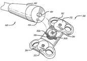
- FIG. 13is a top perspective view of the plate and fastener of FIG. 1 and instrumentation for compressing the plate and instrumentation for locking the fastener in accordance with a preferred embodiment of the present invention.
- FIG. 14is a top plan view of the plate and fastener of FIG. 1 in a compressed state with the instrumentation of FIG. 13 shown in cross section engaging the ends of the plate to compress the plate in the direction of the arrows and with the instrumentation engaging the fastener.
- FIG. 15is a partial cross sectional view along line 15 - 15 of FIG. 14 .
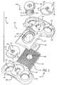
- FIG. 16is a top perspective view of a plate, a fastener, and locking elements in accordance with another preferred embodiment of the present invention.
- FIG. 17is a top plan view of the plate, fastener, and locking elements of FIG. 16 .
- FIG. 18is a top plan view of the plate of FIG. 16 in an elongated state, fastener, and locking elements.
- FIG. 19is a bottom plan view of the plate and fastener of FIG. 16 .
- FIG. 20is a partial cross sectional view along line 20 - 20 of the plate of FIG. 17 .
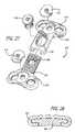
- FIG. 21is an exploded top perspective view of the plate, fastener, and locking elements of FIG. 16 .
- FIG. 22is an exploded bottom perspective view of the plate, fastener, and locking elements of FIG. 16 .
- FIG. 23is a top plan view of the plate, fastener, and locking elements of FIG. 16 and a partial fragmentary perspective view of an instrument for compressing the plate and securing the fastener in accordance with another preferred embodiment of the present invention.
- FIG. 24is an enlarged cross sectional view of the plate of FIG. 16 with the instrument of FIG. 23 engaging the fastener and positioned within the plate.
- FIG. 25is a fragmentary top plan view of the plate of FIG. 16 in an elongated state with the instrument of FIG. 23 shown in cross section engaging the fastener and positioned within the plate.
- FIG. 26is a fragmentary top plan view of the plate of FIG. 16 in a compressed state with the instrument of FIG. 23 shown in cross section engaging the fastener and positioned within the plate to rotate the fastener in the direction of the arrow to compress the plate.
- FIG. 27is an exploded top perspective view of a plate, a fastener, and locking elements in accordance with another preferred embodiment of the present invention.
- FIG. 28is a cross sectional view transverse to the longitudinal axis of the plate of FIG. 27 .
- FIG. 29is a top plan view of a plate, fasteners, and locking elements in accordance with another preferred embodiment of the present invention.
- FIG. 30is an exploded top perspective view of the plate, fasteners, and locking elements of FIG. 29 .
- FIG. 31is an exploded bottom perspective view of the plate, fasteners, and locking elements of FIG. 29 .
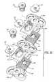
- FIG. 32is a top plan view of the plate, fasteners, and locking elements of FIG. 29 .
- FIG. 33is a bottom plan view of the plate, fasteners, and locking elements of FIG. 29 .
- FIG. 34is a side elevation view of the plate of FIG. 29 .
- FIG. 35is a partial cross sectional view along the longitudinal axis of the plate of FIG. 29 .
- FIG. 36is a top plan view of the plate in an elongated position, fasteners, and locking elements of FIG. 29 .
- FIG. 37is a top perspective view of the plate of FIG. 29 and another preferred embodiment of instrumentation for compressing the plate and instrumentation for locking the fastener in accordance with the present invention.
- FIG. 39is a side elevation view of the plate of FIG. 38 with the instrumentation shown in partial fragmentary, hidden line, and cross sectional views.
- FIG. 40is an exploded top perspective view of a plate, fasteners, and locking elements in accordance with another preferred embodiment of the present invention.
- FIG. 41is a top plan view of a plate, fasteners, and locking elements in accordance with another preferred embodiment of the present invention.
- FIG. 42is a top plan view of a plate, fasteners, and locking elements in accordance with another preferred embodiment of the present invention.
- FIG. 43is an enlarged fragmentary cross sectional view of the plate, locking element, and bone screws of FIG. 42 .
- FIG. 44is an enlarged fragmentary cross sectional view of a plate, locking element, and bone screws in accordance with another embodiment of the present invention.
- FIG. 45is a fragmentary top plan view of another preferred embodiment of a plate and a locking element adapted to lock at least two bone screws and a fastener in accordance with the present invention.
- FIG. 46is a fragmentary top plan view of another preferred embodiment of a plate and a locking element adapted to lock at least two bone screws and a fastener in accordance with the present invention.
- the present inventionis for use in the cervical spine where dynamization is highly desired to prevent distraction pseudoarthrosis and to maintain a compressive load across the fusion interfaces.
- the present inventionin one preferred embodiment is directed to a cervical plate generally having at least two movable segments that are attached to the vertebral bodies to be fused and connected in such a way as to permit dynamization of the vertebral bodies preferably along the longitudinal axis of the plate.
- the movement of the segments relative to one anothermay be accompanied by a reduction in the overall length of the plate.
- FIGS. 1-7show a preferred embodiment of a cervical plate 100 in accordance with the present invention.
- Plate 100is preferably formed of a first segment 102 and a second segment 104 in moveable relationship to one another.
- First and second segments 102 , 104can be of various lengths and/or configurations such that when the segments are assembled preferably overlapping at least in part, plates of various lengths and/or configurations can be formed to cover a range of sizes.
- First and second segments 102 , 104can be of the same or different lengths and can be coupled to each other or to an intermediate segment as shown in FIGS. 29-40 and described below in connection with other preferred embodiments of the present invention.
- the overall length of plate 100 and the spacing of segments 102 , 104can be adjusted by moving segments 102 , 104 relative to one another.
- a non-detachable fastener 106couples together first and second segments 102 , 104 .
- Fastener 106is configured to be non-detachably attached to at least one of first and second segments 102 , 104 to couple together two or more plate segments.
- Fastener 106is non-detachable to prevent non-destructive complete uncoupling of first and second segments 102 , 104 from one another during normal use.
- “non-detachable fastener”is defined as a fastener that once attached is not meant to be removed and then reattached. As shown in FIG.
- fastener 106may be embodied in the form of a rivet having a head 108 , a shaft 112 , and a base 114 .
- base 114may be coupled to second segment 104 so that it is permanently attached, but is still capable of an element of rotation about its longitudinal axis.
- Shaft 112 of fastener 106preferably has a thread 116 .
- fastener 106 ′may be configured to be tightened to only one of first and second plate segments 102 , 104 so as to permit movement of first and second segments 102 , 104 relative to one another when fastener 106 ′ is fully tightened.
- fastener 106 ′may have a shoulder 110 adapted to bear upon second segment 104 as indicated by arrow C. Shoulder 110 is dimensioned so as to create a gap 111 between head 108 ′ and first segment 102 so as to still permit a specific and desired motion of first and second segments 102 , 104 relative to one another when fastener 106 ′ is fully tightened.
- the limited motion of first and second segments 102 , 104 relative to one anotherprovides for dynamization of the spinal segment to be fused in that those vertebral bodies are allowed to move closer together to maintain contact.
- first segment 102preferably has an upper surface 118 , a lower surface 120 , a medial portion 122 , and an end 124 .
- First segment 102preferably includes bone screw receiving holes 126 proximate end 124 .
- Bone screw receiving hole 126is preferably configured to receive a single bone screw or the bone screw receiving holes also may be configured to receive more than one bone screw.
- a bone screw receiving holemay be in the form of a slot sized to receive at least two bone screws.
- At least two of bone screw receiving holes 126may be oriented in plate 100 to overlie the anterior aspect of a single cervical vertebral body adjacent a disc space to be fused, though the invention is not so limited.
- a first pair of bone screw receiving holes 126may be configured to overlie the anterior aspect of a first cervical vertebral body adjacent a disc space to be fused and at least a second pair of bone screw receiving holes 126 may be oriented in plate 100 to overlie the anterior aspect of a second cervical vertebral body adjacent the disc space to be fused.
- Bone screw receiving hole 126may, though need not be, configured to form an interference fit with at least a portion of the trailing end of a properly dimensioned bone screw to be received therein.
- Bone screw receiving holes 126may be configured, for example only, so that at least one of bone screw receiving holes 126 may hold a bone screw in a fixed relationship to the plate or may hold a bone screw in a moveable relationship, such as a variable angular relationship, described below.
- bone screw receiving hole 126may have a reduced dimension proximate lower surface 120 of segment 102 to form a seat 127 .
- Seat 127may have a surface adapted to contact at least a portion of a bone screw inserted therein. The surface may be at least in part planar, at least in part curved, or have any other configuration suitable for contacting at least a portion of a bone screw.
- End 124 of first segment 102may also include a tool engagement area 128 adapted to cooperatively engage instrumentation for holding plate 100 and instrumentation for moving first and second segments relative to one another to induce a desired amount of compressive force across the fusion sites and to permit a desired amount of shortening of plate 100 .
- Medial portion 122preferably has a fastener receiving opening 130 adapted to accommodate fastener 106 to couple first and second segments 102 , 104 to one another.
- Fastener receiving opening 130is preferably configured to permit selected movement of fastener 106 therein and to permit selected motion of first and second segments 102 , 104 along the longitudinal axis of plate 100 .
- Fastener receiving opening 130may include a shoulder 132 recessed from upper surface 118 of first segment 102 adapted to contact the underside of head 108 of fastener 106 in the tightened position to prevent movement of first and second segments 102 , 104 relative to one another.
- fastener 106 ′shoulder 110 contacts second segment 104 and the underside of head 108 ′ is positioned relative to shoulder 132 to permit movement of first and second segments 102 , 104 relative to each other along the longitudinal axis of the plate when in the tightened position providing for dynamization of the vertebral bodies to be fused to occur, if needed.
- Fastener 106 and fastener receiving opening 130cooperate to prevent complete uncoupling of first and second segments 102 , 104 from one another.
- fastener receiving opening 130may be configured to prevent head 108 of fastener 106 from passing therethrough.
- Second segment 104has an upper surface 138 , a lower surface 140 , a medial portion 142 , and an end 144 .
- Second segment 104preferably has bone screw receiving holes 126 proximate end 144 .
- End 144may also include a tool engagement area 146 adapted to cooperatively engage instrumentation for holding plate 100 and instrumentation for moving first and second segments 102 , 104 relative to one another to induce a desired amount of compressive force across the fusion site and to permit a desired amount of shortening of plate 100 .
- Medial portion 142preferably includes a fastener receiving opening 148 for receiving a portion of fastener 106 .
- the first and second plate segmentsmay be modular components of various configurations assembled by the manufacturer of the plate and provided to the surgeon in an assembled state.
- the plateIn the assembled state, the plate has a non-detachable fastener that prevents non-destructive complete uncoupling of the first and second segments during normal use.
- Fastener receiving opening 148preferably has a thread 150 adapted to engage with thread 116 of fastener 106 .
- the threaded engagement of fastener 106 to fastener receiving opening 148permits first segment 102 and second segment 104 to be attached to each other when fastener 106 is sufficiently rotated and tightened.
- first and second segments 102 , 104are secured together and locked and do not move relative to each other.
- fastener 106 ′ shown in FIG. 8is used in the tightened position, first and second segments 102 , 104 are capable of moving relative to each other.
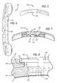
- Lower surfaces 120 , 140 of first and second segments 102 , 104are preferably at least in part concave along at least a portion of the longitudinal axis of the plate, may be bi-concave at least in part, that is, concave along the longitudinal axis of plate 100 and concave transverse to the longitudinal axis of the plate, or may have any shape suitable for the intended purpose transverse to the longitudinal axis of the plate.
- plate 100may be adapted for other curvatures or have no curvature without departing from the intended purpose within the broad scope of the present invention.
- Lower surfaces 120 , 140are preferably adapted to contact at least a portion of the vertebral bodies to be fused and may be configured to conform to the anterior aspect of at least a portion of the vertebral bodies.
- Second segment 104preferably includes a tab 136 extending from medial portion 142 .
- Tab 136is configured to cooperatively engage a tab receiving recess 134 in the lower surface 120 of first segment 102 .
- Tab 136acts as a spring to maintain first and second segments 102 , 104 aligned along the longitudinal axis of plate 100 .
- Tab 136also functions to limit movement of first segment 102 in a direction transverse to longitudinal axis of plate 100 to prevent end 124 from dropping down beyond a desired position. This limited movement of first segment 100 prevents medial portion 122 of first segment 102 from lifting away from medial portion 142 beyond a desired position, so that ratchetings 150 are not overly separated and rendered less effective as described in more detail below.
- segments 102 , 104are possible to hold apart segments 102 , 104 and to limit movement of the segments in a direction transverse to the longitudinal axis of the plate.
- the longitudinal curvatures of first and second segments 102 , 104can be slightly different to spring apart segments 102 , 104 .
- the radius of curvature of the lower surface of segment 102may be different that the radius of curvature of the upper surface of segment 104 .
- lower surface 120 of first segment 102 and upper surface 138 of second segment 104are preferably configured to interdigitate with one another to permit selected adjustment of the length of plate 100 .
- lower surface 120 and upper surface 138may include a surface configuration, such as ratchetings 152 , configured to cooperatively interdigitate to permit selected and sequential movement along the longitudinal axis of plate 100 .
- the ratchetingsare preferably biased to allow movement in one preferred direction along the longitudinal axis of the plate so as to allow shortening of the plate and resist lengthening of the plate.
- FIGS. 9 and 10show an embodiment of ratchetings having a configuration that is useful if no movement of first and second segments 102 , 104 is desired after fastener 106 is tightened.
- a preferred angular relationship of the cross section of ratchetings 152 ais a 45-45-90 degree triangular relationship.
- Ratchetings 152 apermit for the fixed positioning of first and second segments 102 , 104 relative to one another to create a selected length of plate 100 .
- FIG. 9shows that shows that is useful if no movement of first and second segments 102 , 104 is desired after fastener 106 is tightened.
- a preferred angular relationship of the cross section of ratchetings 152 ais a 45-45-90 degree triangular relationship.
- Ratchetings 152 apermit for the fixed positioning of first and second segments 102 , 104 relative to one another to create a selected length of plate 100 .
- FIG. 9shows that in a first position,
- fastener 106is configured to have at least one position that permits movement of the first and second segments along the longitudinal axis of plate 100 as well as along an axis transverse to the longitudinal axis of plate 100 such that ratchetings 152 can move apart.
- Fastener 106can be tightened to a second position to resist or prevent movement of segments 102 , 104 relative to one another. For example, movement of segments 102 , 104 can be resisted in a direction along at least a portion of the longitudinal axis of plate 100 .
- FIGS. 11 and 12show another preferred embodiment of ratchetings 152 b having a forward-facing configuration for permitting movement in a single direction.
- the configuration of ratchetings 152 bis useful when movement of first and second segments 102 , 104 is desired to permit further shortening of the plate.
- a preferred angular relationship of the triangular cross section of ratchetings 152 bis a 30-60-90 degree triangular relationship.
- FIG. 12due to the forward facing angle of ratchetings 152 b, sliding movement of first and second segments 102 , 104 in the direction, as indicated by the arrow, along the longitudinal axis of plate 100 is facilitated by the ramped surface 154 .
- fastener 106 or 106 ′is configured to have at least one position that permits movement of first and second segments 102 , 104 in both directions along the longitudinal axis of plate 100 as well as along an axis transverse to the longitudinal axis of plate 100 such that ratchetings 152 b can move apart.
- fastener 106in a first position fastener 106 can be less than fully tightened to plate 100 as desired by the surgeon to permit movement of first and second segments relative to each other.
- Fastener 106 ′can further have a second position that permits movement of segments 102 , 104 relative to one another only in a single direction along the longitudinal axis of plate 100 and limits movement along an axis transverse to the longitudinal axis of plate 100 .
- plate 100can be shortened if the distance between the two adjacent vertebral bodies decreases, even after plate 100 is installed, so that the vertebral bodies are not held apart by plate 100 , to prevent the occurrence of pseudoarthrosis.
- One of the benefits of a forward-facing configuration of ratchetings 152 bis the ability to store and impart a compressive load across the fusion site. The compressive load stored may be applied by the surgeon and/or compressive loads that occur randomly with neck motion during the healing phase.
- First and second segments 102 , 104may be pre-adjusted to correspond to the appropriate size and spacing of the adjacent vertebral bodies to be fused prior to placement of plate 100 against the vertebral bodies by moving first and second segments 102 , 104 relative to one another while fastener 106 is only partially tightened for the purpose of appropriately adjusting the length of the plate. Then, fastener 106 may be further tightened to secure first and second segments 102 , 104 in the desired position.
- plate 100includes at least one bone screw lock 172 adapted to lock to plate 100 at least two bone screws inserted in bone screw receiving holes 126 .
- Bone screw locks 172are coupled to plate 100 and may be removable or may be non-detachably attached to plate 100 .
- Bone screw locks 172may be coupled to plate 100 prior to the insertion of the bone screws into bone screw receiving holes 126 .
- the bone screw locksmay be coupled to the plate after the insertion of the bone screws into the bone screw receiving holes.
- bone screw lock 172may have a tool engagement portion 174 adapted to cooperatively engage an instrument used for coupling bone screw lock 172 to plate 100 and at least one cutout 176 .
- Each cutout 176is oriented so as to permit introduction of a bone screw into an adjacent bone screw receiving hole when bone screw lock 172 is coupled to plate 100 and in the appropriate orientation. It is appreciated that other configurations of the bone screw lock are possible so as to permit introduction of a bone screw into a bone screw receiving hole adjacent to the bone screw lock without interference from the bone screw lock.
- Plate 100may have an opening 178 for receiving at least a portion of locking element 172 and may, but need not, include a recess 180 for receiving at least a portion of locking element 172 therein.
- Bone screw lock 172may have a stem 182 configured to fit at least in part within opening 178 in plate 100 . Stem 182 and opening 178 may be threaded to threadably engage bone screw lock 172 to plate 100 .
- at least a portion of the interior perimeter of recess 180 and at least a portion of the perimeter of the bone screw lockmay be threaded to threadably engage the bone screw lock to the plate.
- bone screw locks 172are configured to move from an initial position, that permits the insertion of bone screws into the bone screw receiving holes, to a final position that is adapted to extend over at least a portion of at least two of the bone screws to retain the bone screws to the plate.
- the bone screw lockmay be adapted to be rotated from the initial position to the final position, and preferably, less than a full rotation of the bone screw lock rotates the bone screw lock from the initial position to the final position.
- the bone screw lock in the final positioncovers at least a portion of at least two of the bone screw receiving holes.
- the bone screw lockslides from the initial position to the final position.
- the bone screw lockcan slide over at least a portion of at least two of the bone screw receiving holes and/or slide over at least a portion of at least two bone screws in the bone screw receiving holes.
- the plates of the present inventionmay be utilized with any lock suitable for locking a plurality of bone screws to an anterior cervical plate known to those of ordinary skill in the art, including but not limited to, the bone screw locks taught by Michelson in U.S. Pat. No. 6,193,721 (the '721 patent) incorporated by reference herein.
- the surgeonmay induce a desired amount of “preload,” or compressive force across the fusion site after plate attachment by moving first and second segments 102 , 104 toward one another to shorten the length of plate 100 as desired.
- preloadenhances fusion by maintaining a compressive force between adjacent vertebral bodies and reducing the chance that gaps might develop as new living bone replaces the dead bone during the fusion process.
- FIGS. 13-15show a preferred embodiment of instrumentation 200 for compressing and locking plate 100 .
- Instrumentation 200has a handle 202 with a pair of tongs 204 , 206 in moveable relationship to each. Tongs 204 , 206 are configured to cooperatively engage ends 124 , 144 of first and second segments, 102 , 104 , respectively.
- Instrumentation 200may be used to hold and position plate 100 in a desired position at the fusion site during at least a portion of the procedure for installing plate 100 . Any instrument capable of engaging the plate so as to serve the intended purpose would be within the scope of the instrumentation and method of the present invention.
- an instrument 208 having a head 210 configured to cooperatively engage fastener 106is used to tighten fastener 106 to secure first and second segments 102 , 104 in a desired position.
- segments 102 , 104may maintain a compressive load across the disc space if desired.
- Head 210 of instrument 200may have a hex-shaped configuration.
- FIGS. 16-22show another preferred embodiment of a cervical plate 300 having an internal compression mechanism in accordance with the present invention.
- Plate 300is similar to plate 100 except that fastener receiving opening 330 and fastener 306 function as part of a mechanism to move first and second segments 302 , 304 . relative to one another to change the length of plate 300 to generate a compressive load across the disc space between two adjacent vertebral bodies to be fused.
- Fastener receiving opening 330includes instrument pin receiving recesses 362 a and 362 b for cooperating with the pin of an instrument 400 (described below) for moving first and second segments 302 , 304 relative to one another.
- plate 300has pins 358 and tracks 360 to maintain first and second segments 302 , 304 aligned along the longitudinal axis of plate 300 .
- Bone screw lock 372is adapted to lock to plate 300 at least two bone screws inserted in bone screw receiving holes 326 .
- first segment 302preferably has two pins 358 depending therefrom for engagement in corresponding tracks 360 in second segment 304 .
- Pins 358slideably engage tracks 360 , respectively, and travel therein when first and second segments 302 , 304 are moved relative to one another.
- Tracks 360are staggered along the length of medial portion 342 and pins 358 are staggered along the length of medial portion 322 to maintain first and second segments 302 , 304 aligned along the longitudinal axis of plate 300 . It is appreciated that any plate configuration to achieve the intended purpose of maintaining first and second segments 302 , 304 aligned along the longitudinal axis of the plate would be within the scope of the present invention.
- FIGS. 23-26show a preferred embodiment of an instrumentation 400 used for compressing and locking plate 300 .
- Instrumentation 400has a working end 402 configured to cooperatively engage fastener receiving opening 330 and fastener 306 .
- instrument 400can be used to move segments 302 , 304 toward one another to shorten the length of plate 300 , create a compressive load across the disc space, and concurrently tighten fastener 306 (if desired) to secure first and second segments 302 , 304 in a preferred position.
- Working end 402 of instrument 400preferably has a driver portion 404 configured to cooperatively engage driver receiving opening 364 in fastener 306 .
- Driver portion 404is preferably hex-shaped.
- Working end 402preferably has a pin 406 extending therefrom and displaced from driver portion 404 to engage one of pin receiving recesses 362 a and 362 b, respectively, when driver portion 404 is engaged with driver receiving opening 364 in fastener 306 .
- instrument 400rotates fastener 306 in the direction of arrow A as shown in FIG. 26 to move first segment 302 toward second segment 304 in the direction of arrow B to reduce the length of plate 300 and can if desired concurrently tighten fastener 306 .
- the configuration of plate 300provides for an internal compression mechanism that can be operated by a driver instrument eliminating the need for an externally applied compression apparatus for shortening plate 300 and creating a compressive load.
- FIGS. 27-28show another preferred embodiment of a cervical plate 500 in accordance with the present invention.
- Plate 500is similar to plate 100 except that first segment 502 is configured to receive at least a portion of second segment 504 therein in a tongue and groove configuration.
- first segment 502preferably has a C-shaped cross section and second segment 504 preferably has a T-shaped cross section.
- the configurations of segments 502 , 504 in this embodiment of the present inventionkeep segments 502 , 504 aligned along the longitudinal axis of plate 500 and limit movement of segments 502 , 504 in a direction generally transverse to the longitudinal axis of plate 500 .
- Bone screw lock 572is adapted to lock to plate 500 at least two bone screws inserted in bone screw receiving holes 526 .
- FIGS. 29-36show another preferred embodiment of a cervical plate 600 in accordance with the present invention.
- Plate 600is similar to plate 100 except that it is configured for use across two levels of the cervical spine.
- plate 600further includes an intermediate third segment 666 between first and second segments 602 , 604 .
- Third segment 666has a first end 668 configured to cooperatively engage first segment 602 .
- Third segment 666has a second end 670 configured to cooperatively engage second segment 604 .
- Third segment 666 and first and second segments 602 , 604are articulated and can be moved to vary the spacing between the bone screw receiving holes of the plate segments as well as the overall length of the plate.
- Third segment 666can be made of different lengths and/or configurations to vary the distance between first and second segments 602 , 604 to further vary the spacing between the bone screw receiving holes and further vary the overall length of the plate.
- First end 668 of third segment 666has similar features to second segment 604 including a fastener receiving recess 648 , bone screw receiving holes 626 , ratchetings 652 on at least a portion of its upper surface 638 , and a tab 636 .
- Second end 670 of third segment 666has similar features to first segment 602 including a ratchetings 652 on at least a portion of its lower surface 620 and a tab receiving recess 634 .
- a first fastener 606couples together first segment 602 to first end 668 of third segment 666 .
- a second fastenercouples together second segment 604 to second end 670 of third segment 666 .
- Additional segments 666may be added for use across more than two levels of the spine. Segments 666 are configured to be coupled together with first end 668 of one segment 666 to second end 670 of another segment 666 .
- Bone screw lock 672is adapted to lock to plate 600 at least two bone screws inserted in bone screw receiving holes 6
- FIGS. 37-39show a preferred embodiment of instrumentation 700 for compressing and locking plate 600 .
- Instrumentation 700has a handle 702 with a pair of tongs 704 , 706 in moveable relationship to each. Tongs 704 , 706 are configured to cooperatively engage ends 624 , 644 of first and second segments, 602 , 604 , respectively, to shorten the overall length of the plate and to apply a desired compressive load across multiple levels of the spine.
- Instrumentation 700may be used to position plate 600 in a desired position at the fusion site during at least a portion of the procedure for installing plate 600 .
- An instrumentmay be used for holding the plate such as the instrumentation disclosed in the '721 patent incorporated by reference above.
- Instrument 700can be used to move segments 602 , 604 toward one another and toward third segment 666 to shorten the length of plate 600 and create a compressive load across the respective disc spaces.
- instrument 700 ′may be used to move first or second segment 602 , 604 toward third segment 666 so that a compressive load may be applied to one disc space at a time.
- Instrument 700 ′has a tong 704 ′ similar to tong 704 for engaging one of ends 624 , 644 of first and second segments, and forked tong 707 for engaging the third segment as shown in FIG. 38 .
- an instrument 708 having a head 710 configured to cooperatively engage fastener 606is used to tighten fastener 606 to secure first, second, and third segments 602 , 604 , 666 in a desired position.
- FIG. 40shows another preferred embodiment of a cervical plate 800 in accordance with the present invention.
- Plate 800is similar to plate 600 except that first segment 802 is configured to receive at least a portion of the first end 868 of third segment 866 therein in a tongue and groove configuration and second end 870 of third segment 866 is configured to receive at least a portion of second segment 804 therein, in a tongue and groove configuration.
- first segment 802is configured to receive at least a portion of the first end 868 of third segment 866 therein in a tongue and groove configuration
- second end 870 of third segment 866is configured to receive at least a portion of second segment 804 therein, in a tongue and groove configuration.
- Bone screw lock 872is adapted to lock to plate 800 at least two bone screws inserted in bone screw receiving holes 826 .
- the plate of the present inventionpreferably includes at least one bone screw lock adapted to lock to the plate at least two bone screws inserted into the bone screw receiving holes, respectively.
- the plate of the present inventionmay include more than one bone screw lock, each lock being adapted to lock to the plate at least two bone screws inserted into the bone screw receiving holes, respectively.
- FIG. 41shows a cervical plate 900 with locking elements 902 in accordance with another preferred embodiment of the present invention.
- Locking elements 902are adapted to lock at least two bone screws installed in each of bone screw receiving holes 916 , respectively.
- Locking element 902is in moveable relationship to plate 900 so that locking element 902 can be pre-installed to plate 900 prior to the insertion of bone screws into bone screw receiving holes 916 .
- locking element 902can be slid to one side of the plate as shown in the top portion of the plate in FIG. 41 to allow for insertion of a first bone screw into a first bone screw receiving hole 916 on the opposite side of plate 900 .
- Locking element 902is then moved to the opposite side of plate 900 to permit insertion of a second bone screw into the second bone screw receiving hole 916 ; Locking element is then moved to cover at least a portion of both first and second bone screws and can be locked in place by a screw 917 as shown in the middle and bottom portions of plate 900 in FIG. 41 .
- FIGS. 42 and 43show a cervical plate 1000 with locking elements 1002 in accordance with another preferred embodiment of the present invention.
- Locking elements 1002are installed to cover at least a portion of two bone screw receiving holes 1016 .
- the bone screwsare installed in bone screw receiving holes 1016 and locking element 1002 is placed over at least a portion of two bone screws to lock the bone screws.
- Locking element 1002can be held in place with a screw 1017 that passes at least in part through opening 1003 in locking element 1002 and engages opening 1005 in plate 1000 to lock two bone screws 1048 to plate 1000 as shown in FIG. 43 .
- Bone screws 1048preferably have a leading end configured for insertion into the cervical spine and a head 1049 opposite the leading end that may be configured to contact locking element 1002 .
- bone screws 1048may be configured to be in a fixed relationship to plate 1000 such as shown in FIG. 43 .
- FIG. 44is a fragmentary cross sectional view of another preferred embodiment of a locking element 1002 ′ and bone screws 1048 ′.
- Locking element 1002 ′has a bottom surface adapted to cooperate with a rounded portion of head 1049 ′ of bone screws 1048 ′ and is adapted to hold bone screws 1048 ′ in an angular relationship to plate 1000 ′. Examples of preferred fixed-angled locking elements are taught by Michelson in U.S. Pat. No. 6,139,550 (the '550 patent) entitled “Skeletal Plating System,” the disclosure of which is hereby incorporated by reference herein. Locking element 1002 ′ may also permit movement of bone screw 1048 ′ relative to plate 1000 ′.
- Locking element 1002 ′may also be adapted to adjustably lock bone screws 1048 ′ in a variable angle relationship relative to plate 1000 ′.
- Examples of preferred variable-angled locking elementsare taught by Michelson in the '550 patent.
- the rounded portion of head 1049 ′permits bone screws 1048 ′ to be in a moveable relationship, such as for example in a variable angular relationship to plate 1000 ′.
- Other configurationsare possible for the intended purpose and are within the broad scope of the present invention.
- FIG. 45shows a plate 1100 and a locking element 1180 adapted to lock at least two bone screws and a fastener 1134 in accordance with the present invention.
- locking element 1180is configured to be preinstalled to plate 1100 prior to insertion of the bone screws in bone screw receiving holes 1116 and attachment of fastener 1134 to plate 1100 .
- Locking element 1180has a first position that permits insertion of bone screws in respective bone screw receiving holes 1116 and installation and/or movement of fastener 1134 .
- Locking element 1180has a second position that covers at least a portion of at least two bone screw receiving holes 1116 and fastener 1134 to lock at least two bone screws and fastener 1134 to plate 1100 .
- Locking element 1180may preferably be configured to rotatably and/or slideably cover at least a portion of two bone screws in bone screw receiving holes 1116 and at least a portion of fastener 1134 .
- FIG. 46shows another preferred embodiment of a plate 1200 and locking element 1280 adapted to lock at least two bone screws and a fastener 1234 in accordance with the present invention.
- Locking element 1280is configured to be installed to plate 1200 after insertion of bone screws in bone screw receiving holes 1216 and attachment of fastener 1234 to plate 1200 .
- Locking element 1280is configured to cover at least a portion of at least two bone screw receiving holes 1216 and fastener 1234 to lock at least two bone screws and at least a portion of fastener 1234 to plate 1200 .
- Locking element 1280is preferably attached to plate 1200 by a screw 1217 or by any other means suitable for the intended purpose.
- the plates of present inventionmay include a bone screw system that allows the vertebrae to move toward an interposed bone graft, and each other if necessary, instead of keeping the vertebrae apart during the occurrence of the resorption phase of the creeping substitution process.
- a bone screw systemthat allows the vertebrae to move toward an interposed bone graft, and each other if necessary, instead of keeping the vertebrae apart during the occurrence of the resorption phase of the creeping substitution process.
- the '550 patentdiscloses three types of screw-plate-lock systems, which are themselves combinable with one another, as follows: (1) Passive Dynamic; (2) Self-Compressing; and (3) Active Dynamic and are incorporated by reference herein.
- the plate of the present inventionrequires (1) at least one fastener non-detachably attached to the plate to prevent complete uncoupling of the plate segments from one another; and (2) at least one lock that is adapted to lock at least two bone screws so as to prevent the screws from backing out from the bone screw receiving holes of the plate. Plates similar to that of the present invention described herein having detachable fasteners wherein the plates are adapted to be assembled and reassembled are being pursued in related applications. Plates similar to that of the present invention described herein having single-lock mechanisms adapted to lock only one bone screw as described in the '550 patent and the '721 patent are being pursued in related applications.
- any of the embodiments of the plates described hereincan be combined with, comprised of, or used with fusion promoting substances and/or bone promoting materials, including genes coding for the production of bone, bone morphogenetic protein, substances other than bone, and bone.
- the plates, screws, fasteners, and/or screw locksmay also be combined with material and/or a substance for inhibiting scar formation.
- the plates, screws, fasteners, and/or screw locksmay be combined with an antimicrobial material and/or surface treated or coated to be antibacterial and/or antimicrobial, such as for example, by a silver coating.
- At least a portion of the bottom surface of the platescan preferably have a porous, and/or textured and/or roughened surface and may be coated with, impregnated with, or comprise of fusion promoting substances (such as bone morphogenetic proteins) so as to encourage the growth of bone along the underside of the plate from bone portion to bone portion.
- the textured bottom surfacealso provides a medium for retaining fusion promoting substances with which the bottom surface layer can be impregnated prior to installation.
- the bottom surface of the platemay be given the desired porous textured form by rough blasting or any other conventional technology, such as etching, plasma spraying, sintering, and casting for example.
- the bottom surfaceis formed to have a porosity or pore size in the order of 50-500 microns, and preferably 100-300 microns.
- Bone growth promoting substances with which the porous, textured bottom surface can be impregnatedinclude, but are not limited to, bone morphogenetic proteins, hydroxyapatite, or hydroxyapatite tricalcium phosphate.
- the plate, screws, fasteners, and/or bone screw locksmay include at least in part a resorbable and/or bioresorbable material which can further be impregnated with a bone growth material so that as the resorbable and/or bioresorbable material is resorbed by the body of the patient, the bone growth material is released, thus acting as a time release mechanism.
- the bioresorbable materialmay be, for example, at least in part bone.
- the plate of the present inventionmay be used in combination with a spinal fixation implant such as any object, regardless of material, that can be inserted into any portion of the spine, such as but not limited to interbody spinal implants, interbody spinal fusion implants, structural bone grafts, mesh, cages, spacers, staples, bone screws, plates, rods, tethers of synthetic cords or wires, or other spinal fixation hardware.
- the interbody spinal fusion implantsmay be at least in part bone, for example only, an allograft interbody bone graft.
- the spinal interbody spinal fusion implantmay be at least in part artificial.
- At least one of the plate, screws, fasteners, and/or bone screw locksmay be, if so desired, electrified for purposes of stimulating bone growth and contributing to bone fusion.
Landscapes
- Health & Medical Sciences (AREA)
- Orthopedic Medicine & Surgery (AREA)
- Life Sciences & Earth Sciences (AREA)
- Surgery (AREA)
- Neurology (AREA)
- Heart & Thoracic Surgery (AREA)
- Engineering & Computer Science (AREA)
- Biomedical Technology (AREA)
- Nuclear Medicine, Radiotherapy & Molecular Imaging (AREA)
- Medical Informatics (AREA)
- Molecular Biology (AREA)
- Animal Behavior & Ethology (AREA)
- General Health & Medical Sciences (AREA)
- Public Health (AREA)
- Veterinary Medicine (AREA)
- Prostheses (AREA)
- Surgical Instruments (AREA)
Abstract
Description
Claims (61)
Priority Applications (1)
| Application Number | Priority Date | Filing Date | Title |
|---|---|---|---|
| US11/128,556US7704250B2 (en) | 2001-06-06 | 2005-05-14 | Instrumentation for use with dynamic multilock anterior cervical plate system having non-detachably fastened and moveable segments |
Applications Claiming Priority (4)
| Application Number | Priority Date | Filing Date | Title |
|---|---|---|---|
| US29668101P | 2001-06-06 | 2001-06-06 | |
| US37958902P | 2002-05-09 | 2002-05-09 | |
| US10/160,407US7044952B2 (en) | 2001-06-06 | 2002-06-04 | Dynamic multilock anterior cervical plate system having non-detachably fastened and moveable segments |
| US11/128,556US7704250B2 (en) | 2001-06-06 | 2005-05-14 | Instrumentation for use with dynamic multilock anterior cervical plate system having non-detachably fastened and moveable segments |
Related Parent Applications (1)
| Application Number | Title | Priority Date | Filing Date |
|---|---|---|---|
| US10/160,407DivisionUS7044952B2 (en) | 2001-06-06 | 2002-06-04 | Dynamic multilock anterior cervical plate system having non-detachably fastened and moveable segments |
Publications (2)
| Publication Number | Publication Date |
|---|---|
| US20050216009A1 US20050216009A1 (en) | 2005-09-29 |
| US7704250B2true US7704250B2 (en) | 2010-04-27 |
Family
ID=27388448
Family Applications (3)
| Application Number | Title | Priority Date | Filing Date |
|---|---|---|---|
| US10/160,407Expired - Fee RelatedUS7044952B2 (en) | 2001-06-06 | 2002-06-04 | Dynamic multilock anterior cervical plate system having non-detachably fastened and moveable segments |
| US11/102,112Expired - Fee RelatedUS7621943B2 (en) | 2001-06-06 | 2005-04-09 | Method for installing dynamic multilock anterior cervical plate system having detachably fastened and moveable segments |
| US11/128,556Expired - Fee RelatedUS7704250B2 (en) | 2001-06-06 | 2005-05-14 | Instrumentation for use with dynamic multilock anterior cervical plate system having non-detachably fastened and moveable segments |
Family Applications Before (2)
| Application Number | Title | Priority Date | Filing Date |
|---|---|---|---|
| US10/160,407Expired - Fee RelatedUS7044952B2 (en) | 2001-06-06 | 2002-06-04 | Dynamic multilock anterior cervical plate system having non-detachably fastened and moveable segments |
| US11/102,112Expired - Fee RelatedUS7621943B2 (en) | 2001-06-06 | 2005-04-09 | Method for installing dynamic multilock anterior cervical plate system having detachably fastened and moveable segments |
Country Status (1)
| Country | Link |
|---|---|
| US (3) | US7044952B2 (en) |
Cited By (17)
| Publication number | Priority date | Publication date | Assignee | Title |
|---|---|---|---|---|
| US20050059971A1 (en)* | 1997-02-11 | 2005-03-17 | Michelson Gary K. | Plating system having retaining member that permits movement of at least one bone fastener |
| US20050187552A1 (en)* | 1997-02-11 | 2005-08-25 | Michelson Gary K. | Multilock anterior cervical plating system |
| US20060085001A1 (en)* | 2001-06-04 | 2006-04-20 | Michelson Gary K | Plate system having bone portion engaging anchors and connecting plate |
| US20090259226A1 (en)* | 2001-06-04 | 2009-10-15 | Michelson Gary K | Method for installation of dynamic, single-lock anterior cervical plate system having non-detachably fastened and moveable segments |
| US20110054528A1 (en)* | 2001-06-04 | 2011-03-03 | Michelson Gary K | Dynamic plate system having moveable segments |
| US20110190892A1 (en)* | 2010-02-01 | 2011-08-04 | X-Spine Systems, Inc. | Spinal implant co-insertion system and method |
| US8377139B2 (en) | 2010-06-17 | 2013-02-19 | Aesculap Implant Systems, Llc | Standalone interbody fusion device with locking and release mechanism |
| US8808333B2 (en) | 2009-07-06 | 2014-08-19 | Zimmer Gmbh | Periprosthetic bone plates |
| US8814912B2 (en) | 2012-07-27 | 2014-08-26 | Zimmer Spine, Inc. | Bone stabilization member with bone screw retention mechanism |
| US8828082B2 (en) | 2009-07-09 | 2014-09-09 | R Tree Innovations, Llc | Inter-body implant |
| US9186189B2 (en) | 2000-06-26 | 2015-11-17 | Stryker Spine | Bone screw retaining system |
| US9433454B2 (en) | 2013-03-14 | 2016-09-06 | Amei Technologies, Inc. | Variable angle screws, plates and systems |
| US9445851B2 (en) | 2009-07-24 | 2016-09-20 | Spinal Usa, Inc. | Bone plate screw-blocking systems and methods |
| US9468479B2 (en) | 2013-09-06 | 2016-10-18 | Cardinal Health 247, Inc. | Bone plate |
| US9504584B1 (en) | 2011-01-28 | 2016-11-29 | Nuvasive, Inc. | Spinal fusion implant and related methods |
| US10327910B2 (en) | 2013-03-14 | 2019-06-25 | X-Spine Systems, Inc. | Spinal implant and assembly |
| US11123117B1 (en)* | 2011-11-01 | 2021-09-21 | Nuvasive, Inc. | Surgical fixation system and related methods |
Families Citing this family (199)
| Publication number | Priority date | Publication date | Assignee | Title |
|---|---|---|---|---|
| US7306628B2 (en) | 2002-10-29 | 2007-12-11 | St. Francis Medical Technologies | Interspinous process apparatus and method with a selectably expandable spacer |
| US7201751B2 (en) | 1997-01-02 | 2007-04-10 | St. Francis Medical Technologies, Inc. | Supplemental spine fixation device |
| US6068630A (en)* | 1997-01-02 | 2000-05-30 | St. Francis Medical Technologies, Inc. | Spine distraction implant |
| US7959652B2 (en) | 2005-04-18 | 2011-06-14 | Kyphon Sarl | Interspinous process implant having deployable wings and method of implantation |
| US6666867B2 (en)* | 2001-02-15 | 2003-12-23 | Fast Enetix, Llc | Longitudinal plate assembly having an adjustable length |
| US7537604B2 (en)* | 2002-11-19 | 2009-05-26 | Acumed Llc | Bone plates with slots |
| US7186256B2 (en) | 2001-06-04 | 2007-03-06 | Warsaw Orthopedic, Inc. | Dynamic, modular, single-lock anterior cervical plate system having assembleable and movable segments |
| US7041105B2 (en) | 2001-06-06 | 2006-05-09 | Sdgi Holdings, Inc. | Dynamic, modular, multilock anterior cervical plate system having detachably fastened assembleable and moveable segments |
| US7044952B2 (en)* | 2001-06-06 | 2006-05-16 | Sdgi Holdings, Inc. | Dynamic multilock anterior cervical plate system having non-detachably fastened and moveable segments |
| US6755833B1 (en) | 2001-12-14 | 2004-06-29 | Kamaljit S. Paul | Bone support assembly |
| US7070599B2 (en) | 2002-07-24 | 2006-07-04 | Paul Kamaljit S | Bone support assembly |
| US6932820B2 (en) | 2002-01-08 | 2005-08-23 | Said G. Osman | Uni-directional dynamic spinal fixation device |
| US9101422B2 (en)* | 2002-02-01 | 2015-08-11 | Zimmer Spine, Inc. | Spinal plate system for stabilizing a portion of a spine |
| US20040019353A1 (en)* | 2002-02-01 | 2004-01-29 | Freid James M. | Spinal plate system for stabilizing a portion of a spine |
| US7077843B2 (en) | 2002-06-24 | 2006-07-18 | Lanx, Llc | Cervical plate |
| US7175623B2 (en) | 2002-06-24 | 2007-02-13 | Lanx, Llc | Cervical plate with backout protection |
| US8506605B2 (en)* | 2002-09-18 | 2013-08-13 | Simplicity Orthopedics, Inc. | Method and apparatus for securing an object to bone and/or for stabilizing bone |
| US7931674B2 (en) | 2005-03-21 | 2011-04-26 | Kyphon Sarl | Interspinous process implant having deployable wing and method of implantation |
| US8070778B2 (en) | 2003-05-22 | 2011-12-06 | Kyphon Sarl | Interspinous process implant with slide-in distraction piece and method of implantation |
| US7909853B2 (en) | 2004-09-23 | 2011-03-22 | Kyphon Sarl | Interspinous process implant including a binder and method of implantation |
| US7549999B2 (en)* | 2003-05-22 | 2009-06-23 | Kyphon Sarl | Interspinous process distraction implant and method of implantation |
| US8048117B2 (en) | 2003-05-22 | 2011-11-01 | Kyphon Sarl | Interspinous process implant and method of implantation |
| US7833246B2 (en) | 2002-10-29 | 2010-11-16 | Kyphon SÀRL | Interspinous process and sacrum implant and method |
| US7175624B2 (en)* | 2002-12-31 | 2007-02-13 | Depuy Spine, Inc. | Bone plate and screw system allowing bi-directional assembly |
| US7048739B2 (en)* | 2002-12-31 | 2006-05-23 | Depuy Spine, Inc. | Bone plate and resilient screw system allowing bi-directional assembly |
| US7914561B2 (en) | 2002-12-31 | 2011-03-29 | Depuy Spine, Inc. | Resilient bone plate and screw system allowing bi-directional assembly |
| US7341591B2 (en)* | 2003-01-30 | 2008-03-11 | Depuy Spine, Inc. | Anterior buttress staple |
| US8172885B2 (en)* | 2003-02-05 | 2012-05-08 | Pioneer Surgical Technology, Inc. | Bone plate system |
| US7722653B2 (en)* | 2003-03-26 | 2010-05-25 | Greatbatch Medical S.A. | Locking bone plate |
| US7905883B2 (en)* | 2003-03-26 | 2011-03-15 | Greatbatch Medical S.A. | Locking triple pelvic osteotomy plate and method of use |
| BRPI0408769A (en)* | 2003-03-26 | 2006-03-28 | Swiss Orthopedic Solutions Sa | lock bone plate |
| US7776047B2 (en)* | 2003-04-09 | 2010-08-17 | Depuy Spine, Inc. | Guide for spinal tools, implants, and devices |
| US7935123B2 (en) | 2003-04-09 | 2011-05-03 | Depuy Acromed, Inc. | Drill guide with alignment feature |
| US7909829B2 (en) | 2003-06-27 | 2011-03-22 | Depuy Spine, Inc. | Tissue retractor and drill guide |
| US20040204712A1 (en)* | 2003-04-09 | 2004-10-14 | Eric Kolb | Bone fixation plates |
| US7416553B2 (en)* | 2003-04-09 | 2008-08-26 | Depuy Acromed, Inc. | Drill guide and plate inserter |
| US20090254124A1 (en)* | 2003-05-08 | 2009-10-08 | Bickley Barry T | Method and apparatus for securing an object to bone and/or for stabilizing bone |
| US7909848B2 (en) | 2003-06-27 | 2011-03-22 | Depuy Spine, Inc. | Tissue retractor and guide device |
| KR100552117B1 (en)* | 2003-07-22 | 2006-02-13 | 유앤아이 주식회사 | Cervical vertebrae device and driver used in it |
| US20050049595A1 (en)* | 2003-09-03 | 2005-03-03 | Suh Sean S. | Track-plate carriage system |
| US7909860B2 (en)* | 2003-09-03 | 2011-03-22 | Synthes Usa, Llc | Bone plate with captive clips |
| US7857839B2 (en) | 2003-09-03 | 2010-12-28 | Synthes Usa, Llc | Bone plate with captive clips |
| US20050059970A1 (en)* | 2003-09-17 | 2005-03-17 | Eric Kolb | Bone fixation systems |
| US8062367B2 (en) | 2003-09-30 | 2011-11-22 | X-Spine Systems, Inc. | Screw locking mechanism and method |
| US9078706B2 (en) | 2003-09-30 | 2015-07-14 | X-Spine Systems, Inc. | Intervertebral fusion device utilizing multiple mobile uniaxial and bidirectional screw interface plates |
| US8821553B2 (en) | 2003-09-30 | 2014-09-02 | X-Spine Systems, Inc. | Spinal fusion system utilizing an implant plate having at least one integral lock |
| US8372152B2 (en) | 2003-09-30 | 2013-02-12 | X-Spine Systems, Inc. | Spinal fusion system utilizing an implant plate having at least one integral lock and ratchet lock |
| US7641701B2 (en)* | 2003-09-30 | 2010-01-05 | X-Spine Systems, Inc. | Spinal fusion system and method for fusing spinal bones |
| US7182782B2 (en) | 2003-09-30 | 2007-02-27 | X-Spine Systems, Inc. | Spinal fusion system and method for fusing spinal bones |
| US7306605B2 (en) | 2003-10-02 | 2007-12-11 | Zimmer Spine, Inc. | Anterior cervical plate |
| US8182518B2 (en)* | 2003-12-22 | 2012-05-22 | Life Spine, Inc. | Static and dynamic cervical plates and cervical plate constructs |
| EP1708629A4 (en)* | 2004-01-08 | 2011-08-17 | David Mark Allison | Bone fixing device |
| US7678137B2 (en)* | 2004-01-13 | 2010-03-16 | Life Spine, Inc. | Pedicle screw constructs for spine fixation systems |
| US20050177160A1 (en)* | 2004-02-10 | 2005-08-11 | Baynham Bret O. | Dynamic cervical plate |
| US7815666B2 (en)* | 2004-02-10 | 2010-10-19 | Atlas Spine, Inc. | Dynamic cervical plate |
| US8002809B2 (en)* | 2004-02-10 | 2011-08-23 | Atlas Spine, Inc. | Dynamic cervical plate |
| US8328854B2 (en)* | 2004-02-10 | 2012-12-11 | Atlas Spine, Inc. | Cervical plate ratchet pedicle screws |
| US8900277B2 (en) | 2004-02-26 | 2014-12-02 | Pioneer Surgical Technology, Inc. | Bone plate system |
| US7740649B2 (en) | 2004-02-26 | 2010-06-22 | Pioneer Surgical Technology, Inc. | Bone plate system and methods |
| WO2006091827A2 (en)* | 2005-02-25 | 2006-08-31 | Regents Of The University Of California | Device and template for canine humeral slide osteotomy |
| US7524324B2 (en)* | 2004-04-28 | 2009-04-28 | Kyphon Sarl | System and method for an interspinous process implant as a supplement to a spine stabilization implant |
| TW200538092A (en)* | 2004-05-20 | 2005-12-01 | A Spine Holding Group Corp | Sliding cover pull-out prevention bone fixing device |
| US20060036258A1 (en)* | 2004-06-08 | 2006-02-16 | St. Francis Medical Technologies, Inc. | Sizing distractor and method for implanting an interspinous implant between adjacent spinous processes |
| US7744635B2 (en)* | 2004-06-09 | 2010-06-29 | Spinal Generations, Llc | Spinal fixation system |
| US7938848B2 (en)* | 2004-06-09 | 2011-05-10 | Life Spine, Inc. | Spinal fixation system |
| US7727266B2 (en) | 2004-06-17 | 2010-06-01 | Warsaw Orthopedic, Inc. | Method and apparatus for retaining screws in a plate |
| US8753348B2 (en) | 2004-07-02 | 2014-06-17 | DePuy Synthes Products, LLC | Compressor-distractor |
| US8012209B2 (en) | 2004-09-23 | 2011-09-06 | Kyphon Sarl | Interspinous process implant including a binder, binder aligner and method of implantation |
| US9615866B1 (en) | 2004-10-18 | 2017-04-11 | Nuvasive, Inc. | Surgical fixation system and related methods |
| US8062296B2 (en)* | 2005-03-17 | 2011-11-22 | Depuy Products, Inc. | Modular fracture fixation plate system with multiple metaphyseal and diaphyseal plates |
| US8394130B2 (en) | 2005-03-17 | 2013-03-12 | Biomet C.V. | Modular fracture fixation system |
| US20060106387A1 (en)* | 2004-11-16 | 2006-05-18 | Depuy Spine, Inc. | Spinal plate system and method of use |
| US7635364B2 (en)* | 2004-12-01 | 2009-12-22 | Synthes Usa, Llc | Unidirectional translation system for bone fixation |
| US7776090B2 (en) | 2004-12-13 | 2010-08-17 | Warsaw Orthopedic, Inc. | Inter-cervical facet implant and method |
| US7763050B2 (en) | 2004-12-13 | 2010-07-27 | Warsaw Orthopedic, Inc. | Inter-cervical facet implant with locking screw and method |
| US8029540B2 (en) | 2005-05-10 | 2011-10-04 | Kyphon Sarl | Inter-cervical facet implant with implantation tool |
| US7736380B2 (en) | 2004-12-21 | 2010-06-15 | Rhausler, Inc. | Cervical plate system |
| US7322984B2 (en)* | 2005-01-06 | 2008-01-29 | Spinal, Llc | Spinal plate with internal screw locks |
| US8118847B2 (en)* | 2005-03-08 | 2012-02-21 | K2M, Inc. | Anterior vertebral plate with underside locking mechanism |
| US7479143B2 (en)* | 2005-03-11 | 2009-01-20 | Synthes (U.S.A.) | Unidirectional fixation device |
| US20060235403A1 (en) | 2005-03-17 | 2006-10-19 | Jason Blain | Flanged interbody fusion device with locking plate |
| US7993380B2 (en)* | 2005-03-31 | 2011-08-09 | Alphatel Spine, Inc. | Active compression orthopedic plate system and method for using the same |
| WO2006124273A2 (en)* | 2005-05-12 | 2006-11-23 | Stern Joseph D | Revisable anterior cervical plating system |
| US8070749B2 (en) | 2005-05-12 | 2011-12-06 | Stern Joseph D | Revisable anterior cervical plating system |
| US8057521B2 (en)* | 2005-06-03 | 2011-11-15 | Southern Spine, Llc | Surgical stabilization system |
| US20060293668A1 (en)* | 2005-06-10 | 2006-12-28 | Sdgi Holdings, Inc. | Bone screw locking mechanism and method of use |
| US20070055250A1 (en)* | 2005-07-11 | 2007-03-08 | Kamran Aflatoon | Cervical plates with spacer mechanism |
| KR101246113B1 (en)* | 2005-10-25 | 2013-03-20 | 앤썸 오르소패딕스, 엘엘씨 | Bone fastening assembly and bushing and screw for use therewith |
| US7740593B2 (en) | 2005-12-09 | 2010-06-22 | Senorx, Inc | Guide block for biopsy or surgical devices |
| US8100952B2 (en)* | 2005-12-22 | 2012-01-24 | Anthem Orthopaedics Llc | Drug delivering bone plate and method and targeting device for use therewith |
| EP1971282A2 (en) | 2006-01-10 | 2008-09-24 | Life Spine, Inc. | Pedicle screw constructs and spinal rod attachment assemblies |
| US7695473B2 (en)* | 2006-01-18 | 2010-04-13 | Biodynamics Llc | Adjustable bone plate |
| WO2007098188A2 (en)* | 2006-02-21 | 2007-08-30 | Life Spine, Inc. | Structure for joining and retaining multi-part orthopedic implants |
| US7641675B2 (en)* | 2006-03-08 | 2010-01-05 | Warsaw Orthopedic, Inc. | Flexible bone plates and methods for dynamic spinal stabilization |
| US20070233108A1 (en)* | 2006-03-15 | 2007-10-04 | Stalcup Gregory C | Spine fixation device |
| US7867261B2 (en)* | 2006-03-17 | 2011-01-11 | Depuy Products, Inc. | Bone plate with variable torsional stiffness at fixed angle holes |
| US8328853B2 (en)* | 2006-04-03 | 2012-12-11 | Ib Medical, Llc | Static compression device |
| GB2437492B (en)* | 2006-04-29 | 2009-06-24 | Dr Ahmad Fahmi Juanroyee | Multifragment plating system (MFPS) |
| US20080033438A1 (en)* | 2006-08-04 | 2008-02-07 | Roy Frizzell | Cervical Saddle Plate |
| US7674279B2 (en)* | 2006-10-13 | 2010-03-09 | Spinal U.S.A. | Bone plate |
| US8206390B2 (en)* | 2006-11-02 | 2012-06-26 | Warsaw Orthopedic, Inc. | Uni-directional ratcheting bone plate assembly |
| US8147527B2 (en) | 2006-11-28 | 2012-04-03 | Zimmer Spine, Inc. | Adjustable occipital plate |
| US8062366B2 (en)* | 2007-01-08 | 2011-11-22 | Warsaw Orthopedic, Inc. | Ratcheting expandable corpectomy/vertebrectomy cage |
| US8034081B2 (en) | 2007-02-06 | 2011-10-11 | CollabComl, LLC | Interspinous dynamic stabilization implant and method of implanting |
| US20080312699A1 (en)* | 2007-04-11 | 2008-12-18 | Jeffrey Johnson | Recessed plate system |
| US8882813B2 (en)* | 2007-10-19 | 2014-11-11 | Spinesmith Partners, L.P. | Locking mechanisms and associated methods |
| US9072548B2 (en)* | 2007-06-07 | 2015-07-07 | Anthem Orthopaedics Llc | Spine repair assembly |
| US8361126B2 (en)* | 2007-07-03 | 2013-01-29 | Pioneer Surgical Technology, Inc. | Bone plate system |
| US8623019B2 (en) | 2007-07-03 | 2014-01-07 | Pioneer Surgical Technology, Inc. | Bone plate system |
| US8668725B2 (en) | 2007-07-13 | 2014-03-11 | Southern Spine, Llc | Bone screw |
| US7963982B2 (en)* | 2007-07-16 | 2011-06-21 | X-Spine Systems, Inc. | Implant plate screw locking system and screw having a locking member |
| US20090024171A1 (en)* | 2007-07-19 | 2009-01-22 | Vincent Leone | Anatomical Anterior Vertebral Plating System |
| USD592946S1 (en) | 2007-07-25 | 2009-05-26 | Spinal U.S.A. | Locking rivet head |
| EP2208481B1 (en) | 2007-07-27 | 2016-12-28 | R Tree Innovations, LLC | Inter-Body Implantation System |
| US20090177239A1 (en)* | 2007-08-06 | 2009-07-09 | Michael Castro | Cervical plate instrument kit |
| US7867263B2 (en)* | 2007-08-07 | 2011-01-11 | Transcorp, Inc. | Implantable bone plate system and related method for spinal repair |
| US8709054B2 (en) | 2007-08-07 | 2014-04-29 | Transcorp, Inc. | Implantable vertebral frame systems and related methods for spinal repair |
| US8343194B2 (en) | 2007-08-20 | 2013-01-01 | Kamran Aflatoon | Anterior cervical staple |
| US8894651B2 (en)* | 2007-09-11 | 2014-11-25 | Kamran Aflatoon | Method of lateral facet approach, decompression and fusion using screws and staples as well as arthroplasty |
| WO2009036367A1 (en)* | 2007-09-13 | 2009-03-19 | Transcorp, Inc. | Transcorporeal spinal decompression and repair system and related method |
| WO2009036360A1 (en)* | 2007-09-13 | 2009-03-19 | Transcorp, Inc. | Device and method for tissue retraction in spinal surgery |
| US8388663B2 (en) | 2007-09-13 | 2013-03-05 | Stryker Spine | Dynamic cervical plate |
| US8430882B2 (en) | 2007-09-13 | 2013-04-30 | Transcorp, Inc. | Transcorporeal spinal decompression and repair systems and related methods |
| US9247973B2 (en) | 2007-09-28 | 2016-02-02 | DePuy Synthes Products, Inc. | Anti-microbial implant |
| US20090088604A1 (en)* | 2007-09-28 | 2009-04-02 | David Lowry | Vertebrally-mounted tissue retractor and method for use in spinal surgery |
| US8496693B2 (en)* | 2007-10-16 | 2013-07-30 | Amendia Inc. | Bone screw retaining and removal system |
| EP2224868B1 (en)* | 2007-11-21 | 2014-07-30 | Globus Medical, Inc. | Cervical spine stabilization system with extendable plates |
| EP2227181A1 (en) | 2007-11-27 | 2010-09-15 | Transcorp, Inc. | Methods and systems for repairing an intervertebral disc using a transcorporal approach |
| US20090177237A1 (en)* | 2008-01-04 | 2009-07-09 | Spartek Medical, Inc. | Cervical spine implant system and method |
| US20090210008A1 (en)* | 2008-02-20 | 2009-08-20 | Life Spine, Inc. | Modular spine plate with projection and socket interface |
| US8551144B2 (en)* | 2008-04-22 | 2013-10-08 | Collab Comlo, LLC | Bone plate system configurable as static or dynamic implant |
| WO2009132302A1 (en) | 2008-04-25 | 2009-10-29 | Pioneer Surgical Technology, Inc. | Bone plate system |
| US8500783B2 (en)* | 2008-04-30 | 2013-08-06 | Atlas Spine, Inc. | Dynamic cervical plate with spacer |
| US8425514B2 (en)* | 2008-06-25 | 2013-04-23 | Westmark Medical, Llc. | Spinal fixation device |
| WO2010016949A1 (en)* | 2008-08-08 | 2010-02-11 | Alphatec Spine, Inc. | Spinous process device and method of use |
| WO2010025405A1 (en)* | 2008-08-29 | 2010-03-04 | Life Spine, Inc. | Single-sided dynamic spine plates |
| US8623062B2 (en)* | 2008-09-29 | 2014-01-07 | Dimitriy G. Kondrashov | System and method to stablize a spinal column including a spinolaminar locking plate |
| WO2010096773A1 (en)* | 2009-02-20 | 2010-08-26 | Spartan Cage Holding, Llc | Interbody fusion system with intervertebral implant retention assembly |
| US8486115B2 (en)* | 2009-03-13 | 2013-07-16 | Lanx, Inc. | Spinal plate assemblies with backout protection cap and methods |
| US9220547B2 (en) | 2009-03-27 | 2015-12-29 | Spinal Elements, Inc. | Flanged interbody fusion device |
| US8211154B2 (en)* | 2009-04-06 | 2012-07-03 | Lanx, Inc. | Bone plate assemblies with backout protection and visual indicator |
| US9011503B2 (en)* | 2009-07-14 | 2015-04-21 | Neil Duggal | Joint arthrodesis and arthroplasty |
| US9095444B2 (en) | 2009-07-24 | 2015-08-04 | Warsaw Orthopedic, Inc. | Implant with an interference fit fastener |
| KR20120082397A (en)* | 2009-07-24 | 2012-07-23 | 스파이널 유에스에이 엘엘씨 | Bone plate system and methods of using the same |
| USD734853S1 (en) | 2009-10-14 | 2015-07-21 | Nuvasive, Inc. | Bone plate |
| US20110106157A1 (en)* | 2009-10-30 | 2011-05-05 | Warsaw Orthropedic, Inc. | Self-Locking Interference Bone Screw for use with Spinal Implant |
| US8425569B2 (en) | 2010-05-19 | 2013-04-23 | Transcorp, Inc. | Implantable vertebral frame systems and related methods for spinal repair |
| US8753396B1 (en) | 2010-09-13 | 2014-06-17 | Theken Spine, Llc | Intervertebral implant having back-out prevention feature |
| US9657766B2 (en) | 2010-09-14 | 2017-05-23 | Enduralock, Llc | Tools and ratchet locking mechanisms for threaded fasteners |
| US8784027B2 (en) | 2010-09-14 | 2014-07-22 | Enduralock, Llc | Ratchet locking mechanism for threaded fastener |
| US9095387B2 (en) | 2011-04-13 | 2015-08-04 | Globus Medical, Inc. | Spine stabilization |
| US9017412B2 (en) | 2011-04-29 | 2015-04-28 | Life Spine, Inc. | Spinal interbody implant with bone screw retention |
| US8771324B2 (en) | 2011-05-27 | 2014-07-08 | Globus Medical, Inc. | Securing fasteners |
| KR101254962B1 (en) | 2011-07-04 | 2013-04-19 | 주식회사 솔고 바이오메디칼 | Instrument for fixing of cervical vertebrae |
| US8668723B2 (en) | 2011-07-19 | 2014-03-11 | Neurostructures, Inc. | Anterior cervical plate |
| US9198769B2 (en) | 2011-12-23 | 2015-12-01 | Pioneer Surgical Technology, Inc. | Bone anchor assembly, bone plate system, and method |
| US20130310945A1 (en)* | 2012-05-17 | 2013-11-21 | Biomet Manufacturing Corp. | Acetabular screw hole plugs |
| BR102012026028A2 (en)* | 2012-10-11 | 2014-10-21 | Jose Alberto Angeli | DIAPHYSARY AND METAPHYSARY STRETCHER |
| US9642652B2 (en)* | 2013-02-13 | 2017-05-09 | Choice Spine, Lp | Variable angle bone plate with semi-constrained articulating screw |
| US9028498B2 (en) | 2013-03-14 | 2015-05-12 | Innovasis, Inc. | Modular bone fixation plate assembly |
| US20160151171A1 (en)* | 2013-07-17 | 2016-06-02 | Spinal Usa, Inc. | Modular intervertebral cage system |
| US9277943B2 (en)* | 2013-09-19 | 2016-03-08 | Warsaw Orthopedic, Inc. | Surgical implant system and method |
| US11253299B2 (en) | 2013-10-28 | 2022-02-22 | Jace Medical, Llc | Orthopaedic fixation devices, systems and methods |
| US9629664B2 (en) | 2014-01-20 | 2017-04-25 | Neurostructures, Inc. | Anterior cervical plate |
| US9889014B2 (en) | 2014-02-06 | 2018-02-13 | Life Spine, Inc. | Implant for bone fixation |
| US9877759B2 (en) | 2014-02-06 | 2018-01-30 | Life Spine, Inc. | Foot implant for bone fixation |
| US9486250B2 (en) | 2014-02-20 | 2016-11-08 | Mastros Innovations, LLC. | Lateral plate |
| WO2016029008A1 (en) | 2014-08-20 | 2016-02-25 | Jace Medical, Llc | Implant positioning devices and methods |
| USD779065S1 (en) | 2014-10-08 | 2017-02-14 | Nuvasive, Inc. | Anterior cervical bone plate |
| AU2016212009C1 (en) | 2015-01-27 | 2021-02-25 | Spinal Elements, Inc. | Facet joint implant |
| US9381093B1 (en)* | 2015-02-09 | 2016-07-05 | Alliance Partners, Llc | Locking device for fixation mechanism of medical implant |
| WO2016131070A2 (en)* | 2015-02-11 | 2016-08-18 | Elite Surgical Supplies (Pty) Ltd | Inter-body spacer |
| WO2016137983A1 (en) | 2015-02-24 | 2016-09-01 | X-Spine Systems, Inc. | Modular interspinous fixation system with threaded component |
| US9615931B2 (en)* | 2015-03-20 | 2017-04-11 | Globus Medical, Inc. | Surgical plate systems |
| EP3283778B1 (en) | 2015-04-17 | 2020-01-15 | Enduralock, LLC | Locking fastener with deflectable lock |
| US10215217B2 (en) | 2015-04-17 | 2019-02-26 | Enduralock, Llc | Locking fastener with deflectable lock |
| US10801540B2 (en) | 2015-04-17 | 2020-10-13 | Enduralock, Llc | Locking mechanisms with deflectable lock member |
| CN104905864A (en)* | 2015-06-19 | 2015-09-16 | 陈伟 | Combined type steel plate for closing fibulas on two sides after fibula section osteotomy |
| CA3033078A1 (en) | 2015-09-08 | 2017-03-16 | Enduralock, Llc | Locking mechanisms with deflectable washer members |
| US9918750B2 (en)* | 2016-08-04 | 2018-03-20 | Osseus Fusion Systems, Llc | Method, system, and apparatus for temporary anterior cervical plate fixation |
| US10016224B2 (en)* | 2016-10-14 | 2018-07-10 | Neurostructures, Inc. | Anterior cervical plate |
| US10512547B2 (en) | 2017-05-04 | 2019-12-24 | Neurostructures, Inc. | Interbody spacer |
| US10980641B2 (en) | 2017-05-04 | 2021-04-20 | Neurostructures, Inc. | Interbody spacer |
| KR101989823B1 (en)* | 2017-08-08 | 2019-06-17 | 주식회사 솔고 바이오메디칼 | Apparatus for fixing a cervical spine |
| US11076892B2 (en) | 2018-08-03 | 2021-08-03 | Neurostructures, Inc. | Anterior cervical plate |
| AU2019342137A1 (en) | 2018-09-20 | 2021-03-25 | Spinal Elements, Inc. | Spinal implant device |
| US11071629B2 (en) | 2018-10-13 | 2021-07-27 | Neurostructures Inc. | Interbody spacer |
| US11111950B2 (en) | 2019-04-01 | 2021-09-07 | Enduralock, Llc | Locking mechanisms with deflectable lock member |
| TR201908268A2 (en)* | 2019-05-30 | 2019-08-21 | Estas Tibbi Mamuelleri Medikal Cihazlar Otomotiv Imalat Ithalat Ihracat Ve Ticaret Sanayi Anonim Sir | Screw and Plate System for Reconstruction of Defects in Different Regions of the Neck Region Due to Various Reasons |
| US11259852B2 (en)* | 2019-08-28 | 2022-03-01 | DePuy Synthes Products, Inc. | Plate connection |
| CN112826579A (en)* | 2019-12-02 | 2021-05-25 | 青岛大学附属医院 | Static-dynamic conversion type herringbone crest locking dynamic compression plate system |
| US11510708B2 (en)* | 2020-02-05 | 2022-11-29 | Adam Isaac Lewis | Thoracolumbar plate with cam lock |
| US11877779B2 (en) | 2020-03-26 | 2024-01-23 | Xtant Medical Holdings, Inc. | Bone plate system |
| US11382761B2 (en) | 2020-04-11 | 2022-07-12 | Neurostructures, Inc. | Expandable interbody spacer |
| US11304817B2 (en) | 2020-06-05 | 2022-04-19 | Neurostructures, Inc. | Expandable interbody spacer |
| US11911284B2 (en) | 2020-11-19 | 2024-02-27 | Spinal Elements, Inc. | Curved expandable interbody devices and deployment tools |
| US11717419B2 (en) | 2020-12-10 | 2023-08-08 | Neurostructures, Inc. | Expandable interbody spacer |
| WO2022133456A1 (en) | 2020-12-17 | 2022-06-23 | Spinal Elements, Inc. | Spinal implant device |
| CN114587551B (en)* | 2022-03-03 | 2023-08-22 | 浙江德康医疗器械有限公司 | An anterior cervical plate internal fixation system for cervical scoliosis correction |
Citations (145)
| Publication number | Priority date | Publication date | Assignee | Title |
|---|---|---|---|---|
| US1105105A (en) | 1912-02-10 | 1914-07-28 | William O'n Sherman | Surgical appliance. |
| US3604414A (en) | 1968-08-29 | 1971-09-14 | Nicomedes Borges | Bone setting device |
| US3659595A (en) | 1969-10-22 | 1972-05-02 | Edward J Haboush | Compensating plates for bone fractures |
| US3900025A (en) | 1974-04-24 | 1975-08-19 | Jr Walter P Barnes | Apparatus for distracting or compressing longitudinal bone segments |
| US3960147A (en)* | 1975-03-10 | 1976-06-01 | Murray William M | Compression bone staples and methods of compressing bone segments |
| US4034418A (en) | 1975-05-26 | 1977-07-12 | The Governing Council Of The University Of Toronto | Artificial knee joint |
| US4289123A (en) | 1980-03-31 | 1981-09-15 | Dunn Harold K | Orthopedic appliance |
| USRE31628E (en) | 1966-06-22 | 1984-07-10 | Synthes Ag | Osteosynthetic pressure plate construction |
| US4467809A (en) | 1982-09-17 | 1984-08-28 | Biolectron, Inc. | Method for non-invasive electrical stimulation of epiphyseal plate growth |
| US4488543A (en) | 1982-01-19 | 1984-12-18 | Tornier S.A. France | Device for osteosynthesis of fractures of the extremities of the femur |
| US4493317A (en) | 1980-11-20 | 1985-01-15 | Synthes Ltd. (U.S.A.) | Surgical compression plate and drill guide |
| US4503848A (en) | 1981-04-08 | 1985-03-12 | Aesculap-Werke Aktiengesellschaft | Osteosynthesis plate |
| US4599086A (en) | 1985-06-07 | 1986-07-08 | Doty James R | Spine stabilization device and method |
| US4651724A (en) | 1984-05-18 | 1987-03-24 | Technomed Gmk | Bone joining plate |
| US4743256A (en) | 1985-10-04 | 1988-05-10 | Brantigan John W | Surgical prosthetic implant facilitating vertebral interbody fusion and method |
| US4794918A (en) | 1985-05-06 | 1989-01-03 | Dietmar Wolter | Bone plate arrangement |
| US4795804A (en) | 1983-08-16 | 1989-01-03 | The Regents Of The University Of California | Bone morphogenetic agents |
| US4936848A (en) | 1989-09-22 | 1990-06-26 | Bagby George W | Implant for vertebrae |
| DE4007306C1 (en) | 1990-03-08 | 1991-05-23 | Eska Medical Luebeck Medizintechnik Gmbh & Co, 2400 Luebeck, De | Implant for use in bone surgery - comprises two plates geared to allow relative external adjustment after fixture |
| US5034418A (en) | 1986-03-17 | 1991-07-23 | Eisai Co., Ltd. | Diphenylethylene derivatives, pharmaceutical compositions containing same and treatment methods |
| US5041113A (en) | 1989-07-20 | 1991-08-20 | Lutz Biedermann | Stabilization member for stabilizing bones |
| US5053036A (en) | 1987-11-03 | 1991-10-01 | Synthes (U.S.A.) | Point contact bone compression plate |
| US5127912A (en) | 1990-10-05 | 1992-07-07 | R. Charles Ray | Sacral implant system |
| US5129903A (en) | 1988-06-18 | 1992-07-14 | Luhr Hans Georg | Bone plate |
| US5147361A (en) | 1989-11-29 | 1992-09-15 | Asahi Kogaku Kogyo Kabushiki Kaisha | Vertebral connecting plate |
| US5167665A (en) | 1991-12-31 | 1992-12-01 | Mckinney William W | Method of attaching objects to bone |
| US5180381A (en) | 1991-09-24 | 1993-01-19 | Aust Gilbert M | Anterior lumbar/cervical bicortical compression plate |
| US5190544A (en) | 1986-06-23 | 1993-03-02 | Pfizer Hospital Products Group, Inc. | Modular femoral fixation system |
| US5209751A (en) | 1992-02-19 | 1993-05-11 | Danek Medical, Inc. | Spinal fixation system |
| US5234431A (en) | 1991-04-03 | 1993-08-10 | Waldemar Link Gmbh & Co. | Bone plate arrangement |
| US5300073A (en) | 1990-10-05 | 1994-04-05 | Salut, Ltd. | Sacral implant system |
| US5330477A (en) | 1992-01-28 | 1994-07-19 | Amei Technologies Inc. | Apparatus and method for bone fixation and fusion stimulation |
| US5344421A (en) | 1993-07-16 | 1994-09-06 | Amei Technologies Inc. | Apparatus and method for adjusting a bone plate |
| US5364399A (en) | 1993-02-05 | 1994-11-15 | Danek Medical, Inc. | Anterior cervical plating system |
| US5397363A (en) | 1992-08-11 | 1995-03-14 | Gelbard; Steven D. | Spinal stabilization implant system |
| US5423826A (en) | 1993-02-05 | 1995-06-13 | Danek Medical, Inc. | Anterior cervical plate holder/drill guide and method of use |
| DE4409833A1 (en) | 1994-03-22 | 1995-10-05 | Biedermann Motech Gmbh | Stabilizing device, in particular for stabilizing the spine |
| US5470333A (en) | 1993-03-11 | 1995-11-28 | Danek Medical, Inc. | System for stabilizing the cervical and the lumbar region of the spine |
| US5520690A (en) | 1995-04-13 | 1996-05-28 | Errico; Joseph P. | Anterior spinal polyaxial locking screw plate assembly |
| US5531747A (en) | 1993-03-11 | 1996-07-02 | Danek Medical Inc. | System for stabilizing the spine and reducing spondylolisthesis |
| US5549612A (en) | 1992-11-25 | 1996-08-27 | Codman & Shurtleff, Inc. | Osteosynthesis plate system |
| US5558674A (en) | 1993-12-17 | 1996-09-24 | Smith & Nephew Richards, Inc. | Devices and methods for posterior spinal fixation |
| US5569250A (en) | 1994-03-01 | 1996-10-29 | Sarver; David R. | Method and apparatus for securing adjacent bone portions |
| US5578034A (en) | 1995-06-07 | 1996-11-26 | Danek Medical, Inc. | Apparatus for preventing screw backout in a bone plate fixation system |
| US5593409A (en) | 1988-06-13 | 1997-01-14 | Sofamor Danek Group, Inc. | Interbody spinal fusion implants |
| US5601553A (en) | 1994-10-03 | 1997-02-11 | Synthes (U.S.A.) | Locking plate and bone screw |
| US5605938A (en) | 1991-05-31 | 1997-02-25 | Gliatech, Inc. | Methods and compositions for inhibition of cell invasion and fibrosis using dextran sulfate |
| US5616142A (en) | 1994-07-20 | 1997-04-01 | Yuan; Hansen A. | Vertebral auxiliary fixation device |
| US5628781A (en) | 1985-06-06 | 1997-05-13 | Thomas Jefferson University | Implant materials, methods of treating the surface of implants with microvascular endothelial cells, and the treated implants themselves |
| DE19542064C1 (en) | 1995-11-13 | 1997-06-05 | Eska Implants Gmbh & Co | Osteosynthesis plate for length adjustment of osteotomy |
| US5646142A (en) | 1994-07-08 | 1997-07-08 | Alcon Laboratories, Inc. | Thiophene sulfonamides useful as carbonic anhydrase inhibitors |
| US5662652A (en) | 1994-04-28 | 1997-09-02 | Schafer Micomed Gmbh | Bone surgery holding apparatus |
| US5672177A (en) | 1996-01-31 | 1997-09-30 | The General Hospital Corporation | Implantable bone distraction device |
| US5676703A (en) | 1994-05-11 | 1997-10-14 | Gelbard; Steven D. | Spinal stabilization implant system |
| US5676666A (en) | 1994-08-23 | 1997-10-14 | Spinetech, Inc. | Cervical spine stabilization system |
| US5681313A (en)* | 1995-02-06 | 1997-10-28 | Karl Leibinger Medizintechnik Gmbh & Co. Kg | Device for the extension of bones |
| US5713900A (en) | 1996-05-31 | 1998-02-03 | Acromed Corporation | Apparatus for retaining bone portions in a desired spatial relationship |
| US5722977A (en) | 1996-01-24 | 1998-03-03 | Danek Medical, Inc. | Method and means for anterior lumbar exact cut with quadrilateral osteotome and precision guide/spacer |
| US5728127A (en) | 1995-06-27 | 1998-03-17 | Acro Med Corporation | Apparatus for maintaining vertebrae of a spinal column in a desired spatial relationship |
| US5735853A (en) | 1994-06-17 | 1998-04-07 | Olerud; Sven | Bone screw for osteosynthesis |
| US5735899A (en) | 1994-12-08 | 1998-04-07 | Vanderbilt University | Low profile intraosseous anterior spinal fusion system and method |
| US5741258A (en) | 1993-01-25 | 1998-04-21 | Synthes (U.S.A.) | Lock washer for bone plate osteosynthesis |
| US5755796A (en)* | 1996-06-06 | 1998-05-26 | Ibo; Ivo | Prosthesis of the cervical intervertebralis disk |
| US5800433A (en) | 1996-05-31 | 1998-09-01 | Acromed Corporation | Spinal column retaining apparatus |
| US5843082A (en) | 1996-05-31 | 1998-12-01 | Acromed Corporation | Cervical spine stabilization method and system |
| USD402032S (en) | 1996-02-20 | 1998-12-01 | Walter Lorenz Surgical, Inc. | Neuro gap plate for osteosynthesis |
| US5866113A (en) | 1996-05-31 | 1999-02-02 | Medtronic, Inc. | Medical device with biomolecule-coated surface graft matrix |
| US5865848A (en) | 1997-09-12 | 1999-02-02 | Artifex, Ltd. | Dynamic intervertebral spacer and method of use |
| USD406646S (en) | 1996-02-20 | 1999-03-09 | Walter Lorenz Surgical, Inc. | Neuro sub-temporal plate for osteosynthesis |
| US5899939A (en) | 1998-01-21 | 1999-05-04 | Osteotech, Inc. | Bone-derived implant for load-supporting applications |
| US5902304A (en) | 1995-12-01 | 1999-05-11 | Walker; David A. | Telescopic bone plate for use in bone lengthening by distraction osteogenesis |
| US5904683A (en) | 1998-07-10 | 1999-05-18 | Sulzer Spine-Tech Inc. | Anterior cervical vertebral stabilizing device |
| US5947893A (en) | 1994-04-27 | 1999-09-07 | Board Of Regents, The University Of Texas System | Method of making a porous prothesis with biodegradable coatings |
| US5951558A (en) | 1998-04-22 | 1999-09-14 | Fiz; Daniel | Bone fixation device |
| US5954725A (en) | 1996-11-07 | 1999-09-21 | Sdgi Holdings, Inc. | Multi-angle bone screw assembly using shape memory technology |
| US5954722A (en) | 1997-07-29 | 1999-09-21 | Depuy Acromed, Inc. | Polyaxial locking plate |
| US5964763A (en) | 1997-02-14 | 1999-10-12 | Incavo; Stephen J. | Incrementally adjustable tibial osteotomy fixation device and method |
| US5964762A (en)* | 1996-09-17 | 1999-10-12 | Biedermann; Lutz | Bone plate |
| US5964760A (en) | 1996-10-18 | 1999-10-12 | Spinal Innovations | Spinal implant fixation assembly |
| US5968098A (en) | 1996-10-22 | 1999-10-19 | Surgical Dynamics, Inc. | Apparatus for fusing adjacent bone structures |
| US6022350A (en) | 1996-05-13 | 2000-02-08 | Stryker France S.A. | Bone fixing device, in particular for fixing to the sacrum during osteosynthesis of the backbone |
| US6030389A (en) | 1997-08-04 | 2000-02-29 | Spinal Concepts, Inc. | System and method for stabilizing the human spine with a bone plate |
| US6045554A (en) | 1996-07-16 | 2000-04-04 | University Of Florida Tissue Bank, Inc. | Cortical bone interference screw |
| DE4414781C2 (en) | 1994-04-28 | 2000-05-11 | Schaefer Micomed Gmbh | Bone surgery holding device |
| US6087555A (en) | 1997-10-15 | 2000-07-11 | Amgen Inc. | Mice lacking expression of osteoprotegerin |
| US6106557A (en) | 1998-07-23 | 2000-08-22 | Howmedica Gmbh | Reconstruction system for vertebra |
| US6106527A (en) | 1998-04-29 | 2000-08-22 | National Science Council | Vertebral fixing device |
| US6117135A (en) | 1996-07-09 | 2000-09-12 | Synthes (U.S.A.) | Device for bone surgery |
| US6136001A (en) | 1994-03-28 | 2000-10-24 | Michelson; Gary Karlin | Apparatus and method for linking spinal implants |
| US6139550A (en) | 1997-02-11 | 2000-10-31 | Michelson; Gary K. | Skeletal plating system |
| US6139316A (en) | 1999-01-26 | 2000-10-31 | Sachdeva; Rohit C. L. | Device for bone distraction and tooth movement |
| US6152927A (en)* | 1997-05-15 | 2000-11-28 | Sdgi Holdings, Inc. | Anterior cervical plating system |
| US6159213A (en) | 1998-10-02 | 2000-12-12 | Rogozinski; Chaim | Cervical plate |
| US6193721B1 (en) | 1997-02-11 | 2001-02-27 | Gary K. Michelson | Multi-lock anterior cervical plating system |
| USD440311S1 (en) | 1997-02-11 | 2001-04-10 | Gary K. Michelson | Anterior cervical plate |
| US6217580B1 (en)* | 1997-07-25 | 2001-04-17 | Duke University | Methods of closing a patient's sternum following median sternotomy |
| US6224602B1 (en) | 1999-10-11 | 2001-05-01 | Interpore Cross International | Bone stabilization plate with a secured-locking mechanism for cervical fixation |
| US6224607B1 (en) | 1999-01-25 | 2001-05-01 | Gary K. Michelson | Instrumentation and method for creating an intervertebral space for receiving an implant |
| US6228085B1 (en) | 1998-07-14 | 2001-05-08 | Theken Surgical Llc | Bone fixation system |
| US6235059B1 (en) | 1996-04-03 | 2001-05-22 | Scient'x (Societe A Responsabilite Limitee) | Intersomatic setting and fusion system |
| US6235034B1 (en) | 1997-10-24 | 2001-05-22 | Robert S. Bray | Bone plate and bone screw guide mechanism |
| US6258089B1 (en) | 1998-05-19 | 2001-07-10 | Alphatec Manufacturing, Inc. | Anterior cervical plate and fixation system |
| US6296647B1 (en) | 1998-08-07 | 2001-10-02 | Stryker Trauma Gmbh | Instrument for the positioning of an implant in the human spine |
| US6302883B1 (en) | 1998-10-22 | 2001-10-16 | Depuy Acromed, Inc. | Bone plate-ratcheting compression apparatus |
| US6306136B1 (en)* | 1997-07-28 | 2001-10-23 | Dimso (Distribution Medicales Du Sud-Ouest) | Implant, in particular front cervical plate |
| US20010049559A1 (en) | 2000-01-06 | 2001-12-06 | Ja Kyo Koo | Prosthetic cage for spine |
| US6328738B1 (en)* | 1999-11-24 | 2001-12-11 | Loubert Suddaby | Anterior cervical fusion compression plate and screw guide |
| US20020004660A1 (en) | 2000-02-24 | 2002-01-10 | Stryker Instruments | Bioabsorbable plates. fasteners, tools and method of using same |
| US6342055B1 (en) | 1999-04-29 | 2002-01-29 | Theken Surgical Llc | Bone fixation system |
| US6355036B1 (en) | 1999-08-02 | 2002-03-12 | Kyowa Precision Instruments Corp. | Bone adjuster |
| US6383189B1 (en)* | 1999-09-13 | 2002-05-07 | Brian Schumacher | Driver tool for bone distractor with shaft extension |
| US20020055741A1 (en) | 1999-05-14 | 2002-05-09 | Schlapfer Fridolin J. | Bone fixation device with a rotation joint |
| US6395030B1 (en) | 1998-06-18 | 2002-05-28 | Michigan Technological University | Spinal fixation system |
| US6402756B1 (en) | 2001-02-15 | 2002-06-11 | Third Millennium Engineering, Llc | Longitudinal plate assembly having an adjustable length |
| US6406478B1 (en) | 2001-05-24 | 2002-06-18 | Robert W. H. Kuo | Bone reinforcement plate for use on the spine |
| US6410519B1 (en) | 1999-03-04 | 2002-06-25 | United States Surgical Corporation | Scar reduction |
| US6413259B1 (en)* | 2000-12-14 | 2002-07-02 | Blackstone Medical, Inc | Bone plate assembly including a screw retaining member |
| US20020111630A1 (en) | 2001-02-15 | 2002-08-15 | Ralph James D. | Longitudinal plate assembly having an adjustable length |
| US6471706B1 (en) | 2000-04-18 | 2002-10-29 | Walter Lorenz Surgical, Inc. | Resorbable bone distractor and method |
| US6503250B2 (en)* | 2000-11-28 | 2003-01-07 | Kamaljit S. Paul | Bone support assembly |
| US20030036759A1 (en) | 2001-08-14 | 2003-02-20 | Emilio Musso | Modular spinal plate system |
| US6533786B1 (en) | 1999-10-13 | 2003-03-18 | Sdgi Holdings, Inc. | Anterior cervical plating system |
| US6558686B1 (en) | 1995-11-08 | 2003-05-06 | Baylor College Of Medicine | Method of coating medical devices with a combination of antiseptics and antiseptic coating therefor |
| US6576017B2 (en) | 2001-02-06 | 2003-06-10 | Sdgi Holdings, Inc. | Spinal implant with attached ligament and methods |
| US6585738B1 (en) | 1998-07-06 | 2003-07-01 | Stryker Spine | Spinal osteosynthesis device for anterior fixation with plate |
| US6599290B2 (en) | 2001-04-17 | 2003-07-29 | Ebi, L.P. | Anterior cervical plating system and associated method |
| US6602256B1 (en) | 1999-10-11 | 2003-08-05 | Cross Medical Products, Inc. | Bone stabilization plate with a secured-locking mechanism for cervical fixation |
| US6605090B1 (en) | 2000-10-25 | 2003-08-12 | Sdgi Holdings, Inc. | Non-metallic implant devices and intra-operative methods for assembly and fixation |
| US6645208B2 (en) | 2000-11-08 | 2003-11-11 | Aesculap Ag & Co. Kg | Osteosynthesis plating apparatus and method with extension plate |
| US6652525B1 (en) | 1998-04-30 | 2003-11-25 | Sofamor S.N.C. | Anterior implant for the spine |
| US20030229348A1 (en) | 2000-05-25 | 2003-12-11 | Sevrain Lionel C. | Auxiliary vertebrae connecting device |
| US6702817B2 (en) | 2001-01-19 | 2004-03-09 | Aesculap Ag & Co. Kg | Locking mechanism for a bone screw |
| US6764489B2 (en) | 2001-03-27 | 2004-07-20 | Novasive, Inc | Hinged anterior thoracic/lumbar plate |
| US20040167521A1 (en) | 2001-04-24 | 2004-08-26 | Paul De Windt | Fixing device for fixing vertebra parts |
| US6783526B1 (en) | 1997-05-15 | 2004-08-31 | Howmedica Osteonics Corp. | Transverse rod connector clip |
| US6786910B2 (en) | 1999-12-09 | 2004-09-07 | Medtronic Ps Medical, Inc. | Completely resorbable connective tissue distraction devices and techniques |
| US20040181229A1 (en) | 2001-06-04 | 2004-09-16 | Michelson Gary K. | Instrumentation for use with dynamic single-lock anterior cervical plate system having non-detachably fastened and moveable segments |
| US6793658B2 (en) | 2001-04-06 | 2004-09-21 | Society De Fabrication De Material Orthopedique, S.A. | Anterior plating system and method |
| US20050027297A1 (en) | 2001-06-04 | 2005-02-03 | Michelson Gary K. | Dynamic, modular, single-lock anterior cervical plate system having assembleable and moveable segments and instrumentation for installation thereof |
| US20050027298A1 (en) | 2001-06-06 | 2005-02-03 | Michelson Gary K. | Dynamic, modular, multilock anterior cervical plate system having detachably fastened assembleable and moveable segments and instrumentation for installation thereof |
| US6855147B2 (en) | 1999-04-28 | 2005-02-15 | James Frederick Harrington, Jr. | Modular anterior cervical plate |
| US6872210B2 (en) | 2001-02-23 | 2005-03-29 | James P. Hearn | Sternum fixation device |
| US6908469B2 (en) | 2000-10-04 | 2005-06-21 | Synthes (Usa) | Compact maxillary distractor |
| US20050187554A1 (en) | 2001-06-04 | 2005-08-25 | Michelson Gary K. | Method for installation of anterior cervical plate system having vertebral body engaging anchors and connecting plate |
| US20050192576A1 (en) | 2001-06-06 | 2005-09-01 | Michelson Gary K. | Method for installing dynamic multilock anterior cervical plate system having detachably fastened and moveable segments |
Family Cites Families (340)
| Publication number | Priority date | Publication date | Assignee | Title |
|---|---|---|---|---|
| DE449692C (en)* | 1927-09-19 | Knorr Bremse Akt Ges | Stopcock for switching devices that are moved by pressure medium and consist of a control cylinder to be acted upon on one side and one on both sides | |
| DE402032C (en)* | 1924-03-22 | 1924-09-12 | Frappant Akt Ges Fuer Praez S | Process for the production of calculating disks |
| DE406646C (en)* | 1924-04-23 | 1924-11-29 | Paul Enderlin | Sealing device |
| DE440311C (en)* | 1925-09-06 | 1927-02-03 | Johannes Degenhardt | Frame for bicycles, motorcycles or the like. |
| US3952747A (en) | 1974-03-28 | 1976-04-27 | Kimmell Jr Garman O | Filter and filter insertion instrument |
| US4425908A (en) | 1981-10-22 | 1984-01-17 | Beth Israel Hospital | Blood clot filter |
| US4643184A (en) | 1982-09-29 | 1987-02-17 | Mobin Uddin Kazi | Embolus trap |
| US4494531A (en) | 1982-12-06 | 1985-01-22 | Cook, Incorporated | Expandable blood clot filter |
| US4727873A (en) | 1984-04-17 | 1988-03-01 | Mobin Uddin Kazi | Embolus trap |
| DK151404C (en) | 1984-05-23 | 1988-07-18 | Cook Europ Aps William | FULLY FILTER FOR IMPLANTATION IN A PATIENT'S BLOOD |
| IT1176442B (en) | 1984-07-20 | 1987-08-18 | Enrico Dormia | INSTRUMENT FOR THE EXTRACTION OF FOREIGN BODIES FROM THE BODY'S PHYSIOLOGICAL CHANNELS |
| FR2573646B1 (en) | 1984-11-29 | 1988-11-25 | Celsa Composants Electr Sa | PERFECTED FILTER, PARTICULARLY FOR THE RETENTION OF BLOOD CLOTS |
| US4790813A (en) | 1984-12-17 | 1988-12-13 | Intravascular Surgical Instruments, Inc. | Method and apparatus for surgically removing remote deposits |
| US4706671A (en) | 1985-05-02 | 1987-11-17 | Weinrib Harry P | Catheter with coiled tip |
| US4662885A (en) | 1985-09-03 | 1987-05-05 | Becton, Dickinson And Company | Percutaneously deliverable intravascular filter prosthesis |
| US4650466A (en) | 1985-11-01 | 1987-03-17 | Angiobrade Partners | Angioplasty device |
| US4790812A (en) | 1985-11-15 | 1988-12-13 | Hawkins Jr Irvin F | Apparatus and method for removing a target object from a body passsageway |
| US4723549A (en) | 1986-09-18 | 1988-02-09 | Wholey Mark H | Method and apparatus for dilating blood vessels |
| FR2606641B1 (en) | 1986-11-17 | 1991-07-12 | Promed | FILTERING DEVICE FOR BLOOD CLOTS |
| US4794928A (en) | 1987-06-10 | 1989-01-03 | Kletschka Harold D | Angioplasty device and method of using the same |
| US4873978A (en) | 1987-12-04 | 1989-10-17 | Robert Ginsburg | Device and method for emboli retrieval |
| FR2624747A1 (en) | 1987-12-18 | 1989-06-23 | Delsanti Gerard | REMOVABLE ENDO-ARTERIAL DEVICES FOR REPAIRING ARTERIAL WALL DECOLLEMENTS |
| US4921478A (en) | 1988-02-23 | 1990-05-01 | C. R. Bard, Inc. | Cerebral balloon angioplasty system |
| FR2632848A1 (en) | 1988-06-21 | 1989-12-22 | Lefebvre Jean Marie | FILTER FOR MEDICAL USE |
| US4832055A (en) | 1988-07-08 | 1989-05-23 | Palestrant Aubrey M | Mechanically locking blood clot filter |
| US4921484A (en) | 1988-07-25 | 1990-05-01 | Cordis Corporation | Mesh balloon catheter device |
| US5152777A (en) | 1989-01-25 | 1992-10-06 | Uresil Corporation | Device and method for providing protection from emboli and preventing occulsion of blood vessels |
| US4969891A (en) | 1989-03-06 | 1990-11-13 | Gewertz Bruce L | Removable vascular filter |
| DE8910603U1 (en) | 1989-09-06 | 1989-12-07 | Günther, Rolf W., Prof. Dr. | Device for removing blood clots from arteries and veins |
| US5100425A (en) | 1989-09-14 | 1992-03-31 | Medintec R&D Limited Partnership | Expandable transluminal atherectomy catheter system and method for the treatment of arterial stenoses |
| US4997435A (en) | 1989-09-25 | 1991-03-05 | Methodist Hospital Of Indiana Inc. | Percutaneous catheter with encapsulating receptacle |
| US5092839A (en) | 1989-09-29 | 1992-03-03 | Kipperman Robert M | Coronary thrombectomy |
| US5071407A (en) | 1990-04-12 | 1991-12-10 | Schneider (U.S.A.) Inc. | Radially expandable fixation member |
| US5158548A (en) | 1990-04-25 | 1992-10-27 | Advanced Cardiovascular Systems, Inc. | Method and system for stent delivery |
| CA2048307C (en) | 1990-08-14 | 1998-08-18 | Rolf Gunther | Method and apparatus for filtering blood in a blood vessel of a patient |
| US5108419A (en) | 1990-08-16 | 1992-04-28 | Evi Corporation | Endovascular filter and method for use thereof |
| US5160342A (en) | 1990-08-16 | 1992-11-03 | Evi Corp. | Endovascular filter and method for use thereof |
| US5100423A (en) | 1990-08-21 | 1992-03-31 | Medical Engineering & Development Institute, Inc. | Ablation catheter |
| US5064428A (en) | 1990-09-18 | 1991-11-12 | Cook Incorporated | Medical retrieval basket |
| US5053008A (en) | 1990-11-21 | 1991-10-01 | Sandeep Bajaj | Intracardiac catheter |
| US5350398A (en) | 1991-05-13 | 1994-09-27 | Dusan Pavcnik | Self-expanding filter for percutaneous insertion |
| CA2110380C (en) | 1991-06-17 | 1999-01-12 | Rebecca Copenhaver Gibbs | Endoscopic extraction device having composite wire construction |
| US5192286A (en) | 1991-07-26 | 1993-03-09 | Regents Of The University Of California | Method and device for retrieving materials from body lumens |
| US5626605A (en) | 1991-12-30 | 1997-05-06 | Scimed Life Systems, Inc. | Thrombosis filter |
| FR2689388B1 (en) | 1992-04-07 | 1999-07-16 | Celsa Lg | PERFECTIONALLY RESORBABLE BLOOD FILTER. |
| US5324304A (en) | 1992-06-18 | 1994-06-28 | William Cook Europe A/S | Introduction catheter set for a collapsible self-expandable implant |
| US5527338A (en) | 1992-09-02 | 1996-06-18 | Board Of Regents, The University Of Texas System | Intravascular device |
| FR2699809B1 (en) | 1992-12-28 | 1995-02-17 | Celsa Lg | Device which can selectively constitute a temporary blood filter. |
| SE501265C2 (en) | 1993-05-07 | 1994-12-19 | Elos Ind Ab | Device for fixing vertebrae |
| ES2340142T3 (en) | 1994-07-08 | 2010-05-31 | Ev3 Inc. | SYSTEM TO CARRY OUT AN INTRAVASCULAR PROCEDURE. |
| US6123715A (en) | 1994-07-08 | 2000-09-26 | Amplatz; Curtis | Method of forming medical devices; intravascular occlusion devices |
| WO1996008206A1 (en) | 1994-09-15 | 1996-03-21 | Smith & Nephew Richards Inc. | Osteosynthesis apparatus |
| US5953012A (en) | 1994-12-13 | 1999-09-14 | Microsoft Corporation | Method and system for connecting to, browsing, and accessing computer network resources |
| US6348056B1 (en) | 1999-08-06 | 2002-02-19 | Scimed Life Systems, Inc. | Medical retrieval device with releasable retrieval basket |
| US6264663B1 (en) | 1995-10-06 | 2001-07-24 | Metamorphic Surgical Devices, Llc | Device for removing solid objects from body canals, cavities and organs including an invertable basket |
| US5989281A (en) | 1995-11-07 | 1999-11-23 | Embol-X, Inc. | Cannula with associated filter and methods of use during cardiac surgery |
| CN1216929A (en) | 1996-02-02 | 1999-05-19 | 血管转换公司 | Method and apparatus for blocking flow through blood vessels |
| US6800080B1 (en) | 1996-05-03 | 2004-10-05 | Scimed Life Systems, Inc. | Medical retrieval device |
| AU3122197A (en) | 1996-05-14 | 1997-12-05 | Embol-X, Inc. | Aortic occluder with associated filter and methods of use during cardiac surgery |
| US6270477B1 (en) | 1996-05-20 | 2001-08-07 | Percusurge, Inc. | Catheter for emboli containment |
| US6544276B1 (en) | 1996-05-20 | 2003-04-08 | Medtronic Ave. Inc. | Exchange method for emboli containment |
| US20050245894A1 (en) | 1996-05-20 | 2005-11-03 | Medtronic Vascular, Inc. | Methods and apparatuses for drug delivery to an intravascular occlusion |
| US6652480B1 (en) | 1997-03-06 | 2003-11-25 | Medtronic Ave., Inc. | Methods for reducing distal embolization |
| US5920872A (en) | 1996-06-25 | 1999-07-06 | Oracle Corporation | Resource management using resource domains |
| US5876367A (en) | 1996-12-05 | 1999-03-02 | Embol-X, Inc. | Cerebral protection during carotid endarterectomy and downstream vascular protection during other surgeries |
| EP1226797B1 (en) | 1997-02-03 | 2005-05-25 | Angioguard, Inc. | Vascular filter |
| US20020169458A1 (en) | 1997-02-06 | 2002-11-14 | Connors John J. | ICA angioplasty with cerebral protection |
| US6295989B1 (en) | 1997-02-06 | 2001-10-02 | Arteria Medical Science, Inc. | ICA angioplasty with cerebral protection |
| JP2001512334A (en) | 1997-02-12 | 2001-08-21 | プロリフィックス メディカル,インコーポレイテッド | Equipment for removing material from stents |
| US6254633B1 (en) | 1997-02-12 | 2001-07-03 | Corvita Corporation | Delivery device for a medical device having a constricted region |
| EP0934092A4 (en) | 1997-03-06 | 2008-03-26 | Boston Scient Scimed Inc | DEVICE AND METHOD FOR DISTAL PROTECTION |
| US5814064A (en) | 1997-03-06 | 1998-09-29 | Scimed Life Systems, Inc. | Distal protection device |
| EP1011532B1 (en) | 1997-04-23 | 2014-05-07 | Ethicon Endo-Surgery, Inc. | Bifurcated stent and distal protection system |
| US6006190A (en) | 1997-04-28 | 1999-12-21 | Tartaroukos Llc | Computer implemented method and a computer system for enforcing software licenses |
| US5911734A (en) | 1997-05-08 | 1999-06-15 | Embol-X, Inc. | Percutaneous catheter and guidewire having filter and medical device deployment capabilities |
| US5846260A (en) | 1997-05-08 | 1998-12-08 | Embol-X, Inc. | Cannula with a modular filter for filtering embolic material |
| US6676682B1 (en) | 1997-05-08 | 2004-01-13 | Scimed Life Systems, Inc. | Percutaneous catheter and guidewire having filter and medical device deployment capabilities |
| US6258120B1 (en) | 1997-12-23 | 2001-07-10 | Embol-X, Inc. | Implantable cerebral protection device and methods of use |
| US6761727B1 (en) | 1997-06-02 | 2004-07-13 | Medtronic Ave, Inc. | Filter assembly |
| US6245088B1 (en) | 1997-07-07 | 2001-06-12 | Samuel R. Lowery | Retrievable umbrella sieve and method of use |
| US6361545B1 (en) | 1997-09-26 | 2002-03-26 | Cardeon Corporation | Perfusion filter catheter |
| US6099534A (en) | 1997-10-01 | 2000-08-08 | Scimed Life Systems, Inc. | Releasable basket |
| US7491216B2 (en) | 1997-11-07 | 2009-02-17 | Salviac Limited | Filter element with retractable guidewire tip |
| EP1028670B1 (en) | 1997-11-07 | 2008-01-02 | Salviac Limited | An embolic protection device |
| DE69839888D1 (en) | 1997-11-12 | 2008-09-25 | Genesis Technologies Llc | DEVICE FOR REMOVING OCCLUSIONS IN BIOLOGICAL PASSES |
| US20040260333A1 (en) | 1997-11-12 | 2004-12-23 | Dubrul William R. | Medical device and method |
| US6695864B2 (en) | 1997-12-15 | 2004-02-24 | Cardeon Corporation | Method and apparatus for cerebral embolic protection |
| JP2003522550A (en) | 1998-02-10 | 2003-07-29 | アーテミス・メディカル・インコーポレイテッド | Occlusion, fixation, tensioning, and diverting devices and methods of use |
| WO1999039648A1 (en) | 1998-02-10 | 1999-08-12 | Dubrul William R | Entrapping apparatus and method for use |
| US6206868B1 (en) | 1998-03-13 | 2001-03-27 | Arteria Medical Science, Inc. | Protective device and method against embolization during treatment of carotid artery disease |
| US6189146B1 (en) | 1998-03-18 | 2001-02-13 | Microsoft Corporation | System and method for software licensing |
| JP2002510526A (en) | 1998-04-02 | 2002-04-09 | サルヴィアック・リミテッド | Delivery catheter |
| US6450989B2 (en) | 1998-04-27 | 2002-09-17 | Artemis Medical, Inc. | Dilating and support apparatus with disease inhibitors and methods for use |
| US6007557A (en) | 1998-04-29 | 1999-12-28 | Embol-X, Inc. | Adjustable blood filtration system |
| US6511492B1 (en) | 1998-05-01 | 2003-01-28 | Microvention, Inc. | Embolectomy catheters and methods for treating stroke and other small vessel thromboembolic disorders |
| US6908474B2 (en) | 1998-05-13 | 2005-06-21 | Gore Enterprise Holdings, Inc. | Apparatus and methods for reducing embolization during treatment of carotid artery disease |
| AU756080B2 (en) | 1998-06-04 | 2003-01-02 | New York University | Endovascular thin film devices and methods for treating and preventing stroke |
| IL124958A0 (en) | 1998-06-16 | 1999-01-26 | Yodfat Ofer | Implantable blood filtering device |
| US6241746B1 (en) | 1998-06-29 | 2001-06-05 | Cordis Corporation | Vascular filter convertible to a stent and method |
| US6231588B1 (en) | 1998-08-04 | 2001-05-15 | Percusurge, Inc. | Low profile catheter for angioplasty and occlusion |
| US6306163B1 (en) | 1998-08-04 | 2001-10-23 | Advanced Cardiovascular Systems, Inc. | Assembly for collecting emboli and method of use |
| US6179860B1 (en) | 1998-08-19 | 2001-01-30 | Artemis Medical, Inc. | Target tissue localization device and method |
| US6360254B1 (en) | 1998-09-15 | 2002-03-19 | Amazon.Com Holdings, Inc. | System and method for providing secure URL-based access to private resources |
| US6328755B1 (en) | 1998-09-24 | 2001-12-11 | Scimed Life Systems, Inc. | Filter delivery device |
| US6051014A (en) | 1998-10-13 | 2000-04-18 | Embol-X, Inc. | Percutaneous filtration catheter for valve repair surgery and methods of use |
| US6083239A (en) | 1998-11-24 | 2000-07-04 | Embol-X, Inc. | Compliant framework and methods of use |
| US6102932A (en) | 1998-12-15 | 2000-08-15 | Micrus Corporation | Intravascular device push wire delivery system |
| US6652554B1 (en) | 1999-01-04 | 2003-11-25 | Mark H. Wholey | Instrument for thromboembolic protection |
| US6254609B1 (en) | 1999-01-11 | 2001-07-03 | Scimed Life Systems, Inc. | Self-expanding stent delivery system with two sheaths |
| US7018401B1 (en) | 1999-02-01 | 2006-03-28 | Board Of Regents, The University Of Texas System | Woven intravascular devices and methods for making the same and apparatus for delivery of the same |
| US20020138094A1 (en) | 1999-02-12 | 2002-09-26 | Thomas Borillo | Vascular filter system |
| US6171327B1 (en) | 1999-02-24 | 2001-01-09 | Scimed Life Systems, Inc. | Intravascular filter and method |
| US6578017B1 (en) | 1999-02-26 | 2003-06-10 | Information Decision Technologies, Llc | Method to aid object detection in images by incorporating contextual information |
| US6355051B1 (en) | 1999-03-04 | 2002-03-12 | Bioguide Consulting, Inc. | Guidewire filter device |
| US20020169474A1 (en) | 1999-03-08 | 2002-11-14 | Microvena Corporation | Minimally invasive medical device deployment and retrieval system |
| US6632236B2 (en) | 1999-03-12 | 2003-10-14 | Arteria Medical Science, Inc. | Catheter having radially expandable main body |
| US6245012B1 (en) | 1999-03-19 | 2001-06-12 | Nmt Medical, Inc. | Free standing filter |
| US6453344B1 (en) | 1999-03-31 | 2002-09-17 | Amdahl Corporation | Multiprocessor servers with controlled numbered of CPUs |
| US6470339B1 (en) | 1999-03-31 | 2002-10-22 | Hewlett-Packard Company | Resource access control in a software system |
| US6743247B1 (en) | 1999-04-01 | 2004-06-01 | Scion Cardio-Vascular, Inc. | Locking frame, filter and deployment system |
| US6537296B2 (en) | 1999-04-01 | 2003-03-25 | Scion Cardio-Vascular, Inc. | Locking frame, filter and deployment system |
| US6277138B1 (en) | 1999-08-17 | 2001-08-21 | Scion Cardio-Vascular, Inc. | Filter for embolic material mounted on expandable frame |
| US6277139B1 (en) | 1999-04-01 | 2001-08-21 | Scion Cardio-Vascular, Inc. | Vascular protection and embolic material retriever |
| US6340465B1 (en) | 1999-04-12 | 2002-01-22 | Edwards Lifesciences Corp. | Lubricious coatings for medical devices |
| US6267776B1 (en) | 1999-05-03 | 2001-07-31 | O'connell Paul T. | Vena cava filter and method for treating pulmonary embolism |
| GB2365356A (en) | 1999-05-07 | 2002-02-20 | Salviac Ltd | An embolic protection device |
| US6964672B2 (en) | 1999-05-07 | 2005-11-15 | Salviac Limited | Support frame for an embolic protection device |
| US6918921B2 (en) | 1999-05-07 | 2005-07-19 | Salviac Limited | Support frame for an embolic protection device |
| US20020058911A1 (en) | 1999-05-07 | 2002-05-16 | Paul Gilson | Support frame for an embolic protection device |
| US7014647B2 (en) | 1999-05-07 | 2006-03-21 | Salviac Limited | Support frame for an embolic protection device |
| US6585756B1 (en) | 1999-05-14 | 2003-07-01 | Ernst P. Strecker | Implantable lumen prosthesis |
| FR2794653B1 (en) | 1999-06-14 | 2001-12-21 | Sarl Aln | KIT FOR THE REMOVAL OF A BLADDER VESSEL FILTER OF THE UMBRELLA TYPE |
| US7320697B2 (en) | 1999-07-30 | 2008-01-22 | Boston Scientific Scimed, Inc. | One piece loop and coil |
| US6530939B1 (en) | 1999-07-30 | 2003-03-11 | Incept, Llc | Vascular device having articulation region and methods of use |
| US6589263B1 (en) | 1999-07-30 | 2003-07-08 | Incept Llc | Vascular device having one or more articulation regions and methods of use |
| US7306618B2 (en) | 1999-07-30 | 2007-12-11 | Incept Llc | Vascular device for emboli and thrombi removal and methods of use |
| US6544279B1 (en) | 2000-08-09 | 2003-04-08 | Incept, Llc | Vascular device for emboli, thrombus and foreign body removal and methods of use |
| US6371970B1 (en) | 1999-07-30 | 2002-04-16 | Incept Llc | Vascular filter having articulation region and methods of use in the ascending aorta |
| US6214026B1 (en) | 1999-07-30 | 2001-04-10 | Incept Llc | Delivery system for a vascular device with articulation region |
| US6620182B1 (en) | 1999-07-30 | 2003-09-16 | Incept Llc | Vascular filter having articulation region and methods of use in the ascending aorta |
| EP1207933B1 (en) | 1999-07-30 | 2011-05-11 | Incept Llc | Vascular filter having articulation region |
| US6616679B1 (en) | 1999-07-30 | 2003-09-09 | Incept, Llc | Rapid exchange vascular device for emboli and thrombus removal and methods of use |
| US6142987A (en) | 1999-08-03 | 2000-11-07 | Scimed Life Systems, Inc. | Guided filter with support wire and methods of use |
| US6346116B1 (en) | 1999-08-03 | 2002-02-12 | Medtronic Ave, Inc. | Distal protection device |
| US6245087B1 (en) | 1999-08-03 | 2001-06-12 | Embol-X, Inc. | Variable expansion frame system for deploying medical devices and methods of use |
| US6235044B1 (en) | 1999-08-04 | 2001-05-22 | Scimed Life Systems, Inc. | Percutaneous catheter and guidewire for filtering during ablation of mycardial or vascular tissue |
| US6168579B1 (en) | 1999-08-04 | 2001-01-02 | Scimed Life Systems, Inc. | Filter flush system and methods of use |
| US6273901B1 (en) | 1999-08-10 | 2001-08-14 | Scimed Life Systems, Inc. | Thrombosis filter having a surface treatment |
| WO2001015629A1 (en) | 1999-08-27 | 2001-03-08 | Microvena Corporation | Slideable vascular filter |
| US6251122B1 (en) | 1999-09-02 | 2001-06-26 | Scimed Life Systems, Inc. | Intravascular filter retrieval device and method |
| US6325815B1 (en) | 1999-09-21 | 2001-12-04 | Microvena Corporation | Temporary vascular filter |
| US6364895B1 (en) | 1999-10-07 | 2002-04-02 | Prodesco, Inc. | Intraluminal filter |
| US6340364B2 (en) | 1999-10-22 | 2002-01-22 | Nozomu Kanesaka | Vascular filtering device |
| US6264672B1 (en) | 1999-10-25 | 2001-07-24 | Biopsy Sciences, Llc | Emboli capturing device |
| US6425909B1 (en) | 1999-11-04 | 2002-07-30 | Concentric Medical, Inc. | Methods and devices for filtering fluid flow through a body structure |
| US6171328B1 (en) | 1999-11-09 | 2001-01-09 | Embol-X, Inc. | Intravascular catheter filter with interlocking petal design and methods of use |
| US6371971B1 (en) | 1999-11-15 | 2002-04-16 | Scimed Life Systems, Inc. | Guidewire filter and methods of use |
| US6331184B1 (en) | 1999-12-10 | 2001-12-18 | Scimed Life Systems, Inc. | Detachable covering for an implantable medical device |
| US6623450B1 (en) | 1999-12-17 | 2003-09-23 | Advanced Cardiovascular Systems, Inc. | System for blocking the passage of emboli through a body vessel |
| US6402771B1 (en) | 1999-12-23 | 2002-06-11 | Guidant Endovascular Solutions | Snare |
| US6575997B1 (en) | 1999-12-23 | 2003-06-10 | Endovascular Technologies, Inc. | Embolic basket |
| US6660021B1 (en) | 1999-12-23 | 2003-12-09 | Advanced Cardiovascular Systems, Inc. | Intravascular device and system |
| US6406471B1 (en) | 1999-12-28 | 2002-06-18 | Embol-X, Inc. | Arterial filter with aspiration and methods of use |
| US6290710B1 (en) | 1999-12-29 | 2001-09-18 | Advanced Cardiovascular Systems, Inc. | Embolic protection device |
| US6540722B1 (en) | 1999-12-30 | 2003-04-01 | Advanced Cardiovascular Systems, Inc. | Embolic protection devices |
| US6645220B1 (en) | 1999-12-30 | 2003-11-11 | Advanced Cardiovascular Systems, Inc. | Embolic protection system and method including and embolic-capturing filter |
| US6511503B1 (en) | 1999-12-30 | 2003-01-28 | Advanced Cardiovascular Systems, Inc. | Catheter apparatus for treating occluded vessels and filtering embolic debris and method of use |
| US6695813B1 (en) | 1999-12-30 | 2004-02-24 | Advanced Cardiovascular Systems, Inc. | Embolic protection devices |
| US6290656B1 (en) | 1999-12-30 | 2001-09-18 | Advanced Cardiovascular Systems, Inc. | Guide wire with damped force vibration mechanism |
| US6702834B1 (en) | 1999-12-30 | 2004-03-09 | Advanced Cardiovascular Systems, Inc. | Embolic protection devices |
| US6361546B1 (en) | 2000-01-13 | 2002-03-26 | Endotex Interventional Systems, Inc. | Deployable recoverable vascular filter and methods for use |
| US6325822B1 (en)* | 2000-01-31 | 2001-12-04 | Scimed Life Systems, Inc. | Braided stent having tapered filaments |
| US6443926B1 (en) | 2000-02-01 | 2002-09-03 | Harold D. Kletschka | Embolic protection device having expandable trap |
| AU776792B2 (en) | 2000-02-01 | 2004-09-23 | Harold D. Kletschka | Angioplasty device and method of making same |
| US6517550B1 (en) | 2000-02-02 | 2003-02-11 | Board Of Regents, The University Of Texas System | Foreign body retrieval device |
| US6540767B1 (en) | 2000-02-08 | 2003-04-01 | Scimed Life Systems, Inc. | Recoilable thrombosis filtering device and method |
| US6540768B1 (en) | 2000-02-09 | 2003-04-01 | Cordis Corporation | Vascular filter system |
| US6863696B2 (en) | 2000-02-16 | 2005-03-08 | Viktoria Kantsevitcha | Vascular prosthesis |
| US6629953B1 (en) | 2000-02-18 | 2003-10-07 | Fox Hollow Technologies, Inc. | Methods and devices for removing material from a vascular site |
| AU2001241603A1 (en) | 2000-02-23 | 2001-09-03 | Boston Scientific Limited | Intravascular filtering devices and methods |
| US6695865B2 (en) | 2000-03-20 | 2004-02-24 | Advanced Bio Prosthetic Surfaces, Ltd. | Embolic protection device |
| US6514273B1 (en) | 2000-03-22 | 2003-02-04 | Endovascular Technologies, Inc. | Device for removal of thrombus through physiological adhesion |
| US6632241B1 (en) | 2000-03-22 | 2003-10-14 | Endovascular Technologies, Inc. | Self-expanding, pseudo-braided intravascular device |
| US20040167567A1 (en) | 2001-03-23 | 2004-08-26 | Cano Gerald G. | Method and apparatus for capturing objects beyond an operative site in medical procedures |
| GB2369575A (en) | 2000-04-20 | 2002-06-05 | Salviac Ltd | An embolic protection system |
| US6592616B1 (en) | 2000-04-28 | 2003-07-15 | Advanced Cardiovascular Systems, Inc. | System and device for minimizing embolic risk during an interventional procedure |
| US6706053B1 (en) | 2000-04-28 | 2004-03-16 | Advanced Cardiovascular Systems, Inc. | Nitinol alloy design for sheath deployable and re-sheathable vascular devices |
| US6520978B1 (en) | 2000-05-15 | 2003-02-18 | Intratherapeutics, Inc. | Emboli filter |
| US6602271B2 (en) | 2000-05-24 | 2003-08-05 | Medtronic Ave, Inc. | Collapsible blood filter with optimal braid geometry |
| US7008427B2 (en) | 2000-05-25 | 2006-03-07 | Orthoplex, Llc | Inter-vertebral disc prosthesis for rachis through anterior surgery thereof |
| US6645221B1 (en) | 2000-05-30 | 2003-11-11 | Zuli, Holdings Ltd. | Active arterial embolization filter |
| US6939362B2 (en) | 2001-11-27 | 2005-09-06 | Advanced Cardiovascular Systems, Inc. | Offset proximal cage for embolic filtering devices |
| US6565591B2 (en) | 2000-06-23 | 2003-05-20 | Salviac Limited | Medical device |
| US8298257B2 (en) | 2000-06-29 | 2012-10-30 | Concentric Medical, Inc. | Systems, methods and devices for removing obstructions from a blood vessel |
| US6663650B2 (en) | 2000-06-29 | 2003-12-16 | Concentric Medical, Inc. | Systems, methods and devices for removing obstructions from a blood vessel |
| AU2001273088A1 (en) | 2000-06-30 | 2002-01-30 | Viacor Incorporated | Intravascular filter with debris entrapment mechanism |
| US6964670B1 (en) | 2000-07-13 | 2005-11-15 | Advanced Cardiovascular Systems, Inc. | Embolic protection guide wire |
| US6656202B2 (en) | 2000-07-14 | 2003-12-02 | Advanced Cardiovascular Systems, Inc. | Embolic protection systems |
| US6575995B1 (en) | 2000-07-14 | 2003-06-10 | Advanced Cardiovascular Systems, Inc. | Expandable cage embolic material filter system and method |
| US6679902B1 (en) | 2000-07-19 | 2004-01-20 | Advanced Cardiovascular Systems, Inc. | Reduced profile delivery sheath for use in interventional procedures |
| US6740061B1 (en) | 2000-07-28 | 2004-05-25 | Ev3 Inc. | Distal protection device |
| US6527746B1 (en) | 2000-08-03 | 2003-03-04 | Ev3, Inc. | Back-loading catheter |
| EP1309289A2 (en) | 2000-08-18 | 2003-05-14 | Atritech, Inc. | Expandable implant devices for filtering blood flow from atrial appendages |
| US6558405B1 (en) | 2000-08-29 | 2003-05-06 | Advanced Cardiovascular Systems, Inc. | Embolic filter |
| US6616681B2 (en) | 2000-10-05 | 2003-09-09 | Scimed Life Systems, Inc. | Filter delivery and retrieval device |
| US6537294B1 (en) | 2000-10-17 | 2003-03-25 | Advanced Cardiovascular Systems, Inc. | Delivery systems for embolic filter devices |
| US6582447B1 (en) | 2000-10-20 | 2003-06-24 | Angiodynamics, Inc. | Convertible blood clot filter |
| US6589265B1 (en) | 2000-10-31 | 2003-07-08 | Endovascular Technologies, Inc. | Intrasaccular embolic device |
| US6616680B1 (en) | 2000-11-01 | 2003-09-09 | Joseph M. Thielen | Distal protection and delivery system and method |
| US6602272B2 (en) | 2000-11-02 | 2003-08-05 | Advanced Cardiovascular Systems, Inc. | Devices configured from heat shaped, strain hardened nickel-titanium |
| US6726703B2 (en) | 2000-11-27 | 2004-04-27 | Scimed Life Systems, Inc. | Distal protection device and method |
| SK7482003A3 (en) | 2000-12-15 | 2004-04-06 | Agrolinz Melamin Gmbh | Modified inorganic particles |
| US6506203B1 (en) | 2000-12-19 | 2003-01-14 | Advanced Cardiovascular Systems, Inc. | Low profile sheathless embolic protection system |
| US6582448B1 (en) | 2000-12-21 | 2003-06-24 | Advanced Cardiovascular Systems, Inc. | Vessel occlusion device for embolic protection system |
| US6663651B2 (en) | 2001-01-16 | 2003-12-16 | Incept Llc | Systems and methods for vascular filter retrieval |
| US6610077B1 (en) | 2001-01-23 | 2003-08-26 | Endovascular Technologies, Inc. | Expandable emboli filter and thrombectomy device |
| US6689151B2 (en) | 2001-01-25 | 2004-02-10 | Scimed Life Systems, Inc. | Variable wall thickness for delivery sheath housing |
| US20020128680A1 (en) | 2001-01-25 | 2002-09-12 | Pavlovic Jennifer L. | Distal protection device with electrospun polymer fiber matrix |
| US6979343B2 (en) | 2001-02-14 | 2005-12-27 | Ev3 Inc. | Rolled tip recovery catheter |
| US6840950B2 (en) | 2001-02-20 | 2005-01-11 | Scimed Life Systems, Inc. | Low profile emboli capture device |
| US6569184B2 (en) | 2001-02-27 | 2003-05-27 | Advanced Cardiovascular Systems, Inc. | Recovery system for retrieving an embolic protection device |
| US6974468B2 (en) | 2001-02-28 | 2005-12-13 | Scimed Life Systems, Inc. | Filter retrieval catheter |
| US20020123755A1 (en) | 2001-03-01 | 2002-09-05 | Scimed Life Systems, Inc. | Embolic protection filter delivery sheath |
| US7226464B2 (en) | 2001-03-01 | 2007-06-05 | Scimed Life Systems, Inc. | Intravascular filter retrieval device having an actuatable dilator tip |
| US6562058B2 (en) | 2001-03-02 | 2003-05-13 | Jacques Seguin | Intravascular filter system |
| US6537295B2 (en) | 2001-03-06 | 2003-03-25 | Scimed Life Systems, Inc. | Wire and lock mechanism |
| US20020128679A1 (en) | 2001-03-08 | 2002-09-12 | Embol-X, Inc. | Cerebral protection during carotid endarterectomy and methods of use |
| US8298160B2 (en) | 2001-03-16 | 2012-10-30 | Ev3 Inc. | Wire convertible from over-the-wire length to rapid exchange length |
| US6602269B2 (en) | 2001-03-30 | 2003-08-05 | Scimed Life Systems | Embolic devices capable of in-situ reinforcement |
| US20020161395A1 (en) | 2001-04-03 | 2002-10-31 | Nareak Douk | Guide wire apparatus for prevention of distal atheroembolization |
| US6706055B2 (en) | 2001-04-03 | 2004-03-16 | Medtronic Ave Inc. | Guidewire apparatus for temporary distal embolic protection |
| US7044958B2 (en) | 2001-04-03 | 2006-05-16 | Medtronic Vascular, Inc. | Temporary device for capturing embolic material |
| US6818006B2 (en) | 2001-04-03 | 2004-11-16 | Medtronic Vascular, Inc. | Temporary intraluminal filter guidewire |
| US6866677B2 (en) | 2001-04-03 | 2005-03-15 | Medtronic Ave, Inc. | Temporary intraluminal filter guidewire and methods of use |
| US6911036B2 (en) | 2001-04-03 | 2005-06-28 | Medtronic Vascular, Inc. | Guidewire apparatus for temporary distal embolic protection |
| CA2443269A1 (en) | 2001-04-04 | 2002-10-31 | Lawrence G. Rapp | Mobile sleeve structure for maintaining spatial relationship between vertebrae |
| US6746469B2 (en) | 2001-04-30 | 2004-06-08 | Advanced Cardiovascular Systems, Inc. | Balloon actuated apparatus having multiple embolic filters, and method of use |
| US6645223B2 (en) | 2001-04-30 | 2003-11-11 | Advanced Cardiovascular Systems, Inc. | Deployment and recovery control systems for embolic protection devices |
| US6814739B2 (en) | 2001-05-18 | 2004-11-09 | U.S. Endoscopy Group, Inc. | Retrieval device |
| US6635070B2 (en) | 2001-05-21 | 2003-10-21 | Bacchus Vascular, Inc. | Apparatus and methods for capturing particulate material within blood vessels |
| JP4283665B2 (en) | 2001-06-04 | 2009-06-24 | ウォーソー・オーソペディック・インコーポレーテッド | Dynamic plate for anterior cervical spine with movable segments |
| US20020188314A1 (en) | 2001-06-07 | 2002-12-12 | Microvena Corporation | Radiopaque distal embolic protection device |
| US6596011B2 (en) | 2001-06-12 | 2003-07-22 | Cordis Corporation | Emboli extraction catheter and vascular filter system |
| JP4294470B2 (en) | 2001-06-14 | 2009-07-15 | クック インコーポレイテッド | Intravascular filter |
| US6551341B2 (en) | 2001-06-14 | 2003-04-22 | Advanced Cardiovascular Systems, Inc. | Devices configured from strain hardened Ni Ti tubing |
| US6623506B2 (en) | 2001-06-18 | 2003-09-23 | Rex Medical, L.P | Vein filter |
| US6783538B2 (en) | 2001-06-18 | 2004-08-31 | Rex Medical, L.P | Removable vein filter |
| US6793665B2 (en) | 2001-06-18 | 2004-09-21 | Rex Medical, L.P. | Multiple access vein filter |
| US7678128B2 (en) | 2001-06-29 | 2010-03-16 | Advanced Cardiovascular Systems, Inc. | Delivery and recovery sheaths for medical devices |
| US7338510B2 (en) | 2001-06-29 | 2008-03-04 | Advanced Cardiovascular Systems, Inc. | Variable thickness embolic filtering devices and method of manufacturing the same |
| US6575996B1 (en) | 2001-06-29 | 2003-06-10 | Advanced Cardiovascular Systems, Inc. | Filter device for embolic protection system |
| US6599307B1 (en) | 2001-06-29 | 2003-07-29 | Advanced Cardiovascular Systems, Inc. | Filter device for embolic protection systems |
| US6878153B2 (en) | 2001-07-02 | 2005-04-12 | Rubicon Medical, Inc. | Methods, systems, and devices for providing embolic protection and removing embolic material |
| US6951570B2 (en) | 2001-07-02 | 2005-10-04 | Rubicon Medical, Inc. | Methods, systems, and devices for deploying a filter from a filter device |
| US6962598B2 (en) | 2001-07-02 | 2005-11-08 | Rubicon Medical, Inc. | Methods, systems, and devices for providing embolic protection |
| US6997939B2 (en) | 2001-07-02 | 2006-02-14 | Rubicon Medical, Inc. | Methods, systems, and devices for deploying an embolic protection filter |
| EP1277448B1 (en) | 2001-07-13 | 2006-06-07 | B. Braun Medical SAS | System of vascular protection and angioplasty device |
| US6656203B2 (en) | 2001-07-18 | 2003-12-02 | Cordis Corporation | Integral vascular filter system |
| US6533800B1 (en) | 2001-07-25 | 2003-03-18 | Coaxia, Inc. | Devices and methods for preventing distal embolization using flow reversal in arteries having collateral blood flow |
| US20030032941A1 (en) | 2001-08-13 | 2003-02-13 | Boyle William J. | Convertible delivery systems for medical devices |
| US6551342B1 (en) | 2001-08-24 | 2003-04-22 | Endovascular Technologies, Inc. | Embolic filter |
| US6652557B1 (en) | 2001-08-29 | 2003-11-25 | Macdonald Kenneth A. | Mechanism for capturing debris generated during vascular procedures |
| US6638294B1 (en) | 2001-08-30 | 2003-10-28 | Advanced Cardiovascular Systems, Inc. | Self furling umbrella frame for carotid filter |
| US6592606B2 (en) | 2001-08-31 | 2003-07-15 | Advanced Cardiovascular Systems, Inc. | Hinged short cage for an embolic protection device |
| US6656351B2 (en) | 2001-08-31 | 2003-12-02 | Advanced Cardiovascular Systems, Inc. | Embolic protection devices one way porous membrane |
| US6616682B2 (en) | 2001-09-19 | 2003-09-09 | Jomed Gmbh | Methods and apparatus for distal protection during a medical procedure |
| US6878151B2 (en) | 2001-09-27 | 2005-04-12 | Scimed Life Systems, Inc. | Medical retrieval device |
| US6755847B2 (en) | 2001-10-05 | 2004-06-29 | Scimed Life Systems, Inc. | Emboli capturing device and method of manufacture therefor |
| US20030069597A1 (en) | 2001-10-10 | 2003-04-10 | Scimed Life Systems, Inc. | Loading tool |
| US20050021075A1 (en) | 2002-12-30 | 2005-01-27 | Bonnette Michael J. | Guidewire having deployable sheathless protective filter |
| US6790219B1 (en) | 2001-11-06 | 2004-09-14 | Edwards Lifesciences Corporation | Filter with integrated obturator tip and methods of use |
| US6837898B2 (en) | 2001-11-30 | 2005-01-04 | Advanced Cardiovascular Systems, Inc. | Intraluminal delivery system for an attachable treatment device |
| US6793666B2 (en) | 2001-12-18 | 2004-09-21 | Scimed Life Systems, Inc. | Distal protection mechanically attached filter cartridge |
| US20030144686A1 (en) | 2002-01-30 | 2003-07-31 | Embol-X, Inc. | Distal filtration devices and methods of use during aortic procedures |
| US6773448B2 (en) | 2002-03-08 | 2004-08-10 | Ev3 Inc. | Distal protection devices having controllable wire motion |
| US20030176886A1 (en) | 2002-03-12 | 2003-09-18 | Wholey Mark H. | Vascular catheter with expanded distal tip for receiving a thromboembolic protection device and method of use |
| EP1344886A1 (en)* | 2002-03-12 | 2003-09-17 | Maria Krimmel | Device for sliding doors |
| US7060082B2 (en) | 2002-05-06 | 2006-06-13 | Scimed Life Systems, Inc. | Perfusion guidewire in combination with a distal filter |
| US6696666B2 (en) | 2002-07-03 | 2004-02-24 | Scimed Life Systems, Inc. | Tubular cutting process and system |
| US7303575B2 (en) | 2002-08-01 | 2007-12-04 | Lumen Biomedical, Inc. | Embolism protection devices |
| US7252675B2 (en) | 2002-09-30 | 2007-08-07 | Advanced Cardiovascular, Inc. | Embolic filtering devices |
| US7331973B2 (en) | 2002-09-30 | 2008-02-19 | Avdanced Cardiovascular Systems, Inc. | Guide wire with embolic filtering attachment |
| US20040093011A1 (en) | 2002-10-01 | 2004-05-13 | Scimed Life Systems, Inc. | Embolic protection device with lesion length assessment markers |
| US7998163B2 (en) | 2002-10-03 | 2011-08-16 | Boston Scientific Scimed, Inc. | Expandable retrieval device |
| WO2004032805A1 (en) | 2002-10-11 | 2004-04-22 | Scimed Life Systems, Inc. | Embolic entrapment sheath |
| US20040093012A1 (en) | 2002-10-17 | 2004-05-13 | Cully Edward H. | Embolic filter frame having looped support strut elements |
| WO2004039287A2 (en) | 2002-10-29 | 2004-05-13 | Peacock James C Iii | Embolic filter device and related systems and methods |
| US20040088000A1 (en) | 2002-10-31 | 2004-05-06 | Muller Paul F. | Single-wire expandable cages for embolic filtering devices |
| US20040098022A1 (en) | 2002-11-14 | 2004-05-20 | Barone David D. | Intraluminal catheter with hydraulically collapsible self-expanding protection device |
| US20040102806A1 (en) | 2002-11-27 | 2004-05-27 | Scimed Life Systems, Inc. | Intravascular filter monitoring |
| US20040111111A1 (en) | 2002-12-10 | 2004-06-10 | Scimed Life Systems, Inc. | Intravascular filter membrane with shape memory |
| US7128752B2 (en) | 2002-12-23 | 2006-10-31 | Syntheon, Llc | Emboli and thrombi filter device and method of using the same |
| US7625389B2 (en) | 2002-12-30 | 2009-12-01 | Boston Scientific Scimed, Inc. | Embolic protection device |
| US20040138693A1 (en) | 2003-01-14 | 2004-07-15 | Scimed Life Systems, Inc. | Snare retrievable embolic protection filter with guidewire stopper |
| US20040138694A1 (en) | 2003-01-15 | 2004-07-15 | Scimed Life Systems, Inc. | Intravascular filtering membrane and method of making an embolic protection filter device |
| US7422595B2 (en) | 2003-01-17 | 2008-09-09 | Scion Cardio-Vascular, Inc. | Proximal actuator for medical device |
| US20040147955A1 (en) | 2003-01-28 | 2004-07-29 | Scimed Life Systems, Inc. | Embolic protection filter having an improved filter frame |
| US20040153119A1 (en) | 2003-01-30 | 2004-08-05 | Kusleika Richard S. | Embolic filters with a distal loop or no loop |
| US7220271B2 (en) | 2003-01-30 | 2007-05-22 | Ev3 Inc. | Embolic filters having multiple layers and controlled pore size |
| US7163549B2 (en) | 2003-02-11 | 2007-01-16 | Boston Scientific Scimed Inc. | Filter membrane manufacturing method |
| JP2004261235A (en) | 2003-02-20 | 2004-09-24 | Kaneka Medix Corp | Medical wire device |
| US7137991B2 (en) | 2003-02-24 | 2006-11-21 | Scimed Life Systems, Inc. | Multi-wire embolic protection filtering device |
| US20040167566A1 (en) | 2003-02-24 | 2004-08-26 | Scimed Life Systems, Inc. | Apparatus for anchoring an intravascular device along a guidewire |
| US7740644B2 (en) | 2003-02-24 | 2010-06-22 | Boston Scientific Scimed, Inc. | Embolic protection filtering device that can be adapted to be advanced over a guidewire |
| US20040172055A1 (en) | 2003-02-27 | 2004-09-02 | Huter Scott J. | Embolic filtering devices |
| US8591540B2 (en) | 2003-02-27 | 2013-11-26 | Abbott Cardiovascular Systems Inc. | Embolic filtering devices |
| US7909862B2 (en) | 2003-03-19 | 2011-03-22 | Cook Medical Technologies Llc | Delivery systems and methods for deploying expandable intraluminal medical devices |
| US20040193208A1 (en) | 2003-03-27 | 2004-09-30 | Scimed Life Systems, Inc. | Radiopaque embolic protection filter membrane |
| EP1608295B1 (en) | 2003-03-28 | 2017-05-03 | Covidien LP | Double ended intravascular medical device |
| US20040199199A1 (en) | 2003-04-02 | 2004-10-07 | Scimed Life Systems, Inc. | Filter and method of making a filter |
| US6902572B2 (en) | 2003-04-02 | 2005-06-07 | Scimed Life Systems, Inc. | Anchoring mechanisms for intravascular devices |
| US20040204737A1 (en) | 2003-04-11 | 2004-10-14 | Scimed Life Systems, Inc. | Embolic filter loop fabricated from composite material |
| US7591832B2 (en) | 2003-04-24 | 2009-09-22 | Medtronic, Inc. | Expandable guide sheath and apparatus with distal protection and methods for use |
| US7604649B2 (en) | 2003-04-29 | 2009-10-20 | Rex Medical, L.P. | Distal protection device |
| US7331976B2 (en) | 2003-04-29 | 2008-02-19 | Rex Medical, L.P. | Distal protection device |
| US7942892B2 (en) | 2003-05-01 | 2011-05-17 | Abbott Cardiovascular Systems Inc. | Radiopaque nitinol embolic protection frame |
| US6969396B2 (en) | 2003-05-07 | 2005-11-29 | Scimed Life Systems, Inc. | Filter membrane with increased surface area |
| US20040249409A1 (en) | 2003-06-09 | 2004-12-09 | Scimed Life Systems, Inc. | Reinforced filter membrane |
| US7537600B2 (en) | 2003-06-12 | 2009-05-26 | Boston Scientific Scimed, Inc. | Valved embolic protection filter |
| US20050004594A1 (en) | 2003-07-02 | 2005-01-06 | Jeffrey Nool | Devices and methods for aspirating from filters |
| US8337519B2 (en) | 2003-07-10 | 2012-12-25 | Boston Scientific Scimed, Inc. | Embolic protection filtering device |
| US8535344B2 (en) | 2003-09-12 | 2013-09-17 | Rubicon Medical, Inc. | Methods, systems, and devices for providing embolic protection and removing embolic material |
| US20050070953A1 (en) | 2003-09-18 | 2005-03-31 | Riley James W. | Medical device with flexible distal end loop and related methods of use |
| US7604650B2 (en) | 2003-10-06 | 2009-10-20 | 3F Therapeutics, Inc. | Method and assembly for distal embolic protection |
| US6994718B2 (en) | 2003-10-29 | 2006-02-07 | Medtronic Vascular, Inc. | Distal protection device for filtering and occlusion |
| US8048103B2 (en) | 2003-11-06 | 2011-11-01 | Boston Scientific Scimed, Inc. | Flattened tip filter wire design |
| US8092483B2 (en) | 2004-03-06 | 2012-01-10 | Medtronic, Inc. | Steerable device having a corewire within a tube and combination with a functional medical component |
| US20060020286A1 (en) | 2004-07-22 | 2006-01-26 | Volker Niermann | Device for filtering blood in a vessel with helical elements |
| US20060020285A1 (en) | 2004-07-22 | 2006-01-26 | Volker Niermann | Method for filtering blood in a vessel with helical elements |
| US7918872B2 (en) | 2004-07-30 | 2011-04-05 | Codman & Shurtleff, Inc. | Embolic device delivery system with retractable partially coiled-fiber release |
| CA2580209C (en) | 2004-09-17 | 2013-11-12 | Nitinol Development Corporation | Shape memory thin film embolic protection device with frame |
| US8038696B2 (en) | 2004-12-06 | 2011-10-18 | Boston Scientific Scimed, Inc. | Sheath for use with an embolic protection filter |
| US20060129181A1 (en) | 2004-12-13 | 2006-06-15 | Callol Joseph R | Retrieval device with retractable dilator tip |
| US20060149312A1 (en) | 2004-12-30 | 2006-07-06 | Edward Arguello | Distal protection device with improved wall apposition |
| US20060149313A1 (en) | 2004-12-30 | 2006-07-06 | Edward Arguello | Distal protection apparatus with improved wall apposition |
| US7527637B2 (en) | 2005-01-07 | 2009-05-05 | Medtronic Vascular Inc. | Distal protection device for filtering and occlusion |
| US20060206139A1 (en) | 2005-01-19 | 2006-09-14 | Tekulve Kurt J | Vascular occlusion device |
| US20060184194A1 (en) | 2005-02-15 | 2006-08-17 | Cook Incorporated | Embolic protection device |
| ATE539789T1 (en) | 2005-02-18 | 2012-01-15 | Tyco Healthcare | QUICKLY REPLACEABLE CATHETER |
| JP2010009644A (en) | 2008-06-24 | 2010-01-14 | Alphana Technology Co Ltd | Disk drive device |
- 2002
- 2002-06-04USUS10/160,407patent/US7044952B2/ennot_activeExpired - Fee Related
- 2005
- 2005-04-09USUS11/102,112patent/US7621943B2/ennot_activeExpired - Fee Related
- 2005-05-14USUS11/128,556patent/US7704250B2/ennot_activeExpired - Fee Related
Patent Citations (155)
| Publication number | Priority date | Publication date | Assignee | Title |
|---|---|---|---|---|
| US1105105A (en) | 1912-02-10 | 1914-07-28 | William O'n Sherman | Surgical appliance. |
| USRE31628E (en) | 1966-06-22 | 1984-07-10 | Synthes Ag | Osteosynthetic pressure plate construction |
| US3604414A (en) | 1968-08-29 | 1971-09-14 | Nicomedes Borges | Bone setting device |
| US3659595A (en) | 1969-10-22 | 1972-05-02 | Edward J Haboush | Compensating plates for bone fractures |
| US3900025A (en) | 1974-04-24 | 1975-08-19 | Jr Walter P Barnes | Apparatus for distracting or compressing longitudinal bone segments |
| US3960147A (en)* | 1975-03-10 | 1976-06-01 | Murray William M | Compression bone staples and methods of compressing bone segments |
| US4034418A (en) | 1975-05-26 | 1977-07-12 | The Governing Council Of The University Of Toronto | Artificial knee joint |
| US4289123A (en) | 1980-03-31 | 1981-09-15 | Dunn Harold K | Orthopedic appliance |
| US4493317A (en) | 1980-11-20 | 1985-01-15 | Synthes Ltd. (U.S.A.) | Surgical compression plate and drill guide |
| US4503848A (en) | 1981-04-08 | 1985-03-12 | Aesculap-Werke Aktiengesellschaft | Osteosynthesis plate |
| US4488543A (en) | 1982-01-19 | 1984-12-18 | Tornier S.A. France | Device for osteosynthesis of fractures of the extremities of the femur |
| US4467809A (en) | 1982-09-17 | 1984-08-28 | Biolectron, Inc. | Method for non-invasive electrical stimulation of epiphyseal plate growth |
| US4795804A (en) | 1983-08-16 | 1989-01-03 | The Regents Of The University Of California | Bone morphogenetic agents |
| US4651724A (en) | 1984-05-18 | 1987-03-24 | Technomed Gmk | Bone joining plate |
| US4794918A (en) | 1985-05-06 | 1989-01-03 | Dietmar Wolter | Bone plate arrangement |
| US5628781A (en) | 1985-06-06 | 1997-05-13 | Thomas Jefferson University | Implant materials, methods of treating the surface of implants with microvascular endothelial cells, and the treated implants themselves |
| US4599086A (en) | 1985-06-07 | 1986-07-08 | Doty James R | Spine stabilization device and method |
| US4743256A (en) | 1985-10-04 | 1988-05-10 | Brantigan John W | Surgical prosthetic implant facilitating vertebral interbody fusion and method |
| US5034418A (en) | 1986-03-17 | 1991-07-23 | Eisai Co., Ltd. | Diphenylethylene derivatives, pharmaceutical compositions containing same and treatment methods |
| US5190544A (en) | 1986-06-23 | 1993-03-02 | Pfizer Hospital Products Group, Inc. | Modular femoral fixation system |
| US5053036A (en) | 1987-11-03 | 1991-10-01 | Synthes (U.S.A.) | Point contact bone compression plate |
| US5593409A (en) | 1988-06-13 | 1997-01-14 | Sofamor Danek Group, Inc. | Interbody spinal fusion implants |
| US5129903A (en) | 1988-06-18 | 1992-07-14 | Luhr Hans Georg | Bone plate |
| US5041113A (en) | 1989-07-20 | 1991-08-20 | Lutz Biedermann | Stabilization member for stabilizing bones |
| US4936848A (en) | 1989-09-22 | 1990-06-26 | Bagby George W | Implant for vertebrae |
| US5147361A (en) | 1989-11-29 | 1992-09-15 | Asahi Kogaku Kogyo Kabushiki Kaisha | Vertebral connecting plate |
| DE4007306C1 (en) | 1990-03-08 | 1991-05-23 | Eska Medical Luebeck Medizintechnik Gmbh & Co, 2400 Luebeck, De | Implant for use in bone surgery - comprises two plates geared to allow relative external adjustment after fixture |
| US5300073A (en) | 1990-10-05 | 1994-04-05 | Salut, Ltd. | Sacral implant system |
| US5127912A (en) | 1990-10-05 | 1992-07-07 | R. Charles Ray | Sacral implant system |
| US5234431A (en) | 1991-04-03 | 1993-08-10 | Waldemar Link Gmbh & Co. | Bone plate arrangement |
| US5605938A (en) | 1991-05-31 | 1997-02-25 | Gliatech, Inc. | Methods and compositions for inhibition of cell invasion and fibrosis using dextran sulfate |
| US5180381A (en) | 1991-09-24 | 1993-01-19 | Aust Gilbert M | Anterior lumbar/cervical bicortical compression plate |
| US5167665A (en) | 1991-12-31 | 1992-12-01 | Mckinney William W | Method of attaching objects to bone |
| US5330477A (en) | 1992-01-28 | 1994-07-19 | Amei Technologies Inc. | Apparatus and method for bone fixation and fusion stimulation |
| US5209751A (en) | 1992-02-19 | 1993-05-11 | Danek Medical, Inc. | Spinal fixation system |
| US5766254A (en) | 1992-08-11 | 1998-06-16 | Gelbard; Steven D. | Spinal stabilization implant system |
| US5397363A (en) | 1992-08-11 | 1995-03-14 | Gelbard; Steven D. | Spinal stabilization implant system |
| US5549612A (en) | 1992-11-25 | 1996-08-27 | Codman & Shurtleff, Inc. | Osteosynthesis plate system |
| US5741258A (en) | 1993-01-25 | 1998-04-21 | Synthes (U.S.A.) | Lock washer for bone plate osteosynthesis |
| US5364399A (en) | 1993-02-05 | 1994-11-15 | Danek Medical, Inc. | Anterior cervical plating system |
| US5423826A (en) | 1993-02-05 | 1995-06-13 | Danek Medical, Inc. | Anterior cervical plate holder/drill guide and method of use |
| US5470333A (en) | 1993-03-11 | 1995-11-28 | Danek Medical, Inc. | System for stabilizing the cervical and the lumbar region of the spine |
| US5531747A (en) | 1993-03-11 | 1996-07-02 | Danek Medical Inc. | System for stabilizing the spine and reducing spondylolisthesis |
| US5344421A (en) | 1993-07-16 | 1994-09-06 | Amei Technologies Inc. | Apparatus and method for adjusting a bone plate |
| US5558674A (en) | 1993-12-17 | 1996-09-24 | Smith & Nephew Richards, Inc. | Devices and methods for posterior spinal fixation |
| US5569250A (en) | 1994-03-01 | 1996-10-29 | Sarver; David R. | Method and apparatus for securing adjacent bone portions |
| DE4409833A1 (en) | 1994-03-22 | 1995-10-05 | Biedermann Motech Gmbh | Stabilizing device, in particular for stabilizing the spine |
| US6136001A (en) | 1994-03-28 | 2000-10-24 | Michelson; Gary Karlin | Apparatus and method for linking spinal implants |
| US5947893A (en) | 1994-04-27 | 1999-09-07 | Board Of Regents, The University Of Texas System | Method of making a porous prothesis with biodegradable coatings |
| US5662652A (en) | 1994-04-28 | 1997-09-02 | Schafer Micomed Gmbh | Bone surgery holding apparatus |
| DE4414781C2 (en) | 1994-04-28 | 2000-05-11 | Schaefer Micomed Gmbh | Bone surgery holding device |
| US5676703A (en) | 1994-05-11 | 1997-10-14 | Gelbard; Steven D. | Spinal stabilization implant system |
| US5735853A (en) | 1994-06-17 | 1998-04-07 | Olerud; Sven | Bone screw for osteosynthesis |
| US5646142A (en) | 1994-07-08 | 1997-07-08 | Alcon Laboratories, Inc. | Thiophene sulfonamides useful as carbonic anhydrase inhibitors |
| US5616142A (en) | 1994-07-20 | 1997-04-01 | Yuan; Hansen A. | Vertebral auxiliary fixation device |
| US5676666A (en) | 1994-08-23 | 1997-10-14 | Spinetech, Inc. | Cervical spine stabilization system |
| US5601553A (en) | 1994-10-03 | 1997-02-11 | Synthes (U.S.A.) | Locking plate and bone screw |
| US5735899A (en) | 1994-12-08 | 1998-04-07 | Vanderbilt University | Low profile intraosseous anterior spinal fusion system and method |
| US5681313A (en)* | 1995-02-06 | 1997-10-28 | Karl Leibinger Medizintechnik Gmbh & Co. Kg | Device for the extension of bones |
| US5607426A (en) | 1995-04-13 | 1997-03-04 | Fastenletix, L.L.C. | Threaded polyaxial locking screw plate assembly |
| US5643265A (en) | 1995-04-13 | 1997-07-01 | Fastenetix, L.L.C. | Dynamic compression polyaxial locking screw plate assembly |
| US5520690A (en) | 1995-04-13 | 1996-05-28 | Errico; Joseph P. | Anterior spinal polyaxial locking screw plate assembly |
| US5876402A (en) | 1995-04-13 | 1999-03-02 | Errico; Joseph P. | Anterior spinal polyaxial locking screw plate assembly having recessed retaining rings |
| US5531746A (en) | 1995-04-13 | 1996-07-02 | Fastenetix, L.L.C. | Posterior spinal polyaxial locking lateral mass screw plate assembly |
| US5578034A (en) | 1995-06-07 | 1996-11-26 | Danek Medical, Inc. | Apparatus for preventing screw backout in a bone plate fixation system |
| US5728127A (en) | 1995-06-27 | 1998-03-17 | Acro Med Corporation | Apparatus for maintaining vertebrae of a spinal column in a desired spatial relationship |
| US6558686B1 (en) | 1995-11-08 | 2003-05-06 | Baylor College Of Medicine | Method of coating medical devices with a combination of antiseptics and antiseptic coating therefor |
| DE19542064C1 (en) | 1995-11-13 | 1997-06-05 | Eska Implants Gmbh & Co | Osteosynthesis plate for length adjustment of osteotomy |
| US5902304A (en) | 1995-12-01 | 1999-05-11 | Walker; David A. | Telescopic bone plate for use in bone lengthening by distraction osteogenesis |
| US5722977A (en) | 1996-01-24 | 1998-03-03 | Danek Medical, Inc. | Method and means for anterior lumbar exact cut with quadrilateral osteotome and precision guide/spacer |
| US5672177A (en) | 1996-01-31 | 1997-09-30 | The General Hospital Corporation | Implantable bone distraction device |
| USD406646S (en) | 1996-02-20 | 1999-03-09 | Walter Lorenz Surgical, Inc. | Neuro sub-temporal plate for osteosynthesis |
| USD402032S (en) | 1996-02-20 | 1998-12-01 | Walter Lorenz Surgical, Inc. | Neuro gap plate for osteosynthesis |
| US6235059B1 (en) | 1996-04-03 | 2001-05-22 | Scient'x (Societe A Responsabilite Limitee) | Intersomatic setting and fusion system |
| US6022350A (en) | 1996-05-13 | 2000-02-08 | Stryker France S.A. | Bone fixing device, in particular for fixing to the sacrum during osteosynthesis of the backbone |
| US5800433A (en) | 1996-05-31 | 1998-09-01 | Acromed Corporation | Spinal column retaining apparatus |
| US5713900A (en) | 1996-05-31 | 1998-02-03 | Acromed Corporation | Apparatus for retaining bone portions in a desired spatial relationship |
| US5843082A (en) | 1996-05-31 | 1998-12-01 | Acromed Corporation | Cervical spine stabilization method and system |
| US5866113A (en) | 1996-05-31 | 1999-02-02 | Medtronic, Inc. | Medical device with biomolecule-coated surface graft matrix |
| US5755796A (en)* | 1996-06-06 | 1998-05-26 | Ibo; Ivo | Prosthesis of the cervical intervertebralis disk |
| US6117135A (en) | 1996-07-09 | 2000-09-12 | Synthes (U.S.A.) | Device for bone surgery |
| US6045554A (en) | 1996-07-16 | 2000-04-04 | University Of Florida Tissue Bank, Inc. | Cortical bone interference screw |
| US5964762A (en)* | 1996-09-17 | 1999-10-12 | Biedermann; Lutz | Bone plate |
| US5964760A (en) | 1996-10-18 | 1999-10-12 | Spinal Innovations | Spinal implant fixation assembly |
| US5968098A (en) | 1996-10-22 | 1999-10-19 | Surgical Dynamics, Inc. | Apparatus for fusing adjacent bone structures |
| US5954725A (en) | 1996-11-07 | 1999-09-21 | Sdgi Holdings, Inc. | Multi-angle bone screw assembly using shape memory technology |
| US6139550A (en) | 1997-02-11 | 2000-10-31 | Michelson; Gary K. | Skeletal plating system |
| US6193721B1 (en) | 1997-02-11 | 2001-02-27 | Gary K. Michelson | Multi-lock anterior cervical plating system |
| USD440311S1 (en) | 1997-02-11 | 2001-04-10 | Gary K. Michelson | Anterior cervical plate |
| US5964763A (en) | 1997-02-14 | 1999-10-12 | Incavo; Stephen J. | Incrementally adjustable tibial osteotomy fixation device and method |
| US6152927A (en)* | 1997-05-15 | 2000-11-28 | Sdgi Holdings, Inc. | Anterior cervical plating system |
| US6783526B1 (en) | 1997-05-15 | 2004-08-31 | Howmedica Osteonics Corp. | Transverse rod connector clip |
| US6217580B1 (en)* | 1997-07-25 | 2001-04-17 | Duke University | Methods of closing a patient's sternum following median sternotomy |
| US6306136B1 (en)* | 1997-07-28 | 2001-10-23 | Dimso (Distribution Medicales Du Sud-Ouest) | Implant, in particular front cervical plate |
| US5954722A (en) | 1997-07-29 | 1999-09-21 | Depuy Acromed, Inc. | Polyaxial locking plate |
| US6030389A (en) | 1997-08-04 | 2000-02-29 | Spinal Concepts, Inc. | System and method for stabilizing the human spine with a bone plate |
| US5865848A (en) | 1997-09-12 | 1999-02-02 | Artifex, Ltd. | Dynamic intervertebral spacer and method of use |
| US6087555A (en) | 1997-10-15 | 2000-07-11 | Amgen Inc. | Mice lacking expression of osteoprotegerin |
| US6235034B1 (en) | 1997-10-24 | 2001-05-22 | Robert S. Bray | Bone plate and bone screw guide mechanism |
| US5899939A (en) | 1998-01-21 | 1999-05-04 | Osteotech, Inc. | Bone-derived implant for load-supporting applications |
| USD449692S1 (en) | 1998-02-11 | 2001-10-23 | Gary K. Michelson | Anterior cervical plate |
| US5951558A (en) | 1998-04-22 | 1999-09-14 | Fiz; Daniel | Bone fixation device |
| US6106527A (en) | 1998-04-29 | 2000-08-22 | National Science Council | Vertebral fixing device |
| US6652525B1 (en) | 1998-04-30 | 2003-11-25 | Sofamor S.N.C. | Anterior implant for the spine |
| US6258089B1 (en) | 1998-05-19 | 2001-07-10 | Alphatec Manufacturing, Inc. | Anterior cervical plate and fixation system |
| US6395030B1 (en) | 1998-06-18 | 2002-05-28 | Michigan Technological University | Spinal fixation system |
| US6585738B1 (en) | 1998-07-06 | 2003-07-01 | Stryker Spine | Spinal osteosynthesis device for anterior fixation with plate |
| US5904683A (en) | 1998-07-10 | 1999-05-18 | Sulzer Spine-Tech Inc. | Anterior cervical vertebral stabilizing device |
| US6228085B1 (en) | 1998-07-14 | 2001-05-08 | Theken Surgical Llc | Bone fixation system |
| US6106557A (en) | 1998-07-23 | 2000-08-22 | Howmedica Gmbh | Reconstruction system for vertebra |
| US6296647B1 (en) | 1998-08-07 | 2001-10-02 | Stryker Trauma Gmbh | Instrument for the positioning of an implant in the human spine |
| US6159213A (en) | 1998-10-02 | 2000-12-12 | Rogozinski; Chaim | Cervical plate |
| US6302883B1 (en) | 1998-10-22 | 2001-10-16 | Depuy Acromed, Inc. | Bone plate-ratcheting compression apparatus |
| US6224607B1 (en) | 1999-01-25 | 2001-05-01 | Gary K. Michelson | Instrumentation and method for creating an intervertebral space for receiving an implant |
| US6139316A (en) | 1999-01-26 | 2000-10-31 | Sachdeva; Rohit C. L. | Device for bone distraction and tooth movement |
| US6410519B1 (en) | 1999-03-04 | 2002-06-25 | United States Surgical Corporation | Scar reduction |
| US6855147B2 (en) | 1999-04-28 | 2005-02-15 | James Frederick Harrington, Jr. | Modular anterior cervical plate |
| US6342055B1 (en) | 1999-04-29 | 2002-01-29 | Theken Surgical Llc | Bone fixation system |
| US20020055741A1 (en) | 1999-05-14 | 2002-05-09 | Schlapfer Fridolin J. | Bone fixation device with a rotation joint |
| US6355036B1 (en) | 1999-08-02 | 2002-03-12 | Kyowa Precision Instruments Corp. | Bone adjuster |
| US6383189B1 (en)* | 1999-09-13 | 2002-05-07 | Brian Schumacher | Driver tool for bone distractor with shaft extension |
| US6224602B1 (en) | 1999-10-11 | 2001-05-01 | Interpore Cross International | Bone stabilization plate with a secured-locking mechanism for cervical fixation |
| US6602256B1 (en) | 1999-10-11 | 2003-08-05 | Cross Medical Products, Inc. | Bone stabilization plate with a secured-locking mechanism for cervical fixation |
| US6533786B1 (en) | 1999-10-13 | 2003-03-18 | Sdgi Holdings, Inc. | Anterior cervical plating system |
| US6328738B1 (en)* | 1999-11-24 | 2001-12-11 | Loubert Suddaby | Anterior cervical fusion compression plate and screw guide |
| US6786910B2 (en) | 1999-12-09 | 2004-09-07 | Medtronic Ps Medical, Inc. | Completely resorbable connective tissue distraction devices and techniques |
| US20010049559A1 (en) | 2000-01-06 | 2001-12-06 | Ja Kyo Koo | Prosthetic cage for spine |
| US20020004660A1 (en) | 2000-02-24 | 2002-01-10 | Stryker Instruments | Bioabsorbable plates. fasteners, tools and method of using same |
| US6471706B1 (en) | 2000-04-18 | 2002-10-29 | Walter Lorenz Surgical, Inc. | Resorbable bone distractor and method |
| US20030229348A1 (en) | 2000-05-25 | 2003-12-11 | Sevrain Lionel C. | Auxiliary vertebrae connecting device |
| US6908469B2 (en) | 2000-10-04 | 2005-06-21 | Synthes (Usa) | Compact maxillary distractor |
| US6605090B1 (en) | 2000-10-25 | 2003-08-12 | Sdgi Holdings, Inc. | Non-metallic implant devices and intra-operative methods for assembly and fixation |
| US6645208B2 (en) | 2000-11-08 | 2003-11-11 | Aesculap Ag & Co. Kg | Osteosynthesis plating apparatus and method with extension plate |
| US6503250B2 (en)* | 2000-11-28 | 2003-01-07 | Kamaljit S. Paul | Bone support assembly |
| US6413259B1 (en)* | 2000-12-14 | 2002-07-02 | Blackstone Medical, Inc | Bone plate assembly including a screw retaining member |
| US6702817B2 (en) | 2001-01-19 | 2004-03-09 | Aesculap Ag & Co. Kg | Locking mechanism for a bone screw |
| US6576017B2 (en) | 2001-02-06 | 2003-06-10 | Sdgi Holdings, Inc. | Spinal implant with attached ligament and methods |
| US6402756B1 (en) | 2001-02-15 | 2002-06-11 | Third Millennium Engineering, Llc | Longitudinal plate assembly having an adjustable length |
| US20020111630A1 (en) | 2001-02-15 | 2002-08-15 | Ralph James D. | Longitudinal plate assembly having an adjustable length |
| US6872210B2 (en) | 2001-02-23 | 2005-03-29 | James P. Hearn | Sternum fixation device |
| US6764489B2 (en) | 2001-03-27 | 2004-07-20 | Novasive, Inc | Hinged anterior thoracic/lumbar plate |
| US6793658B2 (en) | 2001-04-06 | 2004-09-21 | Society De Fabrication De Material Orthopedique, S.A. | Anterior plating system and method |
| US6599290B2 (en) | 2001-04-17 | 2003-07-29 | Ebi, L.P. | Anterior cervical plating system and associated method |
| US20040167521A1 (en) | 2001-04-24 | 2004-08-26 | Paul De Windt | Fixing device for fixing vertebra parts |
| US6406478B1 (en) | 2001-05-24 | 2002-06-18 | Robert W. H. Kuo | Bone reinforcement plate for use on the spine |
| US20050027297A1 (en) | 2001-06-04 | 2005-02-03 | Michelson Gary K. | Dynamic, modular, single-lock anterior cervical plate system having assembleable and moveable segments and instrumentation for installation thereof |
| US20040181229A1 (en) | 2001-06-04 | 2004-09-16 | Michelson Gary K. | Instrumentation for use with dynamic single-lock anterior cervical plate system having non-detachably fastened and moveable segments |
| US20050187554A1 (en) | 2001-06-04 | 2005-08-25 | Michelson Gary K. | Method for installation of anterior cervical plate system having vertebral body engaging anchors and connecting plate |
| US20050216010A1 (en) | 2001-06-04 | 2005-09-29 | Michelson Gary K | Method for installation of dynamic, single-lock anterior cervical plate system having non-detachably fastened and moveable segments |
| US7112202B2 (en) | 2001-06-04 | 2006-09-26 | Warsaw Orthopedic, Inc. | Method for installing dynamic, modular, single-lock anterior cervical plate system having assembleable and moveable segments |
| US20050027298A1 (en) | 2001-06-06 | 2005-02-03 | Michelson Gary K. | Dynamic, modular, multilock anterior cervical plate system having detachably fastened assembleable and moveable segments and instrumentation for installation thereof |
| US20050192576A1 (en) | 2001-06-06 | 2005-09-01 | Michelson Gary K. | Method for installing dynamic multilock anterior cervical plate system having detachably fastened and moveable segments |
| US7044952B2 (en)* | 2001-06-06 | 2006-05-16 | Sdgi Holdings, Inc. | Dynamic multilock anterior cervical plate system having non-detachably fastened and moveable segments |
| US7115130B2 (en) | 2001-06-06 | 2006-10-03 | Warsaw Orthopedic, Inc. | Method for installing dynamic, modular, multilock anterior cervical plate system having detachably fastened assembleable and moveable segments |
| US20030036759A1 (en) | 2001-08-14 | 2003-02-20 | Emilio Musso | Modular spinal plate system |
Non-Patent Citations (14)
| Title |
|---|
| Advertisement for Codman Anterior Cervical Plate System by Codman; Johnson & Johnson; Professional, Inc.; Sep. 1995. |
| AESCULAP Scientific Information Booklet; Anterior Cervical Fusion and Interbody Stabilization with the Trapezial Osteosynthetic Plate Technique by Wolfhard Casper; Feb. 1986. |
| Alphatec Manufacturing Brochure: Deltaloc Anterior Cervical Plate System; prior to Jun. 4, 2002. |
| BLACKSTONE Brochure: Blackstone Anterior Cervical Plate; prior to Jun. 4, 2002. |
| Bone Growth Stimulation, http://www.healthatoz.com/healthatoz/Atoz/ency/bona-growth-stimulation.jsp. |
| CODMAN Brochure: Anterior Cervical Plate System; Sep. 1995. |
| EBI Brochure: Introducing EBI VueLock, A nterior Cervical Plate System; 2001. |
| ORION Brochure: Anterior Cervical Plate System, Surgical Technique, as described by Gary L. Lowery, M.D., Ph.D.; 1996. |
| Ortho Development Brochure: Ortho Development Cervical Plate; prior to Jun. 4, 2002. |
| OSTEOTECH Brochure: Affirm Anterior Cervical Plate System; prior to Jun. 4, 2002. |
| Sofamor Danek Brochure: Atlantis, Anterior Cervical Plate System (1998); prior to Jun. 4, 2002. |
| Sofamor Danek Brochure: Atlantis. Anterior Cervical Plate System (1998); prior to Jun. 4, 2002:. |
| Spinal Concepts Brochure: The Acufix, Anterior Cervical Plate System; prior to Jun. 4, 2002. |
| SYNTHES Brochure: Spine for Cervical Spine Locking Plate; 1991. |
Cited By (37)
| Publication number | Priority date | Publication date | Assignee | Title |
|---|---|---|---|---|
| US8480717B2 (en) | 1997-02-11 | 2013-07-09 | Warsaw Orthopedic, Inc. | Orthopedic implant with locking element |
| US8641743B2 (en) | 1997-02-11 | 2014-02-04 | Warsaw Orthopedic, Inc. | Orthopedic implant with locking element |
| US20050059971A1 (en)* | 1997-02-11 | 2005-03-17 | Michelson Gary K. | Plating system having retaining member that permits movement of at least one bone fastener |
| US8123788B2 (en) | 1997-02-11 | 2012-02-28 | Warsaw Orthopedic, Inc. | Plating system having retaining member that permits movement of at least one bone fastener |
| US8262708B2 (en) | 1997-02-11 | 2012-09-11 | Warsaw Orthopedic, Inc. | Single-lock plating system |
| US20050187552A1 (en)* | 1997-02-11 | 2005-08-25 | Michelson Gary K. | Multilock anterior cervical plating system |
| US9186189B2 (en) | 2000-06-26 | 2015-11-17 | Stryker Spine | Bone screw retaining system |
| US8048076B2 (en) | 2001-06-04 | 2011-11-01 | Warsaw Orthopedic, Inc. | Method for installation of anterior cervical plate system having vertebral body engaging anchors and connecting plate |
| US7985224B2 (en) | 2001-06-04 | 2011-07-26 | Warsaw Orthopedic, Inc. | Method for installation of dynamic, single-lock anterior cervical plate system having non-detachably fastened and moveable segments |
| US20110054528A1 (en)* | 2001-06-04 | 2011-03-03 | Michelson Gary K | Dynamic plate system having moveable segments |
| US20090259226A1 (en)* | 2001-06-04 | 2009-10-15 | Michelson Gary K | Method for installation of dynamic, single-lock anterior cervical plate system having non-detachably fastened and moveable segments |
| US20060085001A1 (en)* | 2001-06-04 | 2006-04-20 | Michelson Gary K | Plate system having bone portion engaging anchors and connecting plate |
| US8834533B2 (en) | 2001-06-04 | 2014-09-16 | Warsaw Orthopedic, Inc. | Dynamic plate system having moveable segments |
| US8323283B2 (en) | 2001-06-04 | 2012-12-04 | Warsaw Orthopedic, Inc. | Plate system having bone portion engaging anchors and connecting plate |
| US11123118B2 (en) | 2009-07-06 | 2021-09-21 | Zimmer Gmbh | Periprosthetic bone plates |
| US8808333B2 (en) | 2009-07-06 | 2014-08-19 | Zimmer Gmbh | Periprosthetic bone plates |
| US9668794B2 (en) | 2009-07-06 | 2017-06-06 | Zimmer Gmbh | Periprosthetic bone plates |
| US9877844B2 (en) | 2009-07-09 | 2018-01-30 | R Tree Innovations, Llc | Inter-body implant |
| US9814599B2 (en) | 2009-07-09 | 2017-11-14 | R Tree Innovations, Llc | Inter-body implantation system and method |
| US8828082B2 (en) | 2009-07-09 | 2014-09-09 | R Tree Innovations, Llc | Inter-body implant |
| US10835386B2 (en) | 2009-07-09 | 2020-11-17 | R Tree Innovations, Llc | Inter-body implantation system and method |
| US10806594B2 (en) | 2009-07-09 | 2020-10-20 | R Tree Innovations, Llc | Inter-body implant |
| US9445851B2 (en) | 2009-07-24 | 2016-09-20 | Spinal Usa, Inc. | Bone plate screw-blocking systems and methods |
| US20110190892A1 (en)* | 2010-02-01 | 2011-08-04 | X-Spine Systems, Inc. | Spinal implant co-insertion system and method |
| US8945227B2 (en) | 2010-02-01 | 2015-02-03 | X-Spine Systems, Inc. | Spinal implant co-insertion system and method |
| US8377139B2 (en) | 2010-06-17 | 2013-02-19 | Aesculap Implant Systems, Llc | Standalone interbody fusion device with locking and release mechanism |
| US9504584B1 (en) | 2011-01-28 | 2016-11-29 | Nuvasive, Inc. | Spinal fusion implant and related methods |
| US9913730B1 (en) | 2011-01-28 | 2018-03-13 | Nuvasive, Inc. | Spinal fixation system and related methods |
| US11123117B1 (en)* | 2011-11-01 | 2021-09-21 | Nuvasive, Inc. | Surgical fixation system and related methods |
| US9937056B2 (en) | 2012-07-27 | 2018-04-10 | Zimmer Spine, Inc. | Bone stabilization member with bone screw retention mechanism |
| US9414937B2 (en) | 2012-07-27 | 2016-08-16 | Zimmer Spine, Inc. | Bone stabilization member with bone screw retention mechanism |
| US8814912B2 (en) | 2012-07-27 | 2014-08-26 | Zimmer Spine, Inc. | Bone stabilization member with bone screw retention mechanism |
| US10327910B2 (en) | 2013-03-14 | 2019-06-25 | X-Spine Systems, Inc. | Spinal implant and assembly |
| US10335212B2 (en) | 2013-03-14 | 2019-07-02 | Orthofix S.R.L. | Variable angle screws, plates and systems |
| US9433454B2 (en) | 2013-03-14 | 2016-09-06 | Amei Technologies, Inc. | Variable angle screws, plates and systems |
| US11857434B2 (en) | 2013-03-14 | 2024-01-02 | X-Spine Systems, Inc. | Spinal implant and assembly |
| US9468479B2 (en) | 2013-09-06 | 2016-10-18 | Cardinal Health 247, Inc. | Bone plate |
Also Published As
| Publication number | Publication date |
|---|---|
| US20050216009A1 (en) | 2005-09-29 |
| US7621943B2 (en) | 2009-11-24 |
| US20030060828A1 (en) | 2003-03-27 |
| US7044952B2 (en) | 2006-05-16 |
| US20050192576A1 (en) | 2005-09-01 |
Similar Documents
| Publication | Publication Date | Title |
|---|---|---|
| US7704250B2 (en) | Instrumentation for use with dynamic multilock anterior cervical plate system having non-detachably fastened and moveable segments | |
| US7803157B2 (en) | Dynamic, modular, multilock anterior cervical plate system having detachably fastened assembleable and moveable segments and instrumentation for installation thereof | |
| US7399301B2 (en) | Instrumentation for use with dynamic single-lock anterior cervical plate system having non-detachably fastened and moveable segments | |
| US7811285B2 (en) | Dynamic, modular, single-lock anterior cervical plate system having assembleable and moveable segments and instrumentation for installation thereof | |
| US8834533B2 (en) | Dynamic plate system having moveable segments | |
| US8323283B2 (en) | Plate system having bone portion engaging anchors and connecting plate | |
| AU2002322028A1 (en) | Anterior cervical plate system having vertebral body engaging anchors, connecting plate, and method for installation thereof | |
| AU2002318174A1 (en) | Dynamic anterior cervical plate system having moveable segments, instrumentation, and method for installation thereof |
Legal Events
| Date | Code | Title | Description |
|---|---|---|---|
| AS | Assignment | Owner name:SDGI HOLDINGS, INC.,DELAWARE Free format text:ASSIGNMENT OF ASSIGNORS INTEREST;ASSIGNORS:MICHELSON, GARY KARLIN;KARLIN TECHNOLOGY, INC.;REEL/FRAME:016732/0120 Effective date:20050517 Owner name:SDGI HOLDINGS, INC., DELAWARE Free format text:ASSIGNMENT OF ASSIGNORS INTEREST;ASSIGNORS:MICHELSON, GARY KARLIN;KARLIN TECHNOLOGY, INC.;REEL/FRAME:016732/0120 Effective date:20050517 | |
| AS | Assignment | Owner name:WARSAW ORTHOPEDIC, INC.,INDIANA Free format text:MERGER;ASSIGNOR:SDGI HOLDINGS, INC.;REEL/FRAME:018480/0277 Effective date:20060428 Owner name:WARSAW ORTHOPEDIC, INC., INDIANA Free format text:MERGER;ASSIGNOR:SDGI HOLDINGS, INC.;REEL/FRAME:018480/0277 Effective date:20060428 | |
| STCF | Information on status: patent grant | Free format text:PATENTED CASE | |
| CC | Certificate of correction | ||
| FPAY | Fee payment | Year of fee payment:4 | |
| MAFP | Maintenance fee payment | Free format text:PAYMENT OF MAINTENANCE FEE, 8TH YEAR, LARGE ENTITY (ORIGINAL EVENT CODE: M1552) Year of fee payment:8 | |
| FEPP | Fee payment procedure | Free format text:MAINTENANCE FEE REMINDER MAILED (ORIGINAL EVENT CODE: REM.); ENTITY STATUS OF PATENT OWNER: LARGE ENTITY | |
| LAPS | Lapse for failure to pay maintenance fees | Free format text:PATENT EXPIRED FOR FAILURE TO PAY MAINTENANCE FEES (ORIGINAL EVENT CODE: EXP.); ENTITY STATUS OF PATENT OWNER: LARGE ENTITY | |
| STCH | Information on status: patent discontinuation | Free format text:PATENT EXPIRED DUE TO NONPAYMENT OF MAINTENANCE FEES UNDER 37 CFR 1.362 | |
| FP | Lapsed due to failure to pay maintenance fee | Effective date:20220427 |