US7704249B2 - Apparatus and methods for electrosurgical ablation and resection of target tissue - Google Patents
Apparatus and methods for electrosurgical ablation and resection of target tissueDownload PDFInfo
- Publication number
- US7704249B2 US7704249B2US11/125,613US12561305AUS7704249B2US 7704249 B2US7704249 B2US 7704249B2US 12561305 AUS12561305 AUS 12561305AUS 7704249 B2US7704249 B2US 7704249B2
- Authority
- US
- United States
- Prior art keywords
- electrode
- tissue
- active
- return
- probe
- Prior art date
- Legal status (The legal status is an assumption and is not a legal conclusion. Google has not performed a legal analysis and makes no representation as to the accuracy of the status listed.)
- Expired - Fee Related, expires
Links
- 238000000034methodMethods0.000titleabstractdescription105
- 238000002679ablationMethods0.000titledescription43
- 238000002271resectionMethods0.000titledescription33
- 239000000523sampleSubstances0.000claimsabstractdescription127
- 239000000758substrateSubstances0.000claimsdescription10
- 238000005520cutting processMethods0.000abstractdescription33
- 230000005684electric fieldEffects0.000abstractdescription28
- 239000012634fragmentSubstances0.000abstractdescription25
- 230000008569processEffects0.000abstractdescription16
- 230000000694effectsEffects0.000abstractdescription15
- 230000006378damageEffects0.000abstractdescription13
- 238000010494dissociation reactionMethods0.000abstractdescription13
- 230000005593dissociationsEffects0.000abstractdescription13
- 238000001574biopsyMethods0.000abstractdescription11
- 230000000451tissue damageEffects0.000abstractdescription3
- 231100000827tissue damageToxicity0.000abstractdescription3
- 230000008016vaporizationEffects0.000abstractdescription3
- 238000009834vaporizationMethods0.000abstractdescription2
- 210000001519tissueAnatomy0.000description264
- 239000012530fluidSubstances0.000description76
- 229910052751metalInorganic materials0.000description33
- 239000002184metalSubstances0.000description33
- FAPWRFPIFSIZLT-UHFFFAOYSA-MSodium chlorideChemical compound[Na+].[Cl-]FAPWRFPIFSIZLT-UHFFFAOYSA-M0.000description19
- 239000000463materialSubstances0.000description19
- 238000001356surgical procedureMethods0.000description14
- 239000007788liquidSubstances0.000description13
- 210000004369bloodAnatomy0.000description10
- 239000008280bloodSubstances0.000description10
- 238000010438heat treatmentMethods0.000description10
- 210000002307prostateAnatomy0.000description10
- 238000005345coagulationMethods0.000description9
- 230000015271coagulationEffects0.000description9
- 210000004204blood vesselAnatomy0.000description8
- 238000013461designMethods0.000description8
- 230000015572biosynthetic processEffects0.000description7
- 210000002414legAnatomy0.000description7
- 201000010260leiomyomaDiseases0.000description7
- 230000007246mechanismEffects0.000description7
- 230000017074necrotic cell deathEffects0.000description7
- 230000037361pathwayEffects0.000description7
- ZOKXTWBITQBERF-UHFFFAOYSA-NMolybdenumChemical compound[Mo]ZOKXTWBITQBERF-UHFFFAOYSA-N0.000description6
- 230000008901benefitEffects0.000description6
- 230000008878couplingEffects0.000description6
- 238000010168coupling processMethods0.000description6
- 238000005859coupling reactionMethods0.000description6
- 238000005530etchingMethods0.000description6
- 230000004907fluxEffects0.000description6
- 239000011810insulating materialSubstances0.000description6
- 125000006850spacer groupChemical group0.000description6
- 239000010935stainless steelSubstances0.000description6
- 230000001154acute effectEffects0.000description5
- 239000006227byproductSubstances0.000description5
- 238000000576coating methodMethods0.000description5
- 239000011521glassSubstances0.000description5
- 230000001965increasing effectEffects0.000description5
- 238000007493shaping processMethods0.000description5
- 229920002379silicone rubberPolymers0.000description5
- 239000011780sodium chlorideSubstances0.000description5
- 229910001220stainless steelInorganic materials0.000description5
- 210000004291uterusAnatomy0.000description5
- DHMQDGOQFOQNFH-UHFFFAOYSA-NGlycineChemical compoundNCC(O)=ODHMQDGOQFOQNFH-UHFFFAOYSA-N0.000description4
- PXHVJJICTQNCMI-UHFFFAOYSA-NNickelChemical compound[Ni]PXHVJJICTQNCMI-UHFFFAOYSA-N0.000description4
- -1ParyleneTMSubstances0.000description4
- VYPSYNLAJGMNEJ-UHFFFAOYSA-NSilicium dioxideChemical compoundO=[Si]=OVYPSYNLAJGMNEJ-UHFFFAOYSA-N0.000description4
- RTAQQCXQSZGOHL-UHFFFAOYSA-NTitaniumChemical compound[Ti]RTAQQCXQSZGOHL-UHFFFAOYSA-N0.000description4
- 206010046798Uterine leiomyomaDiseases0.000description4
- 239000011324beadSubstances0.000description4
- 239000000919ceramicSubstances0.000description4
- 239000012777electrically insulating materialSubstances0.000description4
- 238000003306harvestingMethods0.000description4
- 230000023597hemostasisEffects0.000description4
- 229910052750molybdenumInorganic materials0.000description4
- 239000011733molybdenumSubstances0.000description4
- 230000035515penetrationEffects0.000description4
- BASFCYQUMIYNBI-UHFFFAOYSA-NplatinumChemical compound[Pt]BASFCYQUMIYNBI-UHFFFAOYSA-N0.000description4
- 239000004945silicone rubberSubstances0.000description4
- 239000007787solidSubstances0.000description4
- 239000010936titaniumSubstances0.000description4
- WFKWXMTUELFFGS-UHFFFAOYSA-NtungstenChemical compound[W]WFKWXMTUELFFGS-UHFFFAOYSA-N0.000description4
- 239000010937tungstenSubstances0.000description4
- 208000005735Water intoxicationDiseases0.000description3
- 210000001188articular cartilageAnatomy0.000description3
- 230000000740bleeding effectEffects0.000description3
- 230000015556catabolic processEffects0.000description3
- 230000001413cellular effectEffects0.000description3
- 230000001112coagulating effectEffects0.000description3
- 239000011248coating agentSubstances0.000description3
- 239000000203mixtureSubstances0.000description3
- 210000005036nerveAnatomy0.000description3
- 230000003287optical effectEffects0.000description3
- 239000002245particleSubstances0.000description3
- 238000007789sealingMethods0.000description3
- 239000000126substanceSubstances0.000description3
- 230000003685thermal hair damageEffects0.000description3
- 229910052719titaniumInorganic materials0.000description3
- 229910052721tungstenInorganic materials0.000description3
- OKTJSMMVPCPJKN-UHFFFAOYSA-NCarbonChemical compound[C]OKTJSMMVPCPJKN-UHFFFAOYSA-N0.000description2
- 239000004471GlycineSubstances0.000description2
- 208000028389Nerve injuryDiseases0.000description2
- 206010051482ProstatomegalyDiseases0.000description2
- 229910001260Pt alloyInorganic materials0.000description2
- 229910052581Si3N4Inorganic materials0.000description2
- MCMNRKCIXSYSNV-UHFFFAOYSA-NZirconium dioxideChemical compoundO=[Zr]=OMCMNRKCIXSYSNV-UHFFFAOYSA-N0.000description2
- 239000002253acidSubstances0.000description2
- 230000002411adverseEffects0.000description2
- 229910045601alloyInorganic materials0.000description2
- 239000000956alloySubstances0.000description2
- 239000010953base metalSubstances0.000description2
- 238000005422blastingMethods0.000description2
- 230000001680brushing effectEffects0.000description2
- 229910052799carbonInorganic materials0.000description2
- 238000003486chemical etchingMethods0.000description2
- 238000004140cleaningMethods0.000description2
- 229910052681coesiteInorganic materials0.000description2
- 238000004891communicationMethods0.000description2
- 239000004020conductorSubstances0.000description2
- 229910052906cristobaliteInorganic materials0.000description2
- 230000007423decreaseEffects0.000description2
- 230000003247decreasing effectEffects0.000description2
- 238000003618dip coatingMethods0.000description2
- 230000009977dual effectEffects0.000description2
- 230000001976improved effectEffects0.000description2
- 230000001939inductive effectEffects0.000description2
- 230000000977initiatory effectEffects0.000description2
- 208000014674injuryDiseases0.000description2
- 229910052741iridiumInorganic materials0.000description2
- GKOZUEZYRPOHIO-UHFFFAOYSA-Niridium atomChemical compound[Ir]GKOZUEZYRPOHIO-UHFFFAOYSA-N0.000description2
- 238000002684laminectomyMethods0.000description2
- 238000003754machiningMethods0.000description2
- 238000004519manufacturing processMethods0.000description2
- 230000008764nerve damageEffects0.000description2
- 210000000056organAnatomy0.000description2
- 230000001766physiological effectEffects0.000description2
- 239000004033plasticSubstances0.000description2
- 229920003023plasticPolymers0.000description2
- 229920001343polytetrafluoroethylenePolymers0.000description2
- 239000004810polytetrafluoroethyleneSubstances0.000description2
- 230000035939shockEffects0.000description2
- 239000000377silicon dioxideSubstances0.000description2
- 235000012239silicon dioxideNutrition0.000description2
- 210000004872soft tissueAnatomy0.000description2
- 239000000243solutionSubstances0.000description2
- 238000004544sputter depositionMethods0.000description2
- 230000000638stimulationEffects0.000description2
- 229910052682stishoviteInorganic materials0.000description2
- GUVRBAGPIYLISA-UHFFFAOYSA-Ntantalum atomChemical compound[Ta]GUVRBAGPIYLISA-UHFFFAOYSA-N0.000description2
- 238000000427thin-film depositionMethods0.000description2
- 238000013519translationMethods0.000description2
- 229910052905tridymiteInorganic materials0.000description2
- 210000003708urethraAnatomy0.000description2
- XLYOFNOQVPJJNP-UHFFFAOYSA-NwaterChemical classOXLYOFNOQVPJJNP-UHFFFAOYSA-N0.000description2
- VYZAMTAEIAYCRO-UHFFFAOYSA-NChromiumChemical compound[Cr]VYZAMTAEIAYCRO-UHFFFAOYSA-N0.000description1
- 229910000531Co alloyInorganic materials0.000description1
- RYGMFSIKBFXOCR-UHFFFAOYSA-NCopperChemical compound[Cu]RYGMFSIKBFXOCR-UHFFFAOYSA-N0.000description1
- 229910052691ErbiumInorganic materials0.000description1
- 229910052689HolmiumInorganic materials0.000description1
- DGAQECJNVWCQMB-PUAWFVPOSA-MIlexoside XXIXChemical compoundC[C@@H]1CC[C@@]2(CC[C@@]3(C(=CC[C@H]4[C@]3(CC[C@@H]5[C@@]4(CC[C@@H](C5(C)C)OS(=O)(=O)[O-])C)C)[C@@H]2[C@]1(C)O)C)C(=O)O[C@H]6[C@@H]([C@H]([C@@H]([C@H](O6)CO)O)O)O.[Na+]DGAQECJNVWCQMB-PUAWFVPOSA-M0.000description1
- 206010021639IncontinenceDiseases0.000description1
- 208000003618Intervertebral Disc DisplacementDiseases0.000description1
- 229910001182Mo alloyInorganic materials0.000description1
- 206010028980NeoplasmDiseases0.000description1
- 208000031264Nerve root compressionDiseases0.000description1
- 229910000990Ni alloyInorganic materials0.000description1
- 208000031481Pathologic ConstrictionDiseases0.000description1
- 239000004698PolyethyleneSubstances0.000description1
- 239000004642PolyimideSubstances0.000description1
- 208000037062PolypsDiseases0.000description1
- 206010037779RadiculopathyDiseases0.000description1
- 229910001362Ta alloysInorganic materials0.000description1
- 229910001069Ti alloyInorganic materials0.000description1
- NRTOMJZYCJJWKI-UHFFFAOYSA-NTitanium nitrideChemical compound[Ti]#NNRTOMJZYCJJWKI-UHFFFAOYSA-N0.000description1
- 229910001080W alloyInorganic materials0.000description1
- 208000027418Wounds and injuryDiseases0.000description1
- 230000002159abnormal effectEffects0.000description1
- 230000006978adaptationEffects0.000description1
- 229910052782aluminiumInorganic materials0.000description1
- XAGFODPZIPBFFR-UHFFFAOYSA-NaluminiumChemical compound[Al]XAGFODPZIPBFFR-UHFFFAOYSA-N0.000description1
- PNEYBMLMFCGWSK-UHFFFAOYSA-Naluminium oxideInorganic materials[O-2].[O-2].[O-2].[Al+3].[Al+3]PNEYBMLMFCGWSK-UHFFFAOYSA-N0.000description1
- 230000000712assemblyEffects0.000description1
- 238000000429assemblyMethods0.000description1
- 210000000746body regionAnatomy0.000description1
- 239000003990capacitorSubstances0.000description1
- 238000003763carbonizationMethods0.000description1
- 210000000845cartilageAnatomy0.000description1
- 210000003679cervix uteriAnatomy0.000description1
- 229910052804chromiumInorganic materials0.000description1
- 239000011651chromiumSubstances0.000description1
- 210000002808connective tissueAnatomy0.000description1
- 230000001276controlling effectEffects0.000description1
- 238000007796conventional methodMethods0.000description1
- 229910052802copperInorganic materials0.000description1
- 239000010949copperSubstances0.000description1
- 230000007797corrosionEffects0.000description1
- 238000005260corrosionMethods0.000description1
- 238000002788crimpingMethods0.000description1
- 230000000991decompressive effectEffects0.000description1
- 230000007812deficiencyEffects0.000description1
- 238000010790dilutionMethods0.000description1
- 239000012895dilutionSubstances0.000description1
- 238000004090dissolutionMethods0.000description1
- 210000004177elastic tissueAnatomy0.000description1
- 238000012976endoscopic surgical procedureMethods0.000description1
- 229920006332epoxy adhesivePolymers0.000description1
- UYAHIZSMUZPPFV-UHFFFAOYSA-NerbiumChemical compound[Er]UYAHIZSMUZPPFV-UHFFFAOYSA-N0.000description1
- HQQADJVZYDDRJT-UHFFFAOYSA-Nethene;prop-1-eneChemical groupC=C.CC=CHQQADJVZYDDRJT-UHFFFAOYSA-N0.000description1
- 230000002349favourable effectEffects0.000description1
- 239000000835fiberSubstances0.000description1
- 210000000968fibrocartilageAnatomy0.000description1
- 210000003811fingerAnatomy0.000description1
- 238000010304firingMethods0.000description1
- 230000006870functionEffects0.000description1
- 230000004927fusionEffects0.000description1
- 239000002241glass-ceramicSubstances0.000description1
- 238000000227grindingMethods0.000description1
- KJZYNXUDTRRSPN-UHFFFAOYSA-Nholmium atomChemical compound[Ho]KJZYNXUDTRRSPN-UHFFFAOYSA-N0.000description1
- 229930195733hydrocarbonNatural products0.000description1
- 150000002430hydrocarbonsChemical class0.000description1
- 201000001881impotenceDiseases0.000description1
- 238000003780insertionMethods0.000description1
- 230000037431insertionEffects0.000description1
- 238000009413insulationMethods0.000description1
- 230000003993interactionEffects0.000description1
- 230000002262irrigationEffects0.000description1
- 238000003973irrigationMethods0.000description1
- 238000002357laparoscopic surgeryMethods0.000description1
- 238000003698laser cuttingMethods0.000description1
- WABPQHHGFIMREM-UHFFFAOYSA-Nlead(0)Chemical compound[Pb]WABPQHHGFIMREM-UHFFFAOYSA-N0.000description1
- 238000001459lithographyMethods0.000description1
- 238000005259measurementMethods0.000description1
- 230000008018meltingEffects0.000description1
- 238000002844meltingMethods0.000description1
- 238000002324minimally invasive surgeryMethods0.000description1
- 238000012986modificationMethods0.000description1
- 230000004048modificationEffects0.000description1
- 210000004400mucous membraneAnatomy0.000description1
- 229910052759nickelInorganic materials0.000description1
- 229910017464nitrogen compoundInorganic materials0.000description1
- 150000002830nitrogen compoundsChemical class0.000description1
- 230000006911nucleationEffects0.000description1
- 238000010899nucleationMethods0.000description1
- 238000002355open surgical procedureMethods0.000description1
- 229920002120photoresistant polymerPolymers0.000description1
- 229910052697platinumInorganic materials0.000description1
- 229920000573polyethylenePolymers0.000description1
- 229920001721polyimidePolymers0.000description1
- 229920000642polymerPolymers0.000description1
- 229910052573porcelainInorganic materials0.000description1
- 239000011148porous materialSubstances0.000description1
- 238000003825pressingMethods0.000description1
- 238000005086pumpingMethods0.000description1
- 230000001105regulatory effectEffects0.000description1
- 230000000250revascularizationEffects0.000description1
- 206010039722scoliosisDiseases0.000description1
- 210000002966serumAnatomy0.000description1
- 229910052708sodiumInorganic materials0.000description1
- 239000011734sodiumSubstances0.000description1
- 238000005476solderingMethods0.000description1
- 229910001256stainless steel alloyInorganic materials0.000description1
- 230000036262stenosisEffects0.000description1
- 208000037804stenosisDiseases0.000description1
- 230000003746surface roughnessEffects0.000description1
- 208000024891symptomDiseases0.000description1
- 210000005222synovial tissueAnatomy0.000description1
- 229910052715tantalumInorganic materials0.000description1
- 230000008685targetingEffects0.000description1
- 210000002435tendonAnatomy0.000description1
- 238000002207thermal evaporationMethods0.000description1
- 210000003813thumbAnatomy0.000description1
- 210000002303tibiaAnatomy0.000description1
- 230000008733traumaEffects0.000description1
- 210000000689upper legAnatomy0.000description1
- 210000003462veinAnatomy0.000description1
- 230000002861ventricularEffects0.000description1
- 208000029761vertebral diseaseDiseases0.000description1
- 238000003466weldingMethods0.000description1
Images


Classifications
- A—HUMAN NECESSITIES
- A61—MEDICAL OR VETERINARY SCIENCE; HYGIENE
- A61B—DIAGNOSIS; SURGERY; IDENTIFICATION
- A61B18/00—Surgical instruments, devices or methods for transferring non-mechanical forms of energy to or from the body
- A61B18/04—Surgical instruments, devices or methods for transferring non-mechanical forms of energy to or from the body by heating
- A61B18/12—Surgical instruments, devices or methods for transferring non-mechanical forms of energy to or from the body by heating by passing a current through the tissue to be heated, e.g. high-frequency current
- A61B18/14—Probes or electrodes therefor
- A61B18/149—Probes or electrodes therefor bow shaped or with rotatable body at cantilever end, e.g. for resectoscopes, or coagulating rollers
- A—HUMAN NECESSITIES
- A61—MEDICAL OR VETERINARY SCIENCE; HYGIENE
- A61B—DIAGNOSIS; SURGERY; IDENTIFICATION
- A61B18/00—Surgical instruments, devices or methods for transferring non-mechanical forms of energy to or from the body
- A61B18/04—Surgical instruments, devices or methods for transferring non-mechanical forms of energy to or from the body by heating
- A61B18/12—Surgical instruments, devices or methods for transferring non-mechanical forms of energy to or from the body by heating by passing a current through the tissue to be heated, e.g. high-frequency current
- A61B18/14—Probes or electrodes therefor
- A61B18/16—Indifferent or passive electrodes for grounding
Definitions
- the present inventionrelates generally to the field of electrosurgery and, more particularly, to surgical devices and methods which employ high frequency electrical energy to cut, ablate, resect, coagulate, or otherwise modify target tissue.
- the present inventionalso relates to apparatus and methods for volumetrically removing tissue from a target site by a cool ablation (Coblation®) procedure involving molecular dissociation of tissue components, and for electrosurgically resecting one or more fragments of target tissue for biopsy.
- Coblation®cool ablation
- Electrosurgical proceduresusually operate through the application of very high frequency currents to cut or ablate tissue structures, where the operation can be monopolar or bipolar.
- Monopolar techniquesrely on external grounding of the patient, where the surgical device defines only a single electrode pole.
- Bipolar devicescomprise both an active electrode and a return electrode for the application of current between their surfaces.
- Electrosurgical methodsgenerally reduce patient bleeding and trauma associated with tissue cutting operations and improve the surgeon's visibility.
- These electrosurgical devices and proceduressuffer from a number of disadvantages.
- monopolar electrosurgery methodsgenerally direct electric current along a defined path from the exposed or active electrode through the patient's body to the return electrode, which is externally attached to a suitable location on the patient's skin.
- the defined path through the patient's bodyhas a relatively high electrical impedance, large voltage differences must typically be applied between the active and return electrodes to generate a current suitable for cutting or coagulation of the target tissue.
- This currentmay inadvertently flow along localized, non-defined pathways in the body having less impedance than the defined electrical path. This situation will substantially increase the current flowing through these non-defined paths, possibly causing damage to or destroying tissue along and surrounding such pathways.
- bipolar and monopolar electrosurgery devicesare not suitable for the precise removal (ablation) of tissue.
- conventional electrosurgical cutting devicestypically operate by creating a voltage difference between the active electrode and the target tissue, causing an electrical arc to form across the physical gap between the electrode and tissue.
- rapid tissue heatingoccurs due to high current density between the electrode and tissue.
- This high current densitycauses cellular fluids to rapidly vaporize into steam, thereby producing a “cutting effect” along the pathway of localized tissue heating.
- the tissueis parted along the pathway of vaporized cellular fluid, inducing undesirable collateral tissue damage in regions surrounding the target tissue site.
- conventional electrosurgical methodsare generally ineffective for ablating certain types of tissue, and in certain types of environments within the body.
- loose or elastic connective tissuesuch as the synovial tissue in joints
- conventional electrosurgical instrumentsbecause the flexible tissue tends to move away from the instrument when it is brought against this tissue.
- conventional techniquesrely mainly on conducting current through the tissue, they are not effective when the instrument cannot be brought adjacent to or in contact with the elastic tissue for a long enough period of time to energize the electrode and conduct current through the tissue.
- laser apparatusIn an effort to overcome at least some of these limitations of electrosurgery, laser apparatus have been developed for use in arthroscopic and other procedures. Lasers do not suffer from electrical shorting in conductive environments, and certain types of lasers allow for very controlled cutting with limited depth of necrosis. Despite these advantages, laser devices suffer from their own set of deficiencies. Firstly, laser equipment can be very expensive because of the costs associated with the laser light sources. Moreover, those lasers which permit acceptable depths of necrosis (such as eximer lasers, erbium:YAG lasers, and the like) provide a very low volumetric ablation rate, which is a particular disadvantage in cutting and ablation of fibrocartilage, articular cartilage, and meniscal tissue.
- the holmium:YAG and Nd:YAG lasersprovide much higher volumetric ablation rates, but are much less able to control depth of necrosis than are the slower laser devices.
- the CO2 lasersprovide high rates of ablation and low depth of tissue necrosis, but cannot operate in a liquid-filled cavity.
- Bipolar electrosurgical deviceshave an inherent advantage over monopolar devices in that the return current path does not flow through the patient beyond the immediate site of application of the bipolar electrodes.
- bipolar electrosurgeryavoids inadvertent stimulation of nerves and nerve damage in the general vicinity of the treatment site. Avoidance of nerve damage is of importance, for example, when targeting tissue such as the prostate gland, where damage to surrounding nerves could result in impotence and/or incontinence.
- bipolar electrosurgical apparatus and methodsallow the use of isotonic saline as irrigant and distension medium, thereby eliminating problems related to water intoxication of the patient.
- the instant inventionprovides improved apparatus, systems, and methods for the electrosurgical ablation and cutting of tissue. These systems and methods are capable of selectively cutting and ablating tissue in a precisely controlled manner, with little or no damage to non-target tissue.
- the present inventionprovides a system and method for selectively applying electrical energy to structures within or on the surface of a patient's body.
- the system and methodallow the surgical team to perform electrosurgical interventions, such as ablation and cutting of body structures, with little or no damage to non-target tissue adjacent the treatment site.
- the system and method of the present inventionare particularly useful for surgical procedures within accessible sites of the body that are suitable for electrode loop resection, such as the resection of prostate tissue (e.g., transurethral resection of the prostate (TURP)) and leiomyomas (fibroids) located within the uterus.
- the resection of prostate tissuee.g., transurethral resection of the prostate (TURP)
- fibroidslocated within the uterus.
- a systemcomprises an electrosurgical probe having a shaft with a proximal end, a distal end, and at least one active electrode at or near the distal end.
- a connectormay be provided at the proximal end of the shaft for electrically coupling the active electrode to a high frequency voltage source.
- the active electrodeincludes at least one active portion having a surface geometry configured to promote substantially high electric field intensities and associated current densities between the active portion and the target site when a high frequency voltage is applied to the electrodes. These high electric field intensities and current densities are sufficient to break down the tissue by processes including molecular dissociation or disintegration of tissue components.
- the high frequency voltageimparts energy to the target site to ablate a layer of tissue without causing substantial tissue necrosis beyond the boundary of the layer of tissue ablated.
- This ablative processcan be precisely controlled to effect the volumetric removal of tissue as thin as a few layers of cells with minimal or no damage to surrounding or underlying tissue structures.
- the high electric field intensities at the active portion of the active electrodemay be generated by providing an electrically conductive fluid, such as isotonic saline, at the active electrode and/or the target site, and applying a high frequency voltage that is sufficient to vaporize the electrically conductive fluid over at least a portion of the active electrode in the region between the active portion of the active electrode and the target tissue. Since the vapor layer or vaporized region has a relatively high electrical impedance, it minimizes current flow into the electrically conductive fluid. This ionization, under the conditions described herein, induces the discharge of energetic electrons and photons from the vapor layer to the surface of the target tissue. A more detailed description of this cold ablation phenomenon, termed Coblation®, can be found in commonly assigned U.S. Pat. No. 5,683,366 the complete disclosure of which is incorporated herein by reference.
- At least one return electrodeis preferably spaced from the active electrode(s) a sufficient distance to prevent arcing therebetween at the voltages suitable for tissue removal and or heating, and to prevent contact of the return electrode(s) with the tissue.
- the current flow path between the active and return electrodesmay be generated by immersing the target site within electrically conductive fluid (as is typical in arthroscopic and hysteroscopic procedures), or by directing an electrically conductive fluid along a fluid path past the return electrode and to the target site (e.g., in open procedures).
- the electrodesmay be positioned within a viscous electrically conductive fluid, such as a gel, at the target site, and the active and return electrode(s) submersed within the conductive gel.
- the electrically conductive fluidwill be selected to have sufficient electrical conductivity to allow current to pass therethrough from the active to the return electrode(s), and such that the electrically conductive fluid ionizes into a plasma when subject to sufficient electrical energy, as discussed below.
- the conductive fluidis isotonic saline, although other fluids may be selected.
- tissue ablationresults from molecular dissociation or disintegration processes.
- Conventional electrosurgeryablates or cuts through tissue by rapidly heating the tissue until cellular fluids explode, producing a cutting effect along the pathway of localized heating.
- the present inventionvolumetrically removes tissue, e.g., cartilage tissue, in a cool ablation process known as Coblation®, wherein thermal damage to surrounding tissue is avoided or minimized.
- a high frequency voltage applied to the active electrode(s)is sufficient to vaporize an electrically conductive fluid (e.g., gel or saline) between the electrode(s) and the tissue.
- an electrically conductive fluide.g., gel or saline
- a plasmais formed and charged particles (e.g., electrons) cause the molecular breakdown or disintegration of tissue components in contact with the plasma.
- This molecular dissociationis accompanied by the volumetric removal of the tissue.
- This processcan be precisely controlled to effect the volumetric removal of tissue as thin as 10 to 50 microns with minimal heating of, or damage to, surrounding or underlying tissue structures.
- a more complete description of this Coblation® phenomenonis described in commonly assigned U.S. Pat. No. 5,683,366, the complete disclosure of which is incorporated herein by reference.
- the present inventionoffers a number of advantages over conventional electrosurgery, microdebrider, shaver, and laser techniques for removing soft tissue in urogenital, arthroscopic, sinus, or other surgical procedures.
- the ability to precisely control the volumetric removal of tissueresults in a field of tissue ablation or removal that is very defined, consistent, and predictable.
- the shallow depth of tissue heatingalso helps to minimize, or completely eliminate, damage to adjacent, non-target tissue.
- small blood vessels within the target tissuemay be simultaneously cauterized and sealed as the tissue is removed to continuously maintain hemostasis during a procedure. This increases the surgeon's field of view, and shortens the length of the procedure.
- isotonic salinemay be used during the procedure.
- Isotonic salineis a suitable electrolytic medium for irrigation and/or distension of the treatment site because it transparent to visible light, and generally exerts no adverse physiological effect on the patient.
- one or more surfaces of the active electrodemay be configured to provide high electric field intensities and current densities thereat, upon application of a high frequency voltage.
- Suitable electrode surface geometries for producing sufficiently high electric field intensities to reach the threshold conditions for vapor layer formationmay be obtained by having sharp edges and/or corners at the active portion of the active electrode(s).
- the electrode(s)may be specifically designed to increase the edge/surface area ratio of the active portion.
- Electrode shapes according to the present inventioncan include the use of formed wire (e.g., by drawing round wire through a shaping die) to form electrodes with a variety of cross-sectional shapes, such as square, rectangular, L or V shaped, or the like.
- Electrode edgesmay also be created by removing a portion of the elongate metal electrode to reshape the cross-section.
- materialcan be removed along the length of a solid or hollow wire electrode to form D or C shaped wires, respectively, with edges facing in the cutting direction.
- materialcan be removed at closely spaced intervals along the electrode length to form transverse grooves, slots, threads, holes or the like along the electrodes.
- the active electrode surface(s)may be modified through chemical, electrochemical or abrasive methods to create a multiplicity of surface asperities on the electrode surface.
- the asperities on the surface of the active electrode(s)promote localized high current densities which, in turn, promote bubble nucleation at the site of the asperities whose enclosed density (i.e., vapor density) is below the critical density to initiate ionization breakdown within the bubble.
- surface asperitiesmay be created by etching the active electrodes with etchants having a pH less than 7.0 or by using a high velocity stream of abrasive particles (e.g., grit blasting) to create asperities on the surface of an elongated electrode.
- the inventionprovides an electrosurgical probe which includes a return electrode spaced proximally from the active electrode.
- the return electrodemay be integral with the shaft of the probe, or it may be separate from the shaft (e.g., arranged on a separate liquid supply instrument).
- the return electrodedefines a fluid pathway for flow of electrically conductive fluid therethrough. The fluid is directed past the surface of the return electrode and over the active electrode to thereby provide a return current flow path between the target tissue and the return electrode.
- the active electrodewill also have a “non-active” portion or surface to selectively reduce undesirable current flow from the non-active portion or surface into tissue or surrounding electrically conductive fluids (e.g., isotonic saline, blood or blood/non-conducting irrigant mixtures).
- tissue or surrounding electrically conductive fluidse.g., isotonic saline, blood or blood/non-conducting irrigant mixtures.
- the “non-active” electrode portionwill be coated with an electrically insulating material.
- an insulating materiale.g., SiO2 or Si3N4
- dip coatinge.g., dip coating, or by providing an electrically insulating support member to electrically insulate a portion of the external surface of the electrode.
- the electrically insulated non-active portion of the active electrode(s)allows the surgeon to selectively ablate tissue, while minimizing necrosis or ablation of surrounding non-target tissue or other body structures.
- an electrosurgical resecting instrumenthaving a resecting electrode on the distal end of a shaft and coupled to a high frequency voltage source.
- the resecting electrodeis configured to fit within a working end of a resectoscope (discussed below) and to remove small portions of tissue (e.g., chips of tissue).
- the resecting electrodehas an elongate body with first and second ends disposed near the distal end of the shaft to form a loop electrode for removing tissue portions and for providing visibility through the loop (i.e., with an optical viewing scope positioned within the resectoscope).
- the loop electrodemay have a variety of shapes, e.g., V-shaped, square or the like. In one embodiment, the loop electrode has a semi-circular-shape to facilitate rapid resection of tissue chips from the target site.
- the elongate body of the loop electrodeincludes an active portion with a surface geometry configured to promote substantially high electric field intensities and associated current densities between the active portion and the target site when a high frequency voltage is applied to the electrode.
- the electric field intensities generated around the active portion of the loop electrodeare sufficient to reach the threshold conditions for vapor layer formation between the electrode and the tissue, as discussed above.
- the active portion of the loop electrodecan be formed with edges, corners, holes, surface asperities or a combination thereof, to maximize the electric field intensities around the active electrode.
- the loop electrodewill have a semi-circular cross-section formed by, for example, removing material from a round wire or hollow cylinder to form two or more edges on one side of the loop electrode.
- the edgesare typically oriented substantially orthogonal to the longitudinal axis of the shaft so that they will face the tissue as the shaft is moved axially in the cutting direction. This orientation facilitates formation of the vapor layer between the electrode edges and the tissue.
- the opposite or non-active side of the electrodemay include an insulating layer to selectively reduce undesirable current flow from the non-active portion into tissue or surrounding electrically conductive fluids.
- the elongate body of the resecting loop electrodelies in a plane that defines an obtuse angle with the shaft.
- the resecting loop electrodedefines an obtuse angle with the usual cutting direction as the surgeon moves the resecting instrument parallel to the surface of the target tissue.
- the resecting loop electrodewill define an angle of about 110° to 160° with the shaft, and preferably about 120° to 140°. This orientation increases the portion of the resecting loop electrode that is in contact with the tissue rather than exposed to electrically conductive fluid. Consequently, it significantly improves the ease of initiating the requisite conditions for formation of the vapor layer to ablate and cut tissue.
- this resecting loop electrode orientationincreases the duration of electrode contact with tissue, thereby improving hemostasis of the resected tissue.
- the resecting loop instrument of the present inventionwill usually include a return electrode for completing the current path between the active electrode and the tissue site.
- the return electrodemay be formed on the shaft of the resecting loop electrode, on the resectoscope, or on a separate instrument.
- the return electrodeis formed on a separate return electrode oversheath that includes an electrically conducting hollow tube sized to receive the resecting loop shaft so that the active loop electrode extends beyond the distal end of the hollow tube.
- the return electrode tubeis insulated on its inner and outer surfaces except for an exposed portion that is spaced proximally from the active electrode to generate a current flow path therebetween.
- the return electrode oversheathmay include a fluid path for allowing electrically conductive fluid to flow over the exposed portion to facilitate the formation of the current flow path.
- the return electrode sheathis insulated on its inner and outer surfaces except for an exposed portion that extends beyond (i.e., overhangs) the distal end of the sheath.
- the exposed portiongenerates a current flow path between the resecting loop electrode and the return electrode. If the return electrode is used in conjunction with and positioned over an insulated resecting loop shaft, the return electrode oversheath will be insulated on its outer surface only.
- the return electrode oversheathincludes a proximal hub for connecting the oversheath to a conventional or specialized resectoscope, such as those commercially available from Circon/ACMI of Stamford, Conn. (under the tradename of “USA Elite System Resectoscope”) and Olympus Corporation of Lake Success, N.Y. (under the tradename of “OES Resectoscope”, Model No. A-2012).
- a conventional or specialized resectoscopesuch as those commercially available from Circon/ACMI of Stamford, Conn. (under the tradename of “USA Elite System Resectoscope”) and Olympus Corporation of Lake Success, N.Y. (under the tradename of “OES Resectoscope”, Model No. A-2012).
- the return electrode tubeis sized to receive the resectoscope shaft, which usually includes a viewing lumen to provide viewing of the surgical site.
- the proximal hubwill also include a suitable electrical connector for electrically coupling the return electrode to an electrosurgical generator
- the inventionprovides an electrosurgical probe including an elongate body and a distal electrode assembly.
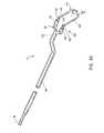
- the elongate bodyincludes a first shaft at its distal end, wherein the first shaft is bifurcated to form a first arm and a second arm.
- a first electrically insulating electrode support and a second electrode supportare disposed on the first and second arms, respectively.
- the first shaftincludes a first bend and a second bend. The bifurcated configuration of the first shaft, together with the first and second bends, facilitates viewing of the electrode assembly, from a proximal location during use of the probe.
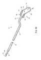
- each of the first and second electrode supportsincludes an axial portion and a curved portion, wherein the return electrode and the active electrode are suspended between the curved portions.
- the surface area of the return electrodeis greater than that of the active electrode.
- the surface area ratiois affected by the relative lengths and/or perimeter dimensions of the return and active electrodes.
- a filament of the return electrodeis longer than a filament of the active electrode.
- the circumference or perimeter of the return electrode filamentis greater than the circumference or perimeter of the active electrode filament.
- the active electrodelies in a first plane, and the return electrode lies in a second plane substantially parallel to the first plane, wherein the first plane is arranged at an acute angle with respect to the longitudinal axis of the probe.
- the return electrode filamentis separated from the active electrode filament by an electrode gap, which remains substantially constant over the entire length of the active electrode filament.
- an electrosurgical probe of the inventionincludes an attachment unit, coupled to the elongate body, wherein the attachment unit is adapted for removably attaching the probe to another surgical device.
- the attachment unitis adapted for attaching the probe to an endoscope, such that the probe is aligned with various components, such as an introducer sheath or an optical unit, of the endoscope.
- the probemay be removably attached to a resectoscope via the attachment unit such that a user of the probe can view the electrode assembly, and points distal thereto, from an eyepiece of the resectoscope, wherein the eyepiece is located proximal to the probe proximal end.
- the inventionprovides a method for ablation and/or resection of a target tissue, in which tissue is volumetrically removed via a cool ablation mechanism known as Coblation®, which involves molecular dissociation of tissue components.
- a method for resecting and harvesting a tissue fragment for tissue analysiswherein the tissue fragment is removed via electrosurgical ablation at a temperature in the range of about 45° C. to 90° C.
- the inventionprovides a method for transurethral resection of the prostate (e.g., TURP) in which prostate tissue is electrosurgically removed using a probe of the present invention.
- the probemay be manipulated in a plurality of different ways, depending on the condition of the patient and the treatment called for, according to different embodiments of the invention.
- the probemay be manipulated such that the electrode assembly exhibits a gentle brushing motion (e.g., reciprocal motion) with respect to a surface of the target tissue, whereby a relatively thin layer of tissue is vaporized during each stroke.
- the electrode assemblymay be applied more forcefully against the target tissue in a reciprocating motion, whereby one or more fragments or chips of tissue are electrosurgically resected, typically each proximal stroke of the probe resecting a single fragment of tissue. Tissue fragments removed in this manner may be optionally retrieved for biopsy.
- the probe distal endmay be inserted into the target tissue, perhaps to a depth of a few mm., or more, in order to remove one or more tissue fragments to be harvested for biopsy.
- all three, or any two, of the modes of manipulating the probe, as outlined above,can be combined in a single procedure.
- the target tissueis ablated (vaporized or resected) via a cool ablation mechanism involving plasma-induced molecular dissociation of tissue components.
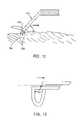
- the inventionincludes a method for ablation or resection of uterine tissue, such as polyps, leiomyomas, fibroids, and the like, in which the probe distal end is advanced towards the target tissue via the cervix of the uterus, and the target tissue is electrosurgically removed via the cool ablation mechanism (known as Coblation®D) involving molecular dissociation of tissue components to yield low molecular weight (e.g., gaseous) ablation by-products.
- Coblation®Dthe cool ablation mechanism
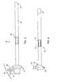
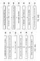
- FIG. 1is a perspective view of a representative electrosurgical system including an electrosurgical resectoscope, an electrically conductive fluid supply and an electrosurgical power supply constructed in accordance with the principles of the present invention
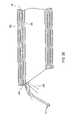
- FIG. 2is an enlarged perspective view of the resectoscope of FIG. 1 incorporating a return electrode oversheath and a resecting loop assembly according to the present invention
- FIG. 3illustrates an introducing sheath of the resectoscope of FIG. 2 ;
- FIG. 4illustrates the return electrode oversheath of FIG. 2 ;
- FIG. 5illustrates a cross-sectional view of the proximal portion of the resectoscope of FIG. 2 , illustrating the electrical connection with the return electrode oversheath;
- FIG. 6is a cross-sectional view of a proximal portion of the resectoscope in FIG. 2 , illustrating the electrical connection with the resecting loop assembly;
- FIG. 7is a top section view of a proximal portion of the resectoscope
- FIG. 8Aillustrates the resecting loop assembly of FIG. 2 ;
- FIG. 8Billustrates an alternative resecting loop assembly incorporating a return electrode
- FIG. 9is a section of a distal portion of the resecting loop assembly of FIG. 5 , illustrating a resecting loop electrode
- FIG. 10Ais a front view of the resecting loop electrode
- FIGS. 10B-10Dillustrate alternative geometries for the resecting loop electrode
- FIG. 11is an enlarged view of a resecting loop electrode
- FIG. 12is a schematic view illustrating the resecting loop electrode of FIG. 9 resecting a tissue portion at a target site;
- FIG. 13is an alternative embodiment of the resecting loop electrode of FIG. 9 ;
- FIG. 14is a transverse cross-sectional view of the resecting loop electrode of FIG. 9 ;
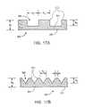
- FIGS. 15A and 15Bare transverse cross-sectional views of alternative loop electrodes according to the present invention.
- FIGS. 16A-16E , 17 A, 17 B, 18 A, 18 B, 19 , 20 A and 20 Billustrate alternative electrode configurations according to the present invention
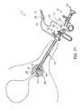
- FIG. 21illustrates a method of transurethral resection of prostate tissue with the electrosurgical system of FIG. 1 ;
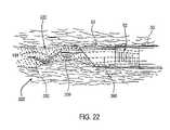
- FIG. 22is an enlarged view illustrating the resection of a prostate tissue portion with the resecting loop electrode of the present invention.
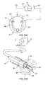
- FIGS. 23A-23Eillustrate another embodiment of the resecting loop electrode incorporating two active electrodes
- FIGS. 24A and 24Billustrate a resecting loop electrode incorporating two active electrodes connected to a common lead
- FIGS. 25A and 25Billustrate a resecting loop electrode with three active electrodes
- FIG. 26is a partial side cross-section of an alternative embodiment of the return electrode oversheath of FIG. 4 ;
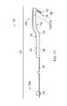
- FIG. 27shows a side view of an electrosurgical probe including a first shaft located at the probe distal end, according to another embodiment of the invention.
- FIG. 28is a perspective view of the first shaft of the probe of FIG. 27 ;
- FIG. 29shows an enlarged view of the distal end of the probe of FIG. 27 ;
- FIG. 30Ais an end view of an electrode assembly of an electrosurgical probe, according to one embodiment of the invention.
- FIG. 30Bschematically represents a first shaft and electrode assembly as seen along the lines 30 B- 30 B of FIG. 30A ;
- FIG. 30Cschematically represents an active electrode and a return electrode as seen along the lines 30 C- 30 C of FIG. 30A ;
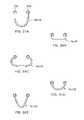
- FIGS. 31A-Eschematically represent different shapes of an active electrode and a return electrode of an electrosurgical probe, according to various embodiments of the invention.
- FIG. 32shows a side view of a probe distal end in which the electrode support extends preferentially along the active electrode, according to another embodiment of the invention.
- FIG. 33Ais a side view of an attachment unit disposed on a shaft of an electrosurgical probe, according to one embodiment of the invention.
- FIG. 33Bis an end view of the attachment unit of FIG. 33A , taken along the lines 33 B- 33 B;
- FIG. 34Aschematically represents a number of steps involved in a method of retrieving a fragment of tissue from a target tissue or organ, according to another embodiment of the invention.
- FIG. 34Bschematically represents a number of steps involved in a method of surgically removing a fragment of target tissue and vaporizing a portion of the target tissue, according to another embodiment of the invention.
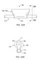
- FIGS. 35A-35Cillustrate various views of a double loop electrode assembly according to one embodiment of the present invention
- FIGS. 36A and 36Bshow enlarged cross-sectional and side views of the return electrode of the electrode assembly of FIGS. 35A-35C ;
- FIGS. 37A and 37Billustrate perspective and planar views of another double loop electrode assembly of the present invention.
- the present inventionprovides a system and method for selectively applying electrical energy to a target location within or on a patient's body, such as solid tissue or the like, including procedures within confined spaces such as the spaces around the articular cartilage between the femur and tibia and spaces between adjacent vertebrae in the patient's spine, and procedures that involve resection of relatively larger pieces of tissue.
- a target locationwithin or on a patient's body, such as solid tissue or the like
- procedures within confined spacessuch as the spaces around the articular cartilage between the femur and tibia and spaces between adjacent vertebrae in the patient's spine
- procedures that involve resection of relatively larger pieces of tissueFor convenience, the remaining disclosure will be directed primarily to the resection of prostate tissue, and the cutting, shaping or ablation of meniscal tissue located adjacent articular cartilage and soft tissue covering vertebrae.
- the system and methodcan be applied equally well to procedures involving other tissues of the body, as well as to other procedures including open surgery, laparoscopic surgery, thoracoscopic surgery, and other endoscopic surgical procedures.
- proceduresinclude oral procedures, including gingival tissues and mucosal tissues located in the mouth or epidermal tissue on the outer skin, dermatological procedures, such as the treatment of tumors, abnormal tissues, and the like or, canalizing or boring channels or holes through tissue, such as the ventricular wall during transmyocardial revascularization procedures.
- laminectomy/disketomy proceduresfor treating herniated disks, decompressive laminectomy for stenosis in the lumbosacral and cervical spine, posterior lumbosacral and cervical spine fusions, treatment of scoliosis associated with vertebral disease, foraminotomies to remove the roof of the intervertebral foramina to relieve nerve root compression and anterior cervical and lumbar diskectomies.
- the present inventionis also useful for resecting tissue within accessible sites of the body that are suitable for electrode loop resection, such as the resection of leiomyomas (fibroids) located within the uterus, as well as prostate tissue, and other diseased or hypertrophied tissue of a patient.
- the present inventionis particularly useful in procedures where the tissue site is flooded or submerged with an electrically conducting fluid, such as isotonic saline.
- an electrically conducting fluidsuch as isotonic saline.
- the electrosurgical probewill comprise a shaft having a proximal end and a distal end which supports one or more active electrode(s).
- the shaftmay assume a wide variety of configurations, with the primary purpose being to mechanically support the active electrode(s) and permit the treating physician to manipulate the electrode(s) from a proximal end of the shaft.
- the shaftwill be a narrow-diameter rod or tube, more usually having dimensions which permit it to be introduced into a body cavity, such as the arthroscopic cavity, through an associated trocar or cannula in a minimally invasive procedure, such as arthroscopic, laparoscopic, thoracoscopic, and other endoscopic procedures.
- the shaftwill typically have a length of at least 5 cm for oral procedures and at least 10 cm, more typically being 20 cm, or longer for endoscopic procedures.
- the shaftwill typically have a diameter of at least 1 mm and frequently in the range from 1 to 10 mm.
- the shaftmay have any suitable length and diameter that would facilitate handling by the surgeon.
- the shaftmay be rigid or flexible, with flexible shafts optionally being combined with a generally rigid external tube for mechanical support.
- Flexible shaftsmay be combined with pull wires, shape memory actuators, and other known mechanisms for effecting selective deflection of the distal end of the shaft to facilitate positioning of the electrode(s).
- the shaftwill usually include a plurality of wires or other conductive elements running axially therethrough to permit connection of the electrode(s) to a connector at the proximal end of the shaft. Specific shaft designs will be described in detail in connection with the figures hereinafter.
- the present inventionmay use a single active electrode or an electrode array distributed over a distal contact surface of a probe.
- the arrayusually includes (but is not limited to) a plurality of independently current-limited and/or power-controlled electrodes to apply electrical energy selectively to the target tissue while limiting the unwanted application of electrical energy to the surrounding tissue and environment resulting from power dissipation into surrounding electrically conductive liquids, such as blood, normal saline, and the like.
- the electrodesmay be independently current-limited by isolating the electrodes from each other and connecting each electrodes to a separate power source that is isolated from the other electrode terminals.
- the electrodesmay be connected to each other at either the proximal or distal ends of the probe to form a single wire that couples to a power source.
- each individual electrode in the electrode arrayis electrically insulated from all other electrodes in the array within the probe and is connected to a power source which is isolated from each of the other electrodes in the array or to circuitry which limits or interrupts current flow to the electrode when low resistivity material (e.g., blood or electrically conductive saline irrigant) causes a lower impedance path between the common electrode and the individual electrode terminal.
- low resistivity materiale.g., blood or electrically conductive saline irrigant
- the isolated power sources for each individual electrodemay be separate power supply circuits having internal impedance characteristics which limit power to the associated electrode terminal when a low impedance return path is encountered, may be a single power source which is connected to each of the electrodes through independently actuatable switches, or may be provided by independent current limiting elements, such as inductors, capacitors, resistors and/or combinations thereof.
- the current limiting elementsmay be provided in the probe, connectors, cable, controller or along the conductive path from the controller to the distal tip of the probe. Alternatively, the resistance and/or capacitance may occur on the surface of the active electrode(s) due to oxide layers which form selected electrode terminals (e.g., titanium or a resistive coating on the surface of metal).
- the inventionis not limited to electrically isolated electrode terminals, or even to a plurality of electrode terminals.
- the array of active electrode terminalsmay be connected to a single lead that extends through the probe shaft to a power source of high frequency current.
- the probemay incorporate a single electrode that extends directly through the probe shaft or is connected to a single lead that extends to the power source.
- the inventionmay also use current limiting means to apply electrical energy selectively to the target tissue while limiting the unwanted application of electrical energy to the surrounding tissue.
- the electrodemay be connected to current limiting elements or to circuitry which limits or interrupts current flow to the electrode when low resistivity material (e.g., blood or electrically conductive saline irrigant) causes a lower impedance path between the common electrode and the electrode.
- low resistivity materiale.g., blood or electrically conductive saline irrigant
- the current limiting elements or circuitrymay be configured to completely interrupt or modulate current flow to the electrode, for example, when a certain percentage of the electrode surface is in contact with low resistivity material.
- the current flowwill be modulated or completely interrupted when, for example, a large portion of the electrode surface is exposed to fluids and, therefore, not in contact with the target tissue. In this manner, current can be selectively applied to the target tissue, while minimizing current flow to surrounding fluids and adjacent non-target tissue structures.
- the active electrode(s)will have an active portion or surface with surface geometries shaped to promote high electric field intensity and associated high current density along the leading edges of the active electrode(s). Suitable surface geometries may be obtained by creating electrode shapes that include preferential sharp edges, or by creating asperities or other surface roughness on the active surface(s) of the electrodes. Electrode shapes according to the present invention can include the use of formed wire (e.g., by drawing round wire through a shaping die) to form electrodes with a variety of cross-sectional shapes, such as square, rectangular, L or V shaped, or the like. Electrode edges may also be created by removing a portion of the elongate metal electrode to reshape the cross-section.
- materialcan be removed along the length of a round wire or hollow, cylindrical wire to form D or C shaped electrodes, respectively, with edges facing in the cutting direction.
- materialcan be removed at closely spaced intervals along the length of the electrode to form transverse grooves, slots, holes, threads or the like along the electrode.
- the active electrode surface(s)may be modified through chemical, electrochemical or abrasive methods to create a multiplicity of surface asperities on the electrode surface. These surface asperities will promote high electric field intensities between the active electrode surface(s) and the target tissue to facilitate ablation or cutting of the tissue.
- surface asperitiesmay be created by etching the active electrodes with etchants having a pH less than 7.0, or by using a high velocity stream of abrasive particles (e.g., grit blasting) to create asperities on the surface of an elongated electrode.
- the active electrode surface(s)may be provided by assembling alternating layers of electrically conductive members (i.e., electrodes) and electrically insulating spacers.
- an active electrode having multiple circular edgesmay be constructed using alternating layers of concentric, thin metal washers (e.g., titanium, stainless steel or the like), having outside diameters D.
- the washersmay be separated by thin concentric insulating spacers (e.g., anodized aluminum, silicone rubber, ceramic, glass, glass ceramic, plastic, etc.) having an outside diameter D′ which is less than D so that the edges of the metal washers extend beyond the insulating spacers.
- the electrode assemblycan be constructed by placing the metal washers over a central, electrically conductive mandrel, which provides for electrical communication between the power source and the multiple metal “washer” shaped electrodes.
- the electrodesare preferably at the same source polarity since they are in contact with a common electrical lead (i.e., mandrel).
- the electrode assemblymay include a split mandrel having opposite polarities such that adjacent metal washers are at opposite polarities to effect one or more pairs of bipolar washer shaped electrodes.
- the metal electrodesmay have any shape suitable for the intended ablation or resection of tissue, e.g., square, circular, hexagonal, octagonal, triangular, etc.
- the perimeter of the thin metal electrodemay be stamped, machined, notched or otherwise modified to increase the electric field intensity at the working (outer) surface of the metal electrode.
- the metal electrodesmay be coated with an electrically insulating layer (e.g., silicone rubber, ceramic, glass or porcelain) of sufficient thickness to provide spacing between adjacent electrode members, whether the electrode assembly is monopolar or bipolar.
- the insulating coatingmay extend up to the perimeter of the metal electrode (e.g., washer), or it may be recessed from the perimeter to expose a greater portion of the edges of the electrodes.
- the active electrodeswill also have a “non-active” portion or surface(s) to selectively reduce undesirable current flow from the non-active portion or surface(s) into tissue or surrounding electrically conductive fluids (e.g., isotonic saline, blood or blood/non-conducting irrigant mixtures).
- tissue or surrounding electrically conductive fluidse.g., isotonic saline, blood or blood/non-conducting irrigant mixtures.
- the “non-active” electrode surface(s)may be coated with an electrically insulating material, such as silicone elastomer.
- an insulating materiale.g., SiO2 or Si3N4
- the method of the present inventioncomprises positioning an electrosurgical probe adjacent the target tissue so that at least one active electrode is brought into at least close proximity to the target site.
- a return electrodeis positioned within an electrically conductive fluid, such as isotonic saline, to generate a current flow path between the target site and the return electrode.
- High frequency voltageis then applied between the active and return electrodes through the current flow path created by the electrically conductive fluid in either a bipolar or monopolar manner.
- the probemay then be translated, reciprocated or otherwise manipulated to cut the tissue or effect the desired depth of ablation.
- the current flow pathmay be generated by submerging the tissue site in an electrically conductive fluid (e.g., during arthroscopic surgery and the like), or by directing an electrically conductive fluid along a fluid path past the return electrode and to the target site to generate the current flow path between the target site and the return electrode.
- This latter methodis particularly effective in a dry environment (i.e., the tissue is not submerged in fluid), such as open, endoscopic or oral surgery, because the electrically conductive fluid provides a suitable current flow path from the target site to the return electrode.
- a more complete description of an exemplary method of directing electrically conducting fluid between the active and return electrodesis described in commonly assigned U.S. Pat. No. 5,697,281, the contents of which are incorporated herein by reference.
- the active electrode(s)are disposed at the distal end of the probe and the return electrode is spaced from the active electrode and enclosed within an insulating sheath. This arrangement minimizes exposure of the return electrode to surrounding tissue and minimizes possible shorting of the current between the active and return electrodes.
- the probemay be passed through a cannula while viewing of the operative site is provided through the use of an endoscope disposed in a separate cannula.
- the probemay be attached to, or integral with, an endoscope.
- a high frequency voltageis applied between the active portion of the active electrode(s) and the return electrode to develop high electric field intensities in the vicinity of the target tissue.
- the high electric field intensitieslead to electric field induced molecular breakdown of target tissue through molecular dissociation (rather than thermal evaporation or carbonization of tissue).
- Applicantbelieves that the tissue structure is volumetrically removed through molecular disintegration of larger organic molecules into smaller molecules and/or atoms, such as hydrogen, oxides of carbon, hydrocarbons and nitrogen compounds. This molecular disintegration completely removes the tissue structure, as opposed to dehydrating the tissue material by the removal of water from within the cells of the tissue, as is typically the case with electrosurgical desiccation.
- the high electric field intensitiesmay be generated by applying a high frequency voltage that is sufficient to vaporize the electrically conductive fluid over at least a portion of the active electrode(s) in the region between the distal tip of the active electrode and the target tissue. Since the vapor layer or vaporized region has a relatively high electrical impedance, it minimizes current flow into the electrically conductive fluid. This ionization, under the conditions described herein, induces the discharge of energetic electrons and photons from the vapor layer and to the surface of the target tissue. A more detailed description of this phenomenon can be found in commonly assigned U.S. Pat. No. 5,697,882 the complete disclosure of which is incorporated herein by reference.
- the voltage applied between the return electrode and the active electrode(s)will be at high or radio frequency, typically between about 5 kHz and 20 MHz, usually being between about 30 kHz and 2.5 MHz, and more typically being between about 50 kHz and 400 kHz.
- the RMS (root mean square) voltage appliedwill usually be in the range from about 5 volts to 1000 volts, typically being in the range from about 50 volts to 800 volts, and more typically being in the range from about 100 volts to 400 volts.
- the vaporized electrically conductive fluidis in the form of a plasma.
- the peak-to-peak voltagewill be in the range of from about 200 to 2000 volts, usually in the range of 300 to 1600 volts, and more typically in the range of 500 to 1200 volts.
- a preferred power source of the present inventiondelivers a high frequency voltage selectable to generate average power levels ranging from tens of milliwatts to tens of watts up to hundreds of watts per electrode, depending on the number of electrodes, the target tissue being ablated, the rate of ablation desired or the maximum allowed temperature selected for the probe tip.
- the target tissueis exposed to a temperature in the range of from about 45° C. to 90° C., and more typically from about 60° C. to 75° C.
- the power sourceallows the user to select the voltage level according to the specific requirements of a particular open surgery, oral surgery, dermatological procedure, percutaneous, endoscopic, or other surgical procedure.
- the power sourcemay be current limited or otherwise controlled so that undesired heating of electrically conductive fluids or other low electrical resistance media does not occur.
- current limiting inductorsare placed in series with each independent electrode terminal, where the inductance of the inductor is in the range of 10 uH to 50,000 uH, depending on the geometry and size of the electrode(s), the electrical properties of the target tissue, the desired ablation rate and the operating frequency.
- capacitor-inductor (LC) circuit structuresmay be employed, as described previously in co-pending PCT application No. PCT/US94/05168, the complete disclosure of which is incorporated herein by reference. Additionally, current-limiting resistors may be selected.
- these resistorswill have a large positive temperature coefficient of resistance so that, as the current level begins to rise for any individual electrode in contact with a low resistance medium (e.g., saline irrigant), the resistance of the current limiting resistor increases significantly, thereby minimizing the power delivery from the electrode into the low resistance medium (e.g., saline irrigant).
- a low resistance mediume.g., saline irrigant
- regulated current flow to each electrode terminalmay be provided by a multi-channel power supply.
- a substantially constant current level for each individual electrode terminalwithin a range which will limit power delivery through a low resistance path, e.g., isotonic saline irrigant, and would be selected by the user to achieve the desired rate of cutting or ablation.
- Such a multi-channel power supplythus provides a substantially constant current source with selectable current level in series with each electrode terminal, wherein all electrodes will operate at or below the same, user selectable maximum current level. Current flow to all electrode terminals could be periodically sensed and stopped if the temperature measured at the surface of the electrode array exceeds user-selected limits. Particular control system designs for implementing this strategy are well within the skill of the art.
- Yet another alternative embodimentinvolves the use of a power supply for energizing one or more electrodes having use of one or more channels of user-selectable voltage levels.
- the channelswould incorporate an active control mechanism for limiting current levels below a pre-selected maximum level.
- the pre-selected maximum current leveldepends on the size and configuration of the electrode(s), and may be “factory” set or user selectable.
- an indicator devicemay be included in the probe (e.g., a resistor having a resistance value which corresponds to the maximum current level appropriate to a specific electrode configuration) such that the power supply can (1) first measure the indicator device value (e.g., measure the resistance of the indicator) contained within the probe; and (2) then set the maximum current level which corresponds to that resistance value.
- a range of probe designshaving greatly differing electrode size(s) and configuration(s) can be energized since the power supply will automatically adjust the maximum current level to correspond to each particular electrode size and configuration.
- Yet another alternativeinvolves the use of one or several power supplies which allow one or several electrodes to be simultaneously energized and which include active control means for limiting current levels below a preselected maximum level.
- active control meansfor limiting current levels below a preselected maximum level.
- only one or several electrodeswould be simultaneously energized for a brief period.
- Switching meanswould allow the next one or several electrodes to be energized for a brief period.
- a resistance measurement means or devicemay be employed for each electrode prior to the application of power wherein a (measured) low resistance (below some preselected level) will prevent that electrode from being energized during a given cycle.
- the sequential powering and control scheme of the present inventionwould function in a manner similar to an automobile distributor.
- an electrical contactrotates past terminals connected to each spark plug.
- each spark plugcorresponds to the exposed surface of each of the electrodes.
- the present inventionincludes the means to measure the resistance of the medium in contact with each electrode and cause voltage to be applied only if the resistance exceeds a preselected level.
- the distal end of the probe or the active electrode(s)may be maintained at a small distance away from the target tissue surface. This small spacing allows for the continual resupply of electrically conductive fluid into the interface between the active electrode(s) and the target tissue surface. This continual resupply of the electrically conductive fluid helps to ensure that the thin vapor layer will remain between the active electrode(s) and the tissue surface. In addition, dynamic movement of the active electrode(s) over the tissue site allows the electrically conductive fluid to cool the tissue surrounding recently ablated areas to minimize thermal damage to this surrounding tissue.
- the active electrode(s)may be spaced about 0.02 to 2 mm from the target tissue, and typically about 0.05 to 0.5 mm from the target tissue, during the ablation process.
- One method of maintaining this spaceis to translate and/or rotate the probe transversely relative to the tissue, i.e., using a light brushing motion, to maintain a thin vaporized layer or region between the active electrode and the tissue.
- the probemay be advanced axially so that the active electrode(s) penetrate the target tissue to a suitable depth.
- the active electrode or the electrode arraywill have an exposed length in the range from about 2.5 to 12.5 mm. With electrode lengths within this range, applicant has found that current-limiting inductors having inductance values of about 0 to 100 uH, preferably about 25 to 50 uH, are suitable for establishing the requisite conditions for selective ablation described above (i.e., the generation of sufficient electric field intensities to form a vapor layer in the electrically conductive fluid and to induce the discharge of energy through the vapor layer to ablate tissue while precisely controlling the extent of ablation and minimizing damage to non-target tissue.
- the active electrode(s)may have a substantially smaller exposed length away from the probe than described above (on the order of about 0 to 0.5 mm). This configuration is described in commonly assigned U.S. Pat. No. 5,697,882, the complete disclosure of which is incorporated herein by reference.
- electrosurgical system 11constructed according to the principles of the present invention.
- electrosurgical system 11generally comprises an electrosurgical resectoscope 10 incorporating a resecting loop assembly 12 with an active electrode (not shown in FIG. 1 ), and a return electrode oversheath 16 circumscribing a portion of the resecting loop assembly 12 .
- the resectoscope 10is connected to a power supply 28 for providing high frequency voltage to the active electrode and a liquid source 21 for supplying electrically conducting fluid 50 to a target tissue (see FIGS. 21 and 22 ).
- a liquid supply tube 15removably couples liquid source 21 , (e.g., a bag of fluid elevated above the surgical site or having a pumping device), with return electrode oversheath 16 .
- liquid source 21e.g., a bag of fluid elevated above the surgical site or having a pumping device
- a manual control valve 17may also be provided between the proximal end of return electrode oversheath 16 and supply tube 15 to allow the surgical team to regulate the flow of electrically conductive fluid 50 .
- Power supply 28has a selector 30 for varying the applied voltage level.
- Power supply 28also includes a mechanism for energizing the active electrode of resectoscope 10 through the depression of a first pedal 39 in a foot pedal 37 positioned close to the user.
- the foot pedal 37will usually include a second pedal 38 for remotely adjusting the energy level applied to active electrode 14 ( FIG. 2 ).
- first pedal 39will apply a higher voltage level suitable for cutting and ablating tissue
- second pedal 38will apply a lower voltage level suitable for coagulating and sealing tissue, such as a transected blood vessel (discussed in further detail below).
- a specific design of one power supply which may be used with the electrosurgical probe of the present inventionis described in parent application PCT U.S. 94/051168, the full disclosure of which has previously been incorporated herein by reference.
- resectoscope 10represents a conventional or specialized resectoscope that is adapted for use with resecting loop assembly 12 and return electrode oversheath 16 , according to the present invention.
- Existing resectoscopes useful with the present inventioncan be found, for example, under the trade names of USA Elite System Resectoscope from Circon/ACMI of Stamford, Conn. and OES Resectoscope from Olympus Corporation of Lake Success, N.Y. Loop assembly 12 and oversheath 16 may also be used without a resectoscope. In this configuration, the surgeon may use other means for viewing the surgical site, such as a separate endoscope.
- Resectoscope 10generally includes a proximal handle 64 , and an introducing sheath 60 ( FIG. 3 ) having a hollow, tubular shaft 62 for axially receiving loop assembly 12 .
- Sheath 60also includes a proximal hub 98 for connecting sheath 60 to handle 64 and return electrode oversheath 16 (discussed in detail below).
- handle 64includes a viewing assembly 66 , an irrigant/suction assembly 68 and an actuation assembly 70 for axially reciprocating loop assembly 12 relative to shaft 62 .
- actuation assembly 70includes a coupling housing 72 having an outer knob or thumbscrew 74 that can be tightened to secure a proximal connector leg 76 of loop assembly 12 to an electrically conducting inner sleeve member 78 of coupling housing 72 ( FIG. 7 ).
- Sleeve member 78electrically couples leg 76 to a resecting loop terminal 80 ( FIG. 6 ), which can be removably coupled to power supply 28 to provide power to loop assembly 12 (discussed in further detail below).
- Coupling housing 72is axially translatable relative to introducing sheath 60 so that resecting loop assembly 12 can be axially translated relative to the distal end 94 of tubular shaft 62 (see FIG.
- resectoscope 10will usually include a finger loop 82 and a thumb loop 84 suitably connected to housing 72 for reciprocating housing 72 and loop assembly 12 relative to the distal end 94 of shaft 62 .
- control means for axially reciprocating loop assembly 12can be utilized with the present invention, such as rotatable knobs, trigger buttons, and the like.
- electrosurgical system 11will preferably include a return electrode oversheath 16 for completing the current path between active electrode 14 and power supply 28 (discussed in detail below). It should be made clear, however, that the present invention is not limited to a bipolar modality and, may utilize a monopolar mode. In this configuration, return electrode oversheath 16 is not required. Instead, voltage is applied between an active electrode 14 and a dispersive electrode plate externally attached to the patient's skin such that electric current flows from active electrode 14 , through the patient's body, to the dispersive electrode.
- Return electrode over sheath 16generally includes an electrically conducting, hollow shaft 86 coupled to a proximal housing 88 with a suitable epoxy adhesive, for example.
- the inner and outer surfaces of shaft 86are covered with an electrically insulating layer 90 over the entire length of shaft 86 except for an exposed portion 92 at the shaft distal end, which remains exposed to provide a current path from active loop assembly 12 (discussed below).
- Electrically insulating layer 90may comprise a heat shrinkable tubing material, such as KynarTM, or it may be a deposited coating, such as ParyleneTM, polytetrafluoroethylene, polyimide, flourinated ethylene-propylene or the like.
- the electrically insulating layer 90 over return electrode shaft 86prevents direct electrical contact between the return electrode and any adjacent body structure or the surgeon. Such direct electrical contact between a body structure (e.g., tendon) and an exposed return electrode member could result in unwanted heating of the structure at the point of contact causing necrosis. If return electrode oversheath 16 is being used with an electrically insulating resectoscope sheath (e.g., a plastic tubular sheath), the inner surface of shaft 86 may remain exposed (i.e., electrically insulating layer 90 may be omitted).
- an electrically insulating resectoscope sheathe.g., a plastic tubular sheath
- Return electrode shaft 86will have an inner diameter large enough to slide shaft 86 over tubular shaft 62 of introducing sheath 60 ( FIG. 5 ). Distal end portion 94 of shaft 62 is introduced through an opening 96 in proximal housing 88 and axially delivered through return electrode shaft 86 until housing 88 abuts against proximal hub 98 of introducing sheath 60 .
- Return electrode oversheath 16further includes a fastener, such as a thumbscrew 100 , to secure return electrode oversheath 16 to introducing sheath 60 . As shown in FIG.
- return electrode shaft 86has an opening 102 aligned with thumbscrew 100 so that the thumbscrew 100 can engage tubular shaft 62 of introducing sheath 60 .
- Thumbscrew 100preferably comprises an electrically insulating material, such as UltemTM, to minimize electrical shock to the surgeon during use of resectoscope 10 .
- resectoscope 10is electrically connected to power supply 28 with cable 34 , which is removably connected to power supply 28 by a power supply connector plug 26 .
- Cable 34includes an adaptor 130 that branches into a first lead 132 which is removably connected via plug 134 to a return electrode terminal 136 , e.g., via a minibananna plug, and a second lead 138 which is removably connected via plug 140 to resecting loop terminal 80 ( FIGS. 6 , 21 ).
- return electrode plug 134includes a recessed electrical receptacle 142 which permits plug 134 to be inserted into a cavity 144 of return electrode housing 88 . This provides a fluid-tight seal between housing 88 and plug 134 to minimize the possibility of electrical shock to the surgeon or patient if the controller is energized prior to the complete connection of plug 134 and electrode terminal 136 .
- handle 64 of resectoscope 10will also usually include a viewing assembly 66 and an irrigant/suction assembly 68 .
- viewing assembly 66includes a hub 150 , a telescopic lumen 152 extending through shaft 62 of introducing sheath 60 and an eyepiece 154 coupled to lumen 152 to permit viewing of the target site by the physician.
- a cameramay be attached to the proximal end of hub 150 to allow display of the surgical site on a video monitor.
- a fiberoptic light source(not shown) is typically attached to hub 150 to illuminate the target site.
- Irrigant/suction assembly 68includes proximal hub 98 of introducing sheath 60 , and a connector 160 extending from hub 98 and coupled to supply line 15 for introducing a sterile irrigant, typically isotonic saline, to the surgical site.
- Connector 160is fluidly coupled to an axial lumen 162 within shaft 62 (see FIG. 3 ). Fluid may also be withdrawn through axial lumen 162 or a second lumen (not shown) within shaft 62 to withdraw unwanted or excess fluids from the surgical site and to facilitate the surgeon's view.
- Loop assembly 12generally includes an electrically insulating hollow shaft 180 with proximal connection leg 76 and a distal active electrode assembly 182 .
- Active electrode assembly 182includes a bifurcated support member 184 having a pair of hollow arms 186 , 188 extending from a distal end 190 of shaft 180 .
- a hollow, electrically insulating tubular member 192extends from each arm 186 , 188 of bifurcated support member 184 , and a tubular resecting loop electrode 194 extends from each tubular member 192 .
- Tubular members 192will comprise a suitable insulating material (e.g., a silicone rubber, ceramic or glass material, such as alumina, zirconia and the like).
- a suitable insulating materiale.g., a silicone rubber, ceramic or glass material, such as alumina, zirconia and the like.
- Such support materialshave one or more of the following characteristics: good electrically insulating properties, high flexural modulus, resistance to carbon tracking, biocompatibility, and high melting point.
- a resecting loop assembly 12 ′may incorporate the return electrode so that only a single instrument is required for bipolar resection of tissue (i.e., a return electrode oversheath is not required).
- resecting loop assembly 12 ′includes an electrically conducting shaft 180 ′ covered with an outer electrically insulating layer 181 .
- Shaft 180 ′includes a distal exposed portion 183 for completing the current return path with active electrode assembly 182 , and a proximal exposed portion 185 for connecting return electrode 180 to power supply 28 .
- resecting loop electrode 194comprises an elongate loop body 196 having first and second ends 198 , 199 coupled to and extending within tubular members 192 .
- Resecting loop electrode 194is preferably composed of a corrosion resistant, electrically conductive metal or alloy, such as platinum, titanium, tantalum, tungsten, stainless steel, nickel and cobalt-based alloys and the like. It should be understood that loop electrode 194 may have configurations other than that described above and shown in FIGS. 8A-11 .
- the electrodefits within the available space within the working end of a resectoscope, which generally includes fiber optic or “glass rod” optical viewing and lighting means, articulating resecting means and irrigant supply ports; (2) the electrode is shaped and sized to allow the surgeon to view the tissue site; and (3) the electrode is configured to cut chips or small portions of tissue from the target site.
- the “loop” electrodemay have a variety of shapes, such as semi-circular, square, triangular, rectangular, or multi-sided geometry (see FIGS. 10B-10D , for example).
- a semi-circular or U-shaped loop electrode(e.g., FIG. 10A ) has the advantage that it easily fits within the cylindrical bore of conventional resectoscopes. In addition, this shape tends to facilitate good visibility for the surgeon, and it produces rapid resection of tissue.
- Loop electrode 194may also comprise a plurality of active electrodes that are either coupled together or electrically isolated from each other (discussed below). In the latter case, electrosurgical system 11 may include current limiting elements or circuitry to independently limit current to the electrodes based on the impedance between each active electrode and the return electrode, as described above.
- electrical connections 200such as lead wires, metal tubes or the like, extend through one or both arms 186 , 188 of support member 184 and shaft 180 to electrically couple one or both ends 198 , 199 of resecting loop electrode 194 with connector leg 76 .
- Electrical connections 200are coupled to loop electrode 194 and connector leg 74 using crimping, soldering, welding or other suitable methods.
- Electrical connections 200are preferably covered with an insulating sheath (not shown) except for exposed distal and proximal portions of connections 200 that are coupled to loop electrode 194 and leg 74 , respectively.
- resecting loop electrode 194preferably has a substantially C-shaped transverse cross-section along its entire length to form first and second ends 204 , 206 that define a slot 208 therebetween.
- Ends 204 , 206each define relatively sharp edges 210 that promote high electric field intensities around ends 204 , 206 to enhance the tissue cutting capabilities of resecting loop assembly 12 .
- Ends 204 , 206 and edges 210 of loop electrode 194form an active portion of electrode that promotes sufficiently high electric field intensities sufficient to reach the threshold conditions for formation of a vapor layer in the electrically conductive liquid, as discussed above.
- resecting loop electrode 194is preferably oriented so that ends 204 , 206 are generally parallel to the cutting direction (i.e., facing the target tissue, see FIG. 12 ). This orientation facilitates the formation of a vapor layer between ends 204 , 206 and the target tissue and directs the energy induced from the vapor layer to the target tissue.
- loop electrode 194further includes a non-active portion 212 on the opposite side from ends 204 , 206 .
- Non-active portion 212preferably defines a relatively smooth surface to reduce the electric field intensities around portion 212 , thereby minimizing undesirable current flow into fluids and surrounding tissue.
- non-active portion 212may include an insulating layer (not shown) to further minimize the possibility of undesirable tissue damage. This configuration allows the surgeon to more selectively ablate tissue at the target site.
- loop electrode 194is formed from a hollow tube that is filed or ground down to form a semi-circular, U-shaped or C-shaped transverse cross-section.
- the filing operationcreates four relatively sharp corners 210 along the length of the bipolar loop electrode 194 , as shown in FIG. 11 .
- the thin metal wall tubingis filed or ground up to, but not exceeding the diametral line of the tubing.
- loop electrode 194will have an outside diameter of about 0.005 to 0.03 inch and a wall thickness of about 0.003 to 0.01 inch.
- the resecting or active loop electrodecomprises a 0.013 diameter molybdenum wire loop and the return electrode comprises a 0.020 molybdenum wire loop (see embodiments below).
- FIGS. 15A and 15Billustrate alternative embodiments of bipolar loop electrode 194 .
- loop electrode 194may have a D-shaped cross-section having a substantially planar active surface 300 .
- electrode 194is preferably fabricated from a solid round wire that is shaped (e.g., ground or filed), substantially as described above for the D-shaped electrode configuration, to form electrode edges 210 .
- electrode 194may also have a double slotted configuration that is generally formed by grinding both sides of a hollow tube.
- loop electrode 194may be constructed from a formed wire (e.g., a round wire that has been drawn through a shaping die) shaped to create corners on the periphery of the extended loop electrode surface.
- FIGS. 16A-16Eillustrate examples of electrode cross-sectional shapes that may be used with the present invention.
- FIGS. 17A , 17 B, 18 A, 18 B and 19illustrate other alternatively shaped electrodes having transverse grooves or slots formed therein to promote high electric field intensities.
- loop electrode 302comprises an elongate body 304 having a plurality of spaced, transverse slots 306 ( FIG. 17A ) or grooves 308 ( FIG. 17B ) formed therein.
- the electrode edges 210 of slots 306 and grooves 308will generally form the “active” portion of the electrode, while an opposing, substantially planar surface 310 forms the “non-active” portion of the electrode 302 .
- An insulating layermay be formed over surface 310 to prevent undesirable current flowing from this surface 310 to adjacent tissue.
- electrode 302 ′may include grooves 312 on both sides so that both sides of electrode 302 ′ are “active”, as shown in FIG. 18A by virtue of the electrode edges 210 formed by the grooves or slots 312 .
- electrode 314may have a “necklace” shape, in which electrode members are pre-shaped, perforated and then placed on an elongate support member (similar to beads on a necklace).
- electrode 314includes an elongate support member 316 , which may comprise an electrically conducting or insulating material, and a plurality of electrode disks 318 having an inner hole for receiving support member 316 . Electrode disks 318 may be in contact with each other or longitudinally spaced from each other. In the latter configuration, support member 316 will be electrically conducting to electrically connect the disks 318 with each other. Referring to FIG.
- each electrode disk 318may be separated from each other by an insulating spacer 320 .
- the electrodes 318may be electrically isolated from each other so that current limiting elements can be utilized to minimize undesirable current flow into surrounding fluids, as described above.
- FIGS. 20A and 20Billustrate further alternative embodiments of the loop electrode according to the present invention.
- a formed wirehas been shaped (e.g., by a shaping die) to form a “V” shape electrode 330 . Since the ends 331 , 332 of the “V” will promote high electric field intensities, they will preferably face in the cutting direction.
- an insulating layer 334is formed onto the backside 335 of the “V”.
- FIG. 20Billustrates a “C” shaped electrode 336 having ends 337 , 338 facing the cutting direction and an insulating layer 340 covering an opposite side 342 of electrode 336 .
- resecting loop electrode 194is aligned with a plane forming an obtuse angle with the longitudinal axis of shaft 180 .
- the obtuse angleis usually about 110° to about 170°, preferably about 120° to about 150°.
- this orientationsignificantly facilitates initiating the requisite conditions for forming the vapor layer and inducing the discharge of energy therefrom. More specifically, in this orientation, a greater fraction of the surface area and length of loop electrode 194 is in direct contact with the tissue. As such, a greater length of the resection loop is employed thereby directing a greater fraction of the applied energy to the tissue to be resected.
- the portion of the length of the electrode in contact with tissueis at least about 30 to 40% greater than the tissue-contacting portion of loop electrodes having a right angle (90%) orientation (see FIG. 13 ).
- a smaller fraction of loop electrode 194is exposed to electrically conducting fluid surrounding the tissue, which minimizes undesirable current flow through this fluid.
- FIGS. 21 and 22a method for applying electrical energy to a target tissue in the patient's body will now be described.
- an exemplary procedure for treating an enlarged prostate 222 with electrosurgical system 11will be described.
- Introducing sheath 60 , return electrode oversheath 16 , and resecting loop assembly 112are introduced transurethrally to the urethra 226 within prostate 222 .
- return electrode oversheath 16will not be introduced, and a dispersive electrode (not shown) will be externally attached to the patient's skin.
- voltagecan be applied from power supply 28 (see FIG.
- the cutting and resection of prostatic tissue 222is achieved by engaging resecting loop electrode 194 against the prostatic tissue or positioning loop electrode 194 in close proximity to the prostatic tissue while simultaneously applying voltage from power supply 28 and axially displacing loop electrode 194 towards the distal end of introducing sheath 60 as illustrated by resection vector 299 in FIG. 22 .
- electrically conducting irrigante.g., isotonic saline
- liquid supply 21e.g., isotonic saline
- the electrically conductive fluidprovides a pathway for electrical current flow between prostatic tissue 222 and exposed portion 92 , as illustrated by the current flux lines 360 in FIG. 22 .
- the design of the surface geometry of resecting loop electrode 194promotes high current densities at the surface of electrode 194 , especially at the shaped edges. In contrast, the current density decreases rapidly with distance from the surface of resecting loop electrode 194 . Since the length of the exposed portion 92 of return electrode oversheath 16 will be about 2 to 4 cm, the surface area of exposed portion 92 will be about 5 to 10 cm2. In contrast, the surface area of the resecting loop electrode 194 is about 0.003 cm2. As a result, the current density at exposed portion 92 is 1,700 to 3,400 times smaller than that at resecting loop electrode 194 , resulting in current density levels below the threshold of injury to living tissue.
- resecting loop electrode 194may be used specifically for coagulating and sealing a transected blood vessel by engaging the tissue at the locus of the bleeding vessel and lightly applying pressure while simultaneously applying a lower voltage level, i.e., a voltage level which is below the threshold for effecting cutting or resection of tissue.
- an applied voltage level of less than 500 volts (peak-to-peak), preferably less than 400 volts (peak-to-peak)will be sufficient to effect coagulation of transected blood vessels without cutting or resection of tissue.
- This dual mode of operation of resecting loop 112is preferably accomplished by providing dual footpedal 37 , which includes a cutting mode pedal 39 and a coagulation mode pedal 38 .
- system 111may be switched between the two modes using voltage control buttons 30 ( FIG. 1 ).
- telescopic lumen 152( FIG. 21 ) and the attached return electrode oversheath 16 can be withdrawn from introducing sheath 160 of resectoscope 10 by releasing a mechanical locking member 350 .
- the open lumen of introducing sheath 60can be used to remove one or more tissue fragments 352 ( FIG. 22 ) formed during the resection process.
- FIGS. 23A-23Eillustrate another embodiment of a resecting loop assembly 12 ′ incorporating two electrodes 560 , 562 which are electrically isolated from direct contact with each other by an insulating spacer 564 .
- Electrodes 560 , 562may comprise solid wires, hollow tubes, or any of the cross-sectional shapes and configurations discussed above to afford regions of high electric field intensity. Similar to the above embodiments, the proximal ends of electrodes 560 , 562 extend from electrically insulating tubular members 192 , which extend from hollow arms 186 , 188 of a bifurcated support member 184 . As shown in FIGS.
- electrodes 560 , 562are each connected to an electrically conducting lead 566 , 567 which, in turn, connect to first and second poles 568 , 570 , respectively, of the output of power supply 28 .
- currentillustrated by current flux lines 572
- the currenteffects tissue cutting, ablation, shrinkage and/or coagulation in these regions between electrodes 560 , 562 .
- a return electrodeis not utilized in this arrangement and, therefore, return electrode oversheath 16 is not necessary.
- FIGS. 24A and 24Billustrate another embodiment of a resecting loop assembly 12 ′′ in which electrodes 560 , 562 are each connected to an electrically conducting lead wire 574 , 576 which are connected to a common lead 578 .
- the distal end of common lead 578is connected to a first pole 568 of power supply.
- return electrode oversheath 16(see FIG. 4 ) will be coupled to second pole 570 of power supply 28 .
- FIGS. 25A and 25Billustrate yet another embodiment of a resecting loop assembly 12 ′′′ incorporating three electrodes 600 , 602 , 604 assembled to form loop electrode 194 ′. Lead wires electrically couple electrodes 600 , 602 , 604 to power supply 28 .
- Electrodes 600 - 604are mechanically spaced and electrically insulated from each other by insulating spacers 612 , 614 . Similar to previous embodiments, electrodes 600 and 604 extend from electrically insulating tubular members 192 , which extend from hollow arms 186 , 188 of a bifurcated support member 184 .
- FIG. 25Billustrates the current flux lines 620 , 622 for one electrical arrangement for connected electrodes 600 - 604 to power supply 28 .
- electrodes 600 , 604are connected to first pole 568 of power supply 28 (see FIGS. 24D and 24E ) in a manner similar to that described above for resecting loop assembly 12 ′ and electrode 602 is coupled to second pole 570 of power supply 28 (i.e., exposed portion 92 of return electrode oversheath 16 is not utilized in this arrangement).
- FIG. 25Aillustrates the current flux lines 624 , 626 , 628 for another electrical arrangement for resecting loop assembly 12 ′′′.
- electrodes 600 , 602 and 604are independently connected to first pole 568 of power supply 28 and return electrode oversheath 16 is coupled to second pole 570 (see FIGS. 24A and 24B ). As shown, current flows independently between each electrode 600 , 602 and 604 and exposed portion 92 of return electrode oversheath 16 .
- FIG. 26illustrates another embodiment of electrosurgical system 11 in which a return electrode oversheath 16 ′ is completely covered with inner and outer insulating layers 606 , 680 except for an exposed portion 610 at the distal end of return electrode oversheath 16 ′ that extends beyond the inner insulating layer 606 .
- the exposed portion 610generates a current flow path 612 between resecting loop electrode 12 and exposed portion 610 of return electrode oversheath 16 ′.
- return electrode oversheath 16 ′is used in conjunction with and positioned over an insulated resecting loop shaft (not shown), the return electrode oversheath 16 ′ will be insulated on its outer surface only.
- the sheath of the resectoscopecan be replaced with a sheath having the insulation features and return electrode arrangement shown in FIG. 26 such that an additional oversheath return electrode is not required.
- FIGS. 27-33illustrate an electrosurgical instrument having a “double loop” electrode configuration.
- FIG. 27shows a side view of an electrosurgical probe 700 including a probe proximal end 700 a , a probe distal end 700 b , and an elongate body portion 710 having first, second, and third shaft portions 730 , 740 , and 750 , respectively.
- First shaft portion 730includes a first bend 736 and a second bend 738 .
- First shaft 730is bifurcated to provide a first arm 732 and a second arm 734 ( FIG. 28 ).
- first and second bends 736 , 738are distal to the point of bifurcation.
- Probe 700further includes first and second electrode supports 722 a , 722 b , respectively, arranged on the distal end of first and second arms 732 , 734 (e.g., FIG. 28 ).
- First and second electrode supports 722 a , 722 beach comprise an electrically insulating material, such as a silicone rubber, a ceramic, or a glass.
- first and second electrode supports 722 a , 722 beach include a curved portion 723 (e.g., FIG. 29 ). In one embodiment, curved portion 723 forms an acute angle with respect to the longitudinal axis of probe 700 .
- An active electrode 724 and a return electrode 726are disposed between curved portion 723 of each of first and second electrode supports 722 a , 722 b . Active electrode 724 is located proximal to return electrode 726 .
- the configuration of probe 700including the bifurcation of first shaft portion 730 together with first and second bends 736 , 738 , allows a user to view active and return electrodes 724 , 726 , and points distal thereto, from a substantially axial location proximal to probe proximal end 700 a .
- elongate body 710may be at least partially encased within a sheath, which may be electrically insulating.
- a handle(not shown in FIG. 27 ) may be affixed at probe proximal end 700 a.
- active electrode 724 and return electrode 726are arranged at an acute angle with respect to the longitudinal axis of probe 700 (e.g., FIG. 29 ).
- active electrode 724is in the form of a loop or partial loop and lies in a first plane
- return electrode 726is also in the form of a loop or partial loop and lies in a second plane distal to the first plane, wherein the first and second planes are parallel or substantially parallel to each other.
- Active electrode 724 and return electrode 726may each have various shapes, such as semicircular or U-shaped ( FIGS. 31A-E ).
- each of active electrode 724 and return electrode 726comprises a length of a refractory, electrically conducting wire.
- each of active electrode 724 and return electrode 726may be composed of a metal such as molybdenum, platinum, iridium, titanium, tantalum, tungsten, stainless steel, copper, nickel, and the like, or their alloys.
- at least one of active electrode 724 and return electrode 726comprises an alloy of platinum with another metal such as tungsten, iridium, or molybdenum.
- the composition of active electrode 724 and return electrode 726is at least to some extent a matter of design choice.
- active electrode 724may comprise molybdenum or a molybdenum alloy
- return electrode 726may comprise stainless steel.
- one or more of active electrode 724 and return electrode 726may be coated with a material such as chromium or titanium nitride.
- probe 700typically includes a bipolar connector unit 770 for coupling active electrode 724 and return electrode 726 to opposite poles of a high frequency power supply (e.g., FIG. 1 ).
- bipolar connector unit 770is disposed on the proximal portion of elongate body 710 , e.g., on third shaft portion 750 .
- probe 700further includes an attachment unit 760 for removably attaching probe 700 to another instrument, such as a resectoscope, or other endoscope.
- attachment unit 760comprises a clamp affixed to elongate body 710 at second shaft 740 ( FIGS. 33A-B ).
- probe 700has a total length in the range of from about 8 to 18 inches, more typically from about 10 to 12 inches.
- First shaft portion 730typically has a length in the range of from about 1 to 3 inches more typically from about 1 to 2 inches.
- Third shaft portion 750typically has a length in the range of from about 4 to 8 inches, more typically from about 5 to 7 inches.
- Second shaft portion 740is typically intermediate in length between first shaft portion 730 and third shaft portion 750 .
- the diameter of each arm 732 , 734 of first shaft portion 730is typically in the range of from about 0.025 to 0.080 inches, more typically from about 0.040 to 0.060 inches.
- Second shaft portion 740is usually wider than third shaft portion 750 .
- Second shaft portion 740typically has a diameter in the range of from about 0.050 to 0.120 inches, more typically from about 0.060 to 0.100 inches.
- Third shaft portion 750typically has a diameter in the range of from about 0.040 to 0.100 inches, more typically from about 0.050 to 0.080 inches.
- third shaft portion 750comprises a low friction polymer, such as polytetrafluoroethylene, or polyethylene.
- FIG. 28shows a perspective view of first shaft portion 730 of probe 700 , in which first arm 732 and second arm 734 each include a first bend 736 and a second bend 738 , wherein the latter is distal to the former.
- first and second electrode supports 722 a , 722 bare arranged axially on the distal terminus of first and second arms 732 , 734 , respectively.
- Each of first and second electrode supports 722 a , 722 bare curved downwards to define curved portion 723 (e.g., FIG. 29 ).
- FIG. 29shows probe distal end 700 a in side view, having first bend 736 at an angle ⁇ away from the longitudinal axis of probe 700 , and second bend 738 at the same or substantially the same angle ⁇ towards the longitudinal axis of probe 700 .
- the angle ⁇is in the range of from about 10° to 35°, and more typically from about 15° to 25°.
- First and second electrode supports 722 a , 722 bextend distally from first and second arms 732 , 734 .
- Each of first and second electrode supportsincludes an axial portion 721 in communication with curved portion 723 .
- Active electrode 724 and return electrode 726emanate from each curved portion 723 (e.g., FIGS. 30A , 30 B).
- active electrode 724lies in a first plane
- return electrode 726lies in a second plane, wherein the first plane is located proximal to the second plane, and the first and second planes are parallel, or substantially parallel, to each other.
- Active electrode 724 and return electrode 726are separated by an electrode gap, Dg.
- the electrode gap Dgis in the range of from about 0.010 to 0.100 inches, and more typically from about 0.020 to 0.080 inches.
- active electrode 724 and return electrode 726are arranged at an acute angle ⁇ with respect to the longitudinal axis of probe 700 , wherein angle ⁇ is in the range of from about 45° to 85°, and more typically from about 50° to 70°.
- active electrode 724 and return electrode 726extend a distance, De from the upper surface of electrode supports 722 a , 722 b , wherein the distance De is typically in the range of from about 0.100 to 0.200 inches, more typically from about 0.140 to 0.170 inches.
- the arrow marked Aindicates the principal cutting direction during resection or ablation of target tissue with probe 700 .
- currentflows from active electrode 724 to return electrode 726 , i.e., in a direction substantially opposite to the cutting direction. Applicant considers this arrangement to be favorable for effecting coagulation of any blood vessels severed during ablating or resecting tissue with probe 700 .
- FIG. 30Ais an end view of an electrode assembly 720 of probe 700 , according to one embodiment of the invention.
- Electrode assembly 720includes active electrode 724 and return electrode 726 (e.g., FIG. 28 ), each of which is suspended between first and second electrode supports 722 a , 722 b .
- Return electrode 726is located distally to active electrode 724 , the latter being hidden by the former in FIG. 30A .
- Return electrode 726includes return electrode first and second ends 726 a , 726 b , respectively, and a return electrode filament 726 c .
- active electrode 724includes active electrode first and second ends 724 a , 724 b , respectively ( FIG. 30B ), and an active electrode filament 724 c (e.g., FIG. 30C ).
- FIG. 30Bschematically represents first shaft portion 730 and electrode assembly 720 as seen along the lines 40 B- 40 B of FIG. 30A .
- First shaft portion 730is bifurcated to provide first arm 732 and second arm 734 .
- First and second electrode supports 722 a , 722 bare disposed at the distal end of first and second arms 732 , 734 , respectively.
- Active electrode first and second ends, 724 a , 724 bare arranged within first and second electrode supports 722 a , 722 b , respectively, and return electrode first and second ends, 726 a , 726 b are similarly arranged within first and second electrode supports 722 a , 722 b , respectively.
- FIG. 30Cis a cross-sectional view of active electrode filament 724 c and return electrode filament 726 c , as seen along the lines 30 C- 30 C of FIG. 30A , according to one embodiment of the invention.
- return electrode filament 726 cis in the form of a round wire
- active electrode filament 724 ccomprises a wire which is generally rectangular in cross-section.
- the long axis of active electrode filament 724 cis substantially parallel to the longitudinal axis of probe 700 .
- active electrode filament 724 chas a width, Wa in the range of from about 0.005 to 0.050 inches, and more typically from about 0.010 to 0.020 inches.
- return electrode filament 726 chas a diameter in the range of from about 0.006 to 0.060 inches, and more typically from about 0.015 to 0.030 inches.
- the gap between active electrode filament 724 c and return electrode filament 726 cis indicated in FIG. 30C as Dg (see also FIG. 29 ).
- both electrodesmay have similar surface areas resulting in a relatively high current density at the return electrode.
- tissue and bloodwill stick to both electrodes, creating an isolative layer over them.
- cutting modethe tissue and blood is ablated from the active electrode, creating a “self-cleaning” mechanism.
- tissue and bloodmay accumulate on the return electrode, progressively decreasing the efficiency of the coagulation mode thereby preventing sufficient hemostasis and extending the necessary length of the procedure.
- the perimeter or circumference of return electrode filament 726 cis typically greater than the perimeter or circumference of active electrode filament 724 c .
- the greater perimeter or circumference of return electrode filament 726 c as compared to the perimeter of active electrode filament 724 cmay contribute to a greater surface area for return electrode 726 as compared with that of active electrode 724 , as is described in greater detail hereinbelow, e.g., with reference to FIG. 32 .
- the relatively large surface area and smooth surface of return electrode 726decreases the likelihood of inadvertent firing from return electrode 726 upon application of a high frequency voltage between active and return electrodes 724 , 726 .
- active electrode 724may have a cross-sectional shape as described hereinabove (e.g., with reference to FIGS. 16A-E ).
- FIGS. 31A-Eschematically represent different shapes of active electrode 724 and return electrode 726 of probe 700 , according to various embodiments of the invention.
- the pair of open circles, between which active electrode 724 and return electrode 726 are suspended in each of FIGS. 31A-Eschematically represent first and second electrode supports 722 a , 722 b .
- both active electrode 724 and return electrode 726may be substantially U-shaped, C-shaped, D-shaped (e.g., semi-circular), or V-shaped, as shown in FIGS. 31A , 41 C, 41 D, and 41 E, respectively.
- FIG. 31Bshows a shallow, flattened U-shape.
- active electrode 724 and return electrode 726is, to some extent, a matter of design choice.
- Various shapes for active electrode 724 and return electrode 726can be selected based on the width and depth of tissue to be ablated from a target site, or on the size and shape of a tissue fragment required for biopsy.
- a deep, narrow cutcan be made with substantially V-shaped electrodes (e.g., FIG. 31E )
- a relatively broad, shallow cutcan be made with electrodes having a flattened U-shape (e.g., FIG. 31B ).
- Shapes for active electrode 724 and return electrode 726 other than those depicted in FIGS. 31A-Eare also within the scope of the invention.
- the respective shapes and/or orientations of the active and return electrodesare the same or substantially similar to each other.
- FIG. 32shows a side view of probe distal end 700 b including first shaft 730 , according to another aspect of the invention.
- each of first electrode support 722 a and second electrode support 722 bincludes axial portion 721 , a proximal curved portion 723 a , and a distal curved portion 723 b .
- Active electrode 724 and return electrode 726protrude from proximal portion 723 a and distal portion 723 b , respectively.
- proximal portion 723 ais longer than distal portion 723 b , such that first and second electrode supports 722 a , 722 b extend preferentially along active electrode 724 as compared with return electrode 726 .
- the length of active electrode filament 724 cis less than the length of return electrode filament 726 c .
- the greater length of return electrode filament 726 cas compared with the length of active electrode filament 724 c , combined with a greater circumference or perimeter of return electrode filament 726 c , as compared to the perimeter of active electrode filament 724 c , typically results in return electrode 726 having a surface area greater than that of active electrode 724 .
- the ratio of the surface area of return electrode filament 726 c to the surface area of active electrode filament 724 cis in the range of from about 1.1:1 to about 4:1. And in some embodiments (e.g., where there is sharp angled holes in the active electrode as described herein), the ratio may be less than 1.0 and perhaps, about 0.9.
- a high return-to-active electrode surface area ratiois preferential, it is also preferable to minimize the overall size or geometry of the electrodes in order for them to fit within a small diameter tube sheath, and to provide clearance for the scope, e.g., a resectoscope, over which the loop electrode assembly translates.
- the surface area ratiomay be increased by increasing the surface area of the return electrode or by decreasing the surface area of the active electrode or both.
- One manner of increasing the surface area with minimal increase in electrode geometry, i.e., with minimal increase in the length and/or perimeter of an electrode,is by texturing the surface of the electrode. Texturing may be accomplished by adding material or elements to the electrode surface. The added material or elements may be fixed or movable relative to the remainder of the return electrode.
- FIGS. 35A-35Cillustrate perspective, side and front views of an electrosurgical probe 1000 employing one such texturing means.
- Electrosurgical probe 1000has a double loop electrode configuration similar to that of the probe of FIGS. 27-29 , having return electrode 1002 positioned distally of active electrode 1004 in a spaced-apart, substantially parallel relationship.
- Return and active electrodes 1002 , 1004are made of formed wire and extend substantially transverse to electrode arm supports 1006 a , 1006 b and may form any suitable angle with support arms 1006 a , 1006 b as discussed above.
- Encircling the length of return electrode 1002is a thin-diameter metallic coil 1110 such as a helical coil.
- the effective surface area of the return electrodemay be increased substantially depending on the number of turns within coil 1110 .
- FIGS. 36A and 36Bwhich illustrate enlarged cross-sectional and side views, respectively, of return electrode 1002 with coil 1110 .
- any other suitable texturing meansmay be employed to increase the surface area of the return electrode including, but not limited to, small beads threaded over the core wire.
- the beadsmay be fixed to the wire or allowed to roll about the axis of the wire.
- Texturing elementswhich are movable relative to the electrode core of wire provide the further advantage of facilitating the cleaning of the return electrode.
- the return electrode shown in FIGS. 35A-35Cincludes a central formed wire surrounded with a helical coil
- another designincludes a coil without the core wire extending axially there through.
- the return electrodemay be a helical coil.
- the active electrode and other componentsmay be as described herein. Accordingly, a double loop assembly may be provided that includes a helical coil return electrode and an active wire or active screen electrode.
- another way in which to obtain a desired return-to-active electrode surface area ratiois to reduce the surface area of the active electrode. This can be accomplished by removing material from the electrode such as by forming cuts, notches, holes or pores within the electrode. The removal of material may further serve to provide one or more sharp edges to improve the ablation performance of the electrode.
- FIGS. 37A and 37Billustrate another double loop electrode assembly 1020 of the present invention extending from an electrode support 1028 and having a distally positioned return electrode 1022 and a proximally positioned active electrode 1024 .
- Both electrodesare flat or planar (e.g., a sheet of metal) and are folded or bent, providing a semi-circular cross-sectional profile, thereby providing a low-profile assembly which minimizes the necessary size of the sheath or tube through which it is delivered while allowing clearance for translation of a scope other instruments through the partial lumen defined by the semi-circular profile.
- Active electrode 1024is provided with a sharp distal edge 1030 and corners 1032 a , 1032 b . These serve to produce a high electric field intensity at its cutting end.
- the active electrodethus may have a sharp edge and the return may also have a sharp edge.
- active electrode 1024has a plurality of surface-area reducing holes 1026 there through to increase the edge/surface area ratio of the electrode and thereby further increase the electric field intensity provided by the electrode.
- the holes 1026preferably have shapes with acute angles such as triangles. These holes may have sharp edges which provide high current densities. Tissue removal is further facilitated by the holey physical structure of active electrode 1024 , which provides a grating effect on the target tissue to be removed.
- holes 1026have a triangular configuration, each of which provides three straight edges to enhance the edge effect while reducing the effective surface area of active electrode 1024 , thereby increasing the current density along the length of active electrode 1024 .
- the holesmay have any suitable shape, including but not limited to square, rectangular, hexagonal, octagonal, star-shaped, slotted, circular, etc.
- the size of the holesmay be selected based on the particular tissue removal application in which the electrodes are used, wherein each hole may define or bound an area typically have a size in the range from about 0.15 mm 2 to about 0.30 mm 2 , or may be very small so as to provide a porous electrode structure.
- microreplication techniquesincluding but not limited to chemical etching, electron discharge machining, laser cutting and/or microstamping of the electrodes are cost efficient fabrication methods which lend themselves to thin metal applications in which fine features are desired. Accordingly, the shape of the electrodes themselves and their respective edge geometries and porosities may be formed by one or more of these microreplication techniques. The desired three-dimensional profile of the electrodes or electrode assemblies may then formed by applying and forming them about a mandrel of a desired shape.
- Chemical etching fabricationmay be done on sheets or continuous coils of suitable conductive material. Suitable materials used to form the electrodes include, but are not limited to, tungsten, molybdenum, stainless steel, etc.
- the sheetprovides a thin metal base typically has a thickness in the range from about 0.005 to 0.015 IN.
- the etching processis commenced by applying a photoresistant layer to one or both sides of the metal base as desired.
- lithography techniquesare used to precisely define the geometries that will be etched partially into or completely through the metal base. Specifically, the base metal is selectively masked to protect areas of the metal which are not to be etched and to expose areas of the metal which are to be etched (i.e., to form holes therein).
- Etchingis accomplished by an electrochemical dissolution process wherein an acid substance is applied to the surface of the base metal and a current is conducted through the metal. The areas of the metal surface which are not masked are then dissolved by the acid. After the etching step, the photoresist layer is stripped from the surface of the metal. The electrodes are typically stamped or cut form the sheet subsequent to the etching process.
- Microstampinganother technique suitable for fabricating all-metal electrodes involves the use of dies which have been precisely machined such as by electro-discharge machining. Long sheets or webbings of a substrate metal are continuously or semi-continuously fed into a stamping press between die sets to selectively blank (i.e., punch holes in), coin (i.e., deform one side of the metal) and/or deform the metal substrate from both sides, e.g., to obtain the desired electrode profile.
- stamping pressbetween die sets to selectively blank (i.e., punch holes in), coin (i.e., deform one side of the metal) and/or deform the metal substrate from both sides, e.g., to obtain the desired electrode profile.
- FIG. 33Ais a side view of an attachment unit 760 disposed on elongate body 710 of an electrosurgical probe 700 , according to one aspect of the invention.
- attachment unit 760comprises a clamp having a base 762 affixed to elongate body 710 , and first and second walls 764 , 766 , respectively.
- Attachment unit 760is adapted for affixing probe 700 to another surgical instrument, such as a resectoscope or other endoscope.
- attachment unit 760is adapted for affixing probe 700 to an endoscope so as to align probe 700 with various components of an endoscope.
- probe 700may be affixed via attachment unit 760 to an endoscope (e.g., a resectoscope ( FIG. 2 )) such that probe 700 can be axially reciprocated within an introducer shaft of the endoscope.
- probe 700may be attached to an endoscope via attachment unit 760 such that a user of probe 700 can view electrode assembly 720 , and points distal thereto (e.g., target tissue), through an eyepiece of the endoscope.
- FIG. 33Bis an end view of attachment unit 760 taken along the lines 43 B- 43 B of FIG. 33A .
- Base 762partially encircles elongate body 710 and is affixed thereto.
- Solid lines marked 764 , 766represent first and second clamp walls, respectively, with attachment unit 760 in the vacant configuration (for example, probe 700 is unattached to an endoscope).
- Dashed lines marked 764 ′, 766 ′represent first and second clamp walls, respectively, with attachment unit 760 in the occupied configuration, with space S occupied, for example, by a cylindrical component of an endoscope.
- Attachment unit 760may be constructed from a sheet of stainless steel, or similar material. In a specific configuration, attachment unit 760 may be affixed via base 762 to second shaft 740 .
- FIG. 34Aschematically represents a number of steps involved in a method of resecting and harvesting a fragment of tissue from a target tissue or organ, according to the instant invention, wherein step 800 involves positioning the distal end of an electrosurgical probe in at least close proximity to the target tissue.
- the probe positioned during step 800may be any one of the electrosurgical probes described hereinabove, e.g., with reference to FIGS. 1 through 33 B.
- the probe positioned during step 800includes an electrode assembly having an active electrode and a return electrode located distal to the active electrode.
- the active electrodemay be disposed between first and second arms of a bifurcated shaft.
- Step 802involves delivering an electrically conductive fluid to at least one electrode.
- the electrically conductive fluidwhich may be a gel or a liquid such as isotonic saline, provides a current flow path between the active electrode and the return electrode.
- the electrically conductive fluidmay be delivered via a suitable fluid delivery element.
- the fluid delivery elementmay be integral with the probe, or may be a component of a separate device, as is well known in the art. Alternatively, the fluid delivery element may be integral with another surgical instrument to which the probe is attached (e.g., FIG. 2 ). In one embodiment, the electrically conductive fluid is delivered to the target site.
- the probe distal endbears a distal return electrode, and an active electrode separated from the return electrode by an electrode gap, and the electrically conductive fluid is delivered to the probe distal end to submerse, or partially submerse, the active and return electrodes.
- the electrically conductive fluidis delivered to the body region or cavity surrounding the target site prior to and/or during the procedure to submerse the target site within electrically conductive fluid.
- the uterusmay be distended with electrically conductive fluid prior to introduction of the probe and the conductive fluid is continually circulated in the uterus throughout the procedure.
- the urethramay be filled with electrically conductive fluid and circulated in a similar manner.
- Step 804involves applying a high frequency voltage between the active and return electrodes.
- the high frequency voltage applied in step 804will typically be in the range described hereinabove.
- the applied voltagemay be in the range of from about 50 volts RMS to 500 volts RMS, and have a frequency in the range of from about 20 KHz to 1 MHz.
- Step 806involves contacting the target tissue with the probe distal end.
- a fragment of tissuemay be removed for biopsy by translating the active and return electrodes, e.g., in a proximal direction, over the surface of the target tissue (step 808 ).
- the probe distal end, including the active and return electrodesis adapted for penetration into the target tissue.
- a fragment of tissuemay be resected from within the bulk of the target tissue by inserting the probe distal end within the target tissue to a certain depth.
- the actual depth of penetration of the probe distal end within the target tissuemay range from a 0.1 mm to about 1 cm., or more, depending on a number of factors, such as the type of target tissue, the condition of the tissue/symptoms of the patient, the size and configuration of the probe, and the desired number and size of the fragment(s) required for biopsy.
- the high frequency voltage described in step 804may be applied during step 806 , for example, to allow the probe distal end to readily penetrate the target tissue.
- resection of at least one tissue fragment in step 808is typically effected via a cool ablation process involving the molecular dissociation of tissue components to form low molecular weight (e.g., gaseous) by-products.
- the target tissueis exposed to a temperature in the range of from about 45° C. to 90° C., thereby avoiding or minimizing thermal damage to adjacent tissue.
- ablation by-productsmay be removed from the surgical site via a suitable aspiration element, such as a suction device.
- a suitable aspiration elementsuch as a suction device.
- Such an aspiration elementmay be integral with the probe, or may be a component of a separate device. Alternatively, the aspiration element may be integral with another surgical instrument to which the probe is attached (e.g., FIG. 2 ).
- Suction devicesare well known in the art.
- Step 810involves harvesting the at least one fragment of target tissue (resected in step 808 ) for tissue analysis (biopsy). In some procedures, the ablation by-products will be removed with the circulating conductive fluid.
- the at least one fragment of target tissuemay be retrieved in step 810 by suction, circulation of a fluid, or via a mechanical device, e.g., using a forceps-like instrument.
- FIG. 34Bschematically represents a number of steps involved in a method which combines, in a single procedure, electrosurgical ablation of target tissue and harvesting of a resected tissue fragment according to another embodiment of the invention.
- an electrosurgical probesuch as one of the embodiments described hereinabove with reference to FIGS. 1 through 33B , is advanced towards a target tissue.
- step 900may involve advancing the probe towards the target tissue, percutaneously, via an incision, or via a natural opening.
- the probemay be so advanced towards the target tissue, either alone, or in combination with an introducer device, e.g., a cannula, or an introducer sheath of an endoscope or resectoscope.
- Step 902involves positioning the probe distal end in at least close proximity to the target tissue.
- the probeincludes a shaft having an electrode assembly disposed on the shaft distal end, the electrode assembly comprising a proximal active electrode and a distal return electrode.
- the shaftis bifurcated and includes first and second arms, the first and second arms bearing first and second electrode supports, respectively, and an active electrode is disposed between the first and second electrode supports, wherein step 902 involves positioning the active electrode on, or adjacent to, a surface of the target tissue.
- Step 904involves delivering an electrically conductive fluid to the shaft distal end, or to the target site, essentially as described for step 802 with reference to FIG. 34A , hereinabove.
- Step 906involves applying a high frequency voltage between the active electrode and a return electrode, essentially as described for step 804 with reference to FIG. 34A .
- Step 908involves electrosurgically removing tissue from the surgical site. Typically, the target tissue is removed via a process involving molecular dissociation of tissue components in the presence of a plasma.
- the probeis typically manipulated by the surgeon (step 910 ), such that the active and return electrodes are translated with respect to the target tissue.
- Step 910may involve manipulating the probe in one or more of a variety of different ways, depending, for example, on the desired treatment of the target tissue.
- the probemay be manipulated in such a manner that the active electrode, or electrode assembly, brushes against a surface of the target tissue to effect vaporization of successive layers of target tissue.
- the depth of penetration of the active electrode into the tissuewill be considerably less than in the resection embodiment described above.
- step 910involves manipulating the probe, such that the active electrode, or electrode assembly, is reciprocated with respect to the target tissue.
- the probeincludes an electrode assembly having an active electrode and a distal return electrode, and the method involves manipulating the probe such that the electrode assembly is axially reciprocated with respect to the target tissue, whereby a slice or fragment of target tissue is resected during each proximal stroke of the reciprocating probe.
- the distal stroke of the reciprocating probewith the distal return electrode at the leading edge of the electrode assembly, any unsealed small blood vessels severed during the proximal stroke may be coagulated by the electric current flowing distally from the proximal active electrode to the return electrode.
- step 910may additionally or alternatively involve manipulating the probe such that the probe distal end is inserted into the target tissue, such that the active electrode penetrates the target tissue to a suitable depth, essentially as described hereinabove for step 806 ( FIG. 34A ).
- the high frequency voltage(step 906 ) is applied during insertion of the probe within the target tissue.
- Step 912involves electrosurgically resecting a fragment of the target tissue for biopsy/tissue analysis.
- resection of a tissue fragmenteither superficially from the surface of the target tissue, or from within the bulk of the tissue, involves the plasma-induced molecular dissociation of tissue components, as described hereinabove. Ablation by-products, together with any excess electrically conductive fluid, may be removed from the surgical site, essentially as described hereinabove with reference to FIG. 34A .
- hypertrophied tissuesuch as polyps or fibroids of uterine tissue, or that of an enlarged prostate
- tissuecan be volumetrically removed and, during the same surgical procedure, a sample of the tissue can be removed for biopsy.
- the bipolar electrosurgical removal of tissue according to the instant inventione.g., step 908
Landscapes
- Health & Medical Sciences (AREA)
- Surgery (AREA)
- Engineering & Computer Science (AREA)
- Life Sciences & Earth Sciences (AREA)
- Biomedical Technology (AREA)
- Otolaryngology (AREA)
- Nuclear Medicine, Radiotherapy & Molecular Imaging (AREA)
- Plasma & Fusion (AREA)
- Physics & Mathematics (AREA)
- Heart & Thoracic Surgery (AREA)
- Medical Informatics (AREA)
- Molecular Biology (AREA)
- Animal Behavior & Ethology (AREA)
- General Health & Medical Sciences (AREA)
- Public Health (AREA)
- Veterinary Medicine (AREA)
- Surgical Instruments (AREA)
Abstract
Description
SE1=LE×D×π,
where LEis the length of the return electrode and D is the diameter of the return electrode without
SE2=ST×π,
where STis the surface area of each turn of the coil and n is the number of coil turns within
ST=LT×d×π,
n=LE/d,
where d is the diameter of the coil wire and LTis the length or circumference of a single coil turn represented by the following relationship:
LT=(D+d)×π.
As such, the effective surface area of the return electrode (SE2) is as follows:
SE2=((D+d)×π)×d×π)×LE/d
or
SE2=LE×(D+d)×π2.
Claims (10)
Priority Applications (1)
| Application Number | Priority Date | Filing Date | Title |
|---|---|---|---|
| US11/125,613US7704249B2 (en) | 2004-05-07 | 2005-05-09 | Apparatus and methods for electrosurgical ablation and resection of target tissue |
Applications Claiming Priority (2)
| Application Number | Priority Date | Filing Date | Title |
|---|---|---|---|
| US56920504P | 2004-05-07 | 2004-05-07 | |
| US11/125,613US7704249B2 (en) | 2004-05-07 | 2005-05-09 | Apparatus and methods for electrosurgical ablation and resection of target tissue |
Publications (2)
| Publication Number | Publication Date |
|---|---|
| US20050251134A1 US20050251134A1 (en) | 2005-11-10 |
| US7704249B2true US7704249B2 (en) | 2010-04-27 |
Family
ID=35240372
Family Applications (1)
| Application Number | Title | Priority Date | Filing Date |
|---|---|---|---|
| US11/125,613Expired - Fee RelatedUS7704249B2 (en) | 2004-05-07 | 2005-05-09 | Apparatus and methods for electrosurgical ablation and resection of target tissue |
Country Status (1)
| Country | Link |
|---|---|
| US (1) | US7704249B2 (en) |
Cited By (39)
| Publication number | Priority date | Publication date | Assignee | Title |
|---|---|---|---|---|
| US20070208334A1 (en)* | 2006-03-02 | 2007-09-06 | Arthrocare Corporation | Internally located return electrode electrosurgical apparatus, system and method |
| US20090163905A1 (en)* | 2007-12-21 | 2009-06-25 | Winkler Matthew J | Ablation device with internally cooled electrodes |
| US7951141B2 (en) | 2003-05-13 | 2011-05-31 | Arthrocare Corporation | Systems and methods for electrosurgical intervertebral disc replacement |
| US20120004657A1 (en)* | 2010-06-30 | 2012-01-05 | Salient Surgical Technologies, Inc. | Electrosurgical Devices with Wire Electrode And Methods of Use Thereof |
| USD658760S1 (en) | 2010-10-15 | 2012-05-01 | Arthrocare Corporation | Wound care electrosurgical wand |
| US8444638B2 (en) | 2006-05-30 | 2013-05-21 | Arthrocare Corporation | Hard tissue ablation system |
| US8568405B2 (en) | 2010-10-15 | 2013-10-29 | Arthrocare Corporation | Electrosurgical wand and related method and system |
| US8685018B2 (en) | 2010-10-15 | 2014-04-01 | Arthrocare Corporation | Electrosurgical wand and related method and system |
| US8696659B2 (en) | 2010-04-30 | 2014-04-15 | Arthrocare Corporation | Electrosurgical system and method having enhanced temperature measurement |
| US8747401B2 (en) | 2011-01-20 | 2014-06-10 | Arthrocare Corporation | Systems and methods for turbinate reduction |
| US8870866B2 (en) | 2007-01-05 | 2014-10-28 | Arthrocare Corporation | Electrosurgical system with suction control apparatus, system and method |
| US8920417B2 (en) | 2010-06-30 | 2014-12-30 | Medtronic Advanced Energy Llc | Electrosurgical devices and methods of use thereof |
| US8979838B2 (en) | 2010-05-24 | 2015-03-17 | Arthrocare Corporation | Symmetric switching electrode method and related system |
| US9011428B2 (en) | 2011-03-02 | 2015-04-21 | Arthrocare Corporation | Electrosurgical device with internal digestor electrode |
| US9095358B2 (en) | 2009-12-09 | 2015-08-04 | Arthrocare Corporation | Electrosurgery irrigation primer systems and methods |
| US9131597B2 (en) | 2011-02-02 | 2015-09-08 | Arthrocare Corporation | Electrosurgical system and method for treating hard body tissue |
| US9138282B2 (en) | 2009-06-17 | 2015-09-22 | Arthrocare Corporation | Method and system of an electrosurgical controller with wave-shaping |
| WO2015148949A1 (en)* | 2014-03-27 | 2015-10-01 | Endomedical Concepts, Inc. | Vaporization electrodes and electrosurgical devices equipped therewith |
| US9168082B2 (en) | 2011-02-09 | 2015-10-27 | Arthrocare Corporation | Fine dissection electrosurgical device |
| US9168087B2 (en) | 2006-01-06 | 2015-10-27 | Arthrocare Corporation | Electrosurgical system and method for sterilizing chronic wound tissue |
| US9204888B2 (en) | 2007-06-08 | 2015-12-08 | United States Endoscopy Group, Inc. | Retrieval device |
| US9254166B2 (en) | 2013-01-17 | 2016-02-09 | Arthrocare Corporation | Systems and methods for turbinate reduction |
| US9271784B2 (en) | 2011-02-09 | 2016-03-01 | Arthrocare Corporation | Fine dissection electrosurgical device |
| US9452008B2 (en) | 2008-12-12 | 2016-09-27 | Arthrocare Corporation | Systems and methods for limiting joint temperature |
| US9486188B2 (en) | 2001-05-18 | 2016-11-08 | United States Endoscopy Group, Inc. | Retrieval device |
| US9526556B2 (en) | 2014-02-28 | 2016-12-27 | Arthrocare Corporation | Systems and methods systems related to electrosurgical wands with screen electrodes |
| US9572591B2 (en) | 2013-09-03 | 2017-02-21 | United States Endoscopy Group, Inc. | Endoscopic snare device |
| US9693818B2 (en) | 2013-03-07 | 2017-07-04 | Arthrocare Corporation | Methods and systems related to electrosurgical wands |
| US9713489B2 (en) | 2013-03-07 | 2017-07-25 | Arthrocare Corporation | Electrosurgical methods and systems |
| US9788882B2 (en) | 2011-09-08 | 2017-10-17 | Arthrocare Corporation | Plasma bipolar forceps |
| US9801678B2 (en) | 2013-03-13 | 2017-10-31 | Arthrocare Corporation | Method and system of controlling conductive fluid flow during an electrosurgical procedure |
| US9872700B2 (en) | 2013-09-03 | 2018-01-23 | United States Endoscopy Group, Inc. | Endoscopic snare device |
| US9962150B2 (en) | 2013-12-20 | 2018-05-08 | Arthrocare Corporation | Knotless all suture tissue repair |
| US10278767B2 (en) | 2014-03-27 | 2019-05-07 | Endomedical Concepts, Inc. | Vaporization electrodes and electrosurgical devices equipped therewith |
| US10420607B2 (en) | 2014-02-14 | 2019-09-24 | Arthrocare Corporation | Methods and systems related to an electrosurgical controller |
| US10448992B2 (en) | 2010-10-22 | 2019-10-22 | Arthrocare Corporation | Electrosurgical system with device specific operational parameters |
| US10667838B2 (en) | 2017-01-09 | 2020-06-02 | United States Endoscopy Group, Inc. | Endoscopic snare device |
| US11172807B2 (en)* | 2016-05-23 | 2021-11-16 | Olympus Corporation | Endoscope device and endoscope system with deforming insertion portion wire |
| US11266462B2 (en)* | 2017-09-05 | 2022-03-08 | Karl Storz Se & Co. Kg | Medical instrument for tissue ablation by means of an HF electrode with the function of a controlled distal angular orientation |
Families Citing this family (97)
| Publication number | Priority date | Publication date | Assignee | Title |
|---|---|---|---|---|
| US6179824B1 (en) | 1993-05-10 | 2001-01-30 | Arthrocare Corporation | System and methods for electrosurgical restenosis of body lumens |
| US7297145B2 (en) | 1997-10-23 | 2007-11-20 | Arthrocare Corporation | Bipolar electrosurgical clamp for removing and modifying tissue |
| US6770071B2 (en)* | 1995-06-07 | 2004-08-03 | Arthrocare Corporation | Bladed electrosurgical probe |
| US6024733A (en) | 1995-06-07 | 2000-02-15 | Arthrocare Corporation | System and method for epidermal tissue ablation |
| US5697882A (en) | 1992-01-07 | 1997-12-16 | Arthrocare Corporation | System and method for electrosurgical cutting and ablation |
| US5683366A (en) | 1992-01-07 | 1997-11-04 | Arthrocare Corporation | System and method for electrosurgical tissue canalization |
| US7429262B2 (en) | 1992-01-07 | 2008-09-30 | Arthrocare Corporation | Apparatus and methods for electrosurgical ablation and resection of target tissue |
| US6063079A (en) | 1995-06-07 | 2000-05-16 | Arthrocare Corporation | Methods for electrosurgical treatment of turbinates |
| US6749604B1 (en) | 1993-05-10 | 2004-06-15 | Arthrocare Corporation | Electrosurgical instrument with axially-spaced electrodes |
| US6602248B1 (en) | 1995-06-07 | 2003-08-05 | Arthro Care Corp. | Methods for repairing damaged intervertebral discs |
| US7393351B2 (en) | 1995-06-07 | 2008-07-01 | Arthrocare Corporation | Apparatus and methods for treating cervical inter-vertebral discs |
| US6149620A (en) | 1995-11-22 | 2000-11-21 | Arthrocare Corporation | System and methods for electrosurgical tissue treatment in the presence of electrically conductive fluid |
| US7572251B1 (en) | 1995-06-07 | 2009-08-11 | Arthrocare Corporation | Systems and methods for electrosurgical tissue treatment |
| US6837888B2 (en) | 1995-06-07 | 2005-01-04 | Arthrocare Corporation | Electrosurgical probe with movable return electrode and methods related thereto |
| WO2003024506A2 (en) | 2001-09-14 | 2003-03-27 | Arthrocare Corporation | Methods and apparatus for treating intervertebral discs |
| US7758537B1 (en) | 1995-11-22 | 2010-07-20 | Arthrocare Corporation | Systems and methods for electrosurgical removal of the stratum corneum |
| US7186234B2 (en) | 1995-11-22 | 2007-03-06 | Arthrocare Corporation | Electrosurgical apparatus and methods for treatment and removal of tissue |
| US6726684B1 (en) | 1996-07-16 | 2004-04-27 | Arthrocare Corporation | Methods for electrosurgical spine surgery |
| US6620155B2 (en) | 1996-07-16 | 2003-09-16 | Arthrocare Corp. | System and methods for electrosurgical tissue contraction within the spine |
| US7357798B2 (en) | 1996-07-16 | 2008-04-15 | Arthrocare Corporation | Systems and methods for electrosurgical prevention of disc herniations |
| US7276063B2 (en) | 1998-08-11 | 2007-10-02 | Arthrocare Corporation | Instrument for electrosurgical tissue treatment |
| US7435247B2 (en) | 1998-08-11 | 2008-10-14 | Arthrocare Corporation | Systems and methods for electrosurgical tissue treatment |
| US6689131B2 (en) | 2001-03-08 | 2004-02-10 | Tissuelink Medical, Inc. | Electrosurgical device having a tissue reduction sensor |
| US6558385B1 (en) | 2000-09-22 | 2003-05-06 | Tissuelink Medical, Inc. | Fluid-assisted medical device |
| ES2306706T3 (en) | 2000-03-06 | 2008-11-16 | Salient Surgical Technologies, Inc. | FLUID SUPPLY SYSTEM AND CONTROLLER FOR ELECTROCHURGICAL DEVICES. |
| US8048070B2 (en) | 2000-03-06 | 2011-11-01 | Salient Surgical Technologies, Inc. | Fluid-assisted medical devices, systems and methods |
| US7811282B2 (en) | 2000-03-06 | 2010-10-12 | Salient Surgical Technologies, Inc. | Fluid-assisted electrosurgical devices, electrosurgical unit with pump and methods of use thereof |
| US6953461B2 (en) | 2002-05-16 | 2005-10-11 | Tissuelink Medical, Inc. | Fluid-assisted medical devices, systems and methods |
| US20030158545A1 (en) | 2000-09-28 | 2003-08-21 | Arthrocare Corporation | Methods and apparatus for treating back pain |
| AU2002357166A1 (en) | 2001-12-12 | 2003-06-23 | Tissuelink Medical, Inc. | Fluid-assisted medical devices, systems and methods |
| WO2003068055A2 (en) | 2002-02-11 | 2003-08-21 | Arthrocare Corporation | Electrosurgical apparatus and methods for laparoscopy |
| WO2004039416A2 (en) | 2002-10-29 | 2004-05-13 | Tissuelink Medical, Inc. | Fluid-assisted electrosurgical scissors and methods |
| US7297143B2 (en) | 2003-02-05 | 2007-11-20 | Arthrocare Corporation | Temperature indicating electrosurgical apparatus and methods |
| WO2005009213A2 (en) | 2003-07-16 | 2005-02-03 | Arthrocare Corporation | Rotary electrosurgical apparatus and methods thereof |
| US7708733B2 (en) | 2003-10-20 | 2010-05-04 | Arthrocare Corporation | Electrosurgical method and apparatus for removing tissue within a bone body |
| US7727232B1 (en) | 2004-02-04 | 2010-06-01 | Salient Surgical Technologies, Inc. | Fluid-assisted medical devices and methods |
| US7491200B2 (en) | 2004-03-26 | 2009-02-17 | Arthrocare Corporation | Method for treating obstructive sleep disorder includes removing tissue from base of tongue |
| US7704249B2 (en) | 2004-05-07 | 2010-04-27 | Arthrocare Corporation | Apparatus and methods for electrosurgical ablation and resection of target tissue |
| DE102004030068B3 (en)* | 2004-06-23 | 2005-06-23 | Drägerwerk AG | Respiration mask for continuous positive airway pressure respiration device with respiration gases supplied via bandage attaching mask to head of patient |
| US7892230B2 (en) | 2004-06-24 | 2011-02-22 | Arthrocare Corporation | Electrosurgical device having planar vertical electrode and related methods |
| US7465302B2 (en)* | 2004-08-17 | 2008-12-16 | Encision, Inc. | System and method for performing an electrosurgical procedure |
| US7422589B2 (en)* | 2004-08-17 | 2008-09-09 | Encision, Inc. | System and method for performing an electrosurgical procedure |
| US20060041252A1 (en) | 2004-08-17 | 2006-02-23 | Odell Roger C | System and method for monitoring electrosurgical instruments |
| DE102004045337B9 (en)* | 2004-09-16 | 2018-12-13 | Olympus Winter & Ibe Gmbh | Resectoscope with a longitudinally displaceable electrode |
| US7632267B2 (en) | 2005-07-06 | 2009-12-15 | Arthrocare Corporation | Fuse-electrode electrosurgical apparatus |
| US7691101B2 (en) | 2006-01-06 | 2010-04-06 | Arthrocare Corporation | Electrosurgical method and system for treating foot ulcer |
| EP3075332B1 (en)* | 2006-02-13 | 2018-05-16 | RetroVascular, inc. | Recanalizing occluded vessels using controlled antegrade and retrograde tracking |
| US8251990B2 (en)* | 2006-03-21 | 2012-08-28 | The Cleveland Clinic Foundation | Apparatus and method of performing radiofrequency cauterization and tissue removal |
| US20070255278A1 (en)* | 2006-04-28 | 2007-11-01 | Nobis Rudolph H | Apparatus and method for deploying a cutting element during an endoscopic mucosal resection |
| US7651491B2 (en)* | 2006-04-28 | 2010-01-26 | Ethicon Endo-Surgery, Inc. | Method for performing an endoscopic mucosal resection |
| US7867228B2 (en)* | 2006-04-28 | 2011-01-11 | Ethicon Endo-Surgery, Inc. | Apparatus and method for performing an endoscopic mucosal resection |
| US10363082B2 (en)* | 2006-10-05 | 2019-07-30 | Ttumed Llc | Electrosurgical device |
| US7862560B2 (en) | 2007-03-23 | 2011-01-04 | Arthrocare Corporation | Ablation apparatus having reduced nerve stimulation and related methods |
| JP4653136B2 (en)* | 2007-03-30 | 2011-03-16 | オリンパスメディカルシステムズ株式会社 | Peeling treatment tool and reject scope |
| US8298243B2 (en) | 2007-07-30 | 2012-10-30 | Tyco Healthcare Group Lp | Combination wire electrode and tube electrode polypectomy device |
| JP5618332B2 (en)* | 2007-09-26 | 2014-11-05 | レトロヴァスキュラー・インコーポレーテッド | Occluded vascular recanalization using high frequency energy |
| US9283034B2 (en) | 2007-09-26 | 2016-03-15 | Retrovascular, Inc. | Recanalization system using radiofrequency energy |
| US9561073B2 (en) | 2007-09-26 | 2017-02-07 | Retrovascular, Inc. | Energy facilitated composition delivery |
| US8998892B2 (en) | 2007-12-21 | 2015-04-07 | Atricure, Inc. | Ablation device with cooled electrodes and methods of use |
| CA2713898C (en) | 2008-01-31 | 2017-05-02 | Tyco Healthcare Group, Lp | Polyp removal device and method of use |
| US9358063B2 (en) | 2008-02-14 | 2016-06-07 | Arthrocare Corporation | Ablation performance indicator for electrosurgical devices |
| US8747400B2 (en) | 2008-08-13 | 2014-06-10 | Arthrocare Corporation | Systems and methods for screen electrode securement |
| US8500728B2 (en) | 2008-08-18 | 2013-08-06 | Encision, Inc. | Enhanced control systems including flexible shielding and support systems for electrosurgical applications |
| US9833281B2 (en) | 2008-08-18 | 2017-12-05 | Encision Inc. | Enhanced control systems including flexible shielding and support systems for electrosurgical applications |
| US9161773B2 (en)* | 2008-12-23 | 2015-10-20 | Benvenue Medical, Inc. | Tissue removal tools and methods of use |
| US8574187B2 (en) | 2009-03-09 | 2013-11-05 | Arthrocare Corporation | System and method of an electrosurgical controller with output RF energy control |
| US8317786B2 (en) | 2009-09-25 | 2012-11-27 | AthroCare Corporation | System, method and apparatus for electrosurgical instrument with movable suction sheath |
| US8323279B2 (en) | 2009-09-25 | 2012-12-04 | Arthocare Corporation | System, method and apparatus for electrosurgical instrument with movable fluid delivery sheath |
| US8747399B2 (en) | 2010-04-06 | 2014-06-10 | Arthrocare Corporation | Method and system of reduction of low frequency muscle stimulation during electrosurgical procedures |
| US9005197B2 (en)* | 2010-10-26 | 2015-04-14 | Cook Medical Technologies Llc | Medical instrument for ablating tissue |
| GB2489926A (en)* | 2011-04-07 | 2012-10-17 | Gyrus Medical Ltd | Resectoscope including a return electrode |
| US11311332B2 (en)* | 2011-08-23 | 2022-04-26 | Magneto Thrombectomy Solutions Ltd. | Thrombectomy devices |
| US9248285B2 (en)* | 2012-06-09 | 2016-02-02 | Fempulse, Llc | Devices and methods for stimulating nerves |
| WO2015058128A1 (en)* | 2013-10-17 | 2015-04-23 | Fempulse, Llc | Devices and methods for stimulating nerves |
| WO2013188359A1 (en)* | 2012-06-13 | 2013-12-19 | Boston Scientific Scimed, Inc. | Medical device with a resection loop and a with a secondary tool and a method for its use |
| US9161802B2 (en)* | 2013-01-03 | 2015-10-20 | Solta Medical, Inc. | Patterned electrodes for tissue treatment systems |
| US9480574B2 (en) | 2013-03-14 | 2016-11-01 | Benvenue Medical, Inc. | Spinal fusion implants and devices and methods for deploying such implants |
| DE102013109505B4 (en)* | 2013-08-30 | 2015-11-12 | Karl Storz Gmbh & Co. Kg | Medical instrument and electrosurgical system |
| US10314605B2 (en) | 2014-07-08 | 2019-06-11 | Benvenue Medical, Inc. | Apparatus and methods for disrupting intervertebral disc tissue |
| US10813685B2 (en) | 2014-09-25 | 2020-10-27 | Covidien Lp | Single-handed operable surgical instrument including loop electrode with integrated pad electrode |
| US10478245B2 (en)* | 2014-12-10 | 2019-11-19 | Covidien Lp | Energizable attachment for surgical devices |
| US10022243B2 (en) | 2015-02-06 | 2018-07-17 | Benvenue Medical, Inc. | Graft material injector system and method |
| DE102015014088A1 (en)* | 2015-11-03 | 2017-05-04 | OLYMPUS Winter & lbe GmbH | High frequency tool for medical resectoscopes |
| DE102016110705A1 (en)* | 2016-06-10 | 2017-12-14 | Olympus Winter & Ibe Gmbh | Electrosurgical instrument, electrosurgical system and method of making an electrosurgical instrument |
| EP3275388A1 (en) | 2016-07-28 | 2018-01-31 | Auxin Surgery | Electro-chemical surgical instrument |
| CN106333744A (en)* | 2016-09-26 | 2017-01-18 | 孙念梓 | Electrosurgical knife for minimally invasive surgery |
| US10758286B2 (en) | 2017-03-22 | 2020-09-01 | Benvenue Medical, Inc. | Minimal impact access system to disc space |
| US12029475B2 (en) | 2017-03-22 | 2024-07-09 | Magneto Thrombectomy Solutions Ltd. | Thrombectomy using both electrostatic and suction forces |
| US11490951B2 (en)* | 2017-09-29 | 2022-11-08 | Cilag Gmbh International | Saline contact with electrodes |
| EP3713507B1 (en) | 2017-11-23 | 2023-08-02 | Magneto Thrombectomy Solutions Ltd. | Tubular thrombectomy devices |
| WO2019148083A1 (en) | 2018-01-29 | 2019-08-01 | Benvenue Medical, Inc. | Minimally invasive interbody fusion |
| WO2019178575A1 (en) | 2018-03-16 | 2019-09-19 | Benvenue Medical, Inc. | Articulated instrumentation and methods of using the same |
| US11903636B2 (en)* | 2018-09-27 | 2024-02-20 | Covidien Lp | Energy-based tissue specimen removal |
| WO2020121531A1 (en)* | 2018-12-14 | 2020-06-18 | オリンパス株式会社 | Electrode unit and endoscope system |
| CN211704829U (en)* | 2019-09-05 | 2020-10-20 | 珠海市司迈科技有限公司 | Plow-shaped electrode for transurethral prostate operation |
| CN110989003B (en)* | 2019-12-16 | 2021-10-26 | 山东大学 | Electrode device, system and method for cross-hole CT test |
| JP2025527954A (en)* | 2022-09-01 | 2025-08-25 | アテックス テクノロジーズ インコーポレイテッド | Tip portion of cautery device and method of use |
Citations (322)
| Publication number | Priority date | Publication date | Assignee | Title |
|---|---|---|---|---|
| US2050904A (en) | 1934-11-26 | 1936-08-11 | Trice Spencer Talley | Electric hemostat or cautery |
| US2056377A (en) | 1933-08-16 | 1936-10-06 | Wappler Frederick Charles | Electrodic instrument |
| US3633425A (en) | 1970-01-02 | 1972-01-11 | Meditech Energy And Environmen | Chromatic temperature indicator |
| US3799168A (en) | 1972-02-28 | 1974-03-26 | R Peters | Electro-surgical handle |
| US3815604A (en) | 1972-06-19 | 1974-06-11 | Malley C O | Apparatus for intraocular surgery |
| US3828780A (en) | 1973-03-26 | 1974-08-13 | Valleylab Inc | Combined electrocoagulator-suction instrument |
| US3850175A (en) | 1972-07-03 | 1974-11-26 | J Lglesias | Resectoscope with continuous irrigation |
| US3901242A (en) | 1974-05-30 | 1975-08-26 | Storz Endoskop Gmbh | Electric surgical instrument |
| US3920021A (en) | 1973-05-16 | 1975-11-18 | Siegfried Hiltebrandt | Coagulating devices |
| US3939839A (en) | 1974-06-26 | 1976-02-24 | American Cystoscope Makers, Inc. | Resectoscope and electrode therefor |
| US3970088A (en) | 1974-08-28 | 1976-07-20 | Valleylab, Inc. | Electrosurgical devices having sesquipolar electrode structures incorporated therein |
| US4033351A (en) | 1974-06-14 | 1977-07-05 | Siemens Aktiengesellschaft | Bipolar cutting electrode for high-frequency surgery |
| US4040426A (en) | 1976-01-16 | 1977-08-09 | Valleylab, Inc. | Electrosurgical method and apparatus for initiating an electrical discharge in an inert gas flow |
| US4043342A (en) | 1974-08-28 | 1977-08-23 | Valleylab, Inc. | Electrosurgical devices having sesquipolar electrode structures incorporated therein |
| US4060087A (en)* | 1975-06-11 | 1977-11-29 | Richard Wolf Gmbh | Single or double-shank cutting loop device for resectoscopes |
| US4074718A (en) | 1976-03-17 | 1978-02-21 | Valleylab, Inc. | Electrosurgical instrument |
| US4092986A (en) | 1976-06-14 | 1978-06-06 | Ipco Hospital Supply Corporation (Whaledent International Division) | Constant output electrosurgical unit |
| US4116198A (en)* | 1975-05-15 | 1978-09-26 | Delma, Elektro Und Medizinische Apparatebaugesellschaft M.B.H. | Electro - surgical device |
| US4149538A (en) | 1977-08-15 | 1979-04-17 | American Hospital Supply Corporation | Resectoscope electrode assembly with non-conductive bearing tube and method of making the same |
| US4181131A (en) | 1977-02-28 | 1980-01-01 | Olympus Optical Co., Ltd. | High frequency electrosurgical instrument for cutting human body cavity structures |
| US4184492A (en) | 1975-08-07 | 1980-01-22 | Karl Storz Endoscopy-America, Inc. | Safety circuitry for high frequency cutting and coagulating devices |
| US4202337A (en) | 1977-06-14 | 1980-05-13 | Concept, Inc. | Bipolar electrosurgical knife |
| US4228800A (en) | 1978-04-04 | 1980-10-21 | Concept, Inc. | Bipolar electrosurgical knife |
| US4232676A (en) | 1978-11-16 | 1980-11-11 | Corning Glass Works | Surgical cutting instrument |
| US4240441A (en) | 1978-10-10 | 1980-12-23 | The United States Of America As Represented By The Secretary Of The Navy | Carotid thermodilution catheter |
| US4248231A (en) | 1978-11-16 | 1981-02-03 | Corning Glass Works | Surgical cutting instrument |
| US4326529A (en) | 1978-05-26 | 1982-04-27 | The United States Of America As Represented By The United States Department Of Energy | Corneal-shaping electrode |
| US4381007A (en) | 1981-04-30 | 1983-04-26 | The United States Of America As Represented By The United States Department Of Energy | Multipolar corneal-shaping electrode with flexible removable skirt |
| US4474179A (en) | 1981-05-20 | 1984-10-02 | F. L. Fischer Gmbh & Co. | Method and apparatus for the high frequency coagulation of protein for surgical purposes |
| US4476862A (en) | 1980-12-08 | 1984-10-16 | Pao David S C | Method of scleral marking |
| US4532924A (en) | 1980-05-13 | 1985-08-06 | American Hospital Supply Corporation | Multipolar electrosurgical device and method |
| US4548207A (en) | 1982-11-17 | 1985-10-22 | Mentor O & O, Inc. | Disposable coagulator |
| US4567890A (en) | 1983-08-09 | 1986-02-04 | Tomio Ohta | Pair of bipolar diathermy forceps for surgery |
| US4590934A (en) | 1983-05-18 | 1986-05-27 | Jerry L. Malis | Bipolar cutter/coagulator |
| US4593691A (en) | 1983-07-13 | 1986-06-10 | Concept, Inc. | Electrosurgery electrode |
| US4658817A (en) | 1985-04-01 | 1987-04-21 | Children's Hospital Medical Center | Method and apparatus for transmyocardial revascularization using a laser |
| US4660571A (en) | 1985-07-18 | 1987-04-28 | Cordis Corporation | Percutaneous lead having radially adjustable electrode |
| US4674499A (en) | 1980-12-08 | 1987-06-23 | Pao David S C | Coaxial bipolar probe |
| US4682596A (en) | 1984-05-22 | 1987-07-28 | Cordis Corporation | Electrosurgical catheter and method for vascular applications |
| US4706667A (en) | 1984-06-25 | 1987-11-17 | Berchtold Medizin-Elektronik Gmbh & Co. | Electro surgical high frequency cutting instrument |
| US4709698A (en) | 1986-05-14 | 1987-12-01 | Thomas J. Fogarty | Heatable dilation catheter |
| US4727874A (en) | 1984-09-10 | 1988-03-01 | C. R. Bard, Inc. | Electrosurgical generator with high-frequency pulse width modulated feedback power control |
| US4736743A (en) | 1986-05-12 | 1988-04-12 | Surgical Laser Technology, Inc. | Vaporization contact laser probe |
| US4737678A (en) | 1985-08-06 | 1988-04-12 | Pioneer Electronic Corporation | Cooling system for projection television receiver |
| US4745921A (en) | 1986-12-23 | 1988-05-24 | Trutek Research, Inc. | Pleated diaphragm for coupling kidney stone disintegrator to human body |
| US4762128A (en) | 1986-12-09 | 1988-08-09 | Advanced Surgical Intervention, Inc. | Method and apparatus for treating hypertrophy of the prostate gland |
| US4765331A (en) | 1987-02-10 | 1988-08-23 | Circon Corporation | Electrosurgical device with treatment arc of less than 360 degrees |
| US4785823A (en) | 1987-07-21 | 1988-11-22 | Robert F. Shaw | Methods and apparatus for performing in vivo blood thermodilution procedures |
| US4785806A (en) | 1987-01-08 | 1988-11-22 | Yale University | Laser ablation process and apparatus |
| US4805616A (en) | 1980-12-08 | 1989-02-21 | Pao David S C | Bipolar probes for ophthalmic surgery and methods of performing anterior capsulotomy |
| US4813429A (en) | 1986-05-12 | 1989-03-21 | Biodan Medical Systems Ltd. | Catheter and probe |
| US4823791A (en) | 1987-05-08 | 1989-04-25 | Circon Acmi Division Of Circon Corporation | Electrosurgical probe apparatus |
| US4832048A (en) | 1987-10-29 | 1989-05-23 | Cordis Corporation | Suction ablation catheter |
| US4860752A (en) | 1988-02-18 | 1989-08-29 | Bsd Medical Corporation | Invasive microwave array with destructive and coherent phase |
| US4896671A (en) | 1988-08-01 | 1990-01-30 | C. R. Bard, Inc. | Catheter with contoured ablation electrode |
| US4905674A (en) | 1988-12-01 | 1990-03-06 | Northgate Research, Inc. | Electrode construction for replacement of worn electrodes in a lithotripter |
| US4907589A (en) | 1988-04-29 | 1990-03-13 | Cosman Eric R | Automatic over-temperature control apparatus for a therapeutic heating device |
| US4920978A (en) | 1988-08-31 | 1990-05-01 | Triangle Research And Development Corporation | Method and apparatus for the endoscopic treatment of deep tumors using RF hyperthermia |
| US4931047A (en) | 1987-09-30 | 1990-06-05 | Cavitron, Inc. | Method and apparatus for providing enhanced tissue fragmentation and/or hemostasis |
| US4936301A (en) | 1987-06-23 | 1990-06-26 | Concept, Inc. | Electrosurgical method using an electrically conductive fluid |
| US4936281A (en) | 1989-04-13 | 1990-06-26 | Everest Medical Corporation | Ultrasonically enhanced RF ablation catheter |
| US4936310A (en) | 1988-04-22 | 1990-06-26 | Radisensor Ab | Catheter for intravascular pressure measurement |
| US4943290A (en) | 1987-06-23 | 1990-07-24 | Concept Inc. | Electrolyte purging electrode tip |
| US4955377A (en) | 1988-10-28 | 1990-09-11 | Lennox Charles D | Device and method for heating tissue in a patient's body |
| US4966597A (en) | 1988-11-04 | 1990-10-30 | Cosman Eric R | Thermometric cardiac tissue ablation electrode with ultra-sensitive temperature detection |
| US4968314A (en) | 1987-10-07 | 1990-11-06 | University College | Surgical apparatus |
| US4967765A (en) | 1988-07-28 | 1990-11-06 | Bsd Medical Corporation | Urethral inserted applicator for prostate hyperthermia |
| US4969885A (en) | 1987-11-17 | 1990-11-13 | Erbe Elektromedizin Gmbh | High frequency surgery device for cutting and/or coagulating biologic tissue |
| US4976711A (en) | 1989-04-13 | 1990-12-11 | Everest Medical Corporation | Ablation catheter with selectively deployable electrodes |
| US4979948A (en) | 1989-04-13 | 1990-12-25 | Purdue Research Foundation | Method and apparatus for thermally destroying a layer of an organ |
| US4998933A (en) | 1988-06-10 | 1991-03-12 | Advanced Angioplasty Products, Inc. | Thermal angioplasty catheter and method |
| DE3930451A1 (en) | 1989-09-12 | 1991-03-21 | Fischer Met Gmbh | HF coagulation device for biological tissue - has forward and rear electrodes with different measurements along common longitudinal axis |
| US5007908A (en) | 1989-09-29 | 1991-04-16 | Everest Medical Corporation | Electrosurgical instrument having needle cutting electrode and spot-coag electrode |
| US5007437A (en) | 1989-06-16 | 1991-04-16 | Mmtc, Inc. | Catheters for treating prostate disease |
| US5009656A (en) | 1989-08-17 | 1991-04-23 | Mentor O&O Inc. | Bipolar electrosurgical instrument |
| US5035696A (en) | 1990-02-02 | 1991-07-30 | Everest Medical Corporation | Electrosurgical instrument for conducting endoscopic retrograde sphincterotomy |
| US5037421A (en) | 1989-10-06 | 1991-08-06 | Coherent, Inc., Medical Group | Mid-infrared laser arthroscopic procedure |
| US5047027A (en) | 1990-04-20 | 1991-09-10 | Everest Medical Corporation | Tumor resector |
| US5047026A (en) | 1989-09-29 | 1991-09-10 | Everest Medical Corporation | Electrosurgical implement for tunneling through tissue |
| US5057106A (en) | 1986-02-27 | 1991-10-15 | Kasevich Associates, Inc. | Microwave balloon angioplasty |
| US5057105A (en) | 1989-08-28 | 1991-10-15 | The University Of Kansas Med Center | Hot tip catheter assembly |
| US5061266A (en) | 1988-03-30 | 1991-10-29 | Hakky Said I | Laser resectoscope and method |
| US5061938A (en) | 1987-11-13 | 1991-10-29 | Dornier System Gmbh | Microstrip antenna |
| US5078736A (en) | 1990-05-04 | 1992-01-07 | Interventional Thermodynamics, Inc. | Method and apparatus for maintaining patency in the body passages |
| US5078717A (en) | 1989-04-13 | 1992-01-07 | Everest Medical Corporation | Ablation catheter with selectively deployable electrodes |
| US5080660A (en) | 1990-05-11 | 1992-01-14 | Applied Urology, Inc. | Electrosurgical electrode |
| US5084044A (en) | 1989-07-14 | 1992-01-28 | Ciron Corporation | Apparatus for endometrial ablation and method of using same |
| US5083565A (en) | 1990-08-03 | 1992-01-28 | Everest Medical Corporation | Electrosurgical instrument for ablating endocardial tissue |
| US5085659A (en) | 1990-11-21 | 1992-02-04 | Everest Medical Corporation | Biopsy device with bipolar coagulation capability |
| US5088997A (en) | 1990-03-15 | 1992-02-18 | Valleylab, Inc. | Gas coagulation device |
| US5098431A (en) | 1989-04-13 | 1992-03-24 | Everest Medical Corporation | RF ablation catheter |
| US5099840A (en) | 1988-01-20 | 1992-03-31 | Goble Nigel M | Diathermy unit |
| US5102410A (en) | 1990-02-26 | 1992-04-07 | Dressel Thomas D | Soft tissue cutting aspiration device and method |
| US5108391A (en) | 1988-05-09 | 1992-04-28 | Karl Storz Endoscopy-America, Inc. | High-frequency generator for tissue cutting and for coagulating in high-frequency surgery |
| US5112330A (en) | 1988-09-16 | 1992-05-12 | Olympus Optical Co., Ltd. | Resectoscope apparatus |
| USRE33925E (en) | 1984-05-22 | 1992-05-12 | Cordis Corporation | Electrosurgical catheter aned method for vascular applications |
| US5122138A (en) | 1990-11-28 | 1992-06-16 | Manwaring Kim H | Tissue vaporizing accessory and method for an endoscope |
| US5125928A (en) | 1989-04-13 | 1992-06-30 | Everest Medical Corporation | Ablation catheter with selectively deployable electrodes |
| US5147354A (en) | 1988-08-19 | 1992-09-15 | Coherent, Inc. | Mid-infrared laser endoscope |
| US5151098A (en) | 1990-07-23 | 1992-09-29 | Hanspeter Loertscher | Apparatus for controlled tissue ablation |
| US5152768A (en) | 1991-02-26 | 1992-10-06 | Bhatta Krishna M | Electrohydraulic lithotripsy |
| US5156151A (en) | 1991-02-15 | 1992-10-20 | Cardiac Pathways Corporation | Endocardial mapping and ablation system and catheter probe |
| US5167659A (en) | 1990-05-16 | 1992-12-01 | Aloka Co., Ltd. | Blood coagulating apparatus |
| US5169397A (en) | 1990-02-08 | 1992-12-08 | Olympus Optical Co., Ltd. | Medical instrument |
| US5171311A (en) | 1990-04-30 | 1992-12-15 | Everest Medical Corporation | Percutaneous laparoscopic cholecystectomy instrument |
| US5178620A (en) | 1988-06-10 | 1993-01-12 | Advanced Angioplasty Products, Inc. | Thermal dilatation catheter and method |
| US5190517A (en) | 1991-06-06 | 1993-03-02 | Valleylab Inc. | Electrosurgical and ultrasonic surgical system |
| US5192280A (en) | 1991-11-25 | 1993-03-09 | Everest Medical Corporation | Pivoting multiple loop bipolar cutting device |
| US5195959A (en) | 1991-05-31 | 1993-03-23 | Paul C. Smith | Electrosurgical device with suction and irrigation |
| US5197963A (en) | 1991-12-02 | 1993-03-30 | Everest Medical Corporation | Electrosurgical instrument with extendable sheath for irrigation and aspiration |
| US5197466A (en) | 1983-01-21 | 1993-03-30 | Med Institute Inc. | Method and apparatus for volumetric interstitial conductive hyperthermia |
| US5207675A (en) | 1991-07-15 | 1993-05-04 | Jerome Canady | Surgical coagulation device |
| US5209273A (en) | 1991-06-07 | 1993-05-11 | Coster Tecnologie Speciali S.P.A. | Safety cabin for loading flammable propellants into aerosol cans |
| US5217457A (en) | 1990-03-15 | 1993-06-08 | Valleylab Inc. | Enhanced electrosurgical apparatus |
| US5217459A (en) | 1991-08-27 | 1993-06-08 | William Kamerling | Method and instrument for performing eye surgery |
| US5217455A (en) | 1991-08-12 | 1993-06-08 | Tan Oon T | Laser treatment method for removing pigmentations, lesions, and abnormalities from the skin of a living human |
| US5222938A (en) | 1989-09-15 | 1993-06-29 | Interventional Thermodynamics, Inc. | Method for thermal ablation of hollow body organs |
| US5224953A (en) | 1992-05-01 | 1993-07-06 | The Beth Israel Hospital Association | Method for treatment of obstructive portions of urinary passageways |
| US5249585A (en) | 1988-07-28 | 1993-10-05 | Bsd Medical Corporation | Urethral inserted applicator for prostate hyperthermia |
| US5261410A (en) | 1991-02-07 | 1993-11-16 | Alfano Robert R | Method for determining if a tissue is a malignant tumor tissue, a benign tumor tissue, or a normal or benign tissue using Raman spectroscopy |
| US5267997A (en) | 1991-01-16 | 1993-12-07 | Erbe Elektromedizin Gmbh | High-frequency electrosurgery apparatus with limitation of effective value of current flowing through a surgical instrument |
| US5267994A (en) | 1992-02-10 | 1993-12-07 | Conmed Corporation | Electrosurgical probe |
| US5273524A (en) | 1991-10-09 | 1993-12-28 | Ethicon, Inc. | Electrosurgical device |
| US5277201A (en) | 1992-05-01 | 1994-01-11 | Vesta Medical, Inc. | Endometrial ablation apparatus and method |
| US5281216A (en) | 1992-03-31 | 1994-01-25 | Valleylab, Inc. | Electrosurgical bipolar treating apparatus |
| US5281218A (en) | 1992-06-05 | 1994-01-25 | Cardiac Pathways Corporation | Catheter having needle electrode for radiofrequency ablation |
| US5282797A (en) | 1989-05-30 | 1994-02-01 | Cyrus Chess | Method for treating cutaneous vascular lesions |
| US5290282A (en) | 1992-06-26 | 1994-03-01 | Christopher D. Casscells | Coagulating cannula |
| US5290286A (en) | 1991-11-12 | 1994-03-01 | Everest Medical Corporation | Bipolar instrument utilizing one stationary electrode and one movable electrode |
| US5297994A (en) | 1991-12-20 | 1994-03-29 | Fuji Univance Corporation | Hydraulic power transmission joint which is used in vehicles |
| US5300099A (en) | 1992-03-06 | 1994-04-05 | Urologix, Inc. | Gamma matched, helical dipole microwave antenna |
| US5300069A (en) | 1992-08-12 | 1994-04-05 | Daniel Hunsberger | Electrosurgical apparatus for laparoscopic procedures and method of use |
| US5301687A (en) | 1991-06-06 | 1994-04-12 | Trustees Of Dartmouth College | Microwave applicator for transurethral hyperthermia |
| US5304170A (en) | 1993-03-12 | 1994-04-19 | Green Howard A | Method of laser-induced tissue necrosis in carotenoid-containing skin structures |
| US5306238A (en) | 1990-03-16 | 1994-04-26 | Beacon Laboratories, Inc. | Laparoscopic electrosurgical pencil |
| US5312395A (en) | 1990-03-14 | 1994-05-17 | Boston University | Method of treating pigmented lesions using pulsed irradiation |
| US5312400A (en) | 1992-10-09 | 1994-05-17 | Symbiosis Corporation | Cautery probes for endoscopic electrosurgical suction-irrigation instrument |
| US5314406A (en) | 1992-10-09 | 1994-05-24 | Symbiosis Corporation | Endoscopic electrosurgical suction-irrigation instrument |
| US5318564A (en) | 1992-05-01 | 1994-06-07 | Hemostatic Surgery Corporation | Bipolar surgical snare and methods of use |
| US5322507A (en) | 1992-08-11 | 1994-06-21 | Myriadlase, Inc. | Endoscope for treatment of prostate |
| US5324254A (en) | 1990-05-25 | 1994-06-28 | Phillips Edward H | Tool for laparoscopic surgery |
| US5330518A (en) | 1992-03-06 | 1994-07-19 | Urologix, Inc. | Method for treating interstitial tissue associated with microwave thermal therapy |
| US5330470A (en) | 1991-07-04 | 1994-07-19 | Delma Elektro-Und Medizinische Apparatebau Gesellschaft Mbh | Electro-surgical treatment instrument |
| US5334183A (en) | 1985-08-28 | 1994-08-02 | Valleylab, Inc. | Endoscopic electrosurgical apparatus |
| US5336220A (en) | 1992-10-09 | 1994-08-09 | Symbiosis Corporation | Tubing for endoscopic electrosurgical suction-irrigation instrument |
| US5336217A (en) | 1986-04-24 | 1994-08-09 | Institut National De La Sante Et De La Recherche Medicale (Insepm) | Process for treatment by irradiating an area of a body, and treatment apparatus usable in dermatology for the treatment of cutaneous angio dysplasias |
| US5342357A (en) | 1992-11-13 | 1994-08-30 | American Cardiac Ablation Co., Inc. | Fluid cooled electrosurgical cauterization system |
| US5366443A (en) | 1992-01-07 | 1994-11-22 | Thapliyal And Eggers Partners | Method and apparatus for advancing catheters through occluded body lumens |
| US5370642A (en) | 1991-09-25 | 1994-12-06 | Keller; Gregory S. | Method of laser cosmetic surgery |
| US5370675A (en) | 1992-08-12 | 1994-12-06 | Vidamed, Inc. | Medical probe device and method |
| US5374261A (en) | 1990-07-24 | 1994-12-20 | Yoon; Inbae | Multifunctional devices for use in endoscopic surgical procedures and methods-therefor |
| US5375588A (en) | 1992-08-17 | 1994-12-27 | Yoon; Inbae | Method and apparatus for use in endoscopic procedures |
| US5380316A (en) | 1990-12-18 | 1995-01-10 | Advanced Cardiovascular Systems, Inc. | Method for intra-operative myocardial device revascularization |
| US5383876A (en) | 1992-11-13 | 1995-01-24 | American Cardiac Ablation Co., Inc. | Fluid cooled electrosurgical probe for cutting and cauterizing tissue |
| US5383917A (en) | 1991-07-05 | 1995-01-24 | Jawahar M. Desai | Device and method for multi-phase radio-frequency ablation |
| US5389096A (en) | 1990-12-18 | 1995-02-14 | Advanced Cardiovascular Systems | System and method for percutaneous myocardial revascularization |
| US5395312A (en) | 1991-10-18 | 1995-03-07 | Desai; Ashvin | Surgical tool |
| US5400267A (en) | 1992-12-08 | 1995-03-21 | Hemostatix Corporation | Local in-device memory feature for electrically powered medical equipment |
| US5401272A (en) | 1992-09-25 | 1995-03-28 | Envision Surgical Systems, Inc. | Multimodality probe with extendable bipolar electrodes |
| US5417687A (en) | 1993-04-30 | 1995-05-23 | Medical Scientific, Inc. | Bipolar electrosurgical trocar |
| US5419767A (en) | 1992-01-07 | 1995-05-30 | Thapliyal And Eggers Partners | Methods and apparatus for advancing catheters through severely occluded body lumens |
| US5423882A (en) | 1991-12-26 | 1995-06-13 | Cordis-Webster, Inc. | Catheter having electrode with annular recess and method of using same |
| US5423810A (en) | 1992-02-27 | 1995-06-13 | G2 Design Limited | Cauterising apparatus |
| US5423803A (en) | 1991-10-29 | 1995-06-13 | Thermotrex Corporation | Skin surface peeling process using laser |
| US5436566A (en) | 1992-03-17 | 1995-07-25 | Conmed Corporation | Leakage capacitance compensating current sensor for current supplied to medical device loads |
| US5438302A (en) | 1993-07-12 | 1995-08-01 | Gyrus Medical Limited | Electrosurgical radiofrequency generator having regulated voltage across switching device |
| US5441499A (en) | 1993-07-14 | 1995-08-15 | Dekna Elektro-U. Medizinische Apparatebau Gesellschaft Mbh | Bipolar radio-frequency surgical instrument |
| US5451224A (en) | 1992-02-27 | 1995-09-19 | G2 Design Limited | Apparatus for radio frequency bipolar electrosurgery |
| US5454809A (en) | 1989-01-06 | 1995-10-03 | Angioplasty Systems, Inc. | Electrosurgical catheter and method for resolving atherosclerotic plaque by radio frequency sparking |
| US5470309A (en) | 1992-08-12 | 1995-11-28 | Vidamed, Inc. | Medical ablation apparatus utilizing a heated stylet |
| US5487385A (en) | 1993-12-03 | 1996-01-30 | Avitall; Boaz | Atrial mapping and ablation catheter system |
| US5496314A (en) | 1992-05-01 | 1996-03-05 | Hemostatic Surgery Corporation | Irrigation and shroud arrangement for electrically powered endoscopic probes |
| US5496317A (en) | 1993-05-04 | 1996-03-05 | Gyrus Medical Limited | Laparoscopic surgical instrument |
| US5496312A (en) | 1993-10-07 | 1996-03-05 | Valleylab Inc. | Impedance and temperature generator control |
| US5500012A (en) | 1992-07-15 | 1996-03-19 | Angeion Corporation | Ablation catheter system |
| EP0703461A2 (en) | 1994-09-23 | 1996-03-27 | Ethicon Endo-Surgery, Inc. | Impedance feedback monitor for electrosurgical instrument |
| US5514130A (en) | 1994-10-11 | 1996-05-07 | Dorsal Med International | RF apparatus for controlled depth ablation of soft tissue |
| US5556397A (en) | 1994-10-26 | 1996-09-17 | Laser Centers Of America | Coaxial electrosurgical instrument |
| US5569242A (en) | 1994-05-06 | 1996-10-29 | Lax; Ronald G. | Method and apparatus for controlled contraction of soft tissue |
| US5569244A (en) | 1995-04-20 | 1996-10-29 | Symbiosis Corporation | Loop electrodes for electrocautery probes for use with a resectoscope |
| US5571100A (en) | 1993-11-01 | 1996-11-05 | Gyrus Medical Limited | Electrosurgical apparatus |
| EP0740926A2 (en) | 1995-05-03 | 1996-11-06 | Gebr. Berchtold GmbH & Co. | Arc generating electrosurgical instrument |
| US5584872A (en) | 1992-11-13 | 1996-12-17 | Scimed Life Systems, Inc. | Electrophysiology energy treatment devices and methods of use |
| US5609151A (en) | 1994-09-08 | 1997-03-11 | Medtronic, Inc. | Method for R-F ablation |
| US5633578A (en) | 1991-06-07 | 1997-05-27 | Hemostatic Surgery Corporation | Electrosurgical generator adaptors |
| US5647869A (en) | 1994-06-29 | 1997-07-15 | Gyrus Medical Limited | Electrosurgical apparatus |
| GB2308979A (en) | 1996-01-09 | 1997-07-16 | Gyrus Medical Ltd | An electrosurgical instrument and electrode assembly |
| GB2308981A (en) | 1996-01-09 | 1997-07-16 | Gyrus Medical Ltd | An electrosurgical instrument |
| GB2308980A (en) | 1996-01-09 | 1997-07-16 | Gyrus Medical Ltd | Electrode construction for an electrosurgical instrument |
| US5658280A (en) | 1995-05-22 | 1997-08-19 | Issa; Muta M. | Resectoscope electrode assembly with simultaneous cutting and coagulation |
| US5658278A (en) | 1992-12-01 | 1997-08-19 | Cardiac Pathways, Inc. | Catheter for RF ablation with cooled electrode and method |
| US5662680A (en) | 1991-10-18 | 1997-09-02 | Desai; Ashvin H. | Endoscopic surgical instrument |
| US5676693A (en) | 1992-11-13 | 1997-10-14 | Scimed Life Systems, Inc. | Electrophysiology device |
| US5681282A (en) | 1992-01-07 | 1997-10-28 | Arthrocare Corporation | Methods and apparatus for ablation of luminal tissues |
| US5683366A (en) | 1992-01-07 | 1997-11-04 | Arthrocare Corporation | System and method for electrosurgical tissue canalization |
| US5697909A (en) | 1992-01-07 | 1997-12-16 | Arthrocare Corporation | Methods and apparatus for surgical cutting |
| US5697281A (en) | 1991-10-09 | 1997-12-16 | Arthrocare Corporation | System and method for electrosurgical cutting and ablation |
| US5697882A (en) | 1992-01-07 | 1997-12-16 | Arthrocare Corporation | System and method for electrosurgical cutting and ablation |
| US5700262A (en) | 1995-10-16 | 1997-12-23 | Neuro Navigational, L.L.C. | Bipolar electrode with fluid channels for less invasive neurosurgery |
| US5766153A (en) | 1993-05-10 | 1998-06-16 | Arthrocare Corporation | Methods and apparatus for surgical cutting |
| US5788694A (en) | 1993-12-08 | 1998-08-04 | Vancaillie; Thierry G. | Self-guiding electrode for tissue resection |
| US5807395A (en) | 1993-08-27 | 1998-09-15 | Medtronic, Inc. | Method and apparatus for RF ablation and hyperthermia |
| US5810809A (en) | 1997-01-13 | 1998-09-22 | Enhanced Orthopaedic Technologies, Inc. | Arthroscopic shaver incorporating electrocautery |
| US5836875A (en) | 1995-10-06 | 1998-11-17 | Cordis Webster, Inc. | Split tip electrode catheter |
| US5843019A (en) | 1992-01-07 | 1998-12-01 | Arthrocare Corporation | Shaped electrodes and methods for electrosurgical cutting and ablation |
| US5860975A (en) | 1994-12-21 | 1999-01-19 | Gyrus Medical Limited | Electrosurgical instrument |
| US5860974A (en) | 1993-07-01 | 1999-01-19 | Boston Scientific Corporation | Heart ablation catheter with expandable electrode and method of coupling energy to an electrode on a catheter shaft |
| GB2327351A (en) | 1997-07-18 | 1999-01-27 | Gyrus Medical Ltd | Electrosurgical instrument |
| GB2327350A (en) | 1997-07-18 | 1999-01-27 | Gyrus Medical Ltd | Electrosurgical instrument |
| GB2327352A (en) | 1997-07-18 | 1999-01-27 | Gyrus Medical Ltd | Electrosurgical instrument |
| US5885277A (en) | 1994-07-15 | 1999-03-23 | Olympus Winter & Ibe Gmbh | High-frequency surgical instrument for minimally invasive surgery |
| US5891134A (en) | 1996-09-24 | 1999-04-06 | Goble; Colin | System and method for applying thermal energy to tissue |
| US5897553A (en) | 1995-11-02 | 1999-04-27 | Medtronic, Inc. | Ball point fluid-assisted electrocautery device |
| US5902272A (en) | 1992-01-07 | 1999-05-11 | Arthrocare Corporation | Planar ablation probe and method for electrosurgical cutting and ablation |
| US5944715A (en) | 1996-06-20 | 1999-08-31 | Gyrus Medical Limited | Electrosurgical instrument |
| US5954716A (en) | 1997-02-19 | 1999-09-21 | Oratec Interventions, Inc | Method for modifying the length of a ligament |
| US5976129A (en)* | 1991-10-18 | 1999-11-02 | Desai; Ashvin H. | Endoscopic surgical instrument |
| US5993445A (en)* | 1995-05-22 | 1999-11-30 | Advanced Closure Systems, Inc. | Resectoscope electrode assembly with simultaneous cutting and coagulation |
| US6004319A (en) | 1995-06-23 | 1999-12-21 | Gyrus Medical Limited | Electrosurgical instrument |
| US6013076A (en) | 1996-01-09 | 2000-01-11 | Gyrus Medical Limited | Electrosurgical instrument |
| US6015406A (en) | 1996-01-09 | 2000-01-18 | Gyrus Medical Limited | Electrosurgical instrument |
| US6024733A (en) | 1995-06-07 | 2000-02-15 | Arthrocare Corporation | System and method for epidermal tissue ablation |
| US6027501A (en) | 1995-06-23 | 2000-02-22 | Gyrus Medical Limited | Electrosurgical instrument |
| US6039734A (en) | 1995-10-24 | 2000-03-21 | Gyrus Medical Limited | Electrosurgical hand-held battery-operated instrument |
| US6047700A (en) | 1998-03-30 | 2000-04-11 | Arthrocare Corporation | Systems and methods for electrosurgical removal of calcified deposits |
| US6063079A (en) | 1995-06-07 | 2000-05-16 | Arthrocare Corporation | Methods for electrosurgical treatment of turbinates |
| US6068628A (en) | 1996-08-20 | 2000-05-30 | Oratec Interventions, Inc. | Apparatus for treating chondromalacia |
| US6074386A (en) | 1995-12-29 | 2000-06-13 | Gyrus Medical Limited | Electrosurgical instrument and an electrosurgical electrode assembly |
| US6090106A (en) | 1996-01-09 | 2000-07-18 | Gyrus Medical Limited | Electrosurgical instrument |
| US6093186A (en) | 1996-12-20 | 2000-07-25 | Gyrus Medical Limited | Electrosurgical generator and system |
| US6102046A (en) | 1995-11-22 | 2000-08-15 | Arthrocare Corporation | Systems and methods for electrosurgical tissue revascularization |
| US6109268A (en) | 1995-06-07 | 2000-08-29 | Arthrocare Corporation | Systems and methods for electrosurgical endoscopic sinus surgery |
| US6117109A (en) | 1995-11-22 | 2000-09-12 | Arthrocare Corporation | Systems and methods for electrosurgical incisions on external skin surfaces |
| US6126682A (en) | 1996-08-13 | 2000-10-03 | Oratec Interventions, Inc. | Method for treating annular fissures in intervertebral discs |
| US6142992A (en) | 1993-05-10 | 2000-11-07 | Arthrocare Corporation | Power supply for limiting power in electrosurgery |
| US6149620A (en) | 1995-11-22 | 2000-11-21 | Arthrocare Corporation | System and methods for electrosurgical tissue treatment in the presence of electrically conductive fluid |
| US6152920A (en)* | 1997-10-10 | 2000-11-28 | Ep Technologies, Inc. | Surgical method and apparatus for positioning a diagnostic or therapeutic element within the body |
| US6159208A (en) | 1995-06-07 | 2000-12-12 | Arthocare Corporation | System and methods for electrosurgical treatment of obstructive sleep disorders |
| US6159194A (en) | 1992-01-07 | 2000-12-12 | Arthrocare Corporation | System and method for electrosurgical tissue contraction |
| US6168593B1 (en) | 1997-02-12 | 2001-01-02 | Oratec Interventions, Inc. | Electrode for electrosurgical coagulation of tissue |
| US6174309B1 (en) | 1999-02-11 | 2001-01-16 | Medical Scientific, Inc. | Seal & cut electrosurgical instrument |
| US6179824B1 (en) | 1993-05-10 | 2001-01-30 | Arthrocare Corporation | System and methods for electrosurgical restenosis of body lumens |
| US6183469B1 (en) | 1997-08-27 | 2001-02-06 | Arthrocare Corporation | Electrosurgical systems and methods for the removal of pacemaker leads |
| US6190381B1 (en) | 1995-06-07 | 2001-02-20 | Arthrocare Corporation | Methods for tissue resection, ablation and aspiration |
| US6197025B1 (en)* | 1994-09-30 | 2001-03-06 | Circon Corporation | Grooved slider electrode for a resectoscope |
| US6203542B1 (en) | 1995-06-07 | 2001-03-20 | Arthrocare Corporation | Method for electrosurgical treatment of submucosal tissue |
| US6210402B1 (en) | 1995-11-22 | 2001-04-03 | Arthrocare Corporation | Methods for electrosurgical dermatological treatment |
| US6228081B1 (en) | 1999-05-21 | 2001-05-08 | Gyrus Medical Limited | Electrosurgery system and method |
| US6228078B1 (en) | 1995-11-22 | 2001-05-08 | Arthrocare Corporation | Methods for electrosurgical dermatological treatment |
| US6235020B1 (en) | 1993-05-10 | 2001-05-22 | Arthrocare Corporation | Power supply and methods for fluid delivery in electrosurgery |
| US6237604B1 (en) | 1999-09-07 | 2001-05-29 | Scimed Life Systems, Inc. | Systems and methods for preventing automatic identification of re-used single use devices |
| US6238391B1 (en) | 1995-06-07 | 2001-05-29 | Arthrocare Corporation | Systems for tissue resection, ablation and aspiration |
| US6254600B1 (en) | 1993-05-10 | 2001-07-03 | Arthrocare Corporation | Systems for tissue ablation and aspiration |
| US6261286B1 (en) | 1995-06-23 | 2001-07-17 | Gyrus Medical Limited | Electrosurgical generator and system |
| US6270460B1 (en) | 1999-06-24 | 2001-08-07 | Acuson Corporation | Apparatus and method to limit the life span of a diagnostic medical ultrasound probe |
| US6277112B1 (en) | 1996-07-16 | 2001-08-21 | Arthrocare Corporation | Methods for electrosurgical spine surgery |
| US6280441B1 (en) | 1997-12-15 | 2001-08-28 | Sherwood Services Ag | Apparatus and method for RF lesioning |
| US6296638B1 (en) | 1993-05-10 | 2001-10-02 | Arthrocare Corporation | Systems for tissue ablation and aspiration |
| US6308089B1 (en) | 1999-04-14 | 2001-10-23 | O.B. Scientific, Inc. | Limited use medical probe |
| US6322549B1 (en) | 1998-02-20 | 2001-11-27 | Arthocare Corporation | Systems and methods for electrosurgical treatment of tissue in the brain and spinal cord |
| US6355032B1 (en) | 1995-06-07 | 2002-03-12 | Arthrocare Corporation | Systems and methods for selective electrosurgical treatment of body structures |
| US6363937B1 (en) | 1995-06-07 | 2002-04-02 | Arthrocare Corporation | System and methods for electrosurgical treatment of the digestive system |
| US6391025B1 (en) | 1993-05-10 | 2002-05-21 | Arthrocare Corporation | Electrosurgical scalpel and methods for tissue cutting |
| US20020095151A1 (en)* | 1995-11-22 | 2002-07-18 | Arthrocare Corporation | Electrosurgical apparatus and methods for treatment and removal of tissue |
| US6427089B1 (en) | 1999-02-19 | 2002-07-30 | Edward W. Knowlton | Stomach treatment apparatus and method |
| US6468274B1 (en) | 1996-07-16 | 2002-10-22 | Arthrocare Corporation | Systems and methods for treating spinal pain |
| US6468275B1 (en) | 1998-02-06 | 2002-10-22 | Ethicon Endo-Surgery, Inc. | RF bipolar mesentery takedown device including improved bipolar end effector |
| US20030013986A1 (en) | 2001-07-12 | 2003-01-16 | Vahid Saadat | Device for sensing temperature profile of a hollow body organ |
| US20030028189A1 (en) | 1998-08-11 | 2003-02-06 | Arthrocare Corporation | Systems and methods for electrosurgical tissue treatment |
| US6517498B1 (en) | 1998-03-03 | 2003-02-11 | Senorx, Inc. | Apparatus and method for tissue capture |
| US6530922B2 (en) | 1993-12-15 | 2003-03-11 | Sherwood Services Ag | Cluster ablation electrode system |
| US20030088245A1 (en) | 2001-11-02 | 2003-05-08 | Arthrocare Corporation | Methods and apparatus for electrosurgical ventriculostomy |
| US6589237B2 (en) | 1993-05-10 | 2003-07-08 | Arthrocare Corp. | Electrosurgical apparatus and methods for treating tissue |
| US6602248B1 (en) | 1995-06-07 | 2003-08-05 | Arthro Care Corp. | Methods for repairing damaged intervertebral discs |
| US20030158545A1 (en) | 2000-09-28 | 2003-08-21 | Arthrocare Corporation | Methods and apparatus for treating back pain |
| US20030171743A1 (en) | 1995-11-22 | 2003-09-11 | Arthrocare Corporation | Systems and method for electrosurgically promoting blood flow to tissue |
| US6620156B1 (en) | 2002-09-20 | 2003-09-16 | Jon C. Garito | Bipolar tonsillar probe |
| US6632193B1 (en) | 1995-06-07 | 2003-10-14 | Arthrocare Corporation | Systems and methods for electrosurgical tissue treatment |
| US20030208196A1 (en) | 2002-05-03 | 2003-11-06 | Arthrocare Corporation | Control system for limited-use device |
| US20030212395A1 (en) | 2000-05-12 | 2003-11-13 | Arthrocare Corporation | Systems and methods for electrosurgery |
| US20030212396A1 (en) | 1995-11-22 | 2003-11-13 | Arthrocare Corporation | Systems and methods for electrosurgical incisions on external skin surfaces |
| US20040049180A1 (en) | 1996-07-16 | 2004-03-11 | Arthrocare Corporation | Systems and methods for electrosurgical prevention of disc herniations |
| US20040054366A1 (en) | 1998-08-11 | 2004-03-18 | Arthrocare Corporation | Instrument for electrosurgical tissue treatment |
| US6749608B2 (en) | 2002-08-05 | 2004-06-15 | Jon C. Garito | Adenoid curette electrosurgical probe |
| US6749604B1 (en) | 1993-05-10 | 2004-06-15 | Arthrocare Corporation | Electrosurgical instrument with axially-spaced electrodes |
| US20040116922A1 (en) | 2002-09-05 | 2004-06-17 | Arthrocare Corporation | Methods and apparatus for treating intervertebral discs |
| US20040127893A1 (en) | 2002-12-13 | 2004-07-01 | Arthrocare Corporation | Methods for visualizing and treating intervertebral discs |
| US6770071B2 (en) | 1995-06-07 | 2004-08-03 | Arthrocare Corporation | Bladed electrosurgical probe |
| US6780180B1 (en) | 1995-06-23 | 2004-08-24 | Gyrus Medical Limited | Electrosurgical instrument |
| US6780178B2 (en) | 2002-05-03 | 2004-08-24 | The Board Of Trustees Of The Leland Stanford Junior University | Method and apparatus for plasma-mediated thermo-electrical ablation |
| US20040186469A1 (en) | 2003-02-05 | 2004-09-23 | Arthrocare Corporation | Temperature indicating electrosurgical apparatus and methods |
| US6802842B2 (en) | 2000-11-03 | 2004-10-12 | Alan G. Ellman | Electrosurgical tonsilar and adenoid electrode |
| US20040230190A1 (en) | 1998-08-11 | 2004-11-18 | Arthrocare Corporation | Electrosurgical apparatus and methods for tissue treatment and removal |
| US6837888B2 (en) | 1995-06-07 | 2005-01-04 | Arthrocare Corporation | Electrosurgical probe with movable return electrode and methods related thereto |
| US6837887B2 (en) | 1995-06-07 | 2005-01-04 | Arthrocare Corporation | Articulated electrosurgical probe and methods |
| US20050004634A1 (en) | 1995-06-07 | 2005-01-06 | Arthrocare Corporation | Methods for electrosurgical treatment of spinal tissue |
| US20050010205A1 (en) | 1995-06-07 | 2005-01-13 | Arthrocare Corporation | Methods and apparatus for treating intervertebral discs |
| US20050119650A1 (en) | 2003-10-20 | 2005-06-02 | Arthrocare Corporation | Electrosurgical method and apparatus for removing tissue within a bone body |
| US6920883B2 (en) | 2001-11-08 | 2005-07-26 | Arthrocare Corporation | Methods and apparatus for skin treatment |
| US6949096B2 (en) | 1998-01-21 | 2005-09-27 | Arthrocare Corporation | Electrosurgical ablation and aspiration apparatus having flow directing feature and methods related thereto |
| US20050234439A1 (en) | 2004-03-26 | 2005-10-20 | Arthrocare Corporation | Method for treating obstructive sleep disorder includes removing tissue from base of tongue |
| US20050251134A1 (en) | 2004-05-07 | 2005-11-10 | Arthrocare Corporation | Apparatus and methods for electrosurgical ablation and resection of target tissue |
| US20050261754A1 (en) | 2003-02-26 | 2005-11-24 | Arthrocare Corporation | Methods and apparatus for treating back pain |
| US6974453B2 (en) | 1993-05-10 | 2005-12-13 | Arthrocare Corporation | Dual mode electrosurgical clamping probe and related methods |
| US20050288665A1 (en) | 2004-06-24 | 2005-12-29 | Arthrocare Corporation | Electrosurgical device having planar vertical electrode and related methods |
| US6984231B2 (en) | 2001-08-27 | 2006-01-10 | Gyrus Medical Limited | Electrosurgical system |
| US6991631B2 (en) | 2000-06-09 | 2006-01-31 | Arthrocare Corporation | Electrosurgical probe having circular electrode array for ablating joint tissue and systems related thereto |
| US20060036237A1 (en) | 2002-12-03 | 2006-02-16 | Arthrocare Corporation | Devices and methods for selective orientation of electrosurgical devices |
| US7004941B2 (en) | 2001-11-08 | 2006-02-28 | Arthrocare Corporation | Systems and methods for electrosurigical treatment of obstructive sleep disorders |
| US20060095031A1 (en) | 2004-09-22 | 2006-05-04 | Arthrocare Corporation | Selectively controlled active electrodes for electrosurgical probe |
| US7041102B2 (en) | 2001-10-22 | 2006-05-09 | Surgrx, Inc. | Electrosurgical working end with replaceable cartridges |
| US20060129145A1 (en) | 1997-10-23 | 2006-06-15 | Arthrocare Corporation | Bipolar electrosurgical clamp for removing and modifying tissue |
| US7070596B1 (en) | 2000-08-09 | 2006-07-04 | Arthrocare Corporation | Electrosurgical apparatus having a curved distal section |
| WO2005125287A3 (en) | 2004-06-15 | 2006-08-03 | Univ Eindhoven Tech | Device for creating a local plasma at the location of an object |
| US20060178670A1 (en) | 2003-07-16 | 2006-08-10 | Arthro Care Corporation | Rotary electrosurgical apparatus and methods thereof |
| US7090672B2 (en) | 1995-06-07 | 2006-08-15 | Arthrocare Corporation | Method for treating obstructive sleep disorder includes removing tissue from the base of tongue |
| US7094215B2 (en) | 1997-10-02 | 2006-08-22 | Arthrocare Corporation | Systems and methods for electrosurgical tissue contraction |
| US7104986B2 (en) | 1996-07-16 | 2006-09-12 | Arthrocare Corporation | Intervertebral disc replacement method |
| US7131969B1 (en) | 1995-06-07 | 2006-11-07 | Arthrocare Corp | Systems and methods for electrosurgical treatment of obstructive sleep disorders |
| US20060259025A1 (en) | 2005-05-16 | 2006-11-16 | Arthrocare Corporation | Conductive fluid bridge electrosurgical apparatus |
| US20070010808A1 (en) | 2005-07-06 | 2007-01-11 | Arthrocare Corporation | Fuse-electrode electrosurgical apparatus |
| US7179255B2 (en) | 1995-06-07 | 2007-02-20 | Arthrocare Corporation | Methods for targeted electrosurgery on contained herniated discs |
- 2005
- 2005-05-09USUS11/125,613patent/US7704249B2/ennot_activeExpired - Fee Related
Patent Citations (379)
| Publication number | Priority date | Publication date | Assignee | Title |
|---|---|---|---|---|
| US2056377A (en) | 1933-08-16 | 1936-10-06 | Wappler Frederick Charles | Electrodic instrument |
| US2050904A (en) | 1934-11-26 | 1936-08-11 | Trice Spencer Talley | Electric hemostat or cautery |
| US3633425A (en) | 1970-01-02 | 1972-01-11 | Meditech Energy And Environmen | Chromatic temperature indicator |
| US3799168A (en) | 1972-02-28 | 1974-03-26 | R Peters | Electro-surgical handle |
| US3815604A (en) | 1972-06-19 | 1974-06-11 | Malley C O | Apparatus for intraocular surgery |
| US3850175A (en) | 1972-07-03 | 1974-11-26 | J Lglesias | Resectoscope with continuous irrigation |
| US3828780A (en) | 1973-03-26 | 1974-08-13 | Valleylab Inc | Combined electrocoagulator-suction instrument |
| US3920021A (en) | 1973-05-16 | 1975-11-18 | Siegfried Hiltebrandt | Coagulating devices |
| US3901242A (en) | 1974-05-30 | 1975-08-26 | Storz Endoskop Gmbh | Electric surgical instrument |
| US4033351A (en) | 1974-06-14 | 1977-07-05 | Siemens Aktiengesellschaft | Bipolar cutting electrode for high-frequency surgery |
| US3939839A (en) | 1974-06-26 | 1976-02-24 | American Cystoscope Makers, Inc. | Resectoscope and electrode therefor |
| US3970088A (en) | 1974-08-28 | 1976-07-20 | Valleylab, Inc. | Electrosurgical devices having sesquipolar electrode structures incorporated therein |
| US4043342A (en) | 1974-08-28 | 1977-08-23 | Valleylab, Inc. | Electrosurgical devices having sesquipolar electrode structures incorporated therein |
| US4116198A (en)* | 1975-05-15 | 1978-09-26 | Delma, Elektro Und Medizinische Apparatebaugesellschaft M.B.H. | Electro - surgical device |
| FR2313949B1 (en) | 1975-06-11 | 1979-01-19 | Wolf Gmbh Richard | |
| US4060087A (en)* | 1975-06-11 | 1977-11-29 | Richard Wolf Gmbh | Single or double-shank cutting loop device for resectoscopes |
| US4184492A (en) | 1975-08-07 | 1980-01-22 | Karl Storz Endoscopy-America, Inc. | Safety circuitry for high frequency cutting and coagulating devices |
| US4040426A (en) | 1976-01-16 | 1977-08-09 | Valleylab, Inc. | Electrosurgical method and apparatus for initiating an electrical discharge in an inert gas flow |
| US4074718A (en) | 1976-03-17 | 1978-02-21 | Valleylab, Inc. | Electrosurgical instrument |
| US4092986A (en) | 1976-06-14 | 1978-06-06 | Ipco Hospital Supply Corporation (Whaledent International Division) | Constant output electrosurgical unit |
| US4181131A (en) | 1977-02-28 | 1980-01-01 | Olympus Optical Co., Ltd. | High frequency electrosurgical instrument for cutting human body cavity structures |
| US4202337A (en) | 1977-06-14 | 1980-05-13 | Concept, Inc. | Bipolar electrosurgical knife |
| US4149538A (en) | 1977-08-15 | 1979-04-17 | American Hospital Supply Corporation | Resectoscope electrode assembly with non-conductive bearing tube and method of making the same |
| US4228800A (en) | 1978-04-04 | 1980-10-21 | Concept, Inc. | Bipolar electrosurgical knife |
| US4326529A (en) | 1978-05-26 | 1982-04-27 | The United States Of America As Represented By The United States Department Of Energy | Corneal-shaping electrode |
| US4240441A (en) | 1978-10-10 | 1980-12-23 | The United States Of America As Represented By The Secretary Of The Navy | Carotid thermodilution catheter |
| US4248231A (en) | 1978-11-16 | 1981-02-03 | Corning Glass Works | Surgical cutting instrument |
| US4232676A (en) | 1978-11-16 | 1980-11-11 | Corning Glass Works | Surgical cutting instrument |
| US4532924A (en) | 1980-05-13 | 1985-08-06 | American Hospital Supply Corporation | Multipolar electrosurgical device and method |
| US4805616A (en) | 1980-12-08 | 1989-02-21 | Pao David S C | Bipolar probes for ophthalmic surgery and methods of performing anterior capsulotomy |
| US4674499A (en) | 1980-12-08 | 1987-06-23 | Pao David S C | Coaxial bipolar probe |
| US4476862A (en) | 1980-12-08 | 1984-10-16 | Pao David S C | Method of scleral marking |
| US4381007A (en) | 1981-04-30 | 1983-04-26 | The United States Of America As Represented By The United States Department Of Energy | Multipolar corneal-shaping electrode with flexible removable skirt |
| US4474179A (en) | 1981-05-20 | 1984-10-02 | F. L. Fischer Gmbh & Co. | Method and apparatus for the high frequency coagulation of protein for surgical purposes |
| US4548207A (en) | 1982-11-17 | 1985-10-22 | Mentor O & O, Inc. | Disposable coagulator |
| US5197466A (en) | 1983-01-21 | 1993-03-30 | Med Institute Inc. | Method and apparatus for volumetric interstitial conductive hyperthermia |
| US4590934A (en) | 1983-05-18 | 1986-05-27 | Jerry L. Malis | Bipolar cutter/coagulator |
| US4593691A (en) | 1983-07-13 | 1986-06-10 | Concept, Inc. | Electrosurgery electrode |
| US4567890A (en) | 1983-08-09 | 1986-02-04 | Tomio Ohta | Pair of bipolar diathermy forceps for surgery |
| US4682596A (en) | 1984-05-22 | 1987-07-28 | Cordis Corporation | Electrosurgical catheter and method for vascular applications |
| USRE33925E (en) | 1984-05-22 | 1992-05-12 | Cordis Corporation | Electrosurgical catheter aned method for vascular applications |
| US4706667A (en) | 1984-06-25 | 1987-11-17 | Berchtold Medizin-Elektronik Gmbh & Co. | Electro surgical high frequency cutting instrument |
| US4727874A (en) | 1984-09-10 | 1988-03-01 | C. R. Bard, Inc. | Electrosurgical generator with high-frequency pulse width modulated feedback power control |
| US4658817A (en) | 1985-04-01 | 1987-04-21 | Children's Hospital Medical Center | Method and apparatus for transmyocardial revascularization using a laser |
| US4660571A (en) | 1985-07-18 | 1987-04-28 | Cordis Corporation | Percutaneous lead having radially adjustable electrode |
| US4737678A (en) | 1985-08-06 | 1988-04-12 | Pioneer Electronic Corporation | Cooling system for projection television receiver |
| US5334183A (en) | 1985-08-28 | 1994-08-02 | Valleylab, Inc. | Endoscopic electrosurgical apparatus |
| US5057106A (en) | 1986-02-27 | 1991-10-15 | Kasevich Associates, Inc. | Microwave balloon angioplasty |
| US5336217A (en) | 1986-04-24 | 1994-08-09 | Institut National De La Sante Et De La Recherche Medicale (Insepm) | Process for treatment by irradiating an area of a body, and treatment apparatus usable in dermatology for the treatment of cutaneous angio dysplasias |
| US4736743A (en) | 1986-05-12 | 1988-04-12 | Surgical Laser Technology, Inc. | Vaporization contact laser probe |
| US4813429A (en) | 1986-05-12 | 1989-03-21 | Biodan Medical Systems Ltd. | Catheter and probe |
| US4709698A (en) | 1986-05-14 | 1987-12-01 | Thomas J. Fogarty | Heatable dilation catheter |
| US4762128A (en) | 1986-12-09 | 1988-08-09 | Advanced Surgical Intervention, Inc. | Method and apparatus for treating hypertrophy of the prostate gland |
| US4745921A (en) | 1986-12-23 | 1988-05-24 | Trutek Research, Inc. | Pleated diaphragm for coupling kidney stone disintegrator to human body |
| US4785806A (en) | 1987-01-08 | 1988-11-22 | Yale University | Laser ablation process and apparatus |
| US4765331A (en) | 1987-02-10 | 1988-08-23 | Circon Corporation | Electrosurgical device with treatment arc of less than 360 degrees |
| US4823791A (en) | 1987-05-08 | 1989-04-25 | Circon Acmi Division Of Circon Corporation | Electrosurgical probe apparatus |
| US4936301A (en) | 1987-06-23 | 1990-06-26 | Concept, Inc. | Electrosurgical method using an electrically conductive fluid |
| US4943290A (en) | 1987-06-23 | 1990-07-24 | Concept Inc. | Electrolyte purging electrode tip |
| US4785823A (en) | 1987-07-21 | 1988-11-22 | Robert F. Shaw | Methods and apparatus for performing in vivo blood thermodilution procedures |
| US4931047A (en) | 1987-09-30 | 1990-06-05 | Cavitron, Inc. | Method and apparatus for providing enhanced tissue fragmentation and/or hemostasis |
| US4968314A (en) | 1987-10-07 | 1990-11-06 | University College | Surgical apparatus |
| US4832048A (en) | 1987-10-29 | 1989-05-23 | Cordis Corporation | Suction ablation catheter |
| US5061938A (en) | 1987-11-13 | 1991-10-29 | Dornier System Gmbh | Microstrip antenna |
| US4969885A (en) | 1987-11-17 | 1990-11-13 | Erbe Elektromedizin Gmbh | High frequency surgery device for cutting and/or coagulating biologic tissue |
| US5099840A (en) | 1988-01-20 | 1992-03-31 | Goble Nigel M | Diathermy unit |
| US4860752A (en) | 1988-02-18 | 1989-08-29 | Bsd Medical Corporation | Invasive microwave array with destructive and coherent phase |
| US5061266A (en) | 1988-03-30 | 1991-10-29 | Hakky Said I | Laser resectoscope and method |
| US4936310A (en) | 1988-04-22 | 1990-06-26 | Radisensor Ab | Catheter for intravascular pressure measurement |
| US4907589A (en) | 1988-04-29 | 1990-03-13 | Cosman Eric R | Automatic over-temperature control apparatus for a therapeutic heating device |
| US5108391A (en) | 1988-05-09 | 1992-04-28 | Karl Storz Endoscopy-America, Inc. | High-frequency generator for tissue cutting and for coagulating in high-frequency surgery |
| US4998933A (en) | 1988-06-10 | 1991-03-12 | Advanced Angioplasty Products, Inc. | Thermal angioplasty catheter and method |
| US5178620A (en) | 1988-06-10 | 1993-01-12 | Advanced Angioplasty Products, Inc. | Thermal dilatation catheter and method |
| US4967765A (en) | 1988-07-28 | 1990-11-06 | Bsd Medical Corporation | Urethral inserted applicator for prostate hyperthermia |
| US5249585A (en) | 1988-07-28 | 1993-10-05 | Bsd Medical Corporation | Urethral inserted applicator for prostate hyperthermia |
| US4896671A (en) | 1988-08-01 | 1990-01-30 | C. R. Bard, Inc. | Catheter with contoured ablation electrode |
| US5147354A (en) | 1988-08-19 | 1992-09-15 | Coherent, Inc. | Mid-infrared laser endoscope |
| US5147354B1 (en) | 1988-08-19 | 1997-10-14 | Coherent Inc | Mid-infrared laser endoscope |
| US4920978A (en) | 1988-08-31 | 1990-05-01 | Triangle Research And Development Corporation | Method and apparatus for the endoscopic treatment of deep tumors using RF hyperthermia |
| US5112330A (en) | 1988-09-16 | 1992-05-12 | Olympus Optical Co., Ltd. | Resectoscope apparatus |
| US4955377A (en) | 1988-10-28 | 1990-09-11 | Lennox Charles D | Device and method for heating tissue in a patient's body |
| US4966597A (en) | 1988-11-04 | 1990-10-30 | Cosman Eric R | Thermometric cardiac tissue ablation electrode with ultra-sensitive temperature detection |
| US4905674A (en) | 1988-12-01 | 1990-03-06 | Northgate Research, Inc. | Electrode construction for replacement of worn electrodes in a lithotripter |
| US5454809A (en) | 1989-01-06 | 1995-10-03 | Angioplasty Systems, Inc. | Electrosurgical catheter and method for resolving atherosclerotic plaque by radio frequency sparking |
| US5125928A (en) | 1989-04-13 | 1992-06-30 | Everest Medical Corporation | Ablation catheter with selectively deployable electrodes |
| US5078717A (en) | 1989-04-13 | 1992-01-07 | Everest Medical Corporation | Ablation catheter with selectively deployable electrodes |
| US4976711A (en) | 1989-04-13 | 1990-12-11 | Everest Medical Corporation | Ablation catheter with selectively deployable electrodes |
| US4979948A (en) | 1989-04-13 | 1990-12-25 | Purdue Research Foundation | Method and apparatus for thermally destroying a layer of an organ |
| US5098431A (en) | 1989-04-13 | 1992-03-24 | Everest Medical Corporation | RF ablation catheter |
| US4936281A (en) | 1989-04-13 | 1990-06-26 | Everest Medical Corporation | Ultrasonically enhanced RF ablation catheter |
| US5282797A (en) | 1989-05-30 | 1994-02-01 | Cyrus Chess | Method for treating cutaneous vascular lesions |
| US5007437A (en) | 1989-06-16 | 1991-04-16 | Mmtc, Inc. | Catheters for treating prostate disease |
| US5084044A (en) | 1989-07-14 | 1992-01-28 | Ciron Corporation | Apparatus for endometrial ablation and method of using same |
| US5009656A (en) | 1989-08-17 | 1991-04-23 | Mentor O&O Inc. | Bipolar electrosurgical instrument |
| US5057105A (en) | 1989-08-28 | 1991-10-15 | The University Of Kansas Med Center | Hot tip catheter assembly |
| DE3930451A1 (en) | 1989-09-12 | 1991-03-21 | Fischer Met Gmbh | HF coagulation device for biological tissue - has forward and rear electrodes with different measurements along common longitudinal axis |
| US5222938A (en) | 1989-09-15 | 1993-06-29 | Interventional Thermodynamics, Inc. | Method for thermal ablation of hollow body organs |
| US5007908A (en) | 1989-09-29 | 1991-04-16 | Everest Medical Corporation | Electrosurgical instrument having needle cutting electrode and spot-coag electrode |
| US5047026A (en) | 1989-09-29 | 1991-09-10 | Everest Medical Corporation | Electrosurgical implement for tunneling through tissue |
| US5037421A (en) | 1989-10-06 | 1991-08-06 | Coherent, Inc., Medical Group | Mid-infrared laser arthroscopic procedure |
| US5035696A (en) | 1990-02-02 | 1991-07-30 | Everest Medical Corporation | Electrosurgical instrument for conducting endoscopic retrograde sphincterotomy |
| US5169397A (en) | 1990-02-08 | 1992-12-08 | Olympus Optical Co., Ltd. | Medical instrument |
| US5102410A (en) | 1990-02-26 | 1992-04-07 | Dressel Thomas D | Soft tissue cutting aspiration device and method |
| US5312395A (en) | 1990-03-14 | 1994-05-17 | Boston University | Method of treating pigmented lesions using pulsed irradiation |
| US5217457A (en) | 1990-03-15 | 1993-06-08 | Valleylab Inc. | Enhanced electrosurgical apparatus |
| US5088997A (en) | 1990-03-15 | 1992-02-18 | Valleylab, Inc. | Gas coagulation device |
| US5306238A (en) | 1990-03-16 | 1994-04-26 | Beacon Laboratories, Inc. | Laparoscopic electrosurgical pencil |
| US5047027A (en) | 1990-04-20 | 1991-09-10 | Everest Medical Corporation | Tumor resector |
| US5171311A (en) | 1990-04-30 | 1992-12-15 | Everest Medical Corporation | Percutaneous laparoscopic cholecystectomy instrument |
| US5078736A (en) | 1990-05-04 | 1992-01-07 | Interventional Thermodynamics, Inc. | Method and apparatus for maintaining patency in the body passages |
| US5080660A (en) | 1990-05-11 | 1992-01-14 | Applied Urology, Inc. | Electrosurgical electrode |
| US5167659A (en) | 1990-05-16 | 1992-12-01 | Aloka Co., Ltd. | Blood coagulating apparatus |
| US5324254A (en) | 1990-05-25 | 1994-06-28 | Phillips Edward H | Tool for laparoscopic surgery |
| US5380277A (en) | 1990-05-25 | 1995-01-10 | Phillips; Edward H. | Tool for laparoscopic surgery |
| US5334140A (en) | 1990-05-25 | 1994-08-02 | Phillips Edward H | Tool for laparoscopic surgery |
| US5151098A (en) | 1990-07-23 | 1992-09-29 | Hanspeter Loertscher | Apparatus for controlled tissue ablation |
| US5374261A (en) | 1990-07-24 | 1994-12-20 | Yoon; Inbae | Multifunctional devices for use in endoscopic surgical procedures and methods-therefor |
| US5083565A (en) | 1990-08-03 | 1992-01-28 | Everest Medical Corporation | Electrosurgical instrument for ablating endocardial tissue |
| US5085659A (en) | 1990-11-21 | 1992-02-04 | Everest Medical Corporation | Biopsy device with bipolar coagulation capability |
| US5122138A (en) | 1990-11-28 | 1992-06-16 | Manwaring Kim H | Tissue vaporizing accessory and method for an endoscope |
| US5380316A (en) | 1990-12-18 | 1995-01-10 | Advanced Cardiovascular Systems, Inc. | Method for intra-operative myocardial device revascularization |
| US5389096A (en) | 1990-12-18 | 1995-02-14 | Advanced Cardiovascular Systems | System and method for percutaneous myocardial revascularization |
| US5554152A (en) | 1990-12-18 | 1996-09-10 | Cardiogenesis Corporation | Method for intra-operative myocardial revascularization |
| US5267997A (en) | 1991-01-16 | 1993-12-07 | Erbe Elektromedizin Gmbh | High-frequency electrosurgery apparatus with limitation of effective value of current flowing through a surgical instrument |
| US5261410A (en) | 1991-02-07 | 1993-11-16 | Alfano Robert R | Method for determining if a tissue is a malignant tumor tissue, a benign tumor tissue, or a normal or benign tissue using Raman spectroscopy |
| US5156151A (en) | 1991-02-15 | 1992-10-20 | Cardiac Pathways Corporation | Endocardial mapping and ablation system and catheter probe |
| US5152768A (en) | 1991-02-26 | 1992-10-06 | Bhatta Krishna M | Electrohydraulic lithotripsy |
| US5195959A (en) | 1991-05-31 | 1993-03-23 | Paul C. Smith | Electrosurgical device with suction and irrigation |
| US5301687A (en) | 1991-06-06 | 1994-04-12 | Trustees Of Dartmouth College | Microwave applicator for transurethral hyperthermia |
| US5190517A (en) | 1991-06-06 | 1993-03-02 | Valleylab Inc. | Electrosurgical and ultrasonic surgical system |
| US5209273A (en) | 1991-06-07 | 1993-05-11 | Coster Tecnologie Speciali S.P.A. | Safety cabin for loading flammable propellants into aerosol cans |
| US5633578A (en) | 1991-06-07 | 1997-05-27 | Hemostatic Surgery Corporation | Electrosurgical generator adaptors |
| US5330470A (en) | 1991-07-04 | 1994-07-19 | Delma Elektro-Und Medizinische Apparatebau Gesellschaft Mbh | Electro-surgical treatment instrument |
| US5383917A (en) | 1991-07-05 | 1995-01-24 | Jawahar M. Desai | Device and method for multi-phase radio-frequency ablation |
| US5207675A (en) | 1991-07-15 | 1993-05-04 | Jerome Canady | Surgical coagulation device |
| US5290273A (en) | 1991-08-12 | 1994-03-01 | Tan Oon T | Laser treatment method for removing pigement containing lesions from the skin of a living human |
| US5217455A (en) | 1991-08-12 | 1993-06-08 | Tan Oon T | Laser treatment method for removing pigmentations, lesions, and abnormalities from the skin of a living human |
| US5217459A (en) | 1991-08-27 | 1993-06-08 | William Kamerling | Method and instrument for performing eye surgery |
| US5445634A (en) | 1991-09-25 | 1995-08-29 | Keller; Gregory S. | Method of laser cosmetic surgery |
| US5370642A (en) | 1991-09-25 | 1994-12-06 | Keller; Gregory S. | Method of laser cosmetic surgery |
| US5273524A (en) | 1991-10-09 | 1993-12-28 | Ethicon, Inc. | Electrosurgical device |
| US5697281A (en) | 1991-10-09 | 1997-12-16 | Arthrocare Corporation | System and method for electrosurgical cutting and ablation |
| US5662680A (en) | 1991-10-18 | 1997-09-02 | Desai; Ashvin H. | Endoscopic surgical instrument |
| US5976129A (en)* | 1991-10-18 | 1999-11-02 | Desai; Ashvin H. | Endoscopic surgical instrument |
| US5395312A (en) | 1991-10-18 | 1995-03-07 | Desai; Ashvin | Surgical tool |
| US5423803A (en) | 1991-10-29 | 1995-06-13 | Thermotrex Corporation | Skin surface peeling process using laser |
| US5290286A (en) | 1991-11-12 | 1994-03-01 | Everest Medical Corporation | Bipolar instrument utilizing one stationary electrode and one movable electrode |
| US5192280A (en) | 1991-11-25 | 1993-03-09 | Everest Medical Corporation | Pivoting multiple loop bipolar cutting device |
| US5197963A (en) | 1991-12-02 | 1993-03-30 | Everest Medical Corporation | Electrosurgical instrument with extendable sheath for irrigation and aspiration |
| US5297994A (en) | 1991-12-20 | 1994-03-29 | Fuji Univance Corporation | Hydraulic power transmission joint which is used in vehicles |
| US5423882A (en) | 1991-12-26 | 1995-06-13 | Cordis-Webster, Inc. | Catheter having electrode with annular recess and method of using same |
| US5860951A (en) | 1992-01-07 | 1999-01-19 | Arthrocare Corporation | Systems and methods for electrosurgical myocardial revascularization |
| US5419767A (en) | 1992-01-07 | 1995-05-30 | Thapliyal And Eggers Partners | Methods and apparatus for advancing catheters through severely occluded body lumens |
| US6312408B1 (en) | 1992-01-07 | 2001-11-06 | Arthrocare Corporation | Electrosurgical probe for treating tissue in electrically conductive fluid |
| US6224592B1 (en) | 1992-01-07 | 2001-05-01 | Arthrocare Corporation | Systems and methods for electrosurgical tissue treatment in conductive fluid |
| US5366443A (en) | 1992-01-07 | 1994-11-22 | Thapliyal And Eggers Partners | Method and apparatus for advancing catheters through occluded body lumens |
| US6179836B1 (en) | 1992-01-07 | 2001-01-30 | Arthrocare Corporation | Planar ablation probe for electrosurgical cutting and ablation |
| US5697882A (en) | 1992-01-07 | 1997-12-16 | Arthrocare Corporation | System and method for electrosurgical cutting and ablation |
| US6159194A (en) | 1992-01-07 | 2000-12-12 | Arthrocare Corporation | System and method for electrosurgical tissue contraction |
| US5843019A (en) | 1992-01-07 | 1998-12-01 | Arthrocare Corporation | Shaped electrodes and methods for electrosurgical cutting and ablation |
| US5888198A (en) | 1992-01-07 | 1999-03-30 | Arthrocare Corporation | Electrosurgical system for resection and ablation of tissue in electrically conductive fluids |
| US5697536A (en) | 1992-01-07 | 1997-12-16 | Arthrocare Corporation | System and method for electrosurgical cutting and ablation |
| US6632220B1 (en) | 1992-01-07 | 2003-10-14 | Arthrocare Corp. | Systems for electrosurgical tissue treatment in conductive fluid |
| US5697909A (en) | 1992-01-07 | 1997-12-16 | Arthrocare Corporation | Methods and apparatus for surgical cutting |
| US7201750B1 (en) | 1992-01-07 | 2007-04-10 | Arthrocare Corporation | System for treating articular cartilage defects |
| US20060253117A1 (en) | 1992-01-07 | 2006-11-09 | Arthrocare Corporation | Systems and methods for electrosurgical treatment of obstructive sleep disorders |
| US5810764A (en) | 1992-01-07 | 1998-09-22 | Arthrocare Corporation | Resecting loop electrode and method for electrosurgical cutting and ablation |
| US6105581A (en) | 1992-01-07 | 2000-08-22 | Arthocare Corporation | Electrosurgical systems and methods for treating the spine |
| US5902272A (en) | 1992-01-07 | 1999-05-11 | Arthrocare Corporation | Planar ablation probe and method for electrosurgical cutting and ablation |
| US5683366A (en) | 1992-01-07 | 1997-11-04 | Arthrocare Corporation | System and method for electrosurgical tissue canalization |
| US5681282A (en) | 1992-01-07 | 1997-10-28 | Arthrocare Corporation | Methods and apparatus for ablation of luminal tissues |
| US6066134A (en) | 1992-01-07 | 2000-05-23 | Arthrocare Corporation | Method for electrosurgical cutting and ablation |
| US5871469A (en) | 1992-01-07 | 1999-02-16 | Arthro Care Corporation | System and method for electrosurgical cutting and ablation |
| US6416507B1 (en) | 1992-01-07 | 2002-07-09 | Arthrocare Corporation | Method for treating articular cartilage defects |
| US5873855A (en) | 1992-01-07 | 1999-02-23 | Arthrocare Corporation | Systems and methods for electrosurgical myocardial revascularization |
| US5267994A (en) | 1992-02-10 | 1993-12-07 | Conmed Corporation | Electrosurgical probe |
| US5423810A (en) | 1992-02-27 | 1995-06-13 | G2 Design Limited | Cauterising apparatus |
| US5451224A (en) | 1992-02-27 | 1995-09-19 | G2 Design Limited | Apparatus for radio frequency bipolar electrosurgery |
| US5330518A (en) | 1992-03-06 | 1994-07-19 | Urologix, Inc. | Method for treating interstitial tissue associated with microwave thermal therapy |
| US5300099A (en) | 1992-03-06 | 1994-04-05 | Urologix, Inc. | Gamma matched, helical dipole microwave antenna |
| US5436566A (en) | 1992-03-17 | 1995-07-25 | Conmed Corporation | Leakage capacitance compensating current sensor for current supplied to medical device loads |
| US5281216A (en) | 1992-03-31 | 1994-01-25 | Valleylab, Inc. | Electrosurgical bipolar treating apparatus |
| US5224953A (en) | 1992-05-01 | 1993-07-06 | The Beth Israel Hospital Association | Method for treatment of obstructive portions of urinary passageways |
| US5318564A (en) | 1992-05-01 | 1994-06-07 | Hemostatic Surgery Corporation | Bipolar surgical snare and methods of use |
| US5496314A (en) | 1992-05-01 | 1996-03-05 | Hemostatic Surgery Corporation | Irrigation and shroud arrangement for electrically powered endoscopic probes |
| US5277201A (en) | 1992-05-01 | 1994-01-11 | Vesta Medical, Inc. | Endometrial ablation apparatus and method |
| US5281218A (en) | 1992-06-05 | 1994-01-25 | Cardiac Pathways Corporation | Catheter having needle electrode for radiofrequency ablation |
| US5290282A (en) | 1992-06-26 | 1994-03-01 | Christopher D. Casscells | Coagulating cannula |
| US5500012A (en) | 1992-07-15 | 1996-03-19 | Angeion Corporation | Ablation catheter system |
| US5322507A (en) | 1992-08-11 | 1994-06-21 | Myriadlase, Inc. | Endoscope for treatment of prostate |
| US5470309A (en) | 1992-08-12 | 1995-11-28 | Vidamed, Inc. | Medical ablation apparatus utilizing a heated stylet |
| US5300069A (en) | 1992-08-12 | 1994-04-05 | Daniel Hunsberger | Electrosurgical apparatus for laparoscopic procedures and method of use |
| US5370675A (en) | 1992-08-12 | 1994-12-06 | Vidamed, Inc. | Medical probe device and method |
| US5375588A (en) | 1992-08-17 | 1994-12-27 | Yoon; Inbae | Method and apparatus for use in endoscopic procedures |
| US5401272A (en) | 1992-09-25 | 1995-03-28 | Envision Surgical Systems, Inc. | Multimodality probe with extendable bipolar electrodes |
| US5314406A (en) | 1992-10-09 | 1994-05-24 | Symbiosis Corporation | Endoscopic electrosurgical suction-irrigation instrument |
| US5336220A (en) | 1992-10-09 | 1994-08-09 | Symbiosis Corporation | Tubing for endoscopic electrosurgical suction-irrigation instrument |
| US5312400A (en) | 1992-10-09 | 1994-05-17 | Symbiosis Corporation | Cautery probes for endoscopic electrosurgical suction-irrigation instrument |
| US5342357A (en) | 1992-11-13 | 1994-08-30 | American Cardiac Ablation Co., Inc. | Fluid cooled electrosurgical cauterization system |
| US5676693A (en) | 1992-11-13 | 1997-10-14 | Scimed Life Systems, Inc. | Electrophysiology device |
| US5584872A (en) | 1992-11-13 | 1996-12-17 | Scimed Life Systems, Inc. | Electrophysiology energy treatment devices and methods of use |
| US5437662A (en) | 1992-11-13 | 1995-08-01 | American Cardiac Ablation Co., Inc. | Fluid cooled electrosurgical cauterization system |
| US5383876A (en) | 1992-11-13 | 1995-01-24 | American Cardiac Ablation Co., Inc. | Fluid cooled electrosurgical probe for cutting and cauterizing tissue |
| US5658278A (en) | 1992-12-01 | 1997-08-19 | Cardiac Pathways, Inc. | Catheter for RF ablation with cooled electrode and method |
| US5400267A (en) | 1992-12-08 | 1995-03-21 | Hemostatix Corporation | Local in-device memory feature for electrically powered medical equipment |
| US5304170A (en) | 1993-03-12 | 1994-04-19 | Green Howard A | Method of laser-induced tissue necrosis in carotenoid-containing skin structures |
| US5417687A (en) | 1993-04-30 | 1995-05-23 | Medical Scientific, Inc. | Bipolar electrosurgical trocar |
| US5496317A (en) | 1993-05-04 | 1996-03-05 | Gyrus Medical Limited | Laparoscopic surgical instrument |
| US5766153A (en) | 1993-05-10 | 1998-06-16 | Arthrocare Corporation | Methods and apparatus for surgical cutting |
| US6589237B2 (en) | 1993-05-10 | 2003-07-08 | Arthrocare Corp. | Electrosurgical apparatus and methods for treating tissue |
| US7169143B2 (en) | 1993-05-10 | 2007-01-30 | Arthrocare Corporation | Methods for electrosurgical tissue treatment in electrically conductive fluid |
| US6179824B1 (en) | 1993-05-10 | 2001-01-30 | Arthrocare Corporation | System and methods for electrosurgical restenosis of body lumens |
| US6974453B2 (en) | 1993-05-10 | 2005-12-13 | Arthrocare Corporation | Dual mode electrosurgical clamping probe and related methods |
| US6254600B1 (en) | 1993-05-10 | 2001-07-03 | Arthrocare Corporation | Systems for tissue ablation and aspiration |
| US5891095A (en) | 1993-05-10 | 1999-04-06 | Arthrocare Corporation | Electrosurgical treatment of tissue in electrically conductive fluid |
| US6296638B1 (en) | 1993-05-10 | 2001-10-02 | Arthrocare Corporation | Systems for tissue ablation and aspiration |
| US6391025B1 (en) | 1993-05-10 | 2002-05-21 | Arthrocare Corporation | Electrosurgical scalpel and methods for tissue cutting |
| US6142992A (en) | 1993-05-10 | 2000-11-07 | Arthrocare Corporation | Power supply for limiting power in electrosurgery |
| US6416508B1 (en) | 1993-05-10 | 2002-07-09 | Arthrocare Corporation | Methods for electrosurgical tissue treatment in conductive fluid |
| US6960204B2 (en) | 1993-05-10 | 2005-11-01 | Arthrocare Corporation | Electrosurgical method using laterally arranged active electrode |
| US6235020B1 (en) | 1993-05-10 | 2001-05-22 | Arthrocare Corporation | Power supply and methods for fluid delivery in electrosurgery |
| US6749604B1 (en) | 1993-05-10 | 2004-06-15 | Arthrocare Corporation | Electrosurgical instrument with axially-spaced electrodes |
| US5860974A (en) | 1993-07-01 | 1999-01-19 | Boston Scientific Corporation | Heart ablation catheter with expandable electrode and method of coupling energy to an electrode on a catheter shaft |
| US5438302A (en) | 1993-07-12 | 1995-08-01 | Gyrus Medical Limited | Electrosurgical radiofrequency generator having regulated voltage across switching device |
| US5441499A (en) | 1993-07-14 | 1995-08-15 | Dekna Elektro-U. Medizinische Apparatebau Gesellschaft Mbh | Bipolar radio-frequency surgical instrument |
| US5807395A (en) | 1993-08-27 | 1998-09-15 | Medtronic, Inc. | Method and apparatus for RF ablation and hyperthermia |
| US5496312A (en) | 1993-10-07 | 1996-03-05 | Valleylab Inc. | Impedance and temperature generator control |
| US5571100A (en) | 1993-11-01 | 1996-11-05 | Gyrus Medical Limited | Electrosurgical apparatus |
| US5571100B1 (en) | 1993-11-01 | 1998-01-06 | Gyrus Medical Ltd | Electrosurgical apparatus |
| US5487385A (en) | 1993-12-03 | 1996-01-30 | Avitall; Boaz | Atrial mapping and ablation catheter system |
| US5788694A (en) | 1993-12-08 | 1998-08-04 | Vancaillie; Thierry G. | Self-guiding electrode for tissue resection |
| US6530922B2 (en) | 1993-12-15 | 2003-03-11 | Sherwood Services Ag | Cluster ablation electrode system |
| US5569242A (en) | 1994-05-06 | 1996-10-29 | Lax; Ronald G. | Method and apparatus for controlled contraction of soft tissue |
| US7217268B2 (en) | 1994-05-10 | 2007-05-15 | Arthrocare Corporation | Method for electrosurgical tissue treatment near a patient's heart |
| US6296636B1 (en) | 1994-05-10 | 2001-10-02 | Arthrocare Corporation | Power supply and methods for limiting power in electrosurgery |
| US5647869A (en) | 1994-06-29 | 1997-07-15 | Gyrus Medical Limited | Electrosurgical apparatus |
| EP0694290B1 (en) | 1994-06-29 | 2000-11-15 | Gyrus Medical Limited | Electrosurgical apparatus |
| US5885277A (en) | 1994-07-15 | 1999-03-23 | Olympus Winter & Ibe Gmbh | High-frequency surgical instrument for minimally invasive surgery |
| US5609151A (en) | 1994-09-08 | 1997-03-11 | Medtronic, Inc. | Method for R-F ablation |
| US5725524A (en) | 1994-09-08 | 1998-03-10 | Medtronic, Inc. | Apparatus for R-F ablation |
| EP0703461A2 (en) | 1994-09-23 | 1996-03-27 | Ethicon Endo-Surgery, Inc. | Impedance feedback monitor for electrosurgical instrument |
| US6197025B1 (en)* | 1994-09-30 | 2001-03-06 | Circon Corporation | Grooved slider electrode for a resectoscope |
| US5514130A (en) | 1994-10-11 | 1996-05-07 | Dorsal Med International | RF apparatus for controlled depth ablation of soft tissue |
| US5556397A (en) | 1994-10-26 | 1996-09-17 | Laser Centers Of America | Coaxial electrosurgical instrument |
| US5860975A (en) | 1994-12-21 | 1999-01-19 | Gyrus Medical Limited | Electrosurgical instrument |
| US20040024399A1 (en) | 1995-04-13 | 2004-02-05 | Arthrocare Corporation | Method for repairing damaged intervertebral discs |
| US5569244A (en) | 1995-04-20 | 1996-10-29 | Symbiosis Corporation | Loop electrodes for electrocautery probes for use with a resectoscope |
| EP0740926A2 (en) | 1995-05-03 | 1996-11-06 | Gebr. Berchtold GmbH & Co. | Arc generating electrosurgical instrument |
| US5658280A (en) | 1995-05-22 | 1997-08-19 | Issa; Muta M. | Resectoscope electrode assembly with simultaneous cutting and coagulation |
| US5993445A (en)* | 1995-05-22 | 1999-11-30 | Advanced Closure Systems, Inc. | Resectoscope electrode assembly with simultaneous cutting and coagulation |
| US20050004634A1 (en) | 1995-06-07 | 2005-01-06 | Arthrocare Corporation | Methods for electrosurgical treatment of spinal tissue |
| US20050010205A1 (en) | 1995-06-07 | 2005-01-13 | Arthrocare Corporation | Methods and apparatus for treating intervertebral discs |
| US6355032B1 (en) | 1995-06-07 | 2002-03-12 | Arthrocare Corporation | Systems and methods for selective electrosurgical treatment of body structures |
| US7192428B2 (en) | 1995-06-07 | 2007-03-20 | Arthrocare Corporation | Systems for epidermal tissue ablation |
| US7179255B2 (en) | 1995-06-07 | 2007-02-20 | Arthrocare Corporation | Methods for targeted electrosurgery on contained herniated discs |
| US7131969B1 (en) | 1995-06-07 | 2006-11-07 | Arthrocare Corp | Systems and methods for electrosurgical treatment of obstructive sleep disorders |
| US7090672B2 (en) | 1995-06-07 | 2006-08-15 | Arthrocare Corporation | Method for treating obstructive sleep disorder includes removing tissue from the base of tongue |
| US20060095026A1 (en) | 1995-06-07 | 2006-05-04 | Arthrocare Corporation | Methods for electrosurgical treatment of spinal tissue |
| US6159208A (en) | 1995-06-07 | 2000-12-12 | Arthocare Corporation | System and methods for electrosurgical treatment of obstructive sleep disorders |
| US6363937B1 (en) | 1995-06-07 | 2002-04-02 | Arthrocare Corporation | System and methods for electrosurgical treatment of the digestive system |
| US6063079A (en) | 1995-06-07 | 2000-05-16 | Arthrocare Corporation | Methods for electrosurgical treatment of turbinates |
| US6238391B1 (en) | 1995-06-07 | 2001-05-29 | Arthrocare Corporation | Systems for tissue resection, ablation and aspiration |
| US6837887B2 (en) | 1995-06-07 | 2005-01-04 | Arthrocare Corporation | Articulated electrosurgical probe and methods |
| US6837888B2 (en) | 1995-06-07 | 2005-01-04 | Arthrocare Corporation | Electrosurgical probe with movable return electrode and methods related thereto |
| US6432103B1 (en) | 1995-06-07 | 2002-08-13 | Arthrocare Corporation | System for electrosurgical treatment of submucosal tissue |
| US6190381B1 (en) | 1995-06-07 | 2001-02-20 | Arthrocare Corporation | Methods for tissue resection, ablation and aspiration |
| US6482201B1 (en) | 1995-06-07 | 2002-11-19 | Arthrocare Corporation | Systems and methods for tissue resection, ablation and aspiration |
| US6203542B1 (en) | 1995-06-07 | 2001-03-20 | Arthrocare Corporation | Method for electrosurgical treatment of submucosal tissue |
| US6770071B2 (en) | 1995-06-07 | 2004-08-03 | Arthrocare Corporation | Bladed electrosurgical probe |
| US6024733A (en) | 1995-06-07 | 2000-02-15 | Arthrocare Corporation | System and method for epidermal tissue ablation |
| US20030208194A1 (en) | 1995-06-07 | 2003-11-06 | Hovda David C. | Systems and methods for electrosurgical treatment of turbinates |
| US6602248B1 (en) | 1995-06-07 | 2003-08-05 | Arthro Care Corp. | Methods for repairing damaged intervertebral discs |
| US6632193B1 (en) | 1995-06-07 | 2003-10-14 | Arthrocare Corporation | Systems and methods for electrosurgical tissue treatment |
| US6109268A (en) | 1995-06-07 | 2000-08-29 | Arthrocare Corporation | Systems and methods for electrosurgical endoscopic sinus surgery |
| US6004319A (en) | 1995-06-23 | 1999-12-21 | Gyrus Medical Limited | Electrosurgical instrument |
| US20020029036A1 (en) | 1995-06-23 | 2002-03-07 | Gyrus Medical Limited | Electrosurgical generator and system |
| US6261286B1 (en) | 1995-06-23 | 2001-07-17 | Gyrus Medical Limited | Electrosurgical generator and system |
| US6027501A (en) | 1995-06-23 | 2000-02-22 | Gyrus Medical Limited | Electrosurgical instrument |
| US6364877B1 (en) | 1995-06-23 | 2002-04-02 | Gyrus Medical Limited | Electrosurgical generator and system |
| US6780180B1 (en) | 1995-06-23 | 2004-08-24 | Gyrus Medical Limited | Electrosurgical instrument |
| EP0754437B2 (en) | 1995-06-23 | 2004-12-22 | Gyrus Medical Limited | An electrosurgical generator and system |
| US6056746A (en) | 1995-06-23 | 2000-05-02 | Gyrus Medical Limited | Electrosurgical instrument |
| US6293942B1 (en) | 1995-06-23 | 2001-09-25 | Gyrus Medical Limited | Electrosurgical generator method |
| US6416509B1 (en) | 1995-06-23 | 2002-07-09 | Gyrus Medical Limited | Electrosurgical generator and system |
| US6306134B1 (en) | 1995-06-23 | 2001-10-23 | Gyrus Medical Limited | Electrosurgical generator and system |
| US5836875A (en) | 1995-10-06 | 1998-11-17 | Cordis Webster, Inc. | Split tip electrode catheter |
| US5700262A (en) | 1995-10-16 | 1997-12-23 | Neuro Navigational, L.L.C. | Bipolar electrode with fluid channels for less invasive neurosurgery |
| US6039734A (en) | 1995-10-24 | 2000-03-21 | Gyrus Medical Limited | Electrosurgical hand-held battery-operated instrument |
| US5897553A (en) | 1995-11-02 | 1999-04-27 | Medtronic, Inc. | Ball point fluid-assisted electrocautery device |
| US20030171743A1 (en) | 1995-11-22 | 2003-09-11 | Arthrocare Corporation | Systems and method for electrosurgically promoting blood flow to tissue |
| US7186234B2 (en) | 1995-11-22 | 2007-03-06 | Arthrocare Corporation | Electrosurgical apparatus and methods for treatment and removal of tissue |
| US6264652B1 (en) | 1995-11-22 | 2001-07-24 | Arthro Care Corporation | Electrosurgical systems for treating tissue |
| US6309387B1 (en) | 1995-11-22 | 2001-10-30 | Arthrocare Corporation | Systems and methods for electrosurgical skin resurfacing |
| US6102046A (en) | 1995-11-22 | 2000-08-15 | Arthrocare Corporation | Systems and methods for electrosurgical tissue revascularization |
| US6149620A (en) | 1995-11-22 | 2000-11-21 | Arthrocare Corporation | System and methods for electrosurgical tissue treatment in the presence of electrically conductive fluid |
| US6117109A (en) | 1995-11-22 | 2000-09-12 | Arthrocare Corporation | Systems and methods for electrosurgical incisions on external skin surfaces |
| US6228078B1 (en) | 1995-11-22 | 2001-05-08 | Arthrocare Corporation | Methods for electrosurgical dermatological treatment |
| US6210402B1 (en) | 1995-11-22 | 2001-04-03 | Arthrocare Corporation | Methods for electrosurgical dermatological treatment |
| US20060189971A1 (en) | 1995-11-22 | 2006-08-24 | Arthrocare Corporation | Systems and methods for electrosurgical treatment of fasciitis |
| US20020095151A1 (en)* | 1995-11-22 | 2002-07-18 | Arthrocare Corporation | Electrosurgical apparatus and methods for treatment and removal of tissue |
| US20030212396A1 (en) | 1995-11-22 | 2003-11-13 | Arthrocare Corporation | Systems and methods for electrosurgical incisions on external skin surfaces |
| US6074386A (en) | 1995-12-29 | 2000-06-13 | Gyrus Medical Limited | Electrosurgical instrument and an electrosurgical electrode assembly |
| US6090106A (en) | 1996-01-09 | 2000-07-18 | Gyrus Medical Limited | Electrosurgical instrument |
| US6015406A (en) | 1996-01-09 | 2000-01-18 | Gyrus Medical Limited | Electrosurgical instrument |
| GB2308979A (en) | 1996-01-09 | 1997-07-16 | Gyrus Medical Ltd | An electrosurgical instrument and electrode assembly |
| GB2308981A (en) | 1996-01-09 | 1997-07-16 | Gyrus Medical Ltd | An electrosurgical instrument |
| US6013076A (en) | 1996-01-09 | 2000-01-11 | Gyrus Medical Limited | Electrosurgical instrument |
| GB2308980A (en) | 1996-01-09 | 1997-07-16 | Gyrus Medical Ltd | Electrode construction for an electrosurgical instrument |
| US5944715A (en) | 1996-06-20 | 1999-08-31 | Gyrus Medical Limited | Electrosurgical instrument |
| US20040049180A1 (en) | 1996-07-16 | 2004-03-11 | Arthrocare Corporation | Systems and methods for electrosurgical prevention of disc herniations |
| US7104986B2 (en) | 1996-07-16 | 2006-09-12 | Arthrocare Corporation | Intervertebral disc replacement method |
| US6929640B1 (en) | 1996-07-16 | 2005-08-16 | Arthrocare Corporation | Methods for electrosurgical tissue contraction within the spine |
| US20050187543A1 (en) | 1996-07-16 | 2005-08-25 | Arthrocare Corporation | Systems and methods for electrosurgical tissue contraction within the spine |
| US6277112B1 (en) | 1996-07-16 | 2001-08-21 | Arthrocare Corporation | Methods for electrosurgical spine surgery |
| US6468274B1 (en) | 1996-07-16 | 2002-10-22 | Arthrocare Corporation | Systems and methods for treating spinal pain |
| US6261311B1 (en) | 1996-08-13 | 2001-07-17 | Oratec Interventions, Inc. | Method and apparatus for treating intervertebral discs |
| US6126682A (en) | 1996-08-13 | 2000-10-03 | Oratec Interventions, Inc. | Method for treating annular fissures in intervertebral discs |
| US6068628A (en) | 1996-08-20 | 2000-05-30 | Oratec Interventions, Inc. | Apparatus for treating chondromalacia |
| US5891134A (en) | 1996-09-24 | 1999-04-06 | Goble; Colin | System and method for applying thermal energy to tissue |
| US6093186A (en) | 1996-12-20 | 2000-07-25 | Gyrus Medical Limited | Electrosurgical generator and system |
| US5810809A (en) | 1997-01-13 | 1998-09-22 | Enhanced Orthopaedic Technologies, Inc. | Arthroscopic shaver incorporating electrocautery |
| US6168593B1 (en) | 1997-02-12 | 2001-01-02 | Oratec Interventions, Inc. | Electrode for electrosurgical coagulation of tissue |
| US5954716A (en) | 1997-02-19 | 1999-09-21 | Oratec Interventions, Inc | Method for modifying the length of a ligament |
| GB2327351A (en) | 1997-07-18 | 1999-01-27 | Gyrus Medical Ltd | Electrosurgical instrument |
| GB2327352A (en) | 1997-07-18 | 1999-01-27 | Gyrus Medical Ltd | Electrosurgical instrument |
| GB2327350A (en) | 1997-07-18 | 1999-01-27 | Gyrus Medical Ltd | Electrosurgical instrument |
| US6379351B1 (en) | 1997-08-27 | 2002-04-30 | Arthrocare Corporation | Electrosurgical method for the removal of pacemaker leads |
| US6183469B1 (en) | 1997-08-27 | 2001-02-06 | Arthrocare Corporation | Electrosurgical systems and methods for the removal of pacemaker leads |
| US7094215B2 (en) | 1997-10-02 | 2006-08-22 | Arthrocare Corporation | Systems and methods for electrosurgical tissue contraction |
| US6152920A (en)* | 1997-10-10 | 2000-11-28 | Ep Technologies, Inc. | Surgical method and apparatus for positioning a diagnostic or therapeutic element within the body |
| US20060129145A1 (en) | 1997-10-23 | 2006-06-15 | Arthrocare Corporation | Bipolar electrosurgical clamp for removing and modifying tissue |
| US6280441B1 (en) | 1997-12-15 | 2001-08-28 | Sherwood Services Ag | Apparatus and method for RF lesioning |
| US6949096B2 (en) | 1998-01-21 | 2005-09-27 | Arthrocare Corporation | Electrosurgical ablation and aspiration apparatus having flow directing feature and methods related thereto |
| US6468275B1 (en) | 1998-02-06 | 2002-10-22 | Ethicon Endo-Surgery, Inc. | RF bipolar mesentery takedown device including improved bipolar end effector |
| US6322549B1 (en) | 1998-02-20 | 2001-11-27 | Arthocare Corporation | Systems and methods for electrosurgical treatment of tissue in the brain and spinal cord |
| US6517498B1 (en) | 1998-03-03 | 2003-02-11 | Senorx, Inc. | Apparatus and method for tissue capture |
| US6047700A (en) | 1998-03-30 | 2000-04-11 | Arthrocare Corporation | Systems and methods for electrosurgical removal of calcified deposits |
| US20040054366A1 (en) | 1998-08-11 | 2004-03-18 | Arthrocare Corporation | Instrument for electrosurgical tissue treatment |
| US20040230190A1 (en) | 1998-08-11 | 2004-11-18 | Arthrocare Corporation | Electrosurgical apparatus and methods for tissue treatment and removal |
| US20030028189A1 (en) | 1998-08-11 | 2003-02-06 | Arthrocare Corporation | Systems and methods for electrosurgical tissue treatment |
| US20040153057A1 (en) | 1998-11-20 | 2004-08-05 | Arthrocare Corporation | Electrosurgical apparatus and methods for ablating tissue |
| US6174309B1 (en) | 1999-02-11 | 2001-01-16 | Medical Scientific, Inc. | Seal & cut electrosurgical instrument |
| US6427089B1 (en) | 1999-02-19 | 2002-07-30 | Edward W. Knowlton | Stomach treatment apparatus and method |
| US6308089B1 (en) | 1999-04-14 | 2001-10-23 | O.B. Scientific, Inc. | Limited use medical probe |
| US6228081B1 (en) | 1999-05-21 | 2001-05-08 | Gyrus Medical Limited | Electrosurgery system and method |
| US6270460B1 (en) | 1999-06-24 | 2001-08-07 | Acuson Corporation | Apparatus and method to limit the life span of a diagnostic medical ultrasound probe |
| US6237604B1 (en) | 1999-09-07 | 2001-05-29 | Scimed Life Systems, Inc. | Systems and methods for preventing automatic identification of re-used single use devices |
| US6578579B2 (en) | 1999-09-07 | 2003-06-17 | Scimed Life Systems, Inc. | Systems and methods for preventing automatic identification of re-used single use devices |
| US20030212395A1 (en) | 2000-05-12 | 2003-11-13 | Arthrocare Corporation | Systems and methods for electrosurgery |
| US6991631B2 (en) | 2000-06-09 | 2006-01-31 | Arthrocare Corporation | Electrosurgical probe having circular electrode array for ablating joint tissue and systems related thereto |
| US7070596B1 (en) | 2000-08-09 | 2006-07-04 | Arthrocare Corporation | Electrosurgical apparatus having a curved distal section |
| US20070010809A1 (en) | 2000-09-28 | 2007-01-11 | Arthrocare Corporation | Methods and apparatus for treating back pain |
| US20030158545A1 (en) | 2000-09-28 | 2003-08-21 | Arthrocare Corporation | Methods and apparatus for treating back pain |
| US6802842B2 (en) | 2000-11-03 | 2004-10-12 | Alan G. Ellman | Electrosurgical tonsilar and adenoid electrode |
| US20050131402A1 (en) | 2001-02-09 | 2005-06-16 | Arthrocare Corporation | Electrosurgical probe with movable return electrode and methods related thereto |
| US20030013986A1 (en) | 2001-07-12 | 2003-01-16 | Vahid Saadat | Device for sensing temperature profile of a hollow body organ |
| US6984231B2 (en) | 2001-08-27 | 2006-01-10 | Gyrus Medical Limited | Electrosurgical system |
| US7041102B2 (en) | 2001-10-22 | 2006-05-09 | Surgrx, Inc. | Electrosurgical working end with replaceable cartridges |
| US20030088245A1 (en) | 2001-11-02 | 2003-05-08 | Arthrocare Corporation | Methods and apparatus for electrosurgical ventriculostomy |
| US7004941B2 (en) | 2001-11-08 | 2006-02-28 | Arthrocare Corporation | Systems and methods for electrosurigical treatment of obstructive sleep disorders |
| US6920883B2 (en) | 2001-11-08 | 2005-07-26 | Arthrocare Corporation | Methods and apparatus for skin treatment |
| US6780178B2 (en) | 2002-05-03 | 2004-08-24 | The Board Of Trustees Of The Leland Stanford Junior University | Method and apparatus for plasma-mediated thermo-electrical ablation |
| US20030208196A1 (en) | 2002-05-03 | 2003-11-06 | Arthrocare Corporation | Control system for limited-use device |
| US6749608B2 (en) | 2002-08-05 | 2004-06-15 | Jon C. Garito | Adenoid curette electrosurgical probe |
| US20040116922A1 (en) | 2002-09-05 | 2004-06-17 | Arthrocare Corporation | Methods and apparatus for treating intervertebral discs |
| US6620156B1 (en) | 2002-09-20 | 2003-09-16 | Jon C. Garito | Bipolar tonsillar probe |
| US20060036237A1 (en) | 2002-12-03 | 2006-02-16 | Arthrocare Corporation | Devices and methods for selective orientation of electrosurgical devices |
| US20040127893A1 (en) | 2002-12-13 | 2004-07-01 | Arthrocare Corporation | Methods for visualizing and treating intervertebral discs |
| US20040186469A1 (en) | 2003-02-05 | 2004-09-23 | Arthrocare Corporation | Temperature indicating electrosurgical apparatus and methods |
| US20050261754A1 (en) | 2003-02-26 | 2005-11-24 | Arthrocare Corporation | Methods and apparatus for treating back pain |
| US20060178670A1 (en) | 2003-07-16 | 2006-08-10 | Arthro Care Corporation | Rotary electrosurgical apparatus and methods thereof |
| US20050119650A1 (en) | 2003-10-20 | 2005-06-02 | Arthrocare Corporation | Electrosurgical method and apparatus for removing tissue within a bone body |
| US20050234439A1 (en) | 2004-03-26 | 2005-10-20 | Arthrocare Corporation | Method for treating obstructive sleep disorder includes removing tissue from base of tongue |
| US20050251134A1 (en) | 2004-05-07 | 2005-11-10 | Arthrocare Corporation | Apparatus and methods for electrosurgical ablation and resection of target tissue |
| WO2005125287A3 (en) | 2004-06-15 | 2006-08-03 | Univ Eindhoven Tech | Device for creating a local plasma at the location of an object |
| US20050288665A1 (en) | 2004-06-24 | 2005-12-29 | Arthrocare Corporation | Electrosurgical device having planar vertical electrode and related methods |
| US20060095031A1 (en) | 2004-09-22 | 2006-05-04 | Arthrocare Corporation | Selectively controlled active electrodes for electrosurgical probe |
| US20060259025A1 (en) | 2005-05-16 | 2006-11-16 | Arthrocare Corporation | Conductive fluid bridge electrosurgical apparatus |
| US20070010808A1 (en) | 2005-07-06 | 2007-01-11 | Arthrocare Corporation | Fuse-electrode electrosurgical apparatus |
Non-Patent Citations (79)
| Title |
|---|
| Barry et al., "The Effect of Radiofrequency-generated Thermal Energy on the Mechanical and Histologic Characteristics of the Arterial Wall in Vivo: Implications of Radiofrequency Angioplasty" American Heart Journal vol. 117, pp. 332-341, 1982. |
| BiLAP Generator Settings, Jun. 1991. |
| BiLAP IFU 910026-001 Rev A for BiLAP Model 3525, J-Hook, May 20, 1991. |
| BiLAP IFU 910033-002 Rev A for BiLAP Model 3527, L-Hook; BiLAP Model 3525, J-Hook; BiLAP Model 3529, High Angle, Nov. 30, 1993. |
| BiLAP Production Drawing Hook Loop BiLAP Assy w/Suction & Irrigation Foot Switching, Jun. 13, 1991. |
| Buchelt, et al. "Excimer Laser Ablation of Fibrocartilage: An in Vitro and in Vivo Study", Lasers in Surgery and Medicine, vol. 11, pp. 271-279, 1991. |
| Codman & Shurtleff, Inc. "The Malis Bipolar Coagulating and Bipolar Cutting System CMC-II" brochure, early, 2 pgs, 1991. |
| Codman & Shurtleff, Inc. "The Malis Bipolar Electrosurgical System CMC-III Instruction Manual" , 15 pgs, Jul. 1991. |
| Cook et al., "Therapeutic Medical Devices: Application and Design", Prentice Hall, Inc., 3pgs, 1982. |
| Costello et al., "Nd: YAG Laser Ablation of the Prostate as a Treatment for Benign Prostatic Hypertrophy", Lasers in Surgery and Medicine, vol. 12, pp. 121-124, 1992. |
| Dennis et al. "Evolution of Electrofulguration in Control of Bleeding of Experimental Gastric Ulcers," Digestive Diseases and Sciences, vol. 24, No. 11, 845-848, Nov. 1979. |
| Dobbie, A.K., "The Electrical Aspects of Surgical Diathermy, Bio Medical Engineering" Bio-Medical Engineering vol. 4, pp. 206-216, May 1969. |
| Elsasser, V.E. et al., "An Instrument for Transurethral Resection without Leakage of Current" Acta Medicotechnica vol. 24, No. 4, pp. 129-134, 1976. |
| EP Supplementary Search Report for EP96910745, 6 pgs, Mailed Sep. 3, 1998. |
| EP Supplementary Search Report for EP97933451 3 pgs Mailed, Dec. 16, 1999. |
| Geddes, "Medical Device Accidents: With Illustrative Cases" CRC Press, 3 pgs, 1998. |
| Honig, W., "The Mechanism of Cutting in Electrosurgery" IEEE pp. 58-65, 1975. |
| Kramolowsky et al. "The Urological App of Electorsurgery" J. of Urology vol. 146, pp. 669-674, 1991. |
| Kramolowsky et al. "Use of 5F Bipolar Electrosurgical Probe in Endoscopic Urological Procedures" J. of Urology vol. 143, pp. 275-277, 1990. |
| Lee, B et al. "Thermal Compression and Molding of Artherosclerotic Vascular Tissue with Use" JACC vol. 13(5), pp. 1167-1171, 1989. |
| Letter from Department of Health to Jerry Malis dated Jan, 24, 1991, 3 pgs. |
| Letter from Department of Health to Jerry Malis dated Jul. 25, 1985, 1 pg. |
| Letter from Jerry Malis to FDA dated Jul. 25, 1985, 2 pgs. |
| Lu, et al., "Electrical Thermal Angioplasty: Catheter Design Features, in Vitro Tissue Ablation Studies and in Vitro Experimental Findings," Am J. Cardiol vol. 60, pp. 1117-1122, Nov. 1, 1987. |
| Malis, L., "Electrosurgery, Technical Note," J. Neursurg., vol. 85, pp. 970-975, Nov. 1996. |
| Malis, L., "Excerpted from a seminar by Leonard I. Malis, M.D. at the 1995 American Association of Neurological Surgeons Meeting," 1pg, 1995. |
| Malis, L., "Instrumentation for Microvascular Neurosurgery" Cerebrovascular Surgery, vol. 1, pp. 245-260, 1985. |
| Malis, L., "New Trends in Microsurgery and Applied Technology," Advanced Technology in Neurosurgery, pp. 1-16, 1988. |
| Malis, L., "The Value of Irrigation During Bipolar Coagulation" See ARTC 21602, 1 pg, Apr. 9, 1993. |
| Nardella, P.C., SPIE 1068: pp. 42-49, Radio Frequency Energy and Impedance Feedback, 1989. |
| Olsen MD, Bipolar Laparoscopic Cholecstectomy Lecture (marked confidential), 12 pgs, Oct. 7, 1991. |
| O'Malley, Schaum's Outline of Theory and Problems of Basic Circuit Analysis, McGraw-Hill, 2nd Ed., pp. 3-5, 1992. |
| PCT International Search Report for PCT/US96/04647, 1 pg, Mailed Aug. 26, 1996. |
| PCT International Search Report for PCT/US97/12266, 1 pg, Mailed Sep. 9, 1997. |
| PCT Notification of International Preliminary Examination Report, 4 pgs, Mailed Jan. 16, 1997. |
| PCT Notification of International Preliminary Examination Report, 4 pgs, Mailed Jun. 18, 1998. |
| Pearce, John A. "Electrosurgery", pp. 17, 69-75, 87, John Wiley & Sons, New York, 1986. |
| Pearce, John A., "Electrosurgery", Handbook of Biomedical Engineering, chapter 3, Academic Press Inc., N.Y., pp. 98-113, 1988. |
| Piercey et al., "Electrosurgical Treatment of Experimental Bleeding Canine Gastric Ulcers" Gastroenterology vol. 74(3), pp. 527-534, 1978. |
| Protell et al., "Computer-Assisted Electrocoagulation: Bipolar v. Monopolar in the Treatment of Experimental Canine Gastric Ulcer Bleeding," Gastroenterology vol. 80, No. 3, pp. 451-455, 1981. |
| Ramsey et al., "A Comparison of Bipolar and Monopolar Diathermy Probes in Experimental Animals", Urological Research vol. 13, pp. 99-102, 1985. |
| Rand et al., "Effect of Elecctrocautery on Fresh Human Articular Cartilage", J. Arthro. Surg., vol. 1, pp. 242-246, 1985. |
| Selikowitz et al., "Electric Current and Voltage Recordings on the Myocardium During Electrosurgical Procedures in Canines," Surgery, Gynecology & Obstetrics, vol. 164, pp. 219-224, Mar. 1987. |
| Shuman, "Bipolar Versus Monopolar Electrosurgery: Clinical Applications," Dentistry Today, vol. 20, No. 12, 7 pgs, Dec. 2001. |
| Slager et al. "Spark Erosion of Arteriosclerotic Plaques" Z. Kardiol. 76:Suppl. 6, pp. 67-71, 1987. |
| Slager et al. "Vaporization of Atherosclerotice Plaques by Spark Erosion" JACC 5(6): pp. 1382-1386, Jun. 1985. |
| Stoffels, E. et al., "Biomedical Applications of Plasmas", Tutorial presented prior to the 55th Gaseous Electronics Conference in Minneapolis, MN, 41 pgs, Oct. 14, 2002. |
| Stoffels, E. et al., "Deactivation of Escherichia coli by the Plasma Needle", J. Phys. D: Appl. Phys. 38, pp. 1716-1721, May 20, 2005. |
| Stoffels, E. et al., "Development of a Gas Plasma Catheter for Gas Plasma Surgery", XXVIIth ICPIG, Endoven University of Technology, pp. 18-22, Jul. 2005. |
| Stoffels, E. et al., "Development of a Smart Positioning Sensor for the Plasma Needle", Plasma Sources Sci. Technol. 15, pp. 582-589, Jun. 27, 2006. |
| Stoffels, E. et al., "Electrical and Optical Characterization of the Plasma Needle", New Journal of Physics 6, pp. 1-14, Oct. 28, 2004. |
| Stoffels, E. et al., "Gas Plasma effects on Living Cells", Physica Scripta, T107, pp. 79-82, 2004. |
| Stoffels, E. et al., "Investigation on the Interaction Plasma-Bone Tissue", E-MRS Spring Meeting, 1 pg, Jun. 18-21, 2002. |
| Stoffels, E. et al., "Plasma Interactions with Living Cells", Eindhoven University of Technology, 1 pg, 2002. |
| Stoffels, E. et al., "Plasma Needle for in Vivo Medical Treatment: Recent Developments and Perspectives", Plasma Sources Sci. Technol. 15, pp. S169-S180, Oct. 6, 2006. |
| Stoffels, E. et al., "Plasma Needle", Eindhoven University of Technology, 1 pg, Nov. 28, 2003. |
| Stoffels, E. et al., "Plasma Physicists Move into Medicine", Physicsweb, 1 pg, Nov. 2003. |
| Stoffels, E. et al., "Plasma Treated Tissue Engineered Skin to Study Skin Damage", Biomechanics and Tissue Engineering, Materials Technology, 1 pg, 2003. |
| Stoffels, E. et al., "Plasma Treatment of Dental Cavities: A Feasibility Study", IEEE Transaction on Plasma Science, vol. 32, No. 4, pp. 1540-1542, Aug. 2004. |
| Stoffels, E. et al., "Plasma Treatment of Mammalian Vascular Cells: A Quantitative Description", IEEE Transaction on Plasma Science, vol. 33, No. 2, pp. 771-775, Apr. 2005. |
| Stoffels, E. et al., "Plasma-Needle Treatment of Substrates with Respect to Wettability and Growth of Excherichia coli and Streptococcus mutans", IEEE Transaction on Plasma Science, vol. 34, No. 4, pp. 1325-1330, Aug. 2006. |
| Stoffels, E. et al., "Reattachment and Apoptosis after Plasma-Needle Treatment of Cultured Cells", IEEE Transaction on Plasma Science, vol. 34, No. 4, pp. 1331-1336, Aug. 2006. |
| Stoffels, E. et al., "Superficial Treatment of Mammalian Cells using Plasma Needle", J. Phys. D: Appl. Phys. 26, pp. 2908-2913, Nov. 19, 2003. |
| Stoffels, E. et al., "The Effects of UV Irradiation and Gas Plasma Treatment on Living Mammalian Cells and Bacteria: A Comparative Approach", IEEE Transaction on Plasma Science, vol. 32, No. 4, pp. 1544-1550 Aug. 2004. |
| Stoffels, E. et al., "UV Excimer Lamp Irradiation of Fibroblasts: The Influence on Antioxidant Homostasis", IEEE Transaction on Plasma Science, vol. 34, No. 4, pp. 1359-1364, Aug. 2006. |
| Stoffels, E. et al., "Where Plasma Meets Plasma", Eindhoven University of Technology, 23 pgs, 2004. |
| Stoffels, E. et al., Killing of S. mutans Bacteria Using a Plasma Needle at Atmospheric Pressure, IEEE Transaction on Plasma Science, vol. 34, No. 4, pp. 1317-1324, Aug. 2006. |
| Swain, C.P., et al., "Which Electrode, A Comparison of four endoscopic methods of electrocoagulation in experimental bleeding ulcers" Gut vol. 25, pp. 1424-1431, 1987. |
| Tucker et al. "The interaction between electrosurgical generators, endroscopic electrodes, and tissue," Gastrointestinal Endoscopy, vol. 38, No. 2, pp. 118-122, 1992. |
| Tucker, R. et al. "A Comparison of Urologic Application of Bipolar Versus Monopolar Five French Electrosurgical Probes" J. of Urology vol. 141, pp. 662-665, 1989. |
| Tucker, R. et al. "In vivo effect of 5 French Bipolar and Monopolar Electrosurgical Probes on the Porcine Bladder" Urological Research vol. 18, pp. 291-294, 1990. |
| Tucker, R. et al., "Demodulated Low Frequency Currents from Electrosurgical Procedures," Surgery, Gynecology and Obstetrics, 159:39-43, 1984. |
| Tucker, R. et al., Abstract P14-11, p. 248, "A Bipolar Electrosurgical Turp Loop" Nov. 1989. |
| Valley Forge Scientific Corp., "Summary of Safety and Effective Information from 510K", 2pgs, 1991. |
| Valley Forge's New Products, CLINICA 475, 5, Nov. 6, 1991. |
| Valleylab SSE2L Instruction Manual, 11 pgs, Jan. 6, 1983. |
| Valleylab, Inc. "Valleylab Part No. 945 100 102 A" Surgistat Service Manual, pp. 1-46, Jul. 1988. |
| Wattiez, Arnaud et al., "Electrosurgery in Operative Endoscopy," Electrosurgical Effects, Blackwell Science, pp. 85-93, 1995. |
| Wyeth, "Electrosurgical Unit" pp. 1181-1202. |
Cited By (58)
| Publication number | Priority date | Publication date | Assignee | Title |
|---|---|---|---|---|
| US9730716B2 (en) | 2001-05-18 | 2017-08-15 | United States Endoscopy Group, Inc. | Retrieval device |
| US10772648B2 (en) | 2001-05-18 | 2020-09-15 | United States Endoscopy Group, Inc. | Retrieval device |
| US9486188B2 (en) | 2001-05-18 | 2016-11-08 | United States Endoscopy Group, Inc. | Retrieval device |
| US7951141B2 (en) | 2003-05-13 | 2011-05-31 | Arthrocare Corporation | Systems and methods for electrosurgical intervertebral disc replacement |
| US9168087B2 (en) | 2006-01-06 | 2015-10-27 | Arthrocare Corporation | Electrosurgical system and method for sterilizing chronic wound tissue |
| US7879034B2 (en) | 2006-03-02 | 2011-02-01 | Arthrocare Corporation | Internally located return electrode electrosurgical apparatus, system and method |
| US7901403B2 (en) | 2006-03-02 | 2011-03-08 | Arthrocare Corporation | Internally located return electrode electrosurgical apparatus, system and method |
| US8292887B2 (en) | 2006-03-02 | 2012-10-23 | Arthrocare Corporation | Internally located return electrode electrosurgical apparatus, system and method |
| US20070208334A1 (en)* | 2006-03-02 | 2007-09-06 | Arthrocare Corporation | Internally located return electrode electrosurgical apparatus, system and method |
| US8444638B2 (en) | 2006-05-30 | 2013-05-21 | Arthrocare Corporation | Hard tissue ablation system |
| US9254164B2 (en) | 2007-01-05 | 2016-02-09 | Arthrocare Corporation | Electrosurgical system with suction control apparatus, system and method |
| US8870866B2 (en) | 2007-01-05 | 2014-10-28 | Arthrocare Corporation | Electrosurgical system with suction control apparatus, system and method |
| US11166735B2 (en) | 2007-06-08 | 2021-11-09 | United States Endoscopy Group, Inc. | Retrieval device |
| US9826997B2 (en) | 2007-06-08 | 2017-11-28 | U.S. Endoscopy Group, Inc. | Retrieval device |
| US9204888B2 (en) | 2007-06-08 | 2015-12-08 | United States Endoscopy Group, Inc. | Retrieval device |
| US20140025058A1 (en)* | 2007-12-21 | 2014-01-23 | Matthew J. Winkler | Ablation device with internally cooled electrodes |
| US8353907B2 (en)* | 2007-12-21 | 2013-01-15 | Atricure, Inc. | Ablation device with internally cooled electrodes |
| US8915878B2 (en)* | 2007-12-21 | 2014-12-23 | Atricure, Inc. | Ablation device with internally cooled electrodes |
| US20090163905A1 (en)* | 2007-12-21 | 2009-06-25 | Winkler Matthew J | Ablation device with internally cooled electrodes |
| US9452008B2 (en) | 2008-12-12 | 2016-09-27 | Arthrocare Corporation | Systems and methods for limiting joint temperature |
| US9138282B2 (en) | 2009-06-17 | 2015-09-22 | Arthrocare Corporation | Method and system of an electrosurgical controller with wave-shaping |
| US9095358B2 (en) | 2009-12-09 | 2015-08-04 | Arthrocare Corporation | Electrosurgery irrigation primer systems and methods |
| US8696659B2 (en) | 2010-04-30 | 2014-04-15 | Arthrocare Corporation | Electrosurgical system and method having enhanced temperature measurement |
| US8979838B2 (en) | 2010-05-24 | 2015-03-17 | Arthrocare Corporation | Symmetric switching electrode method and related system |
| US8906012B2 (en)* | 2010-06-30 | 2014-12-09 | Medtronic Advanced Energy Llc | Electrosurgical devices with wire electrode |
| US20120004657A1 (en)* | 2010-06-30 | 2012-01-05 | Salient Surgical Technologies, Inc. | Electrosurgical Devices with Wire Electrode And Methods of Use Thereof |
| US8920417B2 (en) | 2010-06-30 | 2014-12-30 | Medtronic Advanced Energy Llc | Electrosurgical devices and methods of use thereof |
| US8568405B2 (en) | 2010-10-15 | 2013-10-29 | Arthrocare Corporation | Electrosurgical wand and related method and system |
| USD658760S1 (en) | 2010-10-15 | 2012-05-01 | Arthrocare Corporation | Wound care electrosurgical wand |
| US8685018B2 (en) | 2010-10-15 | 2014-04-01 | Arthrocare Corporation | Electrosurgical wand and related method and system |
| US10448992B2 (en) | 2010-10-22 | 2019-10-22 | Arthrocare Corporation | Electrosurgical system with device specific operational parameters |
| US8747401B2 (en) | 2011-01-20 | 2014-06-10 | Arthrocare Corporation | Systems and methods for turbinate reduction |
| US9131597B2 (en) | 2011-02-02 | 2015-09-08 | Arthrocare Corporation | Electrosurgical system and method for treating hard body tissue |
| US9271784B2 (en) | 2011-02-09 | 2016-03-01 | Arthrocare Corporation | Fine dissection electrosurgical device |
| US9168082B2 (en) | 2011-02-09 | 2015-10-27 | Arthrocare Corporation | Fine dissection electrosurgical device |
| US9011428B2 (en) | 2011-03-02 | 2015-04-21 | Arthrocare Corporation | Electrosurgical device with internal digestor electrode |
| US9788882B2 (en) | 2011-09-08 | 2017-10-17 | Arthrocare Corporation | Plasma bipolar forceps |
| US9649144B2 (en) | 2013-01-17 | 2017-05-16 | Arthrocare Corporation | Systems and methods for turbinate reduction |
| US9254166B2 (en) | 2013-01-17 | 2016-02-09 | Arthrocare Corporation | Systems and methods for turbinate reduction |
| US9693818B2 (en) | 2013-03-07 | 2017-07-04 | Arthrocare Corporation | Methods and systems related to electrosurgical wands |
| US9713489B2 (en) | 2013-03-07 | 2017-07-25 | Arthrocare Corporation | Electrosurgical methods and systems |
| US9801678B2 (en) | 2013-03-13 | 2017-10-31 | Arthrocare Corporation | Method and system of controlling conductive fluid flow during an electrosurgical procedure |
| US12207837B2 (en) | 2013-09-03 | 2025-01-28 | United States Endoscopy Group, Inc. | Endoscopic snare device |
| US9572591B2 (en) | 2013-09-03 | 2017-02-21 | United States Endoscopy Group, Inc. | Endoscopic snare device |
| US9872700B2 (en) | 2013-09-03 | 2018-01-23 | United States Endoscopy Group, Inc. | Endoscopic snare device |
| US11648027B2 (en) | 2013-09-03 | 2023-05-16 | United States Endoscopy Group, Inc. | Endoscopic snare device |
| US10675053B2 (en) | 2013-09-03 | 2020-06-09 | United States Endoscopy Group, Inc. | Endoscopic snare device |
| US9962150B2 (en) | 2013-12-20 | 2018-05-08 | Arthrocare Corporation | Knotless all suture tissue repair |
| US10420607B2 (en) | 2014-02-14 | 2019-09-24 | Arthrocare Corporation | Methods and systems related to an electrosurgical controller |
| US9526556B2 (en) | 2014-02-28 | 2016-12-27 | Arthrocare Corporation | Systems and methods systems related to electrosurgical wands with screen electrodes |
| US10278767B2 (en) | 2014-03-27 | 2019-05-07 | Endomedical Concepts, Inc. | Vaporization electrodes and electrosurgical devices equipped therewith |
| WO2015148949A1 (en)* | 2014-03-27 | 2015-10-01 | Endomedical Concepts, Inc. | Vaporization electrodes and electrosurgical devices equipped therewith |
| US11172807B2 (en)* | 2016-05-23 | 2021-11-16 | Olympus Corporation | Endoscope device and endoscope system with deforming insertion portion wire |
| US11596434B2 (en) | 2017-01-09 | 2023-03-07 | United States Endoscopy Group, Inc. | Endoscopic snare device |
| US10786277B2 (en) | 2017-01-09 | 2020-09-29 | United State Endoscopy Group, Inc. | Retrieval device |
| US11871957B2 (en) | 2017-01-09 | 2024-01-16 | United States Endoscopy Group, Inc. | Retrieval device |
| US10667838B2 (en) | 2017-01-09 | 2020-06-02 | United States Endoscopy Group, Inc. | Endoscopic snare device |
| US11266462B2 (en)* | 2017-09-05 | 2022-03-08 | Karl Storz Se & Co. Kg | Medical instrument for tissue ablation by means of an HF electrode with the function of a controlled distal angular orientation |
Also Published As
| Publication number | Publication date |
|---|---|
| US20050251134A1 (en) | 2005-11-10 |
Similar Documents
| Publication | Publication Date | Title |
|---|---|---|
| US7704249B2 (en) | Apparatus and methods for electrosurgical ablation and resection of target tissue | |
| US7429262B2 (en) | Apparatus and methods for electrosurgical ablation and resection of target tissue | |
| EP0917482B1 (en) | Shaped electrodes for electrosurgical cutting and ablation | |
| EP0921759B1 (en) | Electrosurgical Probe with a Shaft with a Passage for Liquids | |
| US5810764A (en) | Resecting loop electrode and method for electrosurgical cutting and ablation | |
| AU702687B2 (en) | System and method for electrosurgical cutting and ablation | |
| EP1404236B1 (en) | Electrosurgical apparatus for treatment and removal of tissue | |
| US7468059B2 (en) | System and method for epidermal tissue ablation | |
| US7270659B2 (en) | Methods for electrosurgical treatment of spinal tissue | |
| US6468274B1 (en) | Systems and methods for treating spinal pain | |
| US6772012B2 (en) | Methods for electrosurgical treatment of spinal tissue |
Legal Events
| Date | Code | Title | Description |
|---|---|---|---|
| AS | Assignment | Owner name:ARTHROCARE CORPORATION,TEXAS Free format text:ASSIGNMENT OF ASSIGNORS INTEREST;ASSIGNORS:WOLOSZKO, JEAN;DAVISON, PAUL O.;REEL/FRAME:016736/0216 Effective date:20050506 Owner name:ARTHROCARE CORPORATION, TEXAS Free format text:ASSIGNMENT OF ASSIGNORS INTEREST;ASSIGNORS:WOLOSZKO, JEAN;DAVISON, PAUL O.;REEL/FRAME:016736/0216 Effective date:20050506 | |
| AS | Assignment | Owner name:BANK OF AMERICA, N.A.,WASHINGTON Free format text:PATENT SECURITY AGREEMENT;ASSIGNOR:ARTHROCARE CORPORATION;REEL/FRAME:017105/0855 Effective date:20060113 Owner name:BANK OF AMERICA, N.A., WASHINGTON Free format text:PATENT SECURITY AGREEMENT;ASSIGNOR:ARTHROCARE CORPORATION;REEL/FRAME:017105/0855 Effective date:20060113 | |
| AS | Assignment | Owner name:ARTHROCARE CORPORATION, TEXAS Free format text:RELEASE OF PATENT SECURITY AGREEMENT RECORDED AT REEL 017105 FRAME 0855;ASSIGNOR:BANK OF AMERICA, N.A.;REEL/FRAME:023180/0892 Effective date:20060113 Owner name:ARTHROCARE CORPORATION,TEXAS Free format text:RELEASE OF PATENT SECURITY AGREEMENT RECORDED AT REEL 017105 FRAME 0855;ASSIGNOR:BANK OF AMERICA, N.A.;REEL/FRAME:023180/0892 Effective date:20060113 | |
| FPAY | Fee payment | Year of fee payment:4 | |
| FEPP | Fee payment procedure | Free format text:MAINTENANCE FEE REMINDER MAILED (ORIGINAL EVENT CODE: REM.) | |
| LAPS | Lapse for failure to pay maintenance fees | Free format text:PATENT EXPIRED FOR FAILURE TO PAY MAINTENANCE FEES (ORIGINAL EVENT CODE: EXP.) | |
| STCH | Information on status: patent discontinuation | Free format text:PATENT EXPIRED DUE TO NONPAYMENT OF MAINTENANCE FEES UNDER 37 CFR 1.362 | |
| FP | Lapsed due to failure to pay maintenance fee | Effective date:20180427 |