US7704218B2 - Knee brace - Google Patents
Knee braceDownload PDFInfo
- Publication number
- US7704218B2 US7704218B2US11/546,244US54624406AUS7704218B2US 7704218 B2US7704218 B2US 7704218B2US 54624406 AUS54624406 AUS 54624406AUS 7704218 B2US7704218 B2US 7704218B2
- Authority
- US
- United States
- Prior art keywords
- frame member
- brace
- knee
- hinge
- wearer
- Prior art date
- Legal status (The legal status is an assumption and is not a legal conclusion. Google has not performed a legal analysis and makes no representation as to the accuracy of the status listed.)
- Active, expires
Links
Images


Classifications
- A—HUMAN NECESSITIES
- A61—MEDICAL OR VETERINARY SCIENCE; HYGIENE
- A61F—FILTERS IMPLANTABLE INTO BLOOD VESSELS; PROSTHESES; DEVICES PROVIDING PATENCY TO, OR PREVENTING COLLAPSING OF, TUBULAR STRUCTURES OF THE BODY, e.g. STENTS; ORTHOPAEDIC, NURSING OR CONTRACEPTIVE DEVICES; FOMENTATION; TREATMENT OR PROTECTION OF EYES OR EARS; BANDAGES, DRESSINGS OR ABSORBENT PADS; FIRST-AID KITS
- A61F5/00—Orthopaedic methods or devices for non-surgical treatment of bones or joints; Nursing devices ; Anti-rape devices
- A61F5/01—Orthopaedic devices, e.g. long-term immobilising or pressure directing devices for treating broken or deformed bones such as splints, casts or braces
- A61F5/0102—Orthopaedic devices, e.g. long-term immobilising or pressure directing devices for treating broken or deformed bones such as splints, casts or braces specially adapted for correcting deformities of the limbs or for supporting them; Ortheses, e.g. with articulations
- A61F5/0123—Orthopaedic devices, e.g. long-term immobilising or pressure directing devices for treating broken or deformed bones such as splints, casts or braces specially adapted for correcting deformities of the limbs or for supporting them; Ortheses, e.g. with articulations for the knees
- A61F5/0125—Orthopaedic devices, e.g. long-term immobilising or pressure directing devices for treating broken or deformed bones such as splints, casts or braces specially adapted for correcting deformities of the limbs or for supporting them; Ortheses, e.g. with articulations for the knees the device articulating around a single pivot-point
- A—HUMAN NECESSITIES
- A61—MEDICAL OR VETERINARY SCIENCE; HYGIENE
- A61F—FILTERS IMPLANTABLE INTO BLOOD VESSELS; PROSTHESES; DEVICES PROVIDING PATENCY TO, OR PREVENTING COLLAPSING OF, TUBULAR STRUCTURES OF THE BODY, e.g. STENTS; ORTHOPAEDIC, NURSING OR CONTRACEPTIVE DEVICES; FOMENTATION; TREATMENT OR PROTECTION OF EYES OR EARS; BANDAGES, DRESSINGS OR ABSORBENT PADS; FIRST-AID KITS
- A61F5/00—Orthopaedic methods or devices for non-surgical treatment of bones or joints; Nursing devices ; Anti-rape devices
- A61F5/01—Orthopaedic devices, e.g. long-term immobilising or pressure directing devices for treating broken or deformed bones such as splints, casts or braces
- A61F5/0102—Orthopaedic devices, e.g. long-term immobilising or pressure directing devices for treating broken or deformed bones such as splints, casts or braces specially adapted for correcting deformities of the limbs or for supporting them; Ortheses, e.g. with articulations
- A61F2005/0132—Additional features of the articulation
- A61F2005/0158—Additional features of the articulation with locking means
- A—HUMAN NECESSITIES
- A61—MEDICAL OR VETERINARY SCIENCE; HYGIENE
- A61F—FILTERS IMPLANTABLE INTO BLOOD VESSELS; PROSTHESES; DEVICES PROVIDING PATENCY TO, OR PREVENTING COLLAPSING OF, TUBULAR STRUCTURES OF THE BODY, e.g. STENTS; ORTHOPAEDIC, NURSING OR CONTRACEPTIVE DEVICES; FOMENTATION; TREATMENT OR PROTECTION OF EYES OR EARS; BANDAGES, DRESSINGS OR ABSORBENT PADS; FIRST-AID KITS
- A61F5/00—Orthopaedic methods or devices for non-surgical treatment of bones or joints; Nursing devices ; Anti-rape devices
- A61F5/01—Orthopaedic devices, e.g. long-term immobilising or pressure directing devices for treating broken or deformed bones such as splints, casts or braces
- A61F5/0102—Orthopaedic devices, e.g. long-term immobilising or pressure directing devices for treating broken or deformed bones such as splints, casts or braces specially adapted for correcting deformities of the limbs or for supporting them; Ortheses, e.g. with articulations
- A61F2005/0132—Additional features of the articulation
- A61F2005/0165—Additional features of the articulation with limits of movement
- A61F2005/0167—Additional features of the articulation with limits of movement adjustable
Definitions
- This applicationpertains to orthopedic devices, and in particular to knee bracing.
- Knee bracesare used to stabilize the knee by preventing excessive movement of the knee, or to facilitate movement of the knee.
- Many bracescomprise a frame and have hinges located on at least one of the lateral and medial sides of the knee joint. Straps are used to secure the brace to the leg or knee.
- An injured kneecan be fit with an “off the shelf” brace or a custom fit brace, with the selection of the type of brace depending on the size and shape of an individual's leg.
- bracesare designed to reduce knee instability following an injury, fatigue or to treat impairment of the knee, particularly if the knee has damaged ligaments. Braces may be recommended for walking, skiing, running, twisting, pivoting, or jumping activities. In addition to providing increased stability to the knee, braces may also decrease the risk of injuring the knee or leg, or provide corrective assistance to the knee.
- Bracesare apt for protecting knee joints and supplementing knee joints. For example, skiers often experience fatigue in their quadriceps which may lead to knee pain due to overstressed muscles and joints. While many solutions exist for supplementing the knee joint by taking some of the load of the skier off of the knee; these solutions are often cumbersome and inhibit certain movement by the skier when the skier is not engaged in skiing such as when he is riding a ski lift.
- Braces designed for assisting individuals having trouble in controlling the muscles in their legsare of particular interest.
- the need for knee treatment for these individualsis generally the result of a stroke or an accident, or for individuals with spinal cord injuries or birth defects which impair control of the legs and knees.
- these individualsrequire both stability at the knee and some dynamic assistance for moving the knee joint, thereby enabling the individual to walk.
- Some drawbacks of known knee bracesare that the braces keep the leg straight, and that there is no dynamic response when the knee is bent. By letting the knee bend, injuries of the knee can heal faster, and rehabilitation can occur much quicker. Also, by providing a brace with dynamic response, individuals with leg and knee impairment may use braces to walk in a natural manner, the intention being to allow the wearer both to walk normally and also to carry out physical exercise.
- bracesare expensive and include complex hinge mechanisms and awkward strap arrangements. It is found that sometimes these braces do not always work or they fail to treat the knee as intended, either by simply failing to stabilize the knee or not sufficiently securing to the leg. Moreover, some braces continually restrain movement by the wearer when the brace is worn and fail to provide selective corrective action when such correction is required only intermittently.
- Embodiments of the present inventionare directed to a knee brace that serve to stabilize the knee and provide dynamic response when the knee is rotated.
- the embodimentsare lightweight, have a slim profile with means for ventilating the brace, and function in a simple manner. Moreover, certain embodiments provide selective corrective action when such correction is required only intermittently.
- a knee braceis intended to be mounted on the posterior side of a knee.
- the bracecomprises a lower frame member having branching first and second arms, and a hinge located near a first end portion on the posterior side of the knee.
- the bracealso includes an upper frame member having a first end portion that is pivotably joined to the first end portion of the lower frame member, and a second end portion having first and second arms.
- the first and second arms of the lower and upper frame memberseach define a curved portion that is intended wrap around lateral and medial sides of a leg so as to extend to the anterior side of the leg.
- Suitable padding featuresare secured to a second side of the lower and upper frame members that faces the intended leg.
- the hingeis formed from the lower frame member, and includes a plurality of raised undulating portions that extend outwardly from the brace and away from the posterior side of an intended leg.
- the padding featurecomprises material that provides cushioning to the leg.
- the padding featureis coated with a silicone material that has frictional features that prevent rotation of the first and second members when secured to a leg.
- the paddingmay be ventilated and the silicone coating may comprise a plurality of apertures facilitating the ventilation.
- the lower and upper frame membersare single-body entities.
- the lower and upper frame membershave a ventilated structure.
- the ventilated structuremay comprise a plurality of apertures, elongate openings, or any other suitable shape that are formed from the body of the lower and upper frame members.
- the padding featuremay have a ventilation feature that corresponds with the ventilated structure of the lower and upper frame members so as to facilitate breathability of the knee brace.
- the lower and upper frame membersmay be pivotably adjustable relative to one another, thereby providing varus or valgus adjustment to the knee brace.
- a dial or other suitable mechanismmay be used to permit easy adjustment and fastening of the lower and upper frame members relative to one another.
- the lower and upper frame membersmay be constructed from a variety and combination of such variety of materials, including carbon fiber composites, glass fibers, polypropylene, and other suitable materials.
- the frame membersmay be substantially rigid, or alternatively flexible yet structurally strong so as to flex about the leg of the wearer and redistribute the weight on the knee to the legs of the wearer.
- a knee bracewhich includes a hinge device arranged for selectively locking a second frame member at an angle relative to a first frame member, and permitting rotation of the second frame member relative to first frame member within a range of predetermined angles.
- This embodimentincludes the first posterior frame member having front and rear surfaces, and including a first end portion, a central portion connecting to the first end portion, and a second end portion having at least one arm branching from the central portion and about a central longitudinal axis.
- the second posterior frame memberhas front and rear surfaces, and includes a first end portion joined to the first end portion of the first member, a central portion connecting to the first end portion, and a second end portion having at least one arm branching from the central portion.
- the hinge deviceconnects the first and second frame members relative to one another, and is arranged for selectively locking the second frame member at an angle relative to the first frame member, The hinge device permits rotation of the second frame member relative to the first frame member within a predetermined range of angles.
- the hinge deviceincludes a resilient cantilever spring secured to the first frame member, and lower and upper hinge elements connected to one another via a joint.
- the upper hinge elementis selectively engageable with the cantilever spring.
- the locking of the hinge deviceis obtained by a locking mechanism supported by the upper hinge element.
- the locking mechanismis configured to selectively secure the cantilever spring relative to the upper hinge element thereby positioning the upper frame member relative to the lower frame member at a predetermined angle.
- the hinge devicemay include lower and upper brackets that connect to the first and second frame members respectively, and form channels therewith for receiving end portions of the cantilever spring and the lower and upper hinge elements.
- the lower and upper hinge elementsmay include elongate grooves defined along edges thereof for receiving ribs defined along interior surfaces of the lower and upper brackets thereby permitting the lower and upper hinge elements to slide linearly relative to the lower and upper brackets.
- the knee bracemay include protrusions extending from the posterior or rear surface thereof.
- the protrusionsextend through corresponding elongate slots defined by the cantilever spring, and the lower and upper hinge elements.
- the elongate slots of the lower and upper hinge elementsmay include at least one spring element arranged to restrict sliding of the frame member protrusions within the elongate slots.
- the second frame memberis arranged to be locked relative to the first frame member within the predetermined range of 5° to 30°.
- the hinge devicepermits rotation of the second frame member relative to the first frame member within the predetermined range. It follows that when hinge device is not locked, the locking mechanism is released from the cantilever spring, and the upper frame member is able to move freely relative to the lower frame member thereby permitting the wearer a freedom of motion of approximately 0°-140°.
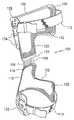
- FIG. 1is side elevational view of an embodiment of a knee brace having a posterior hinge device.
- FIG. 2is a front elevational view of the embodiment of FIG. 1 .
- FIG. 3is a rear elevational view of the embodiment of FIG. 1 .
- FIG. 4is side schematic elevational view of the embodiment of FIG. 1 having a sleeve placed thereover.
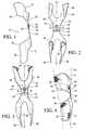
- FIG. 5is front elevational view of a precut and non-customized lower frame member of the embodiment of FIG. 1 .
- FIG. 6is a sectional view taken from FIG. 5 .
- FIG. 7is front elevational view of a precut and non-customized upper frame member of the embodiment of FIG. 1 .
- FIG. 8is rear schematic elevational view of a variation of the embodiment of FIG. 1 placed on a leg of a wearer.
- FIG. 9is a side schematic elevational view of the embodiment of FIG. 1 placed on a leg of a wearer in a bent configuration.
- FIG. 10is a front schematic elevational view of another embodiment of a knee brace having a posterior hinge device placed on a leg of a wearer.
- FIG. 11is a side schematic elevational view of the embodiment of FIG. 10 placed on a leg of a wearer in a bent configuration.
- FIG. 12is a perspective view of another embodiment of a knee brace having a posterior hinge device in a bent configuration.
- FIG. 13is a perspective view of the embodiment of FIG. 12 in a straight configuration.
- FIG. 14is a rear elevational view of the embodiment and configuration of FIG. 13 .
- FIG. 15is a side elevational view of the embodiment and configuration of FIG. 13 .
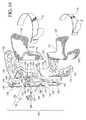
- FIG. 16is an exploded perspective view of the embodiment of FIG. 13 .
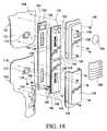
- FIG. 17is a sectional view of the hinge and bracket of FIG. 16 .
- FIG. 18is another sectional perspective view of the hinge and bracket of FIG. 17 .
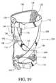
- FIG. 19is a perspective view of another embodiment of a knee brace having a posterior hinge device.
- Embodiments of the inventionare provided which are designed to stabilize a knee joint that has been weakened by injury or other infirmities.
- Embodiments of the inventionare particularly adapted for a human knee joint, and may be dimensioned to accommodate different types, shapes and sizes of human joints and appendages.
- the knee brace embodiments described hereinare configured to support and stabilize a knee joint, and to provide energy return to the knee so as to assist the return of the leg and knee to a straight configuration when the knee is bent.
- a resilient hinge deviceis generally provided which corresponds to the posterior of the knee so that it is flexed at generally the same location at which the knee is bent. Due to the resiliency of the hinge, the leg is urged into a generally straight configuration when the leg is bent.
- Lower and upper frame membersare provided for leg portions located lower and upper the knee, and are connected to one another with the hinge.
- the lower and upper frame membersposition the hinge relative to the knee, and further distribute loads placed on the knee to the upper and lower leg portions.
- the embodiments described hereinprovide different knee brace constructions to support and stabilize a knee joint with a posterior hinge device. These embodiments provide features which may be selectively used to replace corresponding features in any one of the other embodiments or variations described herein.
- the embodiments described hereinare divided into sections which are denoted by general anatomical terms for the human body. These terms include dividing the knee brace into anterior and posterior sections by an anterior-posterior plane.
- the anterior-posterior planegenerally corresponds to the coronal or frontal plane of a human leg.
- Each of the anterior and posterior sectionsis further divided about the center of the leg by a proximal-distal plane and a lateral-medial plane.
- any of the embodiments described hereinmay be adapted to include any of the components, such as straps, tightening devices and buckles, described in co-pending U.S. application Ser. No. 11/312,514 filed on Dec. 21, 2005 and incorporated herein by reference. Moreover, any of the components described herein may be constructed in the manner or from the materials described in co-pending U.S. application Ser. No. 11/312,514.
- the knee brace 10is configured for positioning on the posterior side of the leg, and has upper and lower frame members 12 , 14 .
- the first or lower frame member 12defines front or anterior, and rear or posterior surfaces, and includes a first end portion 24 , a central portion 22 , and a second end portion defined by first and second arms 26 , 28 branching from the central portion 22 .
- the lower frame member 12includes a hinge 16 that is located near the first end portion 24 .
- the hinge 16is formed from the lower frame member 12 and has a profile that is defined as an undulation or a peak that extends outwardly from the first member 12 and away from the posterior side of an intended leg. While only one undulation is shown in the exemplary views of FIGS. 1-3 , it will be understood that the hinge 16 may be defined by a plurality of undulations along the central portion 22 .
- the second or upper frame member 14has front and rear surfaces, and includes a first end portion 34 that is joined to the first end portion 24 of the first member 12 , a central portion 32 , and a second end portion defined by first and second arms 38 , 40 extending from the branch from the central portion 32 .
- the lower and upper frame members 12 , 14are connected at a joint 18 that permits the lower and upper frame members to be pivotably adjustable relative to one another.
- a suitable adjustment mechanism 20is provided which permits the adjustment of the lower and upper frame members relative to one another so as to provide varus or valgus adjustment for an intended wearer of the brace 10 .
- the adjustment mechanismmay be any type of device which permits selective securing of the lower and upper frame members relative to one another.
- the first and second arms of both the lower and upper frame members 12 , 14are provided to correspond to medial and lateral sides of the leg depending on which side of the leg the knee brace 10 is fitted for.
- the lower frame member 12 and the upper frame member 14each define a longitudinal, central axis A-A, B-B, respectively.
- Each of the first and second arms 26 , 28 of the lower frame member 12has a curved portion 30 that extends about the axis A-A and is intended to wrap about the leg so as to extend from the posterior side to at least a portion of the anterior side of an intended leg.
- the first and second arms 26 , 28may have greater curvature at a location closer to the first end portion 24 than at the opposed second end of the lower frame member 12 .
- the first and second arms 36 , 38 of the upper frame member 14also each has a curved portion 40 that extends about the axis B-B to wrap about the leg so as to extend from the posterior side to at least a portion of the anterior side of an intended leg.
- the lower and upper frame members 12 , 14may be adjusted relative to one another so that the axes A-A and B-B are not aligned. This would be desirable is there is need to provide varus or valgus adjustment for the intended wearer of the brace. This of course can be achieved by using the adjustment mechanism 20 that is used to secure the lower and upper frame members 12 , 14 to one another.
- Suitable indicia 46is provided on the rear surface of one of the lower and upper frame members 12 , 14 to indicate the orientation in which the frame members should be adjusted to obtain varus or valgus adjustment.
- Both the lower and upper frame members 12 , 14include a padding feature 42 , 44 that is located on the second surface of the lower and upper frame members 12 , 14 along regions of their respective first and second arms.
- the padding feature 42 , 44may comprise any one or combination of materials such as foam, textile, or any other suitable padding material known to those skilled in the art such as those used for spacers in U.S. application Ser. No. 11/312,514.
- the padding feature 42 , 44may include a frictional feature that maintains the lower and upper frame members 12 , 14 from rotating or shifting about a leg.
- the frictional featureis an apertured silicone coating that provides ventilation, as taught in U.S. application Ser. No. 11/312,514.
- Other suitable frictional featuresmay be employed that prevent the lower and upper frame members from rotating or shifting about a leg.
- FIG. 4exemplifies the brace 10 located on a leg having a lower leg portion 52 , knee portion 54 and upper leg portion 56 .
- the braceis illustrated as being located generally on the posterior side of the knee portion 54 , whereat the hinge 16 extends outwardly from posterior side of the knee portion 54 .
- the lower frame member 12is configured for securing to the lower leg portion 52 and the upper frame member 14 is configured for securing to upper leg portion 56 .
- a sleeve 58which covers the first surface of the brace 10 .
- the sleeve 58includes a knee portion 70 that is defined as an opening on the anterior side of the knee portion 54 of the leg.
- the first surfaces of the lower and upper frame members 12 , 14may be secured to an inside surface of the sleeve 58 , or in the alternative, the sleeve 58 may include pockets wherein portions of the brace may be inserted therein.
- Other meansmay be provided to secure the brace to the inside surface of the sleeve including hook and loop fasteners, stitching, adhesives, or snap fasteners.
- the sleeve 58may be constructed in a similar manner as in the sleeve embodiments taught by U.S. application Ser. No. 11/312,514.
- FIGS. 5-7show a precut version of a knee brace, wherein lower frame member 13 and upper frame member 15 are substantially flat with the hinge 17 being preformed and protruding from the remainder of the lower frame member 13 .
- the lower and upper frame members 13 , 15may be molded and trimmed to accommodate a wearer's leg so as to form the brace to the particular wearer.
- the precut yet non-customized lower and upper frame members 13 , 15may be provided in a kit with suitable buckles, fasteners such as rivets, straps and tightening devices so as to allow an orthotist or other medical professional to customize the brace by themselves according to the needs of the wearer.
- the lower frame member 13includes the first and second lower arms 27 , 29 which continue to the lower neck 23 having the hinge 17 , and the lower branch 25 having the first aperture 49 .
- the lower frame member 13also includes padding 43 that is positioned and precut to correspond to the first and second lower arms 27 , 29 .
- the upper flame memberincludes the first and second upper arms 37 , 39 which extend to the upper neck 33 and upper branch 35 having the second aperture 51 .
- Suitable padding 45is also provided so as to correspond to first and second upper arms 37 , 39 .
- the lower and upper frame members 13 , 15may be configured with suitable apertures, slots, grooves, protrusions, and rings to accommodate buckles, straps and tightening mechanisms of the type taught in U.S. application Ser. No. 11/312,514. Furthermore, the lower and upper frame members 13 , 15 may be preformed to include a perforated pattern of the types that are shown in connection with FIGS. 12-16 and U.S. application Ser. No. 11/312,514.
- the lower and upper frame membersare single-body entities comprising a resin impregnated carbon fiber composite system. Since the frame members are provided as kit, it is preferred that the resin is uncured.
- the lower and upper frame membersmay also be constructed from a variety of moldable materials such as TRIAX (abs/nylon blend), polypropylene, polyethylene, nylon, aramid or glass fiber prepeg with thermosetting or thermoplastic resins, and rigid foam from EVA, platezote or polyurethane.
- the frame members according to the knee brace described hereinmay be formed to be substantially rigid, or alternatively may be flexible.
- the frame membersare preferably structurally flexible so as to extend closely about the leg of the wearer, yet sufficiently strong to redistribute the weight on the knee to the legs of the wearer.
- any frame member constructionmay also be used that is consistent with the frame member construction taught in U.S. application Ser. No. 11/312,514.
- FIG. 8illustrates a variation of the brace located on a leg.
- the first arm 28is longer than the second 26 wherein the first arm 26 corresponds to a medial side of the lower leg portion 52 and the second arm 28 corresponds to a lateral side of the lower leg portion 52 .
- the first arm 26corresponds to a medial side of the lower leg portion 52
- the second arm 28corresponds to a lateral side of the lower leg portion 52 .
- the brace 10 of FIGS. 1-6is shown on a leg wherein the upper leg portion 56 bends at the knee portion 54 relative to the lower leg portion 52 .
- the hinge 16is flexed at generally the same location as the knee portion 54 is bent. Due to the resiliency of the hinge, the leg is urged into a generally straight configuration when the leg is bent.
- the hinge 16assists the wearer in controlling the movement of the leg and knee, and especially controls their motion so to return to the leg to a straight configuration, as exemplified in FIG. 4 .
- FIGS. 10 and 11show another embodiment of the knee brace wherein the first arm 60 of the lower frame member 59 generally curves along and about the axis A-A of the lower frame member and wraps about the anterior side of the lower leg 52 .
- the second arm 62 of the lower frame member 59only curves about the axis A-A so as to extend substantially transversely from the central portion 59 .
- the upper frame member 64only includes one arm that is defined by a central section 65 and a second end section 66 extending from the central section 65 .
- the second end section 66extends around an intended upper leg portion 56 to at least a part of the anterior side of the upper leg portion 56 .
- a hinge 68connects first end portions 63 , 67 of the lower and upper frame members 59 , 64 , respectively.
- the hinge 68is essentially a spring device, such as in a double torsion or spiral spring or springs, connecting the lower and upper frame members 59 , 64 .
- the lower frame member 59may be configured to have a hinge so as to resemble the hinge in the embodiment according to FIGS. 1-3 .
- the hingemay be separate from the lower and upper frame members 59 , 65 , or may be formed by a combination of both the first end portions 63 , 67 of the lower and upper frame members such that the lower and upper frame members run continuously with one another with the except of a formed hinge having at least one undulation.
- FIGS. 12-18exemplify another embodiment of a knee brace 100 according to the invention.
- upper and lower frame members 102 , 104are coupled by a hinge device 106 .
- the first or lower frame member 102defines front or anterior, and rear or posterior surfaces, and includes a first end portion 116 , a central portion 118 , and a second end portion defined by first and second arms 120 , 122 branching from the central portion 118 .
- the second or upper frame member 104has front or anterior, and rear or posterior surfaces, and includes a first end portion 124 , a central portion 125 , and a second end portion defined by first and second arms 126 , 128 that branch from the central portion 125 .
- the brace 100includes suitable padding 130 , 132 corresponding to the lower and upper frame members.
- the padding 130 , 132preferably includes a frictional feature 133 , such as a silicone coating.
- straps 110 , 112are provided which span the first and second sides of the lower and upper frame members which secure the brace onto the leg of the wearer. Taken together, the frictional feature 133 and the straps 110 , 112 maintain the brace 100 from rotating and migrating on a leg of the wearer.
- the brace 100has upper and lower brackets 136 , 138 which are secured to and combine with the lower and upper frame members 102 , 104 , respectively, to define channels therewith. As will be discussed more fully in connection with FIGS. 16-18 , these channels 136 , 138 receive portions of the hinge device 106 .
- the hinge device 106includes a cover 108 located between the upper and lower brackets 136 , 138 , and a locking mechanism 164 having a lock 170 with a cover 166 which allows for selective activation of the hinge device 106 .
- the lock 170preferably protrudes through and from the upper bracket 138 .
- the brackets 136 , 138have flanges 140 which are secured to the lower and upper frame members 102 , 104 so as to prevent interference with the portions of the hinge device 106 located in the channels.
- the hinge device 106restrains movement of the upper frame member 104 relative to the lower frame member 102 within a preferable range of 10°-30°.
- the bracemay be configured for any desirable range useful to the wearer of the brace.
- the bracemay be configured so that the hinge device provides resistance, as in the aforementioned embodiments, even when the hinge device 106 is not locked.
- This particular embodimentis useful for skiers since the brace reduces or eliminates the load of the skier off of the knee and the quadriceps when skiing.
- a skierWhen a skier is ready to go down a ski slope, he pushes the button on the locking mechanism and the brace locks the upper frame member relative to the lower frame member within a given range of angles. It follows that when the skier is finished with skiing, the locking mechanism is released and the upper frame member is able to move freely relative to the lower frame member thereby permitting the wearer a freedom of motion of approximately 0°-140°.
- Adjustable straps 110 , 112are secured to the first and second arms of the lower and upper frame members 102 , 104 for securing the brace 100 against the leg of a wearer. These straps 110 , 112 may be secured to the first and second arms by extending through slots (not shown) defined by the first and second arms. In other variations, the straps 110 , 112 may be secured to the lower and upper frame members with fasteners or other suitable securing means. The straps may be either elastic or substantially inelastic. Exemplary variations of the straps and means for securing the straps are found in U.S. application Ser. No. 11/312,514.
- the lower and upper frame members 102 , 104have a ventilated structure 134 defined by a plurality of apertures or slots.
- the ventilated structure 134provides a transfer of air through portions of the lower and upper frame members 102 , 104 , and greatly reduces the heat that may arise between the brace and a wearer's skin.
- Exemplary variations of the lower and upper frame members and their structuremay be adapted in any of the manners described in connection with the shells of U.S. application Ser. No. 11/312,514.
- the ventilated structurealso allows for the lower and upper frame members to be sized larger than other frame elements, such as the lower and upper frame members in the embodiment of FIG. 1 .
- the bracehas greater comfortability to a wearer of the brace. Because there is greater surface area, and particularly taken in combination with a frictional feature of the padding, there is less likelihood that the lower and upper frame members will rotate about a wearer's leg.
- the ventilated structuremay assume any one of numerous configurations that permit a transfer of air through and across the thickness of the lower and upper frame members between the first and second surfaces.
- the ventilated structurecomprises a plurality of elongate slots extending in parallel directions.
- the ventilated structuremay assume the configuration of large holes or any appropriate shape including but not limited to circles, rectangles, straight or curved lines.
- certain areas of the lower and upper frame membersmay have regions with greater ventilation than at other areas.
- the padding 130 , 132is secured on the second surfaces of the lower and upper frame members 102 , 104 , respectively.
- the padding 130 , 132cooperates with the ventilated structure 134 of the lower and upper frame members, and is preferably ventilated with a perforated structure 135 .
- the frictional feature 133 of the paddingis preferably a silicone composition that is coated on the anterior side of the perforated structure 135 without occluding the perforated structure.
- the padding 130 , 132includes an edging 131 which bounds the padding, which may be coated with the silicone composition.
- the posterior side of the paddingmay be coated with the silicone composition without occluding the perforated structure.
- the padding 130 , 132extends over nearly the entire second surface of the lower and upper frame members. In other variations, the padding may extend in only certain sections of the lower and upper frame members, as shown in connection with the embodiment of FIGS. 1-3 .
- the paddingmay have substantially the same structure as the padding feature 42 , 44 described above in reference to the embodiment of FIG. 1 , and further described in U.S. application Ser. No. 11/312,514.
- the paddingmay be secured to the lower and upper frame members in a variety of different manners readily understood by one skilled in the art. Such manners include using hook and loop fastening means, snaps or bonding with an adhesive.
- the hinge device 106comprises a hinge defined by lower and upper hinge elements 142 , 144 connected to one another with a pivotable joint 143 .
- the lower and upper hinge elements 142 , 144cooperate with a cantilever spring 156 that restrains movement of the lower and upper hinge elements 142 , 144 so that they are generally pivotable relative to each other thereby enabling them to pivot from a parallel and axially aligned position towards a direction away from the lower and upper frame members 102 , 104 .
- the lock 170is provided to permit the upper hinge element 144 to be selectively engaged with the cantilever spring 156 so as to restrain movement of the hinge elements 142 , 144 .
- the cover 108surrounds portions of the hinge device 106 that extend between the upper and lower brackets 136 , 138 .
- Both lower and upper hinge elements 142 , 144include elongate slots 151 , 152 wherein top and bottom springs 148 , 148 ′, and 149 . 149 ′ are located, respectively.
- the slots 151 , 152are generally longitudinal in nature and extend along the axis of the lower and upper hinge elements 142 , 144 .
- the upper hinge element 144also includes an opening 154 which is configured for receiving the lock 170 .
- the lock 170is arranged to be pressed through the opening 154 so to protrude towards the posterior side of the upper frame member 104 .
- the lock 170is not in a locked position, it is arranged to protrude from the opening 139 of the upper bracket 138 , and the lower and upper hinge elements 142 , 144 can slide freely relative to the cantilever spring 156 .
- the lock 170can be any lockable and releasable device that is configured be pressed so as to engage the cantilever spring 156 , and released so as to disengage the cantilever spring 156 .
- the lock 170may be spring biased, and have detents and catches which enable it to retain its position when pressed but release when it is pressed again.
- the lower and upper hinge elements 142 , 144include longitudinal grooves 146 , 150 which are located along the edges of the lower and upper hinge elements 142 , 144 . These grooves 146 , 150 are configured for engaging ribs 167 and 168 located along the inner walls of the lower and upper brackets 136 , 138 . The groove and rib combination restrains movement of the lower and upper hinge elements so that they are constrained to travel linearly relative to the lower and upper frame members 102 , 104 .
- the cantilever spring 156is arranged for cooperating and selectively locking with the lock 170 .
- the cantilever spring 156includes lower and upper longitudinal slots 158 , 160 that correspond with the elongate slots 151 , 152 of the lower and upper hinge elements 142 , 144 .
- the cantilever spring 156also includes an opening 162 that is configured for permitting the lock 170 to engage therewith so as to effectively lock the cantilever spring 156 with the upper hinge element 144 .
- the cantilever spring 156is secured to the lower frame member 102 via fasteners 180 which extend through lower apertures 176 and engage with nubs 178 extending from the lower frame member 102 .
- fasteners 180which extend through lower apertures 176 and engage with nubs 178 extending from the lower frame member 102 .
- the lower and upper frame members 102 , 104each include protrusions 172 , 174 , respectively, that are arranged to extend through the slots 158 , 160 of the cantilever spring 156 , and the slots 151 , 152 of the lower and upper hinge elements 142 , 144 .
- the protrusions 172 , 174are positioned within the slots 151 , 152 , between springs 148 , 148 ′ and 149 , 149 ′, respectively.
- the springs 148 , 148 ′ and 149 , 149 ′provide some energy return and assist in placing the hinge device 106 in a neutral position, resulting in the hinge device being substantially straight.
- the cantilever spring 156is able to slide relative to the protrusion 174 , when the cantilever spring 156 is not engaged with the locking mechanism 170 .
- the lower and upper hinge elements 142 , 144are able to slide relative to the lower and upper brackets 136 , 138 , due to the slots 151 , 152 , when the locking mechanism 170 does not engage the cantilever spring 156 .
- the protrusions 172 , 174limit the travel of the cantilever spring 156 , and lower and upper hinge elements 142 , 144 , thereby limiting the rotation of the upper frame member 104 relative to the lower frame member 102 .
- the locking mechanism 170engages the cantilever spring 156 , the lower and upper frame members 102 , 104 are only able to pivot relative to one another from a range of 10°-30°.
- the cantilever springmay be modified so as to permit flexion at a plurality of angles that may be desired.
- the cantilever spring 156may define different profiles from the flat profile shown herein, and is preferably constructed from a resin impregnated carbon fiber composite system that provides some flexure.
- the cantilever springmay also be constructed from a variety of materials providing some flexure such as TRIAX (abs/nylon blend), polypropylene, polyethylene, nylon, aramid or glass fiber prepeg with thermosetting or thermoplastic resins, and combinations thereof.
- the cantilever springmay be constructed with memory shape alloys, or have memory shape alloy wires embedded in a polymeric or composite system, that permit repeated flexure of the hinge device.
- the cantilever springmay define varying degrees of stiffness, such that the central portion is generally more flexible than at end portions, or in the alternative one end portion may have greater flexibility than the other end portion.
- FIG. 19another embodiment of the knee brace 200 having a similar construction to the embodiment of FIGS. 14-18 or any other of the embodiments herein, may include force straps 202 , 204 which cross below the knee of the intended wearer, and apply a force along the side of the wearer's knee.
- the force strapsmay be adjusted to provide differing degrees of force against the knee.
- the force strapsmay be configured to cross above the knee, or along one of the sides of the knee.
- the force strapsmay be configured in any manner consistent with the force straps described in U.S. application Ser. No. 11/312,514 for correcting alignment of a knee, or providing stabilization of a knee due to impact.
- sensing systems for monitoring and controlling gait dynamicsmay be used for the purposes of alignment, safety, and other needs of the wearer.
- Exemplary sensing systems that may be used with any of the embodiments hereinare found in co-pending U.S. application Ser. Nos. 11/184,011 and 11/430,076 incorporated herein by reference.
- mechanical and fluid based devicesmay be used in substitution or in combination with the hinge devices to control braking of the hinge devices.
- An exemplary method for controlling braking of the kneeis found in co-pending U.S. application Ser. No. 11/417,460 incorporated herein by reference.
Landscapes
- Health & Medical Sciences (AREA)
- Nursing (AREA)
- Orthopedic Medicine & Surgery (AREA)
- Engineering & Computer Science (AREA)
- Biomedical Technology (AREA)
- Heart & Thoracic Surgery (AREA)
- Vascular Medicine (AREA)
- Life Sciences & Earth Sciences (AREA)
- Animal Behavior & Ethology (AREA)
- General Health & Medical Sciences (AREA)
- Public Health (AREA)
- Veterinary Medicine (AREA)
- Orthopedics, Nursing, And Contraception (AREA)
Abstract
Description
Claims (16)
Priority Applications (2)
| Application Number | Priority Date | Filing Date | Title |
|---|---|---|---|
| US11/546,244US7704218B2 (en) | 2005-10-12 | 2006-10-12 | Knee brace |
| US12/721,634US8216166B2 (en) | 2005-10-12 | 2010-03-11 | Knee brace |
Applications Claiming Priority (2)
| Application Number | Priority Date | Filing Date | Title |
|---|---|---|---|
| US72530605P | 2005-10-12 | 2005-10-12 | |
| US11/546,244US7704218B2 (en) | 2005-10-12 | 2006-10-12 | Knee brace |
Related Child Applications (1)
| Application Number | Title | Priority Date | Filing Date |
|---|---|---|---|
| US12/721,634ContinuationUS8216166B2 (en) | 2005-10-12 | 2010-03-11 | Knee brace |
Publications (2)
| Publication Number | Publication Date |
|---|---|
| US20070083136A1 US20070083136A1 (en) | 2007-04-12 |
| US7704218B2true US7704218B2 (en) | 2010-04-27 |
Family
ID=37963109
Family Applications (2)
| Application Number | Title | Priority Date | Filing Date |
|---|---|---|---|
| US11/546,244Active2027-05-29US7704218B2 (en) | 2005-10-12 | 2006-10-12 | Knee brace |
| US12/721,634Expired - Fee RelatedUS8216166B2 (en) | 2005-10-12 | 2010-03-11 | Knee brace |
Family Applications After (1)
| Application Number | Title | Priority Date | Filing Date |
|---|---|---|---|
| US12/721,634Expired - Fee RelatedUS8216166B2 (en) | 2005-10-12 | 2010-03-11 | Knee brace |
Country Status (5)
| Country | Link |
|---|---|
| US (2) | US7704218B2 (en) |
| EP (1) | EP1945154B1 (en) |
| CN (1) | CN101282698A (en) |
| CA (1) | CA2624989C (en) |
| WO (1) | WO2007047424A2 (en) |
Cited By (34)
| Publication number | Priority date | Publication date | Assignee | Title |
|---|---|---|---|---|
| US20040064195A1 (en)* | 2002-07-15 | 2004-04-01 | Hugh Herr | Variable-mechanical-impedance artificial legs |
| US20100063433A1 (en)* | 2008-09-05 | 2010-03-11 | Linares Medical Devices, Llc | Temporary splint assembly with semi-rigid wrap around supports in combination with intermediately positioned joint cast |
| US20100114329A1 (en)* | 2005-03-31 | 2010-05-06 | Iwalk, Inc. | Hybrid terrain-adaptive lower-extremity systems |
| US20100113980A1 (en)* | 2008-09-04 | 2010-05-06 | Iwalk, Inc. | Hybrid Terrain-Adaptive Lower-Extremity Systems |
| US20100241242A1 (en)* | 2005-03-31 | 2010-09-23 | Massachusetts Institute Of Technology | Artificial Joints Using Agonist-Antagonist Actuators |
| US20100324699A1 (en)* | 2005-03-31 | 2010-12-23 | Massachusetts Institute Of Technology | Model-Based Neuromechanical Controller for a Robotic Leg |
| US20110040216A1 (en)* | 2005-03-31 | 2011-02-17 | Massachusetts Institute Of Technology | Exoskeletons for running and walking |
| US20110082566A1 (en)* | 2008-09-04 | 2011-04-07 | Herr Hugh M | Implementing a stand-up sequence using a lower-extremity prosthesis or orthosis |
| US20120010548A1 (en)* | 2010-07-08 | 2012-01-12 | Scholtes Sara A | Knee Brace to Limit Rotation Between the Femur and Tibia |
| US8287477B1 (en) | 2003-09-25 | 2012-10-16 | Massachusetts Institute Of Technology | Active ankle foot orthosis |
| US8500823B2 (en) | 2005-03-31 | 2013-08-06 | Massachusetts Institute Of Technology | Powered artificial knee with agonist-antagonist actuation |
| US8512415B2 (en) | 2005-03-31 | 2013-08-20 | Massachusetts Institute Of Technology | Powered ankle-foot prothesis |
| US8734528B2 (en) | 2005-03-31 | 2014-05-27 | Massachusetts Institute Of Technology | Artificial ankle-foot system with spring, variable-damping, and series-elastic actuator components |
| US9032635B2 (en) | 2011-12-15 | 2015-05-19 | Massachusetts Institute Of Technology | Physiological measurement device or wearable device interface simulator and method of use |
| US9060883B2 (en) | 2011-03-11 | 2015-06-23 | Iwalk, Inc. | Biomimetic joint actuators |
| KR101543191B1 (en) | 2014-10-22 | 2015-08-07 | 박종완 | Assistant apparatus for sitting works |
| US9221177B2 (en) | 2012-04-18 | 2015-12-29 | Massachusetts Institute Of Technology | Neuromuscular model-based sensing and control paradigm for a robotic leg |
| US9333097B2 (en) | 2005-03-31 | 2016-05-10 | Massachusetts Institute Of Technology | Artificial human limbs and joints employing actuators, springs, and variable-damper elements |
| US9687377B2 (en) | 2011-01-21 | 2017-06-27 | Bionx Medical Technologies, Inc. | Terrain adaptive powered joint orthosis |
| US9693883B2 (en) | 2010-04-05 | 2017-07-04 | Bionx Medical Technologies, Inc. | Controlling power in a prosthesis or orthosis based on predicted walking speed or surrogate for same |
| US9724226B2 (en) | 2010-07-13 | 2017-08-08 | Breg, Inc. | Orthopedic brace having a support member and an adapted pad |
| US9737419B2 (en) | 2011-11-02 | 2017-08-22 | Bionx Medical Technologies, Inc. | Biomimetic transfemoral prosthesis |
| US9839552B2 (en) | 2011-01-10 | 2017-12-12 | Bionx Medical Technologies, Inc. | Powered joint orthosis |
| US10117769B2 (en) | 2016-08-31 | 2018-11-06 | Jay C. Humphrey | Orthopedic knee brace |
| USD846130S1 (en) | 2018-01-31 | 2019-04-16 | Ortho Systems | Knee brace |
| US10307272B2 (en) | 2005-03-31 | 2019-06-04 | Massachusetts Institute Of Technology | Method for using a model-based controller for a robotic leg |
| US10531965B2 (en) | 2012-06-12 | 2020-01-14 | Bionx Medical Technologies, Inc. | Prosthetic, orthotic or exoskeleton device |
| US10537449B2 (en) | 2011-01-12 | 2020-01-21 | Bionx Medical Technologies, Inc. | Controlling powered human augmentation devices |
| US20210106449A1 (en)* | 2018-03-27 | 2021-04-15 | Sean C. Norton | Splint device |
| US11278433B2 (en) | 2005-03-31 | 2022-03-22 | Massachusetts Institute Of Technology | Powered ankle-foot prosthesis |
| US20230069860A1 (en)* | 2021-09-09 | 2023-03-09 | Stephen Eugene Juaire | Apparatus, system, and method for at least one of icing, heating, and compressing a user's body part |
| US20230233379A1 (en)* | 2021-09-09 | 2023-07-27 | Stephen Eugene Juaire | Apparatus, system, and method for at least one of icing, heating, and compressing a user's body part |
| US11918500B1 (en) | 2020-03-31 | 2024-03-05 | Preferred Prescription, Inc. | Hinged knee brace with double upper strap arrangement |
| US12121463B1 (en) | 2020-02-13 | 2024-10-22 | Preferred Prescription, Inc. | Knee/elbow brace |
Families Citing this family (45)
| Publication number | Priority date | Publication date | Assignee | Title |
|---|---|---|---|---|
| US9220622B2 (en) | 2004-12-22 | 2015-12-29 | Ossur Hf | Orthopedic device |
| US8585623B2 (en) | 2004-12-22 | 2013-11-19 | Ossur Hf | Orthopedic device |
| US7597675B2 (en) | 2004-12-22 | 2009-10-06 | össur hf | Knee brace and method for securing the same |
| US8425441B2 (en) | 2004-12-22 | 2013-04-23 | Ossur Hf | Spacer element for use in an orthopedic or prosthetic device |
| US8216170B2 (en) | 2004-12-22 | 2012-07-10 | Ossur Hf | Orthopedic device |
| US8231560B2 (en) | 2004-12-22 | 2012-07-31 | Ossur Hf | Orthotic device and method for securing the same |
| ATE519389T1 (en)* | 2007-02-27 | 2011-08-15 | Gruppo Decortex S R L | GARMENT WITH SILICONE WELDING BAND AND PRODUCTION METHOD THEREOF |
| US10842653B2 (en) | 2007-09-19 | 2020-11-24 | Ability Dynamics, Llc | Vacuum system for a prosthetic foot |
| US8167829B2 (en)* | 2007-10-19 | 2012-05-01 | Bellacure Inc. | Orthotic apparatus |
| US7927299B2 (en)* | 2008-01-31 | 2011-04-19 | Krause David A | Knee brace |
| CN102026595B (en)* | 2008-05-14 | 2013-11-20 | 奥苏尔公司 | Leg support |
| CN101357090B (en)* | 2008-09-01 | 2011-01-05 | 朱怀琪 | Knee-joint hyperextension-prevention rehabilitation rectifier |
| DE102009000374A1 (en)† | 2009-01-22 | 2010-07-29 | Karsten Keuchen | Thoracic bandage with at least one pad |
| WO2011073803A2 (en)* | 2009-12-17 | 2011-06-23 | Ossur Hf | Orthopedic device |
| CN102151186B (en)* | 2011-04-14 | 2013-04-10 | 万得医疗器材用品(深圳)有限公司 | Orthopedic protection support for treating osteoarthritis |
| US8876743B2 (en)* | 2011-04-20 | 2014-11-04 | Vivonics, Inc. | Conformable material for an orthotic device and method of making same |
| CN102429753B (en)* | 2011-09-07 | 2013-01-30 | 上海电机学院 | Knee assist device and method of use thereof |
| US9925082B2 (en) | 2012-03-20 | 2018-03-27 | Ossur Hf | Orthopedic device |
| EP2919603B1 (en) | 2012-11-13 | 2016-09-21 | Össur HF | Fastener member for affixation to a structure in an orthopedic device and method for securing the same |
| CN105228564B (en) | 2013-01-07 | 2017-11-14 | 奥索有限责任公司 | Orthopedic device and fixation method thereof |
| EP2950758B1 (en) | 2013-01-31 | 2020-11-18 | Össur HF | Progressive force strap assembly for use with an orthopedic device |
| US9375341B2 (en) | 2013-01-31 | 2016-06-28 | Ossur Hf | Orthopedic device having detachable components for treatment stages and method for using the same |
| EP2983627B1 (en) | 2013-04-08 | 2018-12-12 | Ossur hf | Strap attachment system for orthopedic device |
| US20140329649A1 (en)* | 2013-05-06 | 2014-11-06 | Michael Boutros | Rehabilitation Flexor |
| WO2015130855A1 (en)* | 2014-02-25 | 2015-09-03 | Jumpsport, Inc. | Knee and joint rehabilitation exercise device |
| DE102014019715A1 (en)* | 2014-12-23 | 2016-06-23 | Albrecht Gmbh | Orthosis with inclination adjustment device |
| WO2016112110A1 (en) | 2015-01-06 | 2016-07-14 | Ossur Iceland Ehf | Orthopedic device for treating osteoarthritis of the knee |
| US10188539B2 (en) | 2015-10-05 | 2019-01-29 | SpringLoaded Technology Incorporated | Stabilizing system for a knee brace |
| WO2017176680A1 (en) | 2016-04-04 | 2017-10-12 | Ossur Iceland Ehf | Orthopedic device |
| DE202016008233U1 (en)* | 2016-05-03 | 2017-05-05 | Oped Ag | Orthosis for stabilization of a body joint and modular system for forming an orthosis |
| DE102016108183A1 (en)* | 2016-05-03 | 2017-11-09 | Oped Ag | Orthosis for the stabilization of a body joint |
| US11850175B2 (en) | 2016-06-06 | 2023-12-26 | Ossur Iceland Ehf | Orthopedic device, strap system and method for securing the same |
| US11253384B2 (en) | 2016-06-06 | 2022-02-22 | Ossur Iceland Ehf | Orthopedic device, strap system and method for securing the same |
| USD835289S1 (en) | 2016-11-08 | 2018-12-04 | Ossur Iceland Ehf | Orthopedic device |
| USD813089S1 (en) | 2016-11-08 | 2018-03-20 | Ossur Iceland Ehf | D-ring |
| AU2018206399B2 (en) | 2017-01-06 | 2020-01-02 | Djo, Llc | Orthosis, related components and methods of use |
| CN111278390B (en)* | 2017-10-06 | 2022-12-20 | 奥索冰岛有限公司 | Orthopedic device for knee unloading |
| CA3079503A1 (en)* | 2017-11-07 | 2019-05-16 | Djo, Llc | Brace having integrated remote patient monitoring technology and method of using same |
| WO2019241201A1 (en)* | 2018-06-11 | 2019-12-19 | Ossur Iceland Ehf | Multi-component frame for use in an orthopedic device |
| USD882803S1 (en) | 2018-10-08 | 2020-04-28 | Ossur Iceland Ehf | Orthopedic shell |
| USD888258S1 (en) | 2018-10-08 | 2020-06-23 | Ossur Iceland Ehf | Connector assembly |
| USD908458S1 (en) | 2018-10-08 | 2021-01-26 | Ossur Iceland Ehf | Hinge cover |
| CN112716718A (en)* | 2020-12-24 | 2021-04-30 | 喻维清 | Nursing equipment capable of automatically adjusting supporting force according to patient |
| US11872150B2 (en) | 2020-12-28 | 2024-01-16 | Ossur Iceland Ehf | Sleeve and method for use with orthopedic device |
| US20250281311A1 (en)* | 2024-03-07 | 2025-09-11 | Icarus Medical, LLC | Mechanism and method for donning orthotic device to prosthesis, limb, or joint |
Citations (81)
| Publication number | Priority date | Publication date | Assignee | Title |
|---|---|---|---|---|
| US161323A (en) | 1875-03-30 | Improvement in fracture-splints | ||
| US183376A (en) | 1876-10-17 | Improvement in apparatus for contracted joints | ||
| US552143A (en) | 1895-12-31 | Adjustable splint | ||
| US646659A (en) | 1899-06-16 | 1900-04-03 | John F Gail | Spring bed-bottom. |
| US1446230A (en) | 1921-03-31 | 1923-02-20 | Welter Johannes Franciscus | Walking apparatus for the lame |
| CH170152A (en) | 1932-04-14 | 1934-06-30 | Canouil Andre Henri Louis Vict | Drill chuck. |
| US3304937A (en) | 1964-07-24 | 1967-02-21 | Jr George R Callender | Derotation brace for tibia deformities |
| US3526222A (en) | 1968-05-24 | 1970-09-01 | Robert E Dreibelbis | Pediatric restraining apparatus |
| US3799159A (en) | 1971-10-28 | 1974-03-26 | Us Health Education & Welfare | Hydraulic flexion control device |
| US3831467A (en) | 1973-03-16 | 1974-08-27 | R Moore | Knee brace |
| US3928872A (en) | 1974-09-18 | 1975-12-30 | Albert F Johnson | Leg support device for skiing |
| US3933154A (en) | 1974-01-15 | 1976-01-20 | Cabansag Edwin M | Immobilizer device |
| US3935858A (en) | 1975-01-13 | 1976-02-03 | Orthopedic Equipment Company, Inc. | Knee immobilizer |
| US3958567A (en) | 1975-04-29 | 1976-05-25 | Callender Jr George R | Derotation brace for tibia deformities |
| US4041940A (en) | 1975-11-05 | 1977-08-16 | Frankel S Arthur | Contoured knee immobilizer |
| US4050455A (en) | 1976-07-26 | 1977-09-27 | The Raymond Lee Organization, Inc. | Foot and leg brace |
| US4090508A (en) | 1977-03-15 | 1978-05-23 | Medical Specialties, Incorporated | Orthopedic knee brace |
| US4111194A (en) | 1976-12-27 | 1978-09-05 | Rollin Webb Cox | Posterior knee immobilizing brace |
| US4130115A (en) | 1977-05-02 | 1978-12-19 | Taylor Glenn N | Brace hinge |
| US4198964A (en) | 1979-01-11 | 1980-04-22 | Zimmer Usa, Inc. | Acromioclavicular brace |
| US4275716A (en) | 1979-09-24 | 1981-06-30 | Scott Jr Linzy | Knee brace |
| US4388920A (en) | 1981-10-26 | 1983-06-21 | Professional Medical Products, Inc. | Variable position knee immobilizer |
| US4407276A (en) | 1981-01-22 | 1983-10-04 | Medical Designs, Inc. | Brace for articulated limbs |
| US4408600A (en) | 1980-05-02 | 1983-10-11 | Davis Edward P | Leg aid device and method |
| DE3245471A1 (en) | 1982-08-24 | 1984-03-08 | Erwin 8000 München Keuschnigg | Device for relieving the stress on leg muscles, in particular in skiing |
| US4450832A (en) | 1982-08-25 | 1984-05-29 | Waddell Thomas P | Body weight support system |
| US4489718A (en) | 1983-03-08 | 1984-12-25 | Medical Designs, Inc. | Knee brace hinge |
| US4522199A (en) | 1983-08-11 | 1985-06-11 | Thomas P. Waddell | Body weight support system |
| DE3520939A1 (en) | 1985-06-12 | 1986-12-18 | Sanitätshaus Heinz Pfau GmbH & Co KG, 1000 Berlin | Knee-guiding arrangement for correction of defective positions of the knee-joint |
| WO1987006820A1 (en) | 1986-05-13 | 1987-11-19 | Gunter Zaltenbach | Knee support device, especially for skiers |
| US4776326A (en) | 1985-07-09 | 1988-10-11 | Protectair Ltd. | Modular lower limb bracing system |
| US4796610A (en) | 1987-07-02 | 1989-01-10 | Donjoy, Inc. | Lateral impact knee guard and medial collateral ligament knee brace |
| US4844326A (en) | 1987-10-08 | 1989-07-04 | Mazda Motor Corporation | Method of and system for assembling vehicle bodies |
| US4848326A (en) | 1988-06-20 | 1989-07-18 | Robert Lonardo | Knee contracture correction device |
| US4981132A (en) | 1990-04-30 | 1991-01-01 | Andrew Chong | Orthosis for the treatment of tibial torsion in children |
| US4982732A (en) | 1990-02-06 | 1991-01-08 | Orthopedic Technology, Inc. | Orthopedic rehabilitation knee brace |
| US5007415A (en) | 1989-08-04 | 1991-04-16 | John E. Garber | Joint brace |
| US5088479A (en) | 1990-04-26 | 1992-02-18 | Detoro William W | Ankle and foot orthosis |
| US5116296A (en) | 1991-04-26 | 1992-05-26 | Medmetric Corporation | Isometric leg muscle ergometer |
| US5230700A (en) | 1989-04-28 | 1993-07-27 | Charles Humbert | Orthopedic apparatus for persons handicapped in one leg |
| WO1993015251A1 (en) | 1992-02-03 | 1993-08-05 | Fiberweb North America, Inc. | Elastic nonwoven webs and method of making same |
| US5261949A (en) | 1989-06-29 | 1993-11-16 | Sintermetallwerk Krebsoge Gmbh | Method of producing an atomized liquid to be conveyed in a stream of carrier gas and apparatus for implementing the method |
| US5267949A (en) | 1992-03-25 | 1993-12-07 | Manuel De La Torre | Positioning device for a lower extremity |
| US5269322A (en) | 1992-11-09 | 1993-12-14 | Edward Mandel | Lower back and spinal stress reducer apparatus |
| US5277698A (en) | 1991-05-08 | 1994-01-11 | Generation Ii Orthotics, Inc. | Knee bracing method |
| US5385534A (en) | 1993-07-09 | 1995-01-31 | Smith & Nephew Donjoy Inc. | Splint assembled from a flat stackable kit |
| US5387185A (en) | 1993-11-08 | 1995-02-07 | Aircast, Incorporated | Knee immobilizer splint |
| US5401235A (en) | 1992-06-03 | 1995-03-28 | Devens; Mark F. | Dynamic variable torque long bone torsion reducer |
| US5472409A (en)* | 1994-09-23 | 1995-12-05 | Hoy; David J. | Adjustable brace |
| US5486157A (en) | 1994-02-03 | 1996-01-23 | Dibenedetto; Anthony | Dynamic multi-angular ankle and foot orthosis device |
| US5545127A (en) | 1995-04-24 | 1996-08-13 | Detoro; William | Laterally adjustable ankle and foot orthosis |
| US5554104A (en) | 1992-12-18 | 1996-09-10 | Royce Medical Company | Custom formable knee brace |
| US5571206A (en) | 1994-05-16 | 1996-11-05 | Restorative Care Of America Incorporated | Leg amputee orthosis |
| US5593383A (en) | 1995-03-20 | 1997-01-14 | Detoro; William | Securing apparatus for an ankle and foot orthosis |
| US5732411A (en) | 1996-04-04 | 1998-03-31 | Trace Athletic Corporation | Adjustable guard for the lower leg and shin |
| US5788658A (en) | 1997-01-31 | 1998-08-04 | Islava; Steven T. | Field adjustable extrication collar |
| US5823931A (en)* | 1996-02-21 | 1998-10-20 | Bodyworks Healthcare Limited | Knee brace |
| US5908398A (en) | 1998-01-27 | 1999-06-01 | Detoro; William W. | Ajustable ankle and foot orthosis brace |
| USD429816S (en) | 1999-05-10 | 2000-08-22 | Cramer Products, Inc. | Articulated splint |
| US6302858B1 (en) | 2000-10-26 | 2001-10-16 | Anatomical Concepts, Inc. | Compound adjustable ankle foot orthosis brace |
| US6350246B1 (en) | 2000-02-23 | 2002-02-26 | Anatomical Concepts, Inc. | Ankle and foot therapeutic device |
| US6377178B1 (en) | 2000-06-20 | 2002-04-23 | William DeToro | Therapeutic ankle & foot apparatus having a contact sensor mechanism |
| US6383156B1 (en) | 1999-09-27 | 2002-05-07 | Dj Orthopedics, Llc | Orthopaedic brace having a range of motion hinge with an adjustable-length strut |
| US20020072695A1 (en) | 2000-12-12 | 2002-06-13 | Doty Del Ray | Orthopedic brace having length-adjustable supports |
| US6464659B1 (en) | 2001-06-18 | 2002-10-15 | Anatomical Concepts, Inc. | Pressure relief insert for therapeutic foot enclosures |
| US6471664B1 (en) | 2000-03-15 | 2002-10-29 | Becker Orthopedic Appliance Company | Knee joint and method |
| US6508281B1 (en)* | 2001-07-19 | 2003-01-21 | Tian Wang Wang | Adjustable and extendible platform for working table |
| US6524110B1 (en) | 1999-07-03 | 2003-02-25 | Owen Eastwood | Body weight supports and teaching aid |
| US6540703B1 (en) | 2000-11-20 | 2003-04-01 | Max Lerman | Post-operative hip abduction orthosis |
| US20030093018A1 (en) | 2000-02-10 | 2003-05-15 | Erich Albrecht | Orthesis comprising a flexion and an extension stop that can be adjusted by means of rail pivoting movements |
| US6592539B1 (en) | 1999-03-01 | 2003-07-15 | Ossur Hf | Orthotic or prosthetic sleeve formed of elasticized fabric sections having different elastic stiffness |
| US6719713B2 (en) | 2002-03-14 | 2004-04-13 | Breg, Inc. | Strap attachment assembly for an orthopedic brace |
| US6746248B2 (en) | 1999-07-03 | 2004-06-08 | Owen Eastwood | Body weight supports and teaching aid |
| USD496464S1 (en) | 2003-09-29 | 2004-09-21 | Royce Medical Company | Adjustable knee brace pivot assembly |
| US20050101895A1 (en) | 2003-11-12 | 2005-05-12 | Patel Amit V. | Injury immobilization device |
| US20050234374A1 (en) | 2004-04-20 | 2005-10-20 | Grim Tracy E | Splint or support with quick location technique |
| US7011641B1 (en) | 2003-10-29 | 2006-03-14 | Anatomical Concepts, Inc. | Knee brace immobilizer |
| US20060058893A1 (en) | 2004-05-28 | 2006-03-16 | Clausen Arinbjorn V | Method of measuring the performance of a prosthetic foot |
| US20060197051A1 (en) | 2003-05-02 | 2006-09-07 | Henry Hsu | Magnetorheological fluid compositions and prosthetic knees utilizing same |
| US20060206215A1 (en) | 2005-02-02 | 2006-09-14 | Clausen Arinbjorn V | Sensing systems and methods for monitoring gait dynamics |
| US20070232972A1 (en) | 2006-03-30 | 2007-10-04 | Kelvin Martinez | Agachaflex |
Family Cites Families (10)
| Publication number | Priority date | Publication date | Assignee | Title |
|---|---|---|---|---|
| US4854308A (en)* | 1986-12-29 | 1989-08-08 | Drillio Robert C | Knee orthosis having offset within hinges and anti-rotation straps |
| CN2173603Y (en) | 1993-11-09 | 1994-08-10 | 桑名昌 | Knee joint injury fixing walking aid |
| US5496157A (en)* | 1994-12-21 | 1996-03-05 | Carrier Corporation | Reverse rotation prevention for scroll compressors |
| US5873847A (en) | 1996-11-14 | 1999-02-23 | Lenjoy Engineering, Inc. | Articulated splints and goniometric hinge for the same |
| EP0917363A1 (en)* | 1997-11-17 | 1999-05-19 | STMicroelectronics S.r.l. | Motion estimator algorithm and system's architecture |
| US6793638B1 (en)* | 2002-10-07 | 2004-09-21 | Anatomical Concepts, Inc. | Leg stabilization and alignment device |
| US7112181B1 (en)* | 2003-04-07 | 2006-09-26 | Anatomical Concepts, Inc. | Tri-planar orthosis |
| US7713225B2 (en) | 2004-12-22 | 2010-05-11 | Ossur Hf | Knee brace and method for securing the same |
| US7682322B2 (en)* | 2005-02-15 | 2010-03-23 | Engelman Ian K | Articulated orthosis providing lift support |
| US7662119B2 (en)* | 2008-07-21 | 2010-02-16 | Anatomical Concepts, Inc. | Multiple function ratcheting orthotic device |
- 2006
- 2006-10-12WOPCT/US2006/040052patent/WO2007047424A2/enactiveApplication Filing
- 2006-10-12CNCNA2006800375063Apatent/CN101282698A/enactivePending
- 2006-10-12CACA2624989Apatent/CA2624989C/ennot_activeExpired - Fee Related
- 2006-10-12EPEP06816860.8Apatent/EP1945154B1/ennot_activeNot-in-force
- 2006-10-12USUS11/546,244patent/US7704218B2/enactiveActive
- 2010
- 2010-03-11USUS12/721,634patent/US8216166B2/ennot_activeExpired - Fee Related
Patent Citations (87)
| Publication number | Priority date | Publication date | Assignee | Title |
|---|---|---|---|---|
| US183376A (en) | 1876-10-17 | Improvement in apparatus for contracted joints | ||
| US552143A (en) | 1895-12-31 | Adjustable splint | ||
| US161323A (en) | 1875-03-30 | Improvement in fracture-splints | ||
| US646659A (en) | 1899-06-16 | 1900-04-03 | John F Gail | Spring bed-bottom. |
| US1446230A (en) | 1921-03-31 | 1923-02-20 | Welter Johannes Franciscus | Walking apparatus for the lame |
| CH170152A (en) | 1932-04-14 | 1934-06-30 | Canouil Andre Henri Louis Vict | Drill chuck. |
| US3304937A (en) | 1964-07-24 | 1967-02-21 | Jr George R Callender | Derotation brace for tibia deformities |
| US3526222A (en) | 1968-05-24 | 1970-09-01 | Robert E Dreibelbis | Pediatric restraining apparatus |
| US3799159A (en) | 1971-10-28 | 1974-03-26 | Us Health Education & Welfare | Hydraulic flexion control device |
| US3831467A (en) | 1973-03-16 | 1974-08-27 | R Moore | Knee brace |
| US3933154A (en) | 1974-01-15 | 1976-01-20 | Cabansag Edwin M | Immobilizer device |
| US3928872A (en) | 1974-09-18 | 1975-12-30 | Albert F Johnson | Leg support device for skiing |
| US3935858A (en) | 1975-01-13 | 1976-02-03 | Orthopedic Equipment Company, Inc. | Knee immobilizer |
| US3958567A (en) | 1975-04-29 | 1976-05-25 | Callender Jr George R | Derotation brace for tibia deformities |
| US4041940A (en) | 1975-11-05 | 1977-08-16 | Frankel S Arthur | Contoured knee immobilizer |
| US4050455A (en) | 1976-07-26 | 1977-09-27 | The Raymond Lee Organization, Inc. | Foot and leg brace |
| US4111194A (en) | 1976-12-27 | 1978-09-05 | Rollin Webb Cox | Posterior knee immobilizing brace |
| US4090508A (en) | 1977-03-15 | 1978-05-23 | Medical Specialties, Incorporated | Orthopedic knee brace |
| US4130115A (en) | 1977-05-02 | 1978-12-19 | Taylor Glenn N | Brace hinge |
| US4198964A (en) | 1979-01-11 | 1980-04-22 | Zimmer Usa, Inc. | Acromioclavicular brace |
| US4275716A (en) | 1979-09-24 | 1981-06-30 | Scott Jr Linzy | Knee brace |
| US4408600A (en) | 1980-05-02 | 1983-10-11 | Davis Edward P | Leg aid device and method |
| US4407276A (en) | 1981-01-22 | 1983-10-04 | Medical Designs, Inc. | Brace for articulated limbs |
| US4388920A (en) | 1981-10-26 | 1983-06-21 | Professional Medical Products, Inc. | Variable position knee immobilizer |
| DE3245471A1 (en) | 1982-08-24 | 1984-03-08 | Erwin 8000 München Keuschnigg | Device for relieving the stress on leg muscles, in particular in skiing |
| US4450832A (en) | 1982-08-25 | 1984-05-29 | Waddell Thomas P | Body weight support system |
| US4489718A (en) | 1983-03-08 | 1984-12-25 | Medical Designs, Inc. | Knee brace hinge |
| US4522199A (en) | 1983-08-11 | 1985-06-11 | Thomas P. Waddell | Body weight support system |
| DE3520939A1 (en) | 1985-06-12 | 1986-12-18 | Sanitätshaus Heinz Pfau GmbH & Co KG, 1000 Berlin | Knee-guiding arrangement for correction of defective positions of the knee-joint |
| US4776326A (en) | 1985-07-09 | 1988-10-11 | Protectair Ltd. | Modular lower limb bracing system |
| WO1987006820A1 (en) | 1986-05-13 | 1987-11-19 | Gunter Zaltenbach | Knee support device, especially for skiers |
| US4796610A (en) | 1987-07-02 | 1989-01-10 | Donjoy, Inc. | Lateral impact knee guard and medial collateral ligament knee brace |
| US4844326A (en) | 1987-10-08 | 1989-07-04 | Mazda Motor Corporation | Method of and system for assembling vehicle bodies |
| US4848326A (en) | 1988-06-20 | 1989-07-18 | Robert Lonardo | Knee contracture correction device |
| US5230700A (en) | 1989-04-28 | 1993-07-27 | Charles Humbert | Orthopedic apparatus for persons handicapped in one leg |
| US5261949A (en) | 1989-06-29 | 1993-11-16 | Sintermetallwerk Krebsoge Gmbh | Method of producing an atomized liquid to be conveyed in a stream of carrier gas and apparatus for implementing the method |
| US5007415A (en) | 1989-08-04 | 1991-04-16 | John E. Garber | Joint brace |
| US4982732A (en) | 1990-02-06 | 1991-01-08 | Orthopedic Technology, Inc. | Orthopedic rehabilitation knee brace |
| US5088479A (en) | 1990-04-26 | 1992-02-18 | Detoro William W | Ankle and foot orthosis |
| US4981132A (en) | 1990-04-30 | 1991-01-01 | Andrew Chong | Orthosis for the treatment of tibial torsion in children |
| US5116296A (en) | 1991-04-26 | 1992-05-26 | Medmetric Corporation | Isometric leg muscle ergometer |
| US5277698A (en) | 1991-05-08 | 1994-01-11 | Generation Ii Orthotics, Inc. | Knee bracing method |
| WO1993015251A1 (en) | 1992-02-03 | 1993-08-05 | Fiberweb North America, Inc. | Elastic nonwoven webs and method of making same |
| US5267949A (en) | 1992-03-25 | 1993-12-07 | Manuel De La Torre | Positioning device for a lower extremity |
| US5401235A (en) | 1992-06-03 | 1995-03-28 | Devens; Mark F. | Dynamic variable torque long bone torsion reducer |
| US5269322A (en) | 1992-11-09 | 1993-12-14 | Edward Mandel | Lower back and spinal stress reducer apparatus |
| US5554104A (en) | 1992-12-18 | 1996-09-10 | Royce Medical Company | Custom formable knee brace |
| US5385534A (en) | 1993-07-09 | 1995-01-31 | Smith & Nephew Donjoy Inc. | Splint assembled from a flat stackable kit |
| US5456659A (en) | 1993-07-09 | 1995-10-10 | Smith & Nephew Donjoy Inc. | Splint for a joint of the body having an adjustable flexion angle |
| US5387185A (en) | 1993-11-08 | 1995-02-07 | Aircast, Incorporated | Knee immobilizer splint |
| US5486157A (en) | 1994-02-03 | 1996-01-23 | Dibenedetto; Anthony | Dynamic multi-angular ankle and foot orthosis device |
| US5571206A (en) | 1994-05-16 | 1996-11-05 | Restorative Care Of America Incorporated | Leg amputee orthosis |
| US5472409A (en)* | 1994-09-23 | 1995-12-05 | Hoy; David J. | Adjustable brace |
| US5593383A (en) | 1995-03-20 | 1997-01-14 | Detoro; William | Securing apparatus for an ankle and foot orthosis |
| US5545127A (en) | 1995-04-24 | 1996-08-13 | Detoro; William | Laterally adjustable ankle and foot orthosis |
| US5823931A (en)* | 1996-02-21 | 1998-10-20 | Bodyworks Healthcare Limited | Knee brace |
| US5732411A (en) | 1996-04-04 | 1998-03-31 | Trace Athletic Corporation | Adjustable guard for the lower leg and shin |
| US5788658A (en) | 1997-01-31 | 1998-08-04 | Islava; Steven T. | Field adjustable extrication collar |
| US5908398A (en) | 1998-01-27 | 1999-06-01 | Detoro; William W. | Ajustable ankle and foot orthosis brace |
| US5944679A (en) | 1998-01-27 | 1999-08-31 | Detoro; William W. | Adjustable ankle and foot orthosis brace |
| US6592539B1 (en) | 1999-03-01 | 2003-07-15 | Ossur Hf | Orthotic or prosthetic sleeve formed of elasticized fabric sections having different elastic stiffness |
| USD429816S (en) | 1999-05-10 | 2000-08-22 | Cramer Products, Inc. | Articulated splint |
| US6746248B2 (en) | 1999-07-03 | 2004-06-08 | Owen Eastwood | Body weight supports and teaching aid |
| US6524110B1 (en) | 1999-07-03 | 2003-02-25 | Owen Eastwood | Body weight supports and teaching aid |
| US6383156B1 (en) | 1999-09-27 | 2002-05-07 | Dj Orthopedics, Llc | Orthopaedic brace having a range of motion hinge with an adjustable-length strut |
| US20020183672A1 (en) | 1999-09-27 | 2002-12-05 | Robert-Jan Enzerink | Orthopaedic brace having a range of motion hinge with an adjustable-length strut |
| US20030093018A1 (en) | 2000-02-10 | 2003-05-15 | Erich Albrecht | Orthesis comprising a flexion and an extension stop that can be adjusted by means of rail pivoting movements |
| US6350246B1 (en) | 2000-02-23 | 2002-02-26 | Anatomical Concepts, Inc. | Ankle and foot therapeutic device |
| US6471664B1 (en) | 2000-03-15 | 2002-10-29 | Becker Orthopedic Appliance Company | Knee joint and method |
| US6377178B1 (en) | 2000-06-20 | 2002-04-23 | William DeToro | Therapeutic ankle & foot apparatus having a contact sensor mechanism |
| US6302858B1 (en) | 2000-10-26 | 2001-10-16 | Anatomical Concepts, Inc. | Compound adjustable ankle foot orthosis brace |
| US6540703B1 (en) | 2000-11-20 | 2003-04-01 | Max Lerman | Post-operative hip abduction orthosis |
| US20020072695A1 (en) | 2000-12-12 | 2002-06-13 | Doty Del Ray | Orthopedic brace having length-adjustable supports |
| US6821261B2 (en) | 2000-12-12 | 2004-11-23 | Dj Orthopedics, Llc | Orthopedic brace having length-adjustable supports |
| US7128723B2 (en) | 2000-12-12 | 2006-10-31 | Dj Orthopedics, Llc | Orthopedic brace having length-adjustable supports |
| US6464659B1 (en) | 2001-06-18 | 2002-10-15 | Anatomical Concepts, Inc. | Pressure relief insert for therapeutic foot enclosures |
| US6508281B1 (en)* | 2001-07-19 | 2003-01-21 | Tian Wang Wang | Adjustable and extendible platform for working table |
| US6719713B2 (en) | 2002-03-14 | 2004-04-13 | Breg, Inc. | Strap attachment assembly for an orthopedic brace |
| US20060197051A1 (en) | 2003-05-02 | 2006-09-07 | Henry Hsu | Magnetorheological fluid compositions and prosthetic knees utilizing same |
| USD496464S1 (en) | 2003-09-29 | 2004-09-21 | Royce Medical Company | Adjustable knee brace pivot assembly |
| US7122016B1 (en) | 2003-10-29 | 2006-10-17 | Anatomical Concepts, Inc. | Knee brace immobilizer |
| US7011641B1 (en) | 2003-10-29 | 2006-03-14 | Anatomical Concepts, Inc. | Knee brace immobilizer |
| US20050101895A1 (en) | 2003-11-12 | 2005-05-12 | Patel Amit V. | Injury immobilization device |
| US20050234374A1 (en) | 2004-04-20 | 2005-10-20 | Grim Tracy E | Splint or support with quick location technique |
| US20060058893A1 (en) | 2004-05-28 | 2006-03-16 | Clausen Arinbjorn V | Method of measuring the performance of a prosthetic foot |
| US20060206215A1 (en) | 2005-02-02 | 2006-09-14 | Clausen Arinbjorn V | Sensing systems and methods for monitoring gait dynamics |
| US20070232972A1 (en) | 2006-03-30 | 2007-10-04 | Kelvin Martinez | Agachaflex |
Non-Patent Citations (2)
| Title |
|---|
| Celebrating the Introduction of the KMO Knee Management Orthosis, Anatomical Concepts, Inc., Product brochure. |
| U.S. Appl. No. 10/675,324, filed Sep. 29, 2003, Cormier et al. |
Cited By (72)
| Publication number | Priority date | Publication date | Assignee | Title |
|---|---|---|---|---|
| US20040064195A1 (en)* | 2002-07-15 | 2004-04-01 | Hugh Herr | Variable-mechanical-impedance artificial legs |
| US8551184B1 (en) | 2002-07-15 | 2013-10-08 | Iwalk, Inc. | Variable mechanical-impedance artificial legs |
| US8287477B1 (en) | 2003-09-25 | 2012-10-16 | Massachusetts Institute Of Technology | Active ankle foot orthosis |
| US10695256B2 (en) | 2003-09-25 | 2020-06-30 | Massachusetts Institute Of Technology | Motorized limb assistance device |
| US9668888B2 (en) | 2003-09-25 | 2017-06-06 | Massachusetts Institute Of Technology | Active ankle foot orthosis |
| US8808214B2 (en) | 2003-09-25 | 2014-08-19 | Massachusetts Institute Of Technology | Active ankle foot orthosis |
| US8551029B1 (en) | 2003-09-25 | 2013-10-08 | Massachusetts Institute Of Technology | Active ankle foot orthosis |
| US8376971B1 (en) | 2003-09-25 | 2013-02-19 | Massachusetts Institute Of Technology | Active ankle foot orthosis |
| US10342681B2 (en) | 2005-03-31 | 2019-07-09 | Massachusetts Institute Of Technology | Artificial ankle-foot system with spring, variable-damping, and series-elastic actuator components |
| US9333097B2 (en) | 2005-03-31 | 2016-05-10 | Massachusetts Institute Of Technology | Artificial human limbs and joints employing actuators, springs, and variable-damper elements |
| US11491032B2 (en) | 2005-03-31 | 2022-11-08 | Massachusetts Institute Of Technology | Artificial joints using agonist-antagonist actuators |
| US11278433B2 (en) | 2005-03-31 | 2022-03-22 | Massachusetts Institute Of Technology | Powered ankle-foot prosthesis |
| US11273060B2 (en) | 2005-03-31 | 2022-03-15 | Massachusetts Institute Of Technology | Artificial ankle-foot system with spring, variable-damping, and series-elastic actuator components |
| US20100324699A1 (en)* | 2005-03-31 | 2010-12-23 | Massachusetts Institute Of Technology | Model-Based Neuromechanical Controller for a Robotic Leg |
| US20100241242A1 (en)* | 2005-03-31 | 2010-09-23 | Massachusetts Institute Of Technology | Artificial Joints Using Agonist-Antagonist Actuators |
| US10588759B2 (en) | 2005-03-31 | 2020-03-17 | Massachusetts Institute Of Technology | Artificial human limbs and joints employing actuators, springs and variable-damper elements |
| US8500823B2 (en) | 2005-03-31 | 2013-08-06 | Massachusetts Institute Of Technology | Powered artificial knee with agonist-antagonist actuation |
| US8512415B2 (en) | 2005-03-31 | 2013-08-20 | Massachusetts Institute Of Technology | Powered ankle-foot prothesis |
| US10485681B2 (en) | 2005-03-31 | 2019-11-26 | Massachusetts Institute Of Technology | Exoskeletons for running and walking |
| US20100114329A1 (en)* | 2005-03-31 | 2010-05-06 | Iwalk, Inc. | Hybrid terrain-adaptive lower-extremity systems |
| US8734528B2 (en) | 2005-03-31 | 2014-05-27 | Massachusetts Institute Of Technology | Artificial ankle-foot system with spring, variable-damping, and series-elastic actuator components |
| US10307272B2 (en) | 2005-03-31 | 2019-06-04 | Massachusetts Institute Of Technology | Method for using a model-based controller for a robotic leg |
| US8864846B2 (en) | 2005-03-31 | 2014-10-21 | Massachusetts Institute Of Technology | Model-based neuromechanical controller for a robotic leg |
| US8870967B2 (en) | 2005-03-31 | 2014-10-28 | Massachusetts Institute Of Technology | Artificial joints using agonist-antagonist actuators |
| US10137011B2 (en) | 2005-03-31 | 2018-11-27 | Massachusetts Institute Of Technology | Powered ankle-foot prosthesis |
| US10080672B2 (en) | 2005-03-31 | 2018-09-25 | Bionx Medical Technologies, Inc. | Hybrid terrain-adaptive lower-extremity systems |
| US20110040216A1 (en)* | 2005-03-31 | 2011-02-17 | Massachusetts Institute Of Technology | Exoskeletons for running and walking |
| US9539117B2 (en) | 2005-03-31 | 2017-01-10 | Massachusetts Institute Of Technology | Method for controlling a robotic limb joint |
| US9149370B2 (en) | 2005-03-31 | 2015-10-06 | Massachusetts Institute Of Technology | Powered artificial knee with agonist-antagonist actuation |
| US9339397B2 (en) | 2005-03-31 | 2016-05-17 | Massachusetts Institute Of Technology | Artificial ankle-foot system with spring, variable-damping, and series-elastic actuator components |
| US8900325B2 (en) | 2008-09-04 | 2014-12-02 | Iwalk, Inc. | Hybrid terrain-adaptive lower-extremity systems |
| US9554922B2 (en) | 2008-09-04 | 2017-01-31 | Bionx Medical Technologies, Inc. | Hybrid terrain-adaptive lower-extremity systems |
| US9211201B2 (en) | 2008-09-04 | 2015-12-15 | Iwalk, Inc. | Hybrid terrain-adaptive lower-extremity systems |
| US9345592B2 (en) | 2008-09-04 | 2016-05-24 | Bionx Medical Technologies, Inc. | Hybrid terrain-adaptive lower-extremity systems |
| US9351856B2 (en) | 2008-09-04 | 2016-05-31 | Iwalk, Inc. | Hybrid terrain-adaptive lower-extremity systems |
| US20100174385A1 (en)* | 2008-09-04 | 2010-07-08 | Iwalk, Inc. | Hybrid Terrain-Adaptive Lower-Extremity Systems |
| US20110082566A1 (en)* | 2008-09-04 | 2011-04-07 | Herr Hugh M | Implementing a stand-up sequence using a lower-extremity prosthesis or orthosis |
| US10070974B2 (en) | 2008-09-04 | 2018-09-11 | Bionx Medical Technologies, Inc. | Hybrid terrain-adaptive lower-extremity systems |
| US20100174384A1 (en)* | 2008-09-04 | 2010-07-08 | Iwalk, Inc. | Hybrid terrain-adaptive lower-extremity systems |
| US10285828B2 (en) | 2008-09-04 | 2019-05-14 | Bionx Medical Technologies, Inc. | Implementing a stand-up sequence using a lower-extremity prosthesis or orthosis |
| US10105244B2 (en) | 2008-09-04 | 2018-10-23 | Bionx Medical Technologies, Inc. | Hybrid terrain-adaptive lower-extremity systems |
| US8419804B2 (en) | 2008-09-04 | 2013-04-16 | Iwalk, Inc. | Hybrid terrain-adaptive lower-extremity systems |
| US20100179668A1 (en)* | 2008-09-04 | 2010-07-15 | Iwalk, Inc. | Hybrid Terrain-Adaptive Lower-Extremity Systems |
| US20100113980A1 (en)* | 2008-09-04 | 2010-05-06 | Iwalk, Inc. | Hybrid Terrain-Adaptive Lower-Extremity Systems |
| US20100063433A1 (en)* | 2008-09-05 | 2010-03-11 | Linares Medical Devices, Llc | Temporary splint assembly with semi-rigid wrap around supports in combination with intermediately positioned joint cast |
| US8257290B2 (en)* | 2008-09-05 | 2012-09-04 | Linares Medical Devices, Llc | Temporary splint assembly with semi-rigid wrap around supports in combination with intermediately positioned joint cast |
| US10406002B2 (en) | 2010-04-05 | 2019-09-10 | Bionx Medical Technologies, Inc. | Controlling torque in a prosthesis or orthosis based on a deflection of series elastic element |
| US9693883B2 (en) | 2010-04-05 | 2017-07-04 | Bionx Medical Technologies, Inc. | Controlling power in a prosthesis or orthosis based on predicted walking speed or surrogate for same |
| US20120010548A1 (en)* | 2010-07-08 | 2012-01-12 | Scholtes Sara A | Knee Brace to Limit Rotation Between the Femur and Tibia |
| US9724226B2 (en) | 2010-07-13 | 2017-08-08 | Breg, Inc. | Orthopedic brace having a support member and an adapted pad |
| US9839552B2 (en) | 2011-01-10 | 2017-12-12 | Bionx Medical Technologies, Inc. | Powered joint orthosis |
| US10537449B2 (en) | 2011-01-12 | 2020-01-21 | Bionx Medical Technologies, Inc. | Controlling powered human augmentation devices |
| US9687377B2 (en) | 2011-01-21 | 2017-06-27 | Bionx Medical Technologies, Inc. | Terrain adaptive powered joint orthosis |
| US9060883B2 (en) | 2011-03-11 | 2015-06-23 | Iwalk, Inc. | Biomimetic joint actuators |
| US9872782B2 (en) | 2011-03-11 | 2018-01-23 | Bionx Medical Technologies, Inc. | Biomimetic joint actuators |
| US9737419B2 (en) | 2011-11-02 | 2017-08-22 | Bionx Medical Technologies, Inc. | Biomimetic transfemoral prosthesis |
| US9032635B2 (en) | 2011-12-15 | 2015-05-19 | Massachusetts Institute Of Technology | Physiological measurement device or wearable device interface simulator and method of use |
| US9975249B2 (en) | 2012-04-18 | 2018-05-22 | Massachusetts Institute Of Technology | Neuromuscular model-based sensing and control paradigm for a robotic leg |
| US9221177B2 (en) | 2012-04-18 | 2015-12-29 | Massachusetts Institute Of Technology | Neuromuscular model-based sensing and control paradigm for a robotic leg |
| US10531965B2 (en) | 2012-06-12 | 2020-01-14 | Bionx Medical Technologies, Inc. | Prosthetic, orthotic or exoskeleton device |
| KR101543191B1 (en) | 2014-10-22 | 2015-08-07 | 박종완 | Assistant apparatus for sitting works |
| WO2016104972A1 (en)* | 2014-12-23 | 2016-06-30 | 박종완 | Auxiliary tool for seated work |
| US10117769B2 (en) | 2016-08-31 | 2018-11-06 | Jay C. Humphrey | Orthopedic knee brace |
| USD846130S1 (en) | 2018-01-31 | 2019-04-16 | Ortho Systems | Knee brace |
| US20210106449A1 (en)* | 2018-03-27 | 2021-04-15 | Sean C. Norton | Splint device |
| US12042414B2 (en)* | 2018-03-27 | 2024-07-23 | Sean C. Norton | Splint device |
| US12121463B1 (en) | 2020-02-13 | 2024-10-22 | Preferred Prescription, Inc. | Knee/elbow brace |
| US11918500B1 (en) | 2020-03-31 | 2024-03-05 | Preferred Prescription, Inc. | Hinged knee brace with double upper strap arrangement |
| US20230069860A1 (en)* | 2021-09-09 | 2023-03-09 | Stephen Eugene Juaire | Apparatus, system, and method for at least one of icing, heating, and compressing a user's body part |
| US11638468B2 (en)* | 2021-09-09 | 2023-05-02 | Stephen Eugene Juaire | Apparatus, system, and method for at least one of icing, heating, and compressing a user's body part |
| US20230233379A1 (en)* | 2021-09-09 | 2023-07-27 | Stephen Eugene Juaire | Apparatus, system, and method for at least one of icing, heating, and compressing a user's body part |
| US12193915B2 (en)* | 2021-09-09 | 2025-01-14 | Stephen Eugene Juaire | Apparatus, system, and method for at least one of icing, heating, and compressing a user's body part |
Also Published As
| Publication number | Publication date |
|---|---|
| US20070083136A1 (en) | 2007-04-12 |
| WO2007047424A3 (en) | 2007-12-27 |
| US20100168627A1 (en) | 2010-07-01 |
| EP1945154A4 (en) | 2014-01-22 |
| EP1945154A2 (en) | 2008-07-23 |
| CN101282698A (en) | 2008-10-08 |
| WO2007047424A2 (en) | 2007-04-26 |
| EP1945154B1 (en) | 2015-03-04 |
| US8216166B2 (en) | 2012-07-10 |
| CA2624989A1 (en) | 2007-04-26 |
| CA2624989C (en) | 2014-12-23 |
Similar Documents
| Publication | Publication Date | Title |
|---|---|---|
| US7704218B2 (en) | Knee brace | |
| US7927299B2 (en) | Knee brace | |
| US9233018B2 (en) | Orthopedic device | |
| US7892195B2 (en) | Knee immobilizer | |
| US7935068B2 (en) | Orthopedic or prosthetic support device | |
| US10806620B2 (en) | Orthopedic device | |
| US8308669B2 (en) | Knee orthosis with hinged shin and thigh cuff | |
| US7524295B1 (en) | Convertible ankle brace | |
| US7850632B2 (en) | Knee brace having an adaptable thigh pad | |
| US9788988B2 (en) | Hinge for orthopedic devices | |
| US8083704B2 (en) | Systems and methods for off-weighting a limb | |
| CN101128170A (en) | Knee brace and method for securing a knee brace | |
| US20250169976A1 (en) | External ankle brace | |
| CA2586249C (en) | Knee brace having an adaptable thigh pad | |
| US6796952B2 (en) | Knee brace skin pinch guard | |
| AU2002336426A1 (en) | Knee brace skin pinch guard |
Legal Events
| Date | Code | Title | Description |
|---|---|---|---|
| AS | Assignment | Owner name:OSSUR HF,ICELAND Free format text:ASSIGNMENT OF ASSIGNORS INTEREST;ASSIGNOR:EINARSSON, PALMI;REEL/FRAME:018410/0220 Effective date:20061012 Owner name:OSSUR HF, ICELAND Free format text:ASSIGNMENT OF ASSIGNORS INTEREST;ASSIGNOR:EINARSSON, PALMI;REEL/FRAME:018410/0220 Effective date:20061012 | |
| AS | Assignment | Owner name:OSSUR, HF,ICELAND Free format text:ASSIGNMENT OF ASSIGNORS INTEREST;ASSIGNORS:EINARSSON, PALMI;INGIMUNDARSON, ARNI THOR;REEL/FRAME:019024/0867 Effective date:20070220 Owner name:OSSUR, HF, ICELAND Free format text:ASSIGNMENT OF ASSIGNORS INTEREST;ASSIGNORS:EINARSSON, PALMI;INGIMUNDARSON, ARNI THOR;REEL/FRAME:019024/0867 Effective date:20070220 | |
| AS | Assignment | Owner name:KAUPTHING BANK HF, NEW YORK Free format text:SECURITY AGREEMENT;ASSIGNOR:OSSUR HF;REEL/FRAME:021450/0920 Effective date:20080630 Owner name:KAUPTHING BANK HF,NEW YORK Free format text:SECURITY AGREEMENT;ASSIGNOR:OSSUR HF;REEL/FRAME:021450/0920 Effective date:20080630 | |
| STCF | Information on status: patent grant | Free format text:PATENTED CASE | |
| AS | Assignment | Owner name:OSSUR HF, ICELAND Free format text:RELEASE BY SECURED PARTY;ASSIGNOR:ARION BANK HF;REEL/FRAME:026364/0306 Effective date:20110311 | |
| FPAY | Fee payment | Year of fee payment:4 | |
| MAFP | Maintenance fee payment | Free format text:PAYMENT OF MAINTENANCE FEE, 8TH YEAR, LARGE ENTITY (ORIGINAL EVENT CODE: M1552) Year of fee payment:8 | |
| MAFP | Maintenance fee payment | Free format text:PAYMENT OF MAINTENANCE FEE, 12TH YEAR, LARGE ENTITY (ORIGINAL EVENT CODE: M1553); ENTITY STATUS OF PATENT OWNER: LARGE ENTITY Year of fee payment:12 |