US7704192B2 - Elliptical exercise equipment with adjustable stride - Google Patents
Elliptical exercise equipment with adjustable strideDownload PDFInfo
- Publication number
- US7704192B2 US7704192B2US11/060,123US6012305AUS7704192B2US 7704192 B2US7704192 B2US 7704192B2US 6012305 AUS6012305 AUS 6012305AUS 7704192 B2US7704192 B2US 7704192B2
- Authority
- US
- United States
- Prior art keywords
- gear
- primary
- crank
- exercise device
- foot
- Prior art date
- Legal status (The legal status is an assumption and is not a legal conclusion. Google has not performed a legal analysis and makes no representation as to the accuracy of the status listed.)
- Expired - Fee Related, expires
Links
- 230000007246mechanismEffects0.000claimsabstractdescription92
- 230000033001locomotionEffects0.000claimsabstractdescription44
- 210000000436anusAnatomy0.000claims1
- 230000009977dual effectEffects0.000abstractdescription2
- 210000002683footAnatomy0.000description61
- 230000000712assemblyEffects0.000description11
- 238000000429assemblyMethods0.000description11
- 210000003205muscleAnatomy0.000description10
- 230000008878couplingEffects0.000description7
- 238000010168coupling processMethods0.000description7
- 238000005859coupling reactionMethods0.000description7
- 230000008901benefitEffects0.000description4
- 230000009471actionEffects0.000description3
- 230000000694effectsEffects0.000description2
- 230000004048modificationEffects0.000description2
- 238000012986modificationMethods0.000description2
- 230000000087stabilizing effectEffects0.000description2
- 230000003213activating effectEffects0.000description1
- 210000003423ankleAnatomy0.000description1
- 230000009194climbingEffects0.000description1
- 210000001624hipAnatomy0.000description1
- 210000003127kneeAnatomy0.000description1
- 210000002414legAnatomy0.000description1
- 239000000463materialSubstances0.000description1
- 238000011084recoveryMethods0.000description1
- 230000004044responseEffects0.000description1
- 230000000979retarding effectEffects0.000description1
- 238000005096rolling processMethods0.000description1
- 239000007787solidSubstances0.000description1
- 230000009182swimmingEffects0.000description1
Images


Classifications
- A—HUMAN NECESSITIES
- A63—SPORTS; GAMES; AMUSEMENTS
- A63B—APPARATUS FOR PHYSICAL TRAINING, GYMNASTICS, SWIMMING, CLIMBING, OR FENCING; BALL GAMES; TRAINING EQUIPMENT
- A63B22/00—Exercising apparatus specially adapted for conditioning the cardio-vascular system, for training agility or co-ordination of movements
- A63B22/0002—Exercising apparatus specially adapted for conditioning the cardio-vascular system, for training agility or co-ordination of movements involving an exercising of arms
- A63B22/001—Exercising apparatus specially adapted for conditioning the cardio-vascular system, for training agility or co-ordination of movements involving an exercising of arms by simultaneously exercising arms and legs, e.g. diagonally in anti-phase
- A—HUMAN NECESSITIES
- A63—SPORTS; GAMES; AMUSEMENTS
- A63B—APPARATUS FOR PHYSICAL TRAINING, GYMNASTICS, SWIMMING, CLIMBING, OR FENCING; BALL GAMES; TRAINING EQUIPMENT
- A63B22/00—Exercising apparatus specially adapted for conditioning the cardio-vascular system, for training agility or co-ordination of movements
- A63B22/0015—Exercising apparatus specially adapted for conditioning the cardio-vascular system, for training agility or co-ordination of movements with an adjustable movement path of the support elements
- A63B22/0023—Exercising apparatus specially adapted for conditioning the cardio-vascular system, for training agility or co-ordination of movements with an adjustable movement path of the support elements the inclination of the main axis of the movement path being adjustable, e.g. the inclination of an endless band
- A—HUMAN NECESSITIES
- A63—SPORTS; GAMES; AMUSEMENTS
- A63B—APPARATUS FOR PHYSICAL TRAINING, GYMNASTICS, SWIMMING, CLIMBING, OR FENCING; BALL GAMES; TRAINING EQUIPMENT
- A63B22/00—Exercising apparatus specially adapted for conditioning the cardio-vascular system, for training agility or co-ordination of movements
- A63B22/06—Exercising apparatus specially adapted for conditioning the cardio-vascular system, for training agility or co-ordination of movements with support elements performing a rotating cycling movement, i.e. a closed path movement
- A63B22/0664—Exercising apparatus specially adapted for conditioning the cardio-vascular system, for training agility or co-ordination of movements with support elements performing a rotating cycling movement, i.e. a closed path movement performing an elliptic movement
- A—HUMAN NECESSITIES
- A63—SPORTS; GAMES; AMUSEMENTS
- A63B—APPARATUS FOR PHYSICAL TRAINING, GYMNASTICS, SWIMMING, CLIMBING, OR FENCING; BALL GAMES; TRAINING EQUIPMENT
- A63B22/00—Exercising apparatus specially adapted for conditioning the cardio-vascular system, for training agility or co-ordination of movements
- A63B22/0015—Exercising apparatus specially adapted for conditioning the cardio-vascular system, for training agility or co-ordination of movements with an adjustable movement path of the support elements
- A63B22/0017—Exercising apparatus specially adapted for conditioning the cardio-vascular system, for training agility or co-ordination of movements with an adjustable movement path of the support elements the adjustment being controlled by movement of the user
- A63B2022/002—Exercising apparatus specially adapted for conditioning the cardio-vascular system, for training agility or co-ordination of movements with an adjustable movement path of the support elements the adjustment being controlled by movement of the user electronically, e.g. by using a program
- A—HUMAN NECESSITIES
- A63—SPORTS; GAMES; AMUSEMENTS
- A63B—APPARATUS FOR PHYSICAL TRAINING, GYMNASTICS, SWIMMING, CLIMBING, OR FENCING; BALL GAMES; TRAINING EQUIPMENT
- A63B22/00—Exercising apparatus specially adapted for conditioning the cardio-vascular system, for training agility or co-ordination of movements
- A63B22/06—Exercising apparatus specially adapted for conditioning the cardio-vascular system, for training agility or co-ordination of movements with support elements performing a rotating cycling movement, i.e. a closed path movement
- A63B22/0664—Exercising apparatus specially adapted for conditioning the cardio-vascular system, for training agility or co-ordination of movements with support elements performing a rotating cycling movement, i.e. a closed path movement performing an elliptic movement
- A63B2022/067—Exercising apparatus specially adapted for conditioning the cardio-vascular system, for training agility or co-ordination of movements with support elements performing a rotating cycling movement, i.e. a closed path movement performing an elliptic movement with crank and handles being on opposite sides of the exercising apparatus with respect to the frontal body-plane of the user, e.g. the crank is behind and handles are in front of the user
- A—HUMAN NECESSITIES
- A63—SPORTS; GAMES; AMUSEMENTS
- A63B—APPARATUS FOR PHYSICAL TRAINING, GYMNASTICS, SWIMMING, CLIMBING, OR FENCING; BALL GAMES; TRAINING EQUIPMENT
- A63B22/00—Exercising apparatus specially adapted for conditioning the cardio-vascular system, for training agility or co-ordination of movements
- A63B22/20—Exercising apparatus specially adapted for conditioning the cardio-vascular system, for training agility or co-ordination of movements using rollers, wheels, castors or the like, e.g. gliding means, to be moved over the floor or other surface, e.g. guide tracks, during exercising
- A63B22/201—Exercising apparatus specially adapted for conditioning the cardio-vascular system, for training agility or co-ordination of movements using rollers, wheels, castors or the like, e.g. gliding means, to be moved over the floor or other surface, e.g. guide tracks, during exercising for moving a support element in reciprocating translation, i.e. for sliding back and forth on a guide track
- A63B22/205—Exercising apparatus specially adapted for conditioning the cardio-vascular system, for training agility or co-ordination of movements using rollers, wheels, castors or the like, e.g. gliding means, to be moved over the floor or other surface, e.g. guide tracks, during exercising for moving a support element in reciprocating translation, i.e. for sliding back and forth on a guide track in a substantially vertical plane, e.g. for exercising against gravity
Definitions
- the present inventionrelates to exercise equipment.
- Treadmillsare still a further type of exercise device in the prior art. Treadmills allow natural walking or jogging motions in a relatively limited area. A drawback of the treadmill, however, is that significant jarring of the hip, knee, ankle and other joints of the body may occur through use of this device.
- a relatively new class of exercise devicesis capable of producing elliptical motion.
- Exercise systemscreate elliptical motion, as referred to herein, when the path traveled by a user's feet while using the exercise system follows an ellipse-shaped path of travel.
- Elliptical motionis much more natural and analogous to running, jogging, walking, etc., than the linear-type, back and forth motions produced by some prior art exercise equipment.
- an exercise devicethat provides for smooth natural action, exercises a relatively large number of muscles through a large range of elliptical motion, and provides for safety and stability. Such an exercise device would further provide adjustable features that are convenient to use.
- An exercise device in accordance with the principles of the present inventionprovides for smooth natural action, exercises a relatively large number of muscles through a large range of elliptical motion, employs arm, shoulder and rotational movement, and provides for safety and stability.
- An exercise device in accordance with the principles of the present inventionprovides adjustable features that are convenient to use.
- An exercise device in accordance with the present inventionincludes a foot link having a rearward end and a forward end.
- An adjustable stride mechanismis provided.
- the adjustable stride mechanismincludes a primary gear and a secondary gear.
- the primary gearis sized larger relative to the secondary gear.
- a primary crankconnects the primary gear and the secondary gear.
- a timing beltconnects the primary gear to the secondary gear.
- the primary crank and the timing beltenable the secondary gear to rotate around the primary gear.
- a secondary crankis pivotally attached to the secondary gear and to a foot link.
- the secondary crankcreates an elliptical shaped path for the rearward end of the foot link and a central region of the foot link as the secondary gear rotates around the primary gear.
- the foot link motioncombines an at least a dual elliptical motion.
- An automatic adjusting mechanismcan be provided to adjust the adjustable stride mechanism.
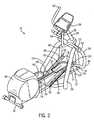
- FIG. 1illustrates an elevated front perspective view of an exercise device in accordance with the principles of the present invention.
- FIG. 2illustrates an elevated rear perspective view of the exercise device of FIG. 1 .
- FIG. 3illustrates a side view of the exercise device of FIG. 1 .
- FIG. 4illustrates a close-up perspective view of a portion of the exercise device of FIG. 1 that includes the abutment arm and curved attachment link of the engagement assembly.
- FIG. 5illustrates a close-up side view of the exercise device of FIG. 1 that includes the abutment arm and curved attachment link of the engagement assembly.
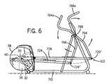
- FIG. 6illustrates an elevated side view of an alternative exercise device in accordance with the principles of the present invention.
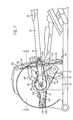
- FIG. 7is an adjustable stride elliptical mechanism in accordance with the principles of the present invention.
- FIG. 8shows a top view of the adjustable stride elliptical mechanism of FIG. 7 .
- FIG. 9is a schematic depicting one paths of the adjustable stride elliptical mechanism of FIG. 7 .
- FIG. 10is a schematic depicting another paths of the adjustable stride elliptical mechanism of FIG. 7 .
- FIGS. 1-3illustrate an embodiment of an exercise device 10 constructed in accordance with the principles of the present invention that exercises both the upper and lower body in associated motion.
- the exerciser 10includes a frame 12 that has a forward upright member 20 .
- the forward upright member 20extends upwardly and curves slightly rearward from a substantially horizontal, longitudinal central member 14 of the frame 12 .
- a center housing 38is provided near the rear region of the frame 12 . Center housing 38 is described in detail below with respect to FIGS. 7-11 .
- Left and right foot links 60 , 70each include a forward portion 62 , 72 , a rearward portion 64 , 74 , and a foot support portion 66 , 76 there between.
- the rearward portions 64 , 74 of the foot links 60 , 70extend into the center housing 38 as described in detail below such that the foot support portion 66 , 76 of the foot links travel in an elliptical path.
- the forward portions 62 , 72 of the foot links 60 , 70preferably are supported by rollers 68 , 78 , which engage guide tracks 42 , 52 that are mounted to the frame 12 .
- the guide trackscan be statically mounted to the frame 12 .
- the guide trackscan incorporate a mechanism such as a motor (not shown) and a lead screw (not shown) for selectively adjusting the inclination of the guide tracks.
- the forward portions 62 , 72 of the foot links 60 , 70are operatively connected to engagement assemblies 100 , 110 , which in turn are operatively connected to the coupling regions 86 , 96 of left and right swing arm mechanisms 80 , 90 , respectively.
- the swing arm mechanisms 80 , 90are rotatably connected to the forward upright member 20 of the frame 12 at their respective pivot points 84 , 94 .
- the swing arm mechanisms 80 , 90further contain left and right hand-gripping portions 82 , 92 .
- Each engagement assembly 100 , 110includes an abutment arm 106 , 116 , and a curved attachment link 104 , 114 , which together prevent the derailment of the foot link rollers 68 , 78 from the guide tracks 42 , 52 .
- the frame 12includes the longitudinal central member 14 that terminates at forward and rearward portions 16 , 18 .
- the forward portion 16 of the frame 12simply terminates at the end of the longitudinal central member 14
- the rearward portion 18terminates as a relatively shorter transverse member.
- other frame configurationscan be employed including, for example, a shorter transverse member being positioned at forward portion of the frame as well.
- the frame 12is composed of tubular members that are relatively light in weight but that provide substantial strength and rigidity.
- the frame 12may also be composed of solid members that provide the requisite strength and rigidity while maintaining a relatively lightweight.
- the forward upright member 20extends upwardly and slightly rearward from the forward portion 16 of the floor-engaging frame 12 .
- the upright member 20is slightly rearward curved; however, the forward member 20 may be configured at other upward angles without departing from the scope of the present invention.
- a relatively short, transversely oriented crossbar member 22is connected to the forward upright member 20 .
- Left and right balance arms 24 , 26can depend downwardly from each end of the crossbar member 22 to engage the floor on each side of the longitudinal central member 14 near the forward portion of the exercise device 10 , thereby increasing stability.
- these membersare composed of a material similar to that described above, and are formed in quasi-circular tubular configurations.
- a view screen 28is securely connected to the upper portion of the forward upright member 20 , at an orientation that is easily viewable to a user of the device 10 .
- Instructions for operating the device as well as courses being traveledmay be located on the view screen 24 in an exemplary embodiment.
- electronic devicesmay be incorporated into the exerciser device 10 such as timers, odometers, speedometers, heart rate indicators, energy expenditure recorders, controllers, etc. This information may be routed to the view screen 28 for ease of viewing for a user of the device 10 .
- the elliptical motion exerciser 10further contains longitudinally extending left and right foot links 60 , 70 .
- the foot links 60 , 70are illustrated in the shape of elongated, relatively thin beams.
- the foot links 60 , 70are aligned in approximately parallel relationship with the longitudinal central member 14 of the frame 12 .
- the foot support portions 66 , 76are positioned near the forward portions of the foot links 60 , 70 , and provide stable foot placement locations for the user of the device. Alternatively, the foot support portions can be positioned at any location between the front and rear ends of the foot link.
- the foot support portions 66 , 76are configured to form toe straps and/or toe and heel cups (not shown) which aid in forward motion recovery at the end of a rearward or forward striding motion of a user's foot.
- the exerciser device 10further contains left and right guide tracks 42 , 52 .
- the guide tracks 42 , 52can be completely separate members, or can be part of one single connected unit (as shown in FIGS. 4 and 5 ).
- the guide tracks 42 , 52attach to the longitudinal central member 14 of the frame 12 at an angled inclination. In one embodiment, the angle of inclination is approximately 30 degrees.
- the guide tracks 42 , 52can be connected to a height adjustment mechanism that can raise and lower the guide tracks 42 , 52 thereby adjusting the angle of inclination
- the upper surface of the guide tracks 42 , 52is shaped to contain two longitudinally extending, adjacent engagement grooves 44 , 54 .
- These engagement grooves 44 , 54give the upper surface of the guide tracks 42 , 52 a generally “W-shaped” cross-sectional configuration.
- the engagement grooves 44 , 54are specifically sized and shaped to correspondingly mate with the rollers 68 , 78 of the foot links 60 , 70 in order to assist in the lateral containment of the rollers 68 , 78 on the guide tracks.
- the lower surface of the guide tracks 42 , 52preferably contain longitudinally extending stabilizing troughs 56 (see FIG. 4 ).
- the left and right forward portions 62 , 72 of the foot links 60 , 70terminate in left and right engagement rollers 68 , 78 .
- the left and right engagement rollers 68 , 78ride along the above-described grooves 44 , 54 of the guide tracks 42 , 52 .
- the engagement rollers 68 , 78are actually pairs of rollers.
- the engagement rollers 68 , 78rotate about axles that are affixed to the forward portions 62 , 72 of the foot links 60 , 70 .
- the engagement rollers 68 , 78 at the front of the foot links 60 , 70translate back and forth the length of the guide tracks 42 , 52 in rolling engagement within the grooves 44 , 54 , as the foot support portions 66 , 76 of the foot links 60 , 70 travel in an elliptical path of motion, and the rearward portions 64 , 74 of the foot links 60 , 70 rotate about a transverse axle 34 .
- the engagement rollers 68 , 78could be replaced with sliding engagement mechanisms without departing from the scope of the present invention.
- each of the engagement assemblies 100 , 110operatively connect the forward portions 62 , 72 of the foot links 60 , 70 to the coupling regions 86 , 96 of swing arm mechanisms 80 , 90 .
- each of the engagement assemblies 100 , 110includes a curved attachment link 104 , 114 , and an abutment arm 106 , 116 .
- the abutment arms 106 , 116each have an abutment knob 118 .
- the abutment knobs 108 , 118are designed to withstand intermittent contact with the stabilizing troughs 56 on the lower surface of the guide tracks 42 , 52 during use of the exercise device 10 .
- the engagement assemblies 100 , 110could be configured such that the abutment knobs 118 were located on the curved attachment links 104 , 114 (or the abutment knobs could be deleted altogether), without departing from the scope of the present invention.
- the curved attachment links 104 , 114may not even be curved, but rather may be linear attachment links.
- Each curved attachment link 104 , 114is rotatably coupled to an abutment arm 106 , 116 .
- Each curved attachment link 104 , 114is fixedly secured to the forward portion 62 , 72 of a foot link 60 , 70 , and each abutment arm 106 , 116 is rotatably coupled to the coupling region 86 , 96 of a swing arm mechanism 80 , 90 .
- the exerciser device 10contains left and right swing arm mechanisms 80 , 90 .
- each swing arm mechanism 80 , 90contains a hand-gripping portion 82 , 92 , a pivot point 84 , 94 , and a coupling region 86 , 96 .
- the coupling regions 86 , 96 of the swing arm mechanisms 80 , 90rotatably connect to the engagement assemblies 100 , 110 , and turn to the foot support portions 66 , 76 of the foot links 60 , 70 .
- the pivot points 84 , 94rotatably secure the swing arm mechanisms 80 , 90 to each end of the crossbar member 22 of the frame 12 .
- the hand-gripping portions 82 , 92 of the swing arm mechanisms 80 , 90are grasped by the hands of the individual user, and allow upper body arm and shoulder exercising motions to be incorporated in conjunction with the reciprocal, elliptical exercising motion traced out by the feet of the user. As can be more readily understood with reference to FIGS.
- the linking of the swing arm mechanisms 80 , 90 to the foot links 60 , 70 , via the engagement assemblies 100 , 110 , and the rotational securement of the swing arm mechanisms 80 , 90 to the forward upright member 20 of the frame 12 at the pivot points 84 , 94results in generally rearward, elliptical motion of a hand-gripping portion being correspondingly linked to a generally forward, elliptical motion of a respective foot support portion, and vice versa.
- the exercise deviceincludes a frame 712 with a center housing 38 provided near the rear region of the frame 712 .
- First and second foot links, 724 , 726are provided.
- the foot links 724 , 726are generally elongated members having a first portion pivotally connected within center housing 38 in such a manner so as to permit travel of the first ends of the foot links 724 and 726 in an elliptical path of travel.
- a pair of arm links 764 and 766are provided. Each arm link 764 , 766 is pivotally supported by the frame 712 at support point 768 .
- the arm links 764 , 766are also pivotally coupled to the ends 724 ′′, 726 ′′ of the foot links 724 , 726 . Pivoting of the arm links 764 , 766 about the support point 768 causes the second ends 724 ′′, 726 ′′ of the foot links 724 , 726 to reciprocate along a curved path.
- the arm links 764 , 766also include handle portions 764 a , 766 a associated therewith. These handle portions may be configured to be gripped by a user and, during the operation of the device they also reciprocate, thereby providing upper body exercise.
- an axle mount 30is located toward the rearward portion 18 of the frame 12 .
- the axle mount 30is attached to the frame 12 and extends approximately upward from the substantially horizontal, longitudinal central member 14 .
- the transverse axle 34is rotatably housed in the upper region of the axle mount 30 .
- the regions of the axle mount 30 which house the ends of the transverse axle 34contain low friction engaging systems (not shown), such as bearing systems, to allow the transverse axle 34 to rotate with little resistance within the housing in the axle mount 30 .
- the transverse axle 34can be operatively coupled to a flywheel 40 contained within the center housing 38 .
- the present inventionfurther can include a brake system 32 , such as for example an eddy current brake assembly.
- the brake system 32can selectively apply a braking or retarding force on the rotation of the flywheel 40 via a drive belt 33 ( FIG. 7 ).
- a primary gear 121 and a secondary gear 123are provided.
- the primary gear 121is eke sized larger relative to the secondary gear 123 .
- the secondary gear 123is connected to the outboard end of crank 122 and is free to rotate as defined by the timing belt and primary gear 121 .
- a primary crank 122connects the axis of the primary gear 121 and the secondary gear 123 .
- a timing belt 125is provided connecting primary gear 121 to secondary gear 123 .
- the primary crank 122 and the timing belt 125allow the secondary gear 123 to rotate around primary gear 121 in a circular path created by the primary crank 122 , about the central axis of the primary gear 121 .
- alternative mechanismscan be substituted for the mechanisms of the preferred embodiment including but not limited to a cam mechanisms, alternative belt and gear mechanisms, chain mechanisms, etc.
- the size ratio between the primary gear 121 and secondary gear 123is such that the secondary gear 123 rotates about its own axis twice per one revolution around primary gear 121 .
- a secondary crank 124is pivotally attached to the secondary gear 123 .
- the secondary crank 124is pivotally attached to the rearward end 74 of the foot link 70 and thus controls the movement of the foot link. As the secondary gear 123 rotates around the primary gear 121 the secondary crank 124 rotates around the secondary gear 124 .
- the primary gear 121is secured on a support bracket 120 .
- the support bracket 120is best seen in FIG. 8 , which shows a top view of the adjustable stride elliptical mechanism of FIG. 7 .
- the support bracket 120is secured at the end opposite the primary gear 121 to an adjusting mechanism 129 ( FIG. 7 ).
- the adjusting mechanism 129can include a rotatable threaded member 131 operatively connected to an electronic motor 133 to impart rotation thereon.
- a threaded bolt follower 135Secured to the support bracket 120 at a hinged connection is a threaded bolt follower 135 .
- the threaded bolt follower 135is cooperatively engaged to the rotatable threaded member 131 .
- the rotatable threaded member 131includes an upper stop 135 and a lower stop 137 .
- the threaded bolt follower 135rises or falls on the rotatable threaded member 131 .
- the support bracket 120is pivoted upwardly or downwardly.
- the primary gear 121is rotated relative to the secondary gear 123 , thereby adjusting the clocking or the angular orientation of the crank 124 relative to the crank arm 122 .
- the adjusting mechanismcan be automatically adjusted by the user.
- electronicsconnect the electronic motor 133 to the view screen 28 such that the user can control the adjusting mechanism via the view screen.
- the adjusting mechanismcan incorporate a sensing system to sense the extension and retraction of the adjusting mechanism, and thus, the angle of inclination of the adjusting mechanism with respect to the frame or the ground. The angle of inclination of the adjusting mechanism can be transmitted to a CPU through an analog to digital interface and controller.
- FIGS. 9 and 10schematics depicting different paths of the adjustable stride elliptical mechanism are seen.
- a first orientation seen in FIG. 9the orientation of the primary gear 121 and the secondary gear 123 have been adjusted such that the secondary crank 124 extends outwardly relative to the primary crank 122 at the horizontal apex and inwardly at the vertical apex of the path.
- the useris presented with a relatively more horizontally skewed elliptical path.
- the userstands on the foot support portions 66 , 76 and grasps the hand-gripping portions 82 , 92 .
- the userimparts a rearward stepping motion on one of the foot support portions and a forward stepping motion on the other foot support portion, thereby causing the transverse axle 34 to rotate in a clockwise direction (when viewed from the right side as shown in FIG. 1 ), due to the crank arm assemblies 122 , 124 coupling the motion of the foot links 60 , 70 to the rotation of the transverse axle 34 .
- the userIn conjunction with the lower body action, the user also imparts a substantially forward pushing motion on one of the hand-gripping portions 82 , 92 and a substantially rearward pulling motion on the other hand-gripping portion 82 , 92 . Due to the rotatable connection of the coupling regions 86 , 96 of the swing arm mechanisms 80 , 90 to the forward ends 62 , 72 of the foot links 60 , 70 (via the engagement assemblies), and the rotational securement of the swing arm mechanisms 80 , 90 to the forward upright member 20 of the frame 12 at their pivot points 84 , 94 , each hand-gripping portion 82 , 92 moves forward as its respective foot support portion moves rearward, and vice versa.
- One of the advantages of the present inventionis that, to adjust the elliptical path in accordance with the invention, the user need not step off the exercise device or indeed, even stop or disrupt the exercise routine. Thus, the user can simply activate the automatic adjusting mechanism from the view screen during an exercise routine.
- the foot links 60 , 70are attached to the transverse axle 34 by the crank arm assemblies 122 , 124 such that one foot support portion moves substantially forward as the other foot support portion moves substantially rearward.
- one hand-gripping portionmoves forward as the other hand-gripping portion moves rearward (e.g., when the left hand-gripping portion 82 moves forward, the left foot support portion 66 moves rearward, while the right foot support portion 76 moves forward and the right hand-gripping portion 92 moves rearward). Therefore, the user can begin movement of the entire foot link and swing arm mechanism linkage by moving any foot support portion or hand-gripping portion, or preferably by moving all of them together.
Landscapes
- Health & Medical Sciences (AREA)
- Cardiology (AREA)
- Vascular Medicine (AREA)
- General Health & Medical Sciences (AREA)
- Physical Education & Sports Medicine (AREA)
- Rehabilitation Tools (AREA)
Abstract
Description
Claims (40)
Priority Applications (1)
| Application Number | Priority Date | Filing Date | Title |
|---|---|---|---|
| US11/060,123US7704192B2 (en) | 2005-02-17 | 2005-02-17 | Elliptical exercise equipment with adjustable stride |
Applications Claiming Priority (1)
| Application Number | Priority Date | Filing Date | Title |
|---|---|---|---|
| US11/060,123US7704192B2 (en) | 2005-02-17 | 2005-02-17 | Elliptical exercise equipment with adjustable stride |
Publications (2)
| Publication Number | Publication Date |
|---|---|
| US20060183605A1 US20060183605A1 (en) | 2006-08-17 |
| US7704192B2true US7704192B2 (en) | 2010-04-27 |
Family
ID=36816358
Family Applications (1)
| Application Number | Title | Priority Date | Filing Date |
|---|---|---|---|
| US11/060,123Expired - Fee RelatedUS7704192B2 (en) | 2005-02-17 | 2005-02-17 | Elliptical exercise equipment with adjustable stride |
Country Status (1)
| Country | Link |
|---|---|
| US (1) | US7704192B2 (en) |
Cited By (50)
| Publication number | Priority date | Publication date | Assignee | Title |
|---|---|---|---|---|
| US20110275485A1 (en)* | 2010-05-05 | 2011-11-10 | Paul William Eschenbach | Free track elliptical exercise apparatus |
| WO2011143439A1 (en) | 2010-05-13 | 2011-11-17 | Marko Vujicic | Exercise cycle with planetary gear system and rolling recoiled lateral motion system |
| US20120035023A1 (en)* | 2010-05-05 | 2012-02-09 | Paul William Eschenbach | Free terrain elliptical exercise apparatus |
| US20160001122A1 (en)* | 2014-07-02 | 2016-01-07 | Icon Health & Fitness, Inc. | Elliptical Exercise Machine with an Adjustable Connection |
| US9272181B2 (en)* | 2014-04-25 | 2016-03-01 | Precor Incorporated | Selectable stride elliptical |
| US9302148B1 (en)* | 2010-05-13 | 2016-04-05 | Shinn Fu Corporation | Epicyclic gear system for use in exercise equipment |
| US9468795B2 (en)* | 2014-04-25 | 2016-10-18 | Precor Incorporated | Selectable stride elliptical |
| US9586085B2 (en) | 2014-06-04 | 2017-03-07 | Precor Incorporated | Exercise apparatus with non-uniform foot pad transverse spacing |
| US9597540B2 (en) | 2012-02-14 | 2017-03-21 | Precor Incorporated | Adaptive motion exercise device |
| US9649529B1 (en)* | 2015-11-23 | 2017-05-16 | Larry D. Miller Trust | Elliptical exercise device with moving control tracks |
| USD797219S1 (en) | 2016-10-24 | 2017-09-12 | Precor Incorporated | Foot pad of an exercise device |
| USD797870S1 (en) | 2016-10-24 | 2017-09-19 | Precor Incorporated | Foot pad of an exercise device |
| USD798398S1 (en) | 2016-10-24 | 2017-09-26 | Precor Incorporated | Handle bar of an exercise device |
| USD798399S1 (en) | 2016-10-24 | 2017-09-26 | Precor Incorporated | Housing of an exercise device |
| WO2017184100A1 (en) | 2016-10-10 | 2017-10-26 | Solodovnik Sergii Anatoliyovych | Elliptical exercise device for simultaneous training of shoulder girdle, pelvic girdle and trunk muscles in a human |
| USD801451S1 (en) | 2016-10-24 | 2017-10-31 | Precor Incorporated | Exercise device |
| USD801454S1 (en) | 2016-10-24 | 2017-10-31 | Precor Incorporated | Rear housing of an exercise device |
| USD802062S1 (en) | 2016-10-24 | 2017-11-07 | Precor Incorporated | Shroud of an exercise device |
| US10065062B2 (en) | 2015-10-12 | 2018-09-04 | Precor Incorporated | Exercise apparatus with eddy current rail |
| US10080919B1 (en) | 2010-05-13 | 2018-09-25 | Shinn Fu Corporation | Epicyclic gear system for use in exercise equipment |
| US20180290014A1 (en)* | 2017-04-10 | 2018-10-11 | Oma Metal Industrial Co., Ltd. | Elliptical trainer |
| US10188890B2 (en) | 2013-12-26 | 2019-01-29 | Icon Health & Fitness, Inc. | Magnetic resistance mechanism in a cable machine |
| US10220259B2 (en) | 2012-01-05 | 2019-03-05 | Icon Health & Fitness, Inc. | System and method for controlling an exercise device |
| US10226396B2 (en) | 2014-06-20 | 2019-03-12 | Icon Health & Fitness, Inc. | Post workout massage device |
| US10252109B2 (en) | 2016-05-13 | 2019-04-09 | Icon Health & Fitness, Inc. | Weight platform treadmill |
| US10258828B2 (en) | 2015-01-16 | 2019-04-16 | Icon Health & Fitness, Inc. | Controls for an exercise device |
| US10272317B2 (en) | 2016-03-18 | 2019-04-30 | Icon Health & Fitness, Inc. | Lighted pace feature in a treadmill |
| US10279212B2 (en) | 2013-03-14 | 2019-05-07 | Icon Health & Fitness, Inc. | Strength training apparatus with flywheel and related methods |
| US10293211B2 (en) | 2016-03-18 | 2019-05-21 | Icon Health & Fitness, Inc. | Coordinated weight selection |
| US10343017B2 (en) | 2016-11-01 | 2019-07-09 | Icon Health & Fitness, Inc. | Distance sensor for console positioning |
| US10376736B2 (en) | 2016-10-12 | 2019-08-13 | Icon Health & Fitness, Inc. | Cooling an exercise device during a dive motor runway condition |
| US10391361B2 (en) | 2015-02-27 | 2019-08-27 | Icon Health & Fitness, Inc. | Simulating real-world terrain on an exercise device |
| US10426989B2 (en) | 2014-06-09 | 2019-10-01 | Icon Health & Fitness, Inc. | Cable system incorporated into a treadmill |
| US10433612B2 (en) | 2014-03-10 | 2019-10-08 | Icon Health & Fitness, Inc. | Pressure sensor to quantify work |
| US10441844B2 (en) | 2016-07-01 | 2019-10-15 | Icon Health & Fitness, Inc. | Cooling systems and methods for exercise equipment |
| US10471299B2 (en) | 2016-07-01 | 2019-11-12 | Icon Health & Fitness, Inc. | Systems and methods for cooling internal exercise equipment components |
| US10500473B2 (en) | 2016-10-10 | 2019-12-10 | Icon Health & Fitness, Inc. | Console positioning |
| US10537764B2 (en) | 2015-08-07 | 2020-01-21 | Icon Health & Fitness, Inc. | Emergency stop with magnetic brake for an exercise device |
| US10543395B2 (en) | 2016-12-05 | 2020-01-28 | Icon Health & Fitness, Inc. | Offsetting treadmill deck weight during operation |
| US10561894B2 (en) | 2016-03-18 | 2020-02-18 | Icon Health & Fitness, Inc. | Treadmill with removable supports |
| US10561877B2 (en) | 2016-11-01 | 2020-02-18 | Icon Health & Fitness, Inc. | Drop-in pivot configuration for stationary bike |
| US10625137B2 (en) | 2016-03-18 | 2020-04-21 | Icon Health & Fitness, Inc. | Coordinated displays in an exercise device |
| US10625114B2 (en) | 2016-11-01 | 2020-04-21 | Icon Health & Fitness, Inc. | Elliptical and stationary bicycle apparatus including row functionality |
| US10661114B2 (en) | 2016-11-01 | 2020-05-26 | Icon Health & Fitness, Inc. | Body weight lift mechanism on treadmill |
| US10668314B2 (en) | 2015-10-16 | 2020-06-02 | Precor Incorporated | Variable distance eddy current braking system |
| US10671705B2 (en) | 2016-09-28 | 2020-06-02 | Icon Health & Fitness, Inc. | Customizing recipe recommendations |
| US10702736B2 (en) | 2017-01-14 | 2020-07-07 | Icon Health & Fitness, Inc. | Exercise cycle |
| US10729965B2 (en) | 2017-12-22 | 2020-08-04 | Icon Health & Fitness, Inc. | Audible belt guide in a treadmill |
| US10953305B2 (en) | 2015-08-26 | 2021-03-23 | Icon Health & Fitness, Inc. | Strength exercise mechanisms |
| US11451108B2 (en) | 2017-08-16 | 2022-09-20 | Ifit Inc. | Systems and methods for axial impact resistance in electric motors |
Families Citing this family (5)
| Publication number | Priority date | Publication date | Assignee | Title |
|---|---|---|---|---|
| US7731634B2 (en)* | 2005-02-09 | 2010-06-08 | Precor Incorporated | Elliptical exercise equipment with stowable arms |
| US20070219065A1 (en)* | 2006-03-13 | 2007-09-20 | Anderson Timothy T | Climber apparatus |
| US7695408B2 (en)* | 2006-08-22 | 2010-04-13 | SJS Holdings, LLC | Elliptical exercise device and methods of use |
| JP7205026B2 (en)* | 2016-11-21 | 2023-01-17 | ヨハネス ヴァン ストラーテン ウィレム | training machine |
| CN106823272A (en)* | 2017-04-10 | 2017-06-13 | 广东奥玛健身器材有限公司 | A kind of elliptical machine |
Citations (35)
| Publication number | Priority date | Publication date | Assignee | Title |
|---|---|---|---|---|
| US5743834A (en) | 1995-01-25 | 1998-04-28 | Rodgers, Jr.; Robert E. | Stationary exercise apparatus with adjustable crank |
| US5919118A (en)* | 1997-12-16 | 1999-07-06 | Stearns; Kenneth W. | Elliptical exercise methods and apparatus |
| US5921894A (en) | 1997-10-21 | 1999-07-13 | Eschenbach; Paul William | Compact elliptical exercise apparatus |
| US5993359A (en) | 1997-10-21 | 1999-11-30 | Eschenbach; Paul William | Variable stroke elliptical exercise apparatus |
| US6024676A (en) | 1997-06-09 | 2000-02-15 | Eschenbach; Paul William | Compact cross trainer exercise apparatus |
| US6027430A (en) | 1997-03-31 | 2000-02-22 | Stearns; Kenneth W. | Exercise methods and apparatus |
| US6027431A (en) | 1997-04-26 | 2000-02-22 | Stearns; Kenneth W. | Exercise methods and apparatus with an adjustable crank |
| US6042512A (en) | 1999-07-27 | 2000-03-28 | Eschenbach; Paul William | Variable lift cross trainer exercise apparatus |
| DE19842490A1 (en) | 1998-09-16 | 2000-03-30 | Jin Chen Chuang | Exercise machine as home trainer has foundation base with axle and two foot rests movable radially relative to plates rotatable on axle and with pedals on foot rests moving on elliptical path when plates are turned |
| US6045488A (en) | 1999-08-11 | 2000-04-04 | Eschenbach; Paul William | Lift variable cross trainer exercise apparatus |
| US6077198A (en) | 1999-08-30 | 2000-06-20 | Eschenbach; Paul William | Selective lift cross trainer exercise apparatus |
| US6077196A (en) | 1999-10-01 | 2000-06-20 | Eschenbach; Paul William | Adjustable elliptical exercise apparatus |
| US6090013A (en) | 1998-12-07 | 2000-07-18 | Eschenbach; Paul William | Cross trainer exercise apparatus |
| US6090014A (en) | 1999-08-09 | 2000-07-18 | Eschenbach; Paul William | Adjustable cross trainer exercise apparatus |
| US6168552B1 (en) | 1992-11-04 | 2001-01-02 | Paul William Eschenbach | Selective lift elliptical exercise apparatus |
| US6183398B1 (en) | 1998-07-23 | 2001-02-06 | Unisen, Inc. | Exercise trainer with a stride multiplier |
| US6196948B1 (en) | 1998-05-05 | 2001-03-06 | Kenneth W. Stearns | Elliptical exercise methods and apparatus |
| US6206804B1 (en) | 1995-07-19 | 2001-03-27 | Joseph D. Maresh | Exercise methods and apparatus |
| US6210305B1 (en) | 1999-07-27 | 2001-04-03 | Paul William Eschenbach | Variable lift exercise apparatus with curved guide |
| US6217485B1 (en) | 1995-06-30 | 2001-04-17 | Joseph D. Maresh | Elliptical exercise methods and apparatus |
| US20010036886A1 (en) | 1997-06-09 | 2001-11-01 | Eschenbach Paul William | Variable stride elliptical exercise apparatus |
| US6334836B1 (en)* | 1997-07-14 | 2002-01-01 | Technogym S.R.L. | Motion producing mechanism and fitness machine incorporating same |
| US20020019298A1 (en) | 1997-06-09 | 2002-02-14 | Eschenbach Paul William | Pathfinder elliptical exercise machine |
| US6361476B1 (en)* | 1999-07-27 | 2002-03-26 | Paul William Eschenbach | Variable stride elliptical exercise apparatus |
| US20020055420A1 (en) | 1999-11-05 | 2002-05-09 | Stearns Kenneth W. | Exercise apparatus with elliptical foot motion |
| US6409632B1 (en) | 1996-09-09 | 2002-06-25 | Paul William Eschenbach | Compact elliptical exercise machine |
| US6422977B1 (en) | 1997-06-09 | 2002-07-23 | Paul William Eschenbach | Compact elliptical exercise machine with adjustment |
| US6436007B1 (en) | 1996-09-09 | 2002-08-20 | Paul William Eschenbach | Elliptical exercise machine with adjustment |
| US20020142890A1 (en) | 2001-03-30 | 2002-10-03 | Ohrt John Arthur | Exercise machine |
| US20020151411A1 (en) | 2001-04-16 | 2002-10-17 | Stearns Kenneth W. | Exercise apparatus with elliptical foot motion |
| US6482132B2 (en) | 1996-09-09 | 2002-11-19 | Paul William Eschenbach | Compact elliptical exercise apparatus |
| US20020198083A1 (en) | 1999-04-26 | 2002-12-26 | Yong-Ming Goh | Deep stride exercise machine |
| US20030092532A1 (en) | 2001-11-13 | 2003-05-15 | Cybex International, Inc. | Exercise device for cross training |
| US7270626B2 (en)* | 2004-01-23 | 2007-09-18 | Octane Fitness, Llc | Exercise equipment with automatic adjustment of stride length and/or stride height based upon direction of foot support rotation |
| US7361122B2 (en)* | 2004-02-18 | 2008-04-22 | Octane Fitness, Llc | Exercise equipment with automatic adjustment of stride length and/or stride height based upon speed of foot support |
- 2005
- 2005-02-17USUS11/060,123patent/US7704192B2/ennot_activeExpired - Fee Related
Patent Citations (40)
| Publication number | Priority date | Publication date | Assignee | Title |
|---|---|---|---|---|
| US6168552B1 (en) | 1992-11-04 | 2001-01-02 | Paul William Eschenbach | Selective lift elliptical exercise apparatus |
| US5743834A (en) | 1995-01-25 | 1998-04-28 | Rodgers, Jr.; Robert E. | Stationary exercise apparatus with adjustable crank |
| US20010056010A1 (en) | 1995-06-30 | 2001-12-27 | Stearns Kenneth W. | Elliptical exercise methods and apparatus |
| US6217485B1 (en) | 1995-06-30 | 2001-04-17 | Joseph D. Maresh | Elliptical exercise methods and apparatus |
| US6206804B1 (en) | 1995-07-19 | 2001-03-27 | Joseph D. Maresh | Exercise methods and apparatus |
| US6482132B2 (en) | 1996-09-09 | 2002-11-19 | Paul William Eschenbach | Compact elliptical exercise apparatus |
| US6436007B1 (en) | 1996-09-09 | 2002-08-20 | Paul William Eschenbach | Elliptical exercise machine with adjustment |
| US6409632B1 (en) | 1996-09-09 | 2002-06-25 | Paul William Eschenbach | Compact elliptical exercise machine |
| US6248045B1 (en) | 1997-03-31 | 2001-06-19 | Kenneth W. Stearns | Exercise method and apparatus |
| US6027430A (en) | 1997-03-31 | 2000-02-22 | Stearns; Kenneth W. | Exercise methods and apparatus |
| US6027431A (en) | 1997-04-26 | 2000-02-22 | Stearns; Kenneth W. | Exercise methods and apparatus with an adjustable crank |
| US6338698B1 (en) | 1997-04-26 | 2002-01-15 | Kenneth W. Stearns | Exercise method and apparatus with an adjustable crank |
| US6440042B2 (en) | 1997-06-09 | 2002-08-27 | Paul William Eschenbach | Pathfinder elliptical exercise machine |
| US6422977B1 (en) | 1997-06-09 | 2002-07-23 | Paul William Eschenbach | Compact elliptical exercise machine with adjustment |
| US20020019298A1 (en) | 1997-06-09 | 2002-02-14 | Eschenbach Paul William | Pathfinder elliptical exercise machine |
| US6024676A (en) | 1997-06-09 | 2000-02-15 | Eschenbach; Paul William | Compact cross trainer exercise apparatus |
| US20010036886A1 (en) | 1997-06-09 | 2001-11-01 | Eschenbach Paul William | Variable stride elliptical exercise apparatus |
| US6334836B1 (en)* | 1997-07-14 | 2002-01-01 | Technogym S.R.L. | Motion producing mechanism and fitness machine incorporating same |
| US5921894A (en) | 1997-10-21 | 1999-07-13 | Eschenbach; Paul William | Compact elliptical exercise apparatus |
| US5993359A (en) | 1997-10-21 | 1999-11-30 | Eschenbach; Paul William | Variable stroke elliptical exercise apparatus |
| US5919118A (en)* | 1997-12-16 | 1999-07-06 | Stearns; Kenneth W. | Elliptical exercise methods and apparatus |
| US6196948B1 (en) | 1998-05-05 | 2001-03-06 | Kenneth W. Stearns | Elliptical exercise methods and apparatus |
| US6183398B1 (en) | 1998-07-23 | 2001-02-06 | Unisen, Inc. | Exercise trainer with a stride multiplier |
| DE19842490A1 (en) | 1998-09-16 | 2000-03-30 | Jin Chen Chuang | Exercise machine as home trainer has foundation base with axle and two foot rests movable radially relative to plates rotatable on axle and with pedals on foot rests moving on elliptical path when plates are turned |
| US6090013A (en) | 1998-12-07 | 2000-07-18 | Eschenbach; Paul William | Cross trainer exercise apparatus |
| US6551218B2 (en) | 1999-04-26 | 2003-04-22 | Unisen, Inc. | Deep stride exercise machine |
| US20020198083A1 (en) | 1999-04-26 | 2002-12-26 | Yong-Ming Goh | Deep stride exercise machine |
| US6042512A (en) | 1999-07-27 | 2000-03-28 | Eschenbach; Paul William | Variable lift cross trainer exercise apparatus |
| US6210305B1 (en) | 1999-07-27 | 2001-04-03 | Paul William Eschenbach | Variable lift exercise apparatus with curved guide |
| US6361476B1 (en)* | 1999-07-27 | 2002-03-26 | Paul William Eschenbach | Variable stride elliptical exercise apparatus |
| US6090014A (en) | 1999-08-09 | 2000-07-18 | Eschenbach; Paul William | Adjustable cross trainer exercise apparatus |
| US6045488A (en) | 1999-08-11 | 2000-04-04 | Eschenbach; Paul William | Lift variable cross trainer exercise apparatus |
| US6077198A (en) | 1999-08-30 | 2000-06-20 | Eschenbach; Paul William | Selective lift cross trainer exercise apparatus |
| US6077196A (en) | 1999-10-01 | 2000-06-20 | Eschenbach; Paul William | Adjustable elliptical exercise apparatus |
| US20020055420A1 (en) | 1999-11-05 | 2002-05-09 | Stearns Kenneth W. | Exercise apparatus with elliptical foot motion |
| US20020142890A1 (en) | 2001-03-30 | 2002-10-03 | Ohrt John Arthur | Exercise machine |
| US20020151411A1 (en) | 2001-04-16 | 2002-10-17 | Stearns Kenneth W. | Exercise apparatus with elliptical foot motion |
| US20030092532A1 (en) | 2001-11-13 | 2003-05-15 | Cybex International, Inc. | Exercise device for cross training |
| US7270626B2 (en)* | 2004-01-23 | 2007-09-18 | Octane Fitness, Llc | Exercise equipment with automatic adjustment of stride length and/or stride height based upon direction of foot support rotation |
| US7361122B2 (en)* | 2004-02-18 | 2008-04-22 | Octane Fitness, Llc | Exercise equipment with automatic adjustment of stride length and/or stride height based upon speed of foot support |
Cited By (60)
| Publication number | Priority date | Publication date | Assignee | Title |
|---|---|---|---|---|
| US8668627B2 (en)* | 2010-05-05 | 2014-03-11 | Paul William Eschenbach | Free terrain elliptical exercise apparatus |
| US20110275485A1 (en)* | 2010-05-05 | 2011-11-10 | Paul William Eschenbach | Free track elliptical exercise apparatus |
| US20120035023A1 (en)* | 2010-05-05 | 2012-02-09 | Paul William Eschenbach | Free terrain elliptical exercise apparatus |
| US8133159B2 (en)* | 2010-05-05 | 2012-03-13 | Paul William Eschenbach | Free track elliptical exercise apparatus |
| US8876669B2 (en) | 2010-05-13 | 2014-11-04 | Shinn Fu Corporation | Exercise cycle with planetary gear system and rolling recoiled lateral motion system |
| CN102893063A (en)* | 2010-05-13 | 2013-01-23 | 瑞莱健康集团 | Exercise cycle with planetary gear system and rolling recoiled lateral motion system |
| EP2569556A4 (en)* | 2010-05-13 | 2015-10-14 | Shinn Fu Corp | EXERCISE BIKE WITH PLANETARY GEAR SYSTEM AND LATERAL MOTION MOVEMENT SYSTEM WITH RELAXATION |
| US9302148B1 (en)* | 2010-05-13 | 2016-04-05 | Shinn Fu Corporation | Epicyclic gear system for use in exercise equipment |
| US10080919B1 (en) | 2010-05-13 | 2018-09-25 | Shinn Fu Corporation | Epicyclic gear system for use in exercise equipment |
| WO2011143439A1 (en) | 2010-05-13 | 2011-11-17 | Marko Vujicic | Exercise cycle with planetary gear system and rolling recoiled lateral motion system |
| US10220259B2 (en) | 2012-01-05 | 2019-03-05 | Icon Health & Fitness, Inc. | System and method for controlling an exercise device |
| US9597540B2 (en) | 2012-02-14 | 2017-03-21 | Precor Incorporated | Adaptive motion exercise device |
| US10279212B2 (en) | 2013-03-14 | 2019-05-07 | Icon Health & Fitness, Inc. | Strength training apparatus with flywheel and related methods |
| US10188890B2 (en) | 2013-12-26 | 2019-01-29 | Icon Health & Fitness, Inc. | Magnetic resistance mechanism in a cable machine |
| US10433612B2 (en) | 2014-03-10 | 2019-10-08 | Icon Health & Fitness, Inc. | Pressure sensor to quantify work |
| US9604096B2 (en)* | 2014-04-25 | 2017-03-28 | Precor Incorporated | Selectable stride elliptical |
| US9272181B2 (en)* | 2014-04-25 | 2016-03-01 | Precor Incorporated | Selectable stride elliptical |
| US9468795B2 (en)* | 2014-04-25 | 2016-10-18 | Precor Incorporated | Selectable stride elliptical |
| US9586085B2 (en) | 2014-06-04 | 2017-03-07 | Precor Incorporated | Exercise apparatus with non-uniform foot pad transverse spacing |
| US10426989B2 (en) | 2014-06-09 | 2019-10-01 | Icon Health & Fitness, Inc. | Cable system incorporated into a treadmill |
| US10226396B2 (en) | 2014-06-20 | 2019-03-12 | Icon Health & Fitness, Inc. | Post workout massage device |
| US9586086B2 (en)* | 2014-07-02 | 2017-03-07 | Icon Health & Fitness, Inc. | Elliptical exercise machine with an adjustable connection |
| US20160001122A1 (en)* | 2014-07-02 | 2016-01-07 | Icon Health & Fitness, Inc. | Elliptical Exercise Machine with an Adjustable Connection |
| WO2016004091A1 (en)* | 2014-07-02 | 2016-01-07 | Icon Health & Fitness, Inc. | Elliptical exercise machine with an adjustable connection |
| US10258828B2 (en) | 2015-01-16 | 2019-04-16 | Icon Health & Fitness, Inc. | Controls for an exercise device |
| US10391361B2 (en) | 2015-02-27 | 2019-08-27 | Icon Health & Fitness, Inc. | Simulating real-world terrain on an exercise device |
| US10537764B2 (en) | 2015-08-07 | 2020-01-21 | Icon Health & Fitness, Inc. | Emergency stop with magnetic brake for an exercise device |
| US10953305B2 (en) | 2015-08-26 | 2021-03-23 | Icon Health & Fitness, Inc. | Strength exercise mechanisms |
| US10065062B2 (en) | 2015-10-12 | 2018-09-04 | Precor Incorporated | Exercise apparatus with eddy current rail |
| US10668314B2 (en) | 2015-10-16 | 2020-06-02 | Precor Incorporated | Variable distance eddy current braking system |
| US9649529B1 (en)* | 2015-11-23 | 2017-05-16 | Larry D. Miller Trust | Elliptical exercise device with moving control tracks |
| US10561894B2 (en) | 2016-03-18 | 2020-02-18 | Icon Health & Fitness, Inc. | Treadmill with removable supports |
| US10272317B2 (en) | 2016-03-18 | 2019-04-30 | Icon Health & Fitness, Inc. | Lighted pace feature in a treadmill |
| US10293211B2 (en) | 2016-03-18 | 2019-05-21 | Icon Health & Fitness, Inc. | Coordinated weight selection |
| US10625137B2 (en) | 2016-03-18 | 2020-04-21 | Icon Health & Fitness, Inc. | Coordinated displays in an exercise device |
| US10252109B2 (en) | 2016-05-13 | 2019-04-09 | Icon Health & Fitness, Inc. | Weight platform treadmill |
| US10471299B2 (en) | 2016-07-01 | 2019-11-12 | Icon Health & Fitness, Inc. | Systems and methods for cooling internal exercise equipment components |
| US10441844B2 (en) | 2016-07-01 | 2019-10-15 | Icon Health & Fitness, Inc. | Cooling systems and methods for exercise equipment |
| US10671705B2 (en) | 2016-09-28 | 2020-06-02 | Icon Health & Fitness, Inc. | Customizing recipe recommendations |
| WO2017184100A1 (en) | 2016-10-10 | 2017-10-26 | Solodovnik Sergii Anatoliyovych | Elliptical exercise device for simultaneous training of shoulder girdle, pelvic girdle and trunk muscles in a human |
| US10500473B2 (en) | 2016-10-10 | 2019-12-10 | Icon Health & Fitness, Inc. | Console positioning |
| US10857419B2 (en) | 2016-10-10 | 2020-12-08 | Tigerstep Fitness Se | Elliptical exercise device for simultaneous training of shoulder girdle, pelvic girdle and trunk muscles in a human |
| US10376736B2 (en) | 2016-10-12 | 2019-08-13 | Icon Health & Fitness, Inc. | Cooling an exercise device during a dive motor runway condition |
| USD797219S1 (en) | 2016-10-24 | 2017-09-12 | Precor Incorporated | Foot pad of an exercise device |
| USD797870S1 (en) | 2016-10-24 | 2017-09-19 | Precor Incorporated | Foot pad of an exercise device |
| USD798398S1 (en) | 2016-10-24 | 2017-09-26 | Precor Incorporated | Handle bar of an exercise device |
| USD798399S1 (en) | 2016-10-24 | 2017-09-26 | Precor Incorporated | Housing of an exercise device |
| USD801451S1 (en) | 2016-10-24 | 2017-10-31 | Precor Incorporated | Exercise device |
| USD801454S1 (en) | 2016-10-24 | 2017-10-31 | Precor Incorporated | Rear housing of an exercise device |
| USD802062S1 (en) | 2016-10-24 | 2017-11-07 | Precor Incorporated | Shroud of an exercise device |
| US10343017B2 (en) | 2016-11-01 | 2019-07-09 | Icon Health & Fitness, Inc. | Distance sensor for console positioning |
| US10625114B2 (en) | 2016-11-01 | 2020-04-21 | Icon Health & Fitness, Inc. | Elliptical and stationary bicycle apparatus including row functionality |
| US10661114B2 (en) | 2016-11-01 | 2020-05-26 | Icon Health & Fitness, Inc. | Body weight lift mechanism on treadmill |
| US10561877B2 (en) | 2016-11-01 | 2020-02-18 | Icon Health & Fitness, Inc. | Drop-in pivot configuration for stationary bike |
| US10543395B2 (en) | 2016-12-05 | 2020-01-28 | Icon Health & Fitness, Inc. | Offsetting treadmill deck weight during operation |
| US10702736B2 (en) | 2017-01-14 | 2020-07-07 | Icon Health & Fitness, Inc. | Exercise cycle |
| US10213644B2 (en)* | 2017-04-10 | 2019-02-26 | Oma Metal Industrial Co., Ltd. | Elliptical trainer |
| US20180290014A1 (en)* | 2017-04-10 | 2018-10-11 | Oma Metal Industrial Co., Ltd. | Elliptical trainer |
| US11451108B2 (en) | 2017-08-16 | 2022-09-20 | Ifit Inc. | Systems and methods for axial impact resistance in electric motors |
| US10729965B2 (en) | 2017-12-22 | 2020-08-04 | Icon Health & Fitness, Inc. | Audible belt guide in a treadmill |
Also Published As
| Publication number | Publication date |
|---|---|
| US20060183605A1 (en) | 2006-08-17 |
Similar Documents
| Publication | Publication Date | Title |
|---|---|---|
| US7704192B2 (en) | Elliptical exercise equipment with adjustable stride | |
| US8419598B2 (en) | Adjustable total body cross-training exercise device | |
| US6752744B2 (en) | Exercise device | |
| CA2327403C (en) | Exercise device | |
| US6277055B1 (en) | Flexibly coordinated stationary exercise device | |
| US5577985A (en) | Stationary exercise device | |
| US6398695B2 (en) | Elliptical exercise device | |
| US6849032B2 (en) | Exercise apparatus simulating skating motions | |
| US6123650A (en) | Independent elliptical motion exerciser | |
| US7780577B2 (en) | Pendulous exercise device | |
| US6835166B1 (en) | Exercise apparatus with elliptical foot motion | |
| EP0820329B1 (en) | Improved stationary exercise device | |
| US7731635B2 (en) | Cross training exercise device | |
| US5788610A (en) | Elliptical exercise machine with arm exercise | |
| US8062185B2 (en) | Exercise device for cross training | |
| US7691034B2 (en) | Total body elliptical exercise device with independent upper and lower body motion | |
| US20060281604A1 (en) | Cross training exercise device | |
| JPH11503660A (en) | Compact body training device | |
| JPH07250918A (en) | Stride movement apparatus provided with orbit curved upward | |
| US9144706B1 (en) | Exercise apparatus | |
| EP1036577B1 (en) | Flexibly coordinated stationary exercise device | |
| EP1537897A1 (en) | Exercise apparatus simulating skating motions | |
| CN2327407Y (en) | New structure of fitness equipment |
Legal Events
| Date | Code | Title | Description |
|---|---|---|---|
| AS | Assignment | Owner name:PRECOR INCORPORATED, WASHINGTON Free format text:ASSIGNMENT OF ASSIGNORS INTEREST;ASSIGNORS:DYER, DAVID E.;MARTI, FRANKLIN C.;STEWART, JONATHAN M.;AND OTHERS;REEL/FRAME:016310/0459 Effective date:20050211 Owner name:PRECOR INCORPORATED,WASHINGTON Free format text:ASSIGNMENT OF ASSIGNORS INTEREST;ASSIGNORS:DYER, DAVID E.;MARTI, FRANKLIN C.;STEWART, JONATHAN M.;AND OTHERS;REEL/FRAME:016310/0459 Effective date:20050211 | |
| REMI | Maintenance fee reminder mailed | ||
| LAPS | Lapse for failure to pay maintenance fees | ||
| REIN | Reinstatement after maintenance fee payment confirmed | ||
| FP | Lapsed due to failure to pay maintenance fee | Effective date:20140427 | |
| FEPP | Fee payment procedure | Free format text:PETITION RELATED TO MAINTENANCE FEES FILED (ORIGINAL EVENT CODE: PMFP); ENTITY STATUS OF PATENT OWNER: LARGE ENTITY Free format text:PETITION RELATED TO MAINTENANCE FEES GRANTED (ORIGINAL EVENT CODE: PMFG); ENTITY STATUS OF PATENT OWNER: LARGE ENTITY | |
| PRDP | Patent reinstated due to the acceptance of a late maintenance fee | Effective date:20150512 | |
| FPAY | Fee payment | Year of fee payment:4 | |
| SULP | Surcharge for late payment | ||
| FEPP | Fee payment procedure | Free format text:MAINTENANCE FEE REMINDER MAILED (ORIGINAL EVENT CODE: REM.) | |
| LAPS | Lapse for failure to pay maintenance fees | Free format text:PATENT EXPIRED FOR FAILURE TO PAY MAINTENANCE FEES (ORIGINAL EVENT CODE: EXP.) | |
| STCH | Information on status: patent discontinuation | Free format text:PATENT EXPIRED DUE TO NONPAYMENT OF MAINTENANCE FEES UNDER 37 CFR 1.362 | |
| FP | Lapsed due to failure to pay maintenance fee | Effective date:20180427 |