US7704098B2 - Registered jack with enhanced EMI protection - Google Patents
Registered jack with enhanced EMI protectionDownload PDFInfo
- Publication number
- US7704098B2 US7704098B2US12/177,465US17746508AUS7704098B2US 7704098 B2US7704098 B2US 7704098B2US 17746508 AUS17746508 AUS 17746508AUS 7704098 B2US7704098 B2US 7704098B2
- Authority
- US
- United States
- Prior art keywords
- mounting panel
- shield
- connector
- tabs
- flaps
- Prior art date
- Legal status (The legal status is an assumption and is not a legal conclusion. Google has not performed a legal analysis and makes no representation as to the accuracy of the status listed.)
- Active
Links
- 239000004020conductorSubstances0.000claimsdescription5
- PXHVJJICTQNCMI-UHFFFAOYSA-NNickelChemical compound[Ni]PXHVJJICTQNCMI-UHFFFAOYSA-N0.000description2
- 238000003780insertionMethods0.000description2
- 230000037431insertionEffects0.000description2
- 239000000463materialSubstances0.000description2
- 239000002184metalSubstances0.000description2
- 229910052751metalInorganic materials0.000description2
- 229920003023plasticPolymers0.000description2
- 239000004033plasticSubstances0.000description2
- 239000007787solidSubstances0.000description2
- 229910000881Cu alloyInorganic materials0.000description1
- ATJFFYVFTNAWJD-UHFFFAOYSA-NTinChemical compound[Sn]ATJFFYVFTNAWJD-UHFFFAOYSA-N0.000description1
- 239000003989dielectric materialSubstances0.000description1
- 230000000694effectsEffects0.000description1
- 230000005670electromagnetic radiationEffects0.000description1
- 229920003247engineering thermoplasticPolymers0.000description1
- 230000006855networkingEffects0.000description1
- 229910052759nickelInorganic materials0.000description1
- 239000012811non-conductive materialSubstances0.000description1
- 238000003825pressingMethods0.000description1
Images


Classifications
- H—ELECTRICITY
- H01—ELECTRIC ELEMENTS
- H01R—ELECTRICALLY-CONDUCTIVE CONNECTIONS; STRUCTURAL ASSOCIATIONS OF A PLURALITY OF MUTUALLY-INSULATED ELECTRICAL CONNECTING ELEMENTS; COUPLING DEVICES; CURRENT COLLECTORS
- H01R13/00—Details of coupling devices of the kinds covered by groups H01R12/70 or H01R24/00 - H01R33/00
- H01R13/73—Means for mounting coupling parts to apparatus or structures, e.g. to a wall
- H01R13/74—Means for mounting coupling parts in openings of a panel
- H01R13/748—Means for mounting coupling parts in openings of a panel using one or more screws
- H—ELECTRICITY
- H01—ELECTRIC ELEMENTS
- H01R—ELECTRICALLY-CONDUCTIVE CONNECTIONS; STRUCTURAL ASSOCIATIONS OF A PLURALITY OF MUTUALLY-INSULATED ELECTRICAL CONNECTING ELEMENTS; COUPLING DEVICES; CURRENT COLLECTORS
- H01R13/00—Details of coupling devices of the kinds covered by groups H01R12/70 or H01R24/00 - H01R33/00
- H01R13/648—Protective earth or shield arrangements on coupling devices, e.g. anti-static shielding
- H01R13/658—High frequency shielding arrangements, e.g. against EMI [Electro-Magnetic Interference] or EMP [Electro-Magnetic Pulse]
- H01R13/6581—Shield structure
- H01R13/6582—Shield structure with resilient means for engaging mating connector
- Y—GENERAL TAGGING OF NEW TECHNOLOGICAL DEVELOPMENTS; GENERAL TAGGING OF CROSS-SECTIONAL TECHNOLOGIES SPANNING OVER SEVERAL SECTIONS OF THE IPC; TECHNICAL SUBJECTS COVERED BY FORMER USPC CROSS-REFERENCE ART COLLECTIONS [XRACs] AND DIGESTS
- Y10—TECHNICAL SUBJECTS COVERED BY FORMER USPC
- Y10S—TECHNICAL SUBJECTS COVERED BY FORMER USPC CROSS-REFERENCE ART COLLECTIONS [XRACs] AND DIGESTS
- Y10S439/00—Electrical connectors
- Y10S439/939—Electrical connectors with grounding to metal mounting panel
Definitions
- the present inventionis directed to a registered jack (RJ) electrical connector and more specifically to an RJ connector having contacts to provide an electrical connection to a mounting frame to provide improved EMI protection.
- RJregistered jack
- a registered jackis a standardized physical interface for connecting telecommunications equipment (commonly, a telephone jack) or computer networking equipment.
- the standard designs for these connectors and their wiringare named RJ11, RJ14, RJ45, etc. These interface standards are most commonly used in North America, though some interfaces are used world-wide.
- An RJ connectoris typically configured to receive a plug that is formed generally as a rectangular solid, with contacts on one side and a latch on the opposite side, the latch being formed integrally with the rectangular solid out of a deformable plastic.
- the jackhas contacts to connect with those in the plug and a slot adapted to engage the latch. A user can insert or remove the plug by applying pressure on the latch to deform it and remove it from the slot.
- EMIelectromagnetic interference
- electromagnetic shieldingsuch as an enclosure formed of a conductive material.
- a high speed, low impedance shielded connectorhas a shield formed of sheet material and including multiple integral shield-to-plug contacts in a limited longitudinal space. Such contacts are forwardly facing, to reduce ground path lengths or are arranged substantially parallel to a plug insertion axis, to avoid development of high normal forces. Shielding of an array of contacts is enhanced by the use of transverse flanges having interfitting sections that provide effective shielding and allow close spacing or adjacent contacts in the array.
- the present inventionis directed to an electrical connector having a shield.
- the top of the shieldhas two rows of tabs; two flaps, one on either side of the shield; and a tab on the bottom.
- the flapshave mounting holes.
- the bottom tab and the two rows of top tabselectrically connect the shield to the mounting panel to provide extra EMI protection to the connector.
- the flapsprovide yet another connection to provide EMI protection.
- the two rows of tabscan be positioned and sized such that the rear row of tabs engages with a flange in the rear of the top of the mounting panel.
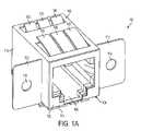
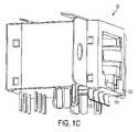
- FIGS. 1A-1Care views of a connector according to the preferred embodiment
- FIG. 2shows a mounting panel for use with the connector of FIGS. 1A-1C ;
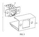
- FIG. 3shows the connector of FIGS. 1A-1C and mounting panel of FIG. 2 prior to insertion of the connector into the panel;
- FIGS. 4A-4Care views of the connector and the mounting panel as finally assembled with the connector inserted into the panel.
- FIGS. 1A-1Cshow three perspective views of electrical connector 100 according to the preferred embodiment.
- the connectorhas a connector body 102 made of plastic or another dielectric material enclosed in a conductive shield 104 , preferably formed of metal.
- Two rows of tabs 106 , 108are formed from the top 110 of the shield 104 .
- the shield 104has two flaps 112 , each with a hole 114 to be used as explained below, extending from the sides 116 of the shield 104 .
- the lower edge 118 of the front 120 of the shield 104has tabs 122 extending down therefrom.
- the connector body 102is formed of an engineering thermoplastic.
- the shield 104is preferably formed of a copper alloy plated with nickel, with the tabs 122 dipped in pure tin.
- other non-conductive materialscan be used to form connector body 102 and other conductive materials can be used to form the shield 104 .
- the connector 100can include any suitable electrical contacts, which are well known in the art and will therefore not be disclosed in detail here.
- FIG. 2shows a perspective view of a mounting panel 200 for use with the connector 100 .
- the mounting panel 200is formed of metal or other conducting material and has an upright portion 202 having formed therein a socket hole 204 for receiving a plug and additional holes 206 on either side of the socket hole 204 for receiving a screw, rivet, or other fastening means.
- a top portion 208 of the mounting panel 200has a flange 210 formed by folding back a rear edge 212 thereof.
- a bottom portion 214is also provided.
- a printed circuit board 216is contained within the mounting panel.
- FIGS. 3 and 4 A- 4 CThe manner in which the connector 100 and the mounting panel 200 are joined together will be explained with reference to FIGS. 3 and 4 A- 4 C.
- the connector 100is inserted into the mounting frame 200 from behind.
- screws, bolts rivets or other fastening means 402are used to secure the flaps 112 of the connector 100 to the upright portion 202 of the mounting panel 200 through holes 114 , 206 .
- the shield 104is in electrical contact with the mounting frame 200 in the following ways to provide EMI shielding.
- the tabs 122 and the flaps 112contact the upright portion 202
- the tabs 106 , 108contact the top portion.
- the rear tabs 106engage with the flange 210 .
Landscapes
- Details Of Connecting Devices For Male And Female Coupling (AREA)
Abstract
Description
The present invention is directed to a registered jack (RJ) electrical connector and more specifically to an RJ connector having contacts to provide an electrical connection to a mounting frame to provide improved EMI protection.
A registered jack (RJ) is a standardized physical interface for connecting telecommunications equipment (commonly, a telephone jack) or computer networking equipment. The standard designs for these connectors and their wiring are named RJ11, RJ14, RJ45, etc. These interface standards are most commonly used in North America, though some interfaces are used world-wide.
An RJ connector is typically configured to receive a plug that is formed generally as a rectangular solid, with contacts on one side and a latch on the opposite side, the latch being formed integrally with the rectangular solid out of a deformable plastic. The jack has contacts to connect with those in the plug and a slot adapted to engage the latch. A user can insert or remove the plug by applying pressure on the latch to deform it and remove it from the slot.
Registered jacks, like electrical and electronic equipment in general, are susceptible to electromagnetic interference (EMI), which is a (usually undesirable) disturbance that affects an electrical circuit due to electromagnetic radiation emitted from an external source. The disturbance may interrupt, obstruct, or otherwise degrade or limit the effective performance of the circuit. To mitigate the effects of EMI, it is common to use electromagnetic shielding, such as an enclosure formed of a conductive material.
An example of a connector with electromagnetic shielding is shown in U.S. Pat. No. 5,865,646 to Ortega et al. A high speed, low impedance shielded connector has a shield formed of sheet material and including multiple integral shield-to-plug contacts in a limited longitudinal space. Such contacts are forwardly facing, to reduce ground path lengths or are arranged substantially parallel to a plug insertion axis, to avoid development of high normal forces. Shielding of an array of contacts is enhanced by the use of transverse flanges having interfitting sections that provide effective shielding and allow close spacing or adjacent contacts in the array.
However, it would be desirable to increase the electromagnetic shielding still further.
It is therefore an object of the invention to provide improved EMI shielding for an RJ connector or the like.
To achieve the above and other objects, the present invention is directed to an electrical connector having a shield. The top of the shield has two rows of tabs; two flaps, one on either side of the shield; and a tab on the bottom. The flaps have mounting holes. When the connector is attached to a mounting panel, screws are driven through the holes in the flaps and corresponding holes in the mounting panel to secure the connector. The bottom tab and the two rows of top tabs electrically connect the shield to the mounting panel to provide extra EMI protection to the connector. The flaps provide yet another connection to provide EMI protection. The two rows of tabs can be positioned and sized such that the rear row of tabs engages with a flange in the rear of the top of the mounting panel.
A preferred embodiment of the present invention will be set forth in detail with reference to the drawings, in which:
A preferred embodiment of the present invention will be set forth in detail with reference to the drawings, in which like reference numerals refer to like elements or steps throughout.
Preferably, theconnector body 102 is formed of an engineering thermoplastic. Theshield 104 is preferably formed of a copper alloy plated with nickel, with thetabs 122 dipped in pure tin. However, other non-conductive materials can be used to formconnector body 102 and other conductive materials can be used to form theshield 104.
Theconnector 100 can include any suitable electrical contacts, which are well known in the art and will therefore not be disclosed in detail here.
The manner in which theconnector 100 and themounting panel 200 are joined together will be explained with reference to FIGS.3 and4A-4C. As shown inFIG. 3 , theconnector 100 is inserted into themounting frame 200 from behind. Once that is done, as shown inFIGS. 4A-4C , screws, bolts rivets or other fastening means402 are used to secure theflaps 112 of theconnector 100 to theupright portion 202 of themounting panel 200 throughholes shield 104 is in electrical contact with themounting frame 200 in the following ways to provide EMI shielding. Thetabs 122 and theflaps 112 contact theupright portion 202, and thetabs rear tabs 106 engage with theflange 210.
While a preferred embodiment of the present invention has been set forth above, those skilled in the art who have reviewed the present disclosure will readily appreciate that other embodiments are possible within the scope of the invention. For example, whenever a row of three tabs is shown, more or fewer tabs can be used instead. Also, recitations of materials are illustrative rather than limiting. Therefore, the present invention should be construed as limited only by the appended claims.
Claims (6)
1. An electrical connector that is shielded against electromagnetic interference when attached to a mounting panel, the connector comprising:
a connector body; and
a shield surrounding the connector body, the shield being formed of an electrically conductive material and comprising:
a plurality of rows of tabs extending upwardly from an upper surface of the shield for making electrical contact with an upper portion of the mounting panel;
a plurality of flaps extending from a front surface of the shield for securing the shield to the mounting panel and also for making electrical contact with the mounting panel; and
at least one tab extending downwardly from the shield for making electrical contact with the mounting panel.
2. The electrical connector ofclaim 1 , wherein each of the flaps has a mounting hole formed therein.
3. The electrical connector ofclaim 1 , wherein, in the plurality of rows of tabs, one of the rows of tabs is configured to engage with a flange formed in the mounting panel.
4. An assembly comprising:
a mounting panel comprising an upper portion; and
an electrical connector attached to the mounting panel, the electrical connector being shielded against electromagnetic interference when attached to the mounting panel, the connector comprising:
a connector body; and
a shield surrounding the connector body, the shield being formed of an electrically conductive material and comprising:
a plurality of rows of tabs extending upwardly from an upper surface of the shield for making electrical contact with the upper portion of the mounting panel;
a plurality of flaps extending from a front surface of the shield for securing the shield to the mounting panel and also for making electrical contact with the mounting panel; and
at least one tab extending downwardly from the shield for making electrical contact with the mounting panel.
5. The assembly ofclaim 4 , wherein each of the flaps has a mounting hole formed therein, and wherein the mounting panel has mounting holes formed therein corresponding to the mounting holes in the flaps.
6. The assembly ofclaim 4 , wherein the upper portion of the mounting panel has a flanged formed therein, and wherein, in the plurality of rows of tabs, one of the rows of tabs is configured to engage with the flange.
Priority Applications (1)
| Application Number | Priority Date | Filing Date | Title |
|---|---|---|---|
| US12/177,465US7704098B2 (en) | 2008-07-22 | 2008-07-22 | Registered jack with enhanced EMI protection |
Applications Claiming Priority (1)
| Application Number | Priority Date | Filing Date | Title |
|---|---|---|---|
| US12/177,465US7704098B2 (en) | 2008-07-22 | 2008-07-22 | Registered jack with enhanced EMI protection |
Publications (2)
| Publication Number | Publication Date |
|---|---|
| US20100022131A1 US20100022131A1 (en) | 2010-01-28 |
| US7704098B2true US7704098B2 (en) | 2010-04-27 |
Family
ID=41569046
Family Applications (1)
| Application Number | Title | Priority Date | Filing Date |
|---|---|---|---|
| US12/177,465ActiveUS7704098B2 (en) | 2008-07-22 | 2008-07-22 | Registered jack with enhanced EMI protection |
Country Status (1)
| Country | Link |
|---|---|
| US (1) | US7704098B2 (en) |
Cited By (10)
| Publication number | Priority date | Publication date | Assignee | Title |
|---|---|---|---|---|
| US20110002079A1 (en)* | 2008-03-20 | 2011-01-06 | Celem Passive Components Ltd. | Sideways conduction cooled high-power capacitor |
| US8011958B1 (en)* | 2010-05-19 | 2011-09-06 | Amphenol East Asia Electronic Technology (Shenzhen) Ltd. | E-easy series connector assembly with shielding function |
| US20120064776A1 (en)* | 2010-09-14 | 2012-03-15 | Hon Hai Precision Industry Co., Ltd. | Receptacle connector having a stabilizing outer shell |
| US8157593B1 (en) | 2010-12-16 | 2012-04-17 | Hewlett-Packard Development Company, L.P. | Method of shielding a connector module from electromagnetic interference with elongate members of conductive material and related apparatus |
| US20130078850A1 (en)* | 2011-09-26 | 2013-03-28 | Inventec Corporation | Panel module and power input connector fixing structure thereof |
| US20140080363A1 (en)* | 2012-09-14 | 2014-03-20 | Japan Aviation Electronics Industry, Limited | Connector |
| US20140308849A1 (en)* | 2013-04-15 | 2014-10-16 | Hon Hai Precision Industry Co., Ltd. | Electrical connector having a structure for avoiding high voltage conduction |
| US9178308B1 (en)* | 2014-05-26 | 2015-11-03 | Hyundai Motor Company | Shield connector for vehicle |
| US9847607B2 (en) | 2014-04-23 | 2017-12-19 | Commscope Technologies Llc | Electrical connector with shield cap and shielded terminals |
| CN112670771A (en)* | 2019-10-16 | 2021-04-16 | 广濑电机株式会社 | Connector with a locking member |
Families Citing this family (1)
| Publication number | Priority date | Publication date | Assignee | Title |
|---|---|---|---|---|
| KR20150052092A (en)* | 2012-08-30 | 2015-05-13 | 테이진 가부시키가이샤 | Microneedle array coated with drug composition |
Citations (31)
| Publication number | Priority date | Publication date | Assignee | Title |
|---|---|---|---|---|
| US5766041A (en) | 1996-05-31 | 1998-06-16 | The Whitaker Corporation | Shield member for panel mount connector |
| US5788538A (en)* | 1996-07-31 | 1998-08-04 | Berg Technology, Inc. | Shield for modular jack |
| US5989069A (en) | 1997-10-16 | 1999-11-23 | Speed Tech Corp. | Electric jack |
| US6257935B1 (en) | 2000-09-14 | 2001-07-10 | Hon Hai Precision Ind. Co., Ltd. | Receptacle connector having an anti-mismating mechanism |
| US6283796B1 (en) | 2000-03-23 | 2001-09-04 | Hon Hai Precision Ind. Co., Ltd. | RJ-receptacle connector with anti-incorrect-insertion device |
| US6319064B1 (en) | 1999-06-22 | 2001-11-20 | Fci Americas Technology, Inc. | Modular jack with filter insert and contact therefor |
| US6319070B1 (en) | 2000-08-08 | 2001-11-20 | Hon Hai Precision Ind. Co., Ltd. | RJ-receptacle connector with anti-mismating device |
| US20010046807A1 (en) | 1998-12-18 | 2001-11-29 | Marshall Robert E. | Electrical connector having mounting posts adapted to be received by a printed wiring board |
| US6328603B1 (en) | 2001-03-28 | 2001-12-11 | Speed Tech Corp. | Electric connector grounding structure |
| US6334787B1 (en) | 2001-04-27 | 2002-01-01 | Speed Tech Corp. | Electric connector with a space-saving LED lead-out wire and circuit board arrangement |
| US6431819B1 (en) | 1998-10-26 | 2002-08-13 | Rite-Hite Holding Corporation | Power-up vehicle restraint |
| US6450837B1 (en) | 2001-10-29 | 2002-09-17 | Hon Hai Precision Ind. Co., Ltd. | Electrical connector having surge suppressing device |
| US6478611B1 (en) | 2001-11-08 | 2002-11-12 | Hon Hai Precision Ind. Co., Ltd. | Electrical connector with visual indicator |
| US6544076B2 (en) | 2001-07-10 | 2003-04-08 | Alan L. Pocrass | Dual function RJ connector |
| US20030082954A1 (en) | 2001-11-01 | 2003-05-01 | Espenshade Leonard K. | Cross-talk reduced modular jack |
| US6558203B2 (en) | 2001-07-10 | 2003-05-06 | Alan L. Pocrass | Multi-function RJ-type modular connector |
| US6595805B2 (en) | 2001-07-10 | 2003-07-22 | Alan L. Pocrass | Dual function RJ connector |
| US6623306B2 (en) | 2001-12-26 | 2003-09-23 | Hon Hai Precision Ind. Co., Ltd. | Solder mask configuration for a printed circuit board of a modular jack |
| US6638112B1 (en) | 2002-10-24 | 2003-10-28 | Hon Hai Precision Ind. Co., Ltd. | Modular jack having subassembly of PCBs and magnetic box |
| US6702618B1 (en) | 2002-10-24 | 2004-03-09 | Hon Hai Precision Ind. Co., Ltd. | Modular jack having improved grounding plate |
| US6752664B2 (en) | 2002-10-24 | 2004-06-22 | Hon Hai Precision Ind. Co., Ltd. | Modular jack having magnetic module with support and alignment mechanism |
| US6881096B2 (en) | 2002-04-15 | 2005-04-19 | Lantronix, Inc. | Compact serial-to-ethernet conversion port |
| US6918791B2 (en) | 2003-11-11 | 2005-07-19 | Hon Hai Precision Ind. Co., Ltd. | Electrical connector having a reliable internal circuit board |
| US6918790B2 (en) | 2003-07-29 | 2005-07-19 | Hon Hai Precision Ind. Co., Ltd. | Electrical connector having printed circuit board mounted therein |
| US20050186853A1 (en) | 2004-02-24 | 2005-08-25 | Delta Electronics, Inc. | Connector |
| US7090535B2 (en) | 2003-11-21 | 2006-08-15 | Hon Hai Precision Ind. Co., Ltd. | Electrical connector capable of bearing high voltage |
| US20070049072A1 (en)* | 2005-08-25 | 2007-03-01 | Japan Aviation Electronics Industry, Limited | Board mount connector suitable for automatic mounting |
| US20070270044A1 (en) | 2006-05-17 | 2007-11-22 | Yakov Belopolsky | High Speed Modular Jack |
| US7309260B2 (en) | 2002-04-15 | 2007-12-18 | Lantronix, Inc. | Wireless communication module |
| US20080171468A1 (en)* | 2007-01-15 | 2008-07-17 | Tyco Electronics Corporation | Movable Connector Bracket For End Mounting Panel Members |
| US20080242127A1 (en)* | 2007-03-27 | 2008-10-02 | Tyco Electronics Corporation | Transceiver receptacle assembly |
- 2008
- 2008-07-22USUS12/177,465patent/US7704098B2/enactiveActive
Patent Citations (36)
| Publication number | Priority date | Publication date | Assignee | Title |
|---|---|---|---|---|
| US5766041A (en) | 1996-05-31 | 1998-06-16 | The Whitaker Corporation | Shield member for panel mount connector |
| US5788538A (en)* | 1996-07-31 | 1998-08-04 | Berg Technology, Inc. | Shield for modular jack |
| US5989069A (en) | 1997-10-16 | 1999-11-23 | Speed Tech Corp. | Electric jack |
| US6431819B1 (en) | 1998-10-26 | 2002-08-13 | Rite-Hite Holding Corporation | Power-up vehicle restraint |
| US20010046807A1 (en) | 1998-12-18 | 2001-11-29 | Marshall Robert E. | Electrical connector having mounting posts adapted to be received by a printed wiring board |
| US6328599B1 (en) | 1998-12-18 | 2001-12-11 | Fci Americas Technology, Inc. | Electrical connector having mounting posts adapted to be received by a printed wiring board |
| US6319064B1 (en) | 1999-06-22 | 2001-11-20 | Fci Americas Technology, Inc. | Modular jack with filter insert and contact therefor |
| US6283796B1 (en) | 2000-03-23 | 2001-09-04 | Hon Hai Precision Ind. Co., Ltd. | RJ-receptacle connector with anti-incorrect-insertion device |
| US6319070B1 (en) | 2000-08-08 | 2001-11-20 | Hon Hai Precision Ind. Co., Ltd. | RJ-receptacle connector with anti-mismating device |
| US6257935B1 (en) | 2000-09-14 | 2001-07-10 | Hon Hai Precision Ind. Co., Ltd. | Receptacle connector having an anti-mismating mechanism |
| US6328603B1 (en) | 2001-03-28 | 2001-12-11 | Speed Tech Corp. | Electric connector grounding structure |
| US6334787B1 (en) | 2001-04-27 | 2002-01-01 | Speed Tech Corp. | Electric connector with a space-saving LED lead-out wire and circuit board arrangement |
| US6592397B2 (en) | 2001-07-10 | 2003-07-15 | Alan L. Pocrass | Dual function RJ connector |
| US6544076B2 (en) | 2001-07-10 | 2003-04-08 | Alan L. Pocrass | Dual function RJ connector |
| US6558203B2 (en) | 2001-07-10 | 2003-05-06 | Alan L. Pocrass | Multi-function RJ-type modular connector |
| US6568965B2 (en) | 2001-07-10 | 2003-05-27 | Alan L. Pocrass | Multi-functional RJ type modulator connector for selectively receiving two RJ plugs of differing configurations |
| US6595805B2 (en) | 2001-07-10 | 2003-07-22 | Alan L. Pocrass | Dual function RJ connector |
| US6450837B1 (en) | 2001-10-29 | 2002-09-17 | Hon Hai Precision Ind. Co., Ltd. | Electrical connector having surge suppressing device |
| US20030082954A1 (en) | 2001-11-01 | 2003-05-01 | Espenshade Leonard K. | Cross-talk reduced modular jack |
| US6478611B1 (en) | 2001-11-08 | 2002-11-12 | Hon Hai Precision Ind. Co., Ltd. | Electrical connector with visual indicator |
| US6623306B2 (en) | 2001-12-26 | 2003-09-23 | Hon Hai Precision Ind. Co., Ltd. | Solder mask configuration for a printed circuit board of a modular jack |
| US7018242B2 (en) | 2002-04-15 | 2006-03-28 | Lantronix, Inc. | Serial-to-ethernet conversion port |
| US6881096B2 (en) | 2002-04-15 | 2005-04-19 | Lantronix, Inc. | Compact serial-to-ethernet conversion port |
| US7309260B2 (en) | 2002-04-15 | 2007-12-18 | Lantronix, Inc. | Wireless communication module |
| US6638112B1 (en) | 2002-10-24 | 2003-10-28 | Hon Hai Precision Ind. Co., Ltd. | Modular jack having subassembly of PCBs and magnetic box |
| US6752664B2 (en) | 2002-10-24 | 2004-06-22 | Hon Hai Precision Ind. Co., Ltd. | Modular jack having magnetic module with support and alignment mechanism |
| US6702618B1 (en) | 2002-10-24 | 2004-03-09 | Hon Hai Precision Ind. Co., Ltd. | Modular jack having improved grounding plate |
| US6918790B2 (en) | 2003-07-29 | 2005-07-19 | Hon Hai Precision Ind. Co., Ltd. | Electrical connector having printed circuit board mounted therein |
| US6918791B2 (en) | 2003-11-11 | 2005-07-19 | Hon Hai Precision Ind. Co., Ltd. | Electrical connector having a reliable internal circuit board |
| US7090535B2 (en) | 2003-11-21 | 2006-08-15 | Hon Hai Precision Ind. Co., Ltd. | Electrical connector capable of bearing high voltage |
| US20050186853A1 (en) | 2004-02-24 | 2005-08-25 | Delta Electronics, Inc. | Connector |
| US20070049072A1 (en)* | 2005-08-25 | 2007-03-01 | Japan Aviation Electronics Industry, Limited | Board mount connector suitable for automatic mounting |
| US20070270044A1 (en) | 2006-05-17 | 2007-11-22 | Yakov Belopolsky | High Speed Modular Jack |
| US20080171468A1 (en)* | 2007-01-15 | 2008-07-17 | Tyco Electronics Corporation | Movable Connector Bracket For End Mounting Panel Members |
| US20080242127A1 (en)* | 2007-03-27 | 2008-10-02 | Tyco Electronics Corporation | Transceiver receptacle assembly |
| US7452216B2 (en)* | 2007-03-27 | 2008-11-18 | Tyco Electronics Corporation | Transceiver receptacle assembly |
Cited By (14)
| Publication number | Priority date | Publication date | Assignee | Title |
|---|---|---|---|---|
| US20110002079A1 (en)* | 2008-03-20 | 2011-01-06 | Celem Passive Components Ltd. | Sideways conduction cooled high-power capacitor |
| US8373970B2 (en)* | 2008-03-20 | 2013-02-12 | Celem Passive Components Ltd. | Sideways conduction cooled high-power capacitor |
| US8011958B1 (en)* | 2010-05-19 | 2011-09-06 | Amphenol East Asia Electronic Technology (Shenzhen) Ltd. | E-easy series connector assembly with shielding function |
| US20120064776A1 (en)* | 2010-09-14 | 2012-03-15 | Hon Hai Precision Industry Co., Ltd. | Receptacle connector having a stabilizing outer shell |
| US8157593B1 (en) | 2010-12-16 | 2012-04-17 | Hewlett-Packard Development Company, L.P. | Method of shielding a connector module from electromagnetic interference with elongate members of conductive material and related apparatus |
| US8616916B2 (en)* | 2011-09-26 | 2013-12-31 | Inventec Corporation | Panel module and power input connector fixing structure thereof |
| US20130078850A1 (en)* | 2011-09-26 | 2013-03-28 | Inventec Corporation | Panel module and power input connector fixing structure thereof |
| US20140080363A1 (en)* | 2012-09-14 | 2014-03-20 | Japan Aviation Electronics Industry, Limited | Connector |
| US8979585B2 (en)* | 2012-09-14 | 2015-03-17 | Japan Aviation Electronics Industry, Limited | Connector |
| US20140308849A1 (en)* | 2013-04-15 | 2014-10-16 | Hon Hai Precision Industry Co., Ltd. | Electrical connector having a structure for avoiding high voltage conduction |
| US9847607B2 (en) | 2014-04-23 | 2017-12-19 | Commscope Technologies Llc | Electrical connector with shield cap and shielded terminals |
| US10476212B2 (en) | 2014-04-23 | 2019-11-12 | Commscope Technologies Llc | Electrical connector with shield cap and shielded terminals |
| US9178308B1 (en)* | 2014-05-26 | 2015-11-03 | Hyundai Motor Company | Shield connector for vehicle |
| CN112670771A (en)* | 2019-10-16 | 2021-04-16 | 广濑电机株式会社 | Connector with a locking member |
Also Published As
| Publication number | Publication date |
|---|---|
| US20100022131A1 (en) | 2010-01-28 |
Similar Documents
| Publication | Publication Date | Title |
|---|---|---|
| US7704098B2 (en) | Registered jack with enhanced EMI protection | |
| EP1356549B1 (en) | Connector interface and retention system for high-density connector | |
| US6595801B1 (en) | Electrical connector with electrically isolated ESD and EMI shields | |
| US6469905B1 (en) | Guide rail device for receiving a GBIC module | |
| CN101499575B (en) | Electrical connector | |
| US6220896B1 (en) | Shielded header | |
| US8007317B2 (en) | Cable connector assembly with an improved shell | |
| TWI758401B (en) | Electrical connector having a mating connector interface | |
| US8454382B2 (en) | Electrical connector having grounding shield | |
| US6206728B1 (en) | Shielded electrical connector system | |
| US8070517B2 (en) | Electrical connector having an improved spring member for abutting against a metal plate | |
| US20100068922A1 (en) | Cable connector assembly having improved grounding member | |
| CN102946029A (en) | Grounding structures for header and receptacle assemblies | |
| US8366456B2 (en) | Cable connector assembly with aligned cable arrangement | |
| US20100003852A1 (en) | Electrical connector with improved grounding | |
| US6948980B2 (en) | Shielded electrical connector | |
| US9136650B2 (en) | Electrical connector | |
| EP0604213B1 (en) | Edge connector shield | |
| TW201524039A (en) | Receptacle assembly having a plurality of termination points | |
| US6364708B1 (en) | Electrical connector with improved supporting devices | |
| US6699071B1 (en) | Electrical connector with retention mechanism of outer shell | |
| US20100112859A1 (en) | Shielded connector system | |
| US6210228B1 (en) | Shielded electrical connector | |
| US6619984B2 (en) | Electrical connector having improved shielding | |
| US6077119A (en) | Shielding device for a connector unit and the connector unit using the same |
Legal Events
| Date | Code | Title | Description |
|---|---|---|---|
| AS | Assignment | Owner name:AMPHENOL CORPORATION, CONNECTICUT Free format text:ASSIGNMENT OF ASSIGNORS INTEREST;ASSIGNORS:LAMBIE, KENT;OUYANG, JEFF;REEL/FRAME:021786/0551;SIGNING DATES FROM 20081001 TO 20081006 Owner name:AMPHENOL CORPORATION,CONNECTICUT Free format text:ASSIGNMENT OF ASSIGNORS INTEREST;ASSIGNORS:LAMBIE, KENT;OUYANG, JEFF;SIGNING DATES FROM 20081001 TO 20081006;REEL/FRAME:021786/0551 | |
| STCF | Information on status: patent grant | Free format text:PATENTED CASE | |
| FPAY | Fee payment | Year of fee payment:4 | |
| SULP | Surcharge for late payment | ||
| MAFP | Maintenance fee payment | Free format text:PAYMENT OF MAINTENANCE FEE, 8TH YEAR, LARGE ENTITY (ORIGINAL EVENT CODE: M1552) Year of fee payment:8 | |
| MAFP | Maintenance fee payment | Free format text:PAYMENT OF MAINTENANCE FEE, 12TH YEAR, LARGE ENTITY (ORIGINAL EVENT CODE: M1553); ENTITY STATUS OF PATENT OWNER: LARGE ENTITY Year of fee payment:12 |