US7703903B2 - Ink reservoir for inkjet printhead - Google Patents
Ink reservoir for inkjet printheadDownload PDFInfo
- Publication number
- US7703903B2 US7703903B2US11/482,978US48297806AUS7703903B2US 7703903 B2US7703903 B2US 7703903B2US 48297806 AUS48297806 AUS 48297806AUS 7703903 B2US7703903 B2US 7703903B2
- Authority
- US
- United States
- Prior art keywords
- ink
- membrane
- ink reservoir
- reservoir according
- pressure
- Prior art date
- Legal status (The legal status is an assumption and is not a legal conclusion. Google has not performed a legal analysis and makes no representation as to the accuracy of the status listed.)
- Expired - Fee Related, expires
Links
Images


Classifications
- B—PERFORMING OPERATIONS; TRANSPORTING
- B41—PRINTING; LINING MACHINES; TYPEWRITERS; STAMPS
- B41J—TYPEWRITERS; SELECTIVE PRINTING MECHANISMS, i.e. MECHANISMS PRINTING OTHERWISE THAN FROM A FORME; CORRECTION OF TYPOGRAPHICAL ERRORS
- B41J2/00—Typewriters or selective printing mechanisms characterised by the printing or marking process for which they are designed
- B41J2/005—Typewriters or selective printing mechanisms characterised by the printing or marking process for which they are designed characterised by bringing liquid or particles selectively into contact with a printing material
- B41J2/01—Ink jet
- B41J2/17—Ink jet characterised by ink handling
- B41J2/175—Ink supply systems ; Circuit parts therefor
- B41J2/17503—Ink cartridges
- B41J2/17556—Means for regulating the pressure in the cartridge
Definitions
- the present inventionrelates to inkjet printers.
- the inventionrelates to the supply of ink to inkjet printheads.
- the inkjet printheads in the above cross referenced documentshave an array of nozzles, each nozzle having an associated ink ejection actuator within a nozzle chamber. Ink from a cartridge or other reservoir is fed to the chambers where the ejection actuators force drops of ink through the nozzle for printing.
- the inventionwill be described with specific reference to ink cartridges. However, it will be appreciated that the invention equally applies to any fluid reservoir for supplying a printhead.
- the inkis retained in the chambers by the surface tension of the ink meniscus that forms across the nozzle. If the meniscus bulges outwardly, it can ‘pin’ itself to the nozzle rim to hold the ink in the chamber. However, if it contacts paper dust or other contaminants on the nozzle rim, the meniscus can be unpinned from the rim and ink will leak out of the printhead through the nozzle.
- ink cartridgesare designed so that the hydrostatic pressure of the ink at the nozzles is less than atmospheric pressure. This causes the meniscus across the nozzle openings to be concave or drawn inwards. Paper dust or other particulate contaminants are less likely to contact the meniscus when it is inverted into the nozzle. Furthermore, a positive pressure in the ink chamber helps to drive the flow of ink leaking from the chamber once the meniscus is compromised by paper dust.
- the negative pressure in the chambersis limited by two factors. It can not be strong enough to de-prime the chambers (i.e. suck the ink out of the chambers and back towards the cartridge) and it must be less than the ejection pressure generated by the ejection drop ejection actuators. However, if the negative pressure is too weak, the nozzles can leak ink if the printhead is jolted or shaken. While this can happen during use, it is more likely to occur during the shipping and handling of the primed printheads.
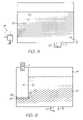
- FIG. 1Another way of generating a negative pressure in the ink chambers is shown in FIG. 1 .
- a piece of foam or porous material 2is placed in the cartridge 1 over the outlet 3 .
- the foam 2has a section that is saturated with ink 4 , and a section 5 that may be wet with ink, but not saturated.
- the top of the cartridge 1is vented to atmosphere through the air maze 7 .
- Capillary action(represented by arrow 6 ) draws the ink from the saturated section 4 into the unsaturated section 5 . This continues until it is balanced by the weight of the increased hydrostatic pressure, or ‘head’ of ink drawn upwards by the capillary action 6 .
- the hydrostatic pressure at the top of the saturated section 4is less than atmospheric because of capillary action into the unsaturated section 5 . From there, the hydrostatic pressure increases towards the outlet 3 , and if connected to the printhead (not shown), it continues to increase down to the nozzle openings (assuming they are the lowest points in the printhead).
- the proportion of saturated foam to unsaturated foamsuch that the hydrostatic pressure of the ink at the nozzle is less than atmospheric, the ink meniscus will form inwardly.
- the negative pressure at the nozzlewill increase as the ink level in the cartridge drops. As the negative pressure must be established at the nozzles when the cartridge is first installed, and the negative pressure increases as the ink in the cartridge is used, there are practical limits on the volume of ink that can be supplied by cartridges of this type. As previously discussed, the negative pressure at the nozzles can not be stronger than the ejection actuators or greater than the de-prime threshold.
- the cartridge 1essentially has two chambers 8 and 9 ; one holding the foam 2 and the other holding ink 10 only.
- the chambersare connected by a narrow passage 11 at the floor 12 of the cartridge.
- the hydrostatic ink pressure below the balance line 13is the same in each chamber for corresponding heights.
- the negative pressure at the nozzlesis provided by capillary action 6 to the unsaturated section of the foam 5 .
- the foam 2and therefore the printhead, is fed additional ink from the second chamber 9 .
- tiny bubbles of air 15form at the opening 11 and rise up to the head space 14 .
- This arrangementis more volumetrically efficient but still suffers from many of the problems associated with the design shown in FIG. 1 .
- a substantial amount of inkremains in the foam when the cartridge is discarded and the second chamber 9 introduces an extra degree of complexity for manufacturing and charging with ink.
- the present Applicanthas developed a range of pagewidth printheads for high speed, 1600 d.p.i. full color printing.
- High speed pagewidth printheadsintroduce additional problems for cartridges with foam inserts.
- the cartridgeis supplying a much greater number of nozzles than a scanning printhead.
- the nozzleshave a higher firing rate. Therefore the ink flow rate out of the cartridge is much greater than that of a scanning printhead.
- the fluidic drag caused by the foam insertcan starve the nozzles and retard the chamber refill rate. More porous foam will have less fluidic drag but also much less capillary force.
- pagewidth printheadshave a generally elongate structure. By definition they must extend (at least) the width of a page. If one end of the printhead is raised during installation or shipping, the head of ink above the lower-most nozzles can be much greater than when the printhead is horizontal. This increase can overcome the negative pressure at the lower nozzles and cause leakage.
- the present inventionaims to overcome or ameliorate at least one of these problems, or provide a useful alternative to the prior art.
- the present inventionprovides an ink reservoir for an inkjet printhead, the reservoir comprising:
- the pressure regulatoris a valve relief valve.
- the pressure regulatoris a porous member with a first surface for exposure to atmosphere and a second surface for contacting the ink in the container; wherein during use, air at the first surface moves to the second surface and forms bubbles.
- the present inventionuses the suction provided the printhead to drop the pressure in the cartridge to the desired negative pressure and then uses a pressure regulator at the air inlet to keep control the level of negative pressure.
- the regulatorcan be a valve member that allows air into cartridge at a specified pressure difference or it could also be porous material with a particular ‘bubble point’. The term ‘bubble point’ is explained below.
- valve membersuch as a simple pressure relief valve in the wall of the cartridge allows the negative pressure inside the cartridge to be closely controlled.
- the valveBy locating the valve so that it is slightly elevated relative to the ink outlet, the hydrostatic pressure of the ink at the outlet remains constant and so the pressure in the nozzles chambers is also constant (ignoring fluctuations from movement or jarring of the printhead).
- the pressure valvecan also provide a convenient point from which the initially charge the cartridge with ink.
- the nozzles of a pagewidth printheadgenerate relatively high suction on the cartridge so the threshold pressure difference can be relatively high.
- the pressure differenceshould at least be greater than 10 mm H 2 O, but a more practical level would be greater than 300 mm H 2 O.
- the negative pressureis strong enough to counter the higher hydrostatic pressures in the lowest nozzles if the printhead is ever angled or held vertically.
- the pressure relief valvecan be relatively simple and inexpensive, a porous member with a suitable bubble point is an even simpler and cheaper form of pressure regulation.
- the bubble point of porous materialis the air pressure applied to one side of the material in order form a bubble on another side that is immersed in ink.
- the porous materialcan be in the form of a membrane, mesh or open cell foam.
- foamit is important to note that its function is not to provide any capillary action for generating negative pressure and therefore it is much denser and smaller than the foam inserts used in the prior art cartridges.
- a foam member used in the present inventionabsorbs and retains very little ink compared to the foam inserts of the prior art.
- porous membrane, mesh or foam membercan be positioned toward the bottom of the cartridge to maintain a constant hydrostatic pressure at or near the ink outlet. Firing the nozzles will drop the pressure in the cartridge until the bubble point is reached. Continued firing of the nozzles does not further reduce the pressure as tiny air bubbles permeate through the membrane, mesh or dense foam member.
- the cartridgeshave an increasing head space of air as the ink is used. If the internal surface of the air permeable member is exposed to the air in the cartridge it can dry out and become much more permeable to air. If this happens the cartridge will effectively vent to atmosphere and the negative pressure is lost. To safeguard against this, the internal surface of the permeable member must be kept wet.
- the air inletalso has an air maze structure so in the event that ink permeates through the air permeable material, it does not leak to the exterior of the cartridge.
- the ink outletmay have a filter covering to stop air bubbles from getting to the nozzles.
- the filtershould not create a significant flow restriction for the ink.
- the outletis not obstructed by a foam insert as it is in the prior art cartridges, and therefore cartridges according to the present invention can supply ink at a high flow rate. As previously discussed, high speed pagewidth printheads require high ink flow rates.
- FIG. 1is a schematic section view of a prior art ink cartridge
- FIG. 2is a schematic section view of another prior art ink cartridge
- FIG. 3is a schematic section view of an ink cartridge according to the present invention.
- FIGS. 4 and 5are partial schematic section views of alternatives to the ink cartridge shown in FIG. 3 ;
- FIGS. 6 and 7are schematic section views of a double membrane cartridge in different orientations
- FIG. 8is a schematic section view of a cartridge with single membrane and hydrophilic internal wall
- FIG. 9is a partial schematic section view of an alternative to cartridge shown in FIG. 8 ;
- FIG. 10is a schematic sectioned perspective of a cartridge according to the invention showing the possible configuration of the tortuous air inlet flow path.
- FIG. 3is a simplified sketch of the invention to illustrate the basic operating principles. It uses a membrane 16 positioned near the floor 12 of the cartridge 1 to maintain a negative pressure at the control level 13 . Unlike the prior art cartridges of FIG. 1 and 2 , the hydrostatic pressure at the control level is set by the bubble point of the membrane. As previously discussed the bubble point of porous material is the gas pressure that needs to be applied to one side to force liquid from the largest wetted pore on the immersed side.
- the nozzlescan fire into a blotter or the like to lower the pressure in the cartridge.
- the pressure at the control level 13drops to the bubble point, small bubbles 15 will form on the internal surface of the membrane 16 and rise into the head space 14 . This slightly increases the pressure in the cartridge and the bubbles 15 stop forming on the membrane 16 .
- the hydrostatic pressure at control level 13is known.
- the control level 13keeps a constant hydrostatic pressure (equal to the regulator threshold pressure).
- FIG. 4uses a small block of dense open cell foam 17 instead of the membrane 16 of the previous embodiment.
- the bubble point of the foamsets the hydrostatic pressure at the control level 13 and the cartridge 1 operates in way as the membrane embodiment.
- the foamis denser than that used in the prior art cartridges so that the bubble point is high enough to generate the required negative pressure. However, it absorbs some ink and will stay wet (temporarily at least) if it is exposed to the air in the headspace. It will be appreciated that the foam can be easily exposed to the air in the cartridge when the printhead is moved or transported.
- the air inlet 7has an air maze structure. If ink happens to permeate through the porous material (membrane 16 in FIG. 3 and foam element 17 in FIG. 4 ), it does not leak to the exterior of the cartridge.
- the ink outlet 3may have a filter 23 covering to stop air bubbles from getting to the nozzles. However, the filter should not create a significant flow restriction for the ink.
- the outlet 3is not obstructed by a foam insert as it is in the prior art cartridges and so can supply ink at a high flow rate. As previously discussed, high speed pagewidth printheads require high ink flow rates.
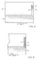
- FIG. 5is even simpler in the sense that it does not need an inlet air maze 7 or internal passage covered by a membrane, mesh or foam element. Instead, a pressure relief valve 18 in the wall of the cartridge opens at a threshold pressure which sets the hydrostatic pressure at the control level 13 . Furthermore, if the internal side of the valve is exposed to the air in the cartridge, it does not vent to atmosphere like a dry membrane or foam. It opens when the pressure difference reaches the specified threshold and so maintains a negative pressure in the cartridge even after the ink has dropped below the control level 13 (although the pressure at the outlet 3 will slightly decrease as the level drops below the valve 18 ).
- the pressure relief valve 18can be a simple ball-type check valve that is biased into its seat to keep the unit cost to a minimum. It is unlikely to be cheaper than a membrane or foam element however it does provide a convenient means for initially charging the cartridges with ink and allows the cartridge to be very compact.
- FIGS. 6 and 7show a solution to the problem of membrane drying discussed above.
- a pair of membranes 19 and 20is used.
- the membranesare closely spaced so that the ink between them does not drain out if the cartridge is positioned such that they are in the air of the headspace 14 (see FIG. 7 ). As long as the internal surface of the outer membrane 19 stays wet, the cartridge 1 will not vent to atmosphere.
- FIGS. 8 and 9show another version of the membrane embodiment that also avoids the membrane drying problem.
- the cartridge of FIG. 8has a membrane 16 in the wall of the cartridge 1 . Closely adjacent the internal surface of the membrane 16 is an internal wall 21 .
- the internal wall 21should be approximately 1 mm away from the membrane.
- the internal wall 21is made of a hydrophilic material so that ink is held between the wall and the membrane 16 by capillary action when the ink level drops below the membrane.
- the tiny air bubbles 15 permeating through the membrane 16rise up through the ink held the wall 21 and into the air space 14 .
- wicking material 22is placed between the wall 21 and the membrane 16 to enhance the capillary action.
- the wicking materialcan be fabric, mesh or particulate material.
- the wicking materialalso damps any jolts or impacts to the printhead that might otherwise dislodge the ink from between the membrane 16 and the wall 21 .
- Cartridges according to the inventionare particularly suited to use with the Applicant's range of pagewidth printheads. These printheads will typically generate 1200 mm.H 2 O of suction pressure per color which is much higher than that generated by a scanning type printhead.
- a strong suctionallows the threshold pressure of the valve of air permeable material to be relatively high, which in turn allows a stronger negative pressure in the cartridge.
- a stronger negative pressure in the cartridgemakes the nozzles less prone to leakage, particularly the lowest nozzles of a pagewidth printhead that is moved from it horizontal orientation.
- the unobstructed outletsallow a high ink flow rate to the nozzles.
- FIG. 10shows how the air inlet maze might work in practice.
- the container 8holds a quantity of ink 10 and encloses the inlet maze 26 , the air expansion chamber 27 , inlet membrane 16 and outlet filter 23 .
- Inlet opening 25is open to atmosphere and the outlet 3 forms a sealed fluid connection with the printhead when the cartridge is installed.
- the cartridgeis filled through a sealable fill hole 28 in the top wall.
- the entire container 8can be rigid or, parts of the container can be flexible material to lower materials costs.
- the large side walls 30 and 31can be air and ink impermeable film sealed to the periphery of a rigid wall middle section.
- the air inlet tube 26follows a tortuous path to the membrane 16 .
- the tortuous pathhas irregular changes in direction so that any ink seeping into the tube 26 is very unlikely to leak out of the inlet opening 25 even if the cartridge is rotated through different orientation during transport.
- the cartridgeneeds to go through a precise sequence of rotations in different directions. The risk of this happening by chance during transport and handling is negligible.
- the air inlet tube 26incorporates an air expansion chamber 27 .
- the cartridgeis expected to be exposed to a wide range of temperatures—approximately 35° C. Any ink trapped in the line 26 can be forced to the opening 25 by the increased air pressure.
- the air expansion chamber 27is relatively large compared to the tube 26 and so has more capacity to accommodate an expanding gas.
- the inlet membrane 16 and the associated-chamber 29is smaller than that of the ink outlet ( 23 and 24 respectively). This accounts for the high rate of ink supply required by the pagewidth inkjet printheads whilst also filtering the ink that leaves through the outlet 3 .
- the large diameter filter 23 and associated chamber 24means that the filter surface area is high so that the filter can keep a small pore size to remove all detrimental contaminants, without being an undue flow constriction in the ink supply.
- the tortuous air inlet path 26 and air expansion chamber 27effectively prevent ink leakage during transport and handling, with minimal added complexity and cost.
- the membraneis at the floor of the cartridge so that the negative ink pressure at the outlet 3 will be the bubble point of the membrane regardless of the amount if ink 10 that has been consumed. Furthermore, the vast majority of the ink will be consumed before the membrane is exposed and vents the interior to atmosphere. At this point the cartridge needs to be replaced however, only a small amount of ink will remain in the cartridge when it is discarded.
Landscapes
- Ink Jet (AREA)
Abstract
Description
| 7,637,588 | 11/482,970 | 11/482,968 | 7,607,755 | 11/482,971 |
| 11/482,969 | 7,530,663 | 7,467,846 | 11/482,962 | 11/482,963 |
| 11/482,956 | 11/482,954 | 11/482,974 | 11/482,974 | 11/482,987 |
| 11/482,959 | 11/482,960 | 11/482,961 | 11/482,964 | 11/482,965 |
| 7,510,261 | 11/482,973 | 11/482,982 | 7,637,602 | 11/482,984 |
| 7,530,446 | 11/482,990 | 11/482,986 | 11/482,985 | 11/482,967 |
| 11/482,966 | 11/482,988 | 11/482,989 | 11/482,980 | 7,571,906 |
| 11/482,953 | 11/482,977 | |||
| 09/517,539 | 6,566,858 | 6,331,946 | 6,246,970 | 6,442,525 | 09/517,384 | 09/505,951 |
| 6,374,354 | 09/517,608 | 6,816,968 | 6,757,832 | 6,334,190 | 6,745,331 | 09/517,541 |
| 10/203,559 | 10/203,560 | 10/203,564 | 10/636,263 | 10/636,283 | 10/866,608 | 10/902,889 |
| 10/902,833 | 10/940,653 | 10/942,858 | 10/727,181 | 10/727,162 | 10/727,163 | 10/727,245 |
| 10/727,204 | 10/727,233 | 10/727,280 | 10/727,157 | 10/727,178 | 10/727,210 | 10/727,257 |
| 10/727,238 | 10/727,251 | 10/727,159 | 10/727,180 | 10/727,179 | 10/727,192 | 10/727,274 |
| 10/727,164 | 10/727,161 | 10/727,198 | 10/727,158 | 10/754,536 | 10/754,938 | 10/727,227 |
| 10/727,160 | 10/934,720 | 11/212,702 | 11/272,491 | 10/296,522 | 6,795,215 | 10/296,535 |
| 09/575,109 | 6,805,419 | 6,859,289 | 6,977,751 | 6,398,332 | 6,394,573 | 6,622,923 |
| 6,747,760 | 6,921,144 | 10/884,881 | 10/943,941 | 10/949,294 | 11/039,866 | 11/123,011 |
| 6,986,560 | 7,008,033 | 11/148,237 | 11/248,435 | 11/248,426 | 10/922,846 | 10/922,845 |
| 10/854,521 | 10/854,522 | 10/854,488 | 10/854,487 | 10/854,503 | 10/854,504 | 10/854,509 |
| 10/854,510 | 10/854,496 | 10/854,497 | 10/854,495 | 10/854,498 | 10/854,511 | 10/854,512 |
| 10/854,525 | 10/854,526 | 10/854,516 | 10/854,508 | 10/854,507 | 10/854,515 | 10/854,506 |
| 10/854,505 | 10/854,493 | 10/854,494 | 10/854,489 | 10/854,490 | 10/854,492 | 10/854,491 |
| 10/854,528 | 10/854,523 | 10/854,527 | 10/854,524 | 10/854,520 | 10/854,514 | 10/854,519 |
| 10/854,513 | 10/854,499 | 10/854,501 | 10/854,500 | 10/854,502 | 10/854,518 | 10/854,517 |
| 10/934,628 | 11/212,823 | 10/728,804 | 10/728,952 | 10/728,806 | 6,991,322 | 10/728,790 |
| 10/728,884 | 10/728,970 | 10/728,784 | 10/728,783 | 10/728,925 | 6,962,402 | 10/728,803 |
| 10/728,780 | 10/728,779 | 10/773,189 | 10/773,204 | 10/773,198 | 10/773,199 | 6,830,318 |
| 10/773,201 | 10/773,191 | 10/773,183 | 10/773,195 | 10/773,196 | 10/773,186 | 10/773,200 |
| 10/773,185 | 10/773,192 | 10/773,197 | 10/773,203 | 10/773,187 | 10/773,202 | 10/773,188 |
| 10/773,194 | 10/773,193 | 10/773,184 | 11/008,118 | 11/060,751 | 11/060,805 | 11/188,017 |
| 11/298,773 | 11/298,774 | 11/329,157 | 6,623,101 | 6,406,129 | 6,505,916 | 6,457,809 |
| 6,550,895 | 6,457,812 | 10/296,434 | 6,428,133 | 6,746,105 | 10/407,212 | 10/407,207 |
| 10/683,064 | 10/683,041 | 6,750,901 | 6,476,863 | 6,788,336 | 11/097,308 | 11/097,309 |
| 11/097,335 | 11/097,299 | 11/097,310 | 11/097,213 | 11/210,687 | 11/097,212 | 11/212,637 |
| 11/246,687 | 11/246,718 | 11/246,685 | 11/246,686 | 11/246,703 | 11/246,691 | 11/246,711 |
| 11/246,690 | 11/246,712 | 11/246,717 | 11/246,709 | 11/246,700 | 11/246,701 | 11/246,702 |
| 11/246,668 | 11/246,697 | 11/246,698 | 11/246,699 | 11/246,675 | 11/246,674 | 11/246,667 |
| 11/246,684 | 11/246,672 | 11/246,673 | 11/246,683 | 11/246,682 | 10/760,272 | 10/760,273 |
| 10/760,187 | 10/760,182 | 10/760,188 | 10/760,218 | 10/760,217 | 10/760,216 | 10/760,233 |
| 10/760,246 | 10/760,212 | 10/760,243 | 10/760,201 | 10/760,185 | 10/760,253 | 10/760,255 |
| 10/760,209 | 10/760,208 | 10/760,194 | 10/760,238 | 10/760,234 | 10/760,235 | 10/760,183 |
| 10/760,189 | 10/760,262 | 10/760,232 | 10/760,231 | 10/760,200 | 10/760,190 | 10/760,191 |
| 10/760,227 | 10/760,207 | 10/760,181 | 10/815,625 | 10/815,624 | 10/815,628 | 10/913,375 |
| 10/913,373 | 10/913,374 | 10/913,372 | 10/913,377 | 10/913,378 | 10/913,380 | 10/913,379 |
| 10/913,376 | 10/913,381 | 10/986,402 | 11/172,816 | 11/172,815 | 11/172,814 | 11/003,786 |
| 11/003,616 | 11/003,418 | 11/003,334 | 11/003,600 | 11/003,404 | 11/003,419 | 11/003,700 |
| 11/003,601 | 11/003,618 | 11/003,615 | 11/003,337 | 11/003,698 | 11/003,420 | 6,984,017 |
| 11/003,699 | 11/071,473 | 11/003,463 | 11/003,701 | 11/003,683 | 11/003,614 | 11/003,702 |
| 11/003,684 | 11/003,619 | 11/003,617 | 11/293,800 | 11/293,802 | 11/293,801 | 11/293,808 |
| 11/293,809 | 11/246,676 | 11/246,677 | 11/246,678 | 11/246,679 | 11/246,680 | 11/246,681 |
| 11/246,714 | 11/246,713 | 11/246,689 | 11/246,671 | 11/246,670 | 11/246,669 | 11/246,704 |
| 11/246,710 | 11/246,688 | 11/246,716 | 11/246,715 | 11/246,707 | 11/246,706 | 11/246,705 |
| 11/246,708 | 11/246,693 | 11/246,692 | 11/246,696 | 11/246,695 | 11/246,694 | 11/293,832 |
| 11/293,838 | 11/293,825 | 11/293,841 | 11/293,799 | 11/293,796 | 11/293,797 | 11/293,798 |
| 10/760,254 | 10/760,210 | 10/760,202 | 10/760,197 | 10/760,198 | 10/760,249 | 10/760,263 |
| 10/760,196 | 10/760,247 | 10/760,223 | 10/760,264 | 10/760,244 | 10/760,245 | 10/760,222 |
| 10/760,248 | 10/760,236 | 10/760,192 | 10/760,203 | 10/760,204 | 10/760,205 | 10/760,206 |
| 10/760,267 | 10/760,270 | 10/760,259 | 10/760,271 | 10/760,275 | 10/760,274 | 10/760,268 |
| 10/760,184 | 10/760,195 | 10/760,186 | 10/760,261 | 10/760,258 | 11/293,804 | 11/293,840 |
| 11/293,803 | 11/293,833 | 11/293,834 | 11/293,835 | 11/293,836 | 11/293,837 | 11/293,792 |
| 11/293,794 | 11/293,839 | 11/293,826 | 11/293,829 | 11/293,830 | 11/293,827 | 11/293,828 |
| 11/293,795 | 11/293,823 | 11/293,824 | 11/293,831 | 11/293,815 | 11/293,819 | 11/293,818 |
| 11/293,817 | 11/293,816 | 11/014,764 | 11/014,763 | 11/014,748 | 11/014,747 | 11/014,761 |
| 11/014,760 | 11/014,757 | 11/014,714 | 11/014,713 | 11/014,762 | 11/014,724 | 11/014,723 |
| 11/014,756 | 11/014,736 | 11/014,759 | 11/014,758 | 11/014,725 | 11/014,739 | 11/014,738 |
| 11/014,737 | 11/014,726 | 11/014,745 | 11/014,712 | 11/014,715 | 11/014,751 | 11/014,735 |
| 11/014,734 | 11/014,719 | 11/014,750 | 11/014,749 | 11/014,746 | 11/014,769 | 11/014,729 |
| 11/014,743 | 11/014,733 | 11/014,754 | 11/014,755 | 11/014,765 | 11/014,766 | 11/014,740 |
| 11/014,720 | 11/014,753 | 11/014,752 | 11/014,744 | 11/014,741 | 11/014,768 | 11/014,767 |
| 11/014,718 | 11/014,717 | 11/014,716 | 11/014,732 | 11/014,742 | 11/097,268 | 11/097,185 |
| 11/097,184 | 11/293,820 | 11/293,813 | 11/293,822 | 11/293,812 | 11/293,821 | 11/293,814 |
| 11/293,793 | 11/293,842 | 11/293,811 | 11/293,807 | 11/293,806 | 11/293,805 | 11/293,810 |
| 09/575,197 | 09/575,195 | 09/575,159 | 09/575,123 | 6,825,945 | 09/575,165 | 6,813,039 |
| 6,987,506 | 09/575,131 | 6,980,318 | 6,816,274 | 09/575,139 | 09/575,186 | 6,681,045 |
| 6,728,000 | 09/575,145 | 09/575,192 | 09/575,181 | 09/575,193 | 09/575,183 | 6,789,194 |
| 6,789,191 | 6,644,642 | 6,502,614 | 6,622,999 | 6,669,385 | 6,549,935 | 09/575,187 |
| 6,727,996 | 6,591,884 | 6,439,706 | 6,760,119 | 09/575,198 | 6,290,349 | 6,428,155 |
| 6,785,016 | 09/575,174 | 09/575,163 | 6,737,591 | 09/575,154 | 09/575,129 | 6,830,196 |
| 6,832,717 | 6,957,768 | 09/575,162 | 09/575,172 | 09/575,170 | 09/575,171 | 09/575,161 |
Pair=−(ρ.g.H+Pfoam)
- ρ is the density of ink
- g is gravity
- H is height above the balance line.
- Pfoamis the pressure at the balance line under the influence of capillary action in the foam.
- a container for maintaining a quantity of ink at a pressure less than ambient pressure;
- an ink outlet for sealed fluid connection to the printhead, and, an air inlet with a pressure regulator that allows air into the container at a predetermined pressure difference between the container interior and atmosphere.
- Using a foam element that absorbs and retains some ink;
- Using a second membrane spaced from, but close to, the inner surface of the first membrane so that ink stays between the membranes, even if the cartridge is oriented so that the membranes are in the air of the headspace;
- Providing the porous member in a wall of the cartridge and then a hydrophilic wall closely adjacent to the internal surface of the permeable member so that capillary action keeps the internal surface wet (and optionally, putting some wicking material or mesh between the hydrophilic and the internal surface); and,
- A series of internal baffles forming an ink trap or maze that maintains ink next to the internal surface.
Claims (18)
Priority Applications (5)
| Application Number | Priority Date | Filing Date | Title |
|---|---|---|---|
| US11/482,978US7703903B2 (en) | 2006-07-10 | 2006-07-10 | Ink reservoir for inkjet printhead |
| EP07718922AEP2043868B1 (en) | 2006-07-10 | 2007-05-21 | Ink pressure regulator with bubble point pressure regulation |
| JP2009518678AJP2010503547A (en) | 2006-07-10 | 2007-05-21 | Ink pressure regulator with bubble point pressure adjustment |
| PCT/AU2007/000676WO2008006139A1 (en) | 2006-07-10 | 2007-05-21 | Ink pressure regulator with bubble point pressure regulation |
| US12/756,999US20100194799A1 (en) | 2006-07-10 | 2010-04-08 | Printer with pressure regulated ink supply |
Applications Claiming Priority (1)
| Application Number | Priority Date | Filing Date | Title |
|---|---|---|---|
| US11/482,978US7703903B2 (en) | 2006-07-10 | 2006-07-10 | Ink reservoir for inkjet printhead |
Related Child Applications (1)
| Application Number | Title | Priority Date | Filing Date |
|---|---|---|---|
| US12/756,999ContinuationUS20100194799A1 (en) | 2006-07-10 | 2010-04-08 | Printer with pressure regulated ink supply |
Publications (2)
| Publication Number | Publication Date |
|---|---|
| US20080007601A1 US20080007601A1 (en) | 2008-01-10 |
| US7703903B2true US7703903B2 (en) | 2010-04-27 |
Family
ID=38918756
Family Applications (2)
| Application Number | Title | Priority Date | Filing Date |
|---|---|---|---|
| US11/482,978Expired - Fee RelatedUS7703903B2 (en) | 2006-07-10 | 2006-07-10 | Ink reservoir for inkjet printhead |
| US12/756,999AbandonedUS20100194799A1 (en) | 2006-07-10 | 2010-04-08 | Printer with pressure regulated ink supply |
Family Applications After (1)
| Application Number | Title | Priority Date | Filing Date |
|---|---|---|---|
| US12/756,999AbandonedUS20100194799A1 (en) | 2006-07-10 | 2010-04-08 | Printer with pressure regulated ink supply |
Country Status (1)
| Country | Link |
|---|---|
| US (2) | US7703903B2 (en) |
Cited By (3)
| Publication number | Priority date | Publication date | Assignee | Title |
|---|---|---|---|---|
| US20100194799A1 (en)* | 2006-07-10 | 2010-08-05 | Silverbrook Research Pty Ltd | Printer with pressure regulated ink supply |
| WO2013007030A1 (en)* | 2011-07-08 | 2013-01-17 | Xian Junxiang | Negative pressure ink cartridge |
| US9333758B2 (en) | 2014-06-27 | 2016-05-10 | Canon Kabushiki Kaisha | Liquid storage container and liquid ejection apparatus |
Families Citing this family (10)
| Publication number | Priority date | Publication date | Assignee | Title |
|---|---|---|---|---|
| US8272704B2 (en) | 2008-05-22 | 2012-09-25 | Zipher Limited | Ink containment system and ink level sensing system for an inkjet cartridge |
| US8091993B2 (en) | 2008-05-22 | 2012-01-10 | Videojet Technologies Inc. | Ink containment system and ink level sensing system for an inkjet cartridge |
| US8348406B2 (en) | 2010-07-30 | 2013-01-08 | Xerox Corporation | Liquid ink delivery system including a flow restrictor that resists air bubble formation in a liquid ink reservoir |
| US8506061B2 (en) | 2010-08-23 | 2013-08-13 | Xerox Corporation | Method and apparatus for purging and supplying ink to an inkjet printing apparatus |
| US8550612B2 (en) | 2010-10-20 | 2013-10-08 | Xerox Corporation | Method and system for ink delivery and purged ink recovery in an inkjet printer |
| US8403457B2 (en) | 2011-02-04 | 2013-03-26 | Xerox Corporation | Waste ink reclamation apparatus for liquid ink recirculation system |
| US8662649B2 (en) | 2012-01-18 | 2014-03-04 | Xerox Corporation | Method and system for printing recycled ink with process black neutralization |
| US8840230B2 (en) | 2012-06-04 | 2014-09-23 | Xerox Corporation | Ink waste tray configured with one way filter |
| WO2021126189A1 (en)* | 2019-12-18 | 2021-06-24 | Hewlett-Packard Development Company, L.P. | Capillary structures |
| WO2023014359A1 (en)* | 2021-08-05 | 2023-02-09 | Hewlett-Packard Development Company, L.P. | Side insert capillaries for printing fluid pens |
Citations (7)
| Publication number | Priority date | Publication date | Assignee | Title |
|---|---|---|---|---|
| US5216450A (en)* | 1989-10-24 | 1993-06-01 | Canon Kabushiki Kaisha | Ink jet head cartridge |
| JPH09109397A (en) | 1995-10-19 | 1997-04-28 | Nikon Corp | Bubble inkjet device and bubble inkjet printer including the same |
| US6000788A (en)* | 1994-10-26 | 1999-12-14 | Seiko Epson Corporation | Ink cartridge for ink jet printer |
| US6467890B1 (en)* | 1993-06-29 | 2002-10-22 | Canon Kabushiki Kaisha | Partitioned ink tank |
| US20030025773A1 (en) | 2001-08-01 | 2003-02-06 | Yutaka Koizumi | Liquid supplying device and liquid discharge recording apparatus |
| US20040080590A1 (en) | 2002-10-16 | 2004-04-29 | Samsung Electronics Co., Ltd | Ink cartridge with air bubbles inflowing regularly |
| US6951387B2 (en)* | 2003-01-15 | 2005-10-04 | Xerox Corporation | Ink tank with capillary member |
Family Cites Families (6)
| Publication number | Priority date | Publication date | Assignee | Title |
|---|---|---|---|---|
| JP2962854B2 (en)* | 1991-04-25 | 1999-10-12 | キヤノン株式会社 | Ink jet head cartridge and ink jet apparatus equipped with the cartridge |
| NL1008040C2 (en)* | 1998-01-16 | 1999-07-19 | Oce Tech Bv | Ink supply holder suitable for connection to an inkjet printhead as well as a system of such an ink supply holder and an inkjet printhead. |
| JP2001347686A (en)* | 2000-04-05 | 2001-12-18 | Nitto Denko Corp | Vent filter for ink container and ink container using the same |
| US6837921B2 (en)* | 2002-03-12 | 2005-01-04 | Canon Kabushiki Kaisha | Ink tank |
| KR100580247B1 (en)* | 2003-08-23 | 2006-05-16 | 삼성전자주식회사 | Ink cartridge |
| US7703903B2 (en)* | 2006-07-10 | 2010-04-27 | Silverbrook Research Pty Ltd | Ink reservoir for inkjet printhead |
- 2006
- 2006-07-10USUS11/482,978patent/US7703903B2/ennot_activeExpired - Fee Related
- 2010
- 2010-04-08USUS12/756,999patent/US20100194799A1/ennot_activeAbandoned
Patent Citations (8)
| Publication number | Priority date | Publication date | Assignee | Title |
|---|---|---|---|---|
| US5216450A (en)* | 1989-10-24 | 1993-06-01 | Canon Kabushiki Kaisha | Ink jet head cartridge |
| US6467890B1 (en)* | 1993-06-29 | 2002-10-22 | Canon Kabushiki Kaisha | Partitioned ink tank |
| US6000788A (en)* | 1994-10-26 | 1999-12-14 | Seiko Epson Corporation | Ink cartridge for ink jet printer |
| JPH09109397A (en) | 1995-10-19 | 1997-04-28 | Nikon Corp | Bubble inkjet device and bubble inkjet printer including the same |
| US20030025773A1 (en) | 2001-08-01 | 2003-02-06 | Yutaka Koizumi | Liquid supplying device and liquid discharge recording apparatus |
| US6726315B2 (en)* | 2001-08-01 | 2004-04-27 | Canon Kabushiki Kaisha | Liquid supplying device and liquid discharge recording apparatus |
| US20040080590A1 (en) | 2002-10-16 | 2004-04-29 | Samsung Electronics Co., Ltd | Ink cartridge with air bubbles inflowing regularly |
| US6951387B2 (en)* | 2003-01-15 | 2005-10-04 | Xerox Corporation | Ink tank with capillary member |
Cited By (3)
| Publication number | Priority date | Publication date | Assignee | Title |
|---|---|---|---|---|
| US20100194799A1 (en)* | 2006-07-10 | 2010-08-05 | Silverbrook Research Pty Ltd | Printer with pressure regulated ink supply |
| WO2013007030A1 (en)* | 2011-07-08 | 2013-01-17 | Xian Junxiang | Negative pressure ink cartridge |
| US9333758B2 (en) | 2014-06-27 | 2016-05-10 | Canon Kabushiki Kaisha | Liquid storage container and liquid ejection apparatus |
Also Published As
| Publication number | Publication date |
|---|---|
| US20100194799A1 (en) | 2010-08-05 |
| US20080007601A1 (en) | 2008-01-10 |
Similar Documents
| Publication | Publication Date | Title |
|---|---|---|
| US7703903B2 (en) | Ink reservoir for inkjet printhead | |
| US5486855A (en) | Apparatus for supplying ink to an ink jet printer | |
| US6773097B2 (en) | Ink delivery techniques using multiple ink supplies | |
| CN1299910C (en) | Ink cartridge for inkjet recording device and inkjet recording device | |
| US5742312A (en) | Printhead cartridge having a fluid valved breather | |
| EP1767373A2 (en) | Ink cartridge for ink jet recording apparatus, connection unit and ink jet recording apparatus | |
| JPH0596746A (en) | Device and method for supplying ink to heat-sensi- tive ink jet printer | |
| EP2043868B1 (en) | Ink pressure regulator with bubble point pressure regulation | |
| KR20040094618A (en) | Regulation of Back Pressure within an Ink Reservoir | |
| KR20000053434A (en) | Volumetrically efficient printer ink supply combining foam and free ink storage | |
| JP2006281589A (en) | Liquid container and ink jet recorder | |
| TWI430893B (en) | Ink pressure regulator with improved liquid retention in regulator channel | |
| JP7621825B2 (en) | Liquid container and recording device | |
| JP2006044015A (en) | Inkjet printer | |
| CN1891470B (en) | Ink cartridge for ink-jet recording equipment and ink-jet recording equipment | |
| JPH0752405A (en) | Ink supply device | |
| KR100408306B1 (en) | Ink cartridge for ink jet printer | |
| JP2001246761A (en) | Ink jet recording apparatus and subtank unit suitable for the same | |
| JPH0752403A (en) | Ink supplying device | |
| JP2002144601A (en) | Sub ink tank and inkjet recording device | |
| JP2002120381A (en) | ink cartridge | |
| JP2000203055A (en) | Ink cartridge | |
| JPH0768783A (en) | Ink supply device | |
| JPH08118676A (en) | Ink cartridge, ink jet unit having the ink cartridge, and ink jet recording apparatus provided with the ink jet unit | |
| JPH0679543U (en) | ink cartridge |
Legal Events
| Date | Code | Title | Description |
|---|---|---|---|
| AS | Assignment | Owner name:SILVERBROOK RESEARCH PTY LTD, AUSTRALIA Free format text:ASSIGNMENT OF ASSIGNORS INTEREST;ASSIGNORS:TSAI, WEN-YUAN;NAKAZAWA, AKIRA;SILVERBROOK, KIA;REEL/FRAME:018051/0146 Effective date:20060531 Owner name:SILVERBROOK RESEARCH PTY LTD,AUSTRALIA Free format text:ASSIGNMENT OF ASSIGNORS INTEREST;ASSIGNORS:TSAI, WEN-YUAN;NAKAZAWA, AKIRA;SILVERBROOK, KIA;REEL/FRAME:018051/0146 Effective date:20060531 | |
| STCF | Information on status: patent grant | Free format text:PATENTED CASE | |
| AS | Assignment | Owner name:ZAMTEC LIMITED, IRELAND Free format text:ASSIGNMENT OF ASSIGNORS INTEREST;ASSIGNOR:SILVERBROOK RESEARCH PTY. LIMITED AND CLAMATE PTY LIMITED;REEL/FRAME:028582/0031 Effective date:20120503 | |
| FPAY | Fee payment | Year of fee payment:4 | |
| AS | Assignment | Owner name:MEMJET TECHNOLOGY LIMITED, IRELAND Free format text:CHANGE OF NAME;ASSIGNOR:ZAMTEC LIMITED;REEL/FRAME:033244/0276 Effective date:20140609 | |
| MAFP | Maintenance fee payment | Free format text:PAYMENT OF MAINTENANCE FEE, 8TH YEAR, LARGE ENTITY (ORIGINAL EVENT CODE: M1552) Year of fee payment:8 | |
| FEPP | Fee payment procedure | Free format text:MAINTENANCE FEE REMINDER MAILED (ORIGINAL EVENT CODE: REM.); ENTITY STATUS OF PATENT OWNER: LARGE ENTITY | |
| LAPS | Lapse for failure to pay maintenance fees | Free format text:PATENT EXPIRED FOR FAILURE TO PAY MAINTENANCE FEES (ORIGINAL EVENT CODE: EXP.); ENTITY STATUS OF PATENT OWNER: LARGE ENTITY | |
| STCH | Information on status: patent discontinuation | Free format text:PATENT EXPIRED DUE TO NONPAYMENT OF MAINTENANCE FEES UNDER 37 CFR 1.362 | |
| FP | Lapsed due to failure to pay maintenance fee | Effective date:20220427 |