US7702403B1 - Structure and method for selecting, controlling and sending internet-based or local digital audio to an AM/FM radio or analog amplifier - Google Patents
Structure and method for selecting, controlling and sending internet-based or local digital audio to an AM/FM radio or analog amplifierDownload PDFInfo
- Publication number
- US7702403B1 US7702403B1US09/709,772US70977200AUS7702403B1US 7702403 B1US7702403 B1US 7702403B1US 70977200 AUS70977200 AUS 70977200AUS 7702403 B1US7702403 B1US 7702403B1
- Authority
- US
- United States
- Prior art keywords
- audio
- data
- power
- capacitors
- base station
- Prior art date
- Legal status (The legal status is an assumption and is not a legal conclusion. Google has not performed a legal analysis and makes no representation as to the accuracy of the status listed.)
- Expired - Fee Related, expires
Links
Images


Classifications
- G—PHYSICS
- G06—COMPUTING OR CALCULATING; COUNTING
- G06F—ELECTRIC DIGITAL DATA PROCESSING
- G06F3/00—Input arrangements for transferring data to be processed into a form capable of being handled by the computer; Output arrangements for transferring data from processing unit to output unit, e.g. interface arrangements
- G06F3/16—Sound input; Sound output
- G06F3/162—Interface to dedicated audio devices, e.g. audio drivers, interface to CODECs
- H—ELECTRICITY
- H04—ELECTRIC COMMUNICATION TECHNIQUE
- H04H—BROADCAST COMMUNICATION
- H04H20/00—Arrangements for broadcast or for distribution combined with broadcast
- H04H20/53—Arrangements specially adapted for specific applications, e.g. for traffic information or for mobile receivers
- H04H20/61—Arrangements specially adapted for specific applications, e.g. for traffic information or for mobile receivers for local area broadcast, e.g. instore broadcast
- H—ELECTRICITY
- H04—ELECTRIC COMMUNICATION TECHNIQUE
- H04H—BROADCAST COMMUNICATION
- H04H20/00—Arrangements for broadcast or for distribution combined with broadcast
- H04H20/02—Arrangements for relaying broadcast information
- H04H20/08—Arrangements for relaying broadcast information among terminal devices
- H—ELECTRICITY
- H04—ELECTRIC COMMUNICATION TECHNIQUE
- H04H—BROADCAST COMMUNICATION
- H04H60/00—Arrangements for broadcast applications with a direct linking to broadcast information or broadcast space-time; Broadcast-related systems
- H04H60/68—Systems specially adapted for using specific information, e.g. geographical or meteorological information
- H04H60/73—Systems specially adapted for using specific information, e.g. geographical or meteorological information using meta-information
- H04H60/74—Systems specially adapted for using specific information, e.g. geographical or meteorological information using meta-information using programme related information, e.g. title, composer or interpreter
- H—ELECTRICITY
- H04—ELECTRIC COMMUNICATION TECHNIQUE
- H04H—BROADCAST COMMUNICATION
- H04H60/00—Arrangements for broadcast applications with a direct linking to broadcast information or broadcast space-time; Broadcast-related systems
- H04H60/76—Arrangements characterised by transmission systems other than for broadcast, e.g. the Internet
- H04H60/81—Arrangements characterised by transmission systems other than for broadcast, e.g. the Internet characterised by the transmission system itself
- H04H60/82—Arrangements characterised by transmission systems other than for broadcast, e.g. the Internet characterised by the transmission system itself the transmission system being the Internet
Definitions
- the present inventionrelates to an apparatus and a method for selecting and controlling digital audio signals from stored files or streaming digital audio signals and generating an analog signal to a remote device, such as an AM/FM radio or amplifier by way of a host personal computer (PC) without interfering with the operation of the host PC.
- a remote devicesuch as an AM/FM radio or amplifier
- the present inventionrelates to a system and method that allows digital audio files, either streaming or stored, to be controlled and selected, and provides an analog audio signal for broadcast by a remote device, such as radio or amplifier, without interfering with the operation of the host PC.
- a remote deviceis provided which facilitates operation of the system.
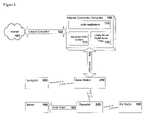
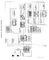
- FIG. 1is a block diagram of the system in accordance with the present invention, shown connected to a host personal computer, which, in turn, is connected to the Internet.
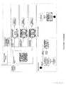
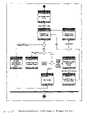
- FIG. 2is a data flow diagram of the base station which forms part of the present invention.
- FIG. 3is a block diagram of the base station which forms a part of this invention.
- FIG. 4is a block diagram of a remote device or navigator which forms a part of the present invention.
- FIG. 5is a is a block diagram of a repeater which forms part of the present invention.
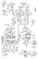
- FIGS. 6-8are schematic diagrams of the base station in accordance with the present invention.
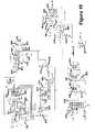
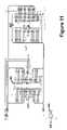
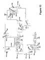
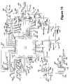
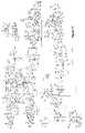
- FIGS. 9-13are schematic diagrams of the remote device in accordance with the present invention.
- FIG. 14is a schematic diagram of the repeater in accordance with the present invention.
- FIGS. 15 and 16are schematic diagrams of a data transceiver in accordance with the present invention.
- FIG. 17is a schematic diagram of an audio transmitter in accordance with the present invention.
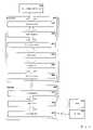
- FIG. 18is a block diagram of the various PC software modules which form the present invention.
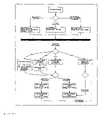
- FIG. 19is a flow diagram for the audio player software module in accordance with the present invention.
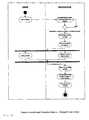
- FIG. 20is a flow diagram for the remote device manager software module in accordance with the present invention.
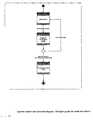
- FIG. 21is a flow diagram of the audio driver software module in accordance with the present invention.
- FIG. 22is a flow diagram of the remote device driver software module in accordance with the present invention.
- FIG. 23is a block diagram of an Internet accessing software module in accordance with the present invention.
- FIG. 24is a block diagram of a basic user interface structure.
- FIG. 25is an exemplary user interaction diagram.
- FIG. 26is an exemplary diagram of a remote device manager in accordance with the present invention.
- FIGS. 27-35are exemplary screen shots for display on the remote device in accordance with the present invention.
- FIGS. 36A and 36Bare block diagrams of the navigator software architecture in accordance with the present invention.
- FIGS. 37-41are scenario oriented user interaction diagrams.
- FIG. 42is a flow diagram of the USB firmware.
- the present inventionis adapted to interface with a host personal computer (PC) which, in turn, is adapted to be connected to virtually any web server in order to obtain audio sources.
- FIG. 1shows the various components in the system and how they interact with one another.
- a host personal computer (PC) 100which may be connected to the Internet which acts as the home audio server.
- the host PC 100is preferably a Pentium or better microprocessor running Windows 95 or better.
- the host PC 100may be controlled to select and play and convert various forms of digital music, for example, from the Internet or from stored digital files for broadcast by remote audio device, such as a stereo or radio, under the control of a remote device or navigator which enables the host PC to run other applications if desired.
- Audio applications 110 running on the Internet connected computer 100receive streaming audio content 111 , such as from Internet radio stations, from the Internet 101 over a network connection 102 , through a modem or network interface card, or use locally stored audio files 112 , such as MP3 encoded audio, and send this digital audio data 220 to the base station 200 , through, for example, a Universal Serial Bus, or USB cable 103 .
- the base station 200decodes the digital audio data 220 , if necessary, and then converts this decoded digital audio data 221 to analog audio signals 222 .
- the base station 200then transmits the analog audio signals 222 to a receiver or repeater 240 .
- the repeater 240provides audio output 104 for connection to an audio playback device, such as a stereo 105 .
- the repeater 240may also be configured to, for example, rebroadcast the audio output 104 onto an unused FM radio channel for reception by a nearby FM radio 106 .
- the userinteracts with the remote device or navigator 260 to communicate wirelessly through the base station 200 with audio applications 110 running on the Internet connected computer 100 in order to change the Internet radio station, select a music playlist, and purchase goods, among other things without interfering with the operation of the host PC 100 .
- FIG. 2diagrams the flow of audio data and the changes this data undergoes as it passes through the various components of the system.
- the Internet connected computer 100sends digital audio data 220 to the base station 200 .
- the digital audio data 220is passed to the audio processor 202 , for example, a Texas Instruments, Model No. TMS320VC5416, for decoding, if the digital audio data 220 is in an encoded format, such as MP3.
- the audio processor 202takes the decoded audio data 221 and passes it to the stereo digital to analog converter, or DAC 207 , for example, a Texas Instrument, Model No. TLC320AS77C, for conversion to analog.
- the stereo DAC 207passes the analog audio 222 to the audio transmitter 209 , which wirelessly transmits the analog audio 222 to the repeater 240 .
- the audio receiver 241for example, as discussed below in connection with FIG. 14 , in the repeater 240 receives the analog audio 222 and provides audio output 104 for connection to a stereo 105 .
- the audio output 104also goes to the FM transmitter 243 , for example, as discussed below in connection with FIG. 14 , for rebroadcast onto an unused FM radio channel for reception by a nearby FM radio 106 .
- FIG. 3shows the various functional hardware blocks within the base station 200 and how the base station 200 interacts with the other components in the system.
- the base station 200may connect to an Internet connected host computer (PC) 100 through a USB cable 103 .
- the USB interface controller 201for example, an (MFR) Model No. TUSB3200, handles communications with the host PC 100 .
- the USB interface controller 201reads the code it runs from the USB firmware ROM 205 described below.
- the USB interface controller 201is responsible for passing digital audio data 220 from the host PC 100 to the audio processor 202 so that the digital audio data 220 can be decoded, if it is in an encoded format, such as MP3.
- the USB interface controller 201also handles data communications between the host PC 100 and the navigator 260 through the data transceiver 211 , which wirelessly transmits and receives the data communications.
- the audio processor 202takes the digital audio data 220 and decodes it, if necessary. It then passes the decoded audio data 221 to the stereo DAC 207 , which converts the decoded audio data 221 to analog audio 222 .
- the analog audio 222passes through some audio filtering 208 before going to the audio transmitter 209 , for example, as discussed below in connection with FIG. 17 , which wirelessly transmits the analog audio 222 to the repeater 240 .
- the audio processor 202reads the code it runs from the DSP firmware ROM 206 .
- FIG. 42outlines the base station USB firmware flow.
- the USB interface controller firmwaredetermines the type of access from the Internet connected computer 100 . If the access type is for transmit data to the navigator 260 , then the USB interface controller firmware writes the data to the data transceiver 211 . The data transceiver 211 then transmits the data to the navigator 260 . The USB interface controller firmware returns acknowledge to the Internet connected computer 100 for the data transmit access to indicate data transmission is complete. If the access type is for receive data from the navigator 260 , then the USB interface controller firmware checks the data transceiver 211 to see if there is any receive data available.
- the USB interface controller firmwareIf there is no receive data available, then the USB interface controller firmware returns no data available to the Internet connected computer 100 . If the data transceiver 211 has receive data available, then the USB interface controller firmware reads the receive data from data transceiver 211 . The USB interface controller firmware then returns the receive data to the Internet connected computer 100 . If the access type is audio data, the USB interface controller firmware passes the audio data directly to the audio processor 202 .
- the unique ID 203allows digital audio data 220 to only be accessible from a particular base station 200 through encoding of the digital audio data 220 based on the unique ID 203 for a particular base station 200 .
- the real-time clock 204allows use of digital audio data 220 to expire based on the current time value in the real-time clock 204 .
- the navigator 260acts as a remote device manager or remote control and allows the user to receive feedback from and provide input to audio applications 110 running the host PC 100 .
- Data communicationspass between the host PC 100 and the navigator 260 through the base station 200 .
- the base station 200is connected to the host PC 100 through a USB cable 103 .
- the base station 200then wirelessly transmits and receives the data communications with the navigator 260 , giving the navigator 260 mobility within the range of the wireless communications.
- FIG. 4illustrates this interaction between the host PC 100 , the base station 200 , and the navigator 260 , as well as outlining the hardware functional blocks within the navigator 260 .
- the navigator 260receives and transmits the data communications using the data transceiver 211 .
- the processor 261( FIG. 9 ), for example, a Motorola Model No. MC68EZ328, handles the data communications with the data transceiver 211 .
- the processor 261takes user input from the user controls 264 , which may be typically buttons and dials, and sends this information to the data transceiver 211 for wireless transmission to the base station 200 and eventually back to the audio applications 110 running on the host (PC) 100 .
- the processor 261receives update information from the audio applications 110 through the data transceiver 211 , which the processor 261 then makes available to the user by updating the graphic information on the liquid crystal display panel, or LCD 266 .
- the processor 261reads the code it runs from the flash memory 263 , which is also used to store information that must survive power cycling of the navigator 260 .
- the processor 261uses random access memory, or RAM 262 , for executing code and storing volatile information, this is information that is subject to change or does not need to survive power cycling of the navigator 260 .
- Additional functionalitymay be provided through the power handler and battery charger 267 , which is controlled by the processor 261 and is responsible for power management, to conserve battery life, and charging of the batteries 268 .
- Theremay also be an infrared or IR transmitter 265 that allows the navigator 260 to control audio playback equipment, such as a stereo 105 .
- the repeater 240( FIG. 5 ) provides fairly straightforward hardware functionality.
- FIG. 5outlines the various functional blocks within the repeater 240 and its interaction with the other components in the system.
- the base station 200wirelessly transmits analog audio 222 for reception by the audio receiver 241 in the repeater 240 .
- the audio receiver 241provides audio output 104 for connection to a stereo 105 .
- the audio output 104also goes to the FM transmitter 243 , which rebroadcasts the audio output 104 onto an unused FM radio channel for reception on a nearby FM radio 106 .
- Radio channel selection for both the audio receiver 241 and the FM transmitter 243is handled by the repeater controller 242 , which receives user inputs from the user controls 244 , such as buttons.
- the user controls 244indicate to the repeater controller 242 the desired user selection of a specific FM radio channel for the FM transmitter 243 to broadcast on.
- the user controlsalso indicate the desire by the user for the audio receiver 241 to scan for transmission from the base station 200 on all defined transmission frequencies.
- FIGS. 6-8represent the schematic design for the base station 200 circuit board implementation example.
- the data transceiver 211 and data antenna 212are part of a separate schematic design and circuit board.
- the data transceiver 211 circuit board moduleconnects both electrically and mechanically to the base station 200 circuit board using the connector 394 on the base station 200 .
- Resistors 392 and 393are for debug purposes and provide easier debug access to the I 2 C bus signals used by the USB interface controller 201 to communicate with the data transceiver 211 .
- the audio transmitter 209 and the audio antenna 210are also part of a separate schematic design and circuit board.
- the audio transmitter 209 circuit board moduleconnects both electrically and mechanically to the base station 200 circuit board using the connector 391 on the base station 200 .
- Devices 209 , 210 , 211 and 212are discussed below in more detail in connection with FIGS. 15-17 .
- a USB cable 103connects from the host PC 100 to the base station 200 using USB connector 380 on the base station 200 . Signals from the USB connector 380 then go to the USB interface controller 201 .
- the USB interface controller 201 in this exampleis, for example, Texas Instruments Model No. TUSB3200. Resistors 378 , 379 , and 381 and capacitors 382 and 383 provide the proper loading and electrostatic protection on the USB signals from the USB connector 380 . Capacitors 361 , 362 , 363 , 364 , 365 , 376 , and 377 provide filtering for the power to the USB interface controller 201 .
- a supply voltage supervisor 356such as the Texas Instruments TPS3809, provides software controlled reset of the USB interface controller 201 , a feature useful after completing an update of the USB firmware ROM 205 .
- Resistors 352 and 355 , capacitor 354 , and transistor 353complete implementation of the software controlled reset.
- Resistor 357is used to provide easier access to the reset signal from the supply voltage supervisor 356 for debug.
- Oscillator 373provides the clock for the USB interface controller 201 and capacitors 374 and 375 provide the loading required by the oscillator 373 .
- Resistor 358 and capacitors 359 and 360provide filtering for the phase locked loop, or PLL, inside the USB interface controller 201 that is used to generate additional clock signals.
- Resistor 389reduces noise on the master clock signal MCLK from the USB interface controller 201 to the DAC 207 .
- Resistors 366 , 368 , 369 , 370 , 384 , and 387provide pull-ups to power or pull-downs to ground for various signals on the USB interface controller 201 .
- Resistors 385 , 386 , and 388provide easier access to various signals on the USB interface controller 201 for debug and the headers 367 , 371 , and 372 provide easy connection and disconnection of signals on the USB interface controller 201 for debug.
- the USB interface controller 201reads the code it executes from USB firmware read only memory, or ROM, 205 .
- ROMfirmware read only memory
- One 256 kilobit serial ROMis used for the design implementation.
- the design implementationsupports two different packaging sizes for the serial ROMs, so either serial ROM 477 or 478 is included.
- Resistors 479 , 480 , 481 , and 482act as pull-ups to power or pull-downs to ground for various signals to the serial ROMs 477 and 478 .
- Resistors 483 and 484are for debug purposes and provide easier debug access to the I 2 C bus signals used by the USB interface controller 201 to communicate with the serial ROMs 477 and 478 .
- Bypass capacitor 510provides filtering for power to the serial ROMs 477 and 478 .
- the audio processor 202 in this exampleis the Texas Instruments digital signal processor, or DSP, TMS320VC5416.
- the bypass capacitors 300 , 301 , 302 , 303 , 304 , 305 , 306 , 307 , 308 , 309 , 310 , 311 , and 312provide filtering on the interface and core power supplied to the audio processor 202 from the dual output voltage regulator 494 .
- Resistors 313 , 314 , 319 , 320 , 321 , 322 , 323 , 324 , 325 , 326 , 327 , 328 , and 329are used as pull-ups to power or pull-downs to ground for various signals on the audio processor 202 .
- Resistors 330 , 331 , 332 , 333 , 334 , 335 , 336 , 337 , 338 , 339 , 340 , 341 , 342 , and 343have no impedance and simply provide better debug access to the various signals going to and coming from the audio processor 202 .
- Resistors 330 , 331 , 334 , 335 , 336 , 337 , 341 , and 343also allow for the selection of access to signals from one port or another on the audio processor 202 , providing additional flexibility during debug of the design.
- Inverter 316provides voltage level shifting of the clock signal to the audio processor 202 , while resistor 317 allows the voltage level shifting to be bypassed if it is not needed. Inverter 316 and resistor 317 , therefore, are mutually exclusive with only one or the other being placed on the circuit board. Capacitor 315 provides bypass capacitance on the power for the inverter 316 .
- the audio processor 202reads the code it executes from DSP firmware read only memory, or ROM, 206 . Two 512 kilobit serial ROMs are used for the design implementation. The design implementation supports two different packaging sizes for the serial ROMs, so either serial ROMs 461 and 469 are included or 462 and 470 are included.
- Resistors 463 , 464 , 465 , 466 , 471 , 472 , 473 , and 474act as pull-ups to power or pull-downs to ground for various signals on the serial ROMs 461 , 462 , 469 , and 470 .
- Resistors 467 , 468 , 475 , and 476are for debug purposes and provide easier debug access to the I 2 C bus signals used by the audio processor 202 to communicate with the serial ROMs 461 , 462 , 469 , and 470 .
- Bypass capacitors 506 and 507provide filtering for power to the serial ROMs 461 , 462 , 469 , and 470 .
- the digital to analog converter, or DAC, 207is implemented in this example using the Texas Instruments TLC320AD77C.
- Power filtering, as well as filtering of the common voltage to the amplifiers 437 and 451is handled by the capacitors 399 , 400 , 401 , 402 , 508 , and 509 .
- Filtering for the DAC reference voltageis provided by the capacitors 403 , 404 , 405 , 406 , and 407 .
- Resistors 395 , 396 , 397 , 398 , 408 , 409 , and 410provide pull-ups to power or pull-downs to ground for various signals on the DAC 207 .
- the analog audio 222 from the DAC 207goes through filtering circuitry that provides a frequency band pass from roughly 20 Hz to 20,000 Hz.
- This band pass filtering circuitryis comprised of operational amplifiers, or op amps, 429 , 437 , and 451 , resistors 425 , 426 , 431 , 433 , 438 , 441 , 443 , 444 , 446 , 448 , 450 , 452 , 455 , 457 , 458 , and 512 , and capacitors 427 , 428 , 430 , 432 , 439 , 440 , 442 , 445 , 447 , 449 , 453 , 454 , 456 , and 511 .
- the filtered audiogoes to the audio transmitter 209 as well as to line level output connector 459 .
- the inductor 434 and the capacitors 435 and 436provide filtering on the power to the op amps 429 , 437 , and 451 .
- An external 9 to 12 volt power supplyprovides all power to the base station 200 and connects to the base station 200 through the power jack 485 .
- Diode 486provides a voltage drop and reverse polarity protection for the external power supply.
- Capacitor 487provides filtering on the power from the external power supply. Since there are various voltage levels required in this specific implementation, there are multiple levels of voltage regulation.
- Voltage regulator 488converts the voltage from the external power supply voltage to 5 volts.
- Light emitting diode, or LED, 490provides visual feedback to the user that the base station 200 is successfully powered. Resistor 489 provides additional loading for the LED 490 , to reduce the current going through the LED 490 .
- Bypass capacitor 491provides filtering on the 5-volt power from the voltage regulator 488 .
- a dual output voltage regulator 494which in this example is a Texas Instruments TPS70148, provides these two voltage levels.
- Capacitors 499 , 500 , 504 , and 505provide filtering on the power outputs from the dual output voltage regulator 494 .
- Resistors 495 , 496 , and 497are for debug purposes and allow removal of 3.3-volt power to different sections in the design.
- Resistors 492 , 493 , and 498act as pull-ups to power or pull-downs to ground for various signals on the dual output voltage regulator 494 .
- Ferrite beads 501 , 502 , and 503provide noise filtering and isolation between the various ground planes in the base station 200 circuit board.
- the unique ID 203is implemented this example using the Dallas Semiconductor DS2401.
- the unique ID 203has a single pin serial interface that can be connected to the USB interface controller 201 through the resistor 411 or to the audio processor 202 through the resistor 412 .
- the real-time clock 204is implemented in this example using the Philips Semiconductor PCF8563.
- the real-time clock 204communicates on the I 2 C bus with the USB interface controller 201 , with resistors 421 and 422 providing easier debug access to the I 2 C bus clock and data signals.
- Power to the real-time clock 204is normally provided from the 5-volt regulator 488 . When the external power supply is not available, the battery 416 provides power to the real-time clock 204 in order to maintain the correct time.
- Diode 418prevents the 5-volt power from charging the battery 416 and diode 419 prevents the current from the battery 416 from leaking into the 5-volt power circuit.
- Resistor 417provides additional loading in case the diode 418 fails.
- Bypass capacitor 420provides filtering on the power to the real-time clock 204 .
- Oscillator 423provides a timing count for the real-time clock 204 , while the capacitor 424 provides a load as required by the oscillator 423 .
- Connector 349is used for connection to an external JTAG emulator.
- the JTAG interfaceconnects to the audio processor 202 and is used for debugging of code running on the audio processor 202 .
- Resistors 348 , 350 , and 351are used to pull-up to power or pull-down to ground certain signals on connector 349 that go to the audio processor 202 in case the JTAG emulator is not connected.
- the connector 349will be removed for production.
- Connector 390is used for connection to an external 8051 emulator.
- the 8051 emulation interfaceconnects to the USB interface controller 201 and is used for debugging of code running on the USB interface controller 201 .
- the connector 390is not used for production.
- Connector 415provides easy debug access to the clock and data signals on the I 2 C bus, which is used by the USB interface controller 201 or audio processor 202 to access peripherals such as the real-time clock 204 , USB firmware ROM 205 , and DSP firmware ROM 206 . Connector 415 will be removed for production. Resistors 413 and 414 are used as pull-ups to power for the I 2 C bus clock and data signals. Inverters 344 , 345 , 346 , and 347 are not used, but are within a part that is being used. op amp 460 is not used, but is within a part that is being used. Resistor 318 is not used and is not placed on the circuit board.
- FIGS. 9 through 13represent the schematic design for the navigator 260 circuit board implementation example.
- the data transceiver 211 and data antenna 212are part of a separate schematic design and circuit board.
- the data transceiver 211 circuit board moduleconnects both electrically and mechanically to the navigator 260 circuit board using the connector 648 on the navigator 260 .
- Capacitor 647 on the navigator 260provides additional filtering on the power supplied to the data transceiver 211 circuit board module.
- Control of the navigator 260rests in the processor 261 , which in this example is implemented with a Motorola MC68EZ328.
- the processor 261interprets the input from the user controls 264 and sends this information back to the host PC 100 through the data transceiver 211 .
- the processor 261also receives and interprets display update information from audio applications 110 running on the Internet connected computer 100 from the data transceiver 211 .
- the display informationis sent to the liquid crystal display panel, or LCD, 266 , which connects to the navigator 260 circuit board using the connector 688 on the navigator 260 .
- Capacitors 686 and 687filter power going to the LCD 266 on the connector 688 .
- the processor 261may control an infrared LED, or IR transmitter 265 , for example, a LumEx, Model No. OED-CL-1556SN, that is used to control audio playback devices, such as a stereo 105 , that supports infrared control.
- Transistor 615acts as a switch based on a signal from the processor 261 to enable and disable the IR transmitter 265 and the resistor 617 provides additional load to limit the amount of current to the IR transmitter 265 .
- Another LED 619indicates to the user that the navigator 260 is successfully powered.
- Transistor 618acts as a switch based on a signal from the processor 261 to enable and disable the LED 619 and the resistor 620 provides additional load to limit the amount of current to the LED 619 .
- Oscillator 603provides timing to the processor, while capacitors 601 and 602 provide loading required by the oscillator 603 .
- the reset signal of the processor 261which is responsible for resetting the processor 261 , is enabled when power is first applied to the processor 261 through a delay circuit composed of resistor 612 and capacitor 613 .
- the button 614also resets the processor 261 and is included for debug purposes.
- Capacitors 604 , 606 , and 607 along with resistor 605provide filtering for the power to the phase locked loop, or PLL, circuitry within the processor 261 that is used to generate additional timing within the processor 261 .
- Resistor 600acts as a pull-up to power for a signal on the processor 261 .
- the processor 261uses external random access memory, or RAM, 262 , which can come in a 4 megabyte by 16-bit configuration, for executing code and for storing information that doesn't need to survive a power down of the navigator 260 .
- the processor 261also uses external flash memory 263 , which can come in a 1 megabyte by 16-bit configuration, for storing the code to be executed as well as storing information that must survive a power down of the navigator 260 .
- the capacitors 667 and 668provide filtering for the power to the RAM 262 and flash memory 263 .
- the user controls 264may be composed of a set of 16 buttons 669 , 670 , 671 , 672 , 674 , 675 , 676 , 677 , 678 , 679 , 680 , 681 , 682 , 683 , 684 , and 685 ( FIG. 12 ), which may be arranged in a 4 ⁇ 4 array and scanned by the processor 261 . This reduces the number of signals required on the processor 261 to support the user controls 264 .
- Capacitors 608 , 609 , 610 , and 611act to reduce voltage spikes on the return signals from the user controls 264 to the processor 261 when the user controls 264 are activated and deactivated.
- Button 671may be used to turn power on to the entire navigator 260 .
- the button 671is always powered, even when power is turned off to the rest of the navigator 260 .
- Diode 673prevents current leakage from button 671 when the rest of the navigator 260 is turned off.
- the 3.3-volt regulator 630provides power to the button 671 as well as a flip-flop 635 that is also always on to receive the power on signal from the button 671 .
- Capacitors 629 , 631 , and 632provide filtering for power to the always on button 671 and flip-flop 635 .
- Resistors 633 and 634act as pull-ups to power for signals to the flip-flop 635 .
- Resistor 637 and transistor 636work together with flip-flop 635 to control the shut down of the 3.3-volt switcher 640 that provides power to the rest of the navigator 260 .
- Capacitors 638 , 639 , 642 , and 643provide filtering for power to and from the switcher 640 .
- Inductor 641completes a feedback circuit required by the switcher 640 .
- Resistor 645 and capacitors 644 and 646provide external compensation circuitry also required by the switcher 640 .
- the battery 268provides power to the navigator 260 and connects to the navigator 260 through the connector 590 on the navigator 260 .
- Diodes 588 , and 589 , transistor 585 , and resistors 586 and 587provide over-voltage protection from the battery 268 and also protect against the battery 268 being plugged incorrectly into the connector 590 . This protection can be bypassed by including resistor 584 .
- the navigator 260supports recharging of the battery 268 through a battery charger 267 .
- the battery charger 267is composed of a battery charge controller 699 , which in this example is a Maxim Integrated Products MAX712CSE, along with the required support circuitry.
- the support circuitry required by the battery charge controller 699is composed of diode 689 , transistor 694 , resistors 691 , 693 , 696 , and 697 , and capacitors 577 , 583 , 690 , 692 , 695 , and 698 .
- Resistors 579 , 580 and 582 and transistors 578 and 581detect if the battery 268 is rechargeable and provide this signal to the battery charge controller 699 to prevent the battery charger 267 from trying to charge a non-rechargeable battery 268 .
- the analog to digital converter 599for example, a (MFR) Model No. LTC1285C58 along with diode 596 , capacitors 593 and 598 , and resistors 591 , 592 , 594 , 595 , and 597 are used by the processor 261 to monitor the battery 268 voltage level for calculating battery life and controlling battery charging.
- the processor 261can individually control power to the data transceiver 211 and the LCD 266 as part of power management to increase battery life on the navigator 260 .
- the processor 261is able to control the voltage level for the contrast power supplied to the LCD 266 , which allows user control of display contrast. To do this, the processor 261 adjusts a digital potentiometer 660 , for example, a Dallas Semiconductor Model No. DS1869-S-010, which outputs a variable voltage level based on a voltage divider circuit made up of resistors 658 and 659 . This variable voltage level feeds a DC to DC converter 666 , which takes this voltage level as an input to determine the contrast supply voltage level that is output to the LCD 266 . Resistor 665 , inductor 663 , and diode 662 fulfill requirements of the DC to DC converter 666 . Capacitors 661 and 664 provide filtering for the contrast power supply to the LCD 266 .
- a digital potentiometer 660for example, a Dallas Semiconductor Model No. DS1869-S-010, which outputs a variable voltage level based on a voltage divider circuit made up of
- Connector 621is used for debug access to the processor 261 .
- the debug portis implemented as an industry standard RS-232 serial port.
- the RS-232 interface controller 626for example a Sipex Corp., Model No. SP385ACA, handles the required RS232 interface level conversions.
- Capacitors 622 , 623 , 624 , 625 , and 628provide filtering for power for the various voltage levels used by the RS-232 interface controller 626 .
- Resistor 627acts as a pull-up to power for the ON signal to the RS-232 interface controller 626 .
- processor 261 debug port components 621 , 622 , 623 , 624 , 625 , 626 , 627 , and 628are included for production.
- the flip-flop 657is unused.
- Resistor 656is used to pull-up to power the inputs of the unused flip-flop 657 .
- FIG. 14represents the schematic design for the repeater 240 circuit board implementation example.
- the repeater 240is composed of four sections, the repeater controller 242 , the user controls 244 , the audio receiver 241 , and the FM transmitter 243 .
- the repeater controller 242which in this example is a Microchip PIC16C57, interprets the selections for the user controls 244 .
- Switch 1029selects the FM transmission frequency, with resistors 859 , 860 , 861 , and 862 acting as pull-downs to ground for the switch 1029 selections.
- Switch 845signals that the audio receiver 241 should scan through the audio transmission frequencies for a wireless audio transmission signal from the base station 200 to lock to.
- Resistor 846acts as a pull-up to power for the switch 845 .
- LEDs 839 and 840signal to the user the status of receiving an audio transmission from a base station 200 by the audio receiver 241 on the repeater 240 .
- Resistor 841provides additional loading to limit the current to the LEDs 839 and 840
- resistor 842acts as a pull-up to power for the status signal that controls the LEDs 839 and 840 .
- Voltage detector 853for example, a Telcom, Model No. TC54VC2702ECB, generates the reset signal to the repeater controller 242 to reset the repeater controller 242 .
- Oscillator 851provides the timing for the repeater controller 242 .
- Capacitors 850 and 852 and variable capacitor 849provide the required loading for the oscillator 851 .
- Capacitor 844provides filtering for power to the repeater controller 242 .
- Wireless audio transmissions from the base station 200come to the repeater 240 through the audio antenna 700 , for example, a 22AWG solid wire, on the repeater 240 .
- the audio signalfirst passes through SAW filter 701 , for example, a Murata Model No. SAFC927MF9OT-TC12, which acts as a band pass filter.
- the signalthen feeds into the low noise amplifier, or LNA, and down converter mixer 710 , which in this example is a Maxim Integrated Products MAX2685.
- the LNA and down converter mixer 710down converts the audio signal for use by the FM stereo receiver and decoder 733 .
- Capacitors 702 and 703 and inductor 704provide impedance matching of the signal to the input of the LNA inside the LNA and down converter mixer 710 .
- Capacitors 711 and 713 and inductor 712provide impedance matching from the output of the LNA inside the LNA and down converter mixer 710 to the input of the mixer, also inside the LNA and down converter mixer 710 .
- the down converted audio output signal from the LNA and down converter mixer 710then passes through an impedance matching and filtering circuit composed of the capacitors 716 , 717 , 719 , 720 , 721 , 723 , and 724 , resistor 714 , and inductors 715 , 718 , and 722 .
- Capacitors 705 , 706 , 709provide filtering for power to the LNA and down converter mixer 710 .
- the local oscillator used by the LNA and down converter mixer 710comes from the voltage controlled oscillator, or VCO.
- the VCO circuitis composed of resistors 708 , 892 , 901 , 908 , 911 , 914 , 915 , and 916 , capacitors 707 , 891 , 893 , 895 , 896 , 897 , 898 , 899 , 900 , 907 , 909 , 910 , 912 , and 913 , varactor 890 , inductor 906 , ceramic resonator 894 , and RF oscillator 904 .
- Resistor 903 and capacitors 902 and 905provide filtering for power to the RF oscillator 904 .
- the frequency synthesizer 877which in this example is a National Semiconductor LMX2316TM, controls the VCO circuit.
- the repeater controller 242selects the frequency of the frequency synthesizer 877 through a serial interface with the frequency synthesizer 877 , for example, a National Semiconductor, Model No. LMX 2316TM.
- the repeater controller 242also provides the reference frequency for the frequency synthesizer 877 from the oscillator 851 .
- the reference frequencyis filtered by capacitor 855 before going to the frequency synthesizer 877 .
- Resistors 868 , 875 , 876 , and 887 and capacitors 869 , 870 , 871 , 874 , 888 , and 889provide additional support for the frequency synthesizer 877 .
- Resistors 881 , 883 , and 886 , capacitor 884 , and transistor 885act as a frequency synthesis PLL lock detect circuit to provide PLL lock detection feedback to the repeater controller 242 when receive frequency changes are made.
- Transistor 866 , capacitors 864 and 878 , and resistors 863 , 865 , 867 , and 879provide filtering for power to the charge pump inside the frequency synthesizer 877 .
- Resistors 872 and 880 and capacitors 873 and 882provide filtering for digital power to the frequency synthesizer 877 .
- the down converted audio signalthen goes to the FM tuner 733 , which in this example is a Toshiba TA8122.
- the FM tuner 733does the multiplexed decoding and a final level of down conversion of the audio signal to base band.
- Oscillator 744along with resistors 737 , 740 , and 743 , capacitors 735 , 736 , 738 , 741 , and 742 , transistor 739 , and inductor 734 provide the reference timing for the down conversion handled in the FM tuner 733 .
- Oscillator 731provides the reference frequency for the FM stereo decoding handled in the FM tuner 733 .
- Oscillator 732provides the reference frequency to the FM tuner 733 for synchronization with the pilot tone in the audio signal.
- Resistors 728 , 762 , 765 , and 1043 , capacitors 726 , 727 , 729 , 730 , 761 , 763 , 764 , 766 , 767 , 768 , and 769 , inductor 760 , and ceramic filter 725provide additional support for the FM tuner 733 .
- Resistors 848 and 856 and transistor 857allows the repeater controller 242 to force the FM tuner 733 to output mono instead of stereo, however, the FM tuner 733 normally outputs stereo audio signals.
- the stereo audio signals output from the FM tuner 733first pass through a pilot trap filter to remove the pilot tone from the stereo audio signals.
- the pilot trap filteris composed of capacitors 745 , 746 , 748 , 770 , 772 , and 773 , and variable inductors 747 and 771 .
- the stereo audio signalsthen pass through a gain control circuit, which is composed of resistors 750 , 752 , 753 , 775 , 776 , 777 , 779 , and 780 , variable resistors 754 and 782 , capacitors 749 , 774 , and 778 , and op amps 751 and 781 .
- the stereo audio signalsthen pass through a de-emphasis circuit to restore the high frequencies in the signals.
- Resistors 755 and 783 , capacitors 756 and 784 , and op amps 757 and 785make up the de-emphasis circuit.
- Capacitors 758 and 759provide power filtering for the op amps 751 , 757 , 781 , and 785 .
- the stereo audio signalsnext pass through a dynamic range decompression circuit to match the compression done in the audio transmitter 209 in the base station 200 .
- the compandor 794which in this example is a Philips Semiconductor SA572, is configured to operate for decompression.
- Resistors 805 and 838provide an option to bypass the decompression circuit.
- Capacitors 806 and 807provide filtering for power to the compandor 794 .
- Resistors 816 and 823 and capacitors 817 and 824provide final filtering on the stereo audio signals before the stereo audio signals are output on the connectors 818 and 825 .
- Resistor 822 , diode 843 , and transistors 819 and 820act as a mute control circuit for use by the repeater controller 242 to mute the stereo audio output signals.
- the stereo audio output signalsare also passed from the audio receiver 241 to the FM transmitter 243 , also on the repeater 240 , for broadcast.
- the stereo audio signalspass through a gain circuit, which is composed of resistors 926 , 928 , 929 , 930 , 931 , 933 , 934 , and 935 and capacitors 927 and 932 .
- the stereo audio signalspass through a pre-emphasis circuit to boost the high frequencies in the signals.
- Resistors 936 , 937 , 939 , 940 , 942 , and 944 and capacitors 938 , 941 , 943 , and 945make up the pre-emphasis circuit.
- the audio signalsgo to the stereo modulator encoder 950 , for example, a New Japan Radio Corp., Model No. NJM2035M, which handles the stereo encoding process that involves time division multiplexing of the stereo audio signals.
- a multiplexing circuitsupports the stereo modulator encoder 950 .
- the multiplexing circuitis composed of resistors 951 , 952 , and 953 and capacitors 954 and 955 .
- Capacitors 946 and 947provide additional support to the stereo modulator encoder 950 .
- the multiplexed audio signalcomes from the stereo modulator encoder 950 and passes through a low pass filter circuit.
- the low pass filter circuitis made up of resistor 956 , capacitors 962 , 964 , 965 , 966 , and 969 , and variable inductor 963 .
- the multiplexed audio signalthen goes to a summing circuit where the multiplexed audio signal is summed with the pilot tone.
- Oscillator 948supported by capacitor 949 , provides the timing for the generation of the pilot tone, which is required for FM radio broadcast.
- the pilot tonecomes from the stereo modulator encoder 950 and passes through a pilot filter, composed of resistors 958 and 972 , capacitors 957 , 960 , and 961 , and variable inductor 959 .
- the pilot toneis then goes to a summing circuit where the pilot tone is summed with the multiplexed audio signal.
- the summing circuitis composed of resistors 971 , 973 , 974 , 976 , 978 , and 980 , capacitor 979 , and transistors 975 and 977 .
- Resistor 967 and capacitors 968 and 970provide power filtering for the summing circuit.
- the summed audio signalmodulates the voltage controlled oscillator, or VCO, circuit to generate the FM radio signal.
- the VCO circuitis made up of resistors 986 , 987 , 989 , 990 , 991 , 1001 , 1003 , 1004 , and 1010 , capacitors 985 , 988 , 993 , 998 , 1002 , 1011 , 1013 , 1014 , 1016 , and 1017 , inductors 996 and 1005 , varactor 992 , and transistors 1009 and 1012 .
- Resistor 1006 and capacitors 1007 and 1008provide filtering for power to the VCO circuit.
- the VCOis controlled by the phase locked loop, or PLL, which is inside the frequency synthesizer 995 .
- the frequency synthesizer 995 in this exampleis the National Semiconductor LMX1601.
- the repeater controller 242provides the reference frequency for the frequency synthesizer 995 through the inverter 854 and filtering capacitor 981 .
- Capacitor 858provides power filtering for the inverter 854 .
- Resistors 982 and 1000 and capacitors 983 , 984 , and 999provide power filtering for the frequency synthesizer 995 .
- Resistor 997acts as a pull-up to power to the enable signal on the frequency synthesizer 995 .
- Capacitor 994provides filtering on an unused output from the frequency synthesizer 995 .
- the frequency modulated signalgoes from the VCO circuit to an output gain adjustment circuit, that affects the output power of the transmission.
- the output gain adjustment circuitis made up of resistors 1015 , 1018 , 1019 , 1020 , 1021 , 1022 , and 1024 and capacitor 1025 .
- the frequency modulated signalpasses through a pi filter circuit, which is responsible for removing harmonics from the transmission signal, before going to the FM transmitter antenna 1027 for broadcast to a nearby FM radio 106 .
- the pi filter circuitis made up of capacitors 1023 and 1028 and inductor 1026 .
- Power to the repeater 240comes from an external 12-volt unregulated power supply.
- the external power supplyconnects to the repeater 240 circuit board using connector 1030 on the repeater 240 .
- Diode 1031provides protection for the repeater 240 in case an incorrect power supply is plugged into the repeater 240 on connector 1030 .
- the 12-volt unregulated powerfeeds into voltage regulator 1034 .
- Capacitors 1032 and 1033provide filtering for the 12-volt input to the regulator 1034 .
- Capacitors 1035 and 1039 and resistor 1036provide filtering for the 3.3-volt output from the regulator 1034 .
- Resistors 1037 and 1038provide the output voltage selection for the regulator 1034 .
- the 12-volt unregulated poweralso feeds into regulator 924 to provide 10-volt power to the audio receiver 241 .
- Capacitor 925provides filtering for the 12-volt input to the regulator 924 , while capacitor 923 provides filtering for 10-volt output from the regulator 924 .
- Resistors 921 and 922provide the output voltage selection for the regulator 924 .
- Additional 3-volt poweris supplied by regulator 918 , with capacitor 917 acting as filter for input power, capacitor 920 acting as a filter for output power and capacitor 919 providing bypass support for the regulator 918 .
- Regulator 1040supplies power to the FM transmitter 243 .
- the repeater controller 242controls output from the regulator 1040 , so the FM transmitter 243 can be selectively powered down.
- Capacitor 1041provides is filtering for the power output from the regulator 1040 and capacitor 1042 provides the required bypass support for the regulator 1040 .
- FIGS. 15 and 16represent the schematic design for the data transceiver 211 circuit board implementation example, which connects to the navigator 260 or the base station 200 using connector 1198 on the data transceiver 211 .
- the data controller 1215which in this example is a Microchip PIC17C756, and the RF transceiver 1170 , which in this example is a Texas Instruments TRF6900.
- the data controller 1215handles communications with the navigator 260 or the base station 200 through a serial interface on connector 1198 on the data transceiver 211 .
- the data controller 1215is also responsible for controlling the RF transceiver 1170 for such things as frequency channel selection.
- the data controller 1215also buffers the transmit data to the RF transceiver 1170 and receive data from the RF transceiver 1170 .
- the RF transceiver 1170acts as the radio transmitter and receiver for the data transceiver 211 for wireless data communications with another data transceiver 211 .
- Signals on the connector 1198are defined to operate at 3.3 volts.
- the data controller 1215which interfaces with the connector 1198 , operates at 5 volts.
- level shifting circuitsare used. Resistors 1245 , 1246 , 1247 , 1248 , 1252 , 1253 , 1254 , 1255 , 1256 , 1257 , 1258 , 1259 , 1260 , 1261 , 1262 , 1263 , 1264 , and 1265 act as voltage dividers on outputs from the data controller 1215 .
- XOR gates 1249 , 1267 , 1286 , and 1288act as level shifters for inputs to the data controller 1215 .
- Resistors 1250 , 1251 , 1268 , 1284 , and 1285provide pull-ups to power and pull-downs to ground for the XOR gates 1249 , 1267 , 1286 , and 1288 .
- Capacitor 1266provides filtering for power to the XOR gates 1249 , 1267 , 1286 , and 1288 .
- Resistors 1269 , 1281 , 1287 , and 1289provide selection of SPI or I 2 C communications between the data controller 1215 on the data transceiver 211 and the base station 200 or the navigator 260 .
- Buffer 1283allows the serial data output signal from the data controller 1215 to the connector 1198 to be tri-stated.
- Capacitor 1282provides filtering for power to the buffer 1283 .
- Diode 1217 , resistor 1218 , and capacitor 1219provide the reset signal to the data controller 1215 .
- the RF transceiver 1170provides a radio signal strength signal to the data controller 1215 to indicate if another data transceiver 211 has been detected.
- the resistor 1223 and capacitor 1224support the radio signal strength signal.
- the resistors 1240 and 1242 and variable resistor 1241provide an adjustable threshold voltage for the radio signal strength detection on the data controller 1215 .
- Buffer 1271 and resistors 1272 and 1273support lock detection of the phase locked loop, or PLL, on the RF transceiver 1170 by the data controller 1215 . This lock detection indicates when the RF transceiver 1170 has successfully completed a frequency channel selection.
- Capacitor 1270provides power filtering for the buffer 1271 .
- Oscillator 1276provides the timing for the data controller 1215 , with capacitors 1275 and 1277 and resistor 1274 providing the required loading and impedance for the oscillator 1276 .
- Resistors 1220 , and 1280provide pull downs to ground for signals to the data controller 1215 .
- Capacitors 1216 , 1221 , 1222 , 1243 , 1244 , 1278 , and 1279provide filtering for power to the data controller 1215 .
- Wireless data communicationscome into and go out of the data transceiver 211 through the data antenna 212 .
- the switch 1115controlled by the RF transceiver 1170 , selects between the outgoing transmit signal to the antenna and the incoming receive signal from the antenna.
- Buffer 1103 , resistors 1101 , 1104 , and 1105 , and capacitors 1100 , 1102 , 1106 , and 1107support the selection of the switch 1115 by the RF transceiver 1170 .
- Inductor 1113 and capacitors 1110 , 1111 , 1112 , and 1114act as a low pass filter to suppress harmonics on the transmission signal.
- SAW filter 1109acts as band pass filter.
- Capacitor 1108provides AC coupling of the signal.
- the receive output from the switch 1115feeds the low noise amplifier, or LNA, inside the RF transceiver 1170 .
- the inductor 1137 and capacitors 1134 , 1135 , 1136 , and 1138provide impedance matching for the receive signal to the input of the LNA inside the RF transceiver 1170 .
- the resistor 1117 , inductors 1119 and 1121 , and capacitors 1116 , 1118 , and 1120provide impedance matching for the output of the LNA inside the RF transceiver 1170 to the RF mixer input inside the RF transceiver 1170 .
- Capacitor 1128provides AC coupling and filter 1129 acts as a band pass filter on the output from the RF mixer inside the RF transceiver 1170 .
- Resistor 1174 , inductor 1171 , and capacitors 1172 and 1173act as a frequency shift keying, or FSK, demodulator to demodulate the receive data from the receive signal after it has passed through the band pass filter 1129 .
- Capacitor 1130provides a reference voltage for the demodulator circuit. Next, the demodulated receive data passes through a low pass filter composed of the resistor 1176 and capacitors 1175 and 1177 .
- the receive datagoes through a data slicer inside the RF transceiver 1170 before being sent to the data controller 1215 , where the receive data is buffered before being read by the navigator 260 or base station 200 .
- Capacitor 1178helps provide sample and hold timing for the data slicer inside the RF transceiver 1170 .
- Transmit data to the RF transceiver 1170comes from the data controller 1215 .
- Resistors 1168 and 1169act to modulate the voltage controlled oscillator, or VCO, circuit based on the transmit data.
- the VCO circuitis composed of the resistors 1156 and 1160 , capacitors 1162 , 1163 , 1165 , and 1167 , varactors 1161 and 1166 and inductor 1164 .
- the VCOis controlled by the phase locked loop, or PLL, which is inside the RF transceiver 1170 .
- Resistors 1149 , 1151 , 1152 , and 1154 and capacitors 1150 , 1153 , and 1155provide filtering for the PLL.
- Resistor 1148sets the charge pump current for the PLL.
- the modulated transmit signalthen goes through a power amplifier inside the RF transceiver 1170 , before leaving the RF transmitter 1170 .
- the inductor 1142 and the capacitors 1144 , 1145 , 1146 , and 1147provide impedance matching for the transmit signal to the input of the switch 1115 from the power amplifier inside the RF transceiver 1170 .
- the oscillator 1191provides the reference timing for the RF transceiver.
- Capacitors 1190 and 1192 , variable capacitor 1189 , and resistors 1187 and 1188provide the required loading and impedance for the oscillator 1191 .
- the RF transceiver 1170requires additional filtering for power.
- Capacitors 1122 , 1124 , 1125 , 1127 , 1131 , 1133 , 1139 , 1140 , 1143 , 1157 , 1159 , 1179 , 1181 , 1184 , and 1186 and resistors 1123 , 1126 , 1132 , 1141 , 1158 , 1180 , and 1185provide power filtering for the RF transceiver 1170 .
- Power for the data transceiver 211 from the connector 1198is defined as being 3.3 volts. Since most of the digital circuitry on the data transceiver 211 requires 5 volts, the 3.3-volt to 5-volt step-up converter 1234 is used to step-up the power voltage from 3.3 volts to 5 volts. Inductor 1238 , resistor 1233 , and capacitors 1235 , 1236 , 1237 , and 1239 are required by the step-up converter 1234 to support the step-up converter 1234 functionality.
- the radio circuitryhas an independent power source from the digital circuitry on the data transceiver 211 .
- Voltage regulator 1227for example, a National Semiconductor Model No.
- LP29851M5provides the radio power, with resistor 1226 and capacitors 1225 , 1228 , and 1229 providing required support for the voltage regulator 1227 .
- the data controller 1215is able to control power to the radio circuitry through enabling and disabling the voltage regulator 1227 output.
- Capacitor 1231 and resistors 1230 and 1232support the control of the power to the radio circuitry by the data controller 1215 .
- Resistor 1194has no impedance and simply provides better debug access to the transmit data signal from the data controller 1215 .
- Switches 1202 and 1210 and resistors 1203 , 1204 , 1205 , 1211 , 1212 , 1213 , and 1214provide manual selection of the transmit and receive channel as well as setting test modes for debug purposes and are not included for production.
- LEDs 1207 and 1209provide visual feedback for debug purposes and are not included for production.
- Resistors 1206 and 1208provide additional loading for the LEDs 1207 and 1209 to limit the current going through the LEDs 1207 and 1209 .
- Resistors 1182 , 1183 and 1193are for debug purposes and are not included for production.
- Capacitors 1195 , 1196 , 1197 , 1199 , 1200 , and 1201are for debug and test purposes and are not included for production.
- FIG. 17represents the schematic design for the audio transmitter 209 circuit board implementation example, which connects to the base station 200 using connector 1464 on the audio transmitter 209 .
- the base station 200sets the transmission frequency of the audio transmitter 209 through a serial interface with the frequency synthesizer 1498 , which in this example is a National Semiconductor LMX2316, on the audio transmitter 209 .
- Oscillator 1473along with resistors 1470 , 1471 , 1476 , and 1477 , capacitors 1472 , 1474 , 1479 , and 1487 , variable capacitor 1475 , and buffers 1478 and 1480 provide the reference frequency to the frequency synthesizer 1498 .
- Resistors 1482 , 1489 , 1490 , and 1501 and capacitors 1481 , 1483 , 1484 , 1488 , 1502 , and 1503provide additional support for the frequency synthesizer 1498 .
- Resistors 1465 , 1466 , and 1469 , capacitor 1467 , and transistor 1468act as a frequency synthesis PLL lock detect circuit to provide PLL lock detection feedback to the base station 200 when transmission frequency changes are made.
- Transistor 1494 , capacitors 1491 and 1497 , and resistors 1492 , 1493 , 1495 , and 1496provide filtering for power to the charge pump inside the frequency synthesizer 1498 .
- Resistors 1485 and 1499 and capacitors 1486 and 1500provide filtering for digital power to the frequency synthesizer 1498 .
- Line level stereo audiocomes from the base station 200 to the audio transmitter 209 from the connector 1464 on the audio transmitter 209 .
- the stereo audio signalsfirst go through audio filtering and gain adjustment composed of capacitors 1301 , 1303 , 1305 , 1311 , 1312 , 1314 , 1316 , 1365 , 1367 , 1369 , 1375 , 1377 , and 1379 , resistors 1300 , 1304 , 1306 , 1308 , 1309 , 1310 , 1313 , 1315 , 1364 , 1368 , 1370 , 1372 , 1373 , 1374 , 1376 , and 1378 , variable resistors 1302 and 1366 , and op amps 1307 , 1317 , 1371 , and 1380 .
- the compandor 1350which in this example is a Philips Semiconductors SA572, is configured to operate for compression. Resistors 1321 , 1322 , 1323 , 1324 , 1326 , 1327 , 1329 , 1331 , 1346 , 1347 , 1354 , 1355 , 1383 , 1384 , 1385 , 1386 , 1388 , 1390 , 1392 , and 1394 , variable resistors 1325 and 1387 , capacitors 1318 , 1320 , 1328 , 1330 , 1332 , 1334 , 1335 , 1344 , 1345 , 1348 , 1349 , 1352 , 1353 , 1356 , 1357 , 1358 , 1359 , 1360 , 1361 , 1362 , 1363 , 1381 , 1382 , 1391 , 1393 , 1395
- Resistors 1319 and 1389provide an option to bypass the compression circuit.
- Capacitor 1351provides filtering for power to the compandor 1350 .
- the stereo audio signalspasses through a pre-emphasis circuit to boost the high frequencies in the signals.
- Resistors 1336 , 1337 , 1338 , 1340 , 1342 , 1400 , 1401 , 1403 , 1404 , and 1406 , capacitors 1339 , 1399 , 1402 , and 1568 , and op amps 1341 and 1405make up the pre-emphasis circuit.
- Capacitor 1343provides filtering for power to op amps 1333 , 1343 , 1396 , and 1405 .
- the stereo audio signalsgo through a stereo encoding process that involves time division multiplexing of the stereo audio signals.
- the switch 1407which in this example is a Fairchild Semiconductor CD4066, provides the multiplexing while the oscillator 1422 acts as the timing source for controlling the switch 1407 .
- the counter 1428divides down the timing from the oscillator 1422 to get the correct multiplexing timing.
- Capacitors 1423 and 1424 , resistors 1421 and 1569 , and inverters 1410 , 1420 , and 1426support multiplexing timing generation by the oscillator 1422 and counter 1428 .
- Resistor 1408 and capacitor 1409provide power filtering for the switch 1407 .
- Resistor 1425 and capacitor 1427provide power filtering for the counter 1428 and inverters 1410 , 1420 , 1426 , 1451 , 1452 , and 1453 . Inverters 1451 , 1452 , and 1453 are unused.
- the counter 1428also provides the timing for a pilot tone that is used by the audio receiver 241 in the repeater 240 to detect a transmission from the audio transmitter 209 .
- Resistors 1430 , 1432 , 1434 , 1436 , 1438 , 1439 , 1441 , 1442 , 1445 , 1448 , and 1449 , variable resistors 1443 and 1446 , capacitors 1429 , 1431 , 1433 , 1435 , 1440 , 1444 , and 1447 , and op amp 1437are responsible for converting the square wave timing from the counter 1428 to a sine wave as well as providing phase, level, and gain adjustments on the pilot tone.
- the pilot tone signal and multiplexed audio signalare combined into one signal for transmission, with resistors 1450 , 1455 , 1457 , and 1463 , capacitors 1454 , 1458 , 1459 , 1461 , and 1462 , variable inductor 1460 , and op amp 1453 acting as the combiner circuit.
- Capacitor 1456provides power filtering for the op amps 1437 and 1453 .
- the combined signalmodulates the VCO circuit through resistor 1504 and variable resistor 1505 .
- the VCO circuitis composed of resistors 1506 , 1507 , 1510 , 1518 , 1520 , 1527 , and 1533 , capacitors 1508 , 1511 , 1512 , 1513 , 1514 , 1515 , 1516 , 1517 , 1519 , 1524 , 1528 , 1529 , 1530 , 1531 , and 1532 , varactor 1509 , inductor 1525 , ceramic resonator 1570 , and RF oscillator 1526 . Resistor 1522 and capacitors 1521 and 1523 provide filtering for power to the RF oscillator 1526 .
- the signal from the VCO circuitgoes to the VCO buffer amplifier 1541 , with resistors 1534 , 1535 , 1536 , 1539 , and 1546 , capacitors 1537 , 1538 , 1540 , 1542 , 1543 , and 1545 , and inductor 1544 providing required support for the VCO buffer amplifier 1541 .
- the signal from the VCO buffer amplifier 1541is then sent to a power amplifier circuit composed of resistors 1548 , 1556 , 1557 , and 1563 , capacitors 1547 , 1558 , 1560 , 1561 , and 1564 , inductor 1559 , and transistor 1562 .
- the base station 200is able to enable or disable the power amplifier circuit from a control signal to the audio transmitter 209 .
- the control signalcomes to the audio transmitter through the connector 1464 on the audio transmitter 209 .
- the control signalenables or disables the power amplifier circuit through the switch circuit composed of resistors 1549 , 1550 , 1552 , 1553 and 1555 and transistors 1551 and 1554 .
- the signal to transmitpasses through the output filter composed of inductor 1566 and capacitors 1565 and 1567 before going out the audio antenna 210 .
- the audio transmitter 209is supplied power at 3.3 volts and 12 volts from the base station 200 through the connector 1464 on the audio transmitter 209 .
- Voltage regulator 1412converts the 3.3-volt power to 3-volt power.
- Capacitors 1411 , 1413 , and 1414support required filtering for the voltage regulator 1412 .
- Voltage regulator 1418converts the 12-volt power to 10-volt power.
- Capacitors 1417 and 1419support required filtering for the voltage regulator 1418 .
- Resistors 1415 and 1416select the desired output voltage level for the voltage regulator 1418 .
- the software for the systemis used to retrieve digital audio data from audio files on a local disk and/or Internet streaming audio data.
- the systemorganizes the audio data as a playlist.
- the playlistis transferred to the remote device 260 ( FIGS. 1 and 26 ).
- a usermay simply select and play a clip by using control buttons, generally identified with the reference numeral 1600 , on the remote device 260 .
- the remote device 260sends commands to the base station 200 ( FIG. 1 ) which transfers the audio signals to a repeater 240 allows remote audio devices, such as a stereo 105 ( FIG. 1 ) or an FM radio, to play the clip by way of a repeater 240 .
- FIG. 18is a block diagram of the software modules resident in the host PC 100 for controlling the system. These software modules include a tuner software module 1602 , an audio player software module 1604 , a USB audio driver software module 1606 , a remote device manager software module 1608 , a remote device driver software module 1610 and an Internet access software module 1612 .
- FIGS. 19-24are representative flow diagrams for each of the software which are modules discussed below.
- the tuner software module 1602provides a user interface which allows a user to edit and create playlists, download locally stored digital audio files 112 ( FIG. 1 ) or streamed audio content 111 from the Internet to the host PC 100 .
- the tuneris may be implemented as a software juke box, such as Microsoft Windows Media Player Version 7.0.
- the configuration of the tuner software module 1602may be saved into a local database.
- the databasemay be implemented using CodeBase 6.5 database engine.
- the audio player software module 1604( FIG. 18 ) plays the audio and runs in the background and functions in a similar manner as other audio players, such as Real Networks G2 Player and Microsoft Windows Media Player.
- the audio player software module 1604is adapted to play local and Internet digital music files, Internet radio stations and other Internet streaming audio sources.
- the systemchecks in step 1614 whether the audio file is a local audio file. If so, the system reads the entire audio file in step 1616 . The system interprets the audio data according to audio format and sends the audio data to the USB audio driver software module 1606 in steps 1618 and 1620 until the entire file is read. Once the system determines that the entire file is read, the system issues a command in step 1624 that the entire file has been read.
- step 1614the system automatically connects to the clip provider web server in step 1626 . If the connection to the clip provider web server is successful, as determined in step 1628 , the system reads the audio data over the Internet in step 1626 .
- the audio datais interpreted according to audio format is step 1632 and sent to the USB audio driver 1606 in step 1634 until the entire clip has been played as indicated in step 1636 . After the entire clip has been played, the system goes to step 1624 and issues a command to end playing of the clip.
- the remote device manager software module 1608services requests by the remote device 260 .
- commands from the remote device 260are read in step 1640 .
- the systemthen decodes the commands in steps 1642 , 1644 , 1646 , 1648 and 1650 .
- the systemsends initialization settings to the remote device 260 is 1654 and returns to step 1640 to await additional commands.
- step 1642the system finds the address of the clip in step 1656 and sends the address of the music clip to the audio player software module 1604 and optionally other information, such as the title, artist, album and name of clip to the remote device 260 for display in step 1658 .
- step 1660the system initiates the audio player 1604 software module to play the clip. After the clip is played, the system loops back to 1640 .
- step 1644the system sends the request to the Internet accessing components software module 1612 in step 1646 which causes the clip to be downloaded in step 1648 . After the clip is downloaded, the system returns to step 1640 .
- step 1646determines in step 1646 that the command from the remote device 260 is to buy music
- the systemperforms a financial validation in step 1666 . Once the validation is complete, the request to purchase music is sent to the Internet accessing component software module 1612 in step 1668 which, in turn, downloads the purchased music in step 1670 .
- step 1648the system determines in step 1648 that the command from the remote device 260 is to browse music
- the systemfirst determines in step 1672 whether the music is a locally stored digital audio file 112 ( FIG. 1 ) or whether the music is streamed audio content 111 in step 1672 . If the music is local music, the system searches a local database in step 1674 and sends the results to the remote device 260 in step 1676 . However, if the music is streamed audio content 111 , the system sends a request to the Internet accessing component module 1612 ( FIG. 18 ) in step 1678 and requests the Internet music content server for the result in 1680 . The system then sends the results to the remote device 260 in step 1676 .
- the systemmay also contain certain utilities.
- the systemmay contain a utility for updating software on the remote device 260 .
- the systemdetermines in step 1650 that the command from the remote device 260 is to update software, the system flashes the software on the remote device 260 in step 1682 and returns to step 1640 .
- the USB audio driver software module 1606receives audio data from the audio player software module 1604 and sends to the base station 200 ( FIG. 1 ) by way of the USB bus 103 .
- a flow diagram for the USB audio driveris illustrated in FIG. 21 .
- the USB audio drivercopies the audio driver data into a local buffer in step 1684 .
- the systemwrites the data from the local buffer to a USB port on the host PC in steps 1686 and 1688 .
- the USB audio drivercontinues writing the audio data to the USB port until all of the data and the local buffer as been written to the USB port.
- the USB remote device driver software module 1610receives data and commands from the remote device manager software module 1608 ( FIG. 18 ) and writes to the remote device 260 ( FIG. 1 ) by way of a USB port.
- the USB remote device driver software module 1610also receives data from the remote device 260 by way of the USB port and forwards it to the remote device manager software module 1608 .
- USB remote device driver software module 1610A flow diagram for the USB remote device driver software module 1610 is illustrated in FIG. 22 .
- the USB remote device driver 1610is responsive to the remote device manager software module 1608 for passing various data, such as track, album, artist, genre, playlist, radio station or other types of data to the remote device manager device driver software manager 1608 . This information is written to a USB port on the host PC 100 in step 1690 .
- the USB remote device driver software module 1610provides bidirectional communication between the remote device 260 and the remote device manager software module 1608 and the remote device 260 in steps 1692 , 1694 and 1696 .
- the Internet accessing component software module 1612communicates with the Internet to retrieve music data, such as artists, albums, tracks and radio stations. Internet accessing component software module 1612 also manages music downloads and other Internet accesses.
- An exemplary architecture for the Internet accessing component software module 1612is illustrated in FIG. 23 .
- the Internet accessing component software module 1612communicates with servers on the Internet using hypertext transfer protocol (HTTP). Data may be presented in extensible mark-up language (XML) format and XML parser, available from Microsoft Corporation may be used to parse the XML documents.
- HTMLextensible mark-up language
- FIG. 24illustrates the local software within the remote device 260 .
- the local softwareincludes a user interface component 1698 as well as a wireless communication access component 1700 . These components 1698 and 1700 are used to send user's requests to the remote device manager software module 1608 ( FIG. 18 ) and provide data to the user from the remote device manager software module 1608 by way of the USB remote device driver software module 1610 .
- FIG. 26An exemplary embodiment of the remote device 260 is illustrated in FIG. 26 .
- the remote device 260is housed in a housing 1702 and includes control panel portion 1704 which may carry a number of control buttons 1600 as well as a display 1704 which forms a user interface, for example, as illustrated in FIG. 25 and described below.
- control buttons 1600 on the control panel portion 1704are merely exemplary. It is also contemplated that the control buttons 1600 can be integrated into a touch-screen display, for example, as manufactured by Samsung. In such an embodiment, the remote device 260 would consist of simply the display 1706 mounted on the control panel 1704 . It is also contemplated that any number of the control buttons 1600 can be incorporated into a touch-screen display such that some of the hardware control buttons 1600 remain as hardware control buttons as some are integrated into the touch-screen display 1706 .
- FIGS. 36A and 36BAn exemplary navigation schematic for navigating through the various screens available by the remote device 260 is illustrated in FIGS. 36A and 36B .
- the screens illustrated in FIGS. 27-35are merely exemplary screens.
- the various configurations of the user interface 1708are shown for all of the various configurations of the system. Exemplary configurations are illustrated in FIGS. 31-35 .
- scenario-oriented user interaction diagramfor various conditions such as shut-down, power save mode and wake-up main screen and search.
- the remote device 260includes a display 1706 for providing a user interface, for example, as illustrated in FIG. 25 .
- the user interfacemay include a prominent status area which may include a play status area 1712 for displaying the status of a particular sound clip.
- the prominent status area 1710may also include an active track meta data portion 1714 for displaying the particular soundtrack to which the current clip belongs.
- the prominent status area 1710may also include a time remaining portion 1716 and volume/mute status portion 1718 .
- the time remaining portion 1716identifies the remaining time in a sound clip presently selected.
- the volume/mute status portion 1718identifies the mute status of the device.
- the user interfacemay also include a functional title area 1720 and a functional options area 1722 as well as a functional view area 1724 and bottom bar area 1726 .
- the functional title area 1720may be used to display current selections, for example, selections from the home screen 1728 ( FIG. 27 ) or selections from intermediate screens such as the screen 1730 ( FIG. 30 ).
- the functional options area 1722is similar to the functional title area and displays options for selection, for example, as illustrated in FIG. 28 .
- the functional view area 1724may be used to predominately display music title list information, musical title content or may provide an on-screen keyboard 1732 , for example, as illustrated in FIGS. 31 and 32 .
- the bottom bar area 1726may include a left soft key 1734 and right soft key 1736 .
- the left soft key 1734 and 1736may be used for paging through the screens and issuing commands.
- Exemplary soft keysinclude “back”, “search”, “continue”, “add items”, for example as illustrated in FIGS. 28-35 .
- Exemplary screensare illustrated in FIGS. 27-35 .
- a home screen 1728may be displayed.
- the home screen 1728enables the user to select one of the options in the functional view area 1728 .
- the next screen 1740is illustrated in FIG. 28 .
- “My Playlist”is now displayed in the functional title area 1720 .
- the various options available in this stateare displayed in the functional options area 1722 .
- a useris given the option of creating a new playlist or removing a playlist.
- a list of current user playlistsis displayed in the functional view area 1724 .
- the cursoris moved to the desired playlist, for example, by way of the navigation cursor buttons 1600 on the control panel 1704 .
- a “Rock-n-Roll” playlisthas been selected in FIG. 28 .
- FIG. 29illustrates another screen shot in which the navigation cursor is moved to the “Blues Traveler” selection in the functional view area 1724 .
- the systemgoes to screen 1744 as illustrated in FIG. 30 .
- the functional title area 1720prompts the user with a search.
- the functional options area 1722enables the user to search from various sources.
- an additional number selectable options, selectable by way of the navigation cursorsare presented in the functional view area 1724 .
- the options presented in the functional view area 1724provide the user with various options.
- the screen 1732 and 1746illustrated in FIGS. 31 and 32 respectively, illustrate the use of the on-screen keyboard to enable searching.
- the on-screen keyboardallows data to be searched by simply selecting a letter by way of the navigator buttons on the on-screen keyboard.
- all of the playlists by artistsare then illustrated in a lower portion of the functional view area 1724 , which allows the particular composer to be selected by simply scrolling with the navigator buttons.
- the systempresents screen 1748 , which identifies various compositions by the selected composer in the functional view area 1724 .
- the various compositionscan be selected by way of the select/tag control button 1600 on the control panel 1704 .
- the soft key 1736which, in this example, is an “add items” command, allows the selected compositions to be added to the playlist.
- the functional view area 1724indicates that the four (4) selected items have been added to the end of the “Rock-n-Roll” playlist.
- the screen 1752( FIG. 35 ) is presented. This screen allows various user options such as adding additional items to the playlist, removing items from the playlist, reorganizing the playlist and renaming the playlist.
Landscapes
- Engineering & Computer Science (AREA)
- Theoretical Computer Science (AREA)
- Human Computer Interaction (AREA)
- Health & Medical Sciences (AREA)
- Audiology, Speech & Language Pathology (AREA)
- General Health & Medical Sciences (AREA)
- Multimedia (AREA)
- Physics & Mathematics (AREA)
- General Engineering & Computer Science (AREA)
- General Physics & Mathematics (AREA)
- Signal Processing (AREA)
- Mobile Radio Communication Systems (AREA)
- Circuits Of Receivers In General (AREA)
Abstract
Description
Claims (5)
Priority Applications (2)
| Application Number | Priority Date | Filing Date | Title |
|---|---|---|---|
| US09/709,772US7702403B1 (en) | 1999-08-31 | 2000-11-10 | Structure and method for selecting, controlling and sending internet-based or local digital audio to an AM/FM radio or analog amplifier |
| US12/760,451US20100262269A1 (en) | 1999-08-31 | 2010-04-14 | Structure and method for selecting, controlling and sending internet-based or local digital audio to an am/fm radio or analog amplifier |
Applications Claiming Priority (3)
| Application Number | Priority Date | Filing Date | Title |
|---|---|---|---|
| US15171499P | 1999-08-31 | 1999-08-31 | |
| US09/649,981US6879865B1 (en) | 1999-08-31 | 2000-08-29 | Structure and method for selecting, controlling and sending internet-based or local digital audio to an AM/FM radio or analog amplifier |
| US09/709,772US7702403B1 (en) | 1999-08-31 | 2000-11-10 | Structure and method for selecting, controlling and sending internet-based or local digital audio to an AM/FM radio or analog amplifier |
Related Parent Applications (1)
| Application Number | Title | Priority Date | Filing Date |
|---|---|---|---|
| US09/649,981Continuation-In-PartUS6879865B1 (en) | 1999-08-31 | 2000-08-29 | Structure and method for selecting, controlling and sending internet-based or local digital audio to an AM/FM radio or analog amplifier |
Related Child Applications (1)
| Application Number | Title | Priority Date | Filing Date |
|---|---|---|---|
| US12/760,451ContinuationUS20100262269A1 (en) | 1999-08-31 | 2010-04-14 | Structure and method for selecting, controlling and sending internet-based or local digital audio to an am/fm radio or analog amplifier |
Publications (1)
| Publication Number | Publication Date |
|---|---|
| US7702403B1true US7702403B1 (en) | 2010-04-20 |
Family
ID=42103265
Family Applications (2)
| Application Number | Title | Priority Date | Filing Date |
|---|---|---|---|
| US09/709,772Expired - Fee RelatedUS7702403B1 (en) | 1999-08-31 | 2000-11-10 | Structure and method for selecting, controlling and sending internet-based or local digital audio to an AM/FM radio or analog amplifier |
| US12/760,451AbandonedUS20100262269A1 (en) | 1999-08-31 | 2010-04-14 | Structure and method for selecting, controlling and sending internet-based or local digital audio to an am/fm radio or analog amplifier |
Family Applications After (1)
| Application Number | Title | Priority Date | Filing Date |
|---|---|---|---|
| US12/760,451AbandonedUS20100262269A1 (en) | 1999-08-31 | 2010-04-14 | Structure and method for selecting, controlling and sending internet-based or local digital audio to an am/fm radio or analog amplifier |
Country Status (1)
| Country | Link |
|---|---|
| US (2) | US7702403B1 (en) |
Cited By (40)
| Publication number | Priority date | Publication date | Assignee | Title |
|---|---|---|---|---|
| US20070180063A1 (en)* | 1998-01-22 | 2007-08-02 | Concert Technology Corporation | Network-enabled audio device and radio site |
| US20100240302A1 (en)* | 2009-03-20 | 2010-09-23 | L.S. Research, LLC | Wireless fm repeater system |
| US20110047197A1 (en)* | 2000-09-01 | 2011-02-24 | Janik Craig M | Audio converter device and method for using the same |
| US20110069861A1 (en)* | 2001-10-16 | 2011-03-24 | Brundage Trent J | Distributed Decoding of Digitally Encoded Media Signals |
| WO2011139944A1 (en)* | 2010-05-03 | 2011-11-10 | Tam Kit S | Cognitive loudspeaker system |
| US20120191232A1 (en)* | 2003-07-28 | 2012-07-26 | Millington Nicholas A J | System and method for synchronizing operations among a plurality of independently clocked digital data processing devices |
| WO2012140673A3 (en)* | 2011-04-11 | 2013-01-03 | Ineda Systems Pvt. Ltd | Audio controller |
| US9141645B2 (en) | 2003-07-28 | 2015-09-22 | Sonos, Inc. | User interfaces for controlling and manipulating groupings in a multi-zone media system |
| US9207905B2 (en) | 2003-07-28 | 2015-12-08 | Sonos, Inc. | Method and apparatus for providing synchrony group status information |
| US9374607B2 (en) | 2012-06-26 | 2016-06-21 | Sonos, Inc. | Media playback system with guest access |
| US9516370B1 (en) | 2004-05-05 | 2016-12-06 | Black Hills Media, Llc | Method, device, and system for directing a wireless speaker from a mobile phone to receive and render a playlist from a content server on the internet |
| US9584591B1 (en) | 2004-05-05 | 2017-02-28 | Black Hills Media, Llc | Method and device for sharing a playlist at a dedicated media player device |
| US9729115B2 (en) | 2012-04-27 | 2017-08-08 | Sonos, Inc. | Intelligently increasing the sound level of player |
| US9734242B2 (en) | 2003-07-28 | 2017-08-15 | Sonos, Inc. | Systems and methods for synchronizing operations among a plurality of independently clocked digital data processing devices that independently source digital data |
| US9749760B2 (en) | 2006-09-12 | 2017-08-29 | Sonos, Inc. | Updating zone configuration in a multi-zone media system |
| US9756424B2 (en) | 2006-09-12 | 2017-09-05 | Sonos, Inc. | Multi-channel pairing in a media system |
| US9766853B2 (en) | 2006-09-12 | 2017-09-19 | Sonos, Inc. | Pair volume control |
| US9781513B2 (en) | 2014-02-06 | 2017-10-03 | Sonos, Inc. | Audio output balancing |
| US9787550B2 (en) | 2004-06-05 | 2017-10-10 | Sonos, Inc. | Establishing a secure wireless network with a minimum human intervention |
| US9794707B2 (en) | 2014-02-06 | 2017-10-17 | Sonos, Inc. | Audio output balancing |
| US9977561B2 (en) | 2004-04-01 | 2018-05-22 | Sonos, Inc. | Systems, methods, apparatus, and articles of manufacture to provide guest access |
| US10306364B2 (en) | 2012-09-28 | 2019-05-28 | Sonos, Inc. | Audio processing adjustments for playback devices based on determined characteristics of audio content |
| US10439437B2 (en)* | 2003-02-04 | 2019-10-08 | Philips Ip Ventures B.V. | Adaptive inductive power supply with communication |
| US11106424B2 (en) | 2003-07-28 | 2021-08-31 | Sonos, Inc. | Synchronizing operations among a plurality of independently clocked digital data processing devices |
| US11106425B2 (en) | 2003-07-28 | 2021-08-31 | Sonos, Inc. | Synchronizing operations among a plurality of independently clocked digital data processing devices |
| US11108486B2 (en) | 2019-09-06 | 2021-08-31 | Kit S. Tam | Timing improvement for cognitive loudspeaker system |
| US11140480B2 (en) | 2019-09-23 | 2021-10-05 | Kit S. Tam | Indirect sourced cognitive loudspeaker system |
| US11197114B2 (en) | 2019-11-27 | 2021-12-07 | Kit S. Tam | Extended cognitive loudspeaker system (CLS) |
| US11265652B2 (en) | 2011-01-25 | 2022-03-01 | Sonos, Inc. | Playback device pairing |
| US11265033B2 (en)* | 2019-07-25 | 2022-03-01 | Samsung Electronics Co., Ltd. | Electronic device for receiving radio broadcast using external electronic device capable of processing radio signal, the external electronic device, and method of operating the electronic device |
| US11294618B2 (en) | 2003-07-28 | 2022-04-05 | Sonos, Inc. | Media player system |
| US11403062B2 (en) | 2015-06-11 | 2022-08-02 | Sonos, Inc. | Multiple groupings in a playback system |
| US11429343B2 (en) | 2011-01-25 | 2022-08-30 | Sonos, Inc. | Stereo playback configuration and control |
| US11481182B2 (en) | 2016-10-17 | 2022-10-25 | Sonos, Inc. | Room association based on name |
| US11650784B2 (en) | 2003-07-28 | 2023-05-16 | Sonos, Inc. | Adjusting volume levels |
| CN108062218B (en)* | 2018-01-16 | 2023-12-05 | 北京唱吧科技股份有限公司 | Sound card device |
| US11894975B2 (en) | 2004-06-05 | 2024-02-06 | Sonos, Inc. | Playback device connection |
| US11995374B2 (en) | 2016-01-05 | 2024-05-28 | Sonos, Inc. | Multiple-device setup |
| US12155527B2 (en) | 2011-12-30 | 2024-11-26 | Sonos, Inc. | Playback devices and bonded zones |
| US12167216B2 (en) | 2006-09-12 | 2024-12-10 | Sonos, Inc. | Playback device pairing |
Families Citing this family (5)
| Publication number | Priority date | Publication date | Assignee | Title |
|---|---|---|---|---|
| US20130033971A1 (en) | 2011-08-05 | 2013-02-07 | Jeffrey Stier | System and Method for Managing and Distributing Audio Recordings |
| DE102011118077B4 (en)* | 2011-11-04 | 2019-08-01 | Airbus Operations Gmbh | Monitoring the high-frequency environment parameters via wireless network in an aircraft |
| US10554726B1 (en) | 2017-03-22 | 2020-02-04 | Amazon Technologies, Inc. | Remote device drivers for internet-connectable devices |
| US11063916B1 (en) | 2017-08-01 | 2021-07-13 | Amazon Technologies, Inc. | Facility control service |
| US12422792B1 (en) | 2021-05-25 | 2025-09-23 | Amazon Technologies, Inc. | Individual machine configuration based on overall process performance and latent metrics |
Citations (14)
| Publication number | Priority date | Publication date | Assignee | Title |
|---|---|---|---|---|
| US5787259A (en) | 1996-03-29 | 1998-07-28 | Microsoft Corporation | Digital interconnects of a PC with consumer electronics devices |
| US5797028A (en) | 1995-09-11 | 1998-08-18 | Advanced Micro Devices, Inc. | Computer system having an improved digital and analog configuration |
| US5903259A (en) | 1997-03-31 | 1999-05-11 | Compaq Computer Corporation | Method and apparatus for mapping remote control buttons onto keyboard stroke combinations |
| US5926624A (en) | 1996-09-12 | 1999-07-20 | Audible, Inc. | Digital information library and delivery system with logic for generating files targeted to the playback device |
| US5925103A (en) | 1996-01-26 | 1999-07-20 | Magallanes; Edward Patrick | Internet access device |
| US5983073A (en) | 1997-04-04 | 1999-11-09 | Ditzik; Richard J. | Modular notebook and PDA computer systems for personal computing and wireless communications |
| US6084638A (en) | 1996-10-08 | 2000-07-04 | Hare; Charles S. | Computer interface extension system and method |
| WO2000059120A1 (en)* | 1999-03-25 | 2000-10-05 | Philippe De Renty | Arrangement for receiving radio by internet |
| US6263503B1 (en)* | 1999-05-26 | 2001-07-17 | Neal Margulis | Method for effectively implementing a wireless television system |
| US20020013784A1 (en)* | 2000-07-31 | 2002-01-31 | Swanson Raymond H. | Audio data transmission system and method of operation thereof |
| US20020040255A1 (en)* | 2000-10-03 | 2002-04-04 | Freesystems Pte., Ltd. | Personal on-demand audio entertainment device that is untethered and allows wireless download of content |
| US20020072326A1 (en)* | 1998-01-22 | 2002-06-13 | Safi Qureshey | Intelligent radio |
| US6879865B1 (en) | 1999-08-31 | 2005-04-12 | Mayland, Llc | Structure and method for selecting, controlling and sending internet-based or local digital audio to an AM/FM radio or analog amplifier |
| US20050113946A9 (en)* | 2000-09-01 | 2005-05-26 | Janik Craig M. | Audio converter device and method for using the same |
Family Cites Families (10)
| Publication number | Priority date | Publication date | Assignee | Title |
|---|---|---|---|---|
| US5251909A (en)* | 1991-05-28 | 1993-10-12 | Reed Michael J | Secured high throughput data channel for public broadcast system |
| US5946604A (en)* | 1994-11-25 | 1999-08-31 | 1-O-X Corporation | MIDI port sound transmission and method therefor |
| US5708961A (en)* | 1995-05-01 | 1998-01-13 | Bell Atlantic Network Services, Inc. | Wireless on-premises video distribution using digital multiplexing |
| US5867223A (en)* | 1995-07-17 | 1999-02-02 | Gateway 2000, Inc. | System for assigning multichannel audio signals to independent wireless audio output devices |
| US6282714B1 (en)* | 1997-01-31 | 2001-08-28 | Sharewave, Inc. | Digital wireless home computer system |
| US6104334A (en)* | 1997-12-31 | 2000-08-15 | Eremote, Inc. | Portable internet-enabled controller and information browser for consumer devices |
| US6157319A (en)* | 1998-07-23 | 2000-12-05 | Universal Electronics Inc. | Universal remote control system with device activated setup |
| US6975835B1 (en)* | 1998-09-08 | 2005-12-13 | Sonigistix Corporation | Method and apparatus for an interactive Web Radio system that broadcasts a digital markup language |
| US6064437A (en)* | 1998-09-11 | 2000-05-16 | Sharewave, Inc. | Method and apparatus for scaling and filtering of video information for use in a digital system |
| US6434621B1 (en)* | 1999-03-31 | 2002-08-13 | Hannaway & Associates | Apparatus and method of using the same for internet and intranet broadcast channel creation and management |
- 2000
- 2000-11-10USUS09/709,772patent/US7702403B1/ennot_activeExpired - Fee Related
- 2010
- 2010-04-14USUS12/760,451patent/US20100262269A1/ennot_activeAbandoned
Patent Citations (14)
| Publication number | Priority date | Publication date | Assignee | Title |
|---|---|---|---|---|
| US5797028A (en) | 1995-09-11 | 1998-08-18 | Advanced Micro Devices, Inc. | Computer system having an improved digital and analog configuration |
| US5925103A (en) | 1996-01-26 | 1999-07-20 | Magallanes; Edward Patrick | Internet access device |
| US5787259A (en) | 1996-03-29 | 1998-07-28 | Microsoft Corporation | Digital interconnects of a PC with consumer electronics devices |
| US5926624A (en) | 1996-09-12 | 1999-07-20 | Audible, Inc. | Digital information library and delivery system with logic for generating files targeted to the playback device |
| US6084638A (en) | 1996-10-08 | 2000-07-04 | Hare; Charles S. | Computer interface extension system and method |
| US5903259A (en) | 1997-03-31 | 1999-05-11 | Compaq Computer Corporation | Method and apparatus for mapping remote control buttons onto keyboard stroke combinations |
| US5983073A (en) | 1997-04-04 | 1999-11-09 | Ditzik; Richard J. | Modular notebook and PDA computer systems for personal computing and wireless communications |
| US20020072326A1 (en)* | 1998-01-22 | 2002-06-13 | Safi Qureshey | Intelligent radio |
| WO2000059120A1 (en)* | 1999-03-25 | 2000-10-05 | Philippe De Renty | Arrangement for receiving radio by internet |
| US6263503B1 (en)* | 1999-05-26 | 2001-07-17 | Neal Margulis | Method for effectively implementing a wireless television system |
| US6879865B1 (en) | 1999-08-31 | 2005-04-12 | Mayland, Llc | Structure and method for selecting, controlling and sending internet-based or local digital audio to an AM/FM radio or analog amplifier |
| US20020013784A1 (en)* | 2000-07-31 | 2002-01-31 | Swanson Raymond H. | Audio data transmission system and method of operation thereof |
| US20050113946A9 (en)* | 2000-09-01 | 2005-05-26 | Janik Craig M. | Audio converter device and method for using the same |
| US20020040255A1 (en)* | 2000-10-03 | 2002-04-04 | Freesystems Pte., Ltd. | Personal on-demand audio entertainment device that is untethered and allows wireless download of content |
Non-Patent Citations (6)
| Title |
|---|
| International Preliminary Examination Report for PCT Application No. PCT/US2000/023842; Applicant: Full Audio Corporation; Date of Completion: Nov. 16, 2002; 4 pages. |
| International Publication and Search Report for Application No. PCT/US2000/023901; Applicant: Full Audio Corporation; Date of Mailing: Nov. 27, 2000; 14 pages. |
| International Search Report for Application No. PCT/US2000/023842; Applicant: Full Audio Corporation; Date of Mailing: Mar. 13, 2008; 2 pages. |
| Non-Final Office Action for Patent Application No. 09/649,981 filed Aug. 29, 2000; Mailed on Mar. 1, 2004; 5 pages. |
| Notice of Allowance for Patent Application No. 09/649,981 filed Aug. 29, 2000; Mailed on Nov. 24, 2004; 4 pages. |
| Written Opinion for PCT Application No. PCT/US2000/023842; Applicant: Full Audio Corporation; Date of Mailing: Oct. 31, 2001; 5 pages. |
Cited By (163)
| Publication number | Priority date | Publication date | Assignee | Title |
|---|---|---|---|---|
| US20070180063A1 (en)* | 1998-01-22 | 2007-08-02 | Concert Technology Corporation | Network-enabled audio device and radio site |
| US8918480B2 (en) | 1998-01-22 | 2014-12-23 | Black Hills Media, Llc | Method, system, and device for the distribution of internet radio content |
| US8792850B2 (en) | 1998-01-22 | 2014-07-29 | Black Hills Media | Method and device for obtaining playlist content over a network |
| US8755763B2 (en) | 1998-01-22 | 2014-06-17 | Black Hills Media | Method and device for an internet radio capable of obtaining playlist content from a content server |
| US9312827B2 (en) | 1998-01-22 | 2016-04-12 | Black Hills Media, Llc | Network enabled audio device and radio site |
| US9397627B2 (en) | 1998-01-22 | 2016-07-19 | Black Hills Media, Llc | Network-enabled audio device |
| US9836273B2 (en) | 2000-09-01 | 2017-12-05 | Callahan Cellular L.L.C. | Audio converter device and method for using the same |
| US9037274B2 (en) | 2000-09-01 | 2015-05-19 | Viviana Research Llc | Audio converter device and method for using the same |
| US10712999B2 (en) | 2000-09-01 | 2020-07-14 | Callahan Cellular L.L.C. | Audio converter device and method for using the same |
| US20110047197A1 (en)* | 2000-09-01 | 2011-02-24 | Janik Craig M | Audio converter device and method for using the same |
| US8085978B2 (en)* | 2001-10-16 | 2011-12-27 | Digimarc Corporation | Distributed decoding of digitally encoded media signals |
| US20110069861A1 (en)* | 2001-10-16 | 2011-03-24 | Brundage Trent J | Distributed Decoding of Digitally Encoded Media Signals |
| US10439437B2 (en)* | 2003-02-04 | 2019-10-08 | Philips Ip Ventures B.V. | Adaptive inductive power supply with communication |
| US9733891B2 (en) | 2003-07-28 | 2017-08-15 | Sonos, Inc. | Obtaining content from local and remote sources for playback |
| US9778900B2 (en) | 2003-07-28 | 2017-10-03 | Sonos, Inc. | Causing a device to join a synchrony group |
| US11556305B2 (en) | 2003-07-28 | 2023-01-17 | Sonos, Inc. | Synchronizing playback by media playback devices |
| US9141645B2 (en) | 2003-07-28 | 2015-09-22 | Sonos, Inc. | User interfaces for controlling and manipulating groupings in a multi-zone media system |
| US9158327B2 (en) | 2003-07-28 | 2015-10-13 | Sonos, Inc. | Method and apparatus for skipping tracks in a multi-zone system |
| US9164532B2 (en) | 2003-07-28 | 2015-10-20 | Sonos, Inc. | Method and apparatus for displaying zones in a multi-zone system |
| US9164533B2 (en)* | 2003-07-28 | 2015-10-20 | Sonos, Inc. | Method and apparatus for obtaining audio content and providing the audio content to a plurality of audio devices in a multi-zone system |
| US9164531B2 (en) | 2003-07-28 | 2015-10-20 | Sonos, Inc. | System and method for synchronizing operations among a plurality of independently clocked digital data processing devices |
| US9170600B2 (en) | 2003-07-28 | 2015-10-27 | Sonos, Inc. | Method and apparatus for providing synchrony group status information |
| US9176520B2 (en)* | 2003-07-28 | 2015-11-03 | Sonos, Inc. | Obtaining and transmitting audio |
| US9176519B2 (en) | 2003-07-28 | 2015-11-03 | Sonos, Inc. | Method and apparatus for causing a device to join a synchrony group |
| US9182777B2 (en) | 2003-07-28 | 2015-11-10 | Sonos, Inc. | System and method for synchronizing operations among a plurality of independently clocked digital data processing devices |
| US9189010B2 (en)* | 2003-07-28 | 2015-11-17 | Sonos, Inc. | Method and apparatus to receive, play, and provide audio content in a multi-zone system |
| US9189011B2 (en) | 2003-07-28 | 2015-11-17 | Sonos, Inc. | Method and apparatus for providing audio and playback timing information to a plurality of networked audio devices |
| US9195258B2 (en) | 2003-07-28 | 2015-11-24 | Sonos, Inc. | System and method for synchronizing operations among a plurality of independently clocked digital data processing devices |
| US9207905B2 (en) | 2003-07-28 | 2015-12-08 | Sonos, Inc. | Method and apparatus for providing synchrony group status information |
| US9213356B2 (en) | 2003-07-28 | 2015-12-15 | Sonos, Inc. | Method and apparatus for synchrony group control via one or more independent controllers |
| US9213357B2 (en) | 2003-07-28 | 2015-12-15 | Sonos, Inc. | Obtaining content from remote source for playback |
| US9218017B2 (en) | 2003-07-28 | 2015-12-22 | Sonos, Inc. | Systems and methods for controlling media players in a synchrony group |
| US11550539B2 (en) | 2003-07-28 | 2023-01-10 | Sonos, Inc. | Playback device |
| US20130231765A1 (en)* | 2003-07-28 | 2013-09-05 | Sonos, Inc. | System and method for synchronizing operations among a plurality of independently clocked digital data processing devices |
| US9348354B2 (en) | 2003-07-28 | 2016-05-24 | Sonos, Inc. | Systems and methods for synchronizing operations among a plurality of independently clocked digital data processing devices without a voltage controlled crystal oscillator |
| US9354656B2 (en)* | 2003-07-28 | 2016-05-31 | Sonos, Inc. | Method and apparatus for dynamic channelization device switching in a synchrony group |
| US11550536B2 (en) | 2003-07-28 | 2023-01-10 | Sonos, Inc. | Adjusting volume levels |
| US20130097505A1 (en)* | 2003-07-28 | 2013-04-18 | Sonos, Inc. | System and method for synchronizing operations among a plurality of independently clocked digital data processing devices |
| US11301207B1 (en) | 2003-07-28 | 2022-04-12 | Sonos, Inc. | Playback device |
| US11294618B2 (en) | 2003-07-28 | 2022-04-05 | Sonos, Inc. | Media player system |
| US11200025B2 (en) | 2003-07-28 | 2021-12-14 | Sonos, Inc. | Playback device |
| US9658820B2 (en) | 2003-07-28 | 2017-05-23 | Sonos, Inc. | Resuming synchronous playback of content |
| US9727303B2 (en) | 2003-07-28 | 2017-08-08 | Sonos, Inc. | Resuming synchronous playback of content |
| US9727304B2 (en) | 2003-07-28 | 2017-08-08 | Sonos, Inc. | Obtaining content from direct source and other source |
| US11132170B2 (en) | 2003-07-28 | 2021-09-28 | Sonos, Inc. | Adjusting volume levels |
| US9727302B2 (en) | 2003-07-28 | 2017-08-08 | Sonos, Inc. | Obtaining content from remote source for playback |
| US10324684B2 (en) | 2003-07-28 | 2019-06-18 | Sonos, Inc. | Playback device synchrony group states |
| US9733893B2 (en) | 2003-07-28 | 2017-08-15 | Sonos, Inc. | Obtaining and transmitting audio |
| US9733892B2 (en) | 2003-07-28 | 2017-08-15 | Sonos, Inc. | Obtaining content based on control by multiple controllers |
| US9734242B2 (en) | 2003-07-28 | 2017-08-15 | Sonos, Inc. | Systems and methods for synchronizing operations among a plurality of independently clocked digital data processing devices that independently source digital data |
| US9740453B2 (en) | 2003-07-28 | 2017-08-22 | Sonos, Inc. | Obtaining content from multiple remote sources for playback |
| US11106425B2 (en) | 2003-07-28 | 2021-08-31 | Sonos, Inc. | Synchronizing operations among a plurality of independently clocked digital data processing devices |
| US11106424B2 (en) | 2003-07-28 | 2021-08-31 | Sonos, Inc. | Synchronizing operations among a plurality of independently clocked digital data processing devices |
| US11080001B2 (en) | 2003-07-28 | 2021-08-03 | Sonos, Inc. | Concurrent transmission and playback of audio information |
| US20150018994A1 (en)* | 2003-07-28 | 2015-01-15 | Sonos, Inc. | Obtaining and Transmitting Audio |
| US11625221B2 (en) | 2003-07-28 | 2023-04-11 | Sonos, Inc | Synchronizing playback by media playback devices |
| US9778897B2 (en) | 2003-07-28 | 2017-10-03 | Sonos, Inc. | Ceasing playback among a plurality of playback devices |
| US9778898B2 (en) | 2003-07-28 | 2017-10-03 | Sonos, Inc. | Resynchronization of playback devices |
| US10970034B2 (en) | 2003-07-28 | 2021-04-06 | Sonos, Inc. | Audio distributor selection |
| US10963215B2 (en) | 2003-07-28 | 2021-03-30 | Sonos, Inc. | Media playback device and system |
| US10956119B2 (en) | 2003-07-28 | 2021-03-23 | Sonos, Inc. | Playback device |
| US20120191232A1 (en)* | 2003-07-28 | 2012-07-26 | Millington Nicholas A J | System and method for synchronizing operations among a plurality of independently clocked digital data processing devices |
| US10949163B2 (en) | 2003-07-28 | 2021-03-16 | Sonos, Inc. | Playback device |
| US10754613B2 (en) | 2003-07-28 | 2020-08-25 | Sonos, Inc. | Audio master selection |
| US10754612B2 (en) | 2003-07-28 | 2020-08-25 | Sonos, Inc. | Playback device volume control |
| US10747496B2 (en) | 2003-07-28 | 2020-08-18 | Sonos, Inc. | Playback device |
| US11635935B2 (en) | 2003-07-28 | 2023-04-25 | Sonos, Inc. | Adjusting volume levels |
| US10613817B2 (en) | 2003-07-28 | 2020-04-07 | Sonos, Inc. | Method and apparatus for displaying a list of tracks scheduled for playback by a synchrony group |
| US10031715B2 (en) | 2003-07-28 | 2018-07-24 | Sonos, Inc. | Method and apparatus for dynamic master device switching in a synchrony group |
| US10545723B2 (en) | 2003-07-28 | 2020-01-28 | Sonos, Inc. | Playback device |
| US10445054B2 (en) | 2003-07-28 | 2019-10-15 | Sonos, Inc. | Method and apparatus for switching between a directly connected and a networked audio source |
| US10120638B2 (en) | 2003-07-28 | 2018-11-06 | Sonos, Inc. | Synchronizing operations among a plurality of independently clocked digital data processing devices |
| US11650784B2 (en) | 2003-07-28 | 2023-05-16 | Sonos, Inc. | Adjusting volume levels |
| US10133536B2 (en) | 2003-07-28 | 2018-11-20 | Sonos, Inc. | Method and apparatus for adjusting volume in a synchrony group |
| US10140085B2 (en) | 2003-07-28 | 2018-11-27 | Sonos, Inc. | Playback device operating states |
| US10146498B2 (en) | 2003-07-28 | 2018-12-04 | Sonos, Inc. | Disengaging and engaging zone players |
| US10157033B2 (en) | 2003-07-28 | 2018-12-18 | Sonos, Inc. | Method and apparatus for switching between a directly connected and a networked audio source |
| US10157034B2 (en) | 2003-07-28 | 2018-12-18 | Sonos, Inc. | Clock rate adjustment in a multi-zone system |
| US10157035B2 (en) | 2003-07-28 | 2018-12-18 | Sonos, Inc. | Switching between a directly connected and a networked audio source |
| US10175932B2 (en) | 2003-07-28 | 2019-01-08 | Sonos, Inc. | Obtaining content from direct source and remote source |
| US10175930B2 (en) | 2003-07-28 | 2019-01-08 | Sonos, Inc. | Method and apparatus for playback by a synchrony group |
| US10185540B2 (en) | 2003-07-28 | 2019-01-22 | Sonos, Inc. | Playback device |
| US10185541B2 (en) | 2003-07-28 | 2019-01-22 | Sonos, Inc. | Playback device |
| US10209953B2 (en) | 2003-07-28 | 2019-02-19 | Sonos, Inc. | Playback device |
| US10216473B2 (en) | 2003-07-28 | 2019-02-26 | Sonos, Inc. | Playback device synchrony group states |
| US10228902B2 (en) | 2003-07-28 | 2019-03-12 | Sonos, Inc. | Playback device |
| US10387102B2 (en) | 2003-07-28 | 2019-08-20 | Sonos, Inc. | Playback device grouping |
| US10282164B2 (en) | 2003-07-28 | 2019-05-07 | Sonos, Inc. | Synchronizing operations among a plurality of independently clocked digital data processing devices |
| US10289380B2 (en) | 2003-07-28 | 2019-05-14 | Sonos, Inc. | Playback device |
| US10296283B2 (en) | 2003-07-28 | 2019-05-21 | Sonos, Inc. | Directing synchronous playback between zone players |
| US10303432B2 (en) | 2003-07-28 | 2019-05-28 | Sonos, Inc | Playback device |
| US10365884B2 (en) | 2003-07-28 | 2019-07-30 | Sonos, Inc. | Group volume control |
| US10303431B2 (en) | 2003-07-28 | 2019-05-28 | Sonos, Inc. | Synchronizing operations among a plurality of independently clocked digital data processing devices |
| US10359987B2 (en) | 2003-07-28 | 2019-07-23 | Sonos, Inc. | Adjusting volume levels |
| US10983750B2 (en) | 2004-04-01 | 2021-04-20 | Sonos, Inc. | Guest access to a media playback system |
| US9977561B2 (en) | 2004-04-01 | 2018-05-22 | Sonos, Inc. | Systems, methods, apparatus, and articles of manufacture to provide guest access |
| US11467799B2 (en) | 2004-04-01 | 2022-10-11 | Sonos, Inc. | Guest access to a media playback system |
| US11907610B2 (en) | 2004-04-01 | 2024-02-20 | Sonos, Inc. | Guess access to a media playback system |
| US9584591B1 (en) | 2004-05-05 | 2017-02-28 | Black Hills Media, Llc | Method and device for sharing a playlist at a dedicated media player device |
| US9554405B2 (en) | 2004-05-05 | 2017-01-24 | Black Hills Media, Llc | Wireless speaker for receiving from a mobile phone directions to receive and render a playlist from a content server on the internet |
| US9516370B1 (en) | 2004-05-05 | 2016-12-06 | Black Hills Media, Llc | Method, device, and system for directing a wireless speaker from a mobile phone to receive and render a playlist from a content server on the internet |
| US11456928B2 (en) | 2004-06-05 | 2022-09-27 | Sonos, Inc. | Playback device connection |
| US10097423B2 (en) | 2004-06-05 | 2018-10-09 | Sonos, Inc. | Establishing a secure wireless network with minimum human intervention |
| US10541883B2 (en) | 2004-06-05 | 2020-01-21 | Sonos, Inc. | Playback device connection |
| US12224898B2 (en) | 2004-06-05 | 2025-02-11 | Sonos, Inc. | Wireless device connection |
| US10965545B2 (en) | 2004-06-05 | 2021-03-30 | Sonos, Inc. | Playback device connection |
| US11894975B2 (en) | 2004-06-05 | 2024-02-06 | Sonos, Inc. | Playback device connection |
| US10439896B2 (en) | 2004-06-05 | 2019-10-08 | Sonos, Inc. | Playback device connection |
| US9866447B2 (en) | 2004-06-05 | 2018-01-09 | Sonos, Inc. | Indicator on a network device |
| US9960969B2 (en) | 2004-06-05 | 2018-05-01 | Sonos, Inc. | Playback device connection |
| US10979310B2 (en) | 2004-06-05 | 2021-04-13 | Sonos, Inc. | Playback device connection |
| US11025509B2 (en) | 2004-06-05 | 2021-06-01 | Sonos, Inc. | Playback device connection |
| US9787550B2 (en) | 2004-06-05 | 2017-10-10 | Sonos, Inc. | Establishing a secure wireless network with a minimum human intervention |
| US11909588B2 (en) | 2004-06-05 | 2024-02-20 | Sonos, Inc. | Wireless device connection |
| US10897679B2 (en) | 2006-09-12 | 2021-01-19 | Sonos, Inc. | Zone scene management |
| US11385858B2 (en) | 2006-09-12 | 2022-07-12 | Sonos, Inc. | Predefined multi-channel listening environment |
| US10966025B2 (en) | 2006-09-12 | 2021-03-30 | Sonos, Inc. | Playback device pairing |
| US12167216B2 (en) | 2006-09-12 | 2024-12-10 | Sonos, Inc. | Playback device pairing |
| US9860657B2 (en) | 2006-09-12 | 2018-01-02 | Sonos, Inc. | Zone configurations maintained by playback device |
| US10848885B2 (en) | 2006-09-12 | 2020-11-24 | Sonos, Inc. | Zone scene management |
| US10136218B2 (en) | 2006-09-12 | 2018-11-20 | Sonos, Inc. | Playback device pairing |
| US9928026B2 (en) | 2006-09-12 | 2018-03-27 | Sonos, Inc. | Making and indicating a stereo pair |
| US12219328B2 (en) | 2006-09-12 | 2025-02-04 | Sonos, Inc. | Zone scene activation |
| US11082770B2 (en) | 2006-09-12 | 2021-08-03 | Sonos, Inc. | Multi-channel pairing in a media system |
| US9766853B2 (en) | 2006-09-12 | 2017-09-19 | Sonos, Inc. | Pair volume control |
| US9756424B2 (en) | 2006-09-12 | 2017-09-05 | Sonos, Inc. | Multi-channel pairing in a media system |
| US9749760B2 (en) | 2006-09-12 | 2017-08-29 | Sonos, Inc. | Updating zone configuration in a multi-zone media system |
| US10228898B2 (en) | 2006-09-12 | 2019-03-12 | Sonos, Inc. | Identification of playback device and stereo pair names |
| US10028056B2 (en) | 2006-09-12 | 2018-07-17 | Sonos, Inc. | Multi-channel pairing in a media system |
| US10448159B2 (en) | 2006-09-12 | 2019-10-15 | Sonos, Inc. | Playback device pairing |
| US10306365B2 (en) | 2006-09-12 | 2019-05-28 | Sonos, Inc. | Playback device pairing |
| US11540050B2 (en) | 2006-09-12 | 2022-12-27 | Sonos, Inc. | Playback device pairing |
| US11388532B2 (en) | 2006-09-12 | 2022-07-12 | Sonos, Inc. | Zone scene activation |
| US9813827B2 (en) | 2006-09-12 | 2017-11-07 | Sonos, Inc. | Zone configuration based on playback selections |
| US10555082B2 (en) | 2006-09-12 | 2020-02-04 | Sonos, Inc. | Playback device pairing |
| US10469966B2 (en) | 2006-09-12 | 2019-11-05 | Sonos, Inc. | Zone scene management |
| US20100240302A1 (en)* | 2009-03-20 | 2010-09-23 | L.S. Research, LLC | Wireless fm repeater system |
| WO2011139944A1 (en)* | 2010-05-03 | 2011-11-10 | Tam Kit S | Cognitive loudspeaker system |
| US9282418B2 (en) | 2010-05-03 | 2016-03-08 | Kit S. Tam | Cognitive loudspeaker system |
| US11265652B2 (en) | 2011-01-25 | 2022-03-01 | Sonos, Inc. | Playback device pairing |
| US11429343B2 (en) | 2011-01-25 | 2022-08-30 | Sonos, Inc. | Stereo playback configuration and control |
| US11758327B2 (en) | 2011-01-25 | 2023-09-12 | Sonos, Inc. | Playback device pairing |
| US12248732B2 (en) | 2011-01-25 | 2025-03-11 | Sonos, Inc. | Playback device configuration and control |
| US9086843B2 (en) | 2011-04-11 | 2015-07-21 | Ineda Systems Pvt. Ltd. | Audio controller |
| WO2012140673A3 (en)* | 2011-04-11 | 2013-01-03 | Ineda Systems Pvt. Ltd | Audio controller |
| US12155527B2 (en) | 2011-12-30 | 2024-11-26 | Sonos, Inc. | Playback devices and bonded zones |
| US10063202B2 (en) | 2012-04-27 | 2018-08-28 | Sonos, Inc. | Intelligently modifying the gain parameter of a playback device |
| US10720896B2 (en) | 2012-04-27 | 2020-07-21 | Sonos, Inc. | Intelligently modifying the gain parameter of a playback device |
| US9729115B2 (en) | 2012-04-27 | 2017-08-08 | Sonos, Inc. | Intelligently increasing the sound level of player |
| US9374607B2 (en) | 2012-06-26 | 2016-06-21 | Sonos, Inc. | Media playback system with guest access |
| US10306364B2 (en) | 2012-09-28 | 2019-05-28 | Sonos, Inc. | Audio processing adjustments for playback devices based on determined characteristics of audio content |
| US9781513B2 (en) | 2014-02-06 | 2017-10-03 | Sonos, Inc. | Audio output balancing |
| US9794707B2 (en) | 2014-02-06 | 2017-10-17 | Sonos, Inc. | Audio output balancing |
| US12026431B2 (en) | 2015-06-11 | 2024-07-02 | Sonos, Inc. | Multiple groupings in a playback system |
| US11403062B2 (en) | 2015-06-11 | 2022-08-02 | Sonos, Inc. | Multiple groupings in a playback system |
| US11995374B2 (en) | 2016-01-05 | 2024-05-28 | Sonos, Inc. | Multiple-device setup |
| US12242769B2 (en) | 2016-10-17 | 2025-03-04 | Sonos, Inc. | Room association based on name |
| US11481182B2 (en) | 2016-10-17 | 2022-10-25 | Sonos, Inc. | Room association based on name |
| CN108062218B (en)* | 2018-01-16 | 2023-12-05 | 北京唱吧科技股份有限公司 | Sound card device |
| US11265033B2 (en)* | 2019-07-25 | 2022-03-01 | Samsung Electronics Co., Ltd. | Electronic device for receiving radio broadcast using external electronic device capable of processing radio signal, the external electronic device, and method of operating the electronic device |
| US11108486B2 (en) | 2019-09-06 | 2021-08-31 | Kit S. Tam | Timing improvement for cognitive loudspeaker system |
| US11140480B2 (en) | 2019-09-23 | 2021-10-05 | Kit S. Tam | Indirect sourced cognitive loudspeaker system |
| US11197114B2 (en) | 2019-11-27 | 2021-12-07 | Kit S. Tam | Extended cognitive loudspeaker system (CLS) |
Also Published As
| Publication number | Publication date |
|---|---|
| US20100262269A1 (en) | 2010-10-14 |
Similar Documents
| Publication | Publication Date | Title |
|---|---|---|
| US7702403B1 (en) | Structure and method for selecting, controlling and sending internet-based or local digital audio to an AM/FM radio or analog amplifier | |
| US20020087996A1 (en) | Interactive remote control of audio or video playback and selections | |
| US10481855B2 (en) | Interactive sound reproducing | |
| KR100991172B1 (en) | Information recording device and information recording method | |
| US7165725B2 (en) | Mobile device base station for enhanced signal strength for media services | |
| US20080040758A1 (en) | Media system and method for purchasing, downloading and playing media content | |
| US20070093277A1 (en) | Updating a static image from an accessory to an electronic device to provide user feedback during interaction with the accessory | |
| US6278048B1 (en) | Portable karaoke device | |
| US7869337B2 (en) | Information processing system, information processing apparatus and method, program, and recording medium | |
| WO2005020484A1 (en) | Music information updating system, music information broadcasting apparatus, terminal apparatus having music information updating function, music information updating method, music information broadcasting method, and music information updating method of terminal apparatus | |
| WO2004001723A2 (en) | Wireless output input device player | |
| US7377440B2 (en) | Media services manager for base station | |
| US20110270955A1 (en) | Portable media player for recording and playback of streamed digital content | |
| US20100094711A1 (en) | Reception device and management device of service advertisement information | |
| CN1922807A (en) | Appliance for converting digital audio broadcast (dab) signals | |
| WO2006067871A1 (en) | Broadcast receiver | |
| US20080077679A1 (en) | Program generation based on user playback information | |
| US7373122B2 (en) | Reproduction device information setting method, and information setting program | |
| US8006309B2 (en) | Information processing device and communication method | |
| KR100988578B1 (en) | Playback device and playback method | |
| US8121715B2 (en) | Radio signal transmitter and related method and multimedia system for an audio source generator | |
| WO2002043252A2 (en) | Digital audio and video distribution transmission and playback | |
| JP3044638U (en) | Portable music playing device | |
| JPH1175126A (en) | Broadcast receiver | |
| US20030206500A1 (en) | Apparatus and method for aquisition of compact disc information for a compact disc/digital radio |
Legal Events
| Date | Code | Title | Description |
|---|---|---|---|
| AS | Assignment | Owner name:FULLAUDIO CORPORATION,ILLINOIS Free format text:ASSIGNMENT OF ASSIGNORS INTEREST;ASSIGNORS:GLADWIN, STEPHEN CHRISTOPHER;BI, DEPENG;SPURGAT, JEFFREY JONATHAN;AND OTHERS;REEL/FRAME:011776/0610 Effective date:20010427 | |
| AS | Assignment | Owner name:TRANSAMERICA TECHNOLOGY FINANCE CORPORATION,CONNEC Free format text:SECURITY INTEREST;ASSIGNOR:FULLAUDIO CORPORATION;REEL/FRAME:013305/0402 Effective date:20020913 Owner name:TRANSAMERICA TECHNOLOGY FINANCE CORPORATION, CONNE Free format text:SECURITY INTEREST;ASSIGNOR:FULLAUDIO CORPORATION;REEL/FRAME:013305/0402 Effective date:20020913 | |
| AS | Assignment | Owner name:SILICON VALLEY BANK,CALIFORNIA Free format text:SECURITY INTEREST;ASSIGNOR:MUSICNOW, INC.;REEL/FRAME:014981/0766 Effective date:20040108 Owner name:SILICON VALLEY BANK, CALIFORNIA Free format text:SECURITY INTEREST;ASSIGNOR:MUSICNOW, INC.;REEL/FRAME:014981/0766 Effective date:20040108 | |
| AS | Assignment | Owner name:MUSICNOW, INC.,ILLINOIS Free format text:CHANGE OF NAME;ASSIGNOR:FULLAUDIO CORPORATION;REEL/FRAME:015147/0733 Effective date:20031104 Owner name:MUSICNOW, INC., ILLINOIS Free format text:CHANGE OF NAME;ASSIGNOR:FULLAUDIO CORPORATION;REEL/FRAME:015147/0733 Effective date:20031104 | |
| AS | Assignment | Owner name:FULLAUDIO CORPORATION,ILLINOIS Free format text:RELEASE OF SECURITY INTEREST;ASSIGNOR:TRANSAMERICA TECHNOLOGY FINANCE CORP.;REEL/FRAME:015246/0764 Effective date:20040205 Owner name:FULLAUDIO CORPORATION, ILLINOIS Free format text:RELEASE OF SECURITY INTEREST;ASSIGNOR:TRANSAMERICA TECHNOLOGY FINANCE CORP.;REEL/FRAME:015246/0764 Effective date:20040205 | |
| AS | Assignment | Owner name:MAYLAND, LLC,VIRGINIA Free format text:ASSIGNMENT OF ASSIGNORS INTEREST;ASSIGNOR:MUSICNOW, INC.;REEL/FRAME:015341/0007 Effective date:20040405 Owner name:MAYLAND, LLC, VIRGINIA Free format text:ASSIGNMENT OF ASSIGNORS INTEREST;ASSIGNOR:MUSICNOW, INC.;REEL/FRAME:015341/0007 Effective date:20040405 | |
| AS | Assignment | Owner name:MUSICNOW, INC.,ILLINOIS Free format text:RELEASE BY SECURED PARTY;ASSIGNOR:SILICON VALLEY BANK;REEL/FRAME:016226/0839 Effective date:20050126 Owner name:MUSICNOW, INC., ILLINOIS Free format text:RELEASE BY SECURED PARTY;ASSIGNOR:SILICON VALLEY BANK;REEL/FRAME:016226/0839 Effective date:20050126 | |
| AS | Assignment | Owner name:MN ACQUISITION LLC,ILLINOIS Free format text:ASSIGNMENT OF ASSIGNORS INTEREST;ASSIGNOR:FOSS, MICHAEL E.;REEL/FRAME:018471/0388 Effective date:20051031 Owner name:MN ACQUISITION LLC, ILLINOIS Free format text:ASSIGNMENT OF ASSIGNORS INTEREST;ASSIGNOR:FOSS, MICHAEL E.;REEL/FRAME:018471/0388 Effective date:20051031 | |
| AS | Assignment | Owner name:MN ACQUISITION LLC,ILLINOIS Free format text:CORRECTIVE ASSIGNMENT TO CORRECT THE EFFECTIVE DATE AND THE CONVEYING PARTY DATA PREVIOUSLY RECORDED ON REEL 018471 FRAME 0388. ASSIGNOR(S) HEREBY CONFIRMS THE ASSIGNMENT;ASSIGNOR:MUSICNOW LLC (F/K/A MAYLAND LLC);REEL/FRAME:018471/0977 Effective date:20051031 Owner name:MUSICNOW LLC,ILLINOIS Free format text:CHANGE OF NAME;ASSIGNOR:MAYLAND, LLC;REEL/FRAME:018471/0996 Effective date:20040317 Owner name:AOL MUSICNOW LLC,ILLINOIS Free format text:CHANGE OF NAME;ASSIGNOR:MN ACQUISITION LLC;REEL/FRAME:018480/0021 Effective date:20051101 Owner name:MN ACQUISITION LLC, ILLINOIS Free format text:CORRECTIVE ASSIGNMENT TO CORRECT THE EFFECTIVE DATE AND THE CONVEYING PARTY DATA PREVIOUSLY RECORDED ON REEL 018471 FRAME 0388. ASSIGNOR(S) HEREBY CONFIRMS THE ASSIGNMENT;ASSIGNOR:MUSICNOW LLC (F/K/A MAYLAND LLC);REEL/FRAME:018471/0977 Effective date:20051031 Owner name:MUSICNOW LLC, ILLINOIS Free format text:CHANGE OF NAME;ASSIGNOR:MAYLAND, LLC;REEL/FRAME:018471/0996 Effective date:20040317 Owner name:AOL MUSICNOW LLC, ILLINOIS Free format text:CHANGE OF NAME;ASSIGNOR:MN ACQUISITION LLC;REEL/FRAME:018480/0021 Effective date:20051101 | |
| AS | Assignment | Owner name:AOL LLC,VIRGINIA Free format text:MERGER;ASSIGNOR:AOL MUSICNOW LLC;REEL/FRAME:022732/0569 Effective date:20090316 Owner name:AOL LLC, VIRGINIA Free format text:MERGER;ASSIGNOR:AOL MUSICNOW LLC;REEL/FRAME:022732/0569 Effective date:20090316 | |
| AS | Assignment | Owner name:MUSICNOW LLC,ILLINOIS Free format text:RE-RECORD TO CORRECT A DOCUMENT PREVIOUSLY RECORDED AT REEL 018471, FRAME 0996. (CHANGE OF NAME);ASSIGNOR:MAYLAND, LLC;REEL/FRAME:022818/0256 Effective date:20040413 Owner name:MUSICNOW LLC, ILLINOIS Free format text:RE-RECORD TO CORRECT A DOCUMENT PREVIOUSLY RECORDED AT REEL 018471, FRAME 0996. (CHANGE OF NAME);ASSIGNOR:MAYLAND, LLC;REEL/FRAME:022818/0256 Effective date:20040413 | |
| AS | Assignment | Owner name:FULLAUDIO CORPORATION,ILLINOIS Free format text:CORRECTIVE DOCUMENT - (011776/0610);ASSIGNORS:GLADWIN, STEPHEN CHRISTOPHER;BI, DEPENG;SPURGAT, JEFFREY J.;AND OTHERS;REEL/FRAME:022860/0372 Effective date:20010427 | |
| AS | Assignment | Owner name:MUSICNOW, INC,ILLINOIS Free format text:RELEASE OF SECURITY INTEREST;ASSIGNOR:SILICON VALLEY BANK;REEL/FRAME:022872/0022 Effective date:20090616 | |
| AS | Assignment | Owner name:FULLAUDIO CORPORATION,ILLINOIS Free format text:NUNC PRO TUNC ASSIGNMENT;ASSIGNORS:GLADWIN, STEPHEN CHRISTOPHER;BI, DEPENG;SPURGAT, JEFFREY JONATHAN;AND OTHERS;SIGNING DATES FROM 20090813 TO 20090819;REEL/FRAME:023176/0276 | |
| AS | Assignment | Owner name:TARQUIN CONSULTING CO., LLC,DELAWARE Free format text:ASSIGNMENT OF ASSIGNORS INTEREST;ASSIGNOR:AOL LLC;REEL/FRAME:023379/0103 Effective date:20090917 Owner name:FULLAUDIO CORPORATION,ILLINOIS Free format text:RELEASE BY SECURED PARTY;ASSIGNOR:GE TECHNOLOGY FINANCE CORPORATION (FKA TRANSAMERICA TECHNOLOGY FINANCE CORPORATION);REEL/FRAME:023379/0117 Effective date:20090916 Owner name:TARQUIN CONSULTING CO., LLC, DELAWARE Free format text:ASSIGNMENT OF ASSIGNORS INTEREST;ASSIGNOR:AOL LLC;REEL/FRAME:023379/0103 Effective date:20090917 | |
| FEPP | Fee payment procedure | Free format text:PAYOR NUMBER ASSIGNED (ORIGINAL EVENT CODE: ASPN); ENTITY STATUS OF PATENT OWNER: LARGE ENTITY | |
| REMI | Maintenance fee reminder mailed | ||
| LAPS | Lapse for failure to pay maintenance fees | ||
| STCH | Information on status: patent discontinuation | Free format text:PATENT EXPIRED DUE TO NONPAYMENT OF MAINTENANCE FEES UNDER 37 CFR 1.362 | |
| FP | Lapsed due to failure to pay maintenance fee | Effective date:20140420 | |
| AS | Assignment | Owner name:INTELLECTUAL VENTURES ASSETS 142 LLC, DELAWARE Free format text:ASSIGNMENT OF ASSIGNORS INTEREST;ASSIGNOR:CALLAHAN CELLULAR L.L.C.;REEL/FRAME:050963/0779 Effective date:20191031 | |
| AS | Assignment | Owner name:DIGIMEDIA TECH, LLC, GEORGIA Free format text:ASSIGNMENT OF ASSIGNORS INTEREST;ASSIGNOR:INTELLECTUAL VENTURES ASSETS 142 LLC;REEL/FRAME:051409/0008 Effective date:20191115 |