US7702397B2 - Apparatus and method for treatment of an intervertebral disc - Google Patents
Apparatus and method for treatment of an intervertebral discDownload PDFInfo
- Publication number
- US7702397B2 US7702397B2US11/266,569US26656905AUS7702397B2US 7702397 B2US7702397 B2US 7702397B2US 26656905 AUS26656905 AUS 26656905AUS 7702397 B2US7702397 B2US 7702397B2
- Authority
- US
- United States
- Prior art keywords
- cannula
- probe
- surgical apparatus
- guidable region
- thermal
- Prior art date
- Legal status (The legal status is an assumption and is not a legal conclusion. Google has not performed a legal analysis and makes no representation as to the accuracy of the status listed.)
- Expired - Fee Related, expires
Links
Images


Classifications
- A—HUMAN NECESSITIES
- A61—MEDICAL OR VETERINARY SCIENCE; HYGIENE
- A61B—DIAGNOSIS; SURGERY; IDENTIFICATION
- A61B18/00—Surgical instruments, devices or methods for transferring non-mechanical forms of energy to or from the body
- A61B18/04—Surgical instruments, devices or methods for transferring non-mechanical forms of energy to or from the body by heating
- A61B18/12—Surgical instruments, devices or methods for transferring non-mechanical forms of energy to or from the body by heating by passing a current through the tissue to be heated, e.g. high-frequency current
- A61B18/14—Probes or electrodes therefor
- A61B18/1492—Probes or electrodes therefor having a flexible, catheter-like structure, e.g. for heart ablation
- A—HUMAN NECESSITIES
- A61—MEDICAL OR VETERINARY SCIENCE; HYGIENE
- A61B—DIAGNOSIS; SURGERY; IDENTIFICATION
- A61B18/00—Surgical instruments, devices or methods for transferring non-mechanical forms of energy to or from the body
- A61B18/04—Surgical instruments, devices or methods for transferring non-mechanical forms of energy to or from the body by heating
- A61B18/12—Surgical instruments, devices or methods for transferring non-mechanical forms of energy to or from the body by heating by passing a current through the tissue to be heated, e.g. high-frequency current
- A61B18/14—Probes or electrodes therefor
- A61B18/1482—Probes or electrodes therefor having a long rigid shaft for accessing the inner body transcutaneously in minimal invasive surgery, e.g. laparoscopy
- A—HUMAN NECESSITIES
- A61—MEDICAL OR VETERINARY SCIENCE; HYGIENE
- A61B—DIAGNOSIS; SURGERY; IDENTIFICATION
- A61B18/00—Surgical instruments, devices or methods for transferring non-mechanical forms of energy to or from the body
- A61B18/04—Surgical instruments, devices or methods for transferring non-mechanical forms of energy to or from the body by heating
- A61B18/08—Surgical instruments, devices or methods for transferring non-mechanical forms of energy to or from the body by heating by means of electrically-heated probes
- A—HUMAN NECESSITIES
- A61—MEDICAL OR VETERINARY SCIENCE; HYGIENE
- A61B—DIAGNOSIS; SURGERY; IDENTIFICATION
- A61B17/00—Surgical instruments, devices or methods
- A61B2017/00017—Electrical control of surgical instruments
- A61B2017/00022—Sensing or detecting at the treatment site
- A61B2017/00026—Conductivity or impedance, e.g. of tissue
- A—HUMAN NECESSITIES
- A61—MEDICAL OR VETERINARY SCIENCE; HYGIENE
- A61B—DIAGNOSIS; SURGERY; IDENTIFICATION
- A61B17/00—Surgical instruments, devices or methods
- A61B17/00234—Surgical instruments, devices or methods for minimally invasive surgery
- A61B2017/00238—Type of minimally invasive operation
- A61B2017/00261—Discectomy
- A—HUMAN NECESSITIES
- A61—MEDICAL OR VETERINARY SCIENCE; HYGIENE
- A61B—DIAGNOSIS; SURGERY; IDENTIFICATION
- A61B17/00—Surgical instruments, devices or methods
- A61B2017/0042—Surgical instruments, devices or methods with special provisions for gripping
- A61B2017/00455—Orientation indicators, e.g. recess on the handle
- A—HUMAN NECESSITIES
- A61—MEDICAL OR VETERINARY SCIENCE; HYGIENE
- A61B—DIAGNOSIS; SURGERY; IDENTIFICATION
- A61B18/00—Surgical instruments, devices or methods for transferring non-mechanical forms of energy to or from the body
- A61B2018/00315—Surgical instruments, devices or methods for transferring non-mechanical forms of energy to or from the body for treatment of particular body parts
- A61B2018/00434—Neural system
- A—HUMAN NECESSITIES
- A61—MEDICAL OR VETERINARY SCIENCE; HYGIENE
- A61B—DIAGNOSIS; SURGERY; IDENTIFICATION
- A61B18/00—Surgical instruments, devices or methods for transferring non-mechanical forms of energy to or from the body
- A61B2018/00636—Sensing and controlling the application of energy
- A61B2018/00773—Sensed parameters
- A61B2018/00875—Resistance or impedance
Definitions
- the present inventionrelates generally to advances in medical systems and procedures for prolonging and improving human life. More particularly, this invention relates to a method and apparatus for thermally treating the intervertebral disc to relieve pain associated with abnormalities of the disc due to pathology of the disc or interruption of the various neural processes in and around the disc.
- a radiofrequency probe or a resistive heating probemay be constructed in an elongated, cylindrical configuration and inserted into the body to a target tissue which is to be treated or ablated.
- a radiofrequency probethere may be an exposed conductive tip portion and an insulated portion of the probe.
- Heating of tissueoccurs near the exposed conductive portion of the probe, whereby therapeutic changes in the target tissue near the conductive tip are created by the elevation of temperature of the tissue.
- Thermal probescan also be made by resistive heating of a portion of the probe so as to heat surrounding tissue by thermal conduction.
- Radionics, Inc.located in Burlington, Mass.
- Radionics, Inc.located in Burlington, Mass.
- U.S. Pat. No. 6,007,570 to Sharkey/Oratec Interventionsdiscloses an intervertebral disc apparatus for treatment of the disc.
- the apparatusincludes a catheter having a self-navigating intradiscal section in the form of a conventional helical coil.
- the intradiscal sectionis advanced through the nucleus pulposus and is manipulated to navigate within the nucleus along the inner wall of the annulus fibrosis.
- An energy delivering member incorporated into the apparatus adjacent the intradiscal sectionsupplies energy to treat the disc area.
- the apparatus disclosed in Sharkey '570is subject to several disadvantages which detract from its usefulness in relieving pain associated with an intervertebral disc.
- navigation of the helical coil of the catheter within the nucleus pulposusrequires the support structure to wrap around in an approximately circular fashion from the anterior portion to the posterior portion of the intervertebral disc.
- This serpentinus path of the support structureis difficult for the surgeon to effectuate.
- the configuration of the helical support structureincreases the risk of probe kinking and is deficient in consistently facilitating the prescribed movement within the disc.
- the posterior or posterior/lateral portion of the intervertebral discIt is desirable to treat the posterior or posterior/lateral portion of the intervertebral disc for the indication of mechanical degeneration of the disc and discogenic back pain. Pain can be derived from degeneration or compression of the intervertebral disc in its posterior or posterior/lateral portions. There is some innervation of the intervertebral disc near the surface of the disc and also within its outer portion known as the annulus fibrosis. Mechanical damage such as fissures or cracks within the disc caused by age or mechanical trauma may result in disc innervation which is believed to be associated with painful symptoms.
- the present inventionis directed to a novel apparatus and method of use which provides for direct and confirmable placement of a thermal or electromagnetic field (EMF) treating element within the posterior/lateral and posterior portions of an intervertebral disc for thermal treatment.
- the apparatusincludes a percutaneously introducable thermal application device having a novel configuration which provides excellent torque transmission and an increased flexure in a specific direction thereby facilitating the advancement of the thermal device within an intervertebral disc and preferably, for example, in the annulus fibrosus between layers of annular tissue.
- the surgical apparatusincludes an elongated thermal or electromagnetic field creating probe member having a guidable region adjacent its distal end with an undulating groove defined in its outer surface.
- the undulating grooveis dimensioned to facilitate bending of the guidable region in at least one radial direction preferably, opposed radial directions, of movement relative to a longitudinal axis of the thermal probe.
- the guidable regionincludes a plurality of undulating grooves, whereby adjacent undulating grooves are longitudinally spaced with respect to each other.
- the undulating grooveseach define a sinusoidal configuration which may be arranged about an undulating axis extending in oblique relation to the longitudinal axis.
- the guidable regionincludes a longitudinally extending backbone which facilitates the desired bending of the guidable region.
- the apparatusmay also include a cannula to facilitate introduction of the thermal probe into the intervertebral disc.
- the cannuladefines a lumen to receive the thermal probe with the thermal probe being advanceable within the lumen.
- the cannulaincludes an arcuate end portion dimensioned to arrange the guidable region of the thermal probe at a desired orientation within the intervertebral disc at a target region, for example, within the annulus fibrosis.
- the cannulamay define a penetrating distal end dimensioned to penetrate the intervertebral disc.
- Impedance measuring meansare associated with the cannula to monitor the impedance of tissue adjacent a distal end of the cannula to provide an indication relating to tissue condition or type.
- a preferred method for relieving pain associated with an intervertebral disc having a disc nucleus pulposus and an outer annulus fibrosis surrounding the nucleus pulposusis also disclosed.
- the methodincludes the steps of introducing a thermal or electromagnetic field (EMF) transmitting element of a probe into the annulus fibrosis of the intervertebral disc and supplying thermal or EMF energy from an appropriate source to the transmitting element to heat the annulus fibrosis adjacent the transmitting element sufficiently to relieve pain associated with the intervertebral disc.
- EMFelectromagnetic field
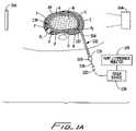
- FIG. 1illustrates the apparatus in accordance with the present invention inserted percutaneously into the annulus fibrosis of an intervertebral disc;
- FIG. 1Ais a view illustrating an alternate use of the apparatus of FIG. 1 ;
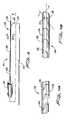
- FIG. 2is a schematic view of the apparatus in a disassembled condition illustrating an insertion cannula, a thermal or EMF probe and associated auxiliary electronic components;
- FIG. 3is a perspective view of the thermal probe of the apparatus
- FIGS. 4A and 4Bare enlarged views of the guidable region of the thermal or EMF probe illustrating the undulating cuts to facilitate bending movement of the guidable region in a predetermined direction;
- FIG. 5is a side cross-sectional view of the guidable region of the EMF probe
- FIG. 6is a cross-sectional view of the guidable region taken along the lines 6 - 6 of FIG. 3 ;
- FIG. 7is a perspective view illustrating the pre-bend configuration of the guidable region of the EMF probe
- FIG. 8is a side plan view of the proximal end of the EMF probe illustrating auxiliary electrical components associated with the probe;
- FIG. 9is a side cross-sectional view of the handle and associated electrical connections of the probe.
- FIG. 10is a cross-sectional view of the handle further illustrating of respective electrical components of the probe
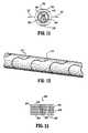
- FIG. 11is a cross-sectional view similar to the view of FIG. 6 and illustrating an alternate embodiment of the EMF probe
- FIG. 12is a perspective view of a guidable region of another alternate embodiment of the thermal or EMF probe.
- FIG. 13is a side view of the guidable region of another alternate embodiment of a thermal or EMF probe according to the present disclosure.
- the apparatus of the present disclosureprovides a more precise controlled positioning of a thermal probe in an intervertebral disc targeted for treatment. It will be readily apparent to a person skilled in the art that the apparatus and method of use of the apparatus can be used to treat/destroy body tissues in any body cavity or tissue locations that are accessible by percutaneous or endoscopic catheters or open surgical techniques, and is not limited to the disc area. Application of the device and method in all of these organs and tissues are intended to be included within the scope of this invention.
- proximalas is traditional, will refer to the end of the apparatus, or component thereof, which is closest to the operator, and the term “distal” will refer to the end of the apparatus, or component thereof, which is more remote from the operator.
- the intervertebral disc “D”is comprised of an annulus fibrosis “A” and a nucleus pulposus “N” disposed within the annulus fibrosis “A”.
- the annulus fibrosis “A”consists of a tough fibrous material which is arranged to define a plurality of annular cartilaginous rings “R” forming the natural striata of the annulus.
- the nucleus pulposus “N”consists primarily of an amorphous gel having a softer consistency than the annulus “A”.
- the nucleus pulposus “N”usually contains 70%-90% water by weight and mechanically functions similar to an incompressible hydrostatic material.
- the juncture or transition area of the annulus fibrosis “A” and nucleus pulposus “N”generally defines, for discussion purposes, an inner wall “W” of the annulus fibrosis “A”.
- the disc cortex “C”surrounds the annulus fibrosis “A”.
- the posterior, anterior and lateral aspects of the intervertebral discare identified as “P”, “AN” and “L”, respectively, with the opposed posterior-lateral aspects identified as “PL”.
- fissuresWhen mechanical stress is put upon a disc or when a disc degenerates with age, fissures, illustrated by the cracks “F” in the drawings, may occur in the posterior or posterior/lateral portions of the disc “D”. Problems with the nerves, fissures “F” and degenerative discs can give rise to various patient problems, such as back or leg pain originating from the irritation or occurrence of these abnormalities. Moreover, these conditions may ultimately result in conditions such as bulging or herniated discs.
- Applicantshave realized that heating and/or electromagnetic field (EMF) therapy of the intervertebral disc, preferably, the annulus “A” in the posterior “P” or posterior-lateral “PL” portions, will result in denervation of nerves and/or alterations and thermal ablation of disc structures, which will in turn produce alleviation of pain and healing of the disc.
- EMFelectromagnetic field
- FIG. 1it is desirable, as shown in FIG. 1 , to have a practical method of placing a thermal or electromagnetic probe in the posterior “P” and/or posterior-lateral “PL” portion of a disc “D” where these neural and aberrant structures occur for the relief of pain and other disc related problems.
- apparatus 100includes outer insertion or introducer cannula 102 , thermal or EMF probe 104 which is positionable within the cannula 102 and power source 106 which is connected to the thermal probe 102 .
- Introducer cannula 102preferably includes a rigid tubular shaft 108 defining a longitudinal axis “a” and having a rigid curved or arcuate portion 110 adjacent its distal end, angularly offset with respect to the longitudinal axis “a” at an angle ranging from about 15 to about 45.degree., preferably, about 23.degree.
- Shaft 108is preferably composed of a conductive material such as stainless steel or other suitable composition and is insulated with insulation along most of its length as indicated by the hatching in FIGS. 1 and 2 .
- shaft 108may be fabricated from a suitable polymeric material and formed by conventional injection molding techniques.
- the distal end portion 112 of shaft 108may be left uninsulated or exposed to permit electrical connection (e.g., for impedance measuring, etc.) to or contact with the tissue as cannula 102 is placed in the tissue.
- exposed portion 112may be connected to power source 106 to heat stimulate or micro-thermal generate the tissue to facilitate passage through the tissue.
- the extreme distal tip 114 of shaft 108is preferably sharpened to facilitate penetration into the disc tissue, i.e., through the bone of the cortex “C” and into the annulus “A”.
- a handle or housing 116is connected to the proximal end of cannula shaft 108 to facilitate manipulation of cannula 102 .
- Handle 116may include an index marker 118 to indicate the direction of arcuate portion 110 of cannula 102 such that when thermal or EMF probe 104 is introduced within cannula 102 , the surgeon may determine in which azimuthal rotational direction the curve is oriented.
- exemplary electrode shafts and insulation materialsare illustrated by the electrodes manufactured by Radionics, Inc., Burlington, Mass.
- Cannula shaft 108may have a diameter ranging from a fraction of a millimeter to several millimeters and a length of a few centimeters up to about 20 centimeters or more.
- cannula shaft 108may be fabricated from an MRI compatible material, including cobalt alloys, titanium, copper, nitinol, etc.
- Arcuate portion 110 of cannula 102may assume a variety of angular orientations depending on the surgical procedure to be performed. In one preferred embodiment for thermal or EMF therapy of the intervertebral disc, arcuate portion 110 is arranged such that thermal or EMF probe 104 is generally delivered from cannula 102 in orthogonal relation to longitudinal axis “a”.
- Power source or generator 106may be, for example, a radio frequency generator providing energy at frequencies between several kilohertz to several hundred megahertz.
- An example of a suitable generatoris the lesion generator, Model RFG-3C, available from Radionics, Inc., Burlington, Mass.
- Power source 106may have a power output ranging from several watts to several hundred watts, depending on clinical need.
- Power source 106may have control devices to increase or modulate power output as well as readout and display devices to monitor energy parameters such as voltage, current, power, frequency, temperature impedance 109 , etc., as appreciated by one skilled in the art.
- Other types of power sourcesare also contemplated, e.g., including resistive heating units, laser sources, or microwave generators.
- Thermal or EMF probe 104is positionable within cannula 102 and is adapted for reciprocal longitudinal movement therewithin.
- EMF probe 104is a monopolar system and is used in conjunction with an extended surface area grounding pad which contacts the patient's skin over a very large surface area relative the exposed surface area of the electrode tip.
- Thermal or EMF probe 104includes handle 120 and elongated member 122 extending distally from the handle 120 .
- Handle 120is advantageously dimensioned for gripping engagement by the user and may be fabricated from a suitable polymeric material or compatible metal.
- Handle 120houses the necessary electrical connectors for connecting to the external power source sensors, etc. Handle 120 may have a visual indicator, e.g., defining a flattened surface 121 , to indicate the direction of the elongated member 122 .
- Elongated member 122defines a longitudinal axis “e” as best illustrated in FIG. 4B , and has an exterior wall 124 defining axial bore or lumen 126 , ( FIG. 5 ), extending substantially along its length within the exterior wall.
- the exterior wall 124 at the proximal end of elongated member 122is solid or continuous.
- the distal end of the elongated memberincludes guidable region 128 .
- guidable region 128has a plurality of interrupted undulating grooves 130 defined in exterior wall 124 and spaced along the longitudinal axis “e” of the probe 104 .
- Grooves 130preferably define a generally sinusoidal or “s” configuration having a waveform arranged to oscillate about an axis “o” ( FIG. 4B ) extending in oblique relation to the axis “e” of the probe 104 .
- Grooves 130extend about the circumference of guidable region 128 and preferably extend radially inwardly to communicate with internal lumen 126 of probe 104 ( FIGS. 5 and 6 ), although, it is envisioned that grooves 130 may terminate within the exterior wall 124 of probe 104 without communicating with the internal lumen 126 .
- Grooves 130extend through a radial arc of approximately about 270.degree. to about 350.degree. with respect to the longitudinal axis “e”. Grooves 130 are interrupted by backbone 132 ( FIG. 4B ) which extends the length of guidable region 128 . In a preferred method of manufacture, each groove 130 is cut within the exterior wall 124 a predetermined distance to leave a solid portion between the ends of the cuts thereby forming the single backbone 132 .
- Backbone 132is dimensioned to resist radial arcing movement of guidable region 128 toward the backbone while permitting guidable region 128 to move in radial directions “A, B” ( FIGS. 6 and 7 ) across the backbone 132 .
- the undulating groove arrangement of guidable region 128permits the region 128 to bend or flex in opposed radial directions “A” and “B” along one radial plane to follow the ring like configuration of the natural striata of the annulus fibrosis “A” while also providing excellent torque transmission.
- the undulating groove arrangementalso provides a more streamline profile which, consequently, facilitates passage of the probe 104 through the annular tissue, as compared to conventional helical coil arrangements which are subject to “catching” tissue during passage. As depicted in FIG.
- guidable region 128may have a preset bend at an angle ranging from about 15.degree. to about 45.degree., preferably, about 30.degree. relative to the longitudinal axis “e” of the probe 104 .
- a preset bendfacilitates introduction of the probe 104 through the curved cannula into the annular tissue “A” to assist in initial guiding of the probe as it exits the cannula along the curved path between annulus tissue layers.
- flattened surface 121 of handle 120is aligned with the bend to indicate to the user the orientation of guidable region 128 .
- backbone 132also serves as a more direct electrical pathway from the energy source to the distal end portion of probe 104 and, therefore, advantageously reduces the electrical resistance of guidable region 128 thereby facilitating uniform lesion formation along the length of the exposed electrode tip.
- the distal tip 134 of guidable region 128is preferably blunt or rounded to prevent undesired entry or penetration of thermal probe into areas, including underlying nerves, the nucleus pulposus, etc., as will be discussed.
- the proximal end of thermal or EMF probe 104includes a plurality of etchings or markings 136 ( FIG. 2 ). Markings 136 indicate the degree of extension of guidable region 128 from cannula 102 .
- thermal or EMF probe 104When used as a radiofrequency probe, thermal or EMF probe 104 may be insulated except for guidable region 128 which may be left uninsulated for transmission of energy. Alternately, and in the preferred embodiment, thermal or EMF probe 104 may be uninsulated while cannula 102 functions as the insulating element of the apparatus. In this arrangement, the degree of extension of guidable region 128 beyond cannula 102 determines the heating capability of the probe 104 .
- thermal or EMF probe 104may further include a thermal sensor 138 , e.g., a thermocouple, thermistor, etc., extending through its internal lumen 126 .
- Sensor 138is preferably embedded in solder tip 139 which also closes the distal tip 134 of probe 104 .
- Thermal sensor 138provides temperature monitoring capability of the tissue being treated adjacent thermal or EMF probe 104 through temperature monitor 109 ( FIGS. 1 and 6 ).
- thermal or EMF probe 104further includes a guide wire 140 .
- Guide wire 140is disposed within internal lumen 128 of thermal or EMF probe 104 .
- Guide wire 140has sufficient rigidity to assist in advancing thermal or EMF probe 104 with annulus “A” while also permitting guidable region 128 of the probe 104 to flex and bend to conform to the path defined by the natural striata of the fibrous annulus tissue.
- Guide wire 140is also embedded in solder tip 139 at the distal end of probe 104 .
- thermosensor 138is wrapped about the distal end of guide wire 140 and embedded in the solder tip 139 .
- guide wire 140serves to carry electrical signals with elongated member 122 of probe 104 to the distal end of the probe 104 .
- guide wire 140 and elongated member 122are electrically connected to each other at their respective proximal ends through wire 143 (e.g. a #26 BUSS wire) which is soldered to the proximal end of the elongated member 122 .
- Wire 143 and guide wire 140are connected to an RF energy input pin 145 of handle 102 . (shown schematically in FIG. 8 ).
- This constructionprovides parallel dual pathways for the RF energy: 1) through elongated tubular member 122 of probe 104 originating from the proximal end thereof and traveling distally; and 2) through guide wire 140 to the distal end 134 of probe 104 .
- This dual path structure energy transmissionprovides a significant advantage in that it facilitates a more uniform application of RF energy along the entire length of the exposed distal end of EMF probe 104 .
- the remaining connectors of handle 102include pins 138 a , 138 b for connection to respective constantan and copper wires of the thermocouple 138 .
- only elongated member 122is connected to the RF energy input with the guide wire 140 being electrically isolated from the tube.
- thermal or EMF probe 104may further include flexible sleeve 142 which encloses thermal sensor 138 and guide wire 140 .
- Sleeve 142serves to maintain the alignment of thermal sensor 138 and guide wire 140 within thermal or EMF probe 104 and also prevents or minimizes entry of body fluids within the probe 104 .
- Sleeve 142preferably comprises a flexible polymer material, such as polyimide.
- Apparatus 100preferably includes an imaging system 144 to potentially monitor, control or verify the positioning of cannula 102 and/or thermal probe 104 .
- Imaging systems contemplatedinclude X-ray machines, fluoroscopic machines or an ultrasonic, CT, MRI, PET, or other imaging devices.
- element 146may be conjugate elements as illustrated by element 146 on the opposite portion of the patient's body to provide imaging data.
- the imaging machineis an X-ray machine
- element 146may be a detection device, such as an X-ray film, digital, X-ray detector, fluoroscopic device, etc.
- Use of imaging machines to monitor percutaneously placed electrodes into tissueis commonly practiced in the surgical field.
- apparatus 100may further include stylet 148 which is to be used in conjunction with cannula 102 .
- Stylet 148is positionable within the lumen of cannula 102 and preferably occludes the front opening of the cannula 102 to prevent entry of tissue, fluids, etc., during introduction of the cannula 102 within the intervertebral disc “D”.
- Stylet 148may include a proximally positioned hub 150 which mates with handle 116 of cannula 102 to lock the components together during insertion. Such locking mechanisms are appreciated by one skilled in the art.
- An impedance monitor 152can be connected, as shown by connection 154 , to stylet 148 and therefore communicates electrically with the exposed portion 112 of cannula 102 into which the stylet 148 is introduced to monitor impedance of the tissue adjacent the distal end of cannula 102 .
- connection of the impedance monitormay be made directly to the shaft of cannula 102 whereby impedance measurements are effectuated through the exposed distal end of the cannula 102 .
- impedance monitoringassists in determining the position of cannula tip 112 with respect to the patient's skin, the cortex “C” of the disc, the annulus “A”, and/or nucleus “NU” of the disc “ID”. These regions will have different impedance levels that are readily quantifiable. For example, for a fully insulated electrode or cannula with an exposed area of a few square millimeters at the cannula end, the impedance will change significantly from the position of the tip near to or contacting the cortex “C” of the disc to the region where the tip is within the annulus “A” of FIG.
- Stylet 148can be made of a rigid metal tubing with either a permanent bend 156 at its distal end to correspond to the curvature of arcuate portion 112 of cannula 102 or may be a straight guide wire to adapt to the curve of the cannula 102 when it is inserted within the cannula 102 .
- the hub 150 and connector 154can take various forms including luer hubs, plug-in-jack-type connections, integral cables, etc. By reference, example of electrodes and cables are illustrated in the product lines of Radionics, Inc., Burlington, Mass.
- the targeted intervertebral disc “D”is identified during a pre-operative phase of the surgery. Access to the intervertebral disc area is then ascertained, preferably, through percutaneous techniques or, less desirably, open surgical techniques. Cannula 102 with stylet 148 positioned and secured therein is introduced within the intervertebral disc “D” preferably from a posterior or posterior-lateral location as depicted in FIG. 1 . Alternatively, cannula 102 may be utilized without stylet 148 .
- the impedance of the tissue adjacent the distal end 114 of the cannula 102is monitored through the cannula 102 or alternatively via the impedance monitoring means associated with stylet 148 .
- Impedance monitoringmay be utilized to determine the position of cannula tip 114 with respect to the patient's skin, the cortex “C” of the disc, the annulus “A” and/or the nucleus “N” of the disc. As discussed above, these regions have different and quantifiable impedance levels thereby providing an indication to the user of the position of the cannula tip 112 in the tissue. Monitoring of the location of cannula 102 may also be confirmed with imaging system 144 .
- cannula tip 114 of cannula 102is positioned within the annulus fibrosis “A” of the intervertebral disc “D” at a posterior lateral “PL” location of the disc “D” without penetrating through inner wall “W” and into nucleus “N”.
- sharpened tip 114facilitates entry into the annulus “A”.
- cannula 102is angulated to position arcuate end portion 110 of the cannula 102 at the desired orientation within the annulus fibrosis “A”. Confirmation of the angular orientation of arcuate end portion 110 of cannula 102 is made through location of index marker 118 of the cannula 102 .
- arcuate end portion 110is arranged to deliver thermal probe 104 within the posterior section “P” of the intervertebral disc “D”.
- arcuate end portion 110is arranged to deliver thermal or EMF probe 104 toward the posterior-lateral “PL” and lateral “L” portion of the disc “D” as shown in phantom in FIG. 1 .
- Stylet 148is then removed from cannula 102 .
- Thermal or EMF probe 104is positioned within the internal lumen of cannula 102 and advanced through the cannula 102 .
- the pre-bent orientation of guidable region 128is arranged to coincide with the arcuate end portion of the cannula 102 . Confirmation of this orientation may be made with the location of the flattened surface 121 of the handle 102 .
- the probe 104is advanced to at least partially expose guidable region 128 of the thermal or EMF probe 104 from the distal end of cannula 102 .
- guidable region 128As thermal or EMF probe 104 enters the annulus fibrosis “A”, guidable region 128 , due to its strategic configuration and undulating groove 130 arrangement, flexes and conforms to the natural striata of the annular rings “R” of the annulus fibrosis, i.e., follows a path defined by the natural striata between two adjacent annular layers of tissue without entering the nucleus “N”. Once positioned, guidable region 128 occupies a substantial portion of the posterior “P” section of the annulus fibrosis “A” and preferably extends to the opposed posterior lateral section “PL” of the annulus fibrosis.
- the degree of extension of guidable region 128 beyond cannula 102may be indicated by distance or index markings 136 on the shaft of thermal or EMF probe 104 and confirmed through imaging system 144 .
- arcuate end portion 110is angulated to directly access the posterior lateral “PL” section of the annulus fibrosis “A” also without entering the nucleus pulposus.
- Thermal or EMF probe 104is thereafter advanced to position guidable region 128 within the lateral “L” and posterior/lateral “PL” sections of the annulus “A”.
- guidable region 128follows the arcuate path of the natural striata of the annulus “A” upon advancement therein.
- confirmation of the orientation of arcuate end portion 110is provided through index pin or marker adjacent handle of the cannula and can be also monitored through imaging system 144 .
- cannula 102may be positioned adjacent inner wall “W” of annulus.
- thermal or EMF probe 104is advanced within the annulus fibrosis “A” between adjacent layers, whereby guidable region 128 follows along the arcuate path defined by the adjacent annular tissue layers without penetrating through the wall “W” and into the nucleus “N”.
- the power source 106is activated whereby the thermal or EMF probe 104 delivers thermal energy and/or creates an electromagnetic field through guidable region 128 adjacent the intervertebral disc “D” to produce the thermal and/or EMF therapy in accordance with the present invention.
- Appropriate amounts of power, current or thermal heatmay be monitored from the external power source 106 and delivered for a certain amount of time as determined appropriate for clinical needs. For example, if denervation of nerves surrounding the disc is the objective, the tissue adjacent the probe end is heated to a temperature of from about 45.degree. to about 60.degree.
- the temperature in the tissueis raised to about 60-75.degree. C.
- the degree of extension of guidable region 128 from cannulacontrols the volume of disc tissue heated by the probe 104 .
- Thermal sensor 138 of thermal or EMF probe 104can provide information concerning the temperature of tissue adjacent the distal end.
- the impedance means associated with e.g., EMF probe 104can provide impedance measurements of the tissue thereby providing an indication of the degree of dessication, power rise, or charring, that may be taking place nea the thermal probe tip 134 . This indicates the effectiveness of the treatment and guards against unsafe contraindications of the therapy.
- the apparatus of the present inventionprovides significant advantages over the prior art.
- Cannula 102 and thermal or EMF probe 104permits the probe to be directed from a location across the posterior margin and into the lateral portion of the disc “D” by a direct pathway along, e.g., the natural striata of the annulus fibrosis or along the inner wall “W” of the annulus fibrosis.
- the present inventioneliminates the need of known devices to penetrate the inner annulus wall “W” and enter the nucleus “N” with a guide.
- a further advantage of the present inventionis that by monitoring impedance of cannula 102 and/or thermal or EMF probe 104 as it is being positioned within the disc, the surgeon can get additional information on the positioning of the cannula 102 as it is being put into the proper orientation.
- a further advantage of the present inventionis that by use of a curved introduction cannula a more efficacious direction of the probe can be achieved in the difficult lumbar or lumbar-sacral intervertebral discs.
- nearby heavy bony structuressuch as the iliac crest, can often obscure a placement of a curved probe parallel to the end plates or bony margins of adjacent intervertebral discs.
- the extension of a thermal probe parallel to the so-called end plates of the intervertebral discsis made possible with minimal repositioning and manipulation of the introduction cannula.
- the undulating groove arrangement and backbone of the guidable region of the thermal probepermits flexing in at least opposed radial directions along one radial plane to follow the arcuate path in the intervertebral disc.
- the undulating groove arrangementalso provides a streamline profile thereby facilitating entry and passage through the annulus tissue.
- power levels of fractions of a watt to several tens of wattsmay be used depending on the extent of heating required and the degree of therapy, denervation, and disc healing that is desired to be achieved.
- a further advantage of the present system and methodis that it enables simple, minimally-invasive, percutaneous, out-patient treatment of intradiscal pain without the need for open surgery as for example discectomies or spinal stabilization using plates, screws, and other instrumentation hardware.
- a further advantage of the present inventionis that it is simple to use and relatively economical. Compared to open surgery, the treatment of disc by percutaneous electrode placement represents only a few hours procedure and minimal hospitalization, with minimal morbidity to the patient. Open surgical procedures often require full anesthetic, extensive operating room time, and long hospital and home convalescence. Such open surgeries have considerable risk of morbidity and mortality and are much more expensive than a percutaneous procedure as described in accordance with the present invention.
- thermal or EMF probecould be, or incorporate, a resistive heating element(s) to heat the disc tissue by resistive heating.
- a resistive heating elementsuch as a nichrome wire or other type of resistive element, such that current delivered to the resistive element from the power generator will produce resistive heating within the element.
- resistive heating elementscan be devised by those skilled in the art.
- a resistive wirecan be fabricated to produce the guidable region.
- an internal resistive wirecan be placed inside the guidable region.
- the overall shaftmay be coated with an insulative material or other material to produce appropriate frictional, thermal, or electrical characteristics of the electrode when it is placed in the disc.
- an insulative material or other materialto produce appropriate frictional, thermal, or electrical characteristics of the electrode when it is placed in the disc.
- such a resistive elementmay have the appropriate flexibility, or steering capability so that it can be steered or directed favorably within the appropriate portion of the posterior and posterior-lateral portions of a disc, as illustrated by the discussion associated with FIG. 1 above.
- the distal endmay comprise a microwave antenna system or a laser fiber with transducer to distribute energy through thermal element into surrounding disc tissue.
- the thermal transmitting elementoperates as a microwave antenna or laser transmitting element, respectively.
- Other constructions to produce a heating elementcan be devised by those skilled in the art and are intended to be included within the scope of the present invention.
- the thermal or EMF probe provided with undulating cutscan be positioned such that the transmitting guidable region is disposed within the nucleus “N”.
- the probemust be configured and dimensioned so as to be more flexible than that of the previously disclosed embodiment.
- the probe 104may have a different diameter, thickness, material of fabrication and/or different arrangement and orientation of the grooves 130 . This is so because the probe which is to be inserted into and navigated within the nuclear material must have greater flexibility to prevent puncturing through the opposing side of the nucleus pulposus back into the annulus. Also, the greater flexibility facilitates navigation of the probe along the inner surface of the nucleus. Whereas, in the previously described embodiment, the opposite is desirable.
- the probe of the previously described embodimentmust be significantly more rigid to provide increased columnar strength to prevent kinking of the probe caused by greater relative resistance encountered by navigating in the annular tissue. The two embodiments would not, therefore, be interchangeable in their methods of use, i.e., operating in the annular tissue as for the previously described embodiment and operating in the nuclear material as for the embodiment of this paragraph.
- This probeis substantially similar to the probe of the prior embodiment but, includes, a second backbone 132 in diametrical opposed relation to the first backbone 132 .
- Second backbone 132is created by interrupting the sinusoidal grooves 130 adjacent the area of the second backbone 132 .
- This double backbone arrangementpermits radial movement along one plane in directions “A and “B”, but, also enhances rigidity of the guidable region, which may be desirable in certain surgical applications.
- FIG. 11there is illustrated a further alternative embodiment of the probe of the present invention.
- This probeis similar to the probe 104 of the first embodiment, but, includes a single continuous sinusoidal groove 170 extending the length of the guidable region 172 .
- This configurationprovides for uniform radial movement in all radial directions with respect to the longitudinal axis. Such configuration may be advantageous when inserting probe along a more serpenticious path.
- Groove 170extends to communicate with the internal lumen of the probe as discussed hereinabove.
- Thermal or EMF probe 104includes a guidable region 200 having a plurality of partial annular grooves 202 or cuts spaced along the longitudinal axis “Z”.
- FIG. 13is an enlarged plan view of a portion of guidable region 200 .
- annular grooves 202radially extend about the exterior wall through an arc which is slightly less than 360.degree., thereby providing a solid region 204 , 206 between the respective starting and ending positions of the groove.
- Adjacent grooves 202are radially displaced at about 180.degree.
- the overall effect of this arrangementis that guidable region can flex uniformly in all radial directions. This configuration is advantageous in insertion of the probe along a more serpenticious path.
Landscapes
- Health & Medical Sciences (AREA)
- Surgery (AREA)
- Life Sciences & Earth Sciences (AREA)
- Engineering & Computer Science (AREA)
- Heart & Thoracic Surgery (AREA)
- Medical Informatics (AREA)
- Otolaryngology (AREA)
- Plasma & Fusion (AREA)
- Physics & Mathematics (AREA)
- Biomedical Technology (AREA)
- Veterinary Medicine (AREA)
- Nuclear Medicine, Radiotherapy & Molecular Imaging (AREA)
- Molecular Biology (AREA)
- Animal Behavior & Ethology (AREA)
- General Health & Medical Sciences (AREA)
- Public Health (AREA)
- Cardiology (AREA)
- Surgical Instruments (AREA)
- Thermotherapy And Cooling Therapy Devices (AREA)
- Prostheses (AREA)
Abstract
Description
Claims (15)
Priority Applications (2)
| Application Number | Priority Date | Filing Date | Title |
|---|---|---|---|
| US11/266,569US7702397B2 (en) | 2000-09-07 | 2005-11-03 | Apparatus and method for treatment of an intervertebral disc |
| US12/754,046US20100274243A1 (en) | 2000-09-07 | 2010-04-05 | Apparatus and Method for Treatment of an Intervertebral Disc |
Applications Claiming Priority (4)
| Application Number | Priority Date | Filing Date | Title |
|---|---|---|---|
| US23075000P | 2000-09-07 | 2000-09-07 | |
| US09/948,409US6604003B2 (en) | 2000-09-07 | 2001-09-06 | Apparatus and method for treatment of an intervertebral disc |
| US10/439,881US6980862B2 (en) | 2000-09-07 | 2003-05-16 | Apparatus and method for treatment of an intervertebral disc |
| US11/266,569US7702397B2 (en) | 2000-09-07 | 2005-11-03 | Apparatus and method for treatment of an intervertebral disc |
Related Parent Applications (1)
| Application Number | Title | Priority Date | Filing Date |
|---|---|---|---|
| US10/439,881ContinuationUS6980862B2 (en) | 2000-09-07 | 2003-05-16 | Apparatus and method for treatment of an intervertebral disc |
Related Child Applications (1)
| Application Number | Title | Priority Date | Filing Date |
|---|---|---|---|
| US12/754,046ContinuationUS20100274243A1 (en) | 2000-09-07 | 2010-04-05 | Apparatus and Method for Treatment of an Intervertebral Disc |
Publications (2)
| Publication Number | Publication Date |
|---|---|
| US20060052848A1 US20060052848A1 (en) | 2006-03-09 |
| US7702397B2true US7702397B2 (en) | 2010-04-20 |
Family
ID=22866410
Family Applications (4)
| Application Number | Title | Priority Date | Filing Date |
|---|---|---|---|
| US09/948,409Expired - Fee RelatedUS6604003B2 (en) | 2000-09-07 | 2001-09-06 | Apparatus and method for treatment of an intervertebral disc |
| US10/439,881Expired - Fee RelatedUS6980862B2 (en) | 2000-09-07 | 2003-05-16 | Apparatus and method for treatment of an intervertebral disc |
| US11/266,569Expired - Fee RelatedUS7702397B2 (en) | 2000-09-07 | 2005-11-03 | Apparatus and method for treatment of an intervertebral disc |
| US12/754,046AbandonedUS20100274243A1 (en) | 2000-09-07 | 2010-04-05 | Apparatus and Method for Treatment of an Intervertebral Disc |
Family Applications Before (2)
| Application Number | Title | Priority Date | Filing Date |
|---|---|---|---|
| US09/948,409Expired - Fee RelatedUS6604003B2 (en) | 2000-09-07 | 2001-09-06 | Apparatus and method for treatment of an intervertebral disc |
| US10/439,881Expired - Fee RelatedUS6980862B2 (en) | 2000-09-07 | 2003-05-16 | Apparatus and method for treatment of an intervertebral disc |
Family Applications After (1)
| Application Number | Title | Priority Date | Filing Date |
|---|---|---|---|
| US12/754,046AbandonedUS20100274243A1 (en) | 2000-09-07 | 2010-04-05 | Apparatus and Method for Treatment of an Intervertebral Disc |
Country Status (8)
| Country | Link |
|---|---|
| US (4) | US6604003B2 (en) |
| EP (2) | EP1315463B1 (en) |
| JP (1) | JP4219679B2 (en) |
| AU (2) | AU2434501A (en) |
| CA (1) | CA2419991C (en) |
| DE (2) | DE60020171T2 (en) |
| ES (2) | ES2240225T3 (en) |
| WO (1) | WO2002019933A1 (en) |
Cited By (21)
| Publication number | Priority date | Publication date | Assignee | Title |
|---|---|---|---|---|
| US20100268207A1 (en)* | 2009-04-17 | 2010-10-21 | Kim Manwaring | Adjustable ferromagnetic coated conductor thermal surgical tool |
| US20110060324A1 (en)* | 2008-12-31 | 2011-03-10 | Ardian, Inc. | Apparatus, systems, and methods for achieving intravascular, thermally-induced renal neuromodulation |
| US8617151B2 (en) | 2009-04-17 | 2013-12-31 | Domain Surgical, Inc. | System and method of controlling power delivery to a surgical instrument |
| US8728075B2 (en) | 2010-04-26 | 2014-05-20 | Medtronic Ardian Luxembourg S.A.R.L. | Multi-directional deflectable catheter apparatuses, systems, and methods for renal neuromodulation |
| US8774913B2 (en) | 2002-04-08 | 2014-07-08 | Medtronic Ardian Luxembourg S.A.R.L. | Methods and apparatus for intravasculary-induced neuromodulation |
| US8858544B2 (en) | 2011-05-16 | 2014-10-14 | Domain Surgical, Inc. | Surgical instrument guide |
| US8915909B2 (en) | 2011-04-08 | 2014-12-23 | Domain Surgical, Inc. | Impedance matching circuit |
| US8932279B2 (en) | 2011-04-08 | 2015-01-13 | Domain Surgical, Inc. | System and method for cooling of a heated surgical instrument and/or surgical site and treating tissue |
| US9044575B2 (en) | 2012-10-22 | 2015-06-02 | Medtronic Adrian Luxembourg S.a.r.l. | Catheters with enhanced flexibility and associated devices, systems, and methods |
| US9078655B2 (en) | 2009-04-17 | 2015-07-14 | Domain Surgical, Inc. | Heated balloon catheter |
| US9107666B2 (en) | 2009-04-17 | 2015-08-18 | Domain Surgical, Inc. | Thermal resecting loop |
| US9125661B2 (en) | 2002-04-08 | 2015-09-08 | Medtronic Ardian Luxembourg S.A.R.L. | Methods and apparatus for renal neuromodulation |
| US9131978B2 (en) | 2002-04-08 | 2015-09-15 | Medtronic Ardian Luxembourg S.A.R.L. | Methods for bilateral renal neuromodulation |
| US9131977B2 (en) | 2009-04-17 | 2015-09-15 | Domain Surgical, Inc. | Layered ferromagnetic coated conductor thermal surgical tool |
| US9265556B2 (en) | 2009-04-17 | 2016-02-23 | Domain Surgical, Inc. | Thermally adjustable surgical tool, balloon catheters and sculpting of biologic materials |
| US9399115B2 (en) | 2012-10-22 | 2016-07-26 | Medtronic Ardian Luxembourg S.A.R.L. | Catheters with enhanced flexibility and associated devices, systems, and methods |
| US9526558B2 (en) | 2011-09-13 | 2016-12-27 | Domain Surgical, Inc. | Sealing and/or cutting instrument |
| US10111697B2 (en) | 2003-09-26 | 2018-10-30 | DePuy Synthes Products, Inc. | Device for delivering viscous material |
| US10357306B2 (en) | 2014-05-14 | 2019-07-23 | Domain Surgical, Inc. | Planar ferromagnetic coated surgical tip and method for making |
| US10433905B2 (en) | 2013-03-15 | 2019-10-08 | Medtronic Ardian Luxembourg S.A.R.L. | Multi-electrode apposition judgment using pressure elements |
| US10548663B2 (en) | 2013-05-18 | 2020-02-04 | Medtronic Ardian Luxembourg S.A.R.L. | Neuromodulation catheters with shafts for enhanced flexibility and control and associated devices, systems, and methods |
Families Citing this family (233)
| Publication number | Priority date | Publication date | Assignee | Title |
|---|---|---|---|---|
| US6602248B1 (en) | 1995-06-07 | 2003-08-05 | Arthro Care Corp. | Methods for repairing damaged intervertebral discs |
| US20050004634A1 (en) | 1995-06-07 | 2005-01-06 | Arthrocare Corporation | Methods for electrosurgical treatment of spinal tissue |
| WO2003024506A2 (en) | 2001-09-14 | 2003-03-27 | Arthrocare Corporation | Methods and apparatus for treating intervertebral discs |
| US7393351B2 (en) | 1995-06-07 | 2008-07-01 | Arthrocare Corporation | Apparatus and methods for treating cervical inter-vertebral discs |
| US6095149A (en)* | 1996-08-13 | 2000-08-01 | Oratec Interventions, Inc. | Method for treating intervertebral disc degeneration |
| US6726684B1 (en) | 1996-07-16 | 2004-04-27 | Arthrocare Corporation | Methods for electrosurgical spine surgery |
| US6620155B2 (en) | 1996-07-16 | 2003-09-16 | Arthrocare Corp. | System and methods for electrosurgical tissue contraction within the spine |
| US7357798B2 (en) | 1996-07-16 | 2008-04-15 | Arthrocare Corporation | Systems and methods for electrosurgical prevention of disc herniations |
| US7069087B2 (en) | 2000-02-25 | 2006-06-27 | Oratec Interventions, Inc. | Apparatus and method for accessing and performing a function within an intervertebral disc |
| US6733496B2 (en)* | 2001-06-06 | 2004-05-11 | Oratec Interventions, Inc. | Intervertebral disc device employing flexible probe |
| US6726685B2 (en)* | 2001-06-06 | 2004-04-27 | Oratec Interventions, Inc. | Intervertebral disc device employing looped probe |
| US6126682A (en) | 1996-08-13 | 2000-10-03 | Oratec Interventions, Inc. | Method for treating annular fissures in intervertebral discs |
| US6832997B2 (en) | 2001-06-06 | 2004-12-21 | Oratec Interventions, Inc. | Electromagnetic energy delivery intervertebral disc treatment devices |
| EP1063931A2 (en) | 1998-03-19 | 2001-01-03 | Oratec Interventions, Inc. | Catheter for delivery of energy to a surgical site |
| US7449019B2 (en) | 1999-01-25 | 2008-11-11 | Smith & Nephew, Inc. | Intervertebral decompression |
| US7935147B2 (en) | 1999-10-20 | 2011-05-03 | Anulex Technologies, Inc. | Method and apparatus for enhanced delivery of treatment device to the intervertebral disc annulus |
| US8128698B2 (en) | 1999-10-20 | 2012-03-06 | Anulex Technologies, Inc. | Method and apparatus for the treatment of the intervertebral disc annulus |
| US6592625B2 (en) | 1999-10-20 | 2003-07-15 | Anulex Technologies, Inc. | Spinal disc annulus reconstruction method and spinal disc annulus stent |
| US8632590B2 (en) | 1999-10-20 | 2014-01-21 | Anulex Technologies, Inc. | Apparatus and methods for the treatment of the intervertebral disc |
| US7615076B2 (en) | 1999-10-20 | 2009-11-10 | Anulex Technologies, Inc. | Method and apparatus for the treatment of the intervertebral disc annulus |
| US7004970B2 (en) | 1999-10-20 | 2006-02-28 | Anulex Technologies, Inc. | Methods and devices for spinal disc annulus reconstruction and repair |
| US7951201B2 (en) | 1999-10-20 | 2011-05-31 | Anulex Technologies, Inc. | Method and apparatus for the treatment of the intervertebral disc annulus |
| US7052516B2 (en) | 1999-10-20 | 2006-05-30 | Anulex Technologies, Inc. | Spinal disc annulus reconstruction method and deformable spinal disc annulus stent |
| US7811282B2 (en) | 2000-03-06 | 2010-10-12 | Salient Surgical Technologies, Inc. | Fluid-assisted electrosurgical devices, electrosurgical unit with pump and methods of use thereof |
| ES2306706T3 (en)* | 2000-03-06 | 2008-11-16 | Salient Surgical Technologies, Inc. | FLUID SUPPLY SYSTEM AND CONTROLLER FOR ELECTROCHURGICAL DEVICES. |
| US8048070B2 (en) | 2000-03-06 | 2011-11-01 | Salient Surgical Technologies, Inc. | Fluid-assisted medical devices, systems and methods |
| US6953461B2 (en) | 2002-05-16 | 2005-10-11 | Tissuelink Medical, Inc. | Fluid-assisted medical devices, systems and methods |
| US6689131B2 (en) | 2001-03-08 | 2004-02-10 | Tissuelink Medical, Inc. | Electrosurgical device having a tissue reduction sensor |
| US6558385B1 (en)* | 2000-09-22 | 2003-05-06 | Tissuelink Medical, Inc. | Fluid-assisted medical device |
| US6805695B2 (en) | 2000-04-04 | 2004-10-19 | Spinalabs, Llc | Devices and methods for annular repair of intervertebral discs |
| US6402750B1 (en)* | 2000-04-04 | 2002-06-11 | Spinlabs, Llc | Devices and methods for the treatment of spinal disorders |
| US20030158545A1 (en)* | 2000-09-28 | 2003-08-21 | Arthrocare Corporation | Methods and apparatus for treating back pain |
| US6638276B2 (en) | 2001-06-06 | 2003-10-28 | Oratec Interventions, Inc. | Intervertebral disc device employing prebent sheath |
| US6994706B2 (en)* | 2001-08-13 | 2006-02-07 | Minnesota Medical Physics, Llc | Apparatus and method for treatment of benign prostatic hyperplasia |
| US20030069569A1 (en)* | 2001-08-29 | 2003-04-10 | Burdette Everette C. | Ultrasound device for treatment of intervertebral disc tissue |
| AU2002357166A1 (en)* | 2001-12-12 | 2003-06-23 | Tissuelink Medical, Inc. | Fluid-assisted medical devices, systems and methods |
| EP1465701A4 (en)* | 2002-01-15 | 2008-08-13 | Univ California | SYSTEM AND METHOD FOR DIRECTIONAL ULTRASONIC THERAPY OF SKELETAL JOINTS |
| US6757565B2 (en) | 2002-02-08 | 2004-06-29 | Oratec Interventions, Inc. | Electrosurgical instrument having a predetermined heat profile |
| US8518036B2 (en) | 2002-03-05 | 2013-08-27 | Kimberly-Clark Inc. | Electrosurgical tissue treatment method |
| US8043287B2 (en) | 2002-03-05 | 2011-10-25 | Kimberly-Clark Inc. | Method of treating biological tissue |
| US8882755B2 (en)* | 2002-03-05 | 2014-11-11 | Kimberly-Clark Inc. | Electrosurgical device for treatment of tissue |
| US6896675B2 (en) | 2002-03-05 | 2005-05-24 | Baylis Medical Company Inc. | Intradiscal lesioning device |
| US8175711B2 (en) | 2002-04-08 | 2012-05-08 | Ardian, Inc. | Methods for treating a condition or disease associated with cardio-renal function |
| US6978174B2 (en) | 2002-04-08 | 2005-12-20 | Ardian, Inc. | Methods and devices for renal nerve blocking |
| US9636174B2 (en) | 2002-04-08 | 2017-05-02 | Medtronic Ardian Luxembourg S.A.R.L. | Methods for therapeutic renal neuromodulation |
| US7617005B2 (en) | 2002-04-08 | 2009-11-10 | Ardian, Inc. | Methods and apparatus for thermally-induced renal neuromodulation |
| US7853333B2 (en) | 2002-04-08 | 2010-12-14 | Ardian, Inc. | Methods and apparatus for multi-vessel renal neuromodulation |
| US20070135875A1 (en) | 2002-04-08 | 2007-06-14 | Ardian, Inc. | Methods and apparatus for thermally-induced renal neuromodulation |
| US8145317B2 (en)* | 2002-04-08 | 2012-03-27 | Ardian, Inc. | Methods for renal neuromodulation |
| US7756583B2 (en) | 2002-04-08 | 2010-07-13 | Ardian, Inc. | Methods and apparatus for intravascularly-induced neuromodulation |
| US20070129761A1 (en) | 2002-04-08 | 2007-06-07 | Ardian, Inc. | Methods for treating heart arrhythmia |
| US7620451B2 (en) | 2005-12-29 | 2009-11-17 | Ardian, Inc. | Methods and apparatus for pulsed electric field neuromodulation via an intra-to-extravascular approach |
| US9308044B2 (en) | 2002-04-08 | 2016-04-12 | Medtronic Ardian Luxembourg S.A.R.L. | Methods for therapeutic renal neuromodulation |
| US20140018880A1 (en) | 2002-04-08 | 2014-01-16 | Medtronic Ardian Luxembourg S.A.R.L. | Methods for monopolar renal neuromodulation |
| US7162303B2 (en) | 2002-04-08 | 2007-01-09 | Ardian, Inc. | Renal nerve stimulation method and apparatus for treatment of patients |
| US9308043B2 (en) | 2002-04-08 | 2016-04-12 | Medtronic Ardian Luxembourg S.A.R.L. | Methods for monopolar renal neuromodulation |
| US20080213331A1 (en) | 2002-04-08 | 2008-09-04 | Ardian, Inc. | Methods and devices for renal nerve blocking |
| US8774922B2 (en) | 2002-04-08 | 2014-07-08 | Medtronic Ardian Luxembourg S.A.R.L. | Catheter apparatuses having expandable balloons for renal neuromodulation and associated systems and methods |
| US8131371B2 (en)* | 2002-04-08 | 2012-03-06 | Ardian, Inc. | Methods and apparatus for monopolar renal neuromodulation |
| US8145316B2 (en) | 2002-04-08 | 2012-03-27 | Ardian, Inc. | Methods and apparatus for renal neuromodulation |
| US8347891B2 (en) | 2002-04-08 | 2013-01-08 | Medtronic Ardian Luxembourg S.A.R.L. | Methods and apparatus for performing a non-continuous circumferential treatment of a body lumen |
| US20040082859A1 (en) | 2002-07-01 | 2004-04-29 | Alan Schaer | Method and apparatus employing ultrasound energy to treat body sphincters |
| EP1542587B1 (en) | 2002-08-24 | 2011-04-27 | St. Jude Medical, Atrial Fibrillation Division, Inc. | Method and apparatus for locating the fossa ovalis and performing transseptal puncture |
| US7744651B2 (en) | 2002-09-18 | 2010-06-29 | Warsaw Orthopedic, Inc | Compositions and methods for treating intervertebral discs with collagen-based materials |
| US20040054414A1 (en) | 2002-09-18 | 2004-03-18 | Trieu Hai H. | Collagen-based materials and methods for augmenting intervertebral discs |
| US6827716B2 (en)* | 2002-09-30 | 2004-12-07 | Depuy Spine, Inc. | Method of identifying and treating a pathologic region of an intervertebral disc |
| US6907884B2 (en) | 2002-09-30 | 2005-06-21 | Depay Acromed, Inc. | Method of straddling an intraosseous nerve |
| US8361067B2 (en) | 2002-09-30 | 2013-01-29 | Relievant Medsystems, Inc. | Methods of therapeutically heating a vertebral body to treat back pain |
| WO2004039416A2 (en) | 2002-10-29 | 2004-05-13 | Tissuelink Medical, Inc. | Fluid-assisted electrosurgical scissors and methods |
| JP2006515765A (en) | 2002-11-15 | 2006-06-08 | エスディージーアイ・ホールディングス・インコーポレーテッド | Collagen-based materials and methods for treating synovial joints |
| US6926713B2 (en)* | 2002-12-11 | 2005-08-09 | Boston Scientific Scimed, Inc. | Angle indexer for medical devices |
| ES2545328T3 (en) | 2003-03-14 | 2015-09-10 | Depuy Spine, Inc. | Bone cement hydraulic injection device in percutaneous vertebroplasty |
| US8066713B2 (en) | 2003-03-31 | 2011-11-29 | Depuy Spine, Inc. | Remotely-activated vertebroplasty injection device |
| US7794456B2 (en) | 2003-05-13 | 2010-09-14 | Arthrocare Corporation | Systems and methods for electrosurgical intervertebral disc replacement |
| US8415407B2 (en)* | 2004-03-21 | 2013-04-09 | Depuy Spine, Inc. | Methods, materials, and apparatus for treating bone and other tissue |
| US7708733B2 (en) | 2003-10-20 | 2010-05-04 | Arthrocare Corporation | Electrosurgical method and apparatus for removing tissue within a bone body |
| US7727232B1 (en) | 2004-02-04 | 2010-06-01 | Salient Surgical Technologies, Inc. | Fluid-assisted medical devices and methods |
| WO2005102433A2 (en)* | 2004-04-23 | 2005-11-03 | Leonard Edward Forrest | Device for treatment or evacuation of intervertebral disc |
| US8292931B2 (en)* | 2004-04-23 | 2012-10-23 | Leonard Edward Forrest | Method and device for placing materials in the spine |
| US8257311B2 (en)* | 2004-04-23 | 2012-09-04 | Leonard Edward Forrest | Method and device for treatment of the spine |
| US7389148B1 (en)* | 2004-05-05 | 2008-06-17 | Pacesetter, Inc. | Electrode design for defibrillation and/or sensing capabilities |
| US20050273093A1 (en)* | 2004-06-04 | 2005-12-08 | Scimed Life Systems, Inc. | Method of treating herniated intervertebral discs using cooled ablation |
| CN101065080B (en) | 2004-07-30 | 2021-10-29 | 德普伊新特斯产品有限责任公司 | Materials and Instruments for Manipulating Bone and Other Tissues |
| US20060224219A1 (en)* | 2005-03-31 | 2006-10-05 | Sherwood Services Ag | Method of using neural stimulation during nucleoplasty procedures |
| US20100145424A1 (en)* | 2004-09-21 | 2010-06-10 | Covidien Ag | Method for Treatment of an Intervertebral Disc |
| US20060064145A1 (en)* | 2004-09-21 | 2006-03-23 | Podhajsky Ronald J | Method for treatment of an intervertebral disc |
| ES2357084T3 (en) | 2004-10-06 | 2011-04-18 | Covidien Ag | SYSTEMS AND METHOD TO THERMALLY PROFILE RADIO FREQUENCY ELECTRODES. |
| US20080015664A1 (en) | 2004-10-06 | 2008-01-17 | Podhajsky Ronald J | Systems and methods for thermally profiling radiofrequency electrodes |
| US8430881B2 (en) | 2004-10-15 | 2013-04-30 | Baxano, Inc. | Mechanical tissue modification devices and methods |
| US8062300B2 (en) | 2006-05-04 | 2011-11-22 | Baxano, Inc. | Tissue removal with at least partially flexible devices |
| US8257356B2 (en) | 2004-10-15 | 2012-09-04 | Baxano, Inc. | Guidewire exchange systems to treat spinal stenosis |
| US9101386B2 (en) | 2004-10-15 | 2015-08-11 | Amendia, Inc. | Devices and methods for treating tissue |
| US7857813B2 (en) | 2006-08-29 | 2010-12-28 | Baxano, Inc. | Tissue access guidewire system and method |
| US8221397B2 (en) | 2004-10-15 | 2012-07-17 | Baxano, Inc. | Devices and methods for tissue modification |
| US9247952B2 (en) | 2004-10-15 | 2016-02-02 | Amendia, Inc. | Devices and methods for tissue access |
| US8048080B2 (en) | 2004-10-15 | 2011-11-01 | Baxano, Inc. | Flexible tissue rasp |
| US20100331883A1 (en) | 2004-10-15 | 2010-12-30 | Schmitz Gregory P | Access and tissue modification systems and methods |
| US7963915B2 (en) | 2004-10-15 | 2011-06-21 | Baxano, Inc. | Devices and methods for tissue access |
| US20110190772A1 (en) | 2004-10-15 | 2011-08-04 | Vahid Saadat | Powered tissue modification devices and methods |
| US7578819B2 (en) | 2005-05-16 | 2009-08-25 | Baxano, Inc. | Spinal access and neural localization |
| US7738969B2 (en) | 2004-10-15 | 2010-06-15 | Baxano, Inc. | Devices and methods for selective surgical removal of tissue |
| US7887538B2 (en) | 2005-10-15 | 2011-02-15 | Baxano, Inc. | Methods and apparatus for tissue modification |
| JP5243034B2 (en) | 2004-10-15 | 2013-07-24 | バクサノ,インク. | Tissue removal device |
| US7959577B2 (en) | 2007-09-06 | 2011-06-14 | Baxano, Inc. | Method, system, and apparatus for neural localization |
| US7938830B2 (en) | 2004-10-15 | 2011-05-10 | Baxano, Inc. | Powered tissue modification devices and methods |
| US8613745B2 (en) | 2004-10-15 | 2013-12-24 | Baxano Surgical, Inc. | Methods, systems and devices for carpal tunnel release |
| DE102004055866B4 (en)* | 2004-11-19 | 2009-04-09 | Söring GmbH | Device for destruction of tumor tissue |
| WO2006058221A2 (en) | 2004-11-24 | 2006-06-01 | Abdou Samy M | Devices and methods for inter-vertebral orthopedic device placement |
| US7627380B2 (en)* | 2005-03-31 | 2009-12-01 | Covidien Ag | Method and apparatus for monitoring disc pressure during heat treatment of an intervertebral disc |
| US7828832B2 (en)* | 2005-04-18 | 2010-11-09 | Medtronic Vascular, Inc. | Intravascular deployment device with improved deployment capability |
| EP1874210B1 (en)* | 2005-04-29 | 2010-02-24 | Stryker Corporation | Medical bipolar electrode assembly with cannula and removable supply electrode |
| US7749232B2 (en)* | 2005-05-24 | 2010-07-06 | Anthony Salerni | Electromagnetically guided spinal rod system and related methods |
| US9381024B2 (en) | 2005-07-31 | 2016-07-05 | DePuy Synthes Products, Inc. | Marked tools |
| US9918767B2 (en) | 2005-08-01 | 2018-03-20 | DePuy Synthes Products, Inc. | Temperature control system |
| US20070055259A1 (en)* | 2005-08-17 | 2007-03-08 | Norton Britt K | Apparatus and methods for removal of intervertebral disc tissues |
| US20070073397A1 (en)* | 2005-09-15 | 2007-03-29 | Mckinley Laurence M | Disc nucleus prosthesis and its method of insertion and revision |
| US8062298B2 (en) | 2005-10-15 | 2011-11-22 | Baxano, Inc. | Flexible tissue removal devices and methods |
| US8366712B2 (en) | 2005-10-15 | 2013-02-05 | Baxano, Inc. | Multiple pathways for spinal nerve root decompression from a single access point |
| US8092456B2 (en) | 2005-10-15 | 2012-01-10 | Baxano, Inc. | Multiple pathways for spinal nerve root decompression from a single access point |
| US8360629B2 (en) | 2005-11-22 | 2013-01-29 | Depuy Spine, Inc. | Mixing apparatus having central and planetary mixing elements |
| US20070162062A1 (en)* | 2005-12-08 | 2007-07-12 | Norton Britt K | Reciprocating apparatus and methods for removal of intervertebral disc tissues |
| US8273005B2 (en)* | 2006-02-02 | 2012-09-25 | Samy Abdou | Treatment of pain, neurological dysfunction and neoplasms using radiation delivery catheters |
| US7879034B2 (en) | 2006-03-02 | 2011-02-01 | Arthrocare Corporation | Internally located return electrode electrosurgical apparatus, system and method |
| US8075556B2 (en)* | 2006-05-23 | 2011-12-13 | Andres Betts | High frequency epidural neuromodulation catheter for effectuating RF treatment in spinal canal and method of using same |
| US20070287991A1 (en)* | 2006-06-08 | 2007-12-13 | Mckay William F | Devices and methods for detection of markers of axial pain with or without radiculopathy |
| US20070299403A1 (en)* | 2006-06-23 | 2007-12-27 | Crowe John E | Directional introducer |
| US8399619B2 (en) | 2006-06-30 | 2013-03-19 | Warsaw Orthopedic, Inc. | Injectable collagen material |
| US8118779B2 (en) | 2006-06-30 | 2012-02-21 | Warsaw Orthopedic, Inc. | Collagen delivery device |
| AU2007297097A1 (en) | 2006-09-14 | 2008-03-20 | Depuy Spine, Inc. | Bone cement and methods of use thereof |
| US8950929B2 (en) | 2006-10-19 | 2015-02-10 | DePuy Synthes Products, LLC | Fluid delivery system |
| US8840621B2 (en) | 2006-11-03 | 2014-09-23 | Innovative Spine, Inc. | Spinal access systems and methods |
| US8057481B2 (en) | 2006-11-03 | 2011-11-15 | Innovative Spine, Llc | System and method for providing surgical access to a spine |
| US20080125747A1 (en)* | 2006-11-28 | 2008-05-29 | Smith & Nephew, Inc.-Tn | Passive thermal spine catheter |
| EP2174118A4 (en)* | 2007-02-01 | 2015-06-24 | Ls Biopath Inc | Optical system for identification and characterization of abnormal tissue and cells |
| US8187267B2 (en)* | 2007-05-23 | 2012-05-29 | St. Jude Medical, Atrial Fibrillation Division, Inc. | Ablation catheter with flexible tip and methods of making the same |
| US8517999B2 (en) | 2007-04-04 | 2013-08-27 | St. Jude Medical, Atrial Fibrillation Division, Inc. | Irrigated catheter with improved fluid flow |
| US8979837B2 (en)* | 2007-04-04 | 2015-03-17 | St. Jude Medical, Atrial Fibrillation Division, Inc. | Flexible tip catheter with extended fluid lumen |
| US8764742B2 (en) | 2007-04-04 | 2014-07-01 | St. Jude Medical, Atrial Fibrillation Division, Inc. | Irrigated catheter |
| US10183183B2 (en) | 2007-04-13 | 2019-01-22 | Acoustic Medsystems, Inc. | Acoustic applicators for controlled thermal modification of tissue |
| US8734440B2 (en)* | 2007-07-03 | 2014-05-27 | St. Jude Medical, Atrial Fibrillation Division, Inc. | Magnetically guided catheter |
| US10220187B2 (en) | 2010-06-16 | 2019-03-05 | St. Jude Medical, Llc | Ablation catheter having flexible tip with multiple flexible electrode segments |
| US11395694B2 (en)* | 2009-05-07 | 2022-07-26 | St. Jude Medical, Llc | Irrigated ablation catheter with multiple segmented ablation electrodes |
| US8974454B2 (en) | 2009-12-31 | 2015-03-10 | St. Jude Medical, Atrial Fibrillation Division, Inc. | Kit for non-invasive electrophysiology procedures and method of its use |
| EP2173426B1 (en) | 2007-07-03 | 2016-04-20 | Irvine Biomedical, Inc. | Magnetically guided catheter |
| US8192436B2 (en) | 2007-12-07 | 2012-06-05 | Baxano, Inc. | Tissue modification devices |
| US8992517B2 (en) | 2008-04-29 | 2015-03-31 | Virginia Tech Intellectual Properties Inc. | Irreversible electroporation to treat aberrant cell masses |
| US11272979B2 (en) | 2008-04-29 | 2022-03-15 | Virginia Tech Intellectual Properties, Inc. | System and method for estimating tissue heating of a target ablation zone for electrical-energy based therapies |
| US9598691B2 (en) | 2008-04-29 | 2017-03-21 | Virginia Tech Intellectual Properties, Inc. | Irreversible electroporation to create tissue scaffolds |
| US11254926B2 (en) | 2008-04-29 | 2022-02-22 | Virginia Tech Intellectual Properties, Inc. | Devices and methods for high frequency electroporation |
| US10272178B2 (en) | 2008-04-29 | 2019-04-30 | Virginia Tech Intellectual Properties Inc. | Methods for blood-brain barrier disruption using electrical energy |
| US10702326B2 (en) | 2011-07-15 | 2020-07-07 | Virginia Tech Intellectual Properties, Inc. | Device and method for electroporation based treatment of stenosis of a tubular body part |
| US9867652B2 (en) | 2008-04-29 | 2018-01-16 | Virginia Tech Intellectual Properties, Inc. | Irreversible electroporation using tissue vasculature to treat aberrant cell masses or create tissue scaffolds |
| US9283051B2 (en) | 2008-04-29 | 2016-03-15 | Virginia Tech Intellectual Properties, Inc. | System and method for estimating a treatment volume for administering electrical-energy based therapies |
| US9198733B2 (en) | 2008-04-29 | 2015-12-01 | Virginia Tech Intellectual Properties, Inc. | Treatment planning for electroporation-based therapies |
| US10117707B2 (en) | 2008-04-29 | 2018-11-06 | Virginia Tech Intellectual Properties, Inc. | System and method for estimating tissue heating of a target ablation zone for electrical-energy based therapies |
| US10238447B2 (en) | 2008-04-29 | 2019-03-26 | Virginia Tech Intellectual Properties, Inc. | System and method for ablating a tissue site by electroporation with real-time monitoring of treatment progress |
| US10245098B2 (en) | 2008-04-29 | 2019-04-02 | Virginia Tech Intellectual Properties, Inc. | Acute blood-brain barrier disruption using electrical energy based therapy |
| US8409206B2 (en) | 2008-07-01 | 2013-04-02 | Baxano, Inc. | Tissue modification devices and methods |
| US9314253B2 (en) | 2008-07-01 | 2016-04-19 | Amendia, Inc. | Tissue modification devices and methods |
| US8398641B2 (en) | 2008-07-01 | 2013-03-19 | Baxano, Inc. | Tissue modification devices and methods |
| AU2009271047B2 (en) | 2008-07-14 | 2014-04-17 | Baxano Surgical, Inc. | Tissue modification devices |
| US20100076422A1 (en)* | 2008-09-24 | 2010-03-25 | Tyco Healthcare Group Lp | Thermal Treatment of Nucleus Pulposus |
| US10028753B2 (en) | 2008-09-26 | 2018-07-24 | Relievant Medsystems, Inc. | Spine treatment kits |
| CA2737374C (en) | 2008-09-26 | 2017-03-28 | Relievant Medsystems, Inc. | Systems and methods for navigating an instrument through bone |
| US8163022B2 (en) | 2008-10-14 | 2012-04-24 | Anulex Technologies, Inc. | Method and apparatus for the treatment of the intervertebral disc annulus |
| US20100168739A1 (en)* | 2008-12-31 | 2010-07-01 | Ardian, Inc. | Apparatus, systems, and methods for achieving intravascular, thermally-induced renal neuromodulation |
| WO2010080886A1 (en) | 2009-01-09 | 2010-07-15 | Recor Medical, Inc. | Methods and apparatus for treatment of mitral valve in insufficiency |
| EP2405823A4 (en) | 2009-03-13 | 2012-07-04 | Baxano Inc | Flexible neural localization devices and methods |
| US8632534B2 (en) | 2009-04-03 | 2014-01-21 | Angiodynamics, Inc. | Irreversible electroporation (IRE) for congestive obstructive pulmonary disease (COPD) |
| US11638603B2 (en) | 2009-04-09 | 2023-05-02 | Virginia Tech Intellectual Properties, Inc. | Selective modulation of intracellular effects of cells using pulsed electric fields |
| US11382681B2 (en) | 2009-04-09 | 2022-07-12 | Virginia Tech Intellectual Properties, Inc. | Device and methods for delivery of high frequency electrical pulses for non-thermal ablation |
| WO2010138919A2 (en) | 2009-05-28 | 2010-12-02 | Angiodynamics, Inc. | System and method for synchronizing energy delivery to the cardiac rhythm |
| JP2012529335A (en)* | 2009-06-09 | 2012-11-22 | ユー アンド アイ コーポレーション | Directionally adjustable electrode body and guide tube for selective removal of body tissue |
| US9895189B2 (en) | 2009-06-19 | 2018-02-20 | Angiodynamics, Inc. | Methods of sterilization and treating infection using irreversible electroporation |
| US8394102B2 (en) | 2009-06-25 | 2013-03-12 | Baxano, Inc. | Surgical tools for treatment of spinal stenosis |
| US9113950B2 (en) | 2009-11-04 | 2015-08-25 | Regenerative Sciences, Llc | Therapeutic delivery device |
| US8764806B2 (en) | 2009-12-07 | 2014-07-01 | Samy Abdou | Devices and methods for minimally invasive spinal stabilization and instrumentation |
| US8652153B2 (en) | 2010-01-11 | 2014-02-18 | Anulex Technologies, Inc. | Intervertebral disc annulus repair system and bone anchor delivery tool |
| US8979838B2 (en) | 2010-05-24 | 2015-03-17 | Arthrocare Corporation | Symmetric switching electrode method and related system |
| US8715280B2 (en) | 2010-08-04 | 2014-05-06 | St. Jude Medical, Atrial Fibrillation Division, Inc. | Magnetically guided catheters |
| US8945118B2 (en) | 2010-08-04 | 2015-02-03 | St. Jude Medical, Atrial Fibrillation Division, Inc. | Catheter with flexible tether and introducer for a catheter |
| US9023033B2 (en) | 2010-08-04 | 2015-05-05 | St. Jude Medical, Atrial Fibrillation Division, Inc. | Magnetically guided catheters |
| EP2627274B1 (en) | 2010-10-13 | 2022-12-14 | AngioDynamics, Inc. | System for electrically ablating tissue of a patient |
| TWI513451B (en) | 2010-10-25 | 2015-12-21 | Medtronic Ardian Luxembourg | Devices, systems and methods for evaluation and feedback of neuromodulation treatment |
| WO2012088149A2 (en) | 2010-12-20 | 2012-06-28 | Virginia Tech Intellectual Properties, Inc. | High-frequency electroporation for cancer therapy |
| US9486275B2 (en) | 2010-12-30 | 2016-11-08 | Avent, Inc. | Electrosurgical apparatus having a sensor |
| WO2013003595A1 (en) | 2011-06-29 | 2013-01-03 | Biorestorative Therapies, Inc. | Brown fat cell compositions and methods |
| KR101323711B1 (en)* | 2011-09-05 | 2013-10-30 | 한국원자력연구원 | Method for enhancing wastewater denitrification efficiency by using alkaline water for pH control and wastewater processing apparatus using the same |
| US8845728B1 (en) | 2011-09-23 | 2014-09-30 | Samy Abdou | Spinal fixation devices and methods of use |
| US9078665B2 (en) | 2011-09-28 | 2015-07-14 | Angiodynamics, Inc. | Multiple treatment zone ablation probe |
| AU2012362524B2 (en) | 2011-12-30 | 2018-12-13 | Relievant Medsystems, Inc. | Systems and methods for treating back pain |
| US9414881B2 (en) | 2012-02-08 | 2016-08-16 | Angiodynamics, Inc. | System and method for increasing a target zone for electrical ablation |
| US20130226240A1 (en) | 2012-02-22 | 2013-08-29 | Samy Abdou | Spinous process fixation devices and methods of use |
| US9597018B2 (en) | 2012-03-08 | 2017-03-21 | Medtronic Ardian Luxembourg S.A.R.L. | Biomarker sampling in the context of neuromodulation devices, systems, and methods |
| AU2013230781B2 (en) | 2012-03-08 | 2015-12-03 | Medtronic Af Luxembourg S.A.R.L. | Ovarian neuromodulation and associated systems and methods |
| US9757536B2 (en)* | 2012-07-17 | 2017-09-12 | Novartis Ag | Soft tip cannula |
| WO2014028770A1 (en) | 2012-08-15 | 2014-02-20 | Burdette Everette C | Mri compatible ablation catheter system incorporating directional high-intensity ultrasound for treatment |
| US9198767B2 (en) | 2012-08-28 | 2015-12-01 | Samy Abdou | Devices and methods for spinal stabilization and instrumentation |
| US10588691B2 (en) | 2012-09-12 | 2020-03-17 | Relievant Medsystems, Inc. | Radiofrequency ablation of tissue within a vertebral body |
| US20140110296A1 (en) | 2012-10-19 | 2014-04-24 | Medtronic Ardian Luxembourg S.A.R.L. | Packaging for Catheter Treatment Devices and Associated Devices, Systems, and Methods |
| US9320617B2 (en) | 2012-10-22 | 2016-04-26 | Cogent Spine, LLC | Devices and methods for spinal stabilization and instrumentation |
| WO2014071161A1 (en) | 2012-11-05 | 2014-05-08 | Relievant Medsystems, Inc. | System and methods for creating curved paths through bone and modulating nerves within the bone |
| US10179012B2 (en) | 2013-01-28 | 2019-01-15 | Cartiva, Inc. | Systems and methods for orthopedic repair |
| US9737294B2 (en) | 2013-01-28 | 2017-08-22 | Cartiva, Inc. | Method and system for orthopedic repair |
| KR20140115450A (en)* | 2013-03-19 | 2014-10-01 | 주식회사 루트로닉 | Treating Method using Multiple Energy |
| DE102013208167A1 (en)* | 2013-05-03 | 2014-11-06 | Olympus Winter & Ibe Gmbh | application probe |
| US9724151B2 (en) | 2013-08-08 | 2017-08-08 | Relievant Medsystems, Inc. | Modulating nerves within bone using bone fasteners |
| US9918786B2 (en)* | 2013-10-06 | 2018-03-20 | Hongkui WANG | Spinal disk herniation repositioning and radiofrequency ablation (RFA) device and method for treating vertebral disc herniation |
| US10194980B1 (en) | 2014-03-28 | 2019-02-05 | Medtronic Ardian Luxembourg S.A.R.L. | Methods for catheter-based renal neuromodulation |
| US10194979B1 (en) | 2014-03-28 | 2019-02-05 | Medtronic Ardian Luxembourg S.A.R.L. | Methods for catheter-based renal neuromodulation |
| US9980766B1 (en) | 2014-03-28 | 2018-05-29 | Medtronic Ardian Luxembourg S.A.R.L. | Methods and systems for renal neuromodulation |
| WO2015175570A1 (en) | 2014-05-12 | 2015-11-19 | Virginia Tech Intellectual Properties, Inc. | Selective modulation of intracellular effects of cells using pulsed electric fields |
| US12114911B2 (en) | 2014-08-28 | 2024-10-15 | Angiodynamics, Inc. | System and method for ablating a tissue site by electroporation with real-time pulse monitoring |
| US10694972B2 (en) | 2014-12-15 | 2020-06-30 | Virginia Tech Intellectual Properties, Inc. | Devices, systems, and methods for real-time monitoring of electrophysical effects during tissue treatment |
| EP3777745B1 (en) | 2015-03-31 | 2024-06-05 | St. Jude Medical, Cardiology Division, Inc. | Device for delivering pulsed rf energy during catheter ablation |
| US10857003B1 (en) | 2015-10-14 | 2020-12-08 | Samy Abdou | Devices and methods for vertebral stabilization |
| JP6718557B2 (en) | 2016-10-04 | 2020-07-08 | セント・ジュード・メディカル,カーディオロジー・ディヴィジョン,インコーポレイテッド | Ablation catheter tip |
| US10973648B1 (en) | 2016-10-25 | 2021-04-13 | Samy Abdou | Devices and methods for vertebral bone realignment |
| US10744000B1 (en) | 2016-10-25 | 2020-08-18 | Samy Abdou | Devices and methods for vertebral bone realignment |
| US10905492B2 (en) | 2016-11-17 | 2021-02-02 | Angiodynamics, Inc. | Techniques for irreversible electroporation using a single-pole tine-style internal device communicating with an external surface electrode |
| US11389191B2 (en)* | 2017-05-31 | 2022-07-19 | Terumo Kabushiki Kaisha | Device handle for a medical device |
| US11607537B2 (en) | 2017-12-05 | 2023-03-21 | Virginia Tech Intellectual Properties, Inc. | Method for treating neurological disorders, including tumors, with electroporation |
| US11311329B2 (en) | 2018-03-13 | 2022-04-26 | Virginia Tech Intellectual Properties, Inc. | Treatment planning for immunotherapy based treatments using non-thermal ablation techniques |
| US11925405B2 (en) | 2018-03-13 | 2024-03-12 | Virginia Tech Intellectual Properties, Inc. | Treatment planning system for immunotherapy enhancement via non-thermal ablation |
| US12390262B2 (en) | 2018-03-13 | 2025-08-19 | Virginia Tech Intellectual Properties, Inc. | Treatment planning system for immunotherapy enhancement via non-thermal ablation |
| US11179248B2 (en) | 2018-10-02 | 2021-11-23 | Samy Abdou | Devices and methods for spinal implantation |
| JP7546928B2 (en)* | 2019-02-01 | 2024-09-09 | ディスクキャス・エルエルシー | Medical Delivery Devices |
| US11950835B2 (en) | 2019-06-28 | 2024-04-09 | Virginia Tech Intellectual Properties, Inc. | Cycled pulsing to mitigate thermal damage for multi-electrode irreversible electroporation therapy |
| US12214189B2 (en) | 2019-07-24 | 2025-02-04 | Virginia Tech Intellectual Properties, Inc. | Fourier analysis spectroscopy for monitoring tissue impedance changes and treatment outcome during electroporation-based-therapies |
| AU2020346827A1 (en) | 2019-09-12 | 2022-03-31 | Relievant Medsystems, Inc. | Systems and methods for tissue modulation |
| US12082876B1 (en) | 2020-09-28 | 2024-09-10 | Relievant Medsystems, Inc. | Introducer drill |
| EP4268150A4 (en) | 2020-12-22 | 2024-12-18 | Relievant Medsystems, Inc. | PREDICTION OF CANDIDATES FOR SPINAL NEUROMODULATION |
| US12433668B1 (en) | 2021-11-08 | 2025-10-07 | Relievant Medsystems, Inc. | Impedance stoppage mitigation during radiofrequency tissue ablation procedures |
Citations (53)
| Publication number | Priority date | Publication date | Assignee | Title |
|---|---|---|---|---|
| US4411266A (en) | 1980-09-24 | 1983-10-25 | Cosman Eric R | Thermocouple radio frequency lesion electrode |
| US4565200A (en) | 1980-09-24 | 1986-01-21 | Cosman Eric R | Universal lesion and recording electrode system |
| US4907589A (en) | 1988-04-29 | 1990-03-13 | Cosman Eric R | Automatic over-temperature control apparatus for a therapeutic heating device |
| US4955862A (en) | 1989-05-22 | 1990-09-11 | Target Therapeutics, Inc. | Catheter and catheter/guide wire device |
| US4966597A (en) | 1988-11-04 | 1990-10-30 | Cosman Eric R | Thermometric cardiac tissue ablation electrode with ultra-sensitive temperature detection |
| US5095915A (en) | 1990-03-19 | 1992-03-17 | Target Therapeutics | Guidewire with flexible distal tip |
| US5122137A (en) | 1990-04-27 | 1992-06-16 | Boston Scientific Corporation | Temperature controlled rf coagulation |
| WO1993004722A2 (en) | 1991-09-05 | 1993-03-18 | Mayo Foundation For Medical Education And Research | Flexible tubular device for use in medical applications |
| US5304131A (en) | 1991-07-15 | 1994-04-19 | Paskar Larry D | Catheter |
| US5315996A (en) | 1991-02-15 | 1994-05-31 | Lundquist Ingemar H | Torquable catheter and method |
| US5329923A (en) | 1991-02-15 | 1994-07-19 | Lundquist Ingemar H | Torquable catheter |
| US5334145A (en) | 1992-09-16 | 1994-08-02 | Lundquist Ingemar H | Torquable catheter |
| US5403311A (en) | 1993-03-29 | 1995-04-04 | Boston Scientific Corporation | Electro-coagulation and ablation and other electrotherapeutic treatments of body tissue |
| US5433739A (en) | 1993-11-02 | 1995-07-18 | Sluijter; Menno E. | Method and apparatus for heating an intervertebral disc for relief of back pain |
| US5437288A (en) | 1992-09-04 | 1995-08-01 | Mayo Foundation For Medical Education And Research | Flexible catheter guidewire |
| US5441483A (en) | 1992-11-16 | 1995-08-15 | Avitall; Boaz | Catheter deflection control |
| US5497785A (en) | 1994-07-27 | 1996-03-12 | Cordis Corporation | Catheter advancing guidewire and method for making same |
| US5536267A (en) | 1993-11-08 | 1996-07-16 | Zomed International | Multiple electrode ablation apparatus |
| US5545200A (en) | 1993-07-20 | 1996-08-13 | Medtronic Cardiorhythm | Steerable electrophysiology catheter |
| US5545193A (en) | 1993-10-15 | 1996-08-13 | Ep Technologies, Inc. | Helically wound radio-frequency emitting electrodes for creating lesions in body tissue |
| US5571147A (en) | 1993-11-02 | 1996-11-05 | Sluijter; Menno E. | Thermal denervation of an intervertebral disc for relief of back pain |
| US5573520A (en) | 1991-09-05 | 1996-11-12 | Mayo Foundation For Medical Education And Research | Flexible tubular device for use in medical applications |
| US5656011A (en) | 1994-04-28 | 1997-08-12 | Epflex Feinwerktechnik Gmbh | Endoscope tube system |
| US5728149A (en) | 1995-12-20 | 1998-03-17 | Medtronic, Inc. | Integral spiral band electrode for transvenous defibrillation leads |
| WO1998017190A2 (en) | 1996-10-23 | 1998-04-30 | Oratec Interventions, Inc. | Method and apparatus for treating intervertebral discs |
| US5746701A (en) | 1995-09-14 | 1998-05-05 | Medtronic, Inc. | Guidewire with non-tapered tip |
| US5762458A (en) | 1996-02-20 | 1998-06-09 | Computer Motion, Inc. | Method and apparatus for performing minimally invasive cardiac procedures |
| US5785705A (en) | 1994-10-11 | 1998-07-28 | Oratec Interventions, Inc. | RF method for controlled depth ablation of soft tissue |
| US5800423A (en) | 1993-05-14 | 1998-09-01 | Sri International | Remote center positioner with channel shaped linkage element |
| US5820623A (en) | 1995-06-20 | 1998-10-13 | Ng; Wan Sing | Articulated arm for medical procedures |
| US5833632A (en) | 1995-12-07 | 1998-11-10 | Sarcos, Inc. | Hollow guide wire apparatus catheters |
| US5855583A (en) | 1996-02-20 | 1999-01-05 | Computer Motion, Inc. | Method and apparatus for performing minimally invasive cardiac procedures |
| EP0521595B1 (en) | 1991-02-15 | 1999-05-12 | Ingemar H. Lundquist | Torquable catheter |
| WO1999034860A1 (en) | 1998-01-09 | 1999-07-15 | Radionics, Inc. | Electrical probe with a bent tip |
| US5951546A (en) | 1994-12-13 | 1999-09-14 | Lorentzen; Torben | Electrosurgical instrument for tissue ablation, an apparatus, and a method for providing a lesion in damaged and diseased tissue from a mammal |
| US5980504A (en) | 1996-08-13 | 1999-11-09 | Oratec Interventions, Inc. | Method for manipulating tissue of an intervertebral disc |
| US5983141A (en) | 1996-06-27 | 1999-11-09 | Radionics, Inc. | Method and apparatus for altering neural tissue function |
| US6001093A (en) | 1993-10-15 | 1999-12-14 | Ep Technologies, Inc. | Systems and methods for creating long, thin lesions in body tissue |
| US6004279A (en) | 1996-01-16 | 1999-12-21 | Boston Scientific Corporation | Medical guidewire |
| US6007570A (en) | 1996-08-13 | 1999-12-28 | Oratec Interventions, Inc. | Apparatus with functional element for performing function upon intervertebral discs |
| US6048339A (en) | 1998-06-29 | 2000-04-11 | Endius Incorporated | Flexible surgical instruments with suction |
| WO2000025849A1 (en) | 1998-11-03 | 2000-05-11 | Intratherapeutics, Inc. | Catheter having circumferential supports with axial projections |
| US6099541A (en) | 1997-05-30 | 2000-08-08 | Summit Technology, Inc. | Surgical microtomes |
| US6099514A (en) | 1996-08-13 | 2000-08-08 | Oratec Interventions, Inc. | Method and apparatus for delivering or removing material from the interior of an intervertebral disc |
| US6102886A (en) | 1992-08-12 | 2000-08-15 | Vidamed, Inc. | Steerable medical probe with stylets |
| US6132368A (en) | 1996-12-12 | 2000-10-17 | Intuitive Surgical, Inc. | Multi-component telepresence system and method |
| WO2000071043A1 (en) | 1999-05-21 | 2000-11-30 | Arthrocare Corporation | Systems and methods for electrosurgical treatment of intervertebral discs |
| US6161048A (en) | 1997-06-26 | 2000-12-12 | Radionics, Inc. | Method and system for neural tissue modification |
| WO2001026570A1 (en) | 1999-10-13 | 2001-04-19 | Arthrocare Corporation | Systems and methods for treating spinal pain |
| US6231565B1 (en) | 1997-06-18 | 2001-05-15 | United States Surgical Corporation | Robotic arm DLUs for performing surgical tasks |
| US6258086B1 (en) | 1996-10-23 | 2001-07-10 | Oratec Interventions, Inc. | Catheter for delivery of energy to a surgical site |
| US6264650B1 (en) | 1995-06-07 | 2001-07-24 | Arthrocare Corporation | Methods for electrosurgical treatment of intervertebral discs |
| US20040015218A1 (en) | 1999-12-21 | 2004-01-22 | Finch Philip P.M. | Apparatus for thermal treatment of an intervertebral disc |
Family Cites Families (1)
| Publication number | Priority date | Publication date | Assignee | Title |
|---|---|---|---|---|
| US5971523A (en)* | 1997-06-26 | 1999-10-26 | Xerox Corporation | Liquid ink printer having multiple processors for fast color imaging |
- 2000
- 2000-12-18EPEP00988098Apatent/EP1315463B1/ennot_activeExpired - Lifetime
- 2000-12-18WOPCT/US2000/034140patent/WO2002019933A1/enactiveIP Right Grant
- 2000-12-18AUAU2434501Apatent/AU2434501A/enactivePending
- 2000-12-18DEDE60020171Tpatent/DE60020171T2/ennot_activeExpired - Lifetime
- 2000-12-18CACA2419991Apatent/CA2419991C/ennot_activeExpired - Fee Related
- 2000-12-18ESES00988098Tpatent/ES2240225T3/ennot_activeExpired - Lifetime
- 2000-12-18ESES05010166Tpatent/ES2289619T3/ennot_activeExpired - Lifetime
- 2000-12-18DEDE60035378Tpatent/DE60035378T2/ennot_activeExpired - Lifetime
- 2000-12-18JPJP2002524420Apatent/JP4219679B2/ennot_activeExpired - Fee Related
- 2000-12-18AUAU2001224345Apatent/AU2001224345B2/ennot_activeCeased
- 2000-12-18EPEP05010166Apatent/EP1582166B1/ennot_activeExpired - Lifetime
- 2001
- 2001-09-06USUS09/948,409patent/US6604003B2/ennot_activeExpired - Fee Related
- 2003
- 2003-05-16USUS10/439,881patent/US6980862B2/ennot_activeExpired - Fee Related
- 2005
- 2005-11-03USUS11/266,569patent/US7702397B2/ennot_activeExpired - Fee Related
- 2010
- 2010-04-05USUS12/754,046patent/US20100274243A1/ennot_activeAbandoned
Patent Citations (61)
| Publication number | Priority date | Publication date | Assignee | Title |
|---|---|---|---|---|
| US4565200A (en) | 1980-09-24 | 1986-01-21 | Cosman Eric R | Universal lesion and recording electrode system |
| US4411266A (en) | 1980-09-24 | 1983-10-25 | Cosman Eric R | Thermocouple radio frequency lesion electrode |
| US4907589A (en) | 1988-04-29 | 1990-03-13 | Cosman Eric R | Automatic over-temperature control apparatus for a therapeutic heating device |
| US4966597A (en) | 1988-11-04 | 1990-10-30 | Cosman Eric R | Thermometric cardiac tissue ablation electrode with ultra-sensitive temperature detection |
| US4955862A (en) | 1989-05-22 | 1990-09-11 | Target Therapeutics, Inc. | Catheter and catheter/guide wire device |
| US5095915A (en) | 1990-03-19 | 1992-03-17 | Target Therapeutics | Guidewire with flexible distal tip |
| US5122137A (en) | 1990-04-27 | 1992-06-16 | Boston Scientific Corporation | Temperature controlled rf coagulation |
| US5477856A (en) | 1991-02-15 | 1995-12-26 | Lundquist; Ingemar H. | Torquable catheter and torquable tubular member for use therewith |
| EP0521595B1 (en) | 1991-02-15 | 1999-05-12 | Ingemar H. Lundquist | Torquable catheter |
| US5315996A (en) | 1991-02-15 | 1994-05-31 | Lundquist Ingemar H | Torquable catheter and method |
| US5329923A (en) | 1991-02-15 | 1994-07-19 | Lundquist Ingemar H | Torquable catheter |
| US5304131A (en) | 1991-07-15 | 1994-04-19 | Paskar Larry D | Catheter |
| US5573520A (en) | 1991-09-05 | 1996-11-12 | Mayo Foundation For Medical Education And Research | Flexible tubular device for use in medical applications |
| WO1993004722A2 (en) | 1991-09-05 | 1993-03-18 | Mayo Foundation For Medical Education And Research | Flexible tubular device for use in medical applications |
| US6102886A (en) | 1992-08-12 | 2000-08-15 | Vidamed, Inc. | Steerable medical probe with stylets |
| US5437288A (en) | 1992-09-04 | 1995-08-01 | Mayo Foundation For Medical Education And Research | Flexible catheter guidewire |
| US5334145A (en) | 1992-09-16 | 1994-08-02 | Lundquist Ingemar H | Torquable catheter |
| US5441483A (en) | 1992-11-16 | 1995-08-15 | Avitall; Boaz | Catheter deflection control |
| US5403311A (en) | 1993-03-29 | 1995-04-04 | Boston Scientific Corporation | Electro-coagulation and ablation and other electrotherapeutic treatments of body tissue |
| US5800423A (en) | 1993-05-14 | 1998-09-01 | Sri International | Remote center positioner with channel shaped linkage element |
| US5545200A (en) | 1993-07-20 | 1996-08-13 | Medtronic Cardiorhythm | Steerable electrophysiology catheter |
| US5545193A (en) | 1993-10-15 | 1996-08-13 | Ep Technologies, Inc. | Helically wound radio-frequency emitting electrodes for creating lesions in body tissue |
| US6001093A (en) | 1993-10-15 | 1999-12-14 | Ep Technologies, Inc. | Systems and methods for creating long, thin lesions in body tissue |
| US5871523A (en) | 1993-10-15 | 1999-02-16 | Ep Technologies, Inc. | Helically wound radio-frequency emitting electrodes for creating lesions in body tissue |
| US5571147A (en) | 1993-11-02 | 1996-11-05 | Sluijter; Menno E. | Thermal denervation of an intervertebral disc for relief of back pain |
| US5433739A (en) | 1993-11-02 | 1995-07-18 | Sluijter; Menno E. | Method and apparatus for heating an intervertebral disc for relief of back pain |
| US5536267A (en) | 1993-11-08 | 1996-07-16 | Zomed International | Multiple electrode ablation apparatus |
| US5656011A (en) | 1994-04-28 | 1997-08-12 | Epflex Feinwerktechnik Gmbh | Endoscope tube system |
| US5497785A (en) | 1994-07-27 | 1996-03-12 | Cordis Corporation | Catheter advancing guidewire and method for making same |
| US5785705A (en) | 1994-10-11 | 1998-07-28 | Oratec Interventions, Inc. | RF method for controlled depth ablation of soft tissue |
| US5951546A (en) | 1994-12-13 | 1999-09-14 | Lorentzen; Torben | Electrosurgical instrument for tissue ablation, an apparatus, and a method for providing a lesion in damaged and diseased tissue from a mammal |
| US6264650B1 (en) | 1995-06-07 | 2001-07-24 | Arthrocare Corporation | Methods for electrosurgical treatment of intervertebral discs |
| US5820623A (en) | 1995-06-20 | 1998-10-13 | Ng; Wan Sing | Articulated arm for medical procedures |
| US5746701A (en) | 1995-09-14 | 1998-05-05 | Medtronic, Inc. | Guidewire with non-tapered tip |
| US5833632A (en) | 1995-12-07 | 1998-11-10 | Sarcos, Inc. | Hollow guide wire apparatus catheters |
| US5728149A (en) | 1995-12-20 | 1998-03-17 | Medtronic, Inc. | Integral spiral band electrode for transvenous defibrillation leads |
| US6004279A (en) | 1996-01-16 | 1999-12-21 | Boston Scientific Corporation | Medical guidewire |
| US5762458A (en) | 1996-02-20 | 1998-06-09 | Computer Motion, Inc. | Method and apparatus for performing minimally invasive cardiac procedures |
| US5855583A (en) | 1996-02-20 | 1999-01-05 | Computer Motion, Inc. | Method and apparatus for performing minimally invasive cardiac procedures |
| US5983141A (en) | 1996-06-27 | 1999-11-09 | Radionics, Inc. | Method and apparatus for altering neural tissue function |
| US6099514A (en) | 1996-08-13 | 2000-08-08 | Oratec Interventions, Inc. | Method and apparatus for delivering or removing material from the interior of an intervertebral disc |
| US6073051A (en) | 1996-08-13 | 2000-06-06 | Oratec Interventions, Inc. | Apparatus for treating intervertebal discs with electromagnetic energy |
| US6095149A (en) | 1996-08-13 | 2000-08-01 | Oratec Interventions, Inc. | Method for treating intervertebral disc degeneration |
| US6007570A (en) | 1996-08-13 | 1999-12-28 | Oratec Interventions, Inc. | Apparatus with functional element for performing function upon intervertebral discs |
| US5980504A (en) | 1996-08-13 | 1999-11-09 | Oratec Interventions, Inc. | Method for manipulating tissue of an intervertebral disc |
| US6122549A (en) | 1996-08-13 | 2000-09-19 | Oratec Interventions, Inc. | Apparatus for treating intervertebral discs with resistive energy |
| US6126682A (en) | 1996-08-13 | 2000-10-03 | Oratec Interventions, Inc. | Method for treating annular fissures in intervertebral discs |
| US6258086B1 (en) | 1996-10-23 | 2001-07-10 | Oratec Interventions, Inc. | Catheter for delivery of energy to a surgical site |
| WO1998017190A2 (en) | 1996-10-23 | 1998-04-30 | Oratec Interventions, Inc. | Method and apparatus for treating intervertebral discs |
| US6132368A (en) | 1996-12-12 | 2000-10-17 | Intuitive Surgical, Inc. | Multi-component telepresence system and method |
| US6346072B1 (en) | 1996-12-12 | 2002-02-12 | Intuitive Surgical, Inc. | Multi-component telepresence system and method |
| US6099541A (en) | 1997-05-30 | 2000-08-08 | Summit Technology, Inc. | Surgical microtomes |
| US6231565B1 (en) | 1997-06-18 | 2001-05-15 | United States Surgical Corporation | Robotic arm DLUs for performing surgical tasks |
| US6161048A (en) | 1997-06-26 | 2000-12-12 | Radionics, Inc. | Method and system for neural tissue modification |
| US6146380A (en) | 1998-01-09 | 2000-11-14 | Radionics, Inc. | Bent tip electrical surgical probe |
| WO1999034860A1 (en) | 1998-01-09 | 1999-07-15 | Radionics, Inc. | Electrical probe with a bent tip |
| US6048339A (en) | 1998-06-29 | 2000-04-11 | Endius Incorporated | Flexible surgical instruments with suction |
| WO2000025849A1 (en) | 1998-11-03 | 2000-05-11 | Intratherapeutics, Inc. | Catheter having circumferential supports with axial projections |
| WO2000071043A1 (en) | 1999-05-21 | 2000-11-30 | Arthrocare Corporation | Systems and methods for electrosurgical treatment of intervertebral discs |
| WO2001026570A1 (en) | 1999-10-13 | 2001-04-19 | Arthrocare Corporation | Systems and methods for treating spinal pain |
| US20040015218A1 (en) | 1999-12-21 | 2004-01-22 | Finch Philip P.M. | Apparatus for thermal treatment of an intervertebral disc |
Cited By (63)
| Publication number | Priority date | Publication date | Assignee | Title |
|---|---|---|---|---|
| US9131978B2 (en) | 2002-04-08 | 2015-09-15 | Medtronic Ardian Luxembourg S.A.R.L. | Methods for bilateral renal neuromodulation |
| US9125661B2 (en) | 2002-04-08 | 2015-09-08 | Medtronic Ardian Luxembourg S.A.R.L. | Methods and apparatus for renal neuromodulation |
| US8774913B2 (en) | 2002-04-08 | 2014-07-08 | Medtronic Ardian Luxembourg S.A.R.L. | Methods and apparatus for intravasculary-induced neuromodulation |
| US10111697B2 (en) | 2003-09-26 | 2018-10-30 | DePuy Synthes Products, Inc. | Device for delivering viscous material |
| US8652129B2 (en) | 2008-12-31 | 2014-02-18 | Medtronic Ardian Luxembourg S.A.R.L. | Apparatus, systems, and methods for achieving intravascular, thermally-induced renal neuromodulation |
| US10561460B2 (en) | 2008-12-31 | 2020-02-18 | Medtronic Ardian Luxembourg S.A.R.L. | Neuromodulation systems and methods for treatment of sexual dysfunction |
| US10537385B2 (en) | 2008-12-31 | 2020-01-21 | Medtronic Ardian Luxembourg S.A.R.L. | Intravascular, thermally-induced renal neuromodulation for treatment of polycystic ovary syndrome or infertility |
| US8777942B2 (en) | 2008-12-31 | 2014-07-15 | Medtronic Ardian Luxembourg S.A.R.L. | Apparatus, systems, and methods for achieving intravascular, thermally-induced renal neuromodulation |
| US20110060324A1 (en)* | 2008-12-31 | 2011-03-10 | Ardian, Inc. | Apparatus, systems, and methods for achieving intravascular, thermally-induced renal neuromodulation |
| US9107666B2 (en) | 2009-04-17 | 2015-08-18 | Domain Surgical, Inc. | Thermal resecting loop |
| US9265555B2 (en) | 2009-04-17 | 2016-02-23 | Domain Surgical, Inc. | Multi-mode surgical tool |
| US8414569B2 (en) | 2009-04-17 | 2013-04-09 | Domain Surgical, Inc. | Method of treatment with multi-mode surgical tool |
| US8419724B2 (en) | 2009-04-17 | 2013-04-16 | Domain Surgical, Inc. | Adjustable ferromagnetic coated conductor thermal surgical tool |
| US8425503B2 (en) | 2009-04-17 | 2013-04-23 | Domain Surgical, Inc. | Adjustable ferromagnetic coated conductor thermal surgical tool |
| US8430870B2 (en) | 2009-04-17 | 2013-04-30 | Domain Surgical, Inc. | Inductively heated snare |
| US8491578B2 (en) | 2009-04-17 | 2013-07-23 | Domain Surgical, Inc. | Inductively heated multi-mode bipolar surgical tool |
| US8506561B2 (en) | 2009-04-17 | 2013-08-13 | Domain Surgical, Inc. | Catheter with inductively heated regions |
| US8523850B2 (en) | 2009-04-17 | 2013-09-03 | Domain Surgical, Inc. | Method for heating a surgical implement |
| US8523851B2 (en) | 2009-04-17 | 2013-09-03 | Domain Surgical, Inc. | Inductively heated multi-mode ultrasonic surgical tool |
| US8523852B2 (en) | 2009-04-17 | 2013-09-03 | Domain Surgical, Inc. | Thermally adjustable surgical tool system |
| US8617151B2 (en) | 2009-04-17 | 2013-12-31 | Domain Surgical, Inc. | System and method of controlling power delivery to a surgical instrument |
| US8372066B2 (en) | 2009-04-17 | 2013-02-12 | Domain Surgical, Inc. | Inductively heated multi-mode surgical tool |
| US11123127B2 (en) | 2009-04-17 | 2021-09-21 | Domain Surgical, Inc. | System and method of controlling power delivery to a surgical instrument |
| US8292879B2 (en) | 2009-04-17 | 2012-10-23 | Domain Surgical, Inc. | Method of treatment with adjustable ferromagnetic coated conductor thermal surgical tool |
| US20100268216A1 (en)* | 2009-04-17 | 2010-10-21 | Kim Manwaring | Inductively heated multi-mode ultrasonic surgical tool |
| US10639089B2 (en) | 2009-04-17 | 2020-05-05 | Domain Surgical, Inc. | Thermal surgical tool |
| US20100268211A1 (en)* | 2009-04-17 | 2010-10-21 | Kim Manwaring | Inductively Heated Multi-Mode Bipolar Surgical Tool |
| US20100268205A1 (en)* | 2009-04-17 | 2010-10-21 | Kim Manwaring | Method of treatment with adjustable ferromagnetic coated conductor thermal surgical tool |
| US10441342B2 (en) | 2009-04-17 | 2019-10-15 | Domain Surgical, Inc. | Multi-mode surgical tool |
| US10405914B2 (en) | 2009-04-17 | 2019-09-10 | Domain Surgical, Inc. | Thermally adjustable surgical system and method |
| US9078655B2 (en) | 2009-04-17 | 2015-07-14 | Domain Surgical, Inc. | Heated balloon catheter |
| US20100268207A1 (en)* | 2009-04-17 | 2010-10-21 | Kim Manwaring | Adjustable ferromagnetic coated conductor thermal surgical tool |
| US20100268208A1 (en)* | 2009-04-17 | 2010-10-21 | Kim Manwaring | Surgical scalpel with inductively heated regions |
| US20100268215A1 (en)* | 2009-04-17 | 2010-10-21 | Kim Manwaring | Catheter with inductively heated regions |
| US9131977B2 (en) | 2009-04-17 | 2015-09-15 | Domain Surgical, Inc. | Layered ferromagnetic coated conductor thermal surgical tool |
| US10213247B2 (en) | 2009-04-17 | 2019-02-26 | Domain Surgical, Inc. | Thermal resecting loop |
| US9220557B2 (en) | 2009-04-17 | 2015-12-29 | Domain Surgical, Inc. | Thermal surgical tool |
| US8377052B2 (en) | 2009-04-17 | 2013-02-19 | Domain Surgical, Inc. | Surgical tool with inductively heated regions |
| US9265553B2 (en) | 2009-04-17 | 2016-02-23 | Domain Surgical, Inc. | Inductively heated multi-mode surgical tool |
| US9265554B2 (en) | 2009-04-17 | 2016-02-23 | Domain Surgical, Inc. | Thermally adjustable surgical system and method |
| US9265556B2 (en) | 2009-04-17 | 2016-02-23 | Domain Surgical, Inc. | Thermally adjustable surgical tool, balloon catheters and sculpting of biologic materials |
| US9320560B2 (en) | 2009-04-17 | 2016-04-26 | Domain Surgical, Inc. | Method for treating tissue with a ferromagnetic thermal surgical tool |
| US10149712B2 (en) | 2009-04-17 | 2018-12-11 | Domain Surgical, Inc. | Layered ferromagnetic coated conductor thermal surgical tool |
| US20100268214A1 (en)* | 2009-04-17 | 2010-10-21 | Kim Manwaring | Surgical tool with inductively heated regions |
| US9730749B2 (en) | 2009-04-17 | 2017-08-15 | Domain Surgical, Inc. | Surgical scalpel with inductively heated regions |
| US9549774B2 (en) | 2009-04-17 | 2017-01-24 | Domain Surgical, Inc. | System and method of controlling power delivery to a surgical instrument |
| US8870863B2 (en) | 2010-04-26 | 2014-10-28 | Medtronic Ardian Luxembourg S.A.R.L. | Catheter apparatuses, systems, and methods for renal neuromodulation |
| US8728075B2 (en) | 2010-04-26 | 2014-05-20 | Medtronic Ardian Luxembourg S.A.R.L. | Multi-directional deflectable catheter apparatuses, systems, and methods for renal neuromodulation |
| US8932279B2 (en) | 2011-04-08 | 2015-01-13 | Domain Surgical, Inc. | System and method for cooling of a heated surgical instrument and/or surgical site and treating tissue |
| US8915909B2 (en) | 2011-04-08 | 2014-12-23 | Domain Surgical, Inc. | Impedance matching circuit |
| US9149321B2 (en) | 2011-04-08 | 2015-10-06 | Domain Surgical, Inc. | System and method for cooling of a heated surgical instrument and/or surgical site and treating tissue |
| US8858544B2 (en) | 2011-05-16 | 2014-10-14 | Domain Surgical, Inc. | Surgical instrument guide |
| US9526558B2 (en) | 2011-09-13 | 2016-12-27 | Domain Surgical, Inc. | Sealing and/or cutting instrument |
| US11266459B2 (en) | 2011-09-13 | 2022-03-08 | Domain Surgical, Inc. | Sealing and/or cutting instrument |
| US9044575B2 (en) | 2012-10-22 | 2015-06-02 | Medtronic Adrian Luxembourg S.a.r.l. | Catheters with enhanced flexibility and associated devices, systems, and methods |
| US9399115B2 (en) | 2012-10-22 | 2016-07-26 | Medtronic Ardian Luxembourg S.A.R.L. | Catheters with enhanced flexibility and associated devices, systems, and methods |
| US10188829B2 (en) | 2012-10-22 | 2019-01-29 | Medtronic Ardian Luxembourg S.A.R.L. | Catheters with enhanced flexibility and associated devices, systems, and methods |
| US9492635B2 (en) | 2012-10-22 | 2016-11-15 | Medtronic Ardian Luxembourg S.A.R.L. | Catheters with enhanced flexibility and associated devices, systems, and methods |
| US11147948B2 (en) | 2012-10-22 | 2021-10-19 | Medtronic Ardian Luxembourg S.A.R.L. | Catheters with enhanced flexibility and associated devices, systems, and methods |
| US10433905B2 (en) | 2013-03-15 | 2019-10-08 | Medtronic Ardian Luxembourg S.A.R.L. | Multi-electrode apposition judgment using pressure elements |
| US10548663B2 (en) | 2013-05-18 | 2020-02-04 | Medtronic Ardian Luxembourg S.A.R.L. | Neuromodulation catheters with shafts for enhanced flexibility and control and associated devices, systems, and methods |
| US10357306B2 (en) | 2014-05-14 | 2019-07-23 | Domain Surgical, Inc. | Planar ferromagnetic coated surgical tip and method for making |
| US11701160B2 (en) | 2014-05-14 | 2023-07-18 | Domain Surgical, Inc. | Planar ferromagnetic coated surgical tip and method for making |
Also Published As
| Publication number | Publication date |
|---|---|
| EP1315463A1 (en) | 2003-06-04 |
| DE60035378D1 (en) | 2007-08-09 |
| WO2002019933A1 (en) | 2002-03-14 |
| EP1582166A3 (en) | 2005-11-09 |
| AU2001224345B2 (en) | 2005-11-17 |
| US20060052848A1 (en) | 2006-03-09 |
| DE60020171T2 (en) | 2006-01-26 |
| EP1315463B1 (en) | 2005-05-11 |
| US6980862B2 (en) | 2005-12-27 |
| US6604003B2 (en) | 2003-08-05 |
| US20100274243A1 (en) | 2010-10-28 |
| DE60035378T2 (en) | 2008-02-28 |
| US20020065541A1 (en) | 2002-05-30 |
| JP4219679B2 (en) | 2009-02-04 |
| ES2289619T3 (en) | 2008-02-01 |
| EP1582166B1 (en) | 2007-06-27 |
| JP2004508097A (en) | 2004-03-18 |
| EP1582166A2 (en) | 2005-10-05 |
| CA2419991A1 (en) | 2002-03-14 |
| AU2434501A (en) | 2002-03-22 |
| ES2240225T3 (en) | 2005-10-16 |
| US20040015215A1 (en) | 2004-01-22 |
| CA2419991C (en) | 2011-10-04 |
| DE60020171D1 (en) | 2005-06-16 |
Similar Documents
| Publication | Publication Date | Title |
|---|---|---|
| US7702397B2 (en) | Apparatus and method for treatment of an intervertebral disc | |
| US7896872B2 (en) | Apparatus for thermal treatment of an intervertebral disc | |
| AU2001224345A1 (en) | Apparatus for and treatment of the intervertebral disc | |
| US8100896B2 (en) | Method for treatment of an intervertebral disc | |
| US11234764B1 (en) | Systems for navigation and treatment within a vertebral body | |
| US20100145424A1 (en) | Method for Treatment of an Intervertebral Disc | |
| US20100076422A1 (en) | Thermal Treatment of Nucleus Pulposus | |
| US20100168732A1 (en) | Method and apparatus for monitoring disc pressure during heat treatment of an intervertebral disc | |
| KR20150031339A (en) | Systems and methods for tissue ablation | |
| US20060224219A1 (en) | Method of using neural stimulation during nucleoplasty procedures | |
| AU2006200294B2 (en) | Apparatus for and treatment of the intervertebral disc | |
| AU2007205754B2 (en) | Apparatus for and treatment of the intervertebral disc | |
| HK1212186B (en) | Systems for creating curved paths through bone and modulating nerves within the bone |
Legal Events
| Date | Code | Title | Description |
|---|---|---|---|
| AS | Assignment | Owner name:SHERWOOD SERVICES AG, SWITZERLAND Free format text:ASSIGNMENT OF ASSIGNORS INTEREST;ASSIGNORS:FREDRICKS, RAYMOND;SHANAHAN, JOHN;REEL/FRAME:023471/0934;SIGNING DATES FROM 20011026 TO 20011029 Owner name:COVIDIEN AG, SWITZERLAND Free format text:CHANGE OF NAME;ASSIGNOR:SHERWOOD SERVICES AG;REEL/FRAME:023471/0939 Effective date:20070309 Owner name:TYCO HEALTHCARE GROUP AG, SWITZERLAND Free format text:MERGER;ASSIGNOR:COVIDIEN AG;REEL/FRAME:023471/0941 Effective date:20081215 Owner name:COVIDIEN AG, SWITZERLAND Free format text:CHANGE OF NAME;ASSIGNOR:TYCO HEALTHCARE GROUP AG;REEL/FRAME:023471/0951 Effective date:20081215 Owner name:SHERWOOD SERVICES AG,SWITZERLAND Free format text:ASSIGNMENT OF ASSIGNORS INTEREST;ASSIGNORS:FREDRICKS, RAYMOND;SHANAHAN, JOHN;SIGNING DATES FROM 20011026 TO 20011029;REEL/FRAME:023471/0934 Owner name:COVIDIEN AG,SWITZERLAND Free format text:CHANGE OF NAME;ASSIGNOR:SHERWOOD SERVICES AG;REEL/FRAME:023471/0939 Effective date:20070309 Owner name:TYCO HEALTHCARE GROUP AG,SWITZERLAND Free format text:MERGER;ASSIGNOR:COVIDIEN AG;REEL/FRAME:023471/0941 Effective date:20081215 Owner name:COVIDIEN AG,SWITZERLAND Free format text:CHANGE OF NAME;ASSIGNOR:TYCO HEALTHCARE GROUP AG;REEL/FRAME:023471/0951 Effective date:20081215 | |
| REMI | Maintenance fee reminder mailed | ||
| LAPS | Lapse for failure to pay maintenance fees | ||
| STCH | Information on status: patent discontinuation | Free format text:PATENT EXPIRED DUE TO NONPAYMENT OF MAINTENANCE FEES UNDER 37 CFR 1.362 | |
| FP | Lapsed due to failure to pay maintenance fee | Effective date:20140420 |