US7701887B2 - Multiplexing apparatus in a transceiver system - Google Patents
Multiplexing apparatus in a transceiver systemDownload PDFInfo
- Publication number
- US7701887B2 US7701887B2US11/943,724US94372407AUS7701887B2US 7701887 B2US7701887 B2US 7701887B2US 94372407 AUS94372407 AUS 94372407AUS 7701887 B2US7701887 B2US 7701887B2
- Authority
- US
- United States
- Prior art keywords
- filter
- spectral region
- multiplexing apparatus
- cable
- signals
- Prior art date
- Legal status (The legal status is an assumption and is not a legal conclusion. Google has not performed a legal analysis and makes no representation as to the accuracy of the status listed.)
- Active, expires
Links
Images


Classifications
- H—ELECTRICITY
- H04—ELECTRIC COMMUNICATION TECHNIQUE
- H04L—TRANSMISSION OF DIGITAL INFORMATION, e.g. TELEGRAPHIC COMMUNICATION
- H04L5/00—Arrangements affording multiple use of the transmission path
- H04L5/02—Channels characterised by the type of signal
- H04L5/06—Channels characterised by the type of signal the signals being represented by different frequencies
- H04L5/08—Channels characterised by the type of signal the signals being represented by different frequencies each combination of signals in different channels being represented by a fixed frequency
Definitions
- radio frequency cableswhich typically extend from the bottom to the top of the cell tower, are expensive, costly to install, and increase wind-loading on a tower. As the number of radio frequency cables in a cell tower increases, the cost of installing and maintaining cell tower increases.
- FIG. 2is a block diagram of a prior art embodiment of a multiplexer 29 .
- the current technology to reduce the number of radio frequency cables to one cable 155 used to communicatively couple base stations 28 ( 1 -N) to the antennae (not shown) located atop a cell tower (not shown)comprises band pass filters 111 ( 1 -N).
- a multiplexing apparatuscomprising at least one band pass filter, a receiver filter, and a transmitter filter.
- the receiver filter, the transmitter filter and each band pass filterare communicatively coupled to a cable so that the receiver filter is configured to pass signals in a first spectral region from the cable to a first-band base transceiver station, the transmitter filter is configured to pass signals in the first spectral region from the first-band base transceiver station to the cable, and each band pass filter is configured to filter and bi-directionally pass signals in a second spectral region between the cable and at least one other base transceiver station.
- FIG. 1is a block diagram of one embodiment of a multiplexing apparatus in accordance with the present invention.
- FIG. 2is a block diagram of a prior art embodiment of a multiplexer.
- FIG. 3is a block diagram of one embodiment of spectral regions in accordance with the present invention.
- FIG. 4is a block diagram of one embodiment of a multiplexing apparatus in a system for transceiving radio frequency signals in accordance with the present invention.
- FIG. 5is a block diagram of one embodiment of a diplexing apparatus in accordance with the present invention.
- FIG. 6is a block diagram of one embodiment of a diplexing apparatus in a radio frequency system in accordance with the present invention.
- FIG. 7is a flow diagram of one embodiment of a method of receiving signals in a plurality of radio frequency spectral regions in a multiplexing apparatus from a cable.
- FIG. 8is a flow diagram of one embodiment of a method of receiving signals in a plurality of radio frequency spectral regions in a multiplexing apparatus and transmitting the signals from the multiplexing apparatus to antennae for transmission.
- FIG. 9is a flow diagram of one embodiment of a method of receiving signals in two radio frequency spectral regions in a diplexing apparatus and transmitting the signals from the diplexing apparatus to antennae for transmission
- FIG. 1is a block diagram of one embodiment of a multiplexing apparatus 20 in accordance with the present invention.
- the multiplexing apparatus 20includes at least one band pass filter 112 ( 1 -(N- 1 )), a receiver filter 122 , and a transmitter filter 126 .
- the multiplexing apparatus 20is communicatively coupled with a plurality of base transceiver stations 30 ( 1 -N).
- a radio frequency cable 155(also referred to herein as cable 155 ) is communicatively coupled to the multiplexing apparatus 20 .
- the receiver filter 122also referred to herein as “first receiver filter 122 ”
- the transmitter filter 126and each band pass filter 112 - i are communicatively coupled to the cable 155 .
- the radio frequency cable 155carries radio frequency signals represented generally by the arrow 200 from antennae (not shown in FIG. 1 ) to the multiplexing apparatus 20 .
- the radio frequency cable 155carries radio frequency signals represented generally by the arrow 230 to the antennae from the multiplexing apparatus 20 .
- the first receiver filter 122is communicatively coupled to a low noise amplifier 120 .
- the low noise amplifier 120is operably positioned between the first receiver filter 122 and a second receiver filter 124 .
- the second receiver filter 124is communicatively coupled to a first-band base transceiver station 30 - 1 .
- a first-band base transceiver stationtransceivers signals in a first spectral band or region.
- the multiplexing apparatus 20combines signals in a plurality of spectral regions, such as a first spectral region and a second spectral region.
- FIG. 3is a block diagram of one embodiment of spectral regions 300 in accordance with the present invention.
- the spectral regions 300include first spectral region 310 (also referred to herein as a “first spectral band 310 ”) and second spectral region 312 (also referred to herein as a “second spectral band 312 ”).
- the second spectral region 312includes portions such as first portion 312 A, second portion 312 B, and third portion 312 C of second spectral region 312 .
- the first receiver filter 122 , the low noise amplifier 120 , and the second receiver filter 124comprise a receiver path 140 between the cable 155 and the first-band base transceiver station 30 - 1 .
- the first receiver filter 122which is the portion of the receiver path 140 located in the multiplexing apparatus 20 , passes signals in a first spectral region 310 from the cable 155 to the first-band base transceiver station 30 - 1 via the low noise amplifier 120 and the second receiver filter 124 .
- the low noise amplifier 120amplifies signals in the first spectral region 310 .
- the transmitter filter 126passes signals in the first spectral region 310 from the first-band base transceiver station 30 - 1 to the cable 155 .
- the transmitter filter 126comprises a transmitter path 145 in the multiplexing apparatus 20 from the first-band base transceiver station 30 - 1 to the cable 155 .
- Each band pass filter 112( 1 -(N- 1 )) is communicatively coupled between the cable 155 and a respective one of the second-band base transceiver stations 30 ( 2 -N). As defined herein, a second-band base transceiver station transceivers signals in the second spectral region 312 . As shown in FIG. 1 , (N- 1 ) band pass filters 112 ( 1 -(N- 1 )) are communicatively coupled between the cable 155 and a plurality of second-band base transceiver stations 30 ( 2 -N). Each band pass filter 112 - i is a transceiver path 150 - i .
- Each band pass filter 112 - iis a narrowband filter that filters and bi-directionally passes signals in respective portions (such as, portions 312 A, 312 B, and 312 C) of the second spectral region 312 between the cable 155 and the respective second-band base transceiver station 30 ( 2 -N).
- the multiplexing apparatus 20includes the transmitter path 145 , a portion of a receiver path 140 , and at least one transceiver path 150 - i .
- the multiplexing apparatus 20passes signals in the first spectral region 310 between the cable 155 and the first-band base transceiver station 30 - 1 via the low noise amplifier 120 and passes signals in the second spectral region 312 between the cable 155 and at least one second-band base transceiver station 30 - 2 .
- at least one band pass filter 112 - iis an inline cavity filter.
- each band pass filter 112 - iis an inline cavity filter.
- the links connecting the band pass filters 112 ( 1 -(N- 1 )), the first receiver filter 122 and the transmitter filter 126 to the cable 155include one or more trace line, wires, solder, or connectors.
- the links connecting the first receiver filter 122 , the low noise amplifier 120 , and the second receiver filter 124include one or more trace line, wires, solder, or connectors.
- the transmitter filter 126 , the first receiver filter 122 , and the band pass filters 112 ( 1 -(N- 1 ))are integrated on a common circuit board.
- the transmitter filter 126 , the first receiver filter 122 , the band pass filters 112 ( 1 -(N- 1 )), the low noise amplifier 120 , and the second receiver filter 124are integrated on a common circuit board. As shown in FIG. 1 , the multiplexing apparatus 20 is located within a housing 19 with the low noise amplifier 120 and the second receiver filter 124 .
- the low noise amplifier 120is a ground mounted amplifier. In another implementation of this embodiment, the low noise amplifier 120 is in parallel to a switch 128 . In the event that the low noise amplifier 120 fails, the switch 128 is closed and the signals are transmitted from the first receiver filter 122 to the second receiver filter 124 via the switch 128 .
- the first and second spectral regions 310 and 312are in the radio frequency band as shown in FIG. 3 .
- the first spectral region 310is centered about the 1900 MHz frequency band.
- the first portion 312 A of the second spectral region 312is centered about the 800 MHz frequency band.
- the second portion 312 B and third portion 312 C of the second spectral region 312are centered about the 1700 MHz and 2100 MHz frequency bands, respectively.
- This latter embodimentcan be used in an Advance Wireless Services (AWS) system in which the signals are transmitted from the base transceiver station 30 - i in the 2100 MHz spectral region 312 B and signals are received at the same base transceiver station 30 - i in the 1700 MHz spectral region 312 C.
- the second spectral region 312only includes the first portion 312 A of the spectral region 312 .
- the second spectral region 312includes the second portion 312 B and the third portion 312 C of the spectral region 312 .
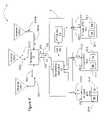
- FIG. 4is a block diagram of one embodiment of a multiplexing apparatus 20 in a system 10 for transceiving radio frequency signals in accordance with the present invention.
- the radio frequency cable 155communicatively couples the multiplexing apparatus 20 to a multiplexer 70 .
- the multiplexer 70is communicatively coupled to a first antenna 160 - 1 and at least two other antennae 160 ( 2 -N).
- the first antenna 160 - 1receives and transmits signals in the first spectral region 310 and the at least two other antennae 160 ( 2 -N) receive and transmit signals in respective portions 312 A, 312 B, and/or 312 C of the second spectral region 312 ( FIG. 3 ).
- the multiplexing apparatus 20is configured as shown in FIG. 1 to include at least two band pass filters 112 ( 1 -N).
- system 10includes the multiplexing apparatus 20 , which is communicatively coupled to the radio frequency cable 155 , at least two base transceiver stations 30 ( 1 - 2 ), and a low noise amplifier 120 .
- system 10includes multiplexing apparatus 20 , the second receiver filter 124 , and low noise amplifier 120 .
- system 10includes multiplexing apparatus 20 , the second receiver filter 124 , low noise amplifier 120 , the cable 155 , a multiplexer 70 , and at least two antennae 160 ( 1 - 2 ).
- system 10includes multiplexing apparatus 20 , the second receiver filter 124 , low noise amplifier 120 , the cable 155 , a multiplexer 70 , at least two antennae 160 ( 1 - 2 ), and at least two base transceiver stations 30 ( 1 - 2 ).
- Each base transceiver station 30 - iincludes a respective transmitter 32 - i and a respective receiver 34 - i .
- the transmitter 32 - i and receiver 34 - i in a base transceiver station 30 - iform a transceiver.
- the radio frequency signals(also referred to herein as “signals”) are represented generally by numerically labeled arrows.
- the radio frequency signals 190 ( 1 -N)are sent from the antennae 160 ( 1 -N) to the multiplexer 70 .
- the multiplexer 70combines the radio frequency signals 190 ( 1 -N) into a combined signal 200 , which is sent to the multiplexing apparatus 20 via the cable 155 .
- the combined signal 200is received at the multiplexing apparatus 20 and is split into a plurality of signals within different frequency bands, which are each sent to a respective one of the base transceiver stations 30 ( 1 -N).
- signal 210 - 1is sent to the first-band base transceiver station 30 - 1
- signal 210 - 2is sent to the second-band base transceiver station 30 - 2
- signal 210 -Nis sent to another second-band base transceiver station 30 -N.
- the multiplexing apparatus 20also receives radio frequency signals from the base transceiver stations 30 ( 1 -N). For example, signal 220 - 1 is sent to the multiplexing apparatus 20 from the first-band base transceiver station 30 - 1 , signal 220 - 2 is sent to the multiplexing apparatus 20 from the second-band base transceiver station 30 - 2 , and signal 220 -N is sent to the multiplexing apparatus 20 from the other second-band base transceiver station 30 -N.
- the signals 220 ( 1 -N)are combined in the multiplexing apparatus 20 and sent to the multiplexer 70 as combined signal 230 via radio frequency cable 155 .
- the multiplexer 70splits the combined signal 230 into signals 240 ( 1 -N), which are sent to the respective antennae 160 ( 1 -N).
- the base transceiver stations 30 ( 1 -N)each transceive a different portion of the spectral region 300 . If there are N base transceiver stations, then (N- 1 ) base transceiver stations are second-band base transceiver stations. In this case, each of the second-band base transceiver stations (such as 30 ( 2 -N)), transceives signals in different portions (such as, 312 A, 312 B, and 312 C) of the second spectral region 312 . For example, as shown in FIG.
- the first-band base transceiver station 30 - 1transceives within the first spectral region 310 at about 1900 MHz
- the second-band base transceiver station 30 - 2transceives within a first portion 312 A of the second spectral region 312 at about 800 MHz
- the third base transceiver station 30 - 3transmits within a second portion 312 B of the second spectral region 312 and receives within a third portion 312 C of the second spectral region 312 .
- the first antenna 160 - 1receives and transmits signals in the first spectral region 310 .
- at least two other antennae 160 ( 2 -N)are configured to receive and transmit signals in a respective portions 312 A, 312 B, and/or 312 C of the second spectral region 312 .
- FIG. 5is a block diagram of one embodiment of a diplexing apparatus 200 in accordance with the present invention.
- the diplexing apparatus 200includes a single band pass filter 112 - 1 , the transmitter filter 126 , and the receiver filter 122 .
- the transmitter path 145 and the receiver path 140are similar in structure and function to the transmitter path 145 and the receiver path 140 described above with reference to FIGS. 1 and 4 .
- FIG. 6is a block diagram of one embodiment of a diplexing apparatus 200 in a radio frequency system 11 in accordance with the present invention.
- the radio frequency cable 155is communicatively coupled the diplexing apparatus 200 to a diplexer 71 and the diplexer 71 is communicatively coupled to a first antenna 160 - 1 and a second antenna 160 - 2 .
- the first antenna 160 - 1receives and transmits signals in the first spectral region 310 and the second antenna 160 - 2 receives and transmits signals in a portion 312 A, 312 B, and/or 312 C of the second spectral region 312 ( FIG. 3 ).
- the diplexing apparatus 200is configured as shown in FIG. 5 to include only one band pass filter 112 - 1 .
- system 11includes the diplexing apparatus 200 , which is communicatively coupled to the radio frequency cable 155 , a first-band base transceiver station 31 - 1 , a second-band base transceiver station 30 - 2 , and a low noise amplifier 120 .
- system 11includes the diplexing apparatus 200 , the second receiver filter 124 , and the low noise amplifier 120 .
- system 11includes the diplexing apparatus 200 , the second receiver filter 124 , the low noise amplifier 120 , the cable 155 , the diplexer 71 , and two antennae 160 ( 1 - 2 ).
- system 11includes the diplexing apparatus 200 , the second receiver filter 124 , the low noise amplifier 120 , the cable 155 , the diplexer 71 , two antennae 160 ( 1 - 2 ), and base transceiver stations 30 ( 1 - 2 ).
- the two base transceiver stations 30 ( 1 - 2 )have the function and structure described above with reference to FIG. 4 .
- the two antennae 160 ( 1 - 2 )also have the function and structure described above with reference to FIG. 4 .
- the radio frequency signals 190 ( 1 - 2 )are sent from the antennae 160 ( 1 - 2 ), respectively, to the diplexer 71 .
- the diplexer 71combines the radio frequency signals 190 ( 1 - 2 ) into a combined signal 201 , which is sent to the diplexing apparatus 200 via the cable 155 .
- the combined signal 201is received at the diplexing apparatus 200 and is split into two signals within two frequency bands.
- Signal 210 - 1is sent to the first-band base transceiver station 30 - 1 and signal 210 - 2 is sent to the second-band base transceiver station 30 - 2 .
- the diplexing apparatus 200also receives radio frequency signals from the base transceiver stations 30 ( 1 - 2 ). For example, signal 220 - 1 is sent to the diplexing apparatus 200 from the first-band base transceiver station 30 - 1 and signal 220 - 2 is sent to the diplexing apparatus 200 from the second-band base transceiver station 30 - 2 .
- the signals 220 ( 1 - 2 )are combined in the diplexing apparatus 200 and sent to the diplexer 71 as combined signal 231 via radio frequency cable 155 .
- the diplexer 71splits the combined signal 231 into signals 240 ( 1 - 2 ) which are sent to the respective antennae 160 ( 1 - 2 ).
- FIG. 7is a flow diagram of one embodiment of a method 700 of receiving signals in a plurality of radio frequency spectral regions, such as 310 , 312 A, and 312 C, in a multiplexing apparatus 20 from a cable 155 .
- Method 700is described with reference to FIGS. 1 and 3 - 6 although method 700 is applicable to other embodiments of the multiplexing apparatus.
- the combined signal 200is received via a radio frequency cable 155 at the multiplexing apparatus 20 .
- the combined signal 200includes signals in the first spectral region 310 and portions 312 A, and 312 C of the second spectral region.
- the combined signal 201includes signals in first spectral region 310 and portion 312 A of the second spectral region and is received via a radio frequency cable 155 at the diplexing apparatus 200 .
- the combined signal 201includes signals in first spectral region 310 and portion 312 C of the second spectral region and is received via a radio frequency cable 155 at the diplexing apparatus 200 .
- the combined signalis split into a signal in a first spectral region and at least one signal in a second spectral region in the multiplexing apparatus.
- each signal in the second spectral region 312is in 312 A or 312 C of the second spectral region 312 .
- the combined signal 200is split into a signal in a first spectral region 310 and at least two signals in a second spectral region at the multiplexing apparatus 20 .
- the combined signal 201is split into one signal in a first spectral region 310 and one signal in a second spectral region 312 in the diplexing apparatus 200 .
- the signal in a first spectral regionis sent from the multiplexing apparatus to a first receiver in a first-band base transceiver station via a receiver filter in the multiplexing apparatus and a low-noise amplifier.
- the signal in the first spectral region 310is sent to a first receiver 34 - 1 in a first-band base transceiver station 30 - 1 via receiver filter 124 in the multiplexing apparatus 20 and the low noise amplifier 120 .
- the at least one signal in a respective at least one portion of the second spectral regionis sent from the multiplexing apparatus to at least one receiver in at least one respective second-band base transceiver station via a respective band pass filter in the multiplexing apparatus.
- the signal in each portion 312 A, and 312 C of the second spectral region 312is sent to an associated receiver 34 - i in an associated second-band base transceiver station 30 - i via an associated band pass filter 112 - i .
- the signal in one of the portion 312 A of the second spectral region 312is sent to a receiver 34 - 2 in the second-band base transceiver station 30 - 2 via the band pass filter 112 - 2 .
- FIG. 8is a flow diagram of one embodiment of a method 800 of receiving signals in a plurality of radio frequency spectral regions, such as 310 and 312 in a multiplexing apparatus 20 and transmitting the signals from the multiplexing apparatus 20 to antennae 160 ( 1 -N) for transmission.
- Method 800is described with reference to FIGS. 1 and 3 - 4 although method 800 is applicable to other embodiments of the multiplexing apparatus.
- Methods 700 and 800together describe a method of transceiving signals in a plurality of radio frequency spectral regions 310 and 312 in a multiplexing apparatus 200 .
- a radio frequency signal 220 - 1 in the first spectral region 310is received from a transmitter 32 - 1 in the first-band base transceiver station 30 - 1 at the multiplexing apparatus 20 .
- at least two signals 220 ( 2 -N) in the respective at least two portions 312 A and 312 B of the second spectral region 312are received from the at least two respective transmitters 32 ( 2 -N) in the at least two second transceiver base stations 30 ( 2 -N) at the multiplexing apparatus 20 .
- the received signal 220 - 1 in the first spectral region 310is combined with the received at least two signals 220 ( 2 -N) in the respective at least two portions 312 A and 312 B of the second spectral region 312 at the multiplexing apparatus 20 .
- the combined signal 230is sent from the multiplexing apparatus 20 via the radio frequency cable 155 .
- a multiplexer 70receives the combined signal 230 from the multiplexing apparatus 20 via the radio frequency cable 155 .
- the multiplexer 70splits the combined signal 230 into the plurality of signals 240 ( 1 -N).
- the signal 240 - 1 in the first spectral region 310is sent from the multiplexer 70 to a first antenna 160 - 1 .
- the at least two signals 240 ( 2 -N) in the at least two portions 312 A and 312 B of the second spectral region 312are sent from the multiplexer 70 to at least two other antennae 160 ( 2 -N).
- the signal in the first spectral region 310is transmitted from the first antenna 160 - 1 responsive to receiving the signal 240 - 1 in the first spectral region 310 from the multiplexer 70 .
- the at least two signalsare transmitted in the respective at least two portions 312 A and 312 B of the second spectral region 312 from the respective at least two other antennae 160 ( 2 -N) responsive to receiving the signals 240 ( 2 -N) in the portions 312 A and 312 B of the second spectral region 312 from the multiplexer 70 .
- FIG. 9is a flow diagram of one embodiment of a method 900 of receiving signals in two radio frequency spectral regions, such as 310 and 312 in a diplexing apparatus 200 and transmitting the signals from the diplexing apparatus 200 to antennae 160 ( 1 -N) for transmission.
- Method 900differs from method 800 in that signals in only one portion of the second spectral region are transceived.
- the multiplexing apparatusis a diplexing apparatus.
- Method 900is described with reference to FIGS. 3 and 5 - 6 although method 900 is applicable to other embodiments of the diplexing apparatus.
- Methods 700 and 900together describe a method of transceiving signals in a plurality of radio frequency spectral regions 310 and 312 in a diplexing apparatus 2000 .
- a radio frequency signal 220 - 1 in the first spectral region 310is received from a transmitter 32 - 1 in the first-band base transceiver station 30 - 1 at the diplexing apparatus 200 .
- signal 220 - 2 in the second spectral region 312is received from the transmitter 32 - 2 in the second transceiver base station 30 - 2 at the diplexing apparatus 200 .
- the signals 220 - 2are all within one portion of the spectral region 312 .
- the received signal 220 - 1 in the first spectral region 310is combined with the received signal 220 - 2 in the second spectral region 312 at the diplexing apparatus 200 .
- the combined signal 230is sent from the diplexing apparatus 200 via the radio frequency cable 155 .
- a diplexer 71receives the combined signal 230 from the diplexing apparatus 200 via the radio frequency cable 155 .
- the diplexer 71splits the combined signal 230 into two signals 240 ( 1 - 2 ).
- the signal 240 - 1 in the first spectral region 310is sent from the diplexer 71 to a first antenna 160 - 1 .
- the signal 240 - 2 in the second spectral region 312is sent from the diplexer 71 to the other antenna 160 - 2 .
- the signal in the first spectral region 310is transmitted from the first antenna 160 - 1 responsive to receiving the signal 240 - 1 in the first spectral region 310 from the diplexer 71 .
- the signal in the second spectral region 312is transmitted from the other antenna 160 - 2 responsive to receiving the signal 240 - 2 in the second spectral region 312 from the diplexer 71 .
Landscapes
- Engineering & Computer Science (AREA)
- Signal Processing (AREA)
- Computer Networks & Wireless Communication (AREA)
- Transceivers (AREA)
Abstract
Description
Claims (9)
Priority Applications (3)
| Application Number | Priority Date | Filing Date | Title |
|---|---|---|---|
| US11/943,724US7701887B2 (en) | 2007-11-21 | 2007-11-21 | Multiplexing apparatus in a transceiver system |
| PCT/US2008/084023WO2009067506A2 (en) | 2007-11-21 | 2008-11-19 | Multiplexing apparatus in a transceiver system |
| US12/707,921US8031647B2 (en) | 2007-11-21 | 2010-02-18 | Multiplexing apparatus in a transceiver system |
Applications Claiming Priority (1)
| Application Number | Priority Date | Filing Date | Title |
|---|---|---|---|
| US11/943,724US7701887B2 (en) | 2007-11-21 | 2007-11-21 | Multiplexing apparatus in a transceiver system |
Related Child Applications (1)
| Application Number | Title | Priority Date | Filing Date |
|---|---|---|---|
| US12/707,921ContinuationUS8031647B2 (en) | 2007-11-21 | 2010-02-18 | Multiplexing apparatus in a transceiver system |
Publications (2)
| Publication Number | Publication Date |
|---|---|
| US20090129299A1 US20090129299A1 (en) | 2009-05-21 |
| US7701887B2true US7701887B2 (en) | 2010-04-20 |
Family
ID=40641857
Family Applications (2)
| Application Number | Title | Priority Date | Filing Date |
|---|---|---|---|
| US11/943,724Active2028-08-21US7701887B2 (en) | 2007-11-21 | 2007-11-21 | Multiplexing apparatus in a transceiver system |
| US12/707,921ActiveUS8031647B2 (en) | 2007-11-21 | 2010-02-18 | Multiplexing apparatus in a transceiver system |
Family Applications After (1)
| Application Number | Title | Priority Date | Filing Date |
|---|---|---|---|
| US12/707,921ActiveUS8031647B2 (en) | 2007-11-21 | 2010-02-18 | Multiplexing apparatus in a transceiver system |
Country Status (2)
| Country | Link |
|---|---|
| US (2) | US7701887B2 (en) |
| WO (1) | WO2009067506A2 (en) |
Families Citing this family (3)
| Publication number | Priority date | Publication date | Assignee | Title |
|---|---|---|---|---|
| US9548852B2 (en)* | 2014-09-04 | 2017-01-17 | Commscope Technologies Llc | Antenna cross connect scheme for LTE |
| CN106911355B (en)* | 2017-03-03 | 2019-06-18 | 上海华为技术有限公司 | A kind of signal transmitting apparatus, signal transmission system and method |
| CN114830436A (en)* | 2019-12-18 | 2022-07-29 | 康普技术有限责任公司 | Base station antenna unit having array spanning multiple antennas connected by jumper cables |
Citations (13)
| Publication number | Priority date | Publication date | Assignee | Title |
|---|---|---|---|---|
| US5502715A (en)* | 1995-03-16 | 1996-03-26 | Penny; James R. | Integrated diplexer-amplifier for near antenna installation |
| US5969837A (en) | 1996-12-15 | 1999-10-19 | Foxcom Wireless Ltd. | Communications system |
| US6269255B1 (en)* | 1997-10-21 | 2001-07-31 | Interwave Communications International, Ltd. | Self-contained masthead units for cellular communication networks |
| KR20020011638A (en) | 2000-08-03 | 2002-02-09 | 김대기 | Method and system of optical-repeating for muti-frequency bands |
| US6640111B1 (en)* | 1997-03-03 | 2003-10-28 | Celletra Ltd. | Cellular communications systems |
| US6658263B1 (en)* | 1999-12-21 | 2003-12-02 | Lucent Technologies Inc. | Wireless system combining arrangement and method thereof |
| US6823003B2 (en)* | 2001-01-15 | 2004-11-23 | Infineon Technologies Ag | Multi-path transceiver amplification apparatus, method and system |
| US6892056B1 (en)* | 1999-07-29 | 2005-05-10 | Alexandr Vasilievich Garmanov | Subscriber station with duplex antenna amplifier |
| US6957047B1 (en)* | 1999-02-18 | 2005-10-18 | Ydi Wireless, Inc. | Bi-directional switched RF amplifier, waterproof housing, electrostatic overvoltage protection device, and mounting bracket therefor |
| KR20060101052A (en) | 2005-03-18 | 2006-09-22 | 주식회사 케이엠더블유 | Base Station Antenna Cable Common Device |
| US7120465B2 (en)* | 2003-12-20 | 2006-10-10 | Telefonaktiebolaget Lm Ericsson (Publ) | Transceiver system including multiple radio base stations that share an antenna |
| US7123939B1 (en)* | 1999-02-05 | 2006-10-17 | Interdigital Technology Corporation | Communication station with automatic cable loss compensation |
| US7532861B2 (en)* | 2004-12-23 | 2009-05-12 | Microsoft Corporation | Connection interface for conveying RF, data, and power between electronic devices |
Family Cites Families (2)
| Publication number | Priority date | Publication date | Assignee | Title |
|---|---|---|---|---|
| US6858263B2 (en)* | 2002-02-07 | 2005-02-22 | Daiwa Techno Systems Co., Ltd. | Method of manufacturing aperture plate |
| GB0622435D0 (en)* | 2006-11-10 | 2006-12-20 | Quintel Technology Ltd | Electrically tilted antenna system with polarisation diversity |
- 2007
- 2007-11-21USUS11/943,724patent/US7701887B2/enactiveActive
- 2008
- 2008-11-19WOPCT/US2008/084023patent/WO2009067506A2/enactiveApplication Filing
- 2010
- 2010-02-18USUS12/707,921patent/US8031647B2/enactiveActive
Patent Citations (13)
| Publication number | Priority date | Publication date | Assignee | Title |
|---|---|---|---|---|
| US5502715A (en)* | 1995-03-16 | 1996-03-26 | Penny; James R. | Integrated diplexer-amplifier for near antenna installation |
| US5969837A (en) | 1996-12-15 | 1999-10-19 | Foxcom Wireless Ltd. | Communications system |
| US6640111B1 (en)* | 1997-03-03 | 2003-10-28 | Celletra Ltd. | Cellular communications systems |
| US6269255B1 (en)* | 1997-10-21 | 2001-07-31 | Interwave Communications International, Ltd. | Self-contained masthead units for cellular communication networks |
| US7123939B1 (en)* | 1999-02-05 | 2006-10-17 | Interdigital Technology Corporation | Communication station with automatic cable loss compensation |
| US6957047B1 (en)* | 1999-02-18 | 2005-10-18 | Ydi Wireless, Inc. | Bi-directional switched RF amplifier, waterproof housing, electrostatic overvoltage protection device, and mounting bracket therefor |
| US6892056B1 (en)* | 1999-07-29 | 2005-05-10 | Alexandr Vasilievich Garmanov | Subscriber station with duplex antenna amplifier |
| US6658263B1 (en)* | 1999-12-21 | 2003-12-02 | Lucent Technologies Inc. | Wireless system combining arrangement and method thereof |
| KR20020011638A (en) | 2000-08-03 | 2002-02-09 | 김대기 | Method and system of optical-repeating for muti-frequency bands |
| US6823003B2 (en)* | 2001-01-15 | 2004-11-23 | Infineon Technologies Ag | Multi-path transceiver amplification apparatus, method and system |
| US7120465B2 (en)* | 2003-12-20 | 2006-10-10 | Telefonaktiebolaget Lm Ericsson (Publ) | Transceiver system including multiple radio base stations that share an antenna |
| US7532861B2 (en)* | 2004-12-23 | 2009-05-12 | Microsoft Corporation | Connection interface for conveying RF, data, and power between electronic devices |
| KR20060101052A (en) | 2005-03-18 | 2006-09-22 | 주식회사 케이엠더블유 | Base Station Antenna Cable Common Device |
Non-Patent Citations (1)
| Title |
|---|
| International Searching Authority, "International Search Report", Jun. 26, 2009, Published in: WO. |
Also Published As
| Publication number | Publication date |
|---|---|
| US20090129299A1 (en) | 2009-05-21 |
| US8031647B2 (en) | 2011-10-04 |
| US20100142420A1 (en) | 2010-06-10 |
| WO2009067506A2 (en) | 2009-05-28 |
| WO2009067506A3 (en) | 2009-08-13 |
Similar Documents
| Publication | Publication Date | Title |
|---|---|---|
| US10615839B2 (en) | High-frequency-signal transceiver circuit | |
| US7729726B2 (en) | Feeder cable reduction | |
| US6445904B1 (en) | Repeater diversity system | |
| US20210195388A1 (en) | Vehicle-mounted transmission system | |
| CN102315880A (en) | Light path transmission method and device | |
| US5857012A (en) | Radio telephone base station with a monitoring apparatus | |
| US7701887B2 (en) | Multiplexing apparatus in a transceiver system | |
| US20080248772A1 (en) | Integrated Aviation Rf Receiver Front End and Antenna Method and Apparatus | |
| US20070135169A1 (en) | Feeder cable reduction | |
| US8315670B2 (en) | Base station antenna interface system for antenna cable reduction in dual band deployments | |
| US20170207534A1 (en) | Antenna interface for transmission line trace | |
| EP2660975A1 (en) | Tower mounted amplifier and method of use thereof | |
| US9025644B2 (en) | Transmitting/receiving system | |
| US10594341B2 (en) | High-frequency-signal transceiver circuit | |
| CA2962561C (en) | Fixed intermediate frequency signal with tuned low frequency local oscillator reference for linear transmitter | |
| KR20200003042A (en) | Communication module | |
| US11394411B2 (en) | Transmitting/receiving system for radio signals having an integrated transmission amplifier protection function | |
| US10059355B2 (en) | Communication device for rail vehicle, rail vehicle equipped with said device | |
| KR20160112131A (en) | Apparatus for suppressing multi-band pimd of mobile communication and method using the same | |
| CN213638235U (en) | Special small base station board for LTE mining | |
| KR200304926Y1 (en) | An apparatus for sharing with antenna feeder of mobile communications | |
| US12267144B2 (en) | Antenna device, integrated communication device, and wireless communication device | |
| CN113692709B (en) | Antenna device for transmitting high-frequency signals from or to a motor vehicle and motor vehicle having an antenna device | |
| EP3403334B1 (en) | Tower mounted amplifier and method of use thereof | |
| EP2560289A2 (en) | Combining apparatus |
Legal Events
| Date | Code | Title | Description |
|---|---|---|---|
| AS | Assignment | Owner name:ADC TELECOMMUNICATIONS, INC., MINNESOTA Free format text:ASSIGNMENT OF ASSIGNORS INTEREST;ASSIGNORS:HEUER, WILLIAM C.;KASAHARA, YOSHI;REEL/FRAME:020145/0941 Effective date:20071120 Owner name:ADC TELECOMMUNICATIONS, INC.,MINNESOTA Free format text:ASSIGNMENT OF ASSIGNORS INTEREST;ASSIGNORS:HEUER, WILLIAM C.;KASAHARA, YOSHI;REEL/FRAME:020145/0941 Effective date:20071120 | |
| STCF | Information on status: patent grant | Free format text:PATENTED CASE | |
| FPAY | Fee payment | Year of fee payment:4 | |
| AS | Assignment | Owner name:TYCO ELECTRONICS SERVICES GMBH, SWITZERLAND Free format text:ASSIGNMENT OF ASSIGNORS INTEREST;ASSIGNOR:ADC TELECOMMUNICATIONS, INC.;REEL/FRAME:036060/0174 Effective date:20110930 | |
| AS | Assignment | Owner name:COMMSCOPE EMEA LIMITED, IRELAND Free format text:ASSIGNMENT OF ASSIGNORS INTEREST;ASSIGNOR:TYCO ELECTRONICS SERVICES GMBH;REEL/FRAME:036956/0001 Effective date:20150828 | |
| AS | Assignment | Owner name:COMMSCOPE TECHNOLOGIES LLC, NORTH CAROLINA Free format text:ASSIGNMENT OF ASSIGNORS INTEREST;ASSIGNOR:COMMSCOPE EMEA LIMITED;REEL/FRAME:037012/0001 Effective date:20150828 | |
| AS | Assignment | Owner name:JPMORGAN CHASE BANK, N.A., AS COLLATERAL AGENT, ILLINOIS Free format text:PATENT SECURITY AGREEMENT (TERM);ASSIGNOR:COMMSCOPE TECHNOLOGIES LLC;REEL/FRAME:037513/0709 Effective date:20151220 Owner name:JPMORGAN CHASE BANK, N.A., AS COLLATERAL AGENT, ILLINOIS Free format text:PATENT SECURITY AGREEMENT (ABL);ASSIGNOR:COMMSCOPE TECHNOLOGIES LLC;REEL/FRAME:037514/0196 Effective date:20151220 Owner name:JPMORGAN CHASE BANK, N.A., AS COLLATERAL AGENT, IL Free format text:PATENT SECURITY AGREEMENT (TERM);ASSIGNOR:COMMSCOPE TECHNOLOGIES LLC;REEL/FRAME:037513/0709 Effective date:20151220 Owner name:JPMORGAN CHASE BANK, N.A., AS COLLATERAL AGENT, IL Free format text:PATENT SECURITY AGREEMENT (ABL);ASSIGNOR:COMMSCOPE TECHNOLOGIES LLC;REEL/FRAME:037514/0196 Effective date:20151220 | |
| MAFP | Maintenance fee payment | Free format text:PAYMENT OF MAINTENANCE FEE, 8TH YEAR, LARGE ENTITY (ORIGINAL EVENT CODE: M1552) Year of fee payment:8 | |
| AS | Assignment | Owner name:COMMSCOPE TECHNOLOGIES LLC, NORTH CAROLINA Free format text:RELEASE BY SECURED PARTY;ASSIGNOR:JPMORGAN CHASE BANK, N.A.;REEL/FRAME:048840/0001 Effective date:20190404 Owner name:ANDREW LLC, NORTH CAROLINA Free format text:RELEASE BY SECURED PARTY;ASSIGNOR:JPMORGAN CHASE BANK, N.A.;REEL/FRAME:048840/0001 Effective date:20190404 Owner name:COMMSCOPE, INC. OF NORTH CAROLINA, NORTH CAROLINA Free format text:RELEASE BY SECURED PARTY;ASSIGNOR:JPMORGAN CHASE BANK, N.A.;REEL/FRAME:048840/0001 Effective date:20190404 Owner name:REDWOOD SYSTEMS, INC., NORTH CAROLINA Free format text:RELEASE BY SECURED PARTY;ASSIGNOR:JPMORGAN CHASE BANK, N.A.;REEL/FRAME:048840/0001 Effective date:20190404 Owner name:ALLEN TELECOM LLC, ILLINOIS Free format text:RELEASE BY SECURED PARTY;ASSIGNOR:JPMORGAN CHASE BANK, N.A.;REEL/FRAME:048840/0001 Effective date:20190404 Owner name:REDWOOD SYSTEMS, INC., NORTH CAROLINA Free format text:RELEASE BY SECURED PARTY;ASSIGNOR:JPMORGAN CHASE BANK, N.A.;REEL/FRAME:049260/0001 Effective date:20190404 Owner name:ALLEN TELECOM LLC, ILLINOIS Free format text:RELEASE BY SECURED PARTY;ASSIGNOR:JPMORGAN CHASE BANK, N.A.;REEL/FRAME:049260/0001 Effective date:20190404 Owner name:ANDREW LLC, NORTH CAROLINA Free format text:RELEASE BY SECURED PARTY;ASSIGNOR:JPMORGAN CHASE BANK, N.A.;REEL/FRAME:049260/0001 Effective date:20190404 Owner name:COMMSCOPE TECHNOLOGIES LLC, NORTH CAROLINA Free format text:RELEASE BY SECURED PARTY;ASSIGNOR:JPMORGAN CHASE BANK, N.A.;REEL/FRAME:049260/0001 Effective date:20190404 Owner name:COMMSCOPE, INC. OF NORTH CAROLINA, NORTH CAROLINA Free format text:RELEASE BY SECURED PARTY;ASSIGNOR:JPMORGAN CHASE BANK, N.A.;REEL/FRAME:049260/0001 Effective date:20190404 | |
| AS | Assignment | Owner name:JPMORGAN CHASE BANK, N.A., NEW YORK Free format text:TERM LOAN SECURITY AGREEMENT;ASSIGNORS:COMMSCOPE, INC. OF NORTH CAROLINA;COMMSCOPE TECHNOLOGIES LLC;ARRIS ENTERPRISES LLC;AND OTHERS;REEL/FRAME:049905/0504 Effective date:20190404 Owner name:WILMINGTON TRUST, NATIONAL ASSOCIATION, AS COLLATE Free format text:PATENT SECURITY AGREEMENT;ASSIGNOR:COMMSCOPE TECHNOLOGIES LLC;REEL/FRAME:049892/0051 Effective date:20190404 Owner name:JPMORGAN CHASE BANK, N.A., NEW YORK Free format text:ABL SECURITY AGREEMENT;ASSIGNORS:COMMSCOPE, INC. OF NORTH CAROLINA;COMMSCOPE TECHNOLOGIES LLC;ARRIS ENTERPRISES LLC;AND OTHERS;REEL/FRAME:049892/0396 Effective date:20190404 Owner name:WILMINGTON TRUST, NATIONAL ASSOCIATION, AS COLLATERAL AGENT, CONNECTICUT Free format text:PATENT SECURITY AGREEMENT;ASSIGNOR:COMMSCOPE TECHNOLOGIES LLC;REEL/FRAME:049892/0051 Effective date:20190404 | |
| MAFP | Maintenance fee payment | Free format text:PAYMENT OF MAINTENANCE FEE, 12TH YEAR, LARGE ENTITY (ORIGINAL EVENT CODE: M1553); ENTITY STATUS OF PATENT OWNER: LARGE ENTITY Year of fee payment:12 | |
| AS | Assignment | Owner name:WILMINGTON TRUST, DELAWARE Free format text:SECURITY INTEREST;ASSIGNORS:ARRIS SOLUTIONS, INC.;ARRIS ENTERPRISES LLC;COMMSCOPE TECHNOLOGIES LLC;AND OTHERS;REEL/FRAME:060752/0001 Effective date:20211115 | |
| AS | Assignment | Owner name:STRONG FORCE IOT PORTFOLIO 2016, LLC, FLORIDA Free format text:ASSIGNMENT OF ASSIGNORS INTEREST;ASSIGNOR:COMMSCOPE TECHNOLOGIES LLC;REEL/FRAME:059559/0172 Effective date:20220317 | |
| AS | Assignment | Owner name:ARRIS ENTERPRISES LLC, NORTH CAROLINA Free format text:PARTIAL RELEASE OF ABL SECURITY INTEREST;ASSIGNOR:JPMORGAN CHASE BANK, N.A.;REEL/FRAME:060073/0483 Effective date:20220513 Owner name:COMMSCOPE TECHNOLOGIES LLC, NORTH CAROLINA Free format text:PARTIAL RELEASE OF ABL SECURITY INTEREST;ASSIGNOR:JPMORGAN CHASE BANK, N.A.;REEL/FRAME:060073/0483 Effective date:20220513 Owner name:ARRIS ENTERPRISES LLC, NORTH CAROLINA Free format text:PARTIAL RELEASE OF TERM LOAN SECURITY INTEREST;ASSIGNOR:JPMORGAN CHASE BANK, N.A.;REEL/FRAME:060073/0399 Effective date:20220513 Owner name:COMMSCOPE TECHNOLOGIES LLC, NORTH CAROLINA Free format text:PARTIAL RELEASE OF TERM LOAN SECURITY INTEREST;ASSIGNOR:JPMORGAN CHASE BANK, N.A.;REEL/FRAME:060073/0399 Effective date:20220513 | |
| AS | Assignment | Owner name:COMMSCOPE TECHNOLOGIES LLC, NORTH CAROLINA Free format text:PARTIAL TERMINATION AND RELEASE OF SECURITY INTEREST IN PATENTS;ASSIGNOR:WILMINGTON TRUST, NATIONAL ASSOCIATION, AS COLLATERAL AGENT;REEL/FRAME:060163/0662 Effective date:20220513 | |
| AS | Assignment | Owner name:RUCKUS WIRELESS, LLC (F/K/A RUCKUS WIRELESS, INC.), NORTH CAROLINA Free format text:RELEASE OF SECURITY INTEREST AT REEL/FRAME 049905/0504;ASSIGNOR:JPMORGAN CHASE BANK, N.A., AS COLLATERAL AGENT;REEL/FRAME:071477/0255 Effective date:20241217 Owner name:COMMSCOPE TECHNOLOGIES LLC, NORTH CAROLINA Free format text:RELEASE OF SECURITY INTEREST AT REEL/FRAME 049905/0504;ASSIGNOR:JPMORGAN CHASE BANK, N.A., AS COLLATERAL AGENT;REEL/FRAME:071477/0255 Effective date:20241217 Owner name:COMMSCOPE, INC. OF NORTH CAROLINA, NORTH CAROLINA Free format text:RELEASE OF SECURITY INTEREST AT REEL/FRAME 049905/0504;ASSIGNOR:JPMORGAN CHASE BANK, N.A., AS COLLATERAL AGENT;REEL/FRAME:071477/0255 Effective date:20241217 Owner name:ARRIS SOLUTIONS, INC., NORTH CAROLINA Free format text:RELEASE OF SECURITY INTEREST AT REEL/FRAME 049905/0504;ASSIGNOR:JPMORGAN CHASE BANK, N.A., AS COLLATERAL AGENT;REEL/FRAME:071477/0255 Effective date:20241217 Owner name:ARRIS TECHNOLOGY, INC., NORTH CAROLINA Free format text:RELEASE OF SECURITY INTEREST AT REEL/FRAME 049905/0504;ASSIGNOR:JPMORGAN CHASE BANK, N.A., AS COLLATERAL AGENT;REEL/FRAME:071477/0255 Effective date:20241217 Owner name:ARRIS ENTERPRISES LLC (F/K/A ARRIS ENTERPRISES, INC.), NORTH CAROLINA Free format text:RELEASE OF SECURITY INTEREST AT REEL/FRAME 049905/0504;ASSIGNOR:JPMORGAN CHASE BANK, N.A., AS COLLATERAL AGENT;REEL/FRAME:071477/0255 Effective date:20241217 |