US7701858B2 - Method and apparatus for wireless communication in a mesh network - Google Patents
Method and apparatus for wireless communication in a mesh networkDownload PDFInfo
- Publication number
- US7701858B2 US7701858B2US10/836,103US83610304AUS7701858B2US 7701858 B2US7701858 B2US 7701858B2US 83610304 AUS83610304 AUS 83610304AUS 7701858 B2US7701858 B2US 7701858B2
- Authority
- US
- United States
- Prior art keywords
- node
- network
- router
- communication
- routers
- Prior art date
- Legal status (The legal status is an assumption and is not a legal conclusion. Google has not performed a legal analysis and makes no representation as to the accuracy of the status listed.)
- Expired - Fee Related, expires
Links
Images


Classifications
- H—ELECTRICITY
- H04—ELECTRIC COMMUNICATION TECHNIQUE
- H04L—TRANSMISSION OF DIGITAL INFORMATION, e.g. TELEGRAPHIC COMMUNICATION
- H04L9/00—Cryptographic mechanisms or cryptographic arrangements for secret or secure communications; Network security protocols
- H04L9/08—Key distribution or management, e.g. generation, sharing or updating, of cryptographic keys or passwords
- H04L9/0816—Key establishment, i.e. cryptographic processes or cryptographic protocols whereby a shared secret becomes available to two or more parties, for subsequent use
- H04L9/0819—Key transport or distribution, i.e. key establishment techniques where one party creates or otherwise obtains a secret value, and securely transfers it to the other(s)
- H04L9/0825—Key transport or distribution, i.e. key establishment techniques where one party creates or otherwise obtains a secret value, and securely transfers it to the other(s) using asymmetric-key encryption or public key infrastructure [PKI], e.g. key signature or public key certificates
- H—ELECTRICITY
- H04—ELECTRIC COMMUNICATION TECHNIQUE
- H04L—TRANSMISSION OF DIGITAL INFORMATION, e.g. TELEGRAPHIC COMMUNICATION
- H04L5/00—Arrangements affording multiple use of the transmission path
- H04L5/003—Arrangements for allocating sub-channels of the transmission path
- H04L5/0037—Inter-user or inter-terminal allocation
- H—ELECTRICITY
- H04—ELECTRIC COMMUNICATION TECHNIQUE
- H04L—TRANSMISSION OF DIGITAL INFORMATION, e.g. TELEGRAPHIC COMMUNICATION
- H04L9/00—Cryptographic mechanisms or cryptographic arrangements for secret or secure communications; Network security protocols
- H04L9/08—Key distribution or management, e.g. generation, sharing or updating, of cryptographic keys or passwords
- H04L9/0816—Key establishment, i.e. cryptographic processes or cryptographic protocols whereby a shared secret becomes available to two or more parties, for subsequent use
- H04L9/0819—Key transport or distribution, i.e. key establishment techniques where one party creates or otherwise obtains a secret value, and securely transfers it to the other(s)
- H04L9/083—Key transport or distribution, i.e. key establishment techniques where one party creates or otherwise obtains a secret value, and securely transfers it to the other(s) involving central third party, e.g. key distribution center [KDC] or trusted third party [TTP]
- H—ELECTRICITY
- H04—ELECTRIC COMMUNICATION TECHNIQUE
- H04L—TRANSMISSION OF DIGITAL INFORMATION, e.g. TELEGRAPHIC COMMUNICATION
- H04L9/00—Cryptographic mechanisms or cryptographic arrangements for secret or secure communications; Network security protocols
- H04L9/14—Cryptographic mechanisms or cryptographic arrangements for secret or secure communications; Network security protocols using a plurality of keys or algorithms
- H04L9/16—Cryptographic mechanisms or cryptographic arrangements for secret or secure communications; Network security protocols using a plurality of keys or algorithms the keys or algorithms being changed during operation
- H—ELECTRICITY
- H04—ELECTRIC COMMUNICATION TECHNIQUE
- H04L—TRANSMISSION OF DIGITAL INFORMATION, e.g. TELEGRAPHIC COMMUNICATION
- H04L9/00—Cryptographic mechanisms or cryptographic arrangements for secret or secure communications; Network security protocols
- H04L9/32—Cryptographic mechanisms or cryptographic arrangements for secret or secure communications; Network security protocols including means for verifying the identity or authority of a user of the system or for message authentication, e.g. authorization, entity authentication, data integrity or data verification, non-repudiation, key authentication or verification of credentials
- H04L9/3247—Cryptographic mechanisms or cryptographic arrangements for secret or secure communications; Network security protocols including means for verifying the identity or authority of a user of the system or for message authentication, e.g. authorization, entity authentication, data integrity or data verification, non-repudiation, key authentication or verification of credentials involving digital signatures
- H—ELECTRICITY
- H04—ELECTRIC COMMUNICATION TECHNIQUE
- H04W—WIRELESS COMMUNICATION NETWORKS
- H04W12/00—Security arrangements; Authentication; Protecting privacy or anonymity
- H04W12/06—Authentication
- H04W12/069—Authentication using certificates or pre-shared keys
- H—ELECTRICITY
- H04—ELECTRIC COMMUNICATION TECHNIQUE
- H04W—WIRELESS COMMUNICATION NETWORKS
- H04W24/00—Supervisory, monitoring or testing arrangements
- H04W24/02—Arrangements for optimising operational condition
- H—ELECTRICITY
- H04—ELECTRIC COMMUNICATION TECHNIQUE
- H04W—WIRELESS COMMUNICATION NETWORKS
- H04W52/00—Power management, e.g. Transmission Power Control [TPC] or power classes
- H04W52/02—Power saving arrangements
- H04W52/0209—Power saving arrangements in terminal devices
- H04W52/0212—Power saving arrangements in terminal devices managed by the network, e.g. network or access point is leader and terminal is follower
- H04W52/0216—Power saving arrangements in terminal devices managed by the network, e.g. network or access point is leader and terminal is follower using a pre-established activity schedule, e.g. traffic indication frame
- H—ELECTRICITY
- H04—ELECTRIC COMMUNICATION TECHNIQUE
- H04W—WIRELESS COMMUNICATION NETWORKS
- H04W52/00—Power management, e.g. Transmission Power Control [TPC] or power classes
- H04W52/02—Power saving arrangements
- H04W52/0209—Power saving arrangements in terminal devices
- H04W52/0212—Power saving arrangements in terminal devices managed by the network, e.g. network or access point is leader and terminal is follower
- H04W52/0219—Power saving arrangements in terminal devices managed by the network, e.g. network or access point is leader and terminal is follower where the power saving management affects multiple terminals
- H—ELECTRICITY
- H04—ELECTRIC COMMUNICATION TECHNIQUE
- H04W—WIRELESS COMMUNICATION NETWORKS
- H04W84/00—Network topologies
- H04W84/18—Self-organising networks, e.g. ad-hoc networks or sensor networks
- H—ELECTRICITY
- H04—ELECTRIC COMMUNICATION TECHNIQUE
- H04L—TRANSMISSION OF DIGITAL INFORMATION, e.g. TELEGRAPHIC COMMUNICATION
- H04L2209/00—Additional information or applications relating to cryptographic mechanisms or cryptographic arrangements for secret or secure communication H04L9/00
- H04L2209/80—Wireless
- H04L2209/805—Lightweight hardware, e.g. radio-frequency identification [RFID] or sensor
- H—ELECTRICITY
- H04—ELECTRIC COMMUNICATION TECHNIQUE
- H04W—WIRELESS COMMUNICATION NETWORKS
- H04W48/00—Access restriction; Network selection; Access point selection
- H04W48/16—Discovering, processing access restriction or access information
- H—ELECTRICITY
- H04—ELECTRIC COMMUNICATION TECHNIQUE
- H04W—WIRELESS COMMUNICATION NETWORKS
- H04W8/00—Network data management
- H04W8/005—Discovery of network devices, e.g. terminals
- Y—GENERAL TAGGING OF NEW TECHNOLOGICAL DEVELOPMENTS; GENERAL TAGGING OF CROSS-SECTIONAL TECHNOLOGIES SPANNING OVER SEVERAL SECTIONS OF THE IPC; TECHNICAL SUBJECTS COVERED BY FORMER USPC CROSS-REFERENCE ART COLLECTIONS [XRACs] AND DIGESTS
- Y02—TECHNOLOGIES OR APPLICATIONS FOR MITIGATION OR ADAPTATION AGAINST CLIMATE CHANGE
- Y02D—CLIMATE CHANGE MITIGATION TECHNOLOGIES IN INFORMATION AND COMMUNICATION TECHNOLOGIES [ICT], I.E. INFORMATION AND COMMUNICATION TECHNOLOGIES AIMING AT THE REDUCTION OF THEIR OWN ENERGY USE
- Y02D30/00—Reducing energy consumption in communication networks
- Y02D30/70—Reducing energy consumption in communication networks in wireless communication networks
Definitions
- This inventionrelates to wireless communication networks in which wireless communication devices are active and send wireless information to each other and/or a host computer.
- WSNsWireless Sensor Networks
- Such networkshave a variety of potential applications.
- WSNsmay be used to detect soil moisture levels in plant nurseries, resulting in the automated activation of fans (when the environment is too hot) or sprinklers (when soil is too dry).
- WSNsmay be used to log unauthorized handling of sensitive or expensive items such as computer equipment or artwork, or to track vehicles in a large parking lot, or for a wide variety of other applications.
- a wireless sensor networkincludes a plurality of Star nodes constructed and arranged to transmit and receive wireless signals. At least one of the Star nodes is associated with at least one corresponding sensor device and is constructed and arranged to transmit a wireless signal including information from the corresponding sensor device.
- a plurality of Routersis each constructed and arranged to transmit and receive wireless signals for communication with at least one Star node and is constructed and arranged to transmit and receive wireless signals for communication with at least one other device in the network.
- Each of the plurality of Star nodescommunicates with at least one Router using multiple frequencies. The Routers are each available for communication with at least one Star node for a period that begins at a randomized time or at a randomized frequency.
- a wireless sensor networkincludes a plurality of Star nodes constructed and arranged to transmit and receive wireless signals. At least one of the Star nodes is associated with at least one corresponding sensor device and is constructed and arranged to transmit a wireless signal including information from the corresponding sensor device.
- a plurality of Routersis each constructed and arranged to transmit and receive wireless signals for communication with at least one Star node and is constructed and arranged to transmit and receive wireless signals for communication with at least one other device in the network.
- At least one Star node or at least one Routerperforms a connectivity assessment that indicates a measure of a quality of wireless communication between the at least one Star node or the at least one Router and at least one other device in the network. The connectivity assessment is used to determine a communication relationship between the at least one Star node or at least one Router and the at least one other device.
- a wireless sensor networkincludes a plurality of Star nodes constructed and arranged to transmit and receive wireless signals. At least one of the Star nodes is associated with at least one corresponding sensor device and is constructed and arranged to transmit a wireless signal including information from the corresponding sensor device.
- a plurality of Routersis each constructed and arranged to transmit and receive wireless signals for communication with at least one Star node and is constructed and arranged to transmit and receive wireless signals for communication with at least one other device in the network.
- a Host computercommunicates with the plurality of Routers at least in part via wireless signals. The Host computer includes a set of software proxies that include status information consistent with the current status of the plurality of Star nodes and the plurality of Routers.
- aspects of the inventionalso relate to a method for communication in a wireless sensor network.
- one or more routers in a networkmay be available for communication with one or more star nodes at a randomized time and/or a randomized frequency.
- a connectivity assessmentmay be performed to evaluate the quality of communications between one or more star nodes, or one or more routers, in the network, and at least one other device in the network. Based on the connectivity assessment, communication relationships may be formed. The connectivity assessment may be performed at several different frequencies and/or at different times. Primary and secondary communication relationships may be formed between devices in the network to provide for system redundancy.
- one or more proxiesmay be maintained for a wireless sensor network where each proxy includes or represents a status of one or more devices in the network, e.g., one or more star nodes or routers.
- Proxiesmay be used to handle information requests and/or status change requests for the network, e.g., a proxy may be requested to change a communication relationship between devices in the network and may generate command signals to cause the corresponding devices to make the corresponding change.
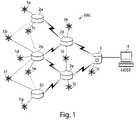
- FIG. 1shows an example of a Wireless Sensor Network (WSN) in accordance with the invention.
- WSNWireless Sensor Network
- FIG. 2shows an overview of a system configured according to the invention.
- FIG. 3illustrates the process of a node joining a WSN.
- FIG. 4shows an example of a WSN with a simple hub-and-spoke configuration.
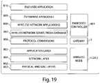
- FIG. 5shows an overview of the layered structure of a WSN according to the invention.
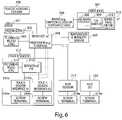
- FIG. 6is a block diagram of a WSN node.
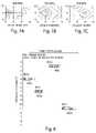
- FIG. 7illustrates the effect of changing frequency on a radio environment.
- FIG. 8illustrates transmission of Frame Beacons and Contention Access Periods at different frequencies over time.
- FIG. 9illustrates transmission of the FH Beacon on the previous channel using a portion of Hop Sequence A as an example.
- FIG. 10illustrates a hybrid authentication/encryption scheme in a WSN.
- FIG. 11shows the uncertainty that may be accounted for by a node in forecasting Beacon timing.
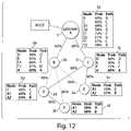
- FIG. 12illustrates the chaining of Connectivity Assessments and the use of routing tables with probabilities.
- FIG. 13shows an embodiment of packet structure in a WSN.
- FIG. 14illustrates a send/retry strategy for messages from a node to the Host in a WSN.
- FIG. 15illustrates a method for message forwarding without involving the Host.
- FIG. 16illustrates how a WSN may be restructured if a Router is lost vis-à-vis the network.
- FIG. 17illustrates the chaining of Connectivity Assessments and the use of routing tables with probabilities in a WSN with more than one Gateway.
- FIG. 18illustrates one embodiment of a WSN architecture.
- FIG. 19shows an overview of some elements that may be present in a WSN.
- FIG. 20shows an embodiment of a WSN controller.
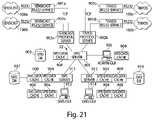
- FIG. 21shows an embodiment of a proxy.
- randomizedmeans a value or property that is determined based on a random or pseudorandom process. Also, use of the language “at least one of A or B” is intended to include/encompass A only, B only, and A and B.
- the FIG. 1 system componentsmay include:
- nodeor “device” may refer to a Star node 1 , Router 2 , or other networked device.
- Routers 2 and Star nodes 1may have parent-child relationships, with Star nodes 1 being children of one or more Router 2 parents.
- Each Star node 1may have a primary parent Router 2 and, if possible, a secondary parent Router 2 for redundancy.
- Gateways 3may also act as parents.
- FIG. 2 embodimentis similar to that in FIG. 1 , but includes several Gateways 3 that may communicate with a Host 4 via an Ethernet link 50 .
- nodesmay use two or more different frequency channels in a sequence for communication, e.g., nodes may be enabled for communication at randomized frequencies and/or at randomized times.
- Channel usagemay not necessarily be coordinated across the network; thus, each parent node may utilize a different sequence of channels, depending on such factors as conditions in the radio environment and interference from other nearby wireless devices.
- Router 2 ais utilizing channel Sequence A
- Router 2 dis using Sequence F
- Router 2 cis using Sequence D.
- a Sequencemay include or be defined by a specific or randomized sequence of different frequencies used for communication and/or a specific or randomized timing by which the different frequencies are used. This timing by which frequencies are used may define a start time when frequencies are used and/or a length of time that the frequencies are used.
- Child nodesmay know which Sequence is being used by their parent node(s) so that the Child nodes may predict when and on what channel their parents may be available for communication. Each node may also select preferred channels for communication with its parents.
- frequency agilitymay help WSNs to overcome some of the difficulties posed by network crosstalk, interference within the frequency band being used, and multipath conditions.
- a WSN 100may provide support for multiple Gateways 3 .
- Gateways 3 a (X), 3 b (Y), and 3 c (Z)are each connected to a Host 4 via a common Ethernet backbone 50 .
- Arrowsindicate the flow of data toward the Gateways 3 a - c .
- Datamay flow in both directions over all pathways, but in many WSN applications the bulk of the data may flow toward a Gateway 3 .
- Each Gateway 3may have one or more child Routers 2 . Some Routers 2 may have children, including other Routers 2 and Star nodes 1 , and each Router 2 and Star node 1 may have two parents (e.g., primary and secondary parents). Star nodes 1 may also be children of Gateways 3 .
- the parent/child relationshipmay be used to determine the path by which nodes communicate with a Gateway 3 .
- a Star node 1may communicate with a Gateway 3 via a parent Router 2 , which in turn may communicate with its parent Gateway 3 .
- a nodemay communicate using one or more pathways.
- a Star node 1may use a primary path to communicate with a Gateway 3 , e.g., via a first parent Router 2 that communicates directly with the Gateway 3 .
- the Star node 1may alternately communicate with the Gateway 3 via a secondary path, e.g., a second parent Router 2 that communicates with the Gateway 3 .
- Communication pathsmay be structured in any suitable way, such as having a Star node 1 communicate with a Host 4 via one or more pathways that each include one or more different Star nodes 1 and/or one or more Routers 2 and/or one or more Gateways 3 .
- a nodemay use a primary path and switch to a secondary path when communication via the primary path is impossible or otherwise impeded. This redundancy may help ensure that communication for each node is maintained.
- a device's secondary pathmay lead to a different Gateway 3 than the device's primary path.
- Router 2 hH
- This type of systemmay be configured so that there is no single point of failure in routing; if a Router 2 or a Gateway 3 fails, there may be another path by which a device can transmit messages.
- a multi-Gateway configurationalso has the advantage that the number of hops to a Gateway 3 may be reduced when Gateways 3 are interspersed among Routers 2 .
- a nodemay perform one or more connectivity assessments and choose one or more parents.
- a nodemay listen for messages from nearby Routers 2 , so that the node may determine which prospective parents are within range.
- a nodemay accomplish this by choosing a frequency channel and remaining on that channel for some period of time, determining which Routers 2 the node can hear, and assessing connectivity to each of those Routers 2 .
- Gateways 3may also accept children. In most of this disclosure, devices that emit beacons and/or support children are called Routers 2 , with the understanding that less numerous Gateways 3 also emit beacons and support children. Such use of the word “Router” is not intended to exclude Gateways 3 .
- More accurate connectivity assessmentsmay be obtained if the node samples more than one frequency channel. Due to multipath conditions, network crosstalk, and other factors, for example, a node may measure adequate connectivity to Router A on channel 15 , but strong connectivity to Routers B and C on channel 23 . By assessing connectivity on multiple channels, the node may take full advantage of a WSN's frequency agility, if provided along with a connectivity assessment feature in a network.
- a nodemay listen for messages from Routers 2 on one channel, collect connectivity information, switch to a new channel, collect addition information (potentially from different Routers 2 ), and so on. Based on connectivity assessments at multiple frequencies, the node may be able to select its parent Routers 2 (or provide information to the Host 4 for selection) from among the Routers 2 it can hear best at different frequencies, rather than restricting its choices only to those Routers 2 that can be heard at a particular frequency. Such assessments may be similarly useful in selecting the node's preferred communication channels.
- a WSN 100may support a set of software objects that may be accessible at the Host 4 via TCP/IP or other suitable protocol.
- These software objects, or proxiesmay provide an abstraction of the network for application programs, whereby each WSN device may be represented as a software object.
- Examples of proxy objectsmay include nodes, sensors, and actuators.
- the proxiesmay handle the details of keeping the virtual devices on the Host 4 consistent with the physical devices on the network and may automatically track time-variant network information such as sensor state, device connectivity, and network configuration.
- the proxiesmay be used, for example, to pass information to and from specific applications. Requests for data by application programs may be directed to the proxies. Such requests may be handled with recent data that is already available to a proxy. Alternatively, new data may be sent to the proxy prior to the proxy's response to the request for data. Requests to change network devices may be similarly directed to the proxies; the proxies in turn may handle the details of changing the network in reaction to changes in the software objects.
- a nodemay join a WSN 100 by a simple procedure, as shown, for example, in FIG. 3 .
- a nodeWhen a node first awakens (S 1 ), it may need to acquire the time base of the system by listening for messages (called “Beacons”) from Routers 2 that have already joined the network (S 2 ). Once it has acquired the time base of the system (S 3 ), the node may communicate with at least the Router(s) 2 from which it heard the Beacons.
- Beaconsmessages
- the nodeBefore it is allowed to join the network, the node may need to pass through some optional security checks (S 4 ), such as for authentication.
- Network encryption keysmay be securely provided to the node as part of the authentication process.
- a nodemay acquire its parents. To do this, the node may listen for Beacons, perform connectivity assessments (S 6 ), and choose its parents (S 7 ). Alternatively, it may report connectivity data to a Host 4 that chooses parents on behalf of the node.
- a devicemay simply join the network as a Generic node. Once a node has joined the network, a distinction may be made between Routers 2 and Star nodes 1 (S 8 ). If the node is a Star node 1 , then it may report its feature set (S 9 ) and begin its work (S 10 ) (for example, collecting and reporting sensor data if it is a sensor-attached Star node 1 ). If the node is a Router 2 , it may report its configuration (S 11 ) and routing information to its parents, become part of the network backbone, and begin transmitting Beacons (S 12 ).
- Gateway 3 /Host 4 functionsmay include starting sessions, acting as a clearinghouse for device IDs, and other functions (some of which are described in later sections). Gateway 3 /Host 4 functions may be provided by a single device or by multiple devices, such as a primary Gateway 3 , a secondary Gateway 3 for redundancy, and a computer running application software at the Host 4 .
- WSN coordination functionsmay be handled by a service running under Microsoft Windows on a Host 4 PC.
- the primary and secondary Gateways 3may be connected to the Host 4 PC by an RS232 connection. It is not necessary that the Host 4 be a PC running Windows and connected to a network.
- a Host 4may be a Windows workstation or an embedded device running Windows Embedded, Windows CE, or Linux.
- a specially programmed Gateway 3may fulfill the Host 4 function in small networks.
- Multiple Gateways 3may fulfill Host 4 functions in a distributed fashion on larger networks.
- TCP/IP packetsmay be used to communicate between services.
- a WSN coordination servicemay send data to a GUI.
- the servicesneed not be on the same machine.
- the WSN coordination servicemay reside on one machine, while the GUI may reside on another.
- packets sent from a given nodemay require acknowledgement back from the receiving node. If the acknowledgement is not received, the sending node may re-transmit its message. This helps to ensure that data will not be lost if there is a problem with network communication.
- nodesmay periodically send “heartbeats” to their primary and secondary parents.
- Heartbeatsmay be used to poll parents for pending store-and-forward messages.
- Heartbeatsmay also indicate that no one has tampered with a node.
- heartbeats and other functions described hereinhelp maintain WSN health on a decentralized basis.
- IEEE 802.15.4defines a radio networking protocol that is simple, inexpensive, and low power. It is intended to operate in unlicensed, international frequency bands. Targeted applications include wireless sensors, interactive toys, smart badges, remote controls, and home automation.
- IEEE 802.15.4provides Medium Access Layer (MAC) primitives for Routers 2 and Star nodes 1 to communicate, but the standard does not provide a way for Star nodes 1 to communicate with other Star nodes 1 , nor does it specify how Routers 2 configure themselves into a network.
- Routers 2roughly correspond to IEEE “full-function devices” (FFDs), while Star nodes 1 correspond to “reduced-function devices” (RFDs).
- FIG. 4shows an example of a WSN 100 with a simple hub-and-spoke configuration.
- IEEE 802.15.4is designed for this simple sort of configuration, with a single parent and a set of children within the parent's sphere of influence, where parents may be Gateways 3 or Routers 2 and children may be Star nodes 1 or other Routers 2 .
- parentsmay be Gateways 3 or Routers 2 and children may be Star nodes 1 or other Routers 2 .
- the IEEE 802.15.4 standardincludes a set of protocols that are designed to allow the Star nodes 1 to sleep most of the time, allowing them to be battery powered.
- the Routers 2are intended to be awake most of the time, available to respond instantly if a child node needs immediate service.
- a Star node 1may detect an alarm condition and immediately send a message to a nearby Router 2 .
- the PAN coordinatori.e., Router 2
- the devicesi.e., Star nodes 1
- This specificationbuilds upon the IEEE 802.15.4 specification to support Routers 2 operating in a power-saving mode in which they wake up frequently (such as twice per second) and for brief periods of time.
- a WSN software stack 203may be built on the base of the PHY 201 and MAC 202 layers of the IEEE 802.15.4 standard, extending it with a robust network layer 204 .
- the 802.15.4 Direct Sequence Spread Spectrum (DSSS) physical layer 201may be replaced with a Frequency Shift Keyed (FSK) frequency hopper in the 902-928 MHz.
- FSKFrequency Shift Keyed
- network configuration in a WSN 100may be ad hoc, allowing Star nodes 1 (which may support sensors or actuators) to enter or leave the network regularly, as well as eliminating the requirement that Routers 2 remain permanently stationary.
- Communication between parents and their childrenmay be built upon the MAC layer defined in the IEEE 802.15.4 standard.
- a NET layer, built upon the MAC layer,may handle communication among Gateways 3 and Routers 2 .
- devices used in a WSN 100may use an IEEE 802.15.4-compliant radio such as the Chipcon CC2420, combined with a processor such as the Texas Instruments MSP430 processor.
- the MSP430 processoris a suitable choice due to its power saving capabilities, especially its ability to run at low voltage.
- the Chipcon CC2420has the physical layer built-in, as well as parts of the MAC, such as AES-128 encryption, CRC check, and MAC-level acknowledgements. The rest of the MAC and the network layer may be implemented using a separate microprocessor.
- devices used in a WSN 100may use a narrowband radio such as the Chipcon CC1000 radio running in the 902-926 MHz unlicensed band, combined with a processor such as the Texas Instruments MSP430 processor. Embedded software may be written in the C programming language. CC1000 radios have limited output power, and a power amplifier (that may be included in a custom radio circuit) may provide additional link margin.
- a narrowband radiosuch as the Chipcon CC1000 radio running in the 902-926 MHz unlicensed band
- a processorsuch as the Texas Instruments MSP430 processor.
- Embedded softwaremay be written in the C programming language.
- CC1000 radioshave limited output power, and a power amplifier (that may be included in a custom radio circuit) may provide additional link margin.
- a plastic housing 300may surround the node electronics, which may include LEDs 301 ; a piezobuzzer 302 ; an RS232 interface 303 ; a radio 306 ; an amplifier 307 (if needed), which may include an RF amplifier 308 , a transmit/receive switch 309 , and a band pass filter 310 ; an antenna 311 ; a processor 304 ; specialized sensors such as a temperature/humidity sensor 305 and a touch sensor 312 , which may incorporate an RS232 interface 313 , a processor 314 , touch sensor interfaces 315 , and screw terminals 316 ; and auxiliary interfaces, which may include an auxiliary sensor 317 , an auxiliary I/O interface 318 , and screw terminals 319 .
- the PHY and MAC layers used in illustrative embodiments of the inventionmay differ from the 802.15.4 PHY and MAC layers, such as to support the use of frequency hopping or adaptive frequency agility. Nonetheless, it is preferable to generally follow the structure of the IEEE 802.15.4 standard to retain compatibility with a range of highly integrated chips expected to be available from multiple vendors. Aspects of the invention are designed to provide the advantages, for example, of frequency agility within the pre-defined IEEE paradigm and constraints.
- WSN devicesmay also include an interface for sensors and/or actuators.
- WSNs in accordance with various aspects of the inventionmay borrow some structure and terminology from 802.15.4, there are some fundamental differences. For example:
- One embodiment hereinutilizes FSK modulation and 900 MHz radios with frequency hopping, and another embodiment uses IEEE 802.15.4 radios at 2.4 GHz with DSSS communication and QPSK modulation.
- the techniques describedmay be similarly applied to either type of system.
- the modulationmay simply be used as a way to carry data, and thus the techniques described herein may be applicable regardless of the type of modulation used.
- 802.15.4may use different (and fewer) channels than a narrow band radio, the same techniques may be applied in roughly the same manner in both 802.15.4 and the proprietary radios.
- IEEE and FSK radiosas example implementations, this is not intended to be limiting.
- Radio communication systems with frequency agilitymay have several benefits over systems using a single channel for communication. For example, if nearby devices are operating in a cross-interfering frequency band, a system with frequency agility may retry communicating on a different and hopefully non-interfering channel. Similarly, if multipath problems affect communication, localized multipath conditions are likely to change when the system shifts to a different frequency.
- FIGS. 7A-7Cdepict signal strength using a narrowband radio for transmission, and a spectrum analyzer measuring received signal strength at six-inch increments shown on the grid.
- Datawas taken in a typical indoor office environment, in the same location but at 918 MHz for FIG. 7A , 922 MHz for FIG. 7B , and 926 MHz for FIG. 7C .
- Light shadesindicate strong signals, while darker shades indicate nulls, in 5 dBm increments.
- FIGS. 7A-7Cshow, dramatic differences in signal strength can result from slight changes in the signal environment, such as moving transmitters or receivers by just a few inches.
- frequency agilitymay be especially useful in WSNs.
- a redundant mesh networkit may not be unusual for ten or more Routers 2 and potentially hundreds of Star nodes 1 to be within range of each other. If all nodes were operating at the same time and in the same frequency channel, such sharing of a channel might result in substantial network crosstalk.
- Three strategiesmay be used to overcome such an issue. First, the randomized nature of the Router's wake cycles makes it relatively unlikely that two given Routers 2 will be operating at the same time, unless their wake cycles are explicitly synchronized in a parent/child relationship.
- the hub-and-spoke clusters envisioned by IEEEmay be strung together into a scalable and extensive mesh network.
- the WSN architecturemay utilize adaptive frequency agility (AFA).
- AFAadaptive frequency agility
- sixteen DSSS (direct sequence spread spectrum) frequency channelsare available in the 2400-2483 MHz band for communication between networked devices.
- the channelsoperate at 2 megachips and 250 kbps, spaced at intervals of 5 MHz.
- a system installermay configure the system to use from one to sixteen operating channels, including “control channels.”
- Control channelsare the channels that an unassociated node checks before joining the network.
- One, two, three, or more control channelsmay be designated for this purpose as an installation parameter.
- the use of more than one control channelallows a node to detect nearby Routers 2 even if there is a problem on one channel due to multipath or radio interference.
- channels 15 (2425 MHz) and 20 (2450 MHz)are good choices for control channels, as they lie midway between the commonly used 802.11b channels 1 (2412 MHz), 6 (2437 MHz), and 11 (2462 MHz).
- a WSN 100may utilize adaptive frequency agility (AFA) among up to 16 available channels (11-26) in a pseudorandom sequence.
- AFAadaptive frequency agility
- Supported channel sequencesmay be written into the memory of the nodes at manufacture, to be selected when the system is operating.
- a sequence of 16 channelsmay be expressed in one-half byte per channel, and thus specified in 8 bytes that can be transmitted wirelessly to and from a Router 2 .
- Supported sequencesmight include:
- sequencesmay be randomly assigned or selected for or by the Routers 2 , or randomly generated by or on behalf of each Router 2 .
- Each Router 2may choose a set of channels for its communications based on a combination of user configuration and adaptive algorithms. Some of the ways that Routers 2 may adapt are described in more detail below.
- Routers 2may periodically transmit messages called Frame Beacons. These Frame Beacons may be very short, on the order of two milliseconds each. At two milliseconds, one Frame Beacon per second uses about 0.2% of the channel bandwidth. In one embodiment, Frame Beacons may serve several purposes:
- childrenmay query a Router 2 separately to learn the hop sequence, Frame Beacon timing parameters, and other information that is specific to a network session and/or Router 2 and does not normally vary during a session.
- a Router 2may transmit a Frame Beacon 401 to start a contention access period (CAP) 402 on a particular frequency channel.
- the CAP 402is a time window when the Router 2 is available to communicate with its Children on a particular channel.
- the CAP 402may be relatively long, on the order of 0.1 to 0.5 second.
- the Router's Childrenmay contend for the channel using CSMA-CA (carrier sense multiple access with collision avoidance).
- CSMA-CAcarrier sense multiple access with collision avoidance
- Various types of channel access mechanismsmay be used, depending on the network configuration. Unslotted and/or slotted channel access may be employed as specified in IEEE 802.15.4.
- Networksmay use an unslotted CSMA-CA channel access mechanism. Each time a device wishes to transmit data frames or MAC commands, it may wait for a random period. If the channel is found to be idle, following the random backoff, it may transmit its data. If the channel is found to be busy, following the random backoff, the device may wait for another random period before trying to access the channel again. Acknowledgment frames may be sent with very short latencies and without using a CSMA-CA mechanism.
- networksmay use a slotted CSMA-CA channel access mechanism, where the backoff slots are aligned with (for example) the start of Beacon transmission.
- a devicemay locate the boundary of the next backoff slot and then may wait for a random number of backoff slots. If the channel is busy, then following this random backoff the device may wait for another random number of backoff slots before trying to access the channel again. If the channel is idle, the device may begin transmitting on the next available backoff slot boundary. Acknowledgment and Beacon frames may be sent with very short latencies and without using a CSMA-CA mechanism.
- a Router 2may select the timing of Frame Beacons 401 , as well as the channel on which they are transmitted at a given time, through a combination of user configuration and adaptive algorithms.
- the timing and channel of Frame Beacons 401may be regular and pseudorandom.
- a Router 2may be set to send a Beacon every 0.50 seconds, with a randomized dither of plus or minus 0.10 seconds.
- Transmission of the value R n with each Frame Beacon 401may allow a node to “lock on” to the Router's pseudorandom number sequence. This in turn may be used to forecast the timing of future transmissions, thus allowing the node to wake up and sample the channel at the time a transmission is expected.
- the dithermay be derived from a lookup table that is shared across the network.
- a device wishing to duplicate the table and synchronize with the Router 2may need the pseudorandom seed used to generate the table, the table length, and the current offset into the table.
- a nodemay use a seed in a linear congruential generator to generate a table of 32 pseudorandom numbers.
- Each of the table entriesmay be taken as a dither amount.
- the low-order 7 bitsmay be used to set the dither in milliseconds, resulting in a dither of ⁇ 128 milliseconds (approximately ⁇ 0.1 seconds).
- a Router 2may send a Frame Beacon 401 every 0.5 sec ⁇ a randomized dither from the table.
- the true time to cycle through a table of 32 entrieswould be 16 seconds ⁇ (sum of all 32 randomized dithers).
- the nodemay synchronize with its parent Router 2 thusly.
- the integer portion of 90 seconds divided by (16 seconds ⁇ (sum of 32 randomized dithers))will calculate the amount of time to return to exactly the current position in the table. The remainder may be used to calculate the Router's scheduled wakeup time that most closely approximates the child's desired 90 second sleep cycle.
- a nodemay synchronize itself to its Router's schedule of Frame Beacons 401 .
- a child nodemay precisely time its wake cycles to coincide with its parent's operation.
- a Router 2may be instructed to send a Frame Beacon 401 once every seconds (e.g., once every 0.5 seconds ⁇ a randomized dither). The system may then select one of several available table-driven sequences of channels. Also as part of the configuration process, the Router 2 may be instructed to send a Frame Beacon 401 on each control channel at least once every z seconds (e.g., once every three seconds), inserting extra unscheduled beacons if necessary to achieve this criterion. This may enable a new device to scan first one channel for z seconds and then another channel for z seconds to join the network.
- every CAP 402may begin with the transmission of a Frame Beacon 401 .
- every third CAP 402may start with a Frame Beacon 401 , with the other frames occurring on a known schedule but without beacons.
- a node that has been asleep for a long timemay need to hear a Frame Beacon 401 to synchronize its time to its parent's, but once the time is synchronized it may participate in CAPs 402 that are not initiated with Frame Beacons 401 . This strategy can save both energy and bandwidth.
- the timing and/or duration of a Router's CAPsmay be adaptive. For example, if a disproportionate amount of a Router's traffic is concentrated in certain channels (presumably due to poor connectivity on other channels), the Router 2 may make itself available more often or for a longer period of time on those channels, for example as illustrated in FIG. 8 . Conversely, if a Router 2 detects no network traffic for the first few milliseconds or slots of a CAP 402 on a particular channel, the Router 2 may simply go into low-power mode until the scheduled time for its next CAP 402 . Similarly, if a frequency channel is very active, the Router 2 may remain in operation on that channel until it is time for the next CAP 402 on a different channel. If certain channels become overused, the Router 2 may reconfigure itself to for more frequent CAPs 402 on those channels, and/or instruct its children to favor alternative channels.
- Channels and CAPs 402 in an AFA systemare not necessarily coordinated across the network.
- Each Router 2may be available on different channels and/or at different times.
- Each link in the network treemay use a different frequency if that is what works best. For example, node A may find that channel 20 works best for its communication with Router B, but node C may find that channel 15 works best for its communication with the same Router B.
- the adaptive frequency agility of the proposed schememay be link-by-link, rather than system-wide.
- Routers 2may coordinate their activities so that nearby Routers 2 operate at different times and/or at different frequencies. For many sensing applications, such optimization may be unnecessary or even counterproductive, as the data sources and sinks (typically Star nodes 1 ) may be on a very low duty cycle, and throughput requirements may not be very stringent. Thus, in a typical configuration, each Router 2 may run on its own pseudorandom schedule, with the possibility of packet collisions across Routers 2 . Randomization of Frame Beacon timing and frequency as described above will prevent such collisions from occurring on a frequent or repetitive basis. Such inter-Router 2 collisions, when they occur, may be handled by the IEEE 802.15.4 CSMA-CA scheme.
- nodes attempting to join the networkmay test the quality of available channels and pick the best two (a primary and a secondary) based on signal strength, direct sequence correlation quality, and similar metrics described subsequently. Once a node finds specific channels that provide good connectivity with a parent, it may select those channels for communication. When feasible, the node may pick channels that are in different parts of the 2400-2483 MHz spectrum to gain the full advantages of frequency diversity. The node may schedule its activities to use these channels when they are available.
- a nodemay simply always use the most recent channel that worked. The node may continue to use that channel until there is a communication problem. The result of this approach is that individual nodes will tend to stick with working channels and quickly bypass channels that are problematic.
- the choice between these two approachesmay be driven by the stability of the radio environment, the amount of program memory available in the nodes, and similar factors.
- the two approachesmay be mixed, for example, with each approach corresponding to a mode of operation for a given node.
- a nodemay switch between modes adaptively.
- the nodemay automatically re-survey the available channels and switch to a different pair of channels, or the node may simply switch to the next available channel.
- the nodemay adapt. For example, if there is an 802.11b system operating nearby, over time nodes may detect interference on certain channels and may switch their operation to a different portion of the 2400-2483 MHz band. For example, if 802.11b is operating on channels 1 (2412 MHz), 6 (2437 MHz), and 11 (2462 MHz), an adaptive 802.15.4 system may, over time, tend to move to channels 15 (2425 MHz) and 20 (2450 MHz).
- Routers 2begin to interfere with each other due to concentrating communications on certain channels, the adaptive nature of the system will tend to spread use to other channels. Thus the system will over time move in a randomized way toward an optimized equilibrium state, but one that will change with changing requirements and with the environment.
- FHfrequency hopping
- devices on the networkmay hop from one frequency to another in unison, in a set pattern, and on a set schedule
- FH systemsmay have some disadvantages as applied to mesh networks. Maintaining balanced operation on 50 or more channels (a regulatory requirement) requires substantial protocol overhead. Also, FH systems generally do not “learn” which channels work best and which channels are best avoided due to cross-interference from other users of the spectrum. In fact, under FCC rules, a frequency hopper is expected to use all channels equally and not avoid use of channels that are known to be problematic.
- FHis preferable to single-channel operation in mesh networks. Still, when regulations do not require FH, it is preferable to use an AFA system, achieving the benefits of frequency diversity without corresponding inefficient utilization of the radio spectrum and unnecessary use of battery power.
- the WSN architecturemay utilize FH among 50 possible channels (0-49).
- the systemmay change state every 400 ms, or 2.5 times per second as required by FCC rules.
- the radiomay transmit data on its channel for up to 360 ms, may transmit an FH Beacon for up to 11.6 ms, and may be idle for at least 28.4 ms.
- the systemmay hop according to a pseudorandom sequence (FH Sequence).
- FH Sequencepseudorandom sequence
- supported hop sequencesmay include:
- the usermay select which pseudorandom sequence is used.
- an entire WSN 100may utilize the same hop schedule, with all interconnected Routers 2 hopping together. If multiple separate WSNs 100 are used within a single facility, each separate WSN 100 may use a different hop schedule. In another embodiment, the system may allow different Routers 2 to operate on different hop sequences by selecting one of the available hop patterns for each Router 2 .
- FH Beaconsmay be used to establish the time base of the FH system.
- An FH Beaconmay contain one or more of the following:
- FH Beaconsmay provide enough information for nodes to discover which network is transmitting the FH Beacons and the timing for that network.
- FH systemsgenerally hop on a fixed-length schedule without randomization in the timing. While this is an acceptable strategy for a single hub-and-spoke network, substantial crosstalk can result when several mesh nodes share a single frequency hopping schedule. For example, beacons simultaneously transmitted at the beginning of each frequency transition would result in collisions between Routers 2 . Thus, in such FH systems the timing of the beacons may be randomized within a network-wide CAP 402 .
- FIG. 9illustrates transmission of the FH Beacon 451 on the previous channel using a portion of Hop Sequence A as an example.
- each 400-ms hopmay comprise a 360-ms data state (or CAP 402 ) and a 40-ms idle or non-data state. Packet transmissions may occur during the data state; packet transmissions may not begin during the idle state. At some time during the data state of each hop, a Router 2 or Gateway 3 may be “deaf” as it briefly returns to the previous channel to transmit an FH Beacon 451 .
- the time during the data state at which this occursmay be random or pseudorandom; however, if the Router 2 or Gateway 3 is in the middle of a data transmission, reception, or transaction at the chosen time, the node may wait until the operation is completed before it returns to the previous channel to transmit the FH Beacon 451 .
- a further modificationmay be made so that all Routers 2 do not emit FH Beacons 451 on identical channels: Instead of the whole system transmitting FH Beacons 451 on the next or previous channel, different Routers 2 may be instructed to send FH Beacons 451 on different offsets. For example, Router 2 (A) may be instructed to send an FH Beacon 451 on the channel that is +25 channels in the sequence, while Router 2 (B) may be instructed to send an FH Beacon 451 on the channel that is ⁇ 13 channels in the sequence.
- the FH Beacon offsetmay be set differently for each Router 2 , but once an offset is fixed for a Router 2 , it may remain that way.
- Router 2 Amay send an FH Beacon 451 on channel 43 (+25 in the sequence from channel 20 ) and Router 2 B may send an FH Beacon 451 on channel 30 ( ⁇ 13 in the sequence from channel 20 ). This approach does not bias the system in favor of any particular channel.
- a 902-928 MHz FH implementation by the inventorsutilizes a 19.2 kbps FSK radio.
- the radiomay: transmit data on its primary channel for up to 360 ms, transmit an FH Beacon 451 on its secondary channel for up to 11.6 ms, and remain idle for an inter-hop period of at least 28.4 ms.
- the radiomay be physically incapable of transmitting on more than one channel at any given time.
- this schememay ensure that no channel is occupied for more than 400 ms in any 20-second period as required by FCC rules.
- WSNsmay be configured in a wide variety of ways to address emerging markets in sensor networks.
- we describe more fully network formation in a WSN 100including network initialization and network creation.
- the next step in building a networkmay be for the Host 4 to initiate a “Session.” Sessions may be numbered starting at 1, increasing to 255, and then starting over again. The Session Number may be included in every Frame Beacon 401 . If a node sees a new Session Number, it may need to rejoin the network.
- the Host 4may have several choices when initiating a network:
- the network creation processmay begin.
- the networkmay inherently build a tree-like network structure branching out from each Gateway 3 .
- Each Router 2may be capable of checking for new additions to the network.
- Devices in a WSN 100may have a shared synchronized time base, and channel use may be scheduled based on that shared time base.
- Routers 2When a Router 2 or Star node 1 first awakens, it may need to acquire the time base of the system. To enable this, Routers 2 that have already joined the network may transmit Frame Beacons 401 , as described earlier. Until some other nodes detect a Frame Beacon 401 from a Router 2 and attempt to join the network (as a child of that Router 2 ), the primary functions of a Router 2 may be to transmit these Frame Beacons 401 as advertisements that a WSN 100 is available and to allow other devices to evaluate their connectivity to that Router 2 .
- a node that wishes to join the networkmay listen to one of the control channels (or, in an FH system, a selected channel of the 50 available channels). Eventually, a Frame Beacon 401 (or FH Beacon 451 ) may be transmitted on the channel to which the node is listening; this will allow the node to acquire the time base of the system.
- the nodemay be in a radio null.
- the nodemay select a different channel and listen again. If the node tries to acquire a Beacon on several different channels and fails, the node may back off for a time and then retry those channels. If the node still cannot acquire a Beacon, the node may back off for a longer time before retrying.
- the backoff time between retriesmaybe changed, e.g., increase, between each set of retries.
- the Router 2may wait to send the Beacon until after the data has been transmitted and acknowledged.
- the nodemay keep accurate track of the time, even if the node is asleep, so that all nodes know when to wake up, when to transmit, when Frame Beacons 401 are expected to be transmitted, etc.
- Each nodemay be synchronized to its parents; thus, the system time may remain roughly synchronized all the way up to the Host 4 .
- a nodemay be able to communicate with the network at least through that Router 2 .
- the nodemay wait on the same channel until it hears from all nearby Routers 2 in the network. If the node is locked to a particular network, it may ignore Frame Beacons 401 from Routers 2 that are not in the node's designated network by checking for a designated Network ID. This may allow several networks to operate nearby without nodes trying to join any and all available networks.
- the default settingmay be to join the first network from which the node detects a Beacon. However, if a node that was previously joined to a network is trying to rejoin a network, it may attempt to rejoin the network to which it was previously joined.
- the procedure to join the networkmay include security checks, such as for authentication. Security features are described subsequently.
- a nodemay acquire its parent Routers 2 .
- nodesmay need to detect Beacons from multiple Routers 2 in order to perform connectivity assessments and choose parent Routers.
- a newly joined nodemay listen for an FH Beacon 451 on the previous channel (since, once it acquires the network, it may now know that an FH Beacon 451 will be transmitted on the previous channel).
- each devicemay start as a generic node, that is, no distinction may be made between Routers 2 and Star nodes 1 when they first join the network. Once a node has joined the network, different operations may be performed on or by the node based on the device type (Router 2 or Star node 1 ). If the node is a Star node 1 , then it may report its feature set and begin its work (for example, collecting and reporting sensor data if it is a sensor-attached Star node 1 ). If the node is a Router 2 , it may report its Router configuration to its parents and begin to transmit Beacons.
- WSN 100To prevent spoofing and other security breaches, it may be desirable to add some form of security to the WSN 100 .
- securityThere are a number of features that can be added to introduce security, including authentication and authorization of devices as they attempt to join the network and encryption of messages as they pass within the network.
- a subscription servicemay be established in which only subscribers that have paid a fee can access the security keys needed to authenticate devices and communicate within the network.
- Certain featuresmay be required in a mesh network security scheme for various application scenarios including:
- Symmetric key encryptionmay be used to authenticate network devices and encrypt network communications.
- the symmetric keymay be a 128-bit key implemented by the Node's hardware.
- the 802.15.4 specificationallows for AES 128-bit key encryption.
- the security schememay use multiple symmetric keys.
- a network-general keymay be used for encrypted communication between authorized devices within the network.
- a symmetric keymay exist for each Node. This Node-specific symmetric key may be known only to that Node and to the Trust Center.
- the Trust Centermay maintain a database (which may itself be encrypted for security) containing the Node-specific symmetric key for each Node that has been pre-authorized to join the network.
- Each Nodemay have its own symmetric key, used both for encryption and decryption.
- the network-general symmetric keymay be changed periodically (such as once per hour), in case an unauthorized device manages to obtain the key.
- One way to do thismay be for the Trust Center to change the key at a scheduled time without notifying any devices on the network. This may result in a new network session being established, which may in turn require all devices to drop out and rejoin the network.
- This methodis straightforward, but rebuilding the network may be undesirable (for example, due to battery power needed for rebuilding, in addition to the interruption in network traffic).
- Another waymay be for the Trust Center to send a message to each Node using that Node's Node-specific symmetric key.
- This messagemay contain the time of the next key change and the new network-general symmetric key that will be in use at that time.
- the Trust Centermay be responsible for receiving acknowledgments from each Node. This method may result in increased network traffic for a period of time prior to each key change, but has the benefit that it is unlikely to require the rebuilding of the entire network. Should a device not receive the notification of the key change, that individual device may drop out of the network (when the new key comes into effect) and may need to rejoin the network.
- Messages between a parent Router 2 and a Child nodemay be encrypted with the parent's symmetric key without creating excessive storage requirements in the Child nodes.
- the parent's keysmay be sent to the children from a Trust Center that knows both the child's and the parent's symmetric key, using the child's key to encrypt a message carrying the parent's key.
- the parent's keymay also be altered periodically by the Trust Center using the old network key plus a node-specific key to encrypt a message that delivers a new key.
- Public key encryption systems(also known as asymmetric key encryption systems) use different keys for encryption and decryption. Public key encryption offers a way to authenticate devices and encrypt messages within a WSN 100 .
- the authentication proceduremay be shortened somewhat if the Trust Center maintains a secure database containing the public keys for all pre-authorized Nodes.
- the authentication processmay also be shortened if the authentication is not reciprocal (i.e., the Node does not authenticate the Trust Center).
- a Node's public keysare somehow mapped to the Node's serial number, this may provide another authentication method. If a message appears to come from a Node with a certain serial number, but the message cannot be decrypted with the public decryption key matching that serial number, then the message must not have been encrypted with the private encryption key matching that public decryption key. Thus, the message may have been spoofed.
- the same keysmay be used for encrypted communication with other devices in the network, as long as the devices share their public keys with each other.
- Freshnessmay be provided by sequentially numbering messages from Nodes. Devices receiving messages may remember the sequence number of the last received message from a Node. If the sequence number is not increasing, new messages may be suspect. The cost of the sequence number may include the power required to transmit the additional information, plus the memory in the receiving device to track sequence numbers from all devices in communication.
- Public key encryption schemesmay be highly secure, but may have the drawback that encrypted communication can occur only after public keys have been shared between devices. This may generate additional traffic, complexity, and memory requirements in the Nodes (to store the keys of their neighbors). Asymmetric keys may also complicate network setup and debugging and may add latencies to communications for encryption schemes that are not supported in hardware. Thus, there are advantages in using asymmetric keys to set up the network, but then using symmetric keys for network communications once the devices are authorized.
- This sort of hybrid security schemeis relatively common; well-known hybrid systems include HTTPS/SSL (Internet) and PGP (email). For example, for authentication, public key encryption may be used, but for general network communication, symmetric key encryption may be used. For certain messages to and from the Trust Center (and designated only for that Node, but not for other devices), public key encryption may be used.
- Node Amay receive an unencrypted beacon from a Router (S 21 ). Node A may send its LongID and its public keys, if needed, to the Trust Center via a Router (S 22 ). If the Trust Center maintains a public key database, it may look up Node A's LongID and retrieve Node A's public encryption key (S 23 ). The Trust Center may send to Node A the Trust Center's public keys and the network symmetric key, encrypted with Node A's public encryption key (S 24 ).
- Node AWhen Node A receives the message, Node A may decrypt the message, thus obtaining the Trust Center's public keys and the network symmetric key (S 25 ). Node A may send an acknowledgement to the Trust Center via a Router, encrypted with the Trust Center's public encryption key (S 26 ). Node A may then participate in the WSN, sending and receiving messages using the network symmetric key (S 27 ).
- the network's symmetric keymay be changed periodically to improve security.
- Node Amay need to send its public keys (S 22 ), since the Trust Center may not yet have these keys.
- each Nodemay incorporate a user-specific encryption key.
- a Node joins the networkit may encrypt or sign messages using this user-specific private key.
- the matching user-specific public decryption keymay be published and used to verify that the Node is indeed a user-specific Node. Additional signatures may be created for other vendors of Nodes as needed.
- Securitymay also be improved if the user-specific decryption key is not published.
- the message signaturemay instead be passed to a network or Internet trust center for verification. Verification may be performed on a secure server, and a second key may be used to sign the response. The public half of the second key may be published so that networked devices may see that a Node has been verified.
- a random numbermay also be included in the payload of the message. As this number is decrypted, read, and sent back, this may provide an additional check against a Node pretending that it is another Node or the Trust Center. Additional security may be achieved by injecting a second random number.
- one aspect of the inventioninvolves the use of connectivity assessments by nodes to determine communication relationships within a WSN 100 .
- a node attempting to join a WSN 100may listen on designated control channels for Frame Beacons 401 .
- Frame Beacons 401may include scheduling information for future Frame Beacons 401 so that nodes can predict the availability of a given Router 2 .
- the nodemay perform a connectivity assessment to each such Router 2 .
- Such assessmentsmay be performed in different ways as discussed below and used by the node and/or the Gateway(s) 3 to select the node's parents and/or preferred communication channels.
- each packetmay be delivered from the IEEE 802.15.4 PHY (or equivalent) with a Signal Quality Indicator (SQI), incorporating factors such as received signal strength, pseudonoise correlation, and other signal quality metrics that may be built into the radio.
- SQLSignal Quality Indicator
- a Quick Assessmentmay provide a simplified assessment of the link quality to all nearby Routers 2 . It may be used to determine which Routers 2 are the best candidates for Detailed Assessment. Quick Assessment may also be used for Nodes that are mobile.
- Quick Assessmentmay be accomplished by running a receiver (such as a Star node 1 ) for a period covering a variety of channels. During these periods, a Node may collect statistics on the number and quality of Frame Beacons 401 received from all Routers 2 in range.
- a receiversuch as a Star node 1
- a Nodemay collect statistics on the number and quality of Frame Beacons 401 received from all Routers 2 in range.
- Beacon_Countwhich is the number of Frame Beacons 401 received
- SQI_Sumwhich is an indicator of link quality
- SQI_Factoris not necessarily a linear function, and may not significantly affect the result unless link quality is low enough to be correlated with experience of marginal connectivity.
- the probabilitiesmay be expressed as percentages, essentially floating point numbers between 0 and 1. They may alternatively be recast to integer form scaled to the range of 0 to 255. One-byte probabilities may then be multiplied together and the high-order byte used as the resultant probability.
- the samplingmay be done in two phases.
- the Nodemay first sample one or more channels to get a general idea of which Routers 2 look promising.
- the Nodemay collect detailed data from only those Routers 2 that looked promising in the first phase. Power may be saved in the second phase by forecasting the pseudorandom times and frequencies when Frame Beacons 401 will be transmitted and running the microprocessor and receiver only at those times and frequencies.
- a Quick Assessmentmay be based on one-way connectivity from a Router 2 to a Node.
- a more accurate resultmay be obtained by performing a Detailed Assessment based on two-way connectivity. This may cover the common case where connectivity in one direction is acceptable, but connectivity in the reverse direction is problematic.
- the Nodemay pick a few candidate Routers 2 based on the Quick Assessment. It may then conduct a two-way test by sending a packet to each of the candidate Routers 2 and seeing whether an ACK comes back in response. Scoring may be done as in the Quick Assessment.
- SQI measurements described abovemay be from Router 2 to Node.
- a two-way SQI measuremay be more accurate and/or provide useful information, and this can be handled be including the Node-to-Router SQI in the Router-to-Node acknowledgement packet.
- Round-trip connectivityis likely to be somewhat worse than one-way connectivity.
- a Quick Assessmentmay normally give higher probabilities than the corresponding Detailed Assessment. For this reason, it may be best not to make decisions based on comparing Quick and Detailed Assessments.
- the Nodemay report its Connectivity Assessment.
- a given reportmay include an indicator of how the Assessment was calculated (Quick or Detailed), along with the number of samples used to create the Assessment.
- Connectivity Assessmentmay not be a practical option for devices that have very little memory, or for devices that are mobile and need to make quick routing decisions. Such devices may select parents on a permanent or temporary basis using SQI alone.
- a newly joined nodemay listen for a specified amount of time to each Router 2 that it has selected as a candidate for its parent Routers 2 . Once the node has gathered SQI information for several Routers 2 , such as five Routers 2 , the node may sort the nodes by SQI. It may then send a request to the Router 2 with the best SQI, asking that Router 2 to become its primary parent. If its request is denied, the node may continue down the list until it establishes a primary parent.
- the nodemay scan again for new candidates to become its parent Routers 2 , performing SQI assessments, ranking Routers 2 by SQI, and sending requests for a primary parent until the node's primary parent is established.
- the nodemay go through the list of ranked Routers 2 again in a similar fashion, this time excluding its primary parent from the list, to establish its secondary parent.
- the same Routeris typically not used as both primary and secondary parent, as this would be redundant.
- the nodemay be able to function without a secondary parent if no suitable secondary parent is found; however, a primary parent may be required for communication with the network. If no suitable primary parent is found after numerous retries, the node may back out of the network. It may then re-associate with the same network or attempt to join a different network.
- a node without a secondary parentmay be able to join the network, but the node may continue to seek a secondary parent on a regular basis until suitable candidates are found and a secondary parent is established. This may also address the issue of Routers 2 that join the network early on, when few other Routers 2 are available to become parents; as Routers 2 are added to the network, Routers 2 that have not yet selected secondary parents may continue to search until they have located secondary parents.
- the Router 2may send a packet to the Gateway 3 indicating its responsibility for the child node (as primary or secondary).
- a parent Router 2may give negative acknowledgment to nodes that incorrectly think they are children of that Router 2 .
- Connectivity Assessmentis similar in a FH implementation, but with some differences in detail.
- the Frequency Hopping schedulemay be shared by all Routers 2 that hop together in a WSN 100 .
- Each Router 2may attempt to transmit an FH Beacon 451 at a pseudorandom time during each frequency hop.
- Quick Assessmentmay be accomplished by running a receiver (such as a Star node 1 ) for a period covering a variety of hop channels, with reasonable ranges including 6 to 50 hops. During these periods, a Node may collect statistics on the number and quality of FH Beacons 451 received from all Routers 2 in range.
- a receiversuch as a Star node 1
- a Nodemay collect statistics on the number and quality of FH Beacons 451 received from all Routers 2 in range.
- Sampling fewer than 50 channelsmay save power. For example, ten channels may be sampled for a Quick Assessment; this may likely a result that is almost as accurate.
- the samplingmay be done in two phases.
- the Nodemay first sample a handful of channels to get a general idea of which Routers 2 look promising.
- the Nodemay collect detailed data from only those Routers 2 that looked promising in the first phase. Power may be saved in the second phase by forecasting the pseudorandom times when FH Beacons 451 will be transmitted and running the receiver only at those times.
- the most accurate resultmay be achieved by testing all 50 channels, but for power savings, it may be more practical to use a sampling approach on (for example) 10 or 25 channels.
- the Child node's parent Routers 2may acknowledge heartbeats, as described subsequently. This provides a “free” way to test connectivity continuously.
- Heartbeatsmay be scored in batches of, say, 25, using the same metrics as the Detailed Assessment. Heartbeat success rate may be reasonably consistent with the original Assessment when the connection was established. If this is not the case, the Child node may report that fact to the Host 4 and wait for further instructions.
- Relative clocks between nodes and their parentsmay drift over time. If clock crystals are accurate within 20 ppm, this means a clock may drift 0.02 milliseconds per second. Two crystals drifting in opposite directions may drift as much as 0.04 milliseconds per second in relation to each other. Each minute, these drifts may add up to 2-3 milliseconds. If a parent-child connection is lost for a few minutes, these kinds of errors may add up quickly.
- a Router 2 that monitors the channel continuouslymay resynchronize its clock to its parent every time it receives a Beacon from another Router 2 .
- Routers 2may keep to a tight schedule in relation to each other.
- Router 2For nodes that are children of one or more Routers 2 , it may be best to resynchronize with each Router 2 every minute or two. Various techniques may be used. Some options may include:
- a nodemay maintain a separate time base with respect to each of its parents.
- a Router 2might maintain three independent time bases: one with respect to its primary parent, a second with respect to its secondary parent, and a third with respect to its children.
- Microprocessor clock accuracyis typically specified as a range, such as ⁇ 20 ppm.
- the crystals driving the clocksmay have more precision. For example, one part may be plus 8 ppm, while another part may be minus 17 ppm.
- Routers 2 in range of a Gateway 3may detect Beacons with a new Session Number. After confirming that this is not a communication error (such as a spurious reception from a nearby network), these Routers 2 may stop transmitting Beacons from previous sessions, if any, and may stop performing any functions related to previous sessions. This lack of responsiveness may percolate through the node's descendants and may cause the overall network (if one already exists) to timeout.
- a Router 2may detect FH Beacons 451 with a new Session Number if the FH Sequence remains the same. If the FH Sequence is different, the Router 2 may stop hearing FH Beacons 451 from its parents at all and its parents may become unresponsive. In that case, the Router 2 may follow the power-up procedure to discover the FH Sequence and so forth.
- a Router 2When a Router 2 observes Beacons with new Session Numbers, it may verify that it is not picking up stray packets from a different network by confirming that Beacons from its parents have entirely disappeared and that its parents are unresponsive in general. (Even if its parents are awake, they may be operating with a new Session Number and/or new Network ID and may thus no longer be identifiable as the Router's original parent.) Once the Router 2 has ascertained that the new Beacons are indeed replacements for the old, it may begin a connectivity assessment.
- Each Router 2may include a table in the following form:
- a Router 2When a Router 2 sees a Beacon for a new session, it may conduct a Quick Assessment to determine if it should join the network. (This may not apply to Gateways 3 .) According to the table above, if it sees at least 90% connectivity to another Router 2 (or directly to a Gateway 3 ), it may join immediately. If not, it may continue with a Quick Assessment for another 60 seconds to see if it finds improved connectivity, presumably due to other Routers 2 joining the network. If, at the end of 60 seconds, it has at least 75% connectivity to another Router 2 (or to a Gateway 3 ), then it may join the network. This assessment may continue down the table. If the Router 2 has not yet joined the network, and new Router(s) 2 appear with higher quality than previously observed, the delay may be reset and the process restarted.
- a probabilistic approachallows connectivity assessments to be chained, as shown in the example in FIG. 12 .
- the probabilities shownare Connectivity Assessments indicating the probability that a packet sent by a device will reach another device.
- Connectivity Assessmentsindicating the probability that a packet sent by a device will reach another device.
- Router 2 b (B)sends a number of packets to Gateway 3 (A)
- Ais likely to receive 60% of the sent packets
- Ais likely to receive 80% of the sent packets from Router 2 c (C).
- Router 2 d (D)sends a number of packets
- Router 2 b (B)is likely to receive 90% of them.
- the tables 5 in FIG. 12list the probabilities for all relevant paths from each device, including paths through the parents to the Gateway 3 A and paths to the node's descendant Routers 2 . Note that these probabilities may reflect the chance that a single packet will reach its destination without retries. Actual performance may be better than calculated with retries on different frequencies and attempts to transmit on secondary paths.
- the path D-C-A(64%) is a better connection choice than the path D-B-A (54%), even though the quality of the connection D-B (90%) is better than the quality of the connection D-C (80%). That is because the downstream connection to the Gateway 3 is much better from C than from B. Thus, it may be preferable to select parents based on the total quality of the connection to the Gateway 3 , not just the connection quality of the closest hop.
- the Router 2may execute a Detailed Assessment to select an appropriate primary and secondary parent. (This selection may be based on connectivity to the Gateway 3 , as shown in FIG. 12 . However, we may establish an additional condition such that a Router 2 may not attach to another Router 2 unless the Quick Assessment passes the test above.) Then the Router 2 may request a 16-bit Router ID from the Host 4 .
- the Host 4may be responsible for allocating unique 16-bit Router IDs, such as by starting at 1 and incrementing from there. When Router IDs need to be recycled, all networks connected to a Host 4 may be re-initiated, with new Session Numbers (and, in the case of FH systems, different hop sequences).
- each Router 2having a primary and secondary parent, there may be a clear path back from every Router 2 to the Host 4 , with each Router 2 simply passing messages upward to one of its parent nodes until messages reach the Gateway 3 and then the Host 4 .
- the path in the other directioni.e., from the Host 4 to each Router 2 , may use an additional scheme that is shown diagrammatically in FIG. 12 .
- tables 5 in the boxesprovide routing from the Host 4 to outlying Routers 2 (and from each Router 2 to the Host 4 via the Gateway 3 A). Routing from the Routers 2 to the Host 4 is indicated by primary (solid) and secondary (dotted) lines.
- Gateway 3 (A)may calculate the entire tree by building on the routing tables found in its two children Routers 2 b (B) and 2 c (C).
- Router 2 b (B)gave priority to a direct connection to Router 2 f (F), even though its probability is lower than an indirect connection.
- a direct connectionmay be preferable because it is possible for Router 2 b (B) to directly validate that Router 2 f (F) received the message.
- This scheme outlined in FIG. 12has two basic purposes.
- the path with the lowest total weightmay be selected as the preferred route from the Gateway 3 to that node and stored in a routing table.
- Each Router 2may maintain a routing table for all of its subordinate nodes. As new Routers 2 are added to the network, path weights may be rechecked to ensure that the best path (i.e., the path with the lowest total weight) is always used as the preferred route to the and from the Gateway 3 .
- nodesmay connect to Routers 2 .
- the nodesmay join the network using a procedure similar to that described earlier for Routers 2 , including retry and backoff procedures and association requests. This may occur in the following steps:
- This entire processmay be completed without ever sending a message to the Host 4 , although there are cases in which the Host 4 may need to get involved in setting up a connection.
- a Router 2may not have the memory or bandwidth to support additional connections.
- the Router 2may report the situation to the Host 4 application and may await further instructions.
- itmay be the responsibility of the Host 4 application to detect opportunities for load balancing and instruct Routers 2 and Star nodes 1 to reconfigure accordingly.
- the Host 4may act a security Trust Center to allow the node to join the network.
- the nodemay select its primary and secondary Routers 2 based on assessments as described above and may connect to those Routers 2 using techniques that are supported by the 802.15.4 MAC. A minimum threshold may be used to decide whether it is worth using power to connect to a particular Router 2 . If there is some connectivity but no Router 2 is suitable, the node may persistently attempt (within reason) to report this fact to the Host 4 .
- the nodemay send a request to join the network.
- the nodemay process packets from all Routers 2 within radio range so that the node may perform a Detailed Assessment.
- a nodemay also conduct a Quick Connectivity Assessment periodically, such as every 30 minutes, to look for large changes in connectivity.
- a nodemay periodically issue heartbeats to validate connectivity to its primary and secondary parents. If connectivity degrades substantially, the node may redo the Connectivity Assessments to validate that no better links are available.
- routing tablesmay be built. These routing tables may contain information about primary and secondary parents for each device in the network, as well as data on routes to and from each device. This may allow packets to be rerouted if necessary and the network to be reconfigured or rebuilt if conditions change (such as significant changes in SQI readings), if network topology changes (such as a Router 2 dropping out), or if network connectivity is lost. Routing tables may be built as described earlier, using weighting of path segments from Gateways 3 to the node.
- Child nodeWhen a Child node joins the network, it may pass information about its primary and secondary paths, including path weights, to its parent Routers 2 .
- the parent Routers 2in turn may store this information and add their primary and secondary path weights to the information and pass it up to their parent Routers 2 . This may continue until the information reaches the Host 4 , providing information to build routing tables at each Router 2 for all of its subordinate devices.
- Each devicemay know its best path to the Host (using the earlier connectivity assessments). This information may be used to prevent circular routing. Devices can be instructed to reject paths that contain themselves to prevent loops (i.e., devices may include instructions not to become children of their own children). For example, if Router 2 (B) tries to become the child of Router 2 (D), but Router D's path to the Host 4 includes Router 2 (B), Router 2 (D) can reject Router 2 (B)'s request (because this would create a path from D that goes to B and then from B to D itself).
- Routing tablesmay include addressing information that may contain a short ID address for each Router 2 .
- Star node 1 addressesmay be in two parts. The first part may refer to the address of a Star node's parent Router 2 , and the second part may refer to a short address for the Star node 1 used by its parent Router 2 .
- Star node 1 (C)that is a child of its primary parent Router 2 (A) may be referred to as A, C.
- routing tables in the WSN 100need not refer to star nodes; the address of the parent router is sufficient. Substantial memory and table maintenance can be saved in this fashion.
- the two-part addressmay be stored on the Gateway 3 or Host 4 and requested by Node and Host 4 applications as needed.
- IEEE 802.15.4 radiosare specified in three types: 250 kbps operating in the 2400-2483 MHz band, 40 kbps operating in the 902-926 MHz band, and 20 kbps operating in the 868 MHz band. In the future, a 250 kbps variant at ⁇ 900 MHz and other variants may also be specified.
- the systemmay operate at 38.4 kbaud.
- the radiomay be capable of operating at 19.2 kbaud or 76.8 kbaud, and in another embodiment these rates may be enabled with a software upgrade.
- frequency hoppingmay be handled in OSI level 2.
- OSI level 2When the network or application needs to send a packet, it may initiate the request without regard to the position in the hop pattern, thus resulting in a system that does not favor one frequency over another over time.
- layers above OSI level 2may wait for the next hop during the backoff-and-retry procedure. If a message is sent by a node but no acknowledgment is received, the system may wait for a CAP 402 on another channel and may resend the message.
- Star nodes 1may operate on a low duty cycle to conserve battery power, transmitting heartbeats (described subsequently) to their parent Routers 2 at intervals such as once per minute. Most of the time, Star nodes 1 may be “asleep.” When they awaken, if they have messages to transmit, the Star nodes 1 may initiate communication, transmitting messages to their parent Routers 2 to be propagated toward the Host 4 .
- Routers 2may not normally propagate heartbeats or transmit “node present” messages when a heartbeat is heard. Instead, in order to limit bandwidth consumption, Routers 2 may propagate messages toward the Host 4 by exception when a child's heartbeat is not heard.
- the amount of traffic to the Gateway 3 and Host 4naturally may increase.
- the amount of trafficmay nonetheless remain small, since the data packets from a given node may be relatively small (tens of bytes) and/or infrequent.
- each layermay encapsulate the layer above, adding a header and, in some cases, a footer.
- the header, packet payload, and footer (if any) for a layer togethermay constitute the Protocol Data Unit (PDU) 601 for that layer.
- the PDU 601may then be passed to the next layer, where it may become the Service Data Unit (SDU) 602 for that next layer.
- SDUService Data Unit
- the MAC Protocol Data Unit (MPDU) 601 cmay become the PHY Service Data Unit (PSDU) 602 d.
- the APP layermay add a simple header 603 that may include information about packet length and packet type to any packet 600 that is sent.
- the NET layermay add its header 604 to the packet sent down by the APP layer.
- the MAC layermay add a header 605 a and footer 605 b to the NET layer packet, and the PHY layer may add a header 606 to the MAC layer packet.
- the actual packet that is transmittedmay be the PHY packet 607 .
- each layermay remove its header (and footer, if any) and (if necessary) may pass the packet up to the next highest layer. This type of operation is typical for layered protocols.
- 802.15.4does not address the format of packets in the APP and NET layers; thus, a WSN 100 may use its own format.
- the WSN 100 MAC header 605 amay be 802.15.4 compliant.
- the WSN 100 PHY header 606may differ from the 802.15.4 PHY header if an alternative radio or frequency hopping is used.
- Each child nodemay occasionally send a heartbeat to each of its parents.
- a parentmay respond with an acknowledgement.
- This acknowledgementmay include:
- the information abovemay not be part of the 802.15.4 acknowledgement packet.
- Implementersmay define a non-compliant acknowledgement packet to include efficiently the information above.
- All heartbeatsmay be acknowledged. Lack of an acknowledgement may indicate to the child node that the heartbeat was not received by its parent and should be retried.
- a heartbeatmay not be the most power-efficient way for a node to retain time synchronization with its parent.
- time synchronizationmay come more or less for free by adding the time base to such acknowledgement packets.
- Some channelsmay have consistently better connectivity than others. If local regulations permit, it may be a desirable optimization to time heartbeats and other periodic parent-child interactions to coincide with hops that utilize such channels. Depending on implementation details, local regulations may require unbiased use of all available channels; a configuration option may be provided to cover such situations.
- the Router 2may command the child to send a heartbeat to the Router 2 periodically, with a default interval defined by the Router 2 .
- the Router-defined heartbeat ratemay typically be relatively slow, such as every 15 minutes.
- the primary purpose for this Router-requested heartbeatmay be to confirm that the child is still alive so that Router resources to service that child may remain on reserve. If the Router 2 does not receive a heartbeat from the child during this default period, it may inform the Host 4 of this fact. Additionally, the Router 2 may drop a non-reporting child from its list of children (informing the Host 4 of this action) if limited resources so require.
- Such a heartbeatmay periodically confirm to the Host 4 application that a node is still operating.
- the Host 4 applicationmay infer the node's good health by a lack of exception reports from the node's primary parent.
- the nodemay add an additional heartbeat as required by the application.
- Some examplesinclude:
- an applicationmay do so through its primary parent. For example, there may be a one-minute heartbeat to a node's primary parent and a fifteen-minute heartbeat to a node's secondary parent.
- a timeout of the one-minute heartbeat to the primary parentmay indicate an alarm condition that is interesting to the user and may be reported by the network as such.
- a timeout of the fifteen-minute heartbeat to the secondary parentindicates only the health of the link.
- either the parent or the childmay set the child's heartbeat rate. In either case, a missing heartbeat may be reported to the Host 4 by exception.
- a child nodemay attempt to ensure that its parent receives each heartbeat on time. A few seconds before its parent is expecting a heartbeat, the child may initiate the following sequence:
- a parentmay immediately report to the Host 4 that the child has re-appeared.
- a parentmay assume that the child is still alive and not report an exception to the Host 4 .
- Routers 2may also generate heartbeats directed to their parents and may operate similarly to the child node operation described above.
- heartbeatsmay be used to trigger the transmission of store-and-forward messages from a parent to its child.
- the store-and-forward optionmay not always be used. Messages between Routers 2 may be transmitted without a trigger if a downstream Router 2 is expected to be awake, such as during a CAP 402 . Similarly, if a Star node 1 is powered and generally awake, messages may be sent to such Star nodes 1 without waiting for a heartbeat or poll.
- each parentmay maintain one or more packet buffers for each child for which the parent is responsible. This buffer may contain the most recent packet destined for each child. The next packet destined for that child may overwrite the currently occupied memory. This method may allow a child to receive the data from either of its parents, and the acknowledgement mechanism may handle the single-threaded nature of the buffer.
- Each packetmay have a marker of its importance that may indicate necessary data (high priority data) vs. disposable data (data that is less important to reach the child node). If a new message arrives for a child, but the parent is still holding a packet in the buffer for that child, the parent may look at the importance marker for the held packet. If the held packet contains disposable data, the parent may overwrite the held packet with the new packet. However, if the held packet contains necessary data, the parent may reply to the sender that it is still holding a necessary packet for that child. If the child has already received that necessary packet via an alternate route and has sent an acknowledgement to the Host 4 , the Host 4 may send an override command to the parent telling it to overwrite the held packet with the new packet. In another embodiment, a parent may maintain a hash table to hold messages for forwarding.
- the parentmay indicate in its Frame Beacon 401 that certain children need to pick up store-and-forward messages. If such Beacons are precisely timed, a child node may monitor the channel at exactly those times without a substantial power impact. This approach may also limit the amount of radio traffic that might otherwise be generated by children polling for messages. If a large number of children have pending messages, a flag in the Frame Beacon 401 may indicate that each node or certain groups of nodes need to poll the parent for messages.
- a parentmay also keep a table of its child nodes.
- the tablemay include:
- a childhas not been heard from recently (i.e., it has sent neither heartbeats nor messages for a certain length of time)
- its primary parentmay send a “lost node” message to the Host 4 .
- the Host 4is aware that the node has rejoined the network with new parents, the node's original parents may be instructed by the Host 4 to drop all pending messages for that node. If the node is entirely lost, it may simply be dropped from the network.
- the Host 4may instruct the Router's parent nodes to drop all messages with the lost Router 2 in their destination path.
- a flag in the messagemay indicate that a particular Host 4 is the destination. Delivery to the Host 4 may not be guaranteed.
- the Child nodemay request a Host acknowledgement as confirmation that the message was actually received.
- FIG. 14An illustrative send/retry strategy is illustrated in FIG. 14 . As shown in FIG. 14 , when the Child node sends a message, the Child node may go through the following steps:
- Routers 2may also have primary and secondary parents and may use essentially the same procedure as above to forward messages from Router 2 to Router 2 back towards the Host 4 .
- Each nodemay attempt to forward a message to its own primary (or secondary, if necessary) parent, which may in turn forward the message to its primary (or secondary, if necessary) parent, and so on, until the message reaches the Host 4 .
- the originating Child nodesmay classify messages as low priority or high priority. High priority messages may be forwarded to the Host 4 as quickly as possible. In contrast, Routers 2 may combine low-priority messages into fewer but larger consolidated packets to reduce network traffic. (In high traffic scenarios, consolidated packets may be used on high priority messages as well, with the intent of reducing the average latency of high priority messages.)
- a Router 2 sending messages to a Host 4 on its own behalfmay act as a Child node in that context.
- Messages from the Host 4 to a Star node 1may have a two-part address: a 16-bit Router ID and the Star node's ID. Normally, a message may be addressed to the Star node's primary Router 2 , with three exceptions:
- Messagesmay be sent from Host 4 to Star node 1 in essentially the same way as messages are sent in the other direction, with routing as illustrated in FIG. 12 .
- Messages from Star node 1 to Star node 1may also be supported as illustrated in FIG. 12 .
- messages from one node to anothermay not need to pass through the Host 4 .
- Routers 2may have established routes for all Routers 2 below them (i.e., their children, and their children's children, etc.)
- a message from one node to anothermay be sent upward to a common ancestor.
- the common ancestormay recognize that the message is intended for one of its subordinate nodes. The common ancestor can then forward the message to one of its children, where the message can be forwarded as needed to the intended recipient.
- An exampleis shown in FIG. 15 .
- Star node 1 a (A)wants to send a message to Star node 1 b (B).
- Asends the message, addressed to 2 ,B, to its primary parent Router 2 b ( 1 ).
- Router 2 b ( 1 )does not know 2 ,B, so it forwards the message to its primary parent Router 2 a ( 3 ).
- Router 2 a ( 3 )knows Router 2 c ( 2 ), so it sends the message down to Router 2 c ( 2 ), and Router 2 c ( 2 ) forwards the message to 2 ,B (when Star node 1 b (B) is awake).
- the messagemay be forwarded all the way to the Host 4 .
- Addressesmay be established for additional devices. For example, a datalogger may be established at an address, and packets sent to that address may be logged by the datalogger.
- An application of this kindmay be wireless reprogramming of the nodes.
- a Router 2 wishing to broadcast a long messagemay break the message into small sections, such as 64 bytes long. Each section may be numbered, thus enabling the recipient to assemble the message even if it is received out of order.
- the Router 2may then fix a schedule to broadcast one section every a ⁇ b seconds.
- One optionis to broadcast the one or several consecutive fragments just before the normally scheduled times for the Frame Beacons 401 , which would have the effect of shortening the maximum length of the prior CAP 402 by a corresponding number of milliseconds.
- a parent nodemay announce that a transmission with a given sequence number is in process.
- the fragmented messagemay be transmitted some number of times, with fragments transmitted in a preset order, as requested by the Host 4 . For a software download, three transmissions may be an appropriate number.
- a nodemay learn about message broadcasts in a heartbeat acknowledgement and/or in Frame Beacons 401 .
- the nodemay then issue a query to the Router 2 to learn more about the message, such as message number and transmission schedule.
- the nodemay then use one of the following techniques to decide whether the message is directed at the node:
- the nodemay assemble the message by synchronizing itself with the Router's message transmission schedule and placing the numbered sections into a buffer. Since sections may be transmitted in order, the node may know when given sections will be transmitted. As sections are filled in, the node may not need to waste power reading those sections again.
- the nodemay listen to its primary and secondary Routers 2 simultaneously to receive the message more quickly and reliably.
- Routers 2When the Routers 2 are done transmitting the message, some nodes may have sections that are missing. A special transaction may allow a node to request transmission of specific sections to fill in the blanks.
- Each packet that is sent across the communications linkmay be CRC checked according to the ITU-CRC-16 methodology.
- the accuracy of this checkis at or near 100% for various types of errors, including single bit and double bit errors (100%), odd-numbered errors (100%), and burst errors (100% when shorter than 16 bits; 99.9969% when exactly 17 bits, 99.9984% for other burst errors).
- the error detection efficiency of CRC-16may virually eliminate errors, as it is considered nearly flawless for packets less than 4 Kb.
- a CRCmay be calculated for each block of 1024 bytes that is transmitted for the purpose of code upgrade.
- the bit error rate of the radiomay make it more efficient to send relatively long message segments with forward error correction.
- Each nodemay confirm to the Host 4 when its software download is complete. At this point, the Host 4 may issue a packet to the node to tell it to reboot and to utilize the new code.
- the imagemay be corrupted.
- This problemmay be solved by the utilization of a small bootstrapper, which may be loaded into the device to serve two purposes: to reduce the active code space utilized during the download process, and to allow the device to reset to the bootstrapper in the event that the code that was downloaded is corrupted or unable to execute.
- the bootstrappermay be capable of running the radio for the purpose of downloading code and of managing the images to assure that they run properly.
- a devicemay lose contact with its primary or secondary Router 2 , or other conditions may occur that require changes to be made to an existing network.
- changes to an existing networkmay be required are described below.
- Star node 1there is the case of a Star node 1 that is experiencing problems with connectivity to its primary or secondary Router 2 .
- the Star node 1may need to search for a new set of parents.
- a Star node 1may not search for a new secondary parent if its secondary parent is lost but its primary parent remains accessible. Also, if a primary parent is lost but a secondary parent remains viable, a Star node 1 may not immediately seek a new primary parent.
- the amount of time for which a Star node 1 may function with only a secondary parent and no primary parentmay be configurable. An exception to this procedure may be if a parent is lost but the Star node 1 had a packet addressed to that parent (as opposed to a packet that is simply being routed through that parent). In this case, the Star node 1 may seek new parent Routers 2 .
- One way for the Star node 1 to reacquire the networkmay be for the Star node 1 to wait on a channel until it sees a Beacon from at least one Router 2 .
- the Star node 1may request that the Router 2 ping the Star node 1 on each frequency for a full Sequence cycle, so that connectivity may be assessed.
- the Star node 1may request a ping on each frequency (i.e., “Ping me.” ⁇ next frequency> “Ping me.” ⁇ next frequency> “Ping me.” and so forth), this may create unnecessary network traffic. Instead, the Star node 1 may request the pings all at once, i.e., “Ping me once per frequency for a full cycle.”
- the Router 2 that is being consideredmay broadcast a message on each frequency for a full cycle of hops. This may allow all Star nodes 1 that are evaluating that Router 2 to use the same message, rather than each Star node 1 requesting and receiving separate pings. This may be useful if multiple Star nodes 1 have lost contact with their parents.
- the Star node 1may autonomously choose new parents. Alternatively, the Star node 1 may forward connectivity data to the Host 4 and the Host 4 may assign new parents to the Star node 1 . The Star node 1 may then notify its new parents of their assignment.
- Routers 2may lack the global information to reconfigure themselves optimally.
- Star nodes 1may autonomously move from one Router 2 to another without affecting the rest of the network.
- the primary tradeoffis that it requires battery power to assess connectivity to alternative Routers 2 . Since connectivity data may shift as conditions change, but moving to a new Router 2 may require battery power, it may be desirable to set a range within which a Star node 1 will not attempt to switch Routers. For example, a Star node 1 may not attempt to move to a new Router 2 unless the connectivity assessment changes by a certain amount for a certain length of time, which may indicate that the connection to a Router 2 has gotten significantly worse and that this is a lasting condition rather than a momentary anomaly. This may help to reduce power consumption.
- a Star node 1When a Star node 1 changes its connection, it may inform the Host 4 that it has moved from one Router 2 to another.
- Star nodes 1can determine which Routers 2 have the best connectivity, it may be better for the network if the Host 4 decides which Star node 1 is associated with which Router 2 .
- Star nodes 1should not change Routers 2 unless connectivity is lost. If connectivity remains reasonable, a Star node 1 should only change Routers 2 if requested to do so by the Host 4 .
- the Host 4may maintain additional information that can help load balance the network. It may also allow Star nodes 1 to be associated in a fashion that can indicate their physical proximity.
- the Star node 1may inform the Host 4 that it has a problem and go to sleep. It may heartbeat at a low rate in case the system's original configuration is re-established. If many consecutive heartbeats fail (e.g., 20), the Star node 1 may also stop transmitting the heartbeat. Note that if connectivity is lost completely for an extended period, time synchronization may be lost.
- a preset thresholde.g., probability ⁇ 0.33
- the Star node 1may inform the Host 4 that it has a problem and go to sleep. It may heartbeat at a low rate in case the system's original configuration is re-established. If many consecutive heartbeats fail (e.g., 20), the Star node 1 may also stop transmitting the heartbeat. Note that if connectivity is lost completely for an extended period, time synchronization may be lost.
- a Star node 1may periodically attempt to rejoin the network, starting with acquiring the system's time base.
- One way for the Star node 1 to reacquire the networkmay be for the Star node 1 to wait on a control channel until it sees a Frame Beacon 401 from at least one Router 2 . Then the Star node 1 can complete a new connectivity assessment. When the assessment has been completed, the Star node 1 may autonomously choose new parents and preferred communication channels. Alternatively, the Star node 1 may forward connectivity data to the Host 4 and the Host 4 may assign new parents to the Star node 1 . The Star node 1 may then notify its new parents of their assignment.
- a Star node 1may periodically receive a command from the Host 4 of the form “reconfigure at a randomly selected time in the next x minutes.” If x is zero, the process should proceed immediately.
- a Star node 1may move periodically or even relatively continuously. If a Star node 1 is expected to be mobile, such as a Star node 1 with a motion detector on an asset, then a connectivity problem combined with detection of motion may be evidence that a Star node 1 may need to seek new parents. This situation, along with other cases, is discussed subsequently.
- the Host 4may periodically decide that the network should be rebuilt. For example, the Host 4 may receive information that indicates numerous connectivity failures in the network. In this case, the Host 4 may discard existing routing tables and may allow all remaining Star nodes 1 and Routers 2 on the network to time out. The Host 4 may increment the session ID by one. The network may then be rebuilt as if it were a new network (as described earlier) using a new session ID. When a new network is built using a new session ID, all activity using the previous session ID may time out.
- Connectivity assessmentsmay be conducted continually using heartbeats from Star nodes 1 and Routers 2 (as described earlier in the section concerning system communications), Beacons, or acknowledgements. For example, a Star node 1 may keep track of who it heard from and at what times. This data may be used to calculate the percentage of packets received by that Star node 1 from each Router 2 . If dramatic (i.e., above a certain threshold) changes are detected, the Host 4 may choose to allow all Star nodes 1 and Routers 2 to time out, and then the Host 4 may reform the network.
- the Host 4may instead instruct a Star node 1 or Router 2 to reacquire the network.
- a Star node 1 or Router 2may receive a command from the Host 4 of the form “reconfigure at a randomly selected time in the next x minutes.” If x is zero, the reconfiguration process may proceed immediately.
- Router 2 fF
- Router 2 bB
- Router 2 eE
- all routing tablesmay be updated so that old paths containing that Router 2 are not kept in the routing tables.
- its parent Routers 2may drop the child Router 2 and its descendents and may inform the parent Routers' parents. Eventually, this information may reach the Host 4 and routing tables may be changed accordingly.
- 2 fis not a Router but a Star node 1 , then it may seek new parents as described in the first case (of a Star node 1 losing connectivity). However, as noted earlier, Routers 2 may lack the global information to reconfigure themselves without causing problems. In the case shown, even if 2 f (F) is a Router 2 , F does not have any Routers 2 as children, and it can reconfigure itself without danger of creating circular references.
- Router 2 b(B)
- Router 2 bB
- Such Routers 2may notify the Host 4 that connectivity has been lost and may await further instructions from the Host 4 .
- the Host 4may assign new parents to the Router 2 based on connectivity assessments. Routers 2 may also have instructions not to become children of their own dependents to prevent circularity.
- Router 2 f (F)may notify the Host 4 to drop existing paths utilizing the lost Router 2 d (D). This notification may contain a session ID or time stamp so that the Host 4 may determine the order in which packets were sent. The Host 4 may then drop existing routing table entries using the lost Router 2 d . The Host 4 may instruct all Star nodes 1 and Routers 2 that previously were Router 2 d (D)'s children to perform connectivity assessments for assigning new primary and secondary parents to those children.
- Another way to update routing tables when a Router 2 is lostmay be for each Router 2 to examine “lost node” messages that are sent upward toward the Host 4 and, if a Router 2 is reported lost, drop all paths containing the lost Router 2 . In this case, total path weights may need to be recalculated to determine the new lowest path weight and thus the new preferred route for each of the lost Router's subordinate Routers 2 .
- the lost Router 2 dmay dissociate itself from its children. The children may then discover that they can no longer communicate with their parent and thus may need to seek new parents.
- Router 2 d (D)If Router 2 d (D) is later able to reestablish connectivity, it may rejoin the network as a new device. However, it may not rejoin in its original position, as the Host 4 may choose to realign the network based on current connectivity assessments. (Based on connectivity data, however, the Host 4 may indeed choose to place Router 2 d (D) back into its original position.)
- topology changesmay be made outside of the constraints covered by the three cases previously described. Topology changes may require that as few Routers 2 as possible update their routing tables. All routing tables that involve the affected part of the network may be recreated. This process may not require that any devices be orphaned. The devices may simply destroy their routing tables and recreate them as described earlier. Most nodes, except for those that have lost a parent, may not even be aware of the changes. When routing tables are changed, a new session ID may be assigned by the Host 4 .
- the networkmay be terminated by changing the Session ID. In an FH system, this may be accompanied by a change to the FH Sequence. If the network is terminated, it may need to reform as described below.
- Devices that know the topology has changedmay generate new routing information for the new topology and may send this up to the next Router 2 as they would in network formation.
- Each device that receives a new entry for a devicemay replace the previous data for that device. There may be no comparison of existing routing information with the new information, because the old routing information may have become invalid.
- the routing tablemay require that an identifier be associated with the routing information to assure that data is not erroneously deleted.
- a devicechanges the information describing a particular path, it may change the identifier associated with the information. Only the paths that are modified may require the updated identifier. This way, a device that receives updated data may discern between updated information and data that need not be modified.
- Router 2may lack a total picture of the network, and, without such knowledge, “localized” changes in the network hierarchy may result in circular paths. As noted earlier, Routers 2 may have instructions not to become children of their dependents to prevent circularity. Alternatively, a reconfiguration scheme may be developed that does not involve the Host 4 , for example borrowing from literature on Destination Sequence Distance Vector (DSDV) routing. However, it may be more efficient and give better results to model and define network topology changes on the Host 4 .
- DSDVDestination Sequence Distance Vector
- Routers 2may need to support the following functions to enable the Host 4 to reconfigure the network:
- a new Router 2may join an existing network, but existing Routers 2 may not be routed through this new Router 2 unless commanded by the Host 4 to do so, or unless the network is rebuilt starting from the Gateway 3 .
- a packetis being sent from the Host 4 to a Star node 1 via its primary parent, but connectivity to that primary parent is lost while the packet is in transmission, the packet may not reach the Star node 1 , and the Star node 1 may not send an application level acknowledgement to the Host 4 .
- the last Router 2 that handled the packetmay note the absence of a MAC level acknowledgement and may interpret such an event as a failed transmission.
- the Router 2may attempt to resend the packet to the Star node 1 via its secondary parent. If this also fails to result in an acknowledgement, the Router 2 may attempt to resend the packet via another path. If no acknowledgement is received, eventually the Router 2 may notify the Host 4 that connectivity to the Star node 1 may be lost.
- the Star node 1may send an acknowledgement to the Host 4 .
- the Host 4may not receive the acknowledgement.
- the Host 4may attempt to resend the original packet and may attempt to send the original packet using a different path or by flooding, until it receives an acknowledgement from the Star node 1 that the packet was received.
- a Star node 1may send a packet to the Host 4 , it may expect an acknowledgement within a certain time, depending on the hop count and typical latencies between the Star node 1 and the Host 4 . If no acknowledgement is received within the expected time, the Star node 1 may attempt to resend the packet and may attempt to utilize a different transmission path.
- the specification thus farhas been mostly limited to WSNs with single Gateways 3 .
- the systemmay build a single tree of primary connections feeding back to a common Gateway 3 , with secondary connections that may provide backup paths to the same Gateway 3 .
- This paradigmmay be generalized to support multiple Gateways 3 , as shown in FIG. 2 .
- Gateways 3 a (X), 3 b (Y), and 3 c (Z)are connected to a common Ethernet backbone.
- Routers 2 a - lmay form connections to those Gateways 3 a - c as described previously.
- One important advantage of a multi-Gateway configurationis that the secondary path may lead to a different Gateway 3 than the primary path. For example, in FIG.
- Router 2 hH has a primary path to Gateway 3 b Y and a secondary path to Gateway 3 c (Z).
- Gateway 3 b YY
- Gateway 3 cZ
- Another advantage of a multi-Gateway 3 configurationis that the number of hops to a Gateway 3 may be reduced when Gateways 3 are interspersed among Routers 2 , resulting in a faster and more reliable network.
- the routing shown in FIG. 2implies that it does not matter which Gateway 3 a - c is used for communication with a particular Star node 1 a - t or Router 2 a - l .
- the one “single point of failure” in this pictureis the backbone itself, shown as an Ethernet 50 in FIG. 2 .
- the routing topologymay be configured to support a parallel collection of Gateways 3 on separate networks, with routing tables configured to provide every node with connectivity to each Gateway 3 .
- redundant backbonesmay not be necessary.
- individual WSN componentsare generally based on very inexpensive radios and related components optimized for low cost. It may therefore be reasonable to design a WSN 100 under the assumption that any specific WSN link or device is intrinsically less reliable than the backbone connecting Gateways 3 .
- the potential configurations with multiple Gateways 3may grow more complicated as the WSN 100 scales. As a WSN 100 grows to include potentially dozens of Gateways 3 , individual Routers 2 may simply not have the network-wide information to derive optimal Router topology. Additionally, the Routers 2 may not necessarily have the processing power to make sophisticated network tradeoffs; in fact, it may be desirable to conduct such processing elsewhere if it will reduce Router processing/storage requirements and thence Router costs. Furthermore, the programming environments in Routers 2 may make it difficult to write complex software to make subtle network-wide topology tradeoffs. With today's microprocessors, a Gateway 3 may plausibly be designed around a $25 processor running Linux, with many megabytes of storage to facilitate network operation. Such Linux-based Gateways 3 may provide a backbone of “network brains” that are relatively easy to program. It thus may make economic and practical sense for network intelligence to be placed in Gateways 3 as WSNs scale.
- Routers 2may be simplified merely to follow configuration commands issued by intelligent Gateways 3 .
- the following set of capabilitiesrepresents a minimal set of functions that may be needed by such Routers 2 :
- Gateways 3have the tools to analyze network connectivity and configure network topology as needed. Simultaneously, Routers 2 may be simplified by letting the Gateways 3 handle subtle routing decisions.
- FIG. 17provides an example with Connectivity Assessments in a WSN 100 with two Gateways, 3 a (A) and 3 b (A′).
- Connectivity Assessmentsin a WSN 100 with two Gateways, 3 a (A) and 3 b (A′).
- the networking softwaremay include a “group number” of some kind to ensure that a Star node 1 does not join the “wrong” network. In absence of such a group number, a Star node 1 may join whichever network has the best connection. Transactions may be provided whereby a Host 4 tells a Star node 1 to find another network.
- unique IDsmay be associated with a device, and a list may be created that allows only devices with known IDs to be added to a network.
- Star nodes 1 that move frequentlysuch as Star nodes 1 integrated with handheld computers, may continually need to connect to different Routers 2 .
- the process of continuously joining and re-joiningmay use system bandwidth and power.
- Some kind of specialty protocolmay be needed for such Star nodes 1 , presuming that they are the exception rather than the rule.
- One approachis for such Star nodes 1 to listen periodically for Beacons from nearby Routers 2 and then direct traffic through nearby Routers v (without actually becoming children of such Routers 2 ) on an as-needed basis.
- FIG. 18illustrates one embodiment of the WSN architecture.
- Nodes(which may be Star nodes or Routers, but which are shown as Star nodes 1 in FIG. 18 for simplicity) may connect to Routers 2 in parent-child relationships. Routers 2 may also become children of other Routers 2 .
- the mesh of Nodes 1 and Routers 2may connect to a network base station 701 , which may incorporate proxy and other functions. From the base station 701 , Node 1 and Router 2 data may pass via an API 702 a through an Internet or Intranet connection 703 to other networked devices. For example, data may pass to an Ethernet-connected workstation 706 via an API 702 d , to a server 704 , and/or to a database 705 via an API 702 c.
- Nodes 1may connect to a handheld computer 707 via an API 702 b . If the handheld computer 707 has a network connection, then from the handheld computer 707 , data may pass to networked devices as described above.
- FIG. 19illustrates one way to structure a WSN 100 .
- PHY 802 , MAC 803 , NET 804 , and APP 805 layersmay be present in each wireless node (Star node 1 or Router 2 ).
- a Gateway 3may perform protocol conversions.
- a WSN 100may include multiple types of wireless nodes from several different manufacturers. As it passes through the Gateway 3 , the information from each of these node types may be converted to a common protocol 806 .
- an embedded controller 801with a wireless network proxy, server, and database 807 , wireless network applications 808 , and an API module 809 . If more than one protocol is used in the WSN 100 , then duplicate embedded controllers 801 may be used, one for each protocol.
- the proxymay be used to process read (e.g., “What is the status of Node A?”) and write (e.g., “Turn on the actuator on Node B.”) requests. Rather than sending these requests directly from one node to another, network applications 808 may use the proxy to process and forward these requests, as the proxy's database may maintain the current status of all nodes in the network.
- end user applications 810such as management software and specific user applications (for example, a graphical interface for viewing the status of nodes in the network and data obtained from those nodes).
- FIG. 20illustrates one embodiment of a WSN controller.
- Sensor datamay be passed to the controller directly from a WSN 100 through a Gateway 3 , or multiple WSNs 100 may form subnets on an Ethernet 50 or WiFi 51 LAN.
- a protocol server 34 or Gateway 3may translate data from each different type of WSN protocol into a common format.
- datamay pass to an HTTP server 31 , which may forward the data to an IP interface 36 in HTTP format; to an OEM programmable interface 33 , which may forward the data to an IP interface 36 in some OEM-selected format; or directly to an IP interface 36 .
- the IP interface 36may transmit the data to an IP network backbone 53 using, for example, Ethernet 50 , WiFi 51 , or packet cellular 52 .
- Theremay also be an RS232 interface 37 for transmitting data through a serial connection, particularly for configuration of the Gateway 3 device.
- FIG. 21illustrates one embodiment of a proxy 32 (VPD, or Virtual Proxy Device).
- VPDVirtual Proxy Device
- Data from each networkmay pass through a Gateway 3 that may be connected to a Host 4 via an RS232 connection.
- Data from each WSN 100may pass through an RS232 Service 901 via TCP to a Protocol Server 902 for protocol translation into a format that is common across different types of WSNs 100 .
- From the protocol servers, datamay pass to the Virtual Proxy Device (VPD) 32 .
- the VPD 32provides an abstraction of the network for application programs, whereby each WSN sensor or actuator is represented as a software object.
- the VPD 32handles the details of keeping the virtual devices on the Host 4 consistent with the physical devices on the network.
- VPD 32there may be a VPD Server 905 for processing and forwarding requests and data, and a VPD Data Cache 904 for storing information.
- VPD 32may also maintain a database 903 .
- the VPD 32may be connected to an administrative graphical user interface (GUI) 906 that may be used for network administration; this administrative GUI 906 may maintain its own mirror of the VPD Data Cache 904 .
- GUIgraphical user interface
- the VPD 32may also pass information to and from specific application GUIs.
- SMSSensor Management System
- OASObject Alarm System
- the VPD Server 905may pass information to and from a server specific to each GUI (e.g., an SMS Server 911 and an OAS Server 912 ) that may forward information to and from its own GUI.
- Each application-specific servermay maintain a mirror of the VPD Data Cache 904 , as well as its own application-specific data cache 908 / 909 and database 907 / 910 .
- Each application GUImay itself maintain a mirror of the VPD Data Cache 904 and of its own application-specific data cache 908 / 909 .
- WSNswireless sensor networks
- AFAadaptive frequency agile
- FHfrequency hopping
Landscapes
- Engineering & Computer Science (AREA)
- Signal Processing (AREA)
- Computer Networks & Wireless Communication (AREA)
- Computer Security & Cryptography (AREA)
- Mobile Radio Communication Systems (AREA)
- Small-Scale Networks (AREA)
Abstract
Description
- Star nodes.
Star nodes 1 may include small, battery-powered wireless radio transceivers that may provide low-bandwidth wireless connectivity for attached devices such as sensors (e.g., temperature, chemical, airflow) and actuators (e.g., fans, LEDs, switches).Star nodes 1 may be specialized to provide sensor connections for supporting specific applications. Examples may include security nodes for object touch detection, and environmental nodes for reporting temperature and humidity. - Routers.
Routers 2 may be specialized nodes that self-organize into a WSN backbone.Routers 2 repeat or route the data transmitted on theWSN 100. They may transmit or relay messages to another node on the network, includingStar nodes 1,Routers 2, orGateways 3. They may also be configured to support various sensor connections.Routers 2 may also have parents; a Router's parent may be either anotherRouter 2 or aGateway 3. - Gateways.
Gateways 3 or Bridges may be mechanically similar toRouters 2, except that, in place of re-transmitting messages, they may provide an interface to a different physical or logical network. Bridges are similar toGateways 3. Bridges share a common network layer with connected devices (such asStar nodes 1 and Routers2) and may translate communications for a different medium while preserving a network protocol.Gateways 3 may serve as portals to different types of networks, terminating the WSN protocol and translating communications to a different protocol appropriate for the new network. As used herein, the term “Gateway” refers to a single device that acts as a clearinghouse for WSN control functions, with the understanding that some of these functions may actually be implemented in a distributed fashion across a set ofGateways 3 and/or on other devices such as aHost 4 computer or specialized network nodes.Gateways 3 may be attached to a wired network such as Ethernet.Different Gateway 3 products may be configured for alternative networks such as Ethernet, WiFi, cellular, RS232, BACnet, LonWorks, or even simply binary switch outputs. - Host. A
Host 4 may operate on a Windows-based or other computer. AHost 4 may include a secure database for maintaining information such as encryption keys. AHost 4 may also include Host Software, which may provide an interface to theWSN 100, direct data to and from proxies (which may represent some or all of theRouters 2 and/or Star nodes1) into a database, and offer GUI applications that may present data, allow actuation (if applicable), and support network administration.
- Star nodes.
Routers 2 may be strung together into a network providing connectivity amongStar Nodes 1,Routers 2, andGateways 3, for example, as illustrated inFIG. 2 .- In 802.15.4, Nodes start out as orphans and then associate with one and only one Coordinator. In the structure described in this specification, each Node may associate with multiple parents, such as a primary and a
secondary Router 2 for redundancy.
- Frame Beacons may start a “contention access period,” which is a period during which Child nodes may initiate communications with a Parent (
Router 2 or Gateway3) and vice versa. Frame Beacons may signal the availability of the Parent for communication on a particular frequency channel for a period of time. - Frame Beacons may multicast a synchronized time base to their child nodes.
- Frame Beacons may include scheduling information for future Frame Beacons so that other nodes can predict the availability of a given
Router 2, thus synchronizing their sleep periods with the Router's scheduled operation. - A Frame Beacon may contain one or more of the following:
- PHY Header
- MAC Header
- WSN ID
- Session ID (that may be used to distinguish between network communications sessions, such as when a network times out and reforms)
- Router ID
- Current time
- Last time network parameters changed
- Current offset into pseudonoise sequence table (that may be used to calculate dither)
- Current offset into AFA Sequence table (that may be used to determine the currently active communications channel)
- List of Children with store-and-forward message in the queue (as described subsequently)
- Frame Beacons may start a “contention access period,” which is a period during which Child nodes may initiate communications with a Parent (
Rn+1=(a·Rn+b) modm (1)
- Network ID
- Session ID (that may be used to distinguish between network communications sessions, such as when a network times out and reforms)
- Which FH pattern is being used (FH Sequence)
- A hop index
- How much time is left in the current hop (relative to the network; this may help to synchronize the network and to correct for drift)
- Appoint WSN Coordinators to perform functions such as network administration, security management, address allocation, data logging, and other functions. In a simple configuration, a single device such as a
WSN Gateway 3 will perform these functions. In alternative configurations, these functions may be performed in a distributed fashion by a collection of devices. - Select parameters for the network, such as AFA or FH Sequences for the Coordinators, interval and dither for the beacons, control channels, channels to be included in the network's operation, and Network ID.
- Place the WSN Coordinator(s) into service.
- Appoint WSN Coordinators to perform functions such as network administration, security management, address allocation, data logging, and other functions. In a simple configuration, a single device such as a
- Session Number. The
Host 4 may need to keep track of Session Numbers. One way may be to increment the Session Numbers from one Session to another, with checks at the Host level to ensure that two networks with the same Session Number are not operating at the same time. The Session Number may be combined with a unique Network ID that identifies theWSN 100 to distinguish it fromother WSNs 100 operating in the same vicinity. - Multiple Gateways. The
Host 4 may support two ormore Gateways 3 per Session. Thesemultiple Gateways 3 may be capable of operating independently from each other, thus providing redundancy. Node 16 bit ID. Each node in aWSN 100 may be assigned a unique 16-bit network ID. A 16-bit ID may be sufficient to identify and address messages to aRouter 2. A 16-bit ID may uniquely identify aStar node 1 in the network; however, in addition to the Star node's ID, the ID of itsparent Router 2 may also be needed to address messages to theStar node 1, as described subsequently. TheHost 4 may allocate IDs, and IDs may be locked to the Session Number. Doing this may make it easier for a Node to rejoin the network if needed. For example, if aRouter 2 loses connectivity to the network but then regains it, theRouter 2 can report that it was previously Router X in session Y in network Z. If the Network ID (Z) and Session Number (Y) match, theRouter 2 may be able to rejoin the network with Router ID X, because IDs may be assigned once per session (if they are locked to the Session Number and the Network ID).- FH Sequence (in FH systems). If the
Host 4 is reconfiguring an existing network, it may keep the same FH Sequence. If multiple networks are operating in the same facility, it may be best to use different FH Sequences across the various networks. It would make things easier if we could use the same FH Sequence for all networks and coordinate their timings so that they never interfere with one another. However, FCC rules require that the various FH networks operate independently, not in a coordinated fashion. Thus, there may be a need to define a set of FH Sequences that are more or less “orthogonal” to each other, meaning that if they happen to line up in time, they will not collide with each other in a repetitive way. The FH Sequences may also be designed to include only large hops (in support of frequency diversity). - Once the
Host 4 initiates a Session,Gateways 3 may begin to cycle through the control channels (or, in an FH system, the selected FH Sequence), transmitting a Beacon on each frequency.
- Session Number. The
- Limiting use of the mesh network to devices that are known to a Trust Center (i.e., the device or service entrusted with security functions).
- Restrictions that make it impossible to build counterfeit devices.
- Support for authorization over the Internet.
- Low-overhead encryption for WSN messaging.
- 1. Convert SQI_Sum to SQI_Average, and then use a table or function to convert SQI_Average to an SQI_Factor in the range of 0 to 1.
- 2. Use
Equation 2 to estimate the probability of reception. - 3.
- Turn on the receiver until a Beacon is received.
- Forecast the timing of Beacons by duplicating a Router's pseudorandom timing of these Beacons. Listen for a Beacon at an expected time, leaving some extra time before the Beacon to account for expected clock drift since the prior time synchronization, as illustrated in
FIG. 11 . A child node may predict expected Beacon transmittime 501 by knowing the schedule for its parent, accounting for a pseudorandom dither as described previously. However, because there is some uncertainty in the relative clocks of a node as compared to its parent, there is some uncertainty in the actual transmit time and receive time (shown as Random Variance502 inFIG. 11 ), so the child node may need to wake up503 early enough to account for this uncertainty. In addition, the child node may need to allow time for its microprocessor to wake up504, its radio receiver to warm up505, as well as time to calculate the dither (or find the appropriate entry in a dither lookup table, as described earlier), and additional time may be allowed for calibrated clock drift andBeacon transmission length 506. Thus, the child node may need to remain awake and listening for a Beacon for a period oftime 507 before and after the expected Beacon transmit time. The sequence may be as follows: - Child calculates wakeup time, accounting for all of the expected latencies.
- Child goes to sleep for a period of time.
- Child wakes up at
precalculated wakeup time 503. - Turn on the
microprocessor 504, conduct any processing that is needed on wakeup (such as reading a sensor). - Warm up the
radio 505. - Start listening at some time during the period prior to when the parent is expected to transmit its beacon.
- Under some circumstances it may be useful for a node to request a Beacon explicitly from a
Router 2 orGateway 3. For example, a heartbeat packet may optionally request a Beacon following its acknowledgement. This approach may be more power efficient in an FH system for aStar node 1 that is generating heartbeats anyway.
| Quick Assessment | Joining Delay | ||
| x > 90% | 0 | sec | |
| x > 75% | 60 | sec | |
| x > 60% | 120 | sec | |
| x > 50% | 180 | sec |
| Otherwise | Keep waiting | ||
- 1. It provides a way to route messages from a
Gateway 3 to itsRouters 2. - 2. It provides a way to route messages between
Routers 2. For example, to send a message fromRouter 2f(F) toRouter 2e(E), the message may be sent fromRouter 2f(F) toward theGateway 3 until it reachesRouter 2b(B). Since there is an established path fromRouter 2b(B) toRouter 2e(E), the message may then be directed toRouter 2e(E) without involving theGateway 3 or theHost 4.
- 1. It provides a way to route messages from a
- 3. Acquire the time base of potential parents, or verify that it has not changed by reading at least one Beacon.
- 4. Perform a Quick Connectivity Assessment to identify candidates for primary and secondary connection.
- 5. Perform a Detailed Connectivity Assessment to select primary and secondary connection. Connectivity Assessments may be compared by considering the link quality to immediate prospective parents, optionally also considering the prospective parents' link quality to one or
more Gateways 3. - 6. Use 802.15.4 MAC to attach to selected
Routers 2. This may result in a two-part address forStar nodes 1—16 bits to indicate itsparent Router 2 and another 16 bits to indicate the address of theStar node 1 within the Router's sphere of influence. In one embodiment, eachRouter 2 may have its own sphere of influence. EachStar node 1 may be in two spheres of influence, a primary and a secondary. - 7. Inform the
Host 4 that the node has joined the network, including the Connectivity Assessment results and other application-specific information.
- An indication of a Store-and-Forward message (such as a
Host 4 or application-level acknowledgement) queued for the child node. In this case, the child may execute the procedure, defined in the 802.15.4 MAC, to download the queued store-and-forward message. - If so requested within the heartbeat message, Beacon information to enable the child to resynchronize to its parent's time base.
- An indication of a Store-and-Forward message (such as a
- Actuators. Heartbeats may be used to poll a node's parent for pending store-and-forward messages. Actuation commands may be one important type of message. Actuators may need to communicate with the parent frequently enough to meet the application's performance goals. For example, if the user requires a sprinkler head to respond within 5 seconds, sprinkler-
head Star nodes 1 may utilize a 2-3 second heartbeat to poll for such commands. Alternatively, if the actuator is powered, the Star node's radio receiver may run continuously (or for the duration of the parent's CAP402). Actuation messages may then be sent immediately to theStar node 1 when received by its parent. - Security applications. Nodes used for security applications may periodically send heartbeat messages as indicators that the node is still working and no one has tampered with it.
- Actuators. Heartbeats may be used to poll a node's parent for pending store-and-forward messages. Actuation commands may be one important type of message. Actuators may need to communicate with the parent frequently enough to meet the application's performance goals. For example, if the user requires a sprinkler head to respond within 5 seconds, sprinkler-
- 8. The child may send a heartbeat packet addressed to its primary parent. If all goes well, the packet is acknowledged and the child may go back to sleep.
- 9. If the heartbeat is not acknowledged, the child may retry the heartbeat on other available frequencies (such as one try per channel in an AFA or FH system). If possible, the child may allow a few seconds to elapse so that temporary situations (such as moving objects getting in the way) may resolve themselves.
- 10. If the heartbeat is still not acknowledged, the child may try to send an “I'm alive” message to the
Host 4. The normal approach may attempt to utilize the primary and secondary parents, so if either link is operational, this should work. - 11. Having done its best to send a heartbeat, the child may go back to sleep and may try to send the heartbeat again at the next interval. If the previous heartbeat failed and the heartbeat interval is long, the child may shorten the interval and/or retry several times during the interval.
- 12. The child's application may include logic to search periodically for a new network in the event that connectivity is lost.
- the short ID for each child the child's relationship to the parent (e.g., whether the
Router 2 is a primary or secondary parent to that child) - whether there are any pending store-and-forward messages for the child
- other information, such as when the child was last heard from and heartbeat rate
- the short ID for each child the child's relationship to the parent (e.g., whether the
- 1. Determine whether there is a message to send (S41). If not, go to sleep (S42).
- 2. Determine whether the message is urgent (time-critical) (S43).
- 3. Attempt to send the message to the Child node's primary parent (S44/S45). If the primary parent acknowledges receipt of this message, the Child node may skip to
Step 7.- 3a. If the message is urgent, send the message using the next available channel (S45).
- 3b. If the message is not urgent, send the message using the preferred channel (S44). As noted earlier, the preferred channel may be selected by testing the quality of available connections or by using the most recent channel that worked.
- 4. If the time slot has not terminated, retransmit the message to the primary Router2 (S46/S48). This may allow an inadvertent collision or other transient connectivity problem to resolve itself. If the
primary Router 2 acknowledges the packet, proceed to step 7.- 4a. If the message is urgent, send the message using the next available channel (S48).
- 4b. If the message is not urgent, send the message using the preferred channel (S46).
- 5. Attempt to send the message to the Child node's secondary parent Router2 (S49/S50). If the
secondary Router 2 acknowledges receipt of this message, the Child node may skip toStep 7.- 5a. If the message is urgent, send the message using the next available channel (S50).
- 5b. If the message is not urgent, send the message using the preferred channel (S49).
- 6. Try sending to primary/
secondary Router 2 on another available channel (S52). (In an FH system, wait until the network hops to a frequency that is separated from the frequency used inSteps 1a & 1b by at least 5 MHz. It is preferable to design hopping sequences so that all hops exceed 5 MHz.) - 7. Repeat Steps 1-6 (S41-S52) a number of times that is defined by the application. Two or three tries may be reasonable for most applications.
- 8. If a node requests an acknowledgement from the
Host 4, the node may generate a heartbeat at an application-defined rate for an application-defined amount of time (S53). In an application in which messages are supposed to be received by theHost 4 within 5 seconds, for example, it may be reasonable to generate a heartbeat every 2 seconds (±a randomized factor) for 10 seconds before timing out. This heartbeat may be addressed to the node's primary or secondary parent, depending on which parent gave a positive acknowledgement in earlier steps. The heartbeat (as described above) may allow the node to receive a store-and-forward acknowledgement from theHost 4. - 9. If a Host acknowledgement was requested by the application, the network layer may ultimately call back with either a Host acknowledgement (in which case the node may go to sleep (S56)) or a timeout (S55).
- 13. The
Host 4 is responding to a message or command that was sent through the Star node'ssecondary Router 2; - 14. Connectivity to the
primary Router 2 is poor. - 15. The message is addressed to a
Router 2, not aStar node 1.
- 13. The
- The node application may query the
Host 4 regarding whether the numbered transmission is of interest and, if so, what to do with it. - The message may be directed at a group number. If the node has the same group number, it may process the message as per cached instructions provided by the
Router 2. - The message may be directed at a range of firmware version numbers. If the node's firmware is in that range, the message may be treated as a firmware update.
- The node application may query the
Routers 2 may continuously conduct Quick Assessments of connectivity tonearby Routers 2 and may periodically report this to theHost 4. This Quick Assessment may be robust enough to detect whennew Routers 2 have joined the network. (If theRouter 2 is on a duty cycle, Quick Assessments may instead be done periodically or only on request from theHost 4.)- The
Host 4 may request that aRouter 2 report its most recent Quick Assessment data. - The
Host 4 may request that aRouter 2 conduct a Detailed Assessment with respect to one or more of its neighbors. - The
Host 4 may request that aRouter 2 orStar node 1 change its primary and/or secondary parents and may receive confirmation that this has been accomplished. Such changes may involve routing changes in both directions. It may be the Host's responsibility to serialize such requests across the network so that network integrity is not lost at any step.
- Join the network. Follow the procedure used by Star Nodes (described previously) to join the network.
- Conduct connectivity assessment and report results. Spontaneously and/or in response to Gateway commands, conduct Connectivity Assessment to
Routers 2 in range and report results. - Modify primary and/or secondary parents. In response to a command, change position in the network and confirm the change. The change may be implemented by the node in two steps by first removing itself from its current parent(s) and then adding itself to its new parent(s).
- Convert between Router and Generic node. A
Router 2 may need to act temporarily as a Generic node during periods when the network is being formed and reconfigured. For example, anew Router 2 joining the network may first join as a generic device, then have its parents chosen through Gateway commands, and then become a Router2 (or Star node1) through another command from theGateway 3.
Claims (24)
Priority Applications (11)
| Application Number | Priority Date | Filing Date | Title |
|---|---|---|---|
| US10/836,103US7701858B2 (en) | 2003-07-17 | 2004-04-30 | Method and apparatus for wireless communication in a mesh network |
| JP2006520385AJP2007535203A (en) | 2003-07-17 | 2004-07-16 | Wireless communication method and apparatus in mesh network |
| PCT/US2004/023013WO2005010214A2 (en) | 2003-07-17 | 2004-07-16 | Method and apparatus for communication in a mesh-type wireless sensor network |
| EP04778487AEP1661318A2 (en) | 2003-07-17 | 2004-07-16 | Method and apparatus for communication in a mesh-type wireless sensor network |
| US11/776,858US20080040509A1 (en) | 2003-07-17 | 2007-07-12 | Method and apparatus for wireless communication in a mesh network with node activity monitoring |
| US11/776,897US20080037569A1 (en) | 2003-07-17 | 2007-07-12 | Method and apparatus for wireless communication in a mesh network using software proxies |
| US11/776,914US8711704B2 (en) | 2003-07-17 | 2007-07-12 | Method and apparatus for wireless communication in a mesh network with central control of communication relationships |
| US11/776,801US20080037454A1 (en) | 2003-07-17 | 2007-07-12 | Method and apparatus for wireless communication in a mesh network with software downloaded to nodes |
| US11/776,938US8892135B2 (en) | 2003-07-17 | 2007-07-12 | Method and apparatus for wireless communication in a mesh network using frequency schedule |
| US11/776,876US7675863B2 (en) | 2003-07-17 | 2007-07-12 | Method and apparatus for wireless communication in a mesh network using connectivity assessment at multiple frequencies |
| US11/776,960US20080037431A1 (en) | 2003-07-17 | 2007-07-12 | Method and apparatus for wireless communication in a mesh network with trackable randomized schedule |
Applications Claiming Priority (5)
| Application Number | Priority Date | Filing Date | Title |
|---|---|---|---|
| US48849103P | 2003-07-17 | 2003-07-17 | |
| US48789803P | 2003-07-17 | 2003-07-17 | |
| US53924304P | 2004-01-26 | 2004-01-26 | |
| US55702604P | 2004-03-26 | 2004-03-26 | |
| US10/836,103US7701858B2 (en) | 2003-07-17 | 2004-04-30 | Method and apparatus for wireless communication in a mesh network |
Related Child Applications (7)
| Application Number | Title | Priority Date | Filing Date |
|---|---|---|---|
| US11/776,897ContinuationUS20080037569A1 (en) | 2003-07-17 | 2007-07-12 | Method and apparatus for wireless communication in a mesh network using software proxies |
| US11/776,858ContinuationUS20080040509A1 (en) | 2003-07-17 | 2007-07-12 | Method and apparatus for wireless communication in a mesh network with node activity monitoring |
| US11/776,801ContinuationUS20080037454A1 (en) | 2003-07-17 | 2007-07-12 | Method and apparatus for wireless communication in a mesh network with software downloaded to nodes |
| US11/776,938ContinuationUS8892135B2 (en) | 2003-07-17 | 2007-07-12 | Method and apparatus for wireless communication in a mesh network using frequency schedule |
| US11/776,876ContinuationUS7675863B2 (en) | 2003-07-17 | 2007-07-12 | Method and apparatus for wireless communication in a mesh network using connectivity assessment at multiple frequencies |
| US11/776,960ContinuationUS20080037431A1 (en) | 2003-07-17 | 2007-07-12 | Method and apparatus for wireless communication in a mesh network with trackable randomized schedule |
| US11/776,914ContinuationUS8711704B2 (en) | 2003-07-17 | 2007-07-12 | Method and apparatus for wireless communication in a mesh network with central control of communication relationships |
Publications (2)
| Publication Number | Publication Date |
|---|---|
| US20070258508A1 US20070258508A1 (en) | 2007-11-08 |
| US7701858B2true US7701858B2 (en) | 2010-04-20 |
Family
ID=34109203
Family Applications (8)
| Application Number | Title | Priority Date | Filing Date |
|---|---|---|---|
| US10/836,103Expired - Fee RelatedUS7701858B2 (en) | 2003-07-17 | 2004-04-30 | Method and apparatus for wireless communication in a mesh network |
| US11/776,801AbandonedUS20080037454A1 (en) | 2003-07-17 | 2007-07-12 | Method and apparatus for wireless communication in a mesh network with software downloaded to nodes |
| US11/776,914Expired - Fee RelatedUS8711704B2 (en) | 2003-07-17 | 2007-07-12 | Method and apparatus for wireless communication in a mesh network with central control of communication relationships |
| US11/776,960AbandonedUS20080037431A1 (en) | 2003-07-17 | 2007-07-12 | Method and apparatus for wireless communication in a mesh network with trackable randomized schedule |
| US11/776,858AbandonedUS20080040509A1 (en) | 2003-07-17 | 2007-07-12 | Method and apparatus for wireless communication in a mesh network with node activity monitoring |
| US11/776,897AbandonedUS20080037569A1 (en) | 2003-07-17 | 2007-07-12 | Method and apparatus for wireless communication in a mesh network using software proxies |
| US11/776,938Active2028-12-05US8892135B2 (en) | 2003-07-17 | 2007-07-12 | Method and apparatus for wireless communication in a mesh network using frequency schedule |
| US11/776,876Expired - LifetimeUS7675863B2 (en) | 2003-07-17 | 2007-07-12 | Method and apparatus for wireless communication in a mesh network using connectivity assessment at multiple frequencies |
Family Applications After (7)
| Application Number | Title | Priority Date | Filing Date |
|---|---|---|---|
| US11/776,801AbandonedUS20080037454A1 (en) | 2003-07-17 | 2007-07-12 | Method and apparatus for wireless communication in a mesh network with software downloaded to nodes |
| US11/776,914Expired - Fee RelatedUS8711704B2 (en) | 2003-07-17 | 2007-07-12 | Method and apparatus for wireless communication in a mesh network with central control of communication relationships |
| US11/776,960AbandonedUS20080037431A1 (en) | 2003-07-17 | 2007-07-12 | Method and apparatus for wireless communication in a mesh network with trackable randomized schedule |
| US11/776,858AbandonedUS20080040509A1 (en) | 2003-07-17 | 2007-07-12 | Method and apparatus for wireless communication in a mesh network with node activity monitoring |
| US11/776,897AbandonedUS20080037569A1 (en) | 2003-07-17 | 2007-07-12 | Method and apparatus for wireless communication in a mesh network using software proxies |
| US11/776,938Active2028-12-05US8892135B2 (en) | 2003-07-17 | 2007-07-12 | Method and apparatus for wireless communication in a mesh network using frequency schedule |
| US11/776,876Expired - LifetimeUS7675863B2 (en) | 2003-07-17 | 2007-07-12 | Method and apparatus for wireless communication in a mesh network using connectivity assessment at multiple frequencies |
Country Status (4)
| Country | Link |
|---|---|
| US (8) | US7701858B2 (en) |
| EP (1) | EP1661318A2 (en) |
| JP (1) | JP2007535203A (en) |
| WO (1) | WO2005010214A2 (en) |
Cited By (61)
| Publication number | Priority date | Publication date | Assignee | Title |
|---|---|---|---|---|
| US20060187866A1 (en)* | 2004-12-20 | 2006-08-24 | Sensicast Systems | Method for reporting and accumulating data in a wireless communication network |
| US20060189343A1 (en)* | 2005-02-18 | 2006-08-24 | Samsung Electronics Co., Ltd. | Method for forming power-efficient network |
| US20060268908A1 (en)* | 2002-05-13 | 2006-11-30 | Kiyon, Inc. | Scalable media access control for multi-hop high bandwidth communications |
| US20080031169A1 (en)* | 2002-05-13 | 2008-02-07 | Weiguang Shi | Systems and methods for voice and video communication over a wireless network |
| US20080101384A1 (en)* | 2006-10-27 | 2008-05-01 | Samsung Electronics Co., Ltd. | Apparatus and method for providing network information |
| US20080109536A1 (en)* | 2006-11-08 | 2008-05-08 | Electoronics & Telecommunications Research Institute | Method of forming cluster individually by each sensor node over sensor network |
| US20080112325A1 (en)* | 2004-06-04 | 2008-05-15 | Spyder Navigations L.L.C. | Adaptive Routing |
| US20080168312A1 (en)* | 2007-01-05 | 2008-07-10 | Jano Banks | Wireless link to transmit digital audio data between devices in a manner controlled dynamically to adapt to variable wireless error rates |
| US20080240027A1 (en)* | 2006-11-02 | 2008-10-02 | Yokogawa Electric Corporation | Wireless network system |
| US20090063879A1 (en)* | 2007-09-03 | 2009-03-05 | Oki Electric Industry Co., Ltd. | Information transmission device, system, and method |
| US20090168653A1 (en)* | 2007-12-31 | 2009-07-02 | St Pierre Robert P | Method and Apparatus for Mesh Routing |
| US20090175216A1 (en)* | 2008-01-04 | 2009-07-09 | Brad Bozarth | Mesh Networking for Wireless Communications |
| US20100115154A1 (en)* | 2008-10-30 | 2010-05-06 | Hitachi, Ltd. | Information processing system and method of allocating i/o to paths in same |
| US20100150074A1 (en)* | 2006-02-28 | 2010-06-17 | Ntt Docomo, Inc. | Wireless communication terminal and wireless communication method |
| US20100177762A1 (en)* | 2009-01-15 | 2010-07-15 | Essence Security International Ltd. | Robust channel allocation method for rf communication systems |
| US20100177684A1 (en)* | 2009-01-15 | 2010-07-15 | Honeywell International Inc. | Wireless monitoring and alarm system |
| US20110010446A1 (en)* | 2009-07-10 | 2011-01-13 | Telcordia Technologies, Inc. | Program and Method for Adaptively Maintaining a Local Peer Group in a Dynamic Environment |
| US20110176459A1 (en)* | 2008-08-11 | 2011-07-21 | Koninklijke Philips Electronics, N.V. | Method for scheduling transmissions of global beacons in body area networks |
| US20110188452A1 (en)* | 2010-01-29 | 2011-08-04 | Elster Solutions, Llc | Mesh infrastructure utilizing alternative communication paths |
| US20110188516A1 (en)* | 2010-01-29 | 2011-08-04 | Elster Solutions, Llc | Wireless communications providing interoperability between devices capable of communicating at different data rates |
| US8040857B2 (en) | 2006-12-07 | 2011-10-18 | Misonimo Chi Acquisitions L.L.C. | System and method for timeslot and channel allocation |
| US8165040B2 (en)* | 2005-10-28 | 2012-04-24 | Huawei Technologies Co., Ltd. | Method for routing mobile node in wireless mesh network and a communication system thereof |
| US8175613B2 (en) | 2006-08-04 | 2012-05-08 | Misonimo Chi Acquisitions L.L.C. | Systems and methods for determining location of devices within a wireless network |
| US8320824B2 (en) | 2007-09-24 | 2012-11-27 | Aliphcom, Inc. | Methods and systems to provide automatic configuration of wireless speakers |
| US20130136033A1 (en)* | 2011-11-28 | 2013-05-30 | Abhishek Patil | One-click connect/disconnect feature for wireless devices forming a mesh network |
| US20130235757A1 (en)* | 2012-03-07 | 2013-09-12 | Samsung Electronics Co. Ltd. | Apparatus and method for a biology inspired topological phase transition for wireless sensor network |
| WO2013146901A1 (en) | 2012-03-30 | 2013-10-03 | 横河電機株式会社 | Communication device, communication system, and communication method |
| US8552857B2 (en) | 2010-10-14 | 2013-10-08 | Honeywell International Inc. | Failsafe signal transmission for wireless sensor mesh |
| US8737244B2 (en) | 2010-11-29 | 2014-05-27 | Rosemount Inc. | Wireless sensor network access point and device RF spectrum analysis system and method |
| US8774094B2 (en) | 2010-09-10 | 2014-07-08 | Weixiang Chen | Hybrid routing and forwarding solution for a wireless sensor network |
| WO2014129232A1 (en) | 2013-02-22 | 2014-08-28 | 横河電機株式会社 | Management apparatus, management method, and wireless communication system |
| US8855050B2 (en) | 2010-09-02 | 2014-10-07 | Weixiang Chen | Soft state framework for mobile WSN routing |
| US9092962B1 (en) | 2010-04-16 | 2015-07-28 | Kontek Industries, Inc. | Diversity networks and methods for secure communications |
| US20150351084A1 (en)* | 2012-12-26 | 2015-12-03 | Ict Research Llc | Mobility extensions to industrial-strength wireless sensor networks |
| US20160029290A1 (en)* | 2014-06-24 | 2016-01-28 | Google Inc. | Mesh network commissioning |
| US9271252B2 (en) | 2012-09-07 | 2016-02-23 | Panasonic Intellectual Property Management Co., Ltd. | Communication terminal device, communication system, and method of controlling communication terminal device |
| US9485649B2 (en) | 2008-09-25 | 2016-11-01 | Fisher-Rosemount Systems, Inc. | Wireless mesh network with pinch point and low battery alerts |
| US9582062B2 (en) | 2010-11-05 | 2017-02-28 | Microsoft Technology Licensing, Llc | Decentralized sleep management |
| US9755129B2 (en) | 2011-06-29 | 2017-09-05 | Rosemount Inc. | Integral thermoelectric generator for wireless devices |
| US9766603B2 (en) | 2013-03-08 | 2017-09-19 | International Business Machines Corporation | Wireless network of low power sensing and actuating motes |
| US10303147B1 (en) | 2018-03-29 | 2019-05-28 | Saudi Arabian Oil Company | Distributed industrial facility safety system modular remote sensing devices |
| US10311705B1 (en)* | 2018-03-29 | 2019-06-04 | Saudi Arabian Oil Company | Distributed industrial facility safety system |
| US10594828B2 (en) | 2016-04-19 | 2020-03-17 | International Business Machines Corporation | Delivery of incremental sensor data over optimized channel |
| US10613505B2 (en) | 2018-03-29 | 2020-04-07 | Saudi Arabian Oil Company | Intelligent distributed industrial facility safety system |
| US10645628B2 (en) | 2010-03-04 | 2020-05-05 | Rosemount Inc. | Apparatus for interconnecting wireless networks separated by a barrier |
| US10944669B1 (en) | 2018-02-09 | 2021-03-09 | GoTenna, Inc. | System and method for efficient network-wide broadcast in a multi-hop wireless network using packet echos |
| US11206664B2 (en) | 2006-01-06 | 2021-12-21 | Proxense, Llc | Wireless network synchronization of cells and client devices on a network |
| US11258791B2 (en) | 2004-03-08 | 2022-02-22 | Proxense, Llc | Linked account system using personal digital key (PDK-LAS) |
| US11343222B2 (en) | 2015-04-02 | 2022-05-24 | Google Llc | Efficient network stack for wireless application protocols |
| US11546325B2 (en) | 2010-07-15 | 2023-01-03 | Proxense, Llc | Proximity-based system for object tracking |
| US11551222B2 (en) | 2006-05-05 | 2023-01-10 | Proxense, Llc | Single step transaction authentication using proximity and biometric input |
| US11553481B2 (en) | 2006-01-06 | 2023-01-10 | Proxense, Llc | Wireless network synchronization of cells and client devices on a network |
| US11562644B2 (en) | 2007-11-09 | 2023-01-24 | Proxense, Llc | Proximity-sensor supporting multiple application services |
| US11570792B2 (en) | 2019-07-31 | 2023-01-31 | Carrier Corporation | System and method for configuring communication interval for sensing device/s |
| US11669701B2 (en) | 2011-02-21 | 2023-06-06 | Proxense, Llc | Implementation of a proximity-based system for object tracking and automatic application initialization |
| US11727355B2 (en) | 2008-02-14 | 2023-08-15 | Proxense, Llc | Proximity-based healthcare management system with automatic access to private information |
| US11811642B2 (en) | 2018-07-27 | 2023-11-07 | GoTenna, Inc. | Vine™: zero-control routing using data packet inspection for wireless mesh networks |
| US11914695B2 (en) | 2013-05-10 | 2024-02-27 | Proxense, Llc | Secure element as a digital pocket |
| US12273339B1 (en) | 2010-03-15 | 2025-04-08 | Proxense, Llc | Proximity-based system for automatic application or data access and item tracking |
| US12380797B2 (en) | 2006-11-13 | 2025-08-05 | Proxense, Llc | Biometric authentication using proximity and secure information on a user device |
| US12446014B2 (en) | 2023-09-06 | 2025-10-14 | Proxense, Llc | Wireless network synchronization of cells and client devices on a network |
Families Citing this family (418)
| Publication number | Priority date | Publication date | Assignee | Title |
|---|---|---|---|---|
| WO2007040398A1 (en)* | 1995-07-03 | 2007-04-12 | Xanadu Wireless B.V. | Method of installing a wireless network component |
| US7343413B2 (en)* | 2000-03-21 | 2008-03-11 | F5 Networks, Inc. | Method and system for optimizing a network by independently scaling control segments and data flow |
| US7697504B2 (en)* | 2000-12-29 | 2010-04-13 | Tropos Networks, Inc. | Mesh network that includes fixed and mobile access nodes |
| US7835372B2 (en)* | 2002-05-13 | 2010-11-16 | Weilin Wang | System and method for transparent wireless bridging of communication channel segments |
| US7941149B2 (en) | 2002-05-13 | 2011-05-10 | Misonimo Chi Acquistion L.L.C. | Multi-hop ultra wide band wireless network communication |
| DE10353851A1 (en)* | 2003-11-18 | 2005-06-16 | 4G Systeme Gmbh | Device and method for setting up Ad-Hoc networks |
| US7426578B2 (en)* | 2003-12-12 | 2008-09-16 | Intercall, Inc. | Systems and methods for synchronizing data between communication devices in a networked environment |
| KR100605745B1 (en)* | 2004-01-06 | 2006-07-31 | 삼성전자주식회사 | Apparatus and method for data transmission path determination in mobile communication system composed of nodes |
| US7420980B1 (en)* | 2004-03-27 | 2008-09-02 | Dust Networks, Inc. | Digraph network superframes |
| US7529217B2 (en)* | 2004-03-27 | 2009-05-05 | Dust Networks, Inc. | Low-power autonomous node for mesh communication network |
| US7881239B2 (en)* | 2004-03-27 | 2011-02-01 | Dust Networks, Inc. | Low-powered autonomous radio node with temperature sensor and crystal oscillator |
| US8059629B1 (en) | 2004-03-27 | 2011-11-15 | Dust Networks, Inc. | Digraph network timing synchronization |
| US7961664B1 (en) | 2004-03-27 | 2011-06-14 | Dust Networks, Inc. | Digraph network subnetworks |
| US8194655B2 (en)* | 2004-08-05 | 2012-06-05 | Dust Networks, Inc. | Digraph based mesh communication network |
| US20050238058A1 (en)* | 2004-04-26 | 2005-10-27 | Peirce Kenneth L Jr | Synchronization of upstream and downstream data transfer in wireless mesh topologies |
| US7489932B2 (en)* | 2004-06-03 | 2009-02-10 | Tropos Networks | Channel assignments within a mesh network |
| US7508811B2 (en)* | 2004-07-10 | 2009-03-24 | Mitsubishi Electric Research Laboratories, Inc. | Beacon scheduling in wireless personal area networks with multiple coordinators |
| EP1779567A4 (en)* | 2004-08-18 | 2008-12-24 | Staccato Communications Inc | Beacon group merging |
| US7814195B2 (en)* | 2004-09-10 | 2010-10-12 | Sony Corporation | Method for data synchronization with mobile wireless devices |
| WO2006045026A2 (en)* | 2004-10-20 | 2006-04-27 | Ranco Incorporated Of Delaware | Method of communication between reduced functionality devices in an ieee 802.15.4 network |
| US7853242B2 (en)* | 2004-12-20 | 2010-12-14 | Research In Motion Limited | Bypass routing to a mobile device |
| US8051296B2 (en)* | 2004-12-30 | 2011-11-01 | Honeywell International Inc. | System and method for initializing secure communications with lightweight devices |
| WO2006081206A1 (en) | 2005-01-25 | 2006-08-03 | Sipco, Llc | Wireless network protocol systems and methods |
| US20060248197A1 (en)* | 2005-04-27 | 2006-11-02 | Evans Scott C | Adaptive connectionless scheduling protocol |
| KR100713590B1 (en)* | 2005-02-04 | 2007-05-02 | 삼성전자주식회사 | Method for transmitting data with minimum power in wireless sensor network |
| US20060176896A1 (en)* | 2005-02-10 | 2006-08-10 | Callaway Edgar H Jr | Method and apparatus for transmitting data within a communication system |
| US7729285B2 (en)* | 2005-03-22 | 2010-06-01 | Itt Manufacturing Enterprises, Inc. | Energy-efficient network protocol and node device for sensor networks |
| US7899027B2 (en)* | 2005-03-23 | 2011-03-01 | Cisco Technology, Inc. | Automatic route configuration in hierarchical wireless mesh networks |
| US7505450B2 (en)* | 2005-03-23 | 2009-03-17 | Cisco Technology, Inc. | Configuration of failure and acquire timeouts to facilitate recovery from failures in hierarchical mesh networks |
| US8036597B2 (en)* | 2005-04-01 | 2011-10-11 | Interdigital Technology Corporation | Method and apparatus for determining a level of involvement of mesh points in a wireless communication system |
| JP2006290089A (en)* | 2005-04-08 | 2006-10-26 | Nissan Motor Co Ltd | In-vehicle communication apparatus and method |
| US7619977B2 (en) | 2005-04-08 | 2009-11-17 | The Boeing Company | Net-centric coordination channel (NCC) |
| KR101235496B1 (en)* | 2005-05-12 | 2013-02-20 | 삼성전자주식회사 | Method for scanning channel in a mesh network and channel scan system |
| US20060271698A1 (en)* | 2005-05-16 | 2006-11-30 | Shrader Anthony G | Boa back office integration protocol |
| US7848223B2 (en)* | 2005-06-03 | 2010-12-07 | Honeywell International Inc. | Redundantly connected wireless sensor networking methods |
| US7860025B2 (en)* | 2005-06-28 | 2010-12-28 | Cisco Technology, Inc. | Directed acyclic graph discovery and network prefix information distribution relative to a clusterhead in an ad hoc mobile network |
| EP1905200A1 (en) | 2005-07-01 | 2008-04-02 | Terahop Networks, Inc. | Nondeterministic and deterministic network routing |
| US7697516B2 (en)* | 2005-08-02 | 2010-04-13 | Trilliant Networks, Inc. | Method and apparatus for pre-admitting a node to a mesh network |
| US20070038346A1 (en)* | 2005-08-11 | 2007-02-15 | Wabash National, L.P. | System and method of wireless communication between a trailer and a tractor |
| US8134942B2 (en)* | 2005-08-24 | 2012-03-13 | Avaak, Inc. | Communication protocol for low-power network applications and a network of sensors using the same |
| US8667116B2 (en)* | 2005-09-30 | 2014-03-04 | Robert Bosch Gmbh | Method and system for providing reliable communication with redundancy for energy constrained wireless systems |
| US7426190B2 (en)* | 2005-09-30 | 2008-09-16 | Robert Bosch Gmbh | System and method for a communication protocol for wireless sensor systems including systems with high priority asynchronous message and low priority synchronous message |
| DE102005049931B4 (en) | 2005-10-19 | 2009-04-09 | Atmel Germany Gmbh | Transmitting / receiving device |
| US7693064B2 (en) | 2005-10-24 | 2010-04-06 | Cisco Technology, Inc. | Forwarding packets to a directed acyclic graph destination using link selection based on received link metrics |
| US7412245B2 (en)* | 2005-11-01 | 2008-08-12 | Alpha Networks Inc. | Dynamic wireless meshing network for supporting load balance and flow control |
| JP4830451B2 (en)* | 2005-11-02 | 2011-12-07 | 日本電気株式会社 | Wireless line control system, centralized control apparatus, wireless line control method used therefor, and program thereof |
| US7969997B1 (en)* | 2005-11-04 | 2011-06-28 | The Board Of Trustees Of The Leland Stanford Junior University | Video communications in a peer-to-peer network |
| US20070149171A1 (en)* | 2005-12-27 | 2007-06-28 | Hsin-Hsu Cho | Wireless mobile communication system |
| RU2483478C2 (en)* | 2006-01-11 | 2013-05-27 | Фишер-Роузмаунт Системз, Инк. | Visual mapping of field device message routes in wireless mesh network |
| US8300652B2 (en) | 2006-01-31 | 2012-10-30 | Sigma Designs, Inc. | Dynamically enabling a secondary channel in a mesh network |
| US8626178B2 (en)* | 2006-01-31 | 2014-01-07 | Niels Thybo Johansen | Audio-visual system control using a mesh network |
| US8194569B2 (en)* | 2006-01-31 | 2012-06-05 | Sigma Designs, Inc. | Static update controller enablement in a mesh network |
| US8223783B2 (en)* | 2006-01-31 | 2012-07-17 | Sigma Designs, Inc. | Using battery-powered nodes in a mesh network |
| US7680041B2 (en) | 2006-01-31 | 2010-03-16 | Zensys A/S | Node repair in a mesh network |
| US20070177576A1 (en)* | 2006-01-31 | 2007-08-02 | Niels Thybo Johansen | Communicating metadata through a mesh network |
| US8219705B2 (en)* | 2006-01-31 | 2012-07-10 | Sigma Designs, Inc. | Silent acknowledgement of routing in a mesh network |
| US8626251B2 (en)* | 2006-01-31 | 2014-01-07 | Niels Thybo Johansen | Audio-visual system energy savings using a mesh network |
| US10277519B2 (en) | 2006-01-31 | 2019-04-30 | Silicon Laboratories Inc. | Response time for a gateway connecting a lower bandwidth network with a higher speed network |
| US20080151824A1 (en)* | 2006-01-31 | 2008-06-26 | Peter Shorty | Home electrical device control within a wireless mesh network |
| US20080151795A1 (en)* | 2006-01-31 | 2008-06-26 | Peter Shorty | Home electrical device control within a wireless mesh network |
| US9166812B2 (en) | 2006-01-31 | 2015-10-20 | Sigma Designs, Inc. | Home electrical device control within a wireless mesh network |
| US20150187209A1 (en) | 2006-01-31 | 2015-07-02 | Sigma Designs, Inc. | Method and system for synchronization and remote control of controlling units |
| US20080154396A1 (en)* | 2006-01-31 | 2008-06-26 | Peter Shorty | Home electrical device control within a wireless mesh network |
| US8509790B2 (en)* | 2006-01-31 | 2013-08-13 | Tommas Jess Christensen | Multi-speed mesh networks |
| US10326537B2 (en) | 2006-01-31 | 2019-06-18 | Silicon Laboratories Inc. | Environmental change condition detection through antenna-based sensing of environmental change |
| US20070195808A1 (en)* | 2006-02-17 | 2007-08-23 | Wabash National, L.P. | Wireless vehicle mesh network |
| US20070205882A1 (en)* | 2006-03-01 | 2007-09-06 | Wabash National, L.P. | Air tank pressure monitoring |
| US20070206500A1 (en)* | 2006-03-02 | 2007-09-06 | Motorola, Inc. | Method and apparatus for beacon transmission within a multi hop communication system |
| WO2007099517A1 (en)* | 2006-03-03 | 2007-09-07 | Koninklijke Philips Electronics N.V. | Clear channel reporting and assisting orphaned nodes in a wireless network |
| US8340106B2 (en)* | 2006-03-13 | 2012-12-25 | Microsoft Corporation | Connecting multi-hop mesh networks using MAC bridge |
| US8170802B2 (en)* | 2006-03-21 | 2012-05-01 | Westerngeco L.L.C. | Communication between sensor units and a recorder |
| US20070252692A1 (en)* | 2006-05-01 | 2007-11-01 | Symbol Technologies, Inc. | Wireless environment sensor data system and method |
| US8787840B2 (en) | 2006-05-10 | 2014-07-22 | Robert Bosch Gmbh | Method and system employing wideband signals for RF wakeup |
| US8107397B1 (en)* | 2006-06-05 | 2012-01-31 | Purdue Research Foundation | Protocol for secure and energy-efficient reprogramming of wireless multi-hop sensor networks |
| US8468338B2 (en)* | 2006-07-06 | 2013-06-18 | Apple, Inc. | Wireless access point security for multi-hop networks |
| US20080019391A1 (en)* | 2006-07-20 | 2008-01-24 | Caterpillar Inc. | Uniform message header framework across protocol layers |
| DE102006036604A1 (en)* | 2006-08-04 | 2007-10-25 | Siemens Ag | Wireless data transmission for use in e.g. home automation, involves switching preset time frame between given transmission channels in frequency jump process, and synchronizing process by using beacon-sequence-number contained in frames |
| CN101502145B (en)* | 2006-08-04 | 2015-05-13 | 松下电器产业株式会社 | Wireless communication apparatus and wireless communication method |
| US8264949B2 (en)* | 2006-08-30 | 2012-09-11 | Rockstar Bidco Lp | Method and apparatus for selecting between available neighbors in a rapid alternate path calculation |
| US8059011B2 (en)* | 2006-09-15 | 2011-11-15 | Itron, Inc. | Outage notification system |
| KR101245856B1 (en)* | 2006-09-29 | 2013-03-20 | 삼성전자주식회사 | Multi radio mesh network system and the control method that support radio communication standard more than different kind |
| KR101263443B1 (en)* | 2006-10-27 | 2013-05-09 | 삼성전자주식회사 | Scheduling method and device for real-time service quality guarantee of WiBro customer premises device |
| FI119712B (en)* | 2006-11-07 | 2009-02-13 | Timo D Haemaelaeinen | Energy efficient detection of neighbors in mobile wireless sensor networks |
| JP4851311B2 (en)* | 2006-12-11 | 2012-01-11 | 株式会社山武 | Wireless communication system |
| JP2008219526A (en)* | 2007-03-05 | 2008-09-18 | Univ Of Electro-Communications | Wireless terminal |
| EP2115925B1 (en)* | 2007-03-06 | 2017-05-03 | Telefonaktiebolaget LM Ericsson (publ) | A method and a device for improved data transmissions |
| US8161095B2 (en) | 2007-03-12 | 2012-04-17 | Microsoft Corporation | Distributed routing table interface |
| US8472463B1 (en)* | 2007-05-22 | 2013-06-25 | At&T Intellectual Property I, L.P. | Devices, systems, and/or methods for managing wireless networks |
| JP5301532B2 (en)* | 2007-05-25 | 2013-09-25 | コーニンクレッカ フィリップス エレクトロニクス エヌ ヴィ | Mechanism and method for channel change decision regarding wireless network |
| JP4977534B2 (en)* | 2007-06-07 | 2012-07-18 | 株式会社日立製作所 | Sensor network system and sensor node |
| US8756299B2 (en)* | 2007-06-13 | 2014-06-17 | Ajou University Industry—Academic Cooperation Foundation | Ubiquitous sensor network system and method of configuring the same |
| US8842612B2 (en)* | 2007-06-20 | 2014-09-23 | Qualcomm Incorporated | Methods and apparatus for service acquisition in a multi-frequency network |
| US7739157B2 (en) | 2008-01-15 | 2010-06-15 | Sunrise R&D Holdings, Llc | Method of tracking the real time location of shoppers, associates, managers and vendors through a communication multi-network within a store |
| US7783527B2 (en) | 2007-09-21 | 2010-08-24 | Sunrise R&D Holdings, Llc | Systems of influencing shoppers at the first moment of truth in a retail establishment |
| US7672876B2 (en)* | 2007-07-13 | 2010-03-02 | Sunrise R&D Holdings, Llc | System for shopping in a store |
| US7792710B2 (en)* | 2007-09-21 | 2010-09-07 | Sunrise R&D Holdings, Llc | Methods of influencing shoppers at the first moment of truth in a retail establishment |
| US7742952B2 (en)* | 2008-03-21 | 2010-06-22 | Sunrise R&D Holdings, Llc | Systems and methods of acquiring actual real-time shopper behavior data approximate to a moment of decision by a shopper |
| US7917405B2 (en)* | 2008-07-14 | 2011-03-29 | Sunrise R&D Holdings, Llc | Method of direct-to-consumer reverse logistics |
| US20090018927A1 (en)* | 2007-07-13 | 2009-01-15 | The Kroger Co. | System for shopping in a store |
| US20090017779A1 (en)* | 2007-07-13 | 2009-01-15 | Brett Bracewell Bonner | System for shopping in a store |
| US7734513B2 (en)* | 2007-07-13 | 2010-06-08 | Sunrise R&D Holdings, Llc | System of tracking the real time location of shoppers, associates, managers and vendors through a communication multi-network within a store |
| US7742435B1 (en)* | 2007-07-27 | 2010-06-22 | Dust Networks, Inc. | Providing a low latency backbone in a wireless mesh network |
| JP5102361B2 (en)* | 2007-08-30 | 2012-12-19 | トムソン ライセンシング | Unified peer-to-peer cache system for content services in wireless mesh networks |
| JP4450035B2 (en)* | 2007-09-04 | 2010-04-14 | 沖電気工業株式会社 | Intermittent operation communication device and communication system |
| US8280057B2 (en) | 2007-09-04 | 2012-10-02 | Honeywell International Inc. | Method and apparatus for providing security in wireless communication networks |
| US20090080442A1 (en)* | 2007-09-26 | 2009-03-26 | Narayan Ananth S | Conserving power in a multi-node environment |
| EP2048637B1 (en)* | 2007-10-08 | 2020-01-15 | Honeywell International Inc. | Wireless networks for highly dependable applications |
| US9408250B2 (en) | 2007-10-08 | 2016-08-02 | Honeywell International Inc. | Wireless networks for highly dependable applications |
| US8334787B2 (en) | 2007-10-25 | 2012-12-18 | Trilliant Networks, Inc. | Gas meter having ultra-sensitive magnetic material retrofitted onto meter dial and method for performing meter retrofit |
| US8284678B2 (en)* | 2007-10-30 | 2012-10-09 | Ericsson Ab | Scalable connectivity fault management in a bridged/virtual private LAN service environment |
| US7756160B2 (en)* | 2007-11-16 | 2010-07-13 | Cellnet Technology, Inc. | Packet consolidation |
| US8718561B2 (en)* | 2007-11-20 | 2014-05-06 | Aruba Networks, Inc. | Method and apparatus for detecting and avoiding interference in a communications network |
| US20090138713A1 (en)* | 2007-11-25 | 2009-05-28 | Michel Veillette | Proxy use within a mesh network |
| WO2009067257A1 (en) | 2007-11-25 | 2009-05-28 | Trilliant Networks, Inc. | Energy use control system and method |
| WO2009067248A1 (en)* | 2007-11-25 | 2009-05-28 | Trilliant Networks, Inc. | Application layer authorization token and method |
| WO2009067256A2 (en) | 2007-11-25 | 2009-05-28 | Trilliant Networks, Inc. | System and method for power outage and restoration notification in an advanced metering infrastructure network |
| WO2009067254A1 (en)* | 2007-11-25 | 2009-05-28 | Trilliant Networks, Inc. | System and method for operating mesh devices in multi-tree overlapping mesh networks |
| US8138934B2 (en) | 2007-11-25 | 2012-03-20 | Trilliant Networks, Inc. | System and method for false alert filtering of event messages within a network |
| EP2257884A4 (en) | 2007-11-25 | 2011-04-20 | Trilliant Networks Inc | System and method for transmitting and receiving information on a neighborhood area network |
| US20090147714A1 (en)* | 2007-12-05 | 2009-06-11 | Praval Jain | Method and system for reducing power consumption in wireless sensor networks |
| KR100899809B1 (en)* | 2007-12-11 | 2009-05-27 | 한국전자통신연구원 | Coordinator, Gateway and Transmission Method for IPv6 in Wireless Sensor Networks |
| US7995467B2 (en)* | 2007-12-12 | 2011-08-09 | Synapsense Corporation | Apparatus and method for adapting to failures in gateway devices in mesh networks |
| US8351369B2 (en)* | 2007-12-12 | 2013-01-08 | Synapsense Corporation | Apparatus and method for adaptive data packet scheduling in mesh networks |
| KR100921631B1 (en)* | 2007-12-14 | 2009-10-15 | 한국전자통신연구원 | Subnode Connection Method and Subnode Connection System for Increased Scalability in Zigbee Network |
| EP2073118A1 (en)* | 2007-12-17 | 2009-06-24 | Nokia Siemens Networks Oy | Load distribution in distributed database system |
| US7987290B2 (en)* | 2007-12-21 | 2011-07-26 | Microsoft Corporation | Security modes for a routing table distributed across multiple mesh nodes |
| US8885548B2 (en)* | 2007-12-28 | 2014-11-11 | Synapsense Corporation | Apparatus and method for admitting new devices in a self-healing, self-organizing mesh network |
| US8331282B2 (en) | 2007-12-28 | 2012-12-11 | Synapsense Corporation | Apparatus and method for adaptive channel hopping in mesh networks |
| DE102008003573A1 (en) | 2008-01-09 | 2009-07-16 | Endress + Hauser Process Solutions Ag | A method of integrating a subscriber into a wireless communication network of process automation |
| JP5036575B2 (en)* | 2008-01-24 | 2012-09-26 | 三菱電機株式会社 | Wireless communication system for changing logic circuit of variable logic circuit unit |
| CN101515876B (en)* | 2008-02-18 | 2011-11-23 | 财团法人工业技术研究院 | Key establishment and event processing method and system for dual-mode wireless detector network |
| US8364742B2 (en)* | 2008-02-27 | 2013-01-29 | Rosemount Inc. | System for visualizing design and organization of wireless mesh networks in physical space |
| US8207819B2 (en)* | 2008-03-12 | 2012-06-26 | Sunrise R&D Holdings, Llc | System and method of using rewritable paper for displaying product information on product displays |
| US20130293396A1 (en) | 2008-03-15 | 2013-11-07 | James R. Selevan | Sequenced guiding systems for vehicles and pedestrians |
| US8958460B2 (en) | 2008-03-18 | 2015-02-17 | On-Ramp Wireless, Inc. | Forward error correction media access control system |
| US20090239550A1 (en) | 2008-03-18 | 2009-09-24 | Myers Theodore J | Random phase multiple access system with location tracking |
| US20100195553A1 (en)* | 2008-03-18 | 2010-08-05 | Myers Theodore J | Controlling power in a spread spectrum system |
| US7593383B1 (en)* | 2008-03-18 | 2009-09-22 | On-Ramp Wireless, Inc. | Uplink transmitter in a random phase multiple access communication system |
| US7773664B2 (en) | 2008-03-18 | 2010-08-10 | On-Ramp Wireless, Inc. | Random phase multiple access system with meshing |
| US8477830B2 (en) | 2008-03-18 | 2013-07-02 | On-Ramp Wireless, Inc. | Light monitoring system using a random phase multiple access system |
| US8520721B2 (en) | 2008-03-18 | 2013-08-27 | On-Ramp Wireless, Inc. | RSSI measurement mechanism in the presence of pulsed jammers |
| US7917099B2 (en) | 2008-03-18 | 2011-03-29 | Robert Bosch, Gmbh | Topology arrangement for achieving reliable communication in wireless automotive networks |
| US7733945B2 (en) | 2008-03-18 | 2010-06-08 | On-Ramp Wireless, Inc. | Spread spectrum with doppler optimization |
| CA2719198C (en)* | 2008-03-31 | 2014-04-22 | Itron, Inc. | Dual mode multi-network amr system endpoint and related systems and methods |
| WO2009124016A2 (en)* | 2008-04-01 | 2009-10-08 | M&Fc Holding, Llc | Universal software defined home gateway |
| EP2273732B1 (en) | 2008-04-25 | 2018-03-21 | Fujitsu Limited | Node device and program |
| CN101572930B (en)* | 2008-04-28 | 2012-08-29 | 鸿富锦精密工业(深圳)有限公司 | System and method for stable connection of unauthorized mobile access mobile phone |
| ITTO20080370A1 (en)* | 2008-05-16 | 2009-11-17 | Selex Communications Spa | ARCHITECTURE AND METHOD OF MANAGEMENT OF THE TRAFFIC OF A NETWORK OF SURVEILLANCE SENSORS |
| US8462662B2 (en)* | 2008-05-16 | 2013-06-11 | Google Inc. | Updating node presence based on communication pathway |
| WO2009140669A2 (en) | 2008-05-16 | 2009-11-19 | Terahop Networks, Inc. | Securing, monitoring and tracking shipping containers |
| WO2009152357A1 (en)* | 2008-06-11 | 2009-12-17 | Marvell World Trade Ltd. | Mixed mode security for mesh networks |
| US8159938B2 (en)* | 2008-06-23 | 2012-04-17 | C.H.E.S.S. Embedded Technology B.V. | Broadcast-only distributed wireless network |
| US20090323578A1 (en)* | 2008-06-25 | 2009-12-31 | Robert Bosch Gmbh | Wireless Vehicle Communication Method Utilizing Wired Backbone |
| US8473898B2 (en)* | 2008-07-08 | 2013-06-25 | Synapsense Corporation | Apparatus and method for building integrated distributed applications for use with a mesh network |
| ES2369444B1 (en)* | 2008-07-09 | 2012-10-08 | Telefónica, S.A. | SYSTEM OF DISTRIBUTION OF WIRELESS BROADBAND SIGNALS IN INTERIOR. |
| US7848964B2 (en)* | 2008-07-14 | 2010-12-07 | Sunrise R&D Holdings, Llc | Method for shopping in a store |
| US8396755B2 (en) | 2008-07-14 | 2013-03-12 | Sunrise R&D Holdings, Llc | Method of reclaiming products from a retail store |
| US8255714B2 (en)* | 2008-07-17 | 2012-08-28 | Samsung Electronics Co., Ltd. | System and method for establishing a direct link on the high throughput channel of a multi-rate channel wireless communications network |
| US8467370B2 (en)* | 2008-08-15 | 2013-06-18 | Silver Spring Networks, Inc. | Beaconing techniques in frequency hopping spread spectrum (FHSS) wireless mesh networks |
| KR101659711B1 (en)* | 2008-08-25 | 2016-09-26 | 코닌클리케 필립스 엔.브이. | Enhanced formation of mesh-type networks |
| US8289184B2 (en)* | 2008-08-27 | 2012-10-16 | Murphy Industries, Llc | Wireless sensor network |
| US8373576B2 (en)* | 2008-08-27 | 2013-02-12 | Murphy Wireless, Llc | Wireless sensor network with variable priority |
| KR101481586B1 (en)* | 2008-09-04 | 2015-01-12 | 엘지전자 주식회사 | Method for communcation time allocation of multiple radio |
| US8699377B2 (en) | 2008-09-04 | 2014-04-15 | Trilliant Networks, Inc. | System and method for implementing mesh network communications using a mesh network protocol |
| US8392606B2 (en)* | 2008-09-23 | 2013-03-05 | Synapse Wireless, Inc. | Wireless networks and methods using multiple valid network identifiers |
| US8532003B2 (en) | 2008-10-03 | 2013-09-10 | Synapsense Corporation | Apparatus and method for managing packet routing through internally-powered network devices in wireless sensor networks |
| US8767957B1 (en)* | 2008-10-29 | 2014-07-01 | Purdue Research Foundation | Communication encryption method and device |
| KR20100051199A (en)* | 2008-11-07 | 2010-05-17 | 삼성전자주식회사 | Method and apparatus for inter-frame sharing in cognitive radio system |
| US8289182B2 (en) | 2008-11-21 | 2012-10-16 | Trilliant Networks, Inc. | Methods and systems for virtual energy management display |
| KR20100070899A (en)* | 2008-12-18 | 2010-06-28 | 한국전자통신연구원 | Node update system using virtual partition technique and control method thereof |
| WO2010069238A1 (en)* | 2008-12-19 | 2010-06-24 | 中国科学院沈阳自动化研究所 | Communication method for mesh and star topology structure wireless sensor network |
| JP5166227B2 (en)* | 2008-12-22 | 2013-03-21 | アラクサラネットワークス株式会社 | Packet transfer method, packet transfer apparatus, and packet transfer system |
| US8538584B2 (en) | 2008-12-30 | 2013-09-17 | Synapsense Corporation | Apparatus and method for controlling environmental conditions in a data center using wireless mesh networks |
| US8600560B2 (en) | 2008-12-30 | 2013-12-03 | Synapsense Corporation | Apparatus and method for controlling computer room air conditioning units (CRACs) in data centers |
| US8761084B2 (en)* | 2009-01-14 | 2014-06-24 | Synapsense Corporation | Apparatus and method for establishing data communication in a time-synchronized mesh wireless network during time synchronization failures |
| US8891338B2 (en) | 2009-01-29 | 2014-11-18 | Itron, Inc. | Measuring the accuracy of an endpoint clock from a remote device |
| US8670435B2 (en) | 2009-01-30 | 2014-03-11 | Texas Instruments Incorporated | Access and power management for centralized networks |
| US8705523B2 (en) | 2009-02-05 | 2014-04-22 | Google Inc. | Conjoined class-based networking |
| MY164514A (en)* | 2009-02-18 | 2017-12-29 | Mimos Berhad | Wireless sensor network system |
| US8976795B2 (en) | 2009-02-25 | 2015-03-10 | Microsoft Corporation | Gateway advertisement in a wireless mesh |
| EP2227057B1 (en)* | 2009-03-04 | 2012-12-26 | Fujitsu Limited | Improvements to short-range wireless networks |
| CA2753074A1 (en) | 2009-03-11 | 2010-09-16 | Trilliant Networks, Inc. | Process, device and system for mapping transformers to meters and locating non-technical line losses |
| US7639726B1 (en)* | 2009-03-20 | 2009-12-29 | On-Ramp Wireless, Inc. | Downlink communication |
| US8363699B2 (en) | 2009-03-20 | 2013-01-29 | On-Ramp Wireless, Inc. | Random timing offset determination |
| US8307003B1 (en) | 2009-03-31 | 2012-11-06 | Amazon Technologies, Inc. | Self-service control environment |
| US8713060B2 (en) | 2009-03-31 | 2014-04-29 | Amazon Technologies, Inc. | Control service for relational data management |
| US9207984B2 (en) | 2009-03-31 | 2015-12-08 | Amazon Technologies, Inc. | Monitoring and automatic scaling of data volumes |
| US8060792B2 (en)* | 2009-03-31 | 2011-11-15 | Amazon Technologies, Inc. | Monitoring and automated recovery of data instances |
| US8332365B2 (en) | 2009-03-31 | 2012-12-11 | Amazon Technologies, Inc. | Cloning and recovery of data volumes |
| US9705888B2 (en) | 2009-03-31 | 2017-07-11 | Amazon Technologies, Inc. | Managing security groups for data instances |
| US7702290B1 (en) | 2009-04-08 | 2010-04-20 | On-Ramp Wirless, Inc. | Dynamic energy control |
| JP5541278B2 (en)* | 2009-04-16 | 2014-07-09 | 日本電気株式会社 | Route control device, route control system, route control method and program |
| FR2944629B1 (en)* | 2009-04-17 | 2017-01-20 | Univ De Tech De Troyes | SYSTEM AND METHOD FOR TARGET LOCATION BY A CAMERA NETWORK |
| WO2010126323A2 (en)* | 2009-04-29 | 2010-11-04 | 삼성전자 주식회사 | Terminal apparatus, coordinator, and method for managing emergency events |
| US8160838B2 (en)* | 2009-04-30 | 2012-04-17 | Synapsense Corporation | Apparatus and method for visualizing environmental conditions in a data center using wireless sensor networks |
| WO2010127394A1 (en)* | 2009-05-04 | 2010-11-11 | National Ict Australia Limited | A medium access control (mac) for a wireless sensor network |
| US7987392B2 (en)* | 2009-06-08 | 2011-07-26 | Microsoft Corporation | Differentiating connectivity issues from server failures |
| EP2443901B1 (en)* | 2009-06-15 | 2019-12-25 | Synapsense Corporation | Apparatuses and methods for ambient noise adaptation in wireless sensor networks |
| US9007968B2 (en) | 2009-06-16 | 2015-04-14 | Samsung Electronics Co., Ltd. | System and method for wireless multi-band networks association and maintenance |
| US8782187B2 (en)* | 2009-08-26 | 2014-07-15 | General Electric Company | System, device, and method for monitoring communication in a wind farm network |
| US8331344B2 (en)* | 2009-09-03 | 2012-12-11 | Robert Bosch Gmbh | Learning wireless medium access control for discrete event control systems |
| KR101403148B1 (en)* | 2009-09-18 | 2014-06-03 | 닛본 덴끼 가부시끼가이샤 | Mobile communication terminals, emergency notice receiving method, and non-temporary computer readable medium on which emergency notice receiving program has been stored |
| US8400955B2 (en) | 2009-09-21 | 2013-03-19 | Samsung Electronics Co., Ltd. | System and method for power saving by coordinated wake-up in a wireless multi-band network |
| US8781462B2 (en) | 2009-09-28 | 2014-07-15 | Itron, Inc. | Methodology and apparatus for validating network coverage |
| US9135283B2 (en) | 2009-10-07 | 2015-09-15 | Amazon Technologies, Inc. | Self-service configuration for data environment |
| EP2309793A1 (en)* | 2009-10-08 | 2011-04-13 | Thomson Licensing | Method for channel state measurement in multi-mode multi-hop wireless networks |
| US8074107B2 (en) | 2009-10-26 | 2011-12-06 | Amazon Technologies, Inc. | Failover and recovery for replicated data instances |
| US8676753B2 (en) | 2009-10-26 | 2014-03-18 | Amazon Technologies, Inc. | Monitoring of replicated data instances |
| US8335765B2 (en) | 2009-10-26 | 2012-12-18 | Amazon Technologies, Inc. | Provisioning and managing replicated data instances |
| US9100832B2 (en)* | 2009-10-30 | 2015-08-04 | Airhop Communications, Inc. | Method and apparatus for self organized network |
| US20110131651A1 (en)* | 2009-12-01 | 2011-06-02 | Senthilraj Shanmugavadivel | Method and device for detecting a spoofing attack in a wireless communication network |
| US8605657B2 (en)* | 2009-12-18 | 2013-12-10 | Electronics And Telecommunications Research Institute | Mesh routing method and mesh routing apparatus in beacon enabled wireless AD-HOC networks |
| DE102009059893A1 (en) | 2009-12-21 | 2011-06-22 | Siemens Aktiengesellschaft, 80333 | Apparatus and method for securing a negotiation of at least one cryptographic key between devices |
| US9088609B2 (en)* | 2009-12-24 | 2015-07-21 | International Business Machines Corporation | Logical partition media access control impostor detector |
| JP5470652B2 (en)* | 2009-12-25 | 2014-04-16 | 独立行政法人情報通信研究機構 | Wireless communication system and interference prevention method |
| CN102131193A (en)* | 2010-01-12 | 2011-07-20 | 中国人民解放军总参谋部第六十一研究所 | Secure routing method for converged network of wireless sensor network and computer network |
| US8861570B2 (en)* | 2010-02-03 | 2014-10-14 | Qualcomm Incorporated | Methods and apparatuses for beacon transmission |
| US8250185B2 (en)* | 2010-03-26 | 2012-08-21 | International Business Machines Corporation | Semantic matching of federation intents and services capabilities in a planning system for automatic service federation |
| KR101118788B1 (en)* | 2010-04-29 | 2012-03-12 | 삼성전기주식회사 | Wireless communication system using multiple wakeup frames |
| CN102238697B (en) | 2010-04-30 | 2013-12-04 | 华为技术有限公司 | Method and device for joining wireless sensor network |
| US8422401B1 (en)* | 2010-05-11 | 2013-04-16 | Daintree Networks, Pty. Ltd. | Automated commissioning of wireless devices |
| JP5229592B2 (en)* | 2010-06-30 | 2013-07-03 | 横河電機株式会社 | Wireless field device |
| JP5242859B2 (en)* | 2010-07-08 | 2013-07-24 | エヌイーシー ヨーロッパ リミテッド | How to support power control in a communication network |
| US9095002B2 (en)* | 2010-07-12 | 2015-07-28 | Invensys Systems, Inc. | Methods and apparatus for process control with improved communication links |
| US20120020269A1 (en)* | 2010-07-20 | 2012-01-26 | Gong Michelle X | Media access techniques for multiple user transmissions |
| JP2012044463A (en)* | 2010-08-19 | 2012-03-01 | Funai Electric Co Ltd | Radio communication system |
| US8699370B2 (en)* | 2010-08-24 | 2014-04-15 | Euclid, Inc. | Method and apparatus for analysis of user traffic within a predefined area |
| US9084120B2 (en) | 2010-08-27 | 2015-07-14 | Trilliant Networks Inc. | System and method for interference free operation of co-located transceivers |
| US8811377B1 (en) | 2010-08-30 | 2014-08-19 | Synapsense Corporation | Apparatus and method for instrumenting devices to measure power usage using a multi-tier wireless network |
| EP2451227B1 (en)* | 2010-09-09 | 2013-05-08 | Panasonic Corporation | Wireless communication apparatus, wireless communication system and wireless communication method |
| CA2813534A1 (en) | 2010-09-13 | 2012-03-22 | Trilliant Networks, Inc. | Process for detecting energy theft |
| KR101151067B1 (en) | 2010-10-22 | 2012-06-01 | 연세대학교 산학협력단 | Node, Cluster head node and Communication Method thereof |
| US8504889B2 (en)* | 2010-11-12 | 2013-08-06 | Qualcomm Incorporated | Sleep clock error recovery scheme |
| WO2012068045A2 (en) | 2010-11-15 | 2012-05-24 | Trilliant Holdings Inc. | System and method for securely communicating across multiple networks using a single radio |
| US20120127902A1 (en)* | 2010-11-23 | 2012-05-24 | Alaa Muqattash | System and method for mac layer clock drift compensation |
| US8862775B2 (en)* | 2010-11-26 | 2014-10-14 | Industrial Technology Research Institute | Network server and load balancing routing method for networks thereof |
| WO2012097204A1 (en) | 2011-01-14 | 2012-07-19 | Trilliant Holdings, Inc. | Process, device and system for volt/var optimization |
| KR101759254B1 (en) | 2011-01-18 | 2017-07-19 | 삼성전자주식회사 | Health care system, apparatus and method for controlling health care |
| US8970394B2 (en)* | 2011-01-25 | 2015-03-03 | Trilliant Holdings Inc. | Aggregated real-time power outages/restoration reporting (RTPOR) in a secure mesh network |
| EP3285459B1 (en) | 2011-02-10 | 2022-10-26 | Trilliant Holdings, Inc. | Device and method for coordinating firmware updates |
| CN102083163B (en)* | 2011-02-28 | 2013-11-20 | 无锡泛联物联网科技股份有限公司 | Random dormancy scheduling routing method for wireless sensor network |
| US9503223B2 (en)* | 2011-03-04 | 2016-11-22 | Blackberry Limited | Controlling network device behavior |
| US9041349B2 (en) | 2011-03-08 | 2015-05-26 | Trilliant Networks, Inc. | System and method for managing load distribution across a power grid |
| US11368190B2 (en)* | 2011-04-18 | 2022-06-21 | Texas Instruments Incorporated | Beacon-enabled communications for variable payload transfers |
| JP5564471B2 (en)* | 2011-07-25 | 2014-07-30 | 日立コンシューマエレクトロニクス株式会社 | Mirror and optical pickup with variable focus |
| DE102011080876A1 (en)* | 2011-08-12 | 2013-02-14 | Tridonic Gmbh & Co Kg | Device ownership management and commissioning in wireless networks with public key encryption |
| JP5435508B2 (en)* | 2011-08-25 | 2014-03-05 | 独立行政法人科学技術振興機構 | Photoelectric conversion element and solar cell using the element |
| US8792389B2 (en)* | 2011-09-13 | 2014-07-29 | Skyphy Networks Co., Ltd | Rapid deployment devices in wireless self-organizing networks and methods for same |
| US9001787B1 (en) | 2011-09-20 | 2015-04-07 | Trilliant Networks Inc. | System and method for implementing handover of a hybrid communications module |
| EP2587872B1 (en)* | 2011-10-31 | 2014-08-13 | Itron, Inc. | Synchronization of nodes in a network |
| US8737378B2 (en) | 2011-10-31 | 2014-05-27 | Itron, Inc. | Synchronization of nodes in a network |
| US8995361B2 (en)* | 2011-11-11 | 2015-03-31 | Itron, Inc. | Multi-channel, multi-modulation, multi-rate communication with a radio transceiver |
| US9419888B2 (en) | 2011-12-22 | 2016-08-16 | Itron, Inc. | Cell router failure detection in a mesh network |
| US9491607B2 (en) | 2012-02-16 | 2016-11-08 | Apple Inc. | Wireless scan and advertisement in electronic devices |
| US9231850B2 (en)* | 2012-02-21 | 2016-01-05 | Cisco Technology, Inc. | Keepalive mechanism to maintain links in a lossy environment |
| US9793947B2 (en)* | 2012-03-19 | 2017-10-17 | Tyco Fire & Security Gmbh | Scalable protocol for large WSNs having low duty cycle end nodes |
| US9781745B2 (en)* | 2012-03-19 | 2017-10-03 | Tyco Fire & Security Gmbh | Scalable protocol for large WSNS having low duty cycle end nodes |
| US20130279473A1 (en) | 2012-04-06 | 2013-10-24 | Suitable Technologies, Inc. | Method for wireless connectivity continuity and quality |
| US9320074B2 (en) | 2012-04-06 | 2016-04-19 | Suitable Technologies, Inc. | Method for wireless connectivity continuity and quality |
| US20130279479A1 (en) | 2012-04-06 | 2013-10-24 | Suitable Technologies, Inc. | Method for wireless connectivity continuity and quality |
| US9344935B2 (en)* | 2012-04-06 | 2016-05-17 | Suitable Technologies, Inc. | System for wireless connectivity continuity and quality |
| US20130279487A1 (en) | 2012-04-06 | 2013-10-24 | Suitable Technologies, Inc. | System for wireless connectivity continuity and quality |
| US20130343344A1 (en) | 2012-04-06 | 2013-12-26 | Suitable Technologies, Inc. | Method for wireless connectivity continuity and quality |
| US9320076B2 (en) | 2012-04-06 | 2016-04-19 | Suitable Technologies, Inc. | System for wireless connectivity continuity and quality |
| WO2013152360A1 (en) | 2012-04-06 | 2013-10-10 | Suitable Technologies, Inc. | System for wireless connectivity continuity and quality |
| US20130279411A1 (en) | 2012-04-06 | 2013-10-24 | Suitable Technologies, Inc. | Method for wireless connectivity continuity and quality |
| US20130265885A1 (en) | 2012-04-06 | 2013-10-10 | Suitable Technologies, Inc. | Method for wireless connectivity continuity and quality |
| US9307568B2 (en) | 2012-04-06 | 2016-04-05 | Suitable Technologies, Inc. | System for wireless connectivity continuity and quality |
| US20130279472A1 (en) | 2012-04-06 | 2013-10-24 | Suitable Technologies, Inc. | System for wireless connectivity continuity and quality |
| CN102624510B (en)* | 2012-04-09 | 2015-01-21 | 华为技术有限公司 | Method and device for channel mapping on basis of frequency hopping |
| US8938219B2 (en)* | 2012-05-03 | 2015-01-20 | Bristol, Inc. | Flow computers having wireless communication protocol interfaces and related methods |
| US8710983B2 (en)* | 2012-05-07 | 2014-04-29 | Integrated Security Corporation | Intelligent sensor network |
| JP5911376B2 (en)* | 2012-05-30 | 2016-04-27 | 三菱電機株式会社 | Communications system |
| US10588173B2 (en)* | 2012-06-22 | 2020-03-10 | Honeywell International Inc. | Wi-Fi mesh fire detection system |
| US9202371B2 (en) | 2012-07-17 | 2015-12-01 | Robert Bosch Gmbh | Method for robust data collection schemes for large grid wireless networks |
| US9202370B2 (en) | 2012-07-17 | 2015-12-01 | Robert Bosch Gmbh | Method for robust wireless monitoring and tracking of solar trackers in commercial solar power plants |
| US9202369B2 (en) | 2012-07-17 | 2015-12-01 | Robert Bosch Gmbh | Method for robust wireless monitoring and tracking of solar trackers in commercial solar power plants |
| US9408251B2 (en)* | 2012-07-24 | 2016-08-02 | Mueller International, Llc | Transmitting data within a mesh network |
| US20140029411A1 (en)* | 2012-07-27 | 2014-01-30 | Samsung Electronics Co., Ltd. | Method and system to provide seamless data transmission |
| US20160164976A1 (en) | 2012-09-24 | 2016-06-09 | Suitable Technologies, Inc. | Systems and methods for remote presence |
| ITTO20121008A1 (en)* | 2012-11-20 | 2014-05-21 | St Microelectronics Srl | PROCEDURE FOR REGULATING THE TRANSMISSION OF DATA ON A COMMUNICATION CHANNEL, ITS DEVICE AND IT PRODUCT |
| EP2926604B1 (en)* | 2012-11-30 | 2019-08-07 | Valmet Automation Oy | Multi-channel sensor measurement method and system |
| US9418340B2 (en)* | 2013-02-05 | 2016-08-16 | Cisco Technology, Inc. | Fast learning to train learning machines using shadow joining |
| US9215608B2 (en)* | 2013-04-19 | 2015-12-15 | Cubic Corporation | Proximity out-of-band mobile device to device communication by means of low-power mesh networks |
| EP2996901A4 (en)* | 2013-05-17 | 2017-01-25 | Fybr | Distributed remote sensing system gateway |
| WO2014186788A1 (en)* | 2013-05-17 | 2014-11-20 | fybr | Distributed remote sensing system component interface |
| US9395436B2 (en)* | 2013-06-10 | 2016-07-19 | Honeywell International Inc. | Cooperative intrusion detection |
| US9178772B2 (en)* | 2013-06-25 | 2015-11-03 | Cisco Technology, Inc. | Cumulative node heartbeat relay agents in constrained computer networks |
| US9531704B2 (en)* | 2013-06-25 | 2016-12-27 | Google Inc. | Efficient network layer for IPv6 protocol |
| US9112790B2 (en) | 2013-06-25 | 2015-08-18 | Google Inc. | Fabric network |
| US9288596B2 (en) | 2013-09-30 | 2016-03-15 | Sonos, Inc. | Coordinator device for paired or consolidated players |
| CN103619009B (en)* | 2013-10-25 | 2016-08-17 | 河海大学常州校区 | A kind of set up the method for trust model in underwater sensor network |
| KR101816567B1 (en)* | 2013-11-12 | 2018-02-21 | 한국전자통신연구원 | Method and apparatus of interference avoidance based on multi transmission and reception |
| WO2015082021A1 (en)* | 2013-12-06 | 2015-06-11 | Telefonaktiebolaget L M Ericsson (Publ) | SCTP bundling |
| TWI511495B (en)* | 2013-12-09 | 2015-12-01 | Inst Information Industry | Data integration device for sensor network |
| KR20150070637A (en)* | 2013-12-17 | 2015-06-25 | 한국전자통신연구원 | Apparatus and Method for Stopping Transmitting Sensor Data in MAC Layer of Wireless Sensor Network |
| CN103702402B (en)* | 2013-12-20 | 2016-08-24 | 山西慧联网络技术有限责任公司 | Low-power consumption parking stall based on wireless sensor network state collection method |
| US9756608B1 (en)* | 2014-01-27 | 2017-09-05 | The Wireless Registry, Inc. | Systems and methods for providing wireless unconnected communication between devices |
| US9706923B2 (en)* | 2014-02-25 | 2017-07-18 | General Electric Company | System and method for adaptive interference mitigation in wireless sensor network |
| US9548918B2 (en)* | 2014-02-28 | 2017-01-17 | General Electric Company | Edge router systems and methods |
| US9541631B2 (en) | 2014-02-28 | 2017-01-10 | Tyco Fire & Security Gmbh | Wireless sensor network |
| US10637681B2 (en) | 2014-03-13 | 2020-04-28 | Silicon Laboratories Inc. | Method and system for synchronization and remote control of controlling units |
| WO2015168926A1 (en)* | 2014-05-09 | 2015-11-12 | 华为终端有限公司 | Power adjustment apparatus and method |
| US9736067B2 (en) | 2014-05-12 | 2017-08-15 | Google Inc. | Prefix-aware weighted cost multi-path group reduction |
| US9106320B1 (en)* | 2014-05-13 | 2015-08-11 | Tyco Fire & Security Gmbh | Node synchronization in a frequency hopping wireless network |
| US9383989B1 (en) | 2014-06-16 | 2016-07-05 | Symantec Corporation | Systems and methods for updating applications |
| KR102125562B1 (en)* | 2014-06-18 | 2020-06-22 | 삼성전자주식회사 | Method and Apparatus for Sharing Key |
| DE102014212226A1 (en)* | 2014-06-25 | 2015-12-31 | Robert Bosch Gmbh | Method and device for coupling two communication partners |
| FR3024783B1 (en)* | 2014-08-11 | 2017-07-21 | Somfy Sas | SECURE CONFIGURATION OF A DOMOTIC INSTALLATION |
| US9728074B2 (en)* | 2014-09-09 | 2017-08-08 | Tyco Fire & Security Gmbh | Modular wireless mass evacuation notification system |
| KR102233358B1 (en) | 2014-10-22 | 2021-03-29 | 삼성전자주식회사 | Operation method of coordinator and node supporting block ack scheme and link adaptation for multi-rate transmission |
| US11313546B2 (en) | 2014-11-15 | 2022-04-26 | James R. Selevan | Sequential and coordinated flashing of electronic roadside flares with active energy conservation |
| CN104469836B (en)* | 2014-11-24 | 2017-08-15 | 河海大学常州校区 | A kind of method for setting up various dimensions trust model in underwater sensor network |
| US9471452B2 (en) | 2014-12-01 | 2016-10-18 | Uptake Technologies, Inc. | Adaptive handling of operating data |
| US10117267B2 (en)* | 2014-12-11 | 2018-10-30 | Texas Instruments Incorporated | Scheduler for power-efficient time slotted protocol |
| US10574386B2 (en)* | 2014-12-31 | 2020-02-25 | Arris Enterprises Llc | WLAN testing using an RF abstraction layer |
| WO2016115241A1 (en) | 2015-01-13 | 2016-07-21 | Trane International Inc. | Improved wireless hvac components |
| ES2553783B1 (en)* | 2015-01-15 | 2016-08-22 | Universitat Politècnica De València | Method of rapid deployment of nodes in a network and node to implement this method |
| DE102015202791A1 (en)* | 2015-02-17 | 2016-08-18 | Robert Bosch Gmbh | A firmware update process wirelessly in a wide area network |
| US9872246B2 (en)* | 2015-03-04 | 2018-01-16 | Texas Instruments Incorporated | Power conservation in channel hopping wireless network by independent definition of sleep intervals at each node |
| US9787491B2 (en) | 2015-03-20 | 2017-10-10 | Landis & Gyr Innovations, Inc. | Interleaved communication with resource providers and a home area network |
| US9807019B2 (en) | 2015-03-30 | 2017-10-31 | Alcatel Lucent | Offline optimization for traffic engineering with segment routing |
| US20160294700A1 (en)* | 2015-03-30 | 2016-10-06 | Alcatel-Lucent Usa, Inc. | Online route computation and traffic engineering with segment routing |
| US10834065B1 (en) | 2015-03-31 | 2020-11-10 | F5 Networks, Inc. | Methods for SSL protected NTLM re-authentication and devices thereof |
| CN106211152B (en)* | 2015-04-30 | 2019-09-06 | 新华三技术有限公司 | A kind of wireless access authentication method and device |
| WO2016183565A1 (en) | 2015-05-14 | 2016-11-17 | Walleye Software, LLC | Remote data object publishing/subscribing system having a multicast key-value protocol |
| KR101580766B1 (en)* | 2015-05-26 | 2015-12-28 | 연세대학교 산학협력단 | Method and Device for Estimating WSN Connectivity Hazard |
| US10531226B1 (en) | 2015-07-10 | 2020-01-07 | WeWork Companies Inc. | Determining qualified devices using zone information |
| US9652963B2 (en)* | 2015-07-29 | 2017-05-16 | Dell Products, Lp | Provisioning and managing autonomous sensors |
| US10063716B2 (en)* | 2015-08-06 | 2018-08-28 | Textron Innovations Inc. | Networked low-bandwidth terminals for transmission of imagery |
| US9917902B2 (en)* | 2015-09-09 | 2018-03-13 | Honeywell International Inc. | System and method for scalable and efficient deployment of wireless infrastructure nodes for multiple collocated wireless field device networks |
| KR102419647B1 (en)* | 2015-09-10 | 2022-07-11 | 삼성전자주식회사 | Apparatus and method for transmitting packets |
| US11436911B2 (en) | 2015-09-30 | 2022-09-06 | Johnson Controls Tyco IP Holdings LLP | Sensor based system and method for premises safety and operational profiling based on drift analysis |
| US10498624B2 (en)* | 2015-10-05 | 2019-12-03 | Unisys Corporation | Systems and methods for adaptive router failover in Linux-based computing systems |
| US9942935B2 (en)* | 2015-11-17 | 2018-04-10 | Dell Products, Lp | System and method for providing a wireless failover of a management connection in a server rack of a data center |
| US10114605B2 (en)* | 2015-12-30 | 2018-10-30 | Sonos, Inc. | Group coordinator selection |
| US10404698B1 (en) | 2016-01-15 | 2019-09-03 | F5 Networks, Inc. | Methods for adaptive organization of web application access points in webtops and devices thereof |
| US10244525B2 (en)* | 2016-01-29 | 2019-03-26 | Cisco Technology, Inc. | Promiscuous detection and intercepted forwarding by parent network device in a storing-mode tree-based network |
| US10769562B2 (en) | 2016-03-16 | 2020-09-08 | Triax Technologies, Inc. | Sensor based system and method for authorizing operation of worksite equipment using a locally stored access control list |
| US11810032B2 (en) | 2016-03-16 | 2023-11-07 | Triax Technologies, Inc. | Systems and methods for low-energy wireless applications using networked wearable sensors |
| US20170270462A1 (en) | 2016-03-16 | 2017-09-21 | Triax Technologies, Inc. | System and interfaces for managing workplace events |
| US11170616B2 (en) | 2016-03-16 | 2021-11-09 | Triax Technologies, Inc. | System and interfaces for managing workplace events |
| US10593177B2 (en)* | 2016-03-16 | 2020-03-17 | Sensormatic Electronics, LLC | Method and apparatus for tiered analytics in a multi-sensor environment |
| KR101751891B1 (en)* | 2016-05-04 | 2017-07-11 | 성균관대학교산학협력단 | Controller, apparatus and method, for topology discovery and peer detection based on openflow in openflow wireless mesh network environment |
| US10552914B2 (en) | 2016-05-05 | 2020-02-04 | Sensormatic Electronics, LLC | Method and apparatus for evaluating risk based on sensor monitoring |
| WO2017210208A1 (en) | 2016-05-31 | 2017-12-07 | Brocade Communications Systems, Inc. | Keepalive technique in a network device |
| EP3261102A1 (en) | 2016-06-23 | 2017-12-27 | Rain Bird Corporation | Universal solenoid |
| US11815504B2 (en)* | 2016-07-11 | 2023-11-14 | Quipip, Llc | Sensor device, and systems and methods for obtaining measurements of selected characteristics of a concrete mixture |
| JP7215998B2 (en)* | 2016-08-08 | 2023-01-31 | コグニアン テクノロジーズ リミテッド | network device |
| EP3513620A4 (en)* | 2016-09-13 | 2020-05-13 | InterDigital CE Patent Holdings | METHOD AND APPARATUS FOR CONTROLLING NETWORK SENSORS |
| US10382441B2 (en) | 2016-10-13 | 2019-08-13 | Honeywell International Inc. | Cross security layer secure communication |
| US9692784B1 (en)* | 2016-10-25 | 2017-06-27 | Fortress Cyber Security, LLC | Security appliance |
| US10143000B2 (en)* | 2016-12-12 | 2018-11-27 | Landis+Gyr Innovations, Inc. | Prioritized association between child devices and parent devices operating on a time-slotted channel hopping network |
| US10637673B2 (en) | 2016-12-12 | 2020-04-28 | Silicon Laboratories Inc. | Energy harvesting nodes in a mesh network |
| GB2557992B (en)* | 2016-12-21 | 2021-08-18 | Texecom Ltd | Frequency hopping spread spectrum communication in mesh networks |
| US10551014B2 (en) | 2017-02-10 | 2020-02-04 | James R. Selevan | Portable electronic flare carrying case and system |
| US11725785B2 (en) | 2017-02-10 | 2023-08-15 | James R. Selevan | Portable electronic flare carrying case and system |
| US10560909B2 (en)* | 2017-02-17 | 2020-02-11 | Texas Instrumetns Incorporated | Signal analyzer and synchronizer for networks |
| US10477500B2 (en)* | 2017-03-07 | 2019-11-12 | Itron Networked Solutions, Inc. | Time distribution scheme for wireless mesh networks |
| WO2018166694A1 (en)* | 2017-03-16 | 2018-09-20 | British Telecommunications Public Limited Company | Synchronisation in a communications network |
| US10841034B2 (en)* | 2017-03-16 | 2020-11-17 | British Telecommunications Public Limited Company | Branched communications network |
| CN107040409B (en)* | 2017-03-16 | 2020-04-14 | 无锡科技职业学院 | Wireless sensor network routing protocol recommendation system |
| WO2018166693A1 (en)* | 2017-03-16 | 2018-09-20 | British Telecommunications Public Limited Company | Broadcasting in a communications network |
| WO2018183920A1 (en)* | 2017-03-30 | 2018-10-04 | Nottingham Spirk Design Associates, Inc. | Monitoring cell phone usage in correctional facilities |
| EP3382617A1 (en)* | 2017-03-30 | 2018-10-03 | Tata Consultancy Services Limited | Method and system for conducting audit for an assessment platform |
| US11327737B2 (en) | 2017-04-21 | 2022-05-10 | Johnson Controls Tyco IP Holdings LLP | Building management system with cloud management of gateway configurations |
| US10868857B2 (en)* | 2017-04-21 | 2020-12-15 | Johnson Controls Technology Company | Building management system with distributed data collection and gateway services |
| US10749692B2 (en) | 2017-05-05 | 2020-08-18 | Honeywell International Inc. | Automated certificate enrollment for devices in industrial control systems or other systems |
| CN107222880B (en)* | 2017-05-23 | 2020-04-17 | 山东大学 | WSN abnormal node discovery method and system based on orthogonal tracing |
| US10739028B2 (en) | 2017-06-09 | 2020-08-11 | Johnson Controls Technology Company | Thermostat with efficient wireless data transmission |
| US10980120B2 (en) | 2017-06-15 | 2021-04-13 | Rain Bird Corporation | Compact printed circuit board |
| JP7376475B2 (en) | 2017-07-06 | 2023-11-08 | アール. セレバン、ジェームズ | Device and method for synchronized signal of the position of a moving pedestrian or vehicle |
| US10674443B2 (en) | 2017-08-18 | 2020-06-02 | Blackberry Limited | Method and system for battery life improvement for low power devices in wireless sensor networks |
| US10721683B2 (en) | 2017-08-18 | 2020-07-21 | Blackberry Limited | Method and system for battery life improvement for low power devices in wireless sensor networks |
| CN111345112A (en)* | 2017-08-22 | 2020-06-26 | 埃列塞尔·A·谢费尔 | Minimum architecture secure wireless network and method therefor |
| US10002154B1 (en) | 2017-08-24 | 2018-06-19 | Illumon Llc | Computer data system data source having an update propagation graph with feedback cyclicality |
| US10516421B1 (en) | 2017-09-19 | 2019-12-24 | Landis+Gyr Technologies, Llc | Apparatuses and methods involving radio configurability for adapting to radio-frequency systems |
| US10299096B2 (en) | 2017-10-20 | 2019-05-21 | Crestron Electronics, Inc. | Automatic wireless network formation |
| US10925222B2 (en)* | 2017-11-02 | 2021-02-23 | Larry C. Sarver | Wireless self-powered flow sensor system and ethernet decoder |
| JP7082878B2 (en)* | 2018-01-05 | 2022-06-09 | 株式会社モバイルテクノ | Communication route control device and communication route control method |
| CN110113175B (en)* | 2018-02-01 | 2021-11-09 | 华为技术有限公司 | Network security access method and home network equipment |
| IL257997B (en) | 2018-03-08 | 2019-09-26 | Connected Intelligence Systems Ltd | Method and system for synchronizing a mesh network |
| CN108548759A (en)* | 2018-03-20 | 2018-09-18 | 深圳汇通智能化科技有限公司 | Concrete plant's dust monitoring system based on wireless sensor network |
| US11503782B2 (en) | 2018-04-11 | 2022-11-22 | Rain Bird Corporation | Smart drip irrigation emitter |
| US10673749B1 (en)* | 2018-12-28 | 2020-06-02 | Paypal, Inc. | Peer-to-peer application layer distributed mesh routing |
| JP7204534B2 (en) | 2019-03-04 | 2023-01-16 | 株式会社東芝 | Communications system |
| US11997635B2 (en) | 2019-04-29 | 2024-05-28 | Sonicwall Inc. | Establishing simultaneous mesh node connections |
| US12022295B2 (en)* | 2019-04-29 | 2024-06-25 | Sonicwall Inc. | Streamlined creation and expansion of a wireless mesh network |
| US12075246B2 (en) | 2019-04-29 | 2024-08-27 | Sonicwall Inc. | Securing transmission paths in a mesh network |
| US10972916B2 (en) | 2019-04-29 | 2021-04-06 | Sonicwall Inc. | Instant secure wireless network setup |
| KR102177393B1 (en)* | 2019-05-27 | 2020-11-11 | 김종렬 | Management system for wireless data communication using ZigBee technology |
| US11125791B2 (en)* | 2019-05-30 | 2021-09-21 | Landis+Gyr Innovations, Inc. | Managing outage detections and reporting |
| WO2020257735A1 (en) | 2019-06-21 | 2020-12-24 | Lutron Technology Company Llc | Network formation for a load control system |
| US10959199B2 (en) | 2019-06-25 | 2021-03-23 | Cisco Technology, Inc. | Fast sync recovery in a wireless time-slotted low power and lossy network based on localized search using successively-shifted guard time |
| US11115881B2 (en) | 2019-08-08 | 2021-09-07 | Landis+Gyr Innovations, Inc. | Heterogeneous networks using two channel hopping protocols |
| CN110798875B (en)* | 2019-09-26 | 2021-07-30 | 浙江未来技术研究院(嘉兴) | A wireless network networking method and system |
| US11770324B1 (en) | 2019-12-02 | 2023-09-26 | Lutron Technology Company Llc | Processing advertisement messages in a mesh network |
| MX2022006664A (en) | 2019-12-02 | 2022-09-07 | Lutron Tech Co Llc | FUND LINK RATING BY PERCENTILE. |
| US11324075B2 (en) | 2019-12-19 | 2022-05-03 | Itron, Inc. | Techniques for multi-data rate communications |
| US11721465B2 (en) | 2020-04-24 | 2023-08-08 | Rain Bird Corporation | Solenoid apparatus and methods of assembly |
| EP4147384B1 (en) | 2020-05-08 | 2025-08-27 | Lutron Technology Company LLC | Assigning router devices in a mesh network |
| KR102327351B1 (en)* | 2020-05-21 | 2021-11-17 | 주식회사 지니로봇 | Method And System for Grouping by using Star Network based on Bluetooth |
| US11165748B1 (en) | 2020-10-13 | 2021-11-02 | Cisco Technology, Inc. | Network security from host and network impersonation |
| CN112738812B (en)* | 2020-12-24 | 2024-05-03 | 普联国际有限公司 | A wireless network automatic adjustment method, device, terminal equipment and storage medium |
| US11750464B2 (en) | 2021-03-06 | 2023-09-05 | Juniper Networks, Inc. | Global network state management |
| US11831688B2 (en)* | 2021-06-18 | 2023-11-28 | Capital One Services, Llc | Systems and methods for network security |
| US12047264B2 (en)* | 2021-08-13 | 2024-07-23 | Itron, Inc. | Determining network reliability using message success rates |
| US11483224B1 (en) | 2021-08-13 | 2022-10-25 | Itron, Inc. | Determining network reliability using message success rates |
| US11924077B2 (en) | 2021-08-13 | 2024-03-05 | Itron, Inc. | Determining network reliability using message success rates |
| US12068931B2 (en) | 2021-08-13 | 2024-08-20 | Itron, Inc. | Determining network reliability using message success rates |
| CN115842695A (en)* | 2021-09-18 | 2023-03-24 | 张家口畅美建筑工程有限公司 | Distributed 485 interface-based star network wiring method |
| US12277845B2 (en) | 2021-12-29 | 2025-04-15 | Adam Jordan Selevan | Vehicular incursion alert systems and methods |
| US20230234498A1 (en)* | 2022-01-27 | 2023-07-27 | Oshkosh Corporation | Coordinated vehicle lights and dynamic aerial envelope control |
| EP4476706A1 (en) | 2022-02-11 | 2024-12-18 | Daniel Joseph Selevan | Networkable devices for internal illumination of traffic cones and other traffic channelizing devices |
| US20230315541A1 (en)* | 2022-03-30 | 2023-10-05 | Amazon Technologies, Inc. | Tightly coupled parallel applications on a serverless computing system |
| US12340261B2 (en) | 2022-03-30 | 2025-06-24 | Amazon Technologies, Inc. | Tightly coupled parallel applications on a serverless computing system |
| CN114980171B (en)* | 2022-05-23 | 2025-03-14 | 重庆邮电大学 | Methods for extending the battery life of wireless ad hoc networks |
| CN115243338B (en)* | 2022-07-22 | 2025-08-22 | 深圳市和二站通信科技有限公司 | A networking method based on LoRa |
Citations (9)
| Publication number | Priority date | Publication date | Assignee | Title |
|---|---|---|---|---|
| EP0420295A1 (en) | 1986-03-14 | 1991-04-03 | Itron, Inc. | An RF transponder for use in an automatic/remote instrument monitoring system |
| US5541996A (en) | 1994-12-12 | 1996-07-30 | Itt Corporation | Apparatus and method for a pseudo-random number generator for high precision numbers |
| US6088591A (en) | 1996-06-28 | 2000-07-11 | Aironet Wireless Communications, Inc. | Cellular system hand-off protocol |
| WO2002082743A2 (en) | 2001-04-05 | 2002-10-17 | Cowave Networks, Inc. | Reservation protocol in a node network |
| WO2003015452A2 (en) | 2001-08-03 | 2003-02-20 | Honeywell International Inc. | Energy aware network management |
| US20030191857A1 (en)* | 2001-10-18 | 2003-10-09 | Terrell William C. | Router and methods using in-band link between managing processor and routing processor |
| US20040078151A1 (en)* | 2002-10-18 | 2004-04-22 | Daniel Aljadeff | Wireless local area network (WLAN) channel radio-frequency identification (RFID) tag system and method therefor |
| US20040235468A1 (en)* | 2003-05-19 | 2004-11-25 | Luebke Charles J. | Wireless network clustering communication system, wireless communication network, and access port for same |
| US20050249185A1 (en)* | 2002-06-07 | 2005-11-10 | Poor Robert D | Routing in wireless networks |
Family Cites Families (23)
| Publication number | Priority date | Publication date | Assignee | Title |
|---|---|---|---|---|
| US5926501A (en)* | 1996-12-12 | 1999-07-20 | Motorola, Inc. | Method and apparatus for dynamic channel configuration |
| US6590928B1 (en)* | 1997-09-17 | 2003-07-08 | Telefonaktiebolaget Lm Ericsson (Publ) | Frequency hopping piconets in an uncoordinated wireless multi-user system |
| US7027773B1 (en)* | 1999-05-28 | 2006-04-11 | Afx Technology Group International, Inc. | On/off keying node-to-node messaging transceiver network with dynamic routing and configuring |
| US7020701B1 (en)* | 1999-10-06 | 2006-03-28 | Sensoria Corporation | Method for collecting and processing data using internetworked wireless integrated network sensors (WINS) |
| US7327683B2 (en)* | 2000-03-16 | 2008-02-05 | Sri International | Method and apparatus for disseminating topology information and for discovering new neighboring nodes |
| US7046639B2 (en)* | 2000-09-29 | 2006-05-16 | The Regents Of The University Of California | System and method for ad hoc network access employing the distributed election of a shared transmission schedule |
| US6850502B1 (en)* | 2000-10-30 | 2005-02-01 | Radiant Networks, Plc | Join process method for admitting a node to a wireless mesh network |
| US6912204B2 (en)* | 2001-01-19 | 2005-06-28 | Nokia Networks Oy | Apparatus and associated method, for dynamically selecting frequency levels upon which to define communication channels |
| JP2002271356A (en)* | 2001-03-12 | 2002-09-20 | Oki Electric Ind Co Ltd | Network communication system |
| US7161926B2 (en)* | 2001-07-03 | 2007-01-09 | Sensoria Corporation | Low-latency multi-hop ad hoc wireless network |
| US7089298B2 (en)* | 2001-08-20 | 2006-08-08 | Nokia Corporation | Naming distribution method for ad hoc networks |
| JP2005510956A (en)* | 2001-11-28 | 2005-04-21 | ミレニアル・ネット | Network protocol for ad hoc wireless networks |
| US7020501B1 (en)* | 2001-11-30 | 2006-03-28 | Bbnt Solutions Llc | Energy efficient forwarding in ad-hoc wireless networks |
| US6640087B2 (en)* | 2001-12-12 | 2003-10-28 | Motorola, Inc. | Method and apparatus for increasing service efficacy in an ad-hoc mesh network |
| US20030151513A1 (en)* | 2002-01-10 | 2003-08-14 | Falk Herrmann | Self-organizing hierarchical wireless network for surveillance and control |
| US7177295B1 (en)* | 2002-03-08 | 2007-02-13 | Scientific Research Corporation | Wireless routing protocol for ad-hoc networks |
| US7564812B1 (en)* | 2002-06-06 | 2009-07-21 | Bbn Technologies Corp | Method and apparatus for varying times/channels of broadcast beacons |
| US6879574B2 (en)* | 2002-06-24 | 2005-04-12 | Nokia Corporation | Mobile mesh Ad-Hoc networking |
| US6930596B2 (en)* | 2002-07-19 | 2005-08-16 | Ut-Battelle | System for detection of hazardous events |
| US7317765B2 (en)* | 2002-11-26 | 2008-01-08 | The Johns Hopkins University | Signal observation system |
| US7783258B2 (en)* | 2003-02-14 | 2010-08-24 | Nortel Networks Limited | Wireless communication |
| US7356561B2 (en)* | 2003-05-01 | 2008-04-08 | Lucent Technologies Inc. | Adaptive sleeping and awakening protocol for an energy-efficient adhoc network |
| US8065725B2 (en)* | 2003-05-30 | 2011-11-22 | Yuliang Zheng | Systems and methods for enhanced network security |
- 2004
- 2004-04-30USUS10/836,103patent/US7701858B2/ennot_activeExpired - Fee Related
- 2004-07-16JPJP2006520385Apatent/JP2007535203A/enactivePending
- 2004-07-16EPEP04778487Apatent/EP1661318A2/ennot_activeWithdrawn
- 2004-07-16WOPCT/US2004/023013patent/WO2005010214A2/enactiveApplication Filing
- 2007
- 2007-07-12USUS11/776,801patent/US20080037454A1/ennot_activeAbandoned
- 2007-07-12USUS11/776,914patent/US8711704B2/ennot_activeExpired - Fee Related
- 2007-07-12USUS11/776,960patent/US20080037431A1/ennot_activeAbandoned
- 2007-07-12USUS11/776,858patent/US20080040509A1/ennot_activeAbandoned
- 2007-07-12USUS11/776,897patent/US20080037569A1/ennot_activeAbandoned
- 2007-07-12USUS11/776,938patent/US8892135B2/enactiveActive
- 2007-07-12USUS11/776,876patent/US7675863B2/ennot_activeExpired - Lifetime
Patent Citations (10)
| Publication number | Priority date | Publication date | Assignee | Title |
|---|---|---|---|---|
| EP0420295A1 (en) | 1986-03-14 | 1991-04-03 | Itron, Inc. | An RF transponder for use in an automatic/remote instrument monitoring system |
| US5541996A (en) | 1994-12-12 | 1996-07-30 | Itt Corporation | Apparatus and method for a pseudo-random number generator for high precision numbers |
| US6088591A (en) | 1996-06-28 | 2000-07-11 | Aironet Wireless Communications, Inc. | Cellular system hand-off protocol |
| WO2002082743A2 (en) | 2001-04-05 | 2002-10-17 | Cowave Networks, Inc. | Reservation protocol in a node network |
| WO2003015452A2 (en) | 2001-08-03 | 2003-02-20 | Honeywell International Inc. | Energy aware network management |
| US20030191857A1 (en)* | 2001-10-18 | 2003-10-09 | Terrell William C. | Router and methods using in-band link between managing processor and routing processor |
| US20030210686A1 (en)* | 2001-10-18 | 2003-11-13 | Troika Networds, Inc. | Router and methods using network addresses for virtualization |
| US20050249185A1 (en)* | 2002-06-07 | 2005-11-10 | Poor Robert D | Routing in wireless networks |
| US20040078151A1 (en)* | 2002-10-18 | 2004-04-22 | Daniel Aljadeff | Wireless local area network (WLAN) channel radio-frequency identification (RFID) tag system and method therefor |
| US20040235468A1 (en)* | 2003-05-19 | 2004-11-25 | Luebke Charles J. | Wireless network clustering communication system, wireless communication network, and access port for same |
Non-Patent Citations (3)
| Title |
|---|
| Gutierrez et al., IEEE Network, IEEE 802.15.4: A Developing Standard for Low-Power Low-Cost Wireless Personal Area Networks; KP-002292031, pp. 12-19 (2001). |
| International Search Report PCT/US2004/023013 dated Jan. 19, 2005. |
| Official Action for European Application No. 04 778 487.1 dated Mar. 20, 2009. |
Cited By (111)
| Publication number | Priority date | Publication date | Assignee | Title |
|---|---|---|---|---|
| US9554304B2 (en) | 2002-05-13 | 2017-01-24 | Ol Security Limited Liability Company | Scalable media access control for multi-hop high bandwidth communications |
| US8780770B2 (en) | 2002-05-13 | 2014-07-15 | Misonimo Chi Acquisition L.L.C. | Systems and methods for voice and video communication over a wireless network |
| US20060268908A1 (en)* | 2002-05-13 | 2006-11-30 | Kiyon, Inc. | Scalable media access control for multi-hop high bandwidth communications |
| US20080031169A1 (en)* | 2002-05-13 | 2008-02-07 | Weiguang Shi | Systems and methods for voice and video communication over a wireless network |
| US9930575B2 (en) | 2002-05-13 | 2018-03-27 | Ol Security Limited Liability Company | Scalable media access control for multi-hop high bandwidth communications |
| US8611320B2 (en) | 2002-05-13 | 2013-12-17 | Misonimo Chi Acquisitions L.L.C. | Scalable media access control for multi-hop high bandwith communications |
| US7957356B2 (en)* | 2002-05-13 | 2011-06-07 | Misomino Chi Acquisitions L.L.C. | Scalable media access control for multi-hop high bandwidth communications |
| US11922395B2 (en) | 2004-03-08 | 2024-03-05 | Proxense, Llc | Linked account system using personal digital key (PDK-LAS) |
| US11258791B2 (en) | 2004-03-08 | 2022-02-22 | Proxense, Llc | Linked account system using personal digital key (PDK-LAS) |
| US20080112325A1 (en)* | 2004-06-04 | 2008-05-15 | Spyder Navigations L.L.C. | Adaptive Routing |
| US8036207B2 (en)* | 2004-06-04 | 2011-10-11 | Intellectual Ventures I Llc | Adaptive routing |
| US20060187866A1 (en)* | 2004-12-20 | 2006-08-24 | Sensicast Systems | Method for reporting and accumulating data in a wireless communication network |
| US8023441B2 (en)* | 2004-12-20 | 2011-09-20 | Sensicast Systems | Method for reporting and accumulating data in a wireless communication network |
| US20060189343A1 (en)* | 2005-02-18 | 2006-08-24 | Samsung Electronics Co., Ltd. | Method for forming power-efficient network |
| US8165040B2 (en)* | 2005-10-28 | 2012-04-24 | Huawei Technologies Co., Ltd. | Method for routing mobile node in wireless mesh network and a communication system thereof |
| US11212797B2 (en) | 2006-01-06 | 2021-12-28 | Proxense, Llc | Wireless network synchronization of cells and client devices on a network with masking |
| US11553481B2 (en) | 2006-01-06 | 2023-01-10 | Proxense, Llc | Wireless network synchronization of cells and client devices on a network |
| US11206664B2 (en) | 2006-01-06 | 2021-12-21 | Proxense, Llc | Wireless network synchronization of cells and client devices on a network |
| US11219022B2 (en) | 2006-01-06 | 2022-01-04 | Proxense, Llc | Wireless network synchronization of cells and client devices on a network with dynamic adjustment |
| US11800502B2 (en) | 2006-01-06 | 2023-10-24 | Proxense, LL | Wireless network synchronization of cells and client devices on a network |
| US8149864B2 (en)* | 2006-02-28 | 2012-04-03 | Ntt Docomo, Inc. | Wireless communication terminal and wireless communication method |
| US20100150074A1 (en)* | 2006-02-28 | 2010-06-17 | Ntt Docomo, Inc. | Wireless communication terminal and wireless communication method |
| US12014369B2 (en) | 2006-05-05 | 2024-06-18 | Proxense, Llc | Personal digital key initialization and registration for secure transactions |
| US11551222B2 (en) | 2006-05-05 | 2023-01-10 | Proxense, Llc | Single step transaction authentication using proximity and biometric input |
| US8175613B2 (en) | 2006-08-04 | 2012-05-08 | Misonimo Chi Acquisitions L.L.C. | Systems and methods for determining location of devices within a wireless network |
| US20080101384A1 (en)* | 2006-10-27 | 2008-05-01 | Samsung Electronics Co., Ltd. | Apparatus and method for providing network information |
| US7933278B2 (en)* | 2006-10-27 | 2011-04-26 | Samsung Electronics Co., Ltd. | Apparatus and method for providing network information |
| US20080240027A1 (en)* | 2006-11-02 | 2008-10-02 | Yokogawa Electric Corporation | Wireless network system |
| US8031727B2 (en)* | 2006-11-02 | 2011-10-04 | Yokogawa Electric Corporation | Wireless network system |
| US20080109536A1 (en)* | 2006-11-08 | 2008-05-08 | Electoronics & Telecommunications Research Institute | Method of forming cluster individually by each sensor node over sensor network |
| US12380797B2 (en) | 2006-11-13 | 2025-08-05 | Proxense, Llc | Biometric authentication using proximity and secure information on a user device |
| US8040857B2 (en) | 2006-12-07 | 2011-10-18 | Misonimo Chi Acquisitions L.L.C. | System and method for timeslot and channel allocation |
| US9160487B2 (en) | 2007-01-05 | 2015-10-13 | Aliphcom | Wireless link to transmit digital audio data between devices in a manner controlled dynamically to adapt to variable wireless error rates |
| US8489136B2 (en) | 2007-01-05 | 2013-07-16 | Aliphcom | Wireless link to transmit digital audio data between devices in a manner controlled dynamically to adapt to variable wireless error rates |
| US20080168312A1 (en)* | 2007-01-05 | 2008-07-10 | Jano Banks | Wireless link to transmit digital audio data between devices in a manner controlled dynamically to adapt to variable wireless error rates |
| US8046611B2 (en)* | 2007-09-03 | 2011-10-25 | Oki Electric Industry Co., Ltd. | Information transmission device, system, and method |
| US20090063879A1 (en)* | 2007-09-03 | 2009-03-05 | Oki Electric Industry Co., Ltd. | Information transmission device, system, and method |
| US8601295B2 (en) | 2007-09-03 | 2013-12-03 | Oki Electric Industry Co., Ltd. | Information transmission device, system, and method |
| US8320824B2 (en) | 2007-09-24 | 2012-11-27 | Aliphcom, Inc. | Methods and systems to provide automatic configuration of wireless speakers |
| US11562644B2 (en) | 2007-11-09 | 2023-01-24 | Proxense, Llc | Proximity-sensor supporting multiple application services |
| US12033494B2 (en) | 2007-11-09 | 2024-07-09 | Proxense, Llc | Proximity-sensor supporting multiple application services |
| US20090168653A1 (en)* | 2007-12-31 | 2009-07-02 | St Pierre Robert P | Method and Apparatus for Mesh Routing |
| US7881206B2 (en)* | 2007-12-31 | 2011-02-01 | Oracle America, Inc. | Method and apparatus for mesh routing |
| US20090175216A1 (en)* | 2008-01-04 | 2009-07-09 | Brad Bozarth | Mesh Networking for Wireless Communications |
| US7929446B2 (en)* | 2008-01-04 | 2011-04-19 | Radiient Technologies, Inc. | Mesh networking for wireless communications |
| US12271865B2 (en) | 2008-02-14 | 2025-04-08 | Proxense, Llc | Proximity-based healthcare management system with automatic access to private information |
| US11727355B2 (en) | 2008-02-14 | 2023-08-15 | Proxense, Llc | Proximity-based healthcare management system with automatic access to private information |
| US8537721B2 (en)* | 2008-08-11 | 2013-09-17 | Koninklijke Philips N.V. | Method for scheduling transmissions of global beacons in body area networks |
| US20110176459A1 (en)* | 2008-08-11 | 2011-07-21 | Koninklijke Philips Electronics, N.V. | Method for scheduling transmissions of global beacons in body area networks |
| US9485649B2 (en) | 2008-09-25 | 2016-11-01 | Fisher-Rosemount Systems, Inc. | Wireless mesh network with pinch point and low battery alerts |
| US20100115154A1 (en)* | 2008-10-30 | 2010-05-06 | Hitachi, Ltd. | Information processing system and method of allocating i/o to paths in same |
| US7873759B2 (en)* | 2008-10-30 | 2011-01-18 | Hitachi, Ltd. | Information processing system and method of allocating I/O to paths in same |
| US20100177684A1 (en)* | 2009-01-15 | 2010-07-15 | Honeywell International Inc. | Wireless monitoring and alarm system |
| US8194592B2 (en)* | 2009-01-15 | 2012-06-05 | Honeywell International Inc. | Wireless monitoring and alarm system |
| US20100177762A1 (en)* | 2009-01-15 | 2010-07-15 | Essence Security International Ltd. | Robust channel allocation method for rf communication systems |
| US8619754B2 (en)* | 2009-01-15 | 2013-12-31 | Essence Security International Ltd. | Robust channel allocation method for RF communication systems |
| US8762518B2 (en)* | 2009-07-10 | 2014-06-24 | Telcordia Technologies, Inc. | Program and method for adaptively maintaining a local peer group in a dynamic environment |
| US20110010446A1 (en)* | 2009-07-10 | 2011-01-13 | Telcordia Technologies, Inc. | Program and Method for Adaptively Maintaining a Local Peer Group in a Dynamic Environment |
| US8792409B2 (en) | 2010-01-29 | 2014-07-29 | Elster Solutions, Llc | Clearing redundant data in wireless mesh network |
| US20110188452A1 (en)* | 2010-01-29 | 2011-08-04 | Elster Solutions, Llc | Mesh infrastructure utilizing alternative communication paths |
| US20110188445A1 (en)* | 2010-01-29 | 2011-08-04 | Elster Solutions, Llc | Clearing redundant data in wireless mesh network |
| US20110188516A1 (en)* | 2010-01-29 | 2011-08-04 | Elster Solutions, Llc | Wireless communications providing interoperability between devices capable of communicating at different data rates |
| US8855102B2 (en) | 2010-01-29 | 2014-10-07 | Elster Solutions, Llc | Wireless communications providing interoperability between devices capable of communicating at different data rates |
| US10645628B2 (en) | 2010-03-04 | 2020-05-05 | Rosemount Inc. | Apparatus for interconnecting wireless networks separated by a barrier |
| US12273339B1 (en) | 2010-03-15 | 2025-04-08 | Proxense, Llc | Proximity-based system for automatic application or data access and item tracking |
| US9092962B1 (en) | 2010-04-16 | 2015-07-28 | Kontek Industries, Inc. | Diversity networks and methods for secure communications |
| US11546325B2 (en) | 2010-07-15 | 2023-01-03 | Proxense, Llc | Proximity-based system for object tracking |
| US8855050B2 (en) | 2010-09-02 | 2014-10-07 | Weixiang Chen | Soft state framework for mobile WSN routing |
| US8774094B2 (en) | 2010-09-10 | 2014-07-08 | Weixiang Chen | Hybrid routing and forwarding solution for a wireless sensor network |
| US9036560B2 (en) | 2010-09-10 | 2015-05-19 | Weixiang Chen | Hybrid routing and forwarding solution for a wireless sensor network |
| US8552857B2 (en) | 2010-10-14 | 2013-10-08 | Honeywell International Inc. | Failsafe signal transmission for wireless sensor mesh |
| US9582062B2 (en) | 2010-11-05 | 2017-02-28 | Microsoft Technology Licensing, Llc | Decentralized sleep management |
| US11493978B2 (en) | 2010-11-05 | 2022-11-08 | Microsoft Technology Licensing, Llc | Decentralized sleep management |
| US8737244B2 (en) | 2010-11-29 | 2014-05-27 | Rosemount Inc. | Wireless sensor network access point and device RF spectrum analysis system and method |
| US12056558B2 (en) | 2011-02-21 | 2024-08-06 | Proxense, Llc | Proximity-based system for object tracking and automatic application initialization |
| US11669701B2 (en) | 2011-02-21 | 2023-06-06 | Proxense, Llc | Implementation of a proximity-based system for object tracking and automatic application initialization |
| US9755129B2 (en) | 2011-06-29 | 2017-09-05 | Rosemount Inc. | Integral thermoelectric generator for wireless devices |
| US20130136033A1 (en)* | 2011-11-28 | 2013-05-30 | Abhishek Patil | One-click connect/disconnect feature for wireless devices forming a mesh network |
| US20130235757A1 (en)* | 2012-03-07 | 2013-09-12 | Samsung Electronics Co. Ltd. | Apparatus and method for a biology inspired topological phase transition for wireless sensor network |
| US20150049696A1 (en)* | 2012-03-30 | 2015-02-19 | Yokogawa Electric Corporation | Communication device, communication system, and communication method |
| WO2013146901A1 (en) | 2012-03-30 | 2013-10-03 | 横河電機株式会社 | Communication device, communication system, and communication method |
| US9907069B2 (en)* | 2012-03-30 | 2018-02-27 | Yokogawa Electric Corporation | Communication device, communication system, and communication method |
| US9271252B2 (en) | 2012-09-07 | 2016-02-23 | Panasonic Intellectual Property Management Co., Ltd. | Communication terminal device, communication system, and method of controlling communication terminal device |
| US9699768B2 (en)* | 2012-12-26 | 2017-07-04 | Ict Research Llc | Mobility extensions to industrial-strength wireless sensor networks |
| US12108399B2 (en) | 2012-12-26 | 2024-10-01 | Ict Research Llc | Mobility extensions to industrial-strength wireless sensor networks |
| US11265850B2 (en) | 2012-12-26 | 2022-03-01 | Ict Research Llc | Mobility extensions to industrial-strength wireless sensor networks |
| US20150351084A1 (en)* | 2012-12-26 | 2015-12-03 | Ict Research Llc | Mobility extensions to industrial-strength wireless sensor networks |
| WO2014129232A1 (en) | 2013-02-22 | 2014-08-28 | 横河電機株式会社 | Management apparatus, management method, and wireless communication system |
| US9854610B2 (en) | 2013-02-22 | 2017-12-26 | Yokogawa Electric Corporation | Management apparatus, managing method, and wireless communication system |
| US9766603B2 (en) | 2013-03-08 | 2017-09-19 | International Business Machines Corporation | Wireless network of low power sensing and actuating motes |
| US9811059B2 (en) | 2013-03-08 | 2017-11-07 | International Business Machines Corporation | Wireless network of low power sensing and actuating motes |
| US9886013B2 (en) | 2013-03-08 | 2018-02-06 | International Business Machines Corporation | Wireless network of low power sensing and actuating motes |
| US11914695B2 (en) | 2013-05-10 | 2024-02-27 | Proxense, Llc | Secure element as a digital pocket |
| US12373538B2 (en) | 2013-05-10 | 2025-07-29 | Proxense, Llc | Secure element as a digital pocket |
| US20160029290A1 (en)* | 2014-06-24 | 2016-01-28 | Google Inc. | Mesh network commissioning |
| US9999090B2 (en)* | 2014-06-24 | 2018-06-12 | Google Llc | Mesh network commissioning |
| US11343222B2 (en) | 2015-04-02 | 2022-05-24 | Google Llc | Efficient network stack for wireless application protocols |
| US11089130B2 (en) | 2016-04-19 | 2021-08-10 | International Business Machines Corporation | Delivery of incremental sensor data over optimized channel |
| US11089131B2 (en) | 2016-04-19 | 2021-08-10 | International Business Machines Corporation | Delivery of incremental sensor data over optimized channel |
| US10958755B2 (en) | 2016-04-19 | 2021-03-23 | International Business Machines Corporation | Delivery of incremental sensor data over optimized channel |
| US10594828B2 (en) | 2016-04-19 | 2020-03-17 | International Business Machines Corporation | Delivery of incremental sensor data over optimized channel |
| US10944669B1 (en) | 2018-02-09 | 2021-03-09 | GoTenna, Inc. | System and method for efficient network-wide broadcast in a multi-hop wireless network using packet echos |
| US11750505B1 (en) | 2018-02-09 | 2023-09-05 | goTenna Inc. | System and method for efficient network-wide broadcast in a multi-hop wireless network using packet echos |
| US11429078B2 (en) | 2018-03-29 | 2022-08-30 | Saudi Arabian Oil Company | Intelligent distributed industrial facility safety system inter-device data communication |
| US11493897B2 (en) | 2018-03-29 | 2022-11-08 | Saudi Arabian Oil Company | Intelligent distributed industrial facility safety system dynamic zone of interest alerts |
| US10311705B1 (en)* | 2018-03-29 | 2019-06-04 | Saudi Arabian Oil Company | Distributed industrial facility safety system |
| US10613505B2 (en) | 2018-03-29 | 2020-04-07 | Saudi Arabian Oil Company | Intelligent distributed industrial facility safety system |
| US10303147B1 (en) | 2018-03-29 | 2019-05-28 | Saudi Arabian Oil Company | Distributed industrial facility safety system modular remote sensing devices |
| US11811642B2 (en) | 2018-07-27 | 2023-11-07 | GoTenna, Inc. | Vine™: zero-control routing using data packet inspection for wireless mesh networks |
| US11570792B2 (en) | 2019-07-31 | 2023-01-31 | Carrier Corporation | System and method for configuring communication interval for sensing device/s |
| US12446014B2 (en) | 2023-09-06 | 2025-10-14 | Proxense, Llc | Wireless network synchronization of cells and client devices on a network |
Also Published As
| Publication number | Publication date |
|---|---|
| EP1661318A2 (en) | 2006-05-31 |
| US7675863B2 (en) | 2010-03-09 |
| US20080040509A1 (en) | 2008-02-14 |
| WO2005010214A3 (en) | 2005-04-07 |
| US20080037454A1 (en) | 2008-02-14 |
| US20080036589A1 (en) | 2008-02-14 |
| US20140286301A1 (en) | 2014-09-25 |
| US8892135B2 (en) | 2014-11-18 |
| US20080037431A1 (en) | 2008-02-14 |
| US20070258508A1 (en) | 2007-11-08 |
| US20140071837A1 (en) | 2014-03-13 |
| US20080037569A1 (en) | 2008-02-14 |
| WO2005010214A2 (en) | 2005-02-03 |
| US8711704B2 (en) | 2014-04-29 |
| JP2007535203A (en) | 2007-11-29 |
Similar Documents
| Publication | Publication Date | Title |
|---|---|---|
| US7701858B2 (en) | Method and apparatus for wireless communication in a mesh network | |
| US10045291B2 (en) | Relay functionality of battery powered devices | |
| US9860730B2 (en) | Network discovery by battery powered devices | |
| US20030152041A1 (en) | Protocol for reliable, self-organizing, low-power wireless network for security and building automation systems | |
| US9456258B2 (en) | Transmission timing for battery powered devices | |
| US20160019663A1 (en) | Migration of Battery Powered Devices | |
| WO2022146519A1 (en) | Secure trimming of blockchain in a resource-constrained network | |
| AU2021412799A9 (en) | Forming a blockchain in a low-bandwidth, resource-constrained network | |
| AU2021415915A9 (en) | Secure blockchain data recovery | |
| Gnawali et al. | Sensor networks architectures and protocols | |
| Hodović | Remote configuration of (meshed) sensor nodes in home and building automation | |
| Capuzzo | Analisi Matematica e Sperimentale di Tecnologie" Low Power Wide Area Network" in Scenari IoT Avanzati | |
| Campus | energies MDPI | |
| Pughat et al. | Communication, Localization, Coverage, Error and Control, Time Synchronization, Naming and Addressing, and Cross-Layer Issues | |
| Gupta | Experimental Study of Wireless Ad Hoc Networks |
Legal Events
| Date | Code | Title | Description |
|---|---|---|---|
| AS | Assignment | Owner name:SENSICAST SYSTEMS, MASSACHUSETTS Free format text:ASSIGNMENT OF ASSIGNORS INTEREST;ASSIGNORS:WERB, JAY PHILIP;BERRY, VICTOR A.;WEISS, HOWARD P.;AND OTHERS;REEL/FRAME:015003/0989 Effective date:20040727 Owner name:SENSICAST SYSTEMS,MASSACHUSETTS Free format text:ASSIGNMENT OF ASSIGNORS INTEREST;ASSIGNORS:WERB, JAY PHILIP;BERRY, VICTOR A.;WEISS, HOWARD P.;AND OTHERS;REEL/FRAME:015003/0989 Effective date:20040727 | |
| STCF | Information on status: patent grant | Free format text:PATENTED CASE | |
| FEPP | Fee payment procedure | Free format text:PAYOR NUMBER ASSIGNED (ORIGINAL EVENT CODE: ASPN); ENTITY STATUS OF PATENT OWNER: LARGE ENTITY | |
| AS | Assignment | Owner name:SENSICAST SYSTEMS, INC., MASSACHUSETTS Free format text:MERGER;ASSIGNOR:AMGAS INC.;REEL/FRAME:026969/0558 Effective date:20090707 | |
| AS | Assignment | Owner name:SENSICAST SYSTEMS, INC., MASSACHUSETTS Free format text:CORRECTION BY DECLARATION OF ASSIGNEE NAME AND STATE OF INCORPORATION RECORDED AT REEL/FRAME 015003/0989;ASSIGNOR:SENSICAST SYSTEMS, INC.;REEL/FRAME:027241/0547 Effective date:20111116 | |
| AS | Assignment | Owner name:YOKOGAWA USA, INC., GEORGIA Free format text:ASSIGNMENT OF ASSIGNORS INTEREST;ASSIGNOR:SENSICAST SYSTEMS, INC.;REEL/FRAME:029725/0879 Effective date:20120419 Owner name:HONEYWELL INTERNATIONAL SARL, SWITZERLAND Free format text:ASSIGNMENT OF ASSIGNORS INTEREST;ASSIGNOR:SENSICAST SYSTEMS, INC.;REEL/FRAME:029725/0879 Effective date:20120419 | |
| FPAY | Fee payment | Year of fee payment:4 | |
| MAFP | Maintenance fee payment | Free format text:PAYMENT OF MAINTENANCE FEE, 8TH YEAR, LARGE ENTITY (ORIGINAL EVENT CODE: M1552) Year of fee payment:8 | |
| FEPP | Fee payment procedure | Free format text:MAINTENANCE FEE REMINDER MAILED (ORIGINAL EVENT CODE: REM.); ENTITY STATUS OF PATENT OWNER: LARGE ENTITY | |
| LAPS | Lapse for failure to pay maintenance fees | Free format text:PATENT EXPIRED FOR FAILURE TO PAY MAINTENANCE FEES (ORIGINAL EVENT CODE: EXP.); ENTITY STATUS OF PATENT OWNER: LARGE ENTITY | |
| STCH | Information on status: patent discontinuation | Free format text:PATENT EXPIRED DUE TO NONPAYMENT OF MAINTENANCE FEES UNDER 37 CFR 1.362 | |
| FP | Lapsed due to failure to pay maintenance fee | Effective date:20220420 |