US7701443B2 - Ergonomic computer mouse - Google Patents
Ergonomic computer mouseDownload PDFInfo
- Publication number
- US7701443B2 US7701443B2US11/336,173US33617306AUS7701443B2US 7701443 B2US7701443 B2US 7701443B2US 33617306 AUS33617306 AUS 33617306AUS 7701443 B2US7701443 B2US 7701443B2
- Authority
- US
- United States
- Prior art keywords
- mouse
- signaling device
- computer mouse
- work surface
- user
- Prior art date
- Legal status (The legal status is an assumption and is not a legal conclusion. Google has not performed a legal analysis and makes no representation as to the accuracy of the status listed.)
- Expired - Fee Related, expires
Links
Images


Classifications
- G—PHYSICS
- G06—COMPUTING OR CALCULATING; COUNTING
- G06F—ELECTRIC DIGITAL DATA PROCESSING
- G06F3/00—Input arrangements for transferring data to be processed into a form capable of being handled by the computer; Output arrangements for transferring data from processing unit to output unit, e.g. interface arrangements
- G06F3/01—Input arrangements or combined input and output arrangements for interaction between user and computer
- G06F3/03—Arrangements for converting the position or the displacement of a member into a coded form
- G06F3/033—Pointing devices displaced or positioned by the user, e.g. mice, trackballs, pens or joysticks; Accessories therefor
- G06F3/0354—Pointing devices displaced or positioned by the user, e.g. mice, trackballs, pens or joysticks; Accessories therefor with detection of 2D relative movements between the device, or an operating part thereof, and a plane or surface, e.g. 2D mice, trackballs, pens or pucks
- G06F3/03543—Mice or pucks
- G—PHYSICS
- G06—COMPUTING OR CALCULATING; COUNTING
- G06F—ELECTRIC DIGITAL DATA PROCESSING
- G06F2203/00—Indexing scheme relating to G06F3/00 - G06F3/048
- G06F2203/033—Indexing scheme relating to G06F3/033
- G06F2203/0333—Ergonomic shaped mouse for one hand
Definitions
- the present inventionrelates to a computer cursor control device, commonly known and referred to herein as a “mouse.” More particularly, it relates to an ergonomic computer mouse that increases the user's comfort and control.
- the computer mousehas become a nearly universal device for interfacing with a computer.
- the mousepermits a computer user to position and move a cursor on a computer screen without having to use a keyboard.
- the cursorcan take any form, such as an arrow, vertical line, or paintbrush-any token to aid the user in interfacing with a computer by controlling the position of the token on the computer screen.
- the cursoris controlled by moving a mouse containing a movement sensor across a surface.
- the movement sensormay be provided in the form of a ball mounted to revolve within a housing; the ball contacts and rolls on a surface as the mouse is moved, as directed by the user's hand motion. Sensors detect the ball's movement and generate electronic signals that enable the computer to convert the ball's movement into cursor control.
- the mousealso permits the user to interface with the computer through a selectively actuated signaling device.
- the signaling devicewhich may be a button mounted on the mouse housing that is pressed or a pad touched by the user's fingertip(s), permits the user to perform a variety of functions (sometimes in connection with the movement sensor), including placing a cursor, sweeping a defined area of text or space within an area defined by cursor movement, and operating pull-down menus.
- micethat address some of the problems noted above.
- These miceonly partially address this problem, however, and they also have several disadvantages. Because these mice are generally rounded, the user's fingers are only somewhat relaxed when the mice are used, and the positioning of the signaling devices on these mice only partially lessens the strain on the user's fingers.
- mice of Hamling and Loposition the user's hand so that his or her palm is generally perpendicular to the work surface.
- the signaling devicesare actuated by moving the fingertips in a plane that is generally perpendicular to the work surface.
- Most usersare unaccustomed to such an orientation.
- Hamling's and Lo's vertical orientationalso causes the user to position his or her wrist on the work surface, resulting in uncomfortable, awkward pressure on the wrist bone. Because the user cannot rest his or her wrist on these mice, he or she also must exert an upward force on his or her hand and arm.
- Hamling and Lodo not disclose positioning the movement sensor to discourage wrist motion, and thus do not address the wrist-flexing problem that is discussed herein and addressed by some embodiments of the present invention.
- Such an ergonomic mousepreferably would permit the user to operate the signaling device with his or her fingers in a relaxed, nonextended position. It further would be desirable for such a mouse to encourage cursor control through whole-arm movement, rather than wrist-twisting motions. It also would be desirable for such a mouse to be comfortable to hold, move, and actuate.
- One embodiment of the present inventionrelates to an ergonomic computer mouse with a front end and a rear end, both part of a housing that fits within a user's hand.
- the mousecontains at least one signaling device.
- the mouse's front-to-back lengthis selected and the signaling device is positioned so that the signaling device is adjacent the tips of the user's fingers when they are in a relaxed, extended state and the palm of the user's hand is resting on the mouse.
- the user's fingersthus naturally wrap around the front of the mouse.
- the mouseis wider than it is tall.
- the signaling devicemay have a generally vertical, fingertip-receiving actuation surface, the lower portion of which may be sloped toward the mouse's rear end.
- the mouse housingcontains a movement sensor located on its bottom surface, toward its rear end.
- the movement sensoris positioned so that, when the mouse is used, the movement sensor is located closer to the user's wrist joint than the user's knuckles, preferably generally under the user's wrist joint.
- the mouse's top surfaceis generally rounded, with an apex positioned to be located generally under the user's knuckles when the mouse is in use.
- the mouse's sidesmay be curved inward to accommodate the user's thumb in a relaxed state.
- An advantage of some embodiments of the present inventionis that they may be operated by the user when the user's fingers are in a relaxed, nonextended state.
- a further advantage of other embodiments of the inventionis that the movement sensor is located toward or adjacent to the mouse's rear end, thus being near the wrist joint to encourage arm movement and discourage wrist flexing to control the cursor.
- Another advantage of certain embodimentsis that the top and side surfaces are shaped to accommodate the human hand in a relaxed position.
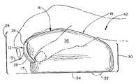
- FIG. 1is an isometric view of one embodiment of the present invention, viewed from its top and front.
- FIG. 2is a side elevational view of the embodiment of FIG. 1 with a user's hand shown in phantom.
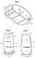
- FIG. 3is an isometric view of the embodiment of FIG. 1 , viewed from its bottom and rear.
- FIG. 4is a bottom elevational view of the embodiment of FIG. 1 .
- FIG. 5is a top elevational view of the embodiment of FIG. 1 .
- FIG. 6is a front elevational view of the embodiment of FIG. 1 .
- FIG. 7is a rear elevational view of the embodiment of FIG. 1 .
- FIG. 1depicts the ergonomic mouse 10 of one embodiment of the present invention.
- the exterior of the mouse 10is a housing 11 with a generally curved top surface 14 , a front face 24 , and a rear face 30 .
- the front face 24 of the mouse 10 as shownhas two signaling devices 12 , one, two, or more signaling devices 12 are acceptable.
- the signaling devices 12are depicted as buttons actuated by depressing them into the housing 11 , any pressure- or contact-sensitive signaling device 12 may be utilized.
- FIG. 1also depicts the top surface 14 of the mouse 10 .
- the top surface 14may have a gently curved upper top surface 16 and a gently curved lower top surface 18 that are joined and positioned to fit comfortably into the user's hand.
- the top surface 14may have an apex 20 at the joining line between the upper top surface 16 and lower top surface 18 that is positioned to fit under the user's knuckles.
- FIG. 1also depicts left side 38 with a thumb groove 22 that is positioned to accommodate a right-handed user's thumb in a relaxed state.
- each signaling device 12may be located on the mouse's front face 24 .
- the front face 24 of the mouse 10is curved, but any suitable shape will work.
- the user's fingerswill curl around the front face 24 of the mouse 10 .
- the actuation surface of signaling device 12may have an upper segment 26 , a lower segment 28 , or (as shown) both.
- the userneed only slightly close the finger(s) of his or her hand in a natural manner, thus exerting against the signaling device 12 fingertip pressure that is directed upward, rearward, or both (see arrow 15 ).
- the upper segment 26is positioned so that, to actuate the signaling device 12 , the user exerts pressure on the upper segment 26 that is directed generally toward the rear face 30 of the mouse 10 .
- the signaling device 12may be actuated by moving the fingertips in a direction that is generally parallel to the work surface 17 on which the mouse 10 moves.
- the upper segment 26is generally vertically oriented, the upper segment 26 may be configured so that an imaginary plane tangent to the upper segment 26 may be oriented so as to have an angle of plus or minus 45° relative to a plane that is perpendicular to the bottom surface 34 of the mouse 10 .
- the lower segment 28is positioned so that, to actuate the signaling device 12 , the user exerts pressure on the lower segment 28 that is directed both rearward and somewhat upward, toward the top surface 14 of the mouse 10 .
- the lower segment 28thus slopes downwardly and toward the rear face 30 of the mouse 10 .
- the lower segment 28may be oriented to have a wide range of angular orientations with respect to the bottom surface 34 of the mouse 10 . Accordingly, for any point on the lower segment 28 , a vector that extends in a direction normal to an imaginary plane that is tangent to the lower segment 28 at that point will extend toward the work surface 17 .
- the lower segment 28thus is oriented so that such a vector has a vertical component that is directed toward the work surface 17 , and a horizontal component that may be directed either toward or away from the rear face 30 of the mouse 10 .
- the lower segment 28also may be positioned generally parallel to the bottom surface 34 of the mouse 10 .
- the distance between the front face 24 and the rear face 30 of the mouse 10is selected such that the mouse 10 is easily enclosed in a relaxed hand; that is, the user's fingertips are in contact with the signaling device(s) 12 ; the fingers, knuckles, and palm curve over upper top surface 16 and lower top surface 18 ; and the fleshy lower part of the palm rests against the rear face 30 .
- the movement sensoris spaced from the front face 24 of the mouse 10 by a distance that is generally equal to that between a hand's wrist joint and fingertips when the hand is in a relaxed, nonextended state. If desired, the mouse 10 may be made in different sizes to provide this fit for different size hands. As depicted in FIG.
- the user's wrist joint pivot point 42is located between the movement sensor 32 and the rear face 30 of the mouse 10 .
- Any mouse, even if shorter or longer than the user's hand, that permits the movement sensor 32 to be positioned so that the movement sensor 32 is closer to the user's wrist joint than it is to the user's knucklesaids the goal of encouraging arm motion rather than wrist flexing.
- the movement sensor 32may be under or only slightly displaced from the user's wrist joint.
- the embodiments of the present inventionare intended to accommodate any size hand, adult or child.
- the embodiment depicted hereinis intended to accommodate North American adult users within a defined range of hand size that is bounded on the smaller end by a 5th percentile female hand and on the larger end by a 95th percentile male hand.
- the embodiment depicted hereinis intended to accommodate 95 percent of adult mouse users.
- Other userseasily may be accommodated with larger or smaller embodiments.
- the two segmentswhen both are used, may be located in any suitable arrangement, with the upper segment 26 located below the lower-segment 28 or with the “upper” and “lower” segments 26 , 28 positioned side-by-side.
- the mousewill substantially accommodate the user's fingers in their relaxed and nonextended state, and the user will be able to actuate the signaling device 12 simply by closing his or her hand in a natural manner, thus exerting pressure on the signaling device 12 as described above.
- the signaling device 12may be sized to accommodate one or more fingers.
- embodiments of the present inventiondecrease fatigue in the user's hand, thereby helping to avoid or minimize repetitive stress injuries, make the mouse more comfortable to use, and facilitate user productivity.
- the location the signaling device(s) 12may ensure that the user's hand will be positioned properly on top of the mouse 10 , i.e., with the user's wrist located substantially over the rear face 30 of the mouse 10 .
- FIG. 3depicts the bottom of the mouse 10 . From this angle it can be seen that the movement sensor 32 of the mouse 10 is located in the bottom surface 34 of the mouse 10 , substantially equidistant from the sides 36 , 38 . In particular, it is located adjacent the rear face 30 of the mouse 10 . In the embodiment depicted, the movement sensor 32 will be located closer to the rear face 30 than to the front face 24 of the mouse 10 , i.e., in the rear half (50 percent) of the mouse 10 , as measured by the distance between front face 34 and rear face 30 . Preferably, the movement sensor 32 will be located in the rear third (33 percent) of the mouse 10 , or alternatively in the rear fourth (25 percent) or fifth (20 percent) of the mouse.
- the movement sensor 32is a standard mouse ball, mounted for free revolution in contact with internal rollers.
- any suitable movement sensor 32will work, and the specific type of movement sensor 32 employed is not important.
- the movement sensor 32may detect movement in either two or three dimensions, depending on its structure and the software being used.
- the placement of the movement sensor 32 toward or adjacent to the rear of the mouse 10is intended to reduce cursor control from a user's wrist-flexing movement, a principal cause of repetitive stress injuries; it also encourages cursor control from movement of the user's arm.
- This placementtogether with selecting a suitable distance between the front and rear faces 24 , 30 of the mouse 10 , causes the movement sensor 32 to be positioned so that it is closer to the user's wrist joint than the user's knuckles, and preferably adjacent the user's wrist joint.
- the positioning of the movement sensor 32 near the wrist jointthus encourages more ergonomically proper techniques, decreases user fatigue and susceptibility to repetitive stress injuries, and facilitates user comfort and productivity.
- the movement sensor 32may be located equidistant from the sides 36 , 38 of the mouse.
- FIG. 4also shows that the lower segment 28 of the signaling device 12 extends toward the bottom surface 34 and rear face 30 of the mouse 10 .
- FIGS. 2 and 5also show that the thumb groove 22 is an indentation both horizontally and vertically, so that it resembles an hour-glass.
- the mouse 10is suitable for both left- and right-handed users. Nevertheless, it is contemplated that asymmetrical modifications to the housing 11 of the mouse 10 may be made so that the mouse 10 is more specifically tailored to a left- or a right-handed user. It further is contemplated that the mouse 10 may be provided in different sizes for different hand sizes.
- FIG. 6shows the thumb grooves 22 viewed by looking at the front face 24 of the mouse 10 .
- the mouse 10may be physically connected to a computer by a cable 40 (shown in phantom) that extends from the front face 24 of the mouse 10 , or a cable that extends from any location on the mouse 10 .
- An infrared, radio frequency, or other wireless communication protocolalso may be used.
- FIG. 7depicts the rear face 30 of the mouse 10 , and provides another view of the thumb grooves 22 .
- the usergrasps the mouse 10 with his or her hand resting on the top surface 14 of the mouse 10 , with the palm on the lower top surface 18 and the fingers on the upper top surface 16 .
- the user's knuckleswill be positioned generally above the apex 20 .
- the ends of the user's fingerswill extend around to the front face 24 to reach the signaling devices 12 in a natural, nonextended state. This positioning also encourages the user to locate his or her wrist generally above the rear face 30 of the mouse 10 , and thus generally adjacent to and over the movement sensor 32 .
- the user's thumbcomfortably will fit into a thumb groove 22 .
- the userTo move the mouse 10 easily, the user must move his or her forearm, because wrist movement alone will provide only a small amount of cursor control. Wrist fatigue thus is reduced, and the advantages discussed above are provided.
- the userTo actuate the signaling devices 12 , the user need only slightly pull his or her fingers inward, pressing against an upper segment 26 of the signaling device 12 , or exerting upward and rearward pressure against a lower segment 28 of the signaling device 12 , or both. This essentially natural, minimal movement reduces user fatigue, and also provides the advantages discussed above.
Landscapes
- Engineering & Computer Science (AREA)
- General Engineering & Computer Science (AREA)
- Theoretical Computer Science (AREA)
- Human Computer Interaction (AREA)
- Physics & Mathematics (AREA)
- General Physics & Mathematics (AREA)
- Position Input By Displaying (AREA)
Abstract
Description
Claims (20)
Priority Applications (1)
| Application Number | Priority Date | Filing Date | Title |
|---|---|---|---|
| US11/336,173US7701443B2 (en) | 1997-11-10 | 2006-01-20 | Ergonomic computer mouse |
Applications Claiming Priority (2)
| Application Number | Priority Date | Filing Date | Title |
|---|---|---|---|
| US08/966,761US7006075B1 (en) | 1997-11-10 | 1997-11-10 | Ergonomic computer mouse |
| US11/336,173US7701443B2 (en) | 1997-11-10 | 2006-01-20 | Ergonomic computer mouse |
Related Parent Applications (2)
| Application Number | Title | Priority Date | Filing Date |
|---|---|---|---|
| US08/966,761ContinuationUS7006075B1 (en) | 1997-11-10 | 1997-11-10 | Ergonomic computer mouse |
| US08/996,761ContinuationUS5924097A (en) | 1997-12-23 | 1997-12-23 | Balanced input/output task management for use in multiprocessor transaction processing system |
Publications (2)
| Publication Number | Publication Date |
|---|---|
| US20060139331A1 US20060139331A1 (en) | 2006-06-29 |
| US7701443B2true US7701443B2 (en) | 2010-04-20 |
Family
ID=35922787
Family Applications (2)
| Application Number | Title | Priority Date | Filing Date |
|---|---|---|---|
| US08/966,761Expired - LifetimeUS7006075B1 (en) | 1997-11-10 | 1997-11-10 | Ergonomic computer mouse |
| US11/336,173Expired - Fee RelatedUS7701443B2 (en) | 1997-11-10 | 2006-01-20 | Ergonomic computer mouse |
Family Applications Before (1)
| Application Number | Title | Priority Date | Filing Date |
|---|---|---|---|
| US08/966,761Expired - LifetimeUS7006075B1 (en) | 1997-11-10 | 1997-11-10 | Ergonomic computer mouse |
Country Status (1)
| Country | Link |
|---|---|
| US (2) | US7006075B1 (en) |
Cited By (1)
| Publication number | Priority date | Publication date | Assignee | Title |
|---|---|---|---|---|
| US20080100573A1 (en)* | 2006-10-27 | 2008-05-01 | Jack Lo | Compact ergonomic computer mouse |
Families Citing this family (17)
| Publication number | Priority date | Publication date | Assignee | Title |
|---|---|---|---|---|
| US7510483B2 (en) | 2004-07-09 | 2009-03-31 | William S. Tremulis | Golf club grip |
| US20060227108A1 (en)* | 2005-03-31 | 2006-10-12 | Ikey, Ltd. | Computer mouse for harsh environments and method of fabrication |
| US7294799B2 (en)* | 2005-10-13 | 2007-11-13 | Ikey, Ltd. | Smooth keyboard with low key height |
| DE602006018510D1 (en)* | 2005-10-21 | 2011-01-05 | Stryker Corp | SYSTEM AND METHOD FOR RECHARGING A HARSH ENVIRONMENT EXPOSED BATTERY |
| USD574826S1 (en) | 2005-12-22 | 2008-08-12 | Ikey, Ltd. | Industrial computer keyboard |
| US20070243734A1 (en)* | 2006-04-13 | 2007-10-18 | Yuan-Jung Chang | Mouse with direction-adjustable connecting wire |
| US8022930B2 (en)* | 2006-06-01 | 2011-09-20 | Microsoft Corporation | Ergonomic input device |
| US20070291003A1 (en)* | 2006-06-14 | 2007-12-20 | The Hesed Consortia, Llc | Lap positioned computer cursor control /input device |
| US20110234495A1 (en)* | 2007-07-26 | 2011-09-29 | Hoe Chan | Programmable touch sensitive controller |
| US7948474B2 (en)* | 2007-11-29 | 2011-05-24 | Microsoft Corporation | Ergonomic computer mouse |
| USD599349S1 (en) | 2008-07-14 | 2009-09-01 | Ikey, Ltd. | Keyboard |
| US8314772B1 (en) | 2009-08-28 | 2012-11-20 | Coe Stanley S | Computer mouse |
| US10496188B2 (en)* | 2013-08-26 | 2019-12-03 | Logitech Europe S.A. | Zonal input device |
| KR101826552B1 (en)* | 2014-11-28 | 2018-02-07 | 현대자동차 주식회사 | Intecrated controller system for vehicle |
| US11064950B2 (en) | 2017-10-27 | 2021-07-20 | Bluue Co. | Hand-held heart monitoring device |
| US10599233B1 (en)* | 2019-03-01 | 2020-03-24 | Alfaisal University | Computer mouse device with modified design and functionality |
| WO2021191658A1 (en) | 2020-03-24 | 2021-09-30 | Alfaisal University | Computer mouse |
Citations (38)
| Publication number | Priority date | Publication date | Assignee | Title |
|---|---|---|---|---|
| US3892963A (en) | 1973-12-20 | 1975-07-01 | Xerox Corp | Transducer for a display-oriented pointing device |
| USD281164S (en) | 1983-04-25 | 1985-10-29 | Wico Corporation | Mouse |
| US4613853A (en) | 1983-07-14 | 1986-09-23 | Alps Electric Co., Ltd. | X-Y Input device |
| USD288569S (en) | 1983-09-28 | 1987-03-03 | Alps Electric Co., Ltd. | X-Y input device |
| USRE32632E (en) | 1982-07-19 | 1988-03-29 | Apple Computer, Inc. | Display system |
| US4806917A (en) | 1985-09-05 | 1989-02-21 | Alps Electric Co., Ltd. | X-Y direction input device |
| USD300324S (en) | 1985-10-30 | 1989-03-21 | Digital Equipment Corporation | Cursor control for computer display |
| US4847484A (en) | 1987-04-23 | 1989-07-11 | Alps Electric Co., Ltd. | Portable image sanner having movement detection means and a window for transmitting light to the viewer |
| US4917516A (en) | 1987-02-18 | 1990-04-17 | Retter Dale J | Combination computer keyboard and mouse data entry system |
| US5001467A (en) | 1989-12-28 | 1991-03-19 | Chien Fong K | Structure of optical mouse |
| US5095303A (en) | 1990-03-27 | 1992-03-10 | Apple Computer, Inc. | Six degree of freedom graphic object controller |
| US5122786A (en) | 1990-06-27 | 1992-06-16 | Freeman Rader | Ergonomic keypads for desktop and armrest applications |
| US5157381A (en) | 1990-04-23 | 1992-10-20 | Cheng San Yih | Computer mouse |
| USD335875S (en) | 1990-06-18 | 1993-05-25 | Jimmy Chen | Computer mouse |
| US5260696A (en) | 1991-02-19 | 1993-11-09 | Maynard Jr Stuart T | Multiple signaling mouse with faceted surfaces |
| US5340067A (en) | 1992-03-27 | 1994-08-23 | Martin Teresa A | Hand and wrist support for computer mouse |
| US5349371A (en) | 1991-06-04 | 1994-09-20 | Fong Kwang Chien | Electro-optical mouse with means to separately detect the changes in contrast ratio in X and Y directions |
| US5355147A (en) | 1993-10-04 | 1994-10-11 | Donald Lear | Ergonomic computer mouse |
| US5367631A (en) | 1992-04-14 | 1994-11-22 | Apple Computer, Inc. | Cursor control device with programmable preset cursor positions |
| USD354746S (en) | 1993-03-01 | 1995-01-24 | Xecos AG International | Computer mouse |
| US5414445A (en) | 1992-10-07 | 1995-05-09 | Microsoft Corporation | Ergonomic pointing device |
| USD359277S (en) | 1993-05-12 | 1995-06-13 | Sun Microsystems, Inc. | Computer mouse |
| US5538431A (en) | 1995-03-24 | 1996-07-23 | Dempster; Gregory | Typing & mouse manipulation technique and instruction method |
| USD373999S (en) | 1993-10-29 | 1996-09-24 | Kai Staats | Combined ergonomic split keyboard and mouse set |
| US5563629A (en) | 1993-09-24 | 1996-10-08 | Sintecna S.R.L. | Device for pointing the cursor on the screen of interactive systems |
| US5570112A (en) | 1994-10-12 | 1996-10-29 | Robinson; Calvin H. A. | Ergonomic computer mouse |
| US5576733A (en) | 1994-05-25 | 1996-11-19 | Lo; Jack | Ergonomic computer mouse |
| US5581277A (en) | 1995-03-06 | 1996-12-03 | Tajiri; Akira | Anti-carpal tunnel device (ACTD) for computer operators |
| US5626427A (en) | 1989-04-14 | 1997-05-06 | Keyboard Advancements, Inc. | Keyboard with transverse thumb activated cursor control |
| US5648798A (en) | 1995-02-13 | 1997-07-15 | Hamling; Daniel T. | Universal ergonomic computer mouse/trackball |
| US5726683A (en) | 1995-08-09 | 1998-03-10 | Midas Mouse International Pty. | Ergonomic computer mouse |
| USD397330S (en) | 1997-09-18 | 1998-08-25 | Lister-Myers Elaine M | Computer mouse |
| US5841425A (en) | 1996-07-31 | 1998-11-24 | International Business Machines Corporation | Ambidextrous computer input device |
| US5894302A (en) | 1995-08-28 | 1999-04-13 | Contour Design, Inc. | Ergonomic housing for a computer mouse |
| US5982352A (en) | 1992-09-18 | 1999-11-09 | Pryor; Timothy R. | Method for providing human input to a computer |
| US6005553A (en)* | 1995-08-09 | 1999-12-21 | Midas Mouse International Pty. Ltd. | Ergonomic computer mouse |
| US6078549A (en) | 1995-05-18 | 2000-06-20 | Rmp, Inc. | Rest pattern timing system |
| US6362811B1 (en)* | 1996-02-20 | 2002-03-26 | George Neil Edwards | Ergonomic computer mouse |
Family Cites Families (1)
| Publication number | Priority date | Publication date | Assignee | Title |
|---|---|---|---|---|
| US6781573B1 (en)* | 2000-04-25 | 2004-08-24 | Intel Corporation | Ergonomic mouse |
- 1997
- 1997-11-10USUS08/966,761patent/US7006075B1/ennot_activeExpired - Lifetime
- 2006
- 2006-01-20USUS11/336,173patent/US7701443B2/ennot_activeExpired - Fee Related
Patent Citations (39)
| Publication number | Priority date | Publication date | Assignee | Title |
|---|---|---|---|---|
| US3892963A (en) | 1973-12-20 | 1975-07-01 | Xerox Corp | Transducer for a display-oriented pointing device |
| USRE32632E (en) | 1982-07-19 | 1988-03-29 | Apple Computer, Inc. | Display system |
| USD281164S (en) | 1983-04-25 | 1985-10-29 | Wico Corporation | Mouse |
| US4613853A (en) | 1983-07-14 | 1986-09-23 | Alps Electric Co., Ltd. | X-Y Input device |
| USD288569S (en) | 1983-09-28 | 1987-03-03 | Alps Electric Co., Ltd. | X-Y input device |
| US4806917A (en) | 1985-09-05 | 1989-02-21 | Alps Electric Co., Ltd. | X-Y direction input device |
| USD300324S (en) | 1985-10-30 | 1989-03-21 | Digital Equipment Corporation | Cursor control for computer display |
| US4917516A (en) | 1987-02-18 | 1990-04-17 | Retter Dale J | Combination computer keyboard and mouse data entry system |
| US4847484A (en) | 1987-04-23 | 1989-07-11 | Alps Electric Co., Ltd. | Portable image sanner having movement detection means and a window for transmitting light to the viewer |
| US5626427A (en) | 1989-04-14 | 1997-05-06 | Keyboard Advancements, Inc. | Keyboard with transverse thumb activated cursor control |
| US5001467A (en) | 1989-12-28 | 1991-03-19 | Chien Fong K | Structure of optical mouse |
| US5095303A (en) | 1990-03-27 | 1992-03-10 | Apple Computer, Inc. | Six degree of freedom graphic object controller |
| US5157381A (en) | 1990-04-23 | 1992-10-20 | Cheng San Yih | Computer mouse |
| USD335875S (en) | 1990-06-18 | 1993-05-25 | Jimmy Chen | Computer mouse |
| US5122786A (en) | 1990-06-27 | 1992-06-16 | Freeman Rader | Ergonomic keypads for desktop and armrest applications |
| US5260696A (en) | 1991-02-19 | 1993-11-09 | Maynard Jr Stuart T | Multiple signaling mouse with faceted surfaces |
| US5349371A (en) | 1991-06-04 | 1994-09-20 | Fong Kwang Chien | Electro-optical mouse with means to separately detect the changes in contrast ratio in X and Y directions |
| US5340067A (en) | 1992-03-27 | 1994-08-23 | Martin Teresa A | Hand and wrist support for computer mouse |
| US5367631A (en) | 1992-04-14 | 1994-11-22 | Apple Computer, Inc. | Cursor control device with programmable preset cursor positions |
| US5982352A (en) | 1992-09-18 | 1999-11-09 | Pryor; Timothy R. | Method for providing human input to a computer |
| US5414445A (en) | 1992-10-07 | 1995-05-09 | Microsoft Corporation | Ergonomic pointing device |
| USD354746S (en) | 1993-03-01 | 1995-01-24 | Xecos AG International | Computer mouse |
| USD359277S (en) | 1993-05-12 | 1995-06-13 | Sun Microsystems, Inc. | Computer mouse |
| US5563629A (en) | 1993-09-24 | 1996-10-08 | Sintecna S.R.L. | Device for pointing the cursor on the screen of interactive systems |
| US5355147A (en) | 1993-10-04 | 1994-10-11 | Donald Lear | Ergonomic computer mouse |
| USD373999S (en) | 1993-10-29 | 1996-09-24 | Kai Staats | Combined ergonomic split keyboard and mouse set |
| US5576733A (en) | 1994-05-25 | 1996-11-19 | Lo; Jack | Ergonomic computer mouse |
| US5570112A (en) | 1994-10-12 | 1996-10-29 | Robinson; Calvin H. A. | Ergonomic computer mouse |
| US5648798A (en) | 1995-02-13 | 1997-07-15 | Hamling; Daniel T. | Universal ergonomic computer mouse/trackball |
| US5581277A (en) | 1995-03-06 | 1996-12-03 | Tajiri; Akira | Anti-carpal tunnel device (ACTD) for computer operators |
| US5538431A (en) | 1995-03-24 | 1996-07-23 | Dempster; Gregory | Typing & mouse manipulation technique and instruction method |
| US6078549A (en) | 1995-05-18 | 2000-06-20 | Rmp, Inc. | Rest pattern timing system |
| US5726683A (en) | 1995-08-09 | 1998-03-10 | Midas Mouse International Pty. | Ergonomic computer mouse |
| US6005553A (en)* | 1995-08-09 | 1999-12-21 | Midas Mouse International Pty. Ltd. | Ergonomic computer mouse |
| US6124846A (en)* | 1995-08-09 | 2000-09-26 | Midas Mouse International Pty. Ltd. | Pointing device with ergonomic features |
| US5894302A (en) | 1995-08-28 | 1999-04-13 | Contour Design, Inc. | Ergonomic housing for a computer mouse |
| US6362811B1 (en)* | 1996-02-20 | 2002-03-26 | George Neil Edwards | Ergonomic computer mouse |
| US5841425A (en) | 1996-07-31 | 1998-11-24 | International Business Machines Corporation | Ambidextrous computer input device |
| USD397330S (en) | 1997-09-18 | 1998-08-25 | Lister-Myers Elaine M | Computer mouse |
Cited By (1)
| Publication number | Priority date | Publication date | Assignee | Title |
|---|---|---|---|---|
| US20080100573A1 (en)* | 2006-10-27 | 2008-05-01 | Jack Lo | Compact ergonomic computer mouse |
Also Published As
| Publication number | Publication date |
|---|---|
| US20060139331A1 (en) | 2006-06-29 |
| US7006075B1 (en) | 2006-02-28 |
Similar Documents
| Publication | Publication Date | Title |
|---|---|---|
| US7701443B2 (en) | Ergonomic computer mouse | |
| US6545667B1 (en) | Apparatus for a convenient and comfortable cursor control device | |
| US5576733A (en) | Ergonomic computer mouse | |
| US5648798A (en) | Universal ergonomic computer mouse/trackball | |
| US6441805B1 (en) | Ergonomic computer mouse | |
| US6064371A (en) | PC mouse incorporating adjustability | |
| US20020171625A1 (en) | Pistol-grip trackball mouse | |
| EP1374218A1 (en) | Computer mouse | |
| EP1159706A2 (en) | Safe and handy pointing device | |
| US6147673A (en) | Computer input device and keyboard | |
| US6104383A (en) | Thumb-actuated computer pointing-input device | |
| US6954198B2 (en) | Ergonomically shaped computer pointing device | |
| US7705827B1 (en) | Ergonomic computer mouse | |
| US6549189B1 (en) | Method for operating a computer input device and keyboard | |
| EP1063609A3 (en) | Ergonomic computer mouse | |
| US20090289896A1 (en) | Input arrangement for electronic devices | |
| US6680728B1 (en) | Cursor control device for convenient and ergonomic hand-held or work-surface use | |
| US6031523A (en) | Meta-rest improved PC mouse | |
| KR100479537B1 (en) | A computer input device and a computer mouse for a personal computer | |
| US20060007152A1 (en) | Computer finger mouse | |
| WO2000029933A1 (en) | Ergonomic computer mouse | |
| US20010006381A1 (en) | Finger-scale mouse casing structure | |
| KR200200914Y1 (en) | Mouse | |
| US20060176268A1 (en) | Device for inputting control signals to a peripheral unit and a combination including such a device | |
| JP2003256131A (en) | Mouse |
Legal Events
| Date | Code | Title | Description |
|---|---|---|---|
| STCF | Information on status: patent grant | Free format text:PATENTED CASE | |
| FEPP | Fee payment procedure | Free format text:PAYOR NUMBER ASSIGNED (ORIGINAL EVENT CODE: ASPN); ENTITY STATUS OF PATENT OWNER: LARGE ENTITY | |
| FPAY | Fee payment | Year of fee payment:4 | |
| AS | Assignment | Owner name:U.S. BANK NATIONAL ASSOCIATION, AS COLLATERAL AGENT, CALIFORNIA Free format text:SECURITY INTEREST;ASSIGNOR:MICRON TECHNOLOGY, INC.;REEL/FRAME:038669/0001 Effective date:20160426 Owner name:U.S. BANK NATIONAL ASSOCIATION, AS COLLATERAL AGEN Free format text:SECURITY INTEREST;ASSIGNOR:MICRON TECHNOLOGY, INC.;REEL/FRAME:038669/0001 Effective date:20160426 | |
| AS | Assignment | Owner name:MORGAN STANLEY SENIOR FUNDING, INC., AS COLLATERAL AGENT, MARYLAND Free format text:PATENT SECURITY AGREEMENT;ASSIGNOR:MICRON TECHNOLOGY, INC.;REEL/FRAME:038954/0001 Effective date:20160426 Owner name:MORGAN STANLEY SENIOR FUNDING, INC., AS COLLATERAL Free format text:PATENT SECURITY AGREEMENT;ASSIGNOR:MICRON TECHNOLOGY, INC.;REEL/FRAME:038954/0001 Effective date:20160426 | |
| AS | Assignment | Owner name:U.S. BANK NATIONAL ASSOCIATION, AS COLLATERAL AGENT, CALIFORNIA Free format text:CORRECTIVE ASSIGNMENT TO CORRECT THE REPLACE ERRONEOUSLY FILED PATENT #7358718 WITH THE CORRECT PATENT #7358178 PREVIOUSLY RECORDED ON REEL 038669 FRAME 0001. ASSIGNOR(S) HEREBY CONFIRMS THE SECURITY INTEREST;ASSIGNOR:MICRON TECHNOLOGY, INC.;REEL/FRAME:043079/0001 Effective date:20160426 Owner name:U.S. BANK NATIONAL ASSOCIATION, AS COLLATERAL AGEN Free format text:CORRECTIVE ASSIGNMENT TO CORRECT THE REPLACE ERRONEOUSLY FILED PATENT #7358718 WITH THE CORRECT PATENT #7358178 PREVIOUSLY RECORDED ON REEL 038669 FRAME 0001. ASSIGNOR(S) HEREBY CONFIRMS THE SECURITY INTEREST;ASSIGNOR:MICRON TECHNOLOGY, INC.;REEL/FRAME:043079/0001 Effective date:20160426 | |
| MAFP | Maintenance fee payment | Free format text:PAYMENT OF MAINTENANCE FEE, 8TH YEAR, LARGE ENTITY (ORIGINAL EVENT CODE: M1552) Year of fee payment:8 | |
| AS | Assignment | Owner name:MICRON TECHNOLOGY, INC., IDAHO Free format text:RELEASE BY SECURED PARTY;ASSIGNOR:U.S. BANK NATIONAL ASSOCIATION, AS COLLATERAL AGENT;REEL/FRAME:047243/0001 Effective date:20180629 | |
| AS | Assignment | Owner name:MICRON TECHNOLOGY, INC., IDAHO Free format text:RELEASE BY SECURED PARTY;ASSIGNOR:MORGAN STANLEY SENIOR FUNDING, INC., AS COLLATERAL AGENT;REEL/FRAME:050937/0001 Effective date:20190731 | |
| FEPP | Fee payment procedure | Free format text:MAINTENANCE FEE REMINDER MAILED (ORIGINAL EVENT CODE: REM.); ENTITY STATUS OF PATENT OWNER: LARGE ENTITY | |
| LAPS | Lapse for failure to pay maintenance fees | Free format text:PATENT EXPIRED FOR FAILURE TO PAY MAINTENANCE FEES (ORIGINAL EVENT CODE: EXP.); ENTITY STATUS OF PATENT OWNER: LARGE ENTITY | |
| STCH | Information on status: patent discontinuation | Free format text:PATENT EXPIRED DUE TO NONPAYMENT OF MAINTENANCE FEES UNDER 37 CFR 1.362 | |
| FP | Lapsed due to failure to pay maintenance fee | Effective date:20220420 |