US7699879B2 - Apparatus and method for providing dynamizable translations to orthopedic implants - Google Patents
Apparatus and method for providing dynamizable translations to orthopedic implantsDownload PDFInfo
- Publication number
- US7699879B2 US7699879B2US10/689,961US68996103AUS7699879B2US 7699879 B2US7699879 B2US 7699879B2US 68996103 AUS68996103 AUS 68996103AUS 7699879 B2US7699879 B2US 7699879B2
- Authority
- US
- United States
- Prior art keywords
- opening
- restricting component
- bone
- rod
- restricting
- Prior art date
- Legal status (The legal status is an assumption and is not a legal conclusion. Google has not performed a legal analysis and makes no representation as to the accuracy of the status listed.)
- Expired - Fee Related, expires
Links
Images


Classifications
- A—HUMAN NECESSITIES
- A61—MEDICAL OR VETERINARY SCIENCE; HYGIENE
- A61B—DIAGNOSIS; SURGERY; IDENTIFICATION
- A61B17/00—Surgical instruments, devices or methods
- A61B17/56—Surgical instruments or methods for treatment of bones or joints; Devices specially adapted therefor
- A61B17/58—Surgical instruments or methods for treatment of bones or joints; Devices specially adapted therefor for osteosynthesis, e.g. bone plates, screws or setting implements
- A61B17/68—Internal fixation devices, including fasteners and spinal fixators, even if a part thereof projects from the skin
- A61B17/70—Spinal positioners or stabilisers, e.g. stabilisers comprising fluid filler in an implant
- A61B17/7001—Screws or hooks combined with longitudinal elements which do not contact vertebrae
- A61B17/7032—Screws or hooks with U-shaped head or back through which longitudinal rods pass
- A—HUMAN NECESSITIES
- A61—MEDICAL OR VETERINARY SCIENCE; HYGIENE
- A61B—DIAGNOSIS; SURGERY; IDENTIFICATION
- A61B17/00—Surgical instruments, devices or methods
- A61B17/56—Surgical instruments or methods for treatment of bones or joints; Devices specially adapted therefor
- A61B17/58—Surgical instruments or methods for treatment of bones or joints; Devices specially adapted therefor for osteosynthesis, e.g. bone plates, screws or setting implements
- A61B17/68—Internal fixation devices, including fasteners and spinal fixators, even if a part thereof projects from the skin
- A61B17/70—Spinal positioners or stabilisers, e.g. stabilisers comprising fluid filler in an implant
- A61B17/7001—Screws or hooks combined with longitudinal elements which do not contact vertebrae
- A61B17/7002—Longitudinal elements, e.g. rods
- A61B17/7004—Longitudinal elements, e.g. rods with a cross-section which varies along its length
- A61B17/7007—Parts of the longitudinal elements, e.g. their ends, being specially adapted to fit around the screw or hook heads
- A—HUMAN NECESSITIES
- A61—MEDICAL OR VETERINARY SCIENCE; HYGIENE
- A61B—DIAGNOSIS; SURGERY; IDENTIFICATION
- A61B17/00—Surgical instruments, devices or methods
- A61B17/56—Surgical instruments or methods for treatment of bones or joints; Devices specially adapted therefor
- A61B17/58—Surgical instruments or methods for treatment of bones or joints; Devices specially adapted therefor for osteosynthesis, e.g. bone plates, screws or setting implements
- A61B17/68—Internal fixation devices, including fasteners and spinal fixators, even if a part thereof projects from the skin
- A61B17/80—Cortical plates, i.e. bone plates; Instruments for holding or positioning cortical plates, or for compressing bones attached to cortical plates
- A61B17/8033—Cortical plates, i.e. bone plates; Instruments for holding or positioning cortical plates, or for compressing bones attached to cortical plates having indirect contact with screw heads, or having contact with screw heads maintained with the aid of additional components, e.g. nuts, wedges or head covers
- A61B17/8042—Cortical plates, i.e. bone plates; Instruments for holding or positioning cortical plates, or for compressing bones attached to cortical plates having indirect contact with screw heads, or having contact with screw heads maintained with the aid of additional components, e.g. nuts, wedges or head covers the additional component being a cover over the screw head
- A—HUMAN NECESSITIES
- A61—MEDICAL OR VETERINARY SCIENCE; HYGIENE
- A61B—DIAGNOSIS; SURGERY; IDENTIFICATION
- A61B17/00—Surgical instruments, devices or methods
- A61B17/56—Surgical instruments or methods for treatment of bones or joints; Devices specially adapted therefor
- A61B17/58—Surgical instruments or methods for treatment of bones or joints; Devices specially adapted therefor for osteosynthesis, e.g. bone plates, screws or setting implements
- A61B17/60—Surgical instruments or methods for treatment of bones or joints; Devices specially adapted therefor for osteosynthesis, e.g. bone plates, screws or setting implements for external osteosynthesis, e.g. distractors, contractors
- A61B17/64—Devices extending alongside the bones to be positioned
- A61B17/6491—Devices extending alongside the bones to be positioned allowing small-scale motion of bone ends
- A—HUMAN NECESSITIES
- A61—MEDICAL OR VETERINARY SCIENCE; HYGIENE
- A61B—DIAGNOSIS; SURGERY; IDENTIFICATION
- A61B17/00—Surgical instruments, devices or methods
- A61B17/56—Surgical instruments or methods for treatment of bones or joints; Devices specially adapted therefor
- A61B17/58—Surgical instruments or methods for treatment of bones or joints; Devices specially adapted therefor for osteosynthesis, e.g. bone plates, screws or setting implements
- A61B17/68—Internal fixation devices, including fasteners and spinal fixators, even if a part thereof projects from the skin
- A61B17/686—Plugs, i.e. elements forming interface between bone hole and implant or fastener, e.g. screw
- A—HUMAN NECESSITIES
- A61—MEDICAL OR VETERINARY SCIENCE; HYGIENE
- A61B—DIAGNOSIS; SURGERY; IDENTIFICATION
- A61B17/00—Surgical instruments, devices or methods
- A61B17/56—Surgical instruments or methods for treatment of bones or joints; Devices specially adapted therefor
- A61B17/58—Surgical instruments or methods for treatment of bones or joints; Devices specially adapted therefor for osteosynthesis, e.g. bone plates, screws or setting implements
- A61B17/68—Internal fixation devices, including fasteners and spinal fixators, even if a part thereof projects from the skin
- A61B17/70—Spinal positioners or stabilisers, e.g. stabilisers comprising fluid filler in an implant
- A61B17/7059—Cortical plates
- A—HUMAN NECESSITIES
- A61—MEDICAL OR VETERINARY SCIENCE; HYGIENE
- A61B—DIAGNOSIS; SURGERY; IDENTIFICATION
- A61B17/00—Surgical instruments, devices or methods
- A61B17/56—Surgical instruments or methods for treatment of bones or joints; Devices specially adapted therefor
- A61B17/58—Surgical instruments or methods for treatment of bones or joints; Devices specially adapted therefor for osteosynthesis, e.g. bone plates, screws or setting implements
- A61B17/68—Internal fixation devices, including fasteners and spinal fixators, even if a part thereof projects from the skin
- A61B17/80—Cortical plates, i.e. bone plates; Instruments for holding or positioning cortical plates, or for compressing bones attached to cortical plates
- A61B17/8004—Cortical plates, i.e. bone plates; Instruments for holding or positioning cortical plates, or for compressing bones attached to cortical plates with means for distracting or compressing the bone or bones
- A—HUMAN NECESSITIES
- A61—MEDICAL OR VETERINARY SCIENCE; HYGIENE
- A61B—DIAGNOSIS; SURGERY; IDENTIFICATION
- A61B17/00—Surgical instruments, devices or methods
- A61B2017/00004—(bio)absorbable, (bio)resorbable or resorptive
- Y—GENERAL TAGGING OF NEW TECHNOLOGICAL DEVELOPMENTS; GENERAL TAGGING OF CROSS-SECTIONAL TECHNOLOGIES SPANNING OVER SEVERAL SECTIONS OF THE IPC; TECHNICAL SUBJECTS COVERED BY FORMER USPC CROSS-REFERENCE ART COLLECTIONS [XRACs] AND DIGESTS
- Y10—TECHNICAL SUBJECTS COVERED BY FORMER USPC
- Y10S—TECHNICAL SUBJECTS COVERED BY FORMER USPC CROSS-REFERENCE ART COLLECTIONS [XRACs] AND DIGESTS
- Y10S606/00—Surgery
- Y10S606/907—Composed of particular material or coated
- Y10S606/908—Bioabsorbable material
Definitions
- the present inventionrelates generally to orthopedic devices for promoting bone fusion and methods for treating orthopedic defects using the orthopedic devices.
- the spineis composed of both rigid and flexible elements which form a complex structure that can readily accommodate a wide range of motions and adjust to a wide range of loads.
- the spineis also vulnerable to disease, injury, and congenital deficiencies, all of which can cause defects to the spine and, in particular, to the vertebral body and intervertebral discs.
- Spinal disease, injury, and deformitymay have a disastrous impact on patient well being, ranging from acute pain to chronic debilitating pain and, in the most severe cases, partial or complete paralysis.
- spinal defectsSome of the most common pathologies of spinal defects include fractured, diseased, or decayed vertebral bodies; torn or stretched ligaments; and damaged or diseased intervertebral discs.
- Common treatments for damaged, diseased, or defective vertebraeinclude joining or fusing fractured bone segments or portions together to stabilize the affected parts and removing the affected vertebrae, either in part or in whole.
- the damaged discis excised, the adjacent vertebrae are mechanically joined together, and oftentimes bone is grafted into the region, particularly in the disc space between the two vertebrae, to promote fusion of the adjacent vertebrae.
- the vertebraecan be mechanically joined using a prosthetic device such as a bone plate that is attached to the adjacent vertebrae with bone screws.
- the bone plateeliminates disparate motion between the two bone portions to allow arthrodesis.
- torn and/or structural ligamentscan be treated by initially securing/immobilizing the ligaments. This can be accomplished using internal and/or external prosthetic devices to augment or replace the stability lost as a result of the damaged ligaments. Further, the treated ligaments can be susceptible to repeated injury. Consequently, it may be desirable to augment the treated ligament by implanting a prosthesis or device that allows limited movement of the affected ligaments, i.e., stretching and rotation of the ligaments. Current treatment methods do not allow for an implanted device to initially secure/immobilize the ligaments and then allow limited movement of the same without a subsequent surgical revisitation.
- the present inventionrelates to orthopedic devices and the manufacture and use thereof.
- Various aspects of the inventionare novel, nonobvious, and provide various advantages. While the actual nature of the invention covered herein can only be determined with reference to the claims appended hereto, certain forms and features, which are characteristic of the preferred embodiments disclosed herein, are described briefly as follows.
- the present inventionprovides an orthopedic device for securing two or more bone portions.
- the orthopedic devicecomprises: an elongate member including a receptacle therein and configured to be fixedly secured to two or more bone portions allowing translational, or rotational, or both translational and rotational movement of a first one of the bone portions relative to a second one of the bone portions; and a restricting component comprising a biodegradable material and disposed in the receptacle to inhibit the translational, the rotational, or both the translational and rotational movement of the first of the bone portions relative to the second of the bone portions.
- the orthopedic devicecan be used to treat a variety of bone defects including but not limited to: bone fractures, diseased bone tissue, spinal diseases, diseased/damaged vertebrae, torn or stretched ligaments, and the like.
- the deviceprevents stress shielding of new, developing bone tissue.
- the orthopedic device of the present inventioncan be configured for articulating joints.
- the devicecan allow a limited amount of movement, i.e. translation and/or rotation about the joint.
- the devices, with and without the biodegradable component,still provide a measure of support and/or restriction of the movement of bone portions attached to the device.
- the devices of the present inventionremain in place indefinitely.
- the present inventionprovides a device for securing bone portions.
- the devicecan comprise: a body member comprising a first arm and an opposite second arm defining a receptacle therebetween; an elongate rod disposed within the receptacle; a restricting component comprising a biodegradable material and disposed within the receptacle; and a cap configured to engage the first and second arms and secure the rod and the bioabsorbable restricting component in the receptacle.
- the present inventionprovides a method for treating a bone defect.
- the methodcomprises: providing an orthopedic device that includes an elongate member having at least one receptacle therein and a restricting component disposed within the at least one receptacle.
- the restricting componentis composed of a biodegradable material.
- the methodfurther includes securing the elongate member to a first bone portion with a first fastener and to a second bone portion with a second fastener to restrict translational or rotational movement or both the translational and rotational movement of the first bone portion relative to the second bone portion.
- the secured devicecan support and effectively immobilize the two bone portions relative to each other.
- the biodegradable materialcan degrade and, consequently, allow translational or rotational movement or both translational and rotational movement of the first bone portion relative to the second bone portion.
- the elongate memberremains secured to the first and second bone portions.
- the degradation of the biodegradable materialcan occur over time. This effectively transfers at least a portion of the support and/or biomechanical load from the elongate device to the new bone growth at the treatment site.
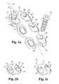
- FIG. 1 ais a perspective view of one embodiment of a bone fixation device comprising an elongate member in the form of a bone plate in accordance with the present invention.
- FIG. 1 bis a partial, perspective view of another embodiment of a bone fixation device similar to the device of FIG. 1 a , illustrating the restricting component symmetrically disposed in the receptacle in accordance with the present invention.
- FIG. 1 cis a partial, perspective view of still another embodiment of a bone fixation device similar to the device of FIG. 1 a , illustrating the restricting component asymmetrically disposed in the receptacle in accordance with the present invention.
- FIG. 2 ais a perspective view of one embodiment of an orthopedic device having a two-part telescoping elongate member in accordance with the present invention.
- FIG. 2 bis a perspective view of another embodiment of an orthopedic device having a two-part telescoping elongate member in accordance with the present invention.
- FIG. 2 cis a perspective view of still another embodiment of an orthopedic device having a two-part telescoping elongate member in accordance with the present invention.
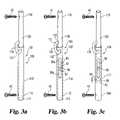
- FIG. 3 ais a perspective view of one embodiment of an orthopedic device having telescoping elongate members joined by a loop of material in accordance with the present invention.
- FIG. 3 bis a perspective view of another embodiment of an orthopedic device having telescoping elongate members joined by a loop of material in accordance with the present invention.
- FIG. 3 cis a perspective view of still another embodiment of an orthopedic device having telescoping elongate members joined by a loop of material in accordance with the present invention.
- FIG. 4 ais a perspective view of an embodiment of an orthopedic interconnection device comprising an anchoring body and an attached elongate member in accordance with the present invention.
- FIG. 4 bis a perspective view of another embodiment of an orthopedic interconnection device comprising an anchoring body and an attached elongate member in accordance with the present invention.
- FIG. 4 cis a perspective view of still another embodiment of an orthopedic device comprising an anchoring body and an attached elongate member in accordance with the present invention.
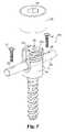
- FIG. 5is a perspective view of an embodiment of an orthopedic interconnection device comprising a pedicle screw, an attached elongate member, and a restricting component in accordance with the present invention.
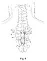
- FIG. 6is a plan view illustrating one embodiment of a method of treating the spine by attaching a bone plate having bioabsorbable restricting components in accordance with the present invention.
- the present inventionprovides an implantable orthopedic device or prosthesis to facilitate support and repair of defective bone structures and/or connective tissue.
- the defective bone structurescan be the result of damaged, traumatized, and/or diseased tissue.
- orthopedic deviceit is intended to include within its meaning a device that can be used to treat or repair defective, diseased, and/or damaged tissue of the muscular/skeletal system(s).
- the devices of the present inventioncan provide initial support and/or fixation of selected bone structures. After a selected period of time or under certain conditions, the amount and nature of the support/fixation can vary to facilitate a desirable treatment. For example, use of a device according to the present invention that allows the variable or dynamizable support develops new, strong bone tissue, thus minimizing the risk of pseudoarthrodesis.
- the biodegradable component of the present inventionprovides a restricting component for the inventive device.
- This restricting componentcan provide rigidity and support for both the implanted orthopedic fusion device and, consequently, the attached bone structures.
- the load supported by the bone fixation device and supported by the restricting componentcan vary. This allows the fixation device to become dynamizable, or change its support characteristics in vivo. This change in support characteristics can be particularly important for developing strong, new bone tissue at the bone defection or fusion site. This prevents stress shielding of the new bone ingrowth and minimizes the risk for the development of pseudoarthrodesis.
- the devices of the present inventionalso find advantageous use in the treatment of connecting tissue such as ligaments.
- the devicescan augment the connecting tissue.
- the devicecan allow limited movement, either translational or rotational or both translational and rotational, of the connecting tissue and/or attached bone structures as desired.
- the devicecan serve to limit or restrict the overall length or amount that the connecting tissue stretches. This restriction can vary depending upon the length of time or preselected conditions in forming and using the device.
- the following descriptionspecifically describes non-limiting, specific embodiments for use with the present invention.
- FIG. 1 ais a perspective view of one embodiment of an orthopedic device 10 comprising an elongate member 16 defining an elongate axis 52 .
- member 16comprises a bone plate 18 .
- Device 10can include one receptacle 24 or a plurality of receptacles 22 a , 22 b , 22 c . . . .
- Bone fastener 42can be inserted through receptacle 24 to secure elongate member 16 to one, two, or more bone portions.
- one or more of receptacles 22 a , 22 b , 22 c . . .are sized to have a larger opening than the outer diameter of the threads and/or shank of fastener 42 .
- member 16has limited freedom to move while secured to two or more bone portions.
- first end 17 of member 16When a first end 17 of member 16 is secured to a first bone portion, and a second end 19 is secured to a second bone portion, the two bone portions are free to move relative to each other and/or member 16 .
- receptacles 24 , 22 a , 22 b , 22 c . . .are provided as over-sized openings relative to the threads and/or shank of a bone fastener.
- receptacles 24 , 22 a , 22 b , 22 c . . .are provided as oblong openings. When provided as oblong openings, they can be oriented with the long dimension of the oval, either parallel with each other or at one or more angles with each other.
- Restricting component(s) 32 , 32 a , 32 b , 32 c . . .can be disposed in one or more of receptacles 24 , 22 a , 22 b , 22 c . . . . It will be understood that in alternative embodiments, each one of receptacles 24 , 22 a , 22 b , 22 c . . . need not include restricting component 32 , 32 a , 32 b , 32 c . . . respectively.
- Restricting component 32is operatively positioned to further inhibit or restrict the motion of bone portions (not shown) attached to device 10 .
- receptacle 24has a rim or edge 23 .
- Restricting component 32can be deposited in receptacle 24 between edge 23 and fastener 42 . In other embodiments, restricting component 32 completely surrounds fastener 42 . In this embodiment, restricting component 32 can initially fill up or cover over receptacle 24 . Fastener 42 can then be inserted through restricting component 32 and receptacle 24 . In other embodiments, restricting component 32 can be deposited in receptacle 24 and define an opening therethrough for receiving fastener 42 . In one preferred embodiment, restricting component 32 is operatively positioned within receptacle 24 such that restricting component 32 contacts only a portion of the edge 23 of receptacles 22 a , 22 b , 22 c.
- Restricting component 32is operatively positioned within receptacle 24 such that it further restricts the translational and/or rotational motion of attached bone portions.
- Receptacles 24 , 22 a , 22 b , 22 c . . .can be configured to allow or restrict movement of secured bone portions in only one direction, or two or more directions, as desired.
- receptacles 24 , 22 a , 22 b , 22 c . . .can be configured to allow either rotation or translation or both, as desired.
- Restricting component 32comprises a biodegradable material, discussed more fully below. In vivo, the biodegrading material degrades. In a preferred embodiment, after restricting component 32 has been eliminated, fastener 42 continues to secure elongate member 16 to attached bone portions. Elongate member 16 continues to provide at least some support to attached bone and to restrict at least some of the translational and/or rotational motion of attached bone portions.
- FIG. 1 bis a partial, perspective view of another embodiment of an orthopedic device 12 .
- Device 12is formed similarly to device 10 and, consequently, the same reference numbers are used to denote like components.
- Device 12comprises at least one receptacle 24 .
- a restricting component 34is symmetrically disposed in receptacle 24 .
- restricting component 34is placed in contact with the entire rim or edge 23 shown in dashed lines of receptacle 24 .
- Fastener 42extends through restricting component 34 and can be used to secure elongate member 16 to a portion of bone. When present, restricting component 34 is operatively positioned within device 12 so as to further restrict the motion of bone portions attached to device 12 .
- FIG. 1 cis a partial, perspective view of another preferred embodiment of an orthopedic device 14 .
- Device 14is formed similarly to device 10 and, consequently, the same reference numbers are used to denote like components.
- Device 14comprises at least one receptacle 24 .
- restricting component 36is asymmetrically disposed in receptacle 24 .
- elongate member 16includes more than one feature, for example multiple receptacles 22 fitted with biodegradable restricting component 32 , 34 , and 36 .
- Elongate member 16can be secured to at least one portion of bone by a variety of fasteners including bone nails, staples, bone adhesives, bone screws, bone hooks, and the like.
- biodegradable restricting componentsboth biodegradable and bio-stable, can be used within the same orthopedic device to optimize the change in translational and/or rotational motion of bone portions attached to the devices as the restricting components biodegrade.
- FIG. 2 ais a perspective view of one embodiment of an orthopedic device 62 in accordance with the present invention.
- Device 62includes an elongate member 81 that comprises an assembly of two or more telescoping rod members.
- elongate member 81comprises a first rod 72 and a second rod 82 .
- Second rod 82is slidably received within a lumen 73 of first rod 72 .
- First rod 72also includes a receptacle 75 formed therein. Receptacle 75 can be sized to accommodate a first restricting component 86 .
- receptacle 75is illustrated as a slot 76 extending substantially parallel to the elongate axis 77 of first rod 72 .
- receptacle 75can be provided as a cylindrical opening.
- Second rod 82is slidably received within lumen 73 of first rod 72 .
- second rod 82in the absence of a restricting component, can freely move either translational and/or rotational within lumen 73 .
- second rod 82can include one or more openings positioned along its length to be in registry with receptacle 75 .
- One or more restricting componentseither 86 or 87 , can be inserted through receptacle 75 and into the openings formed in second rod 82 , similar to the insertion of a peg in a hole or an opening.
- First restricting component 86is positioned in receptacle 75 to inhibit movement of rod 82 in relationship to rod 72 .
- a second restricting component 87can be disposed in the same slot 76 . It will be understood to those skilled in the art that a plurality of restricting components can be inserted through slot 76 and is intended to be included within the scope of the present invention.
- first and second restricting components 86 and 87can be positioned within slot 76 to initially allow no rotational or translational movement of second rod 82 in relation to first rod 72 (and corresponding to the attached first and second bone portions). In other embodiments, first and second restricting components 86 and 87 can be positioned in slot 76 to allow either limited translational movement of second rod 82 within lumen 73 and/or limited rotational movement of second rod 82 within lumen 73 .
- First rod 72 and second rod 82are configured to be secured to a bone defect.
- first rod 72can include an opening 90 extending therethrough to receive a fastener 92 .
- fastener 92is illustrated as a bone screw.
- second rod 82can be provided with opening 91 extending therethrough to receive a fastener 92 .
- both first rod 72 and second rod 82are illustrated as cylindrical, elongate rods.
- first and second rods 72 and 82respectively can be provided to have a square or rectangular cross section.
- first rod 72can be provided in the form of a “U-shaped” rod defining a channel into which second rod 82 can be received.
- restricting components 86 and 87can be formed of a biodegradable material as described more fully below. In alternative embodiments, only first restricting component 86 need be composed of the biodegradable material.
- the second restricting component 87can be composed of any biocompatible material including biocompatible polymeric materials, metallic materials, and ceramic materials, discussed more fully below.
- FIG. 2 bis a perspective view of another embodiment of an orthopedic device 64 .
- Orthopedic device 64is formed similarly to device 62 and, consequently, the same reference numbers will be used to denote like components.
- Device 64includes an elongate member 95 comprising an assembly of rods 72 and 84 .
- First rod 72can be provided as has been described for FIG. 2 a .
- Second rod 84is slidably disposed within lumen 73 of rod 72 .
- Second rod 84includes a plurality of openings 100 , 102 , 104 , . . . .
- Each of openings 100 , 102 , 104 . . .can be sized and positioned about rod 84 to receive a restricting component similar to a peg or plug in an opening.
- openings 100 , 102 , 104 . . .are illustrated as being linearly aligned with the elongate axis 83 .
- openings 100 , 102 , 104 . . .can be axially displaced and/or radially displaced from each other in second rod 84 .
- second rod 84can be provided as an imperforate rod including a plurality of openings extending therethrough. In this fashion, a surgeon can selectively pick a particular opening or set of openings in which to insert a restricting component. Consequently, the length of device 64 can be varied by selectively using one or more of openings placed around or in second rod 84 .
- First rod 72includes receptacle 75 , which is illustrated as slot 76 . It will also be understood that slot 76 need not extend in the axial direction along first rod 72 . In alternative embodiments, slot 76 can be formed as an arc either horizontally or spirally about first rod 72 . In still other embodiments, receptacle 75 can be provided as a round, oblong, rectangular, square, or polygonal opening in first rod 72 .
- FIG. 2 cis perspective view illustrating the orthopedic device 64 in position to be secured to bone portion 91 and a second bone portion 93 .
- a first restricting component 86has been inserted into a first opening 100 and a second restricting component 88 has been inserted into a second opening 106 .
- the orthopedic device 64inhibits rotation of first rod 72 in relation to second rod 84 .
- device 64inhibits rotation of first bone portion 91 in relationship to second bone portion 93 .
- gaps 96 and 97can be eliminated by the selective sizing of slot 76 and/or selective placement of one or more restricting components 86 and/or 88 .
- first rod 72 and second rod 84are not free to move either translationally or rotationally with respect to each other.
- first bone portion 91 and second bone portion 93are not free to move relative to each other.
- first rod 72 and second rod 84remain secured to bone portions 91 and 93 , respectively. Since second rod 84 remains within lumen 73 of first rod 72 , bone portions 91 and 93 cannot completely separate from each other, thus preventing re-injury to the previous bone defect. Consequently, the orthopedic device 64 continues to restrict either rotational and/or translation movement of the first bone portion 91 relative to the second bone portion 93 .
- FIG. 3 ais a perspective view of orthopedic device 100 in accordance with the present invention.
- Device 100includes an elongate member 101 comprising a telescoping assembly of a first rod 110 and a second rod 120 .
- Rods 110 and 120can be provided substantially as described for rods 72 and 82 except as further discussed below.
- First rod 110includes a lumen 111 extending at least partly therethrough in the longitudinal direction.
- Second rod 120is slidably disposed within lumen 111 of first rod 110 .
- rod 120includes an opening 114 through which a bone fastener can be inserted.
- second rod 120includes an opening 115 through which a bone fastener can be inserted.
- bone fastenercan be any orthopedic fastener known in the art, including glues, staples, bone screws, hooks, and the like.
- the first rod 110 and the second rod 120are operatively linked together by a restricting component 130 .
- Restricting component 130is provided in the form of a loop 131 that is fixedly attached to second rod 120 and first rod 110 .
- Restricting component 130initially inhibits translational and/or rotational motion of first rod 110 relative to second rod 120 .
- Restricting component 130may be comprised of a biodegradable material as described more fully below. In vivo, restricting component 130 biodegrades. As the restricting component degrades, the range of motion of first rod 110 relative to second rod 120 increases. Similarly, the rotational and/or translational motion of bone portions attached to first rod 110 and second rod 120 also increases.
- FIG. 3 bis a perspective view of an alternative embodiment of an orthopedic device 102 according to the present invention.
- Device 102includes an elongate member or assembly 103 that comprises a first rod 116 , a second rod 126 , and at least one restricting component 130 . At least a portion of a second rod 126 is slidably disposed within first rod 116 . Initially, first rod 116 and second rod 126 are connected by restricting component 130 , illustrated as loop 131 .
- Loop 131can comprise either a biodegradable material described below or a non-biocompatible material. Further, loop 131 can be either flexible or non-flexible. In the illustrated embodiment, a first end 132 of loop 131 is attached to first rod 116 .
- This attachmentcan be accomplished by welding, gluing, over molding, and the like to secure end 132 to the side of rod 116 .
- first end 132can be received within a receptacle formed in the side of rod 116 .
- a second end 133 of loop 131can be similarly secured or attached to second rod 126 .
- the distal ends of both rods 126 and 116include openings 119 and 120 , respectively, for attaching device 102 to bone portions using any bone fasteners known in the art.
- First rod 116also includes receptacle 80 formed therein.
- Receptacle 80is illustrated as a slot 81 extending substantially parallel to the longitudinal axis of rod 116 .
- receptacle 80can be formed as described above for slot 76 .
- receptacle 80can be provided as a round, oblong, rectangular, square, or polygonal opening in first rod 116 .
- Receptacle 80can be sized as desired and/or selected depending upon the intended application, method of treatment, and type of tissue defect and the like. In the illustrated embodiment, receptacle 80 is sized to allow a gap 85 a above pin 87 and a gap 85 b below pin 87 . This permits initial limited translational movement of second rod 126 to travel within lumen 113 . The limited “travel” of rod 126 within lumen 113 can be further restricted or eliminated depending upon the length and placement of loop 131 .
- Second rod 126can be provided substantially as described above for second rod 120 of device 100 .
- a second restricting component 86is positioned in receptacle 80 .
- Second restricting component 86can be provided as a plug or pin 87 .
- Second restricting component 86similar to first restricting component 130 , can be composed of either a biodegradable or a biostable material.
- both pin 87 and loop 131may be made of the same material, and may be sized so as to fully biodegrade at the same time.
- pin 87 and loop 131may be formed of different materials, made in different thickness, or treated differently so that loop 131 and pin 87 have differing biostabilities and therefore contribute to the stability of device 102 within different time frames.
- pin 87is formed of a biostable material, while loop 131 is comprised of a biodegradable material. As pin 87 biodegrades, the restriction imposed on the rotational, or translational, or both rotational and translational movement of first rod 116 and the second rod 126 relative to one another is reduced and eventually eliminated. However, loop 131 continues to further restrict the movements of first rod 116 and second rod 126 relative to one another, and, consequently, the bone portions to which they are attached.
- FIG. 3 cillustrates an alternative embodiment of an orthopedic rod device 104 according to the present invention.
- Device 104is formed similarly to device 102 and, consequently, the same reference numbers are used to denote like components.
- first rod 117is provided with an inner surface 82 in lumen 94 that restricts the degree of slidable travel of second rod 126 .
- Surface 82is illustrated as the bottom of lumen 89 .
- the translational, or rotational or both the translational and rotational movement of rods 117 and 126 relative to one anothermay be further restricted by any of the means already discussed, for example, a bioabsorbable loop 131 or pin 87 disposed within receptacle 80 in the side of rod 117 and any combination of similar restricting components thereof, where at least one of the restricting components is biodegradable.
- any elementfor example a lip, edge, pin, screw or the like, operatively positioned on the lumen 94 of first rod 117 in the slidable path of second rod 126 may be used to restrict the slidable travel of second elongate member 126 within first elongate member 117 .
- first rod 117can have differing internal diameters or a gradually tapering internal diameter that restricts movement of second rod 126 .
- second rod 126can be formed to include a lip, edge, pin, screw, or the like to inhibit its movement relative to the first rod 117 .
- FIG. 4 ais a perspective view of orthopedic device 200 according to the present invention.
- Orthopedic device 200can be provided as an interconnection element for use with a spinal rod system.
- Orthopedic device 200includes a body 170 having a pair of arms 175 a and 175 b extending therefrom in a substantially parallel arrangement. Arms 175 a and 175 b define a receptacle 176 therebetween.
- receptacle 176can be viewed as a channel or trough formed in body 170 . Consequently, receptacle 176 includes a bottom or cradle region 173 and an opposite, open end 177 .
- An elongate rod 180is disposed within receptacle 176 .
- a restricting component 172is disposed in receptacle 176 .
- restricting component 172is positioned adjacent cradle region 173 . Consequently, restricting component 172 is positioned between rod 180 and body 170 .
- a cap 190is provided to engage arms 175 a and 175 b to secure elongate rod 180 and restricting component 173 within receptacle 176 .
- Cap 190can include internal threads (not shown) that can engage with the external threads on first arm 175 a and second arm 175 b .
- Cap 190can include a tool-engaging aperture, such as hex imprint 192 .
- Other means for engaging a tool to cap 190are also contemplated for the present invention. Consequently, cap 190 can be used to clamp body 170 , rod 180 , and restricting component 172 together.
- Restricting component 172can be formed of a biodegradable material discussed more fully below. Positioning restricting component 172 between elongate rod 180 and body 170 initially inhibits the translational or rotational or both the translational and rotational movement of elongate rod 180 relative to body 170 . As discussed in previous embodiments, restricting component 172 can degrade in vivo. As the biodegradable material degrades, the force and/or frictional engagement between restricting component 172 and rod 180 decreases. Consequently, rod 180 is allowed translational and/or rotational movement relative to body 170 . The further the biodegradable material erodes, the less the frictional engagement between restricting component 172 and rod 180 .
- FIG. 4 bis a perspective view of an alternative embodiment of an orthopedic device 202 .
- Orthopedic device 202is structurally similar to orthopedic device 200 . Consequently, same reference numbers will be used to denote like components.
- Orthopedic device 202includes body 170 having first and second arms 175 a and 175 b defining a receptacle 176 therebetween.
- Elongate rod 180 and a restricting component 192are also disposed within receptacle 176 .
- restricting component 192is provided as a block 194 and positioned proximal to upper end 177 of receptacle 176 . Consequently, engaging cap 190 to first and second arms 175 a and 175 b forces restricting component 192 to engage rod 180 .
- Restricting component 192can be formed of a biodegradable component, discussed more fully below. As noted in the earlier embodiments, as the biodegradable material erodes in vivo, the frictional engagement between restricting component 192 and elongate rod 180 decreases. This initially allows rod 180 to move either translationally and/or rotationally relative to body 170 .
- FIG. 4 cis a perspective view of yet another embodiment of an orthopedic device 204 in accordance with the present invention.
- orthopedic device 204is provided substantially as has been described for orthopedic devices 200 and 202 . Consequently, the same reference numbers will be used to denote like components.
- orthopedic device 204includes a first restricting component 172 and a second restricting component 192 . Both first and second restricting component 172 and 192 are disposed within receptacle 176 .
- restricting component 172is disposed in the cradle region 173 and second restricting component 192 is disposed proximal to upper end 177 between elongate member 180 and cap 190 .
- Engaging cap 190 to first and second arms 175 a and 175 bforces the first and second restricting components 172 and 192 to engage with rod 180 and body 170 . This induces a frictional engagement that inhibits or restricts movement of rod 180 within receptacle 176 .
- restricting component 172 and/or restricting component 192 or bothcan be formed of a biodegradable material. It will be understood that restricting component 172 can comprise a first biodegradable material.
- Restricting component 192can comprise a second biodegradable material that is the same or different from the first biodegradable material. Consequently, the degradation rate of first restricting component 172 can be the same or different from that of the degradation rate of the second restricting component 192 .
- restricting component 172 and restricting component 192can be sized to have different thicknesses or treated differently so that they have differing biostability or erode at different rates or within different time frames. Additionally, one of either restricting component 172 and restricting component 192 can be formed of a biostable material that does not appreciably erode or disintegrate in vivo.
- FIG. 5is a perspective view of another embodiment of an orthopedic device 210 in accordance with the present invention.
- Device 210is illustrated as a pedicle screw 174 .
- Pedicle screw 174include an interconnection body 194 having a receptacle 276 formed therein. Additionally, an elongate rod 220 and a restricting component 186 are disposed within receptacle 276 .
- restricting component 186is provided as a sleeve 187 that partially or completely surrounds a portion of rod 220 .
- Restricting component 186comprises a biodegradable material discussed more fully below.
- Cap 190can be provided to engage onto first and second arms 275 a and 275 b to secure body 194 , rod 220 , and restricting component 186 together. This effectively inhibits relative translational and/or rotational movement of rod 220 relative to body 194 . Since restricting component 186 is formed of a biodegradable material, which is discussed more fully below, in vivo the biodegradable material erodes or degrades. The degradation of the biodegradable material allows the captured rod 220 limited translational and/or rotational movement. As with other embodiments, since rod 220 can be secured to a first and second bone portion, this also allows a relative translational or rotational movement of the respective bone portions.
- any of the orthopedic devices 10 , 12 , 14 , 62 , 64 , 100 , 102 , 104 , 200 , 202 , 204 , and 210can be used to secure and treat bone defects.
- orthopedic device 10can be used to treat a spinal defect.
- the spinal defectoccurs either on the inferior end plate 300 of vertebra 302 and/or the superior end plate 304 of vertebra 306 , or both.
- the surgeoncan perform either a full or partial discectomy if desired and if the defect occurs in the nucleus pulposa and/or spinal disc structure.
- the discectomycan include either replacing the disc with a disc prosthesis and/or inserting a spinal spacer between the affected vertebrae, which spinal spacer can include an osteogenic material to induce bone fusion or not, as desired.
- bone orthopedic device 10is affixed to the spine using two or more bone fasteners 42 .
- bone fasteners 42are embedded in the restricting component 32 .
- Initially device 10maintains the desired disc space height 308 and maintains vertebrae 302 and 306 in a rigid confirmation relative to one another.
- biodegradable restricting component 32degrades, the range of motion available to vertebra 302 and 304 relative to one another increases. This in effect allows the two vertebrae to exert increasing amounts of force on new bone tissue growing between the vertebrae.
- the biodegradable component included in one or more of the restricting components describe hereincan be formed or composed of a variety of rigid materials including, without limitation, resorbable polymeric materials, resorbable composite materials, and resorbable ceramic materials.
- the material selected to provide the structural features of the elongate member, the bone plates, the elongate rods, and interconnection elementsinclude resilient materials such as, without limitation, nitonal, titanium, titanium-vanadium-aluminum alloy, cobalt-chromium alloy, cobalt-chromium-molybdenum alloy, cobalt-nickel-chromium-molybdenum alloy, biocompatible stainless steel, tantalum, niobium, hafnium, tungsten, and alloys thereof; reinforced polymeric materials, carbon poly(ether, ether, ketone) (PEEK), poly(aryl ether, ketone) (PAEK), and the like. Consequently, if desired, bridge portion 25 exhibits an elastic property and preferably performs analogous to a series of leaf springs stacked on top of each other.
- resilient materialssuch as, without limitation, nitonal, titanium, titanium-vanadium-aluminum alloy, cobalt-chromium alloy, cobalt-chro
- the biodegradable material 14can include polymeric materials formed from oligomers, homopolymers, copolymers, and polymer blends that include polymerized monomers derived from l, d, or d/l lactide (lactic acid); glycolide (glycolic acid); ethers; acids; anhydrides; olefins, such as ethylene, propylene, butene-1, pentene-1, hexene-1,4-methylpentene-1, styrene, norbornene and the like; butadiene; polyfunctional monomers such as acrylate, methacrylate, methyl methacrylate; esters, for example, caprolactone and hydroxy esters; and mixtures of these monomeric repeating units.
- biodegradable polymeric materials for use in the present inventioninclude poly(l,d-lactide) (PLDLA).
- copolymersis intended to include within the scope of the invention polymers formed of two or more unique monomeric repeating units. Such copolymers can include random copolymers; graft copolymers; body copolymers; radial body, dibody, and tribody copolymers; alternating copolymers; and periodic copolymers.
- polymer blendis intended to include polymer alloys, semi-interpenetrating polymer networks (SIPN), and interpenetrating polymer networks (IPN).
- the biodegradable material 14comprises a biodegradable polymeric material including: poly(amino acids), polyanhydrides, polycaprolactones, poly(lactic-glyclolic acid), polyhydroxybutyrates, polyorthoesters, and poly(d,l-lactide).
- the biodegradable materialcan comprise biodegradable ceramic materials and ceramic cements.
- biodegradable ceramic materialsinclude: hydroxy apatite, hydroxyapatite carbonate, corraline, calcium phosphate, tricalcium phosphatem, and hydroxy-apatate particles.
- biodegradable ceramic cementsinclude calcium phosphate cement.
- Such calcium phosphate cementsare preferably synthetic calcium phosphate materials that include a poorly or low crystalline calcium phosphate, such as a low or poorly crystalline apatite, including hydroxyapatite, available from Etex Corporation and as described, for example, in U.S. Pat. Nos.
- the biodegradable materialcan be formed of composite materials.
- composite materialsinclude as a base material or matrix, without limitation: ceramics, resorbable cements, and/or biodegradable polymers listed above.
- Each of the base materialscan be impregnated or interspersed with fibers, platelets, and particulate reinforcing materials.
- the biodegradable materialcomprises a resorbable, moldable material that can be molded at an elevated temperature and then allowed to set up into a hardened material at around body temperature, such as the material sold under the trade name BIOGLASS® discussed in WO 98/40133, which is incorporated by reference herein.
- the restricting components of the present inventioncan be tailored to degrade at a predetermined or pre-selected rate by suitably selecting the size, thickness, and/or restricting component.
- the biodegradable materialdegrades at a rate comparable to the new bone in-growth into the bone defect or bone fusion site.
- the restricting componenthas an in vivo half life of greater than three months, more preferably the in vivo half life of the restricting component is greater than six months; still more preferably the in vivo half life is greater than one year.
- half lifeit is understood that the degradation rate of the restricting component is such that the restricting component loses half of its initial mass in vivo, presumably due to resorption, degradation, and/or elimination.
- a osteogenic factorsuch as a bone morphogenic protein (BMP).
- bone growth materialsinclude an osteoinductive factor, such as an osteoinductive protein or a nucleotide or a nucleotide sequence encoding an osteoinductive protein operably associated with a promoter (e.g., provided in a vector such as a viral vector), for example a bone morphogenetic protein or a gene encoding the same operationally associated with a promoter which drives expression of the gene in the animal recipient to produce an effective amount of the protein.
- a promotere.g., provided in a vector such as a viral vector
- the bone morphogenic protein (BMP) in accordance with this inventionis any BMP able to stimulate differentiation and function of osteoblasts and osteoclasts.
- BMPsexamples include BMP-2, BMP-4, and BMP-7, more preferably rhBMP-2 or rhBMP-7, most preferably, rhBMP-2.
- Purified recombinant BMPsare preferred for use in the inventive compositions for their provision of high osteoinductive potentials.
- BMP gene sequences and methods for producing recombinant and naturally-derived BMPsare known in the art, and for additional information on this subject reference may be made, for instance, to U.S. Pat. Nos. 5,108,753; 5,187,076; 5,366,875; 4,877,864; 5,108,922; 5,116,738; 5,013,649; 5,106,748; and 4,294,753; and International Publication Nos.
- the osteoinductive factormay also be LIM mineralization protein (LMP) or a suitable vector incorporating a gene encoding the same operably associated with a promoter, as described in WO99/06563 (see also genbank accession No. AF095585).
- LMPLIM mineralization protein
- a suitable vector incorporating a gene encoding the same operably associated with a promoteras described in WO99/06563 (see also genbank accession No. AF095585).
- LMPLIM mineralization protein
- a suitable vector incorporating a gene encoding the same operably associated with a promoteras described in WO99/06563 (see also genbank accession No. AF095585).
- the vectorsare preferably delivered in conjunction with cells, for example autologous cells from the recipient of the implant.
- the vectoris delivered in conjunction with autologous white blood cells derived from bone marrow or peripheral blood of the recipient.
- the osteogenic factorwill be incorporated in an amount which is effective to stimulate the formation of bone within the animal recipient.
- the osteogenic factorwill be incorporated in a weight ratio of about 1:100 to about 1:1000 relative to the overall composition, more preferably about 1:100 to about 1:500.
- the osteogenic factorcomprises a nucleotide sequence
- sufficient amounts of the delivery vehicle (vector)will be incorporated to cause significant transduction of cells, so as to cause the generation of sufficient protein at the site to induce bone formation.
- the present inventioncan be used with one or more of the devices disclosed in co-pending U.S. patent application Ser. No. 10/690,451 filed on Oct. 21, 2003 and entitled “Dynamizable Orthopedic Implants and Their Use in Treating Bone Defects”, which is hereby incorporated by reference in its entirety.
Landscapes
- Health & Medical Sciences (AREA)
- Orthopedic Medicine & Surgery (AREA)
- Life Sciences & Earth Sciences (AREA)
- Surgery (AREA)
- Neurology (AREA)
- Heart & Thoracic Surgery (AREA)
- Engineering & Computer Science (AREA)
- Biomedical Technology (AREA)
- Nuclear Medicine, Radiotherapy & Molecular Imaging (AREA)
- Medical Informatics (AREA)
- Molecular Biology (AREA)
- Animal Behavior & Ethology (AREA)
- General Health & Medical Sciences (AREA)
- Public Health (AREA)
- Veterinary Medicine (AREA)
- Prostheses (AREA)
- Surgical Instruments (AREA)
Abstract
Description
Claims (16)
Priority Applications (2)
| Application Number | Priority Date | Filing Date | Title |
|---|---|---|---|
| US10/689,961US7699879B2 (en) | 2003-10-21 | 2003-10-21 | Apparatus and method for providing dynamizable translations to orthopedic implants |
| PCT/US2004/034589WO2005041791A2 (en) | 2003-10-21 | 2004-10-19 | Apparatus and method for providing dynamizable translations to orthopedic implants |
Applications Claiming Priority (1)
| Application Number | Priority Date | Filing Date | Title |
|---|---|---|---|
| US10/689,961US7699879B2 (en) | 2003-10-21 | 2003-10-21 | Apparatus and method for providing dynamizable translations to orthopedic implants |
Publications (2)
| Publication Number | Publication Date |
|---|---|
| US20050085812A1 US20050085812A1 (en) | 2005-04-21 |
| US7699879B2true US7699879B2 (en) | 2010-04-20 |
Family
ID=34521517
Family Applications (1)
| Application Number | Title | Priority Date | Filing Date |
|---|---|---|---|
| US10/689,961Expired - Fee RelatedUS7699879B2 (en) | 2003-10-21 | 2003-10-21 | Apparatus and method for providing dynamizable translations to orthopedic implants |
Country Status (2)
| Country | Link |
|---|---|
| US (1) | US7699879B2 (en) |
| WO (1) | WO2005041791A2 (en) |
Cited By (7)
| Publication number | Priority date | Publication date | Assignee | Title |
|---|---|---|---|---|
| US20130158551A1 (en)* | 2006-10-13 | 2013-06-20 | Stryker Trauma Sa | Prevention of re-use of a medical device |
| US20130218286A1 (en)* | 2010-10-29 | 2013-08-22 | Gs Development Ab | Artificial joint |
| US10092328B2 (en) | 2015-01-13 | 2018-10-09 | Stryker European Holdings I, Llc | Growing rods and methods of use |
| US10130358B2 (en) | 2015-10-07 | 2018-11-20 | Arthrex, Inc. | Devices for controlling the unloading of superelastic and shape memory orthopedic implants |
| US10610270B2 (en) | 2018-01-15 | 2020-04-07 | Glw, Inc. | Hybrid intramedullary rods |
| US11446064B2 (en) | 2018-04-26 | 2022-09-20 | Stryker European Operations Holdings Llc | Orthopedic growing devices |
| US12426929B2 (en) | 2019-08-06 | 2025-09-30 | Paragon 28, Inc. | Dynamic bone plate and method of use |
Families Citing this family (140)
| Publication number | Priority date | Publication date | Assignee | Title |
|---|---|---|---|---|
| US7833250B2 (en) | 2004-11-10 | 2010-11-16 | Jackson Roger P | Polyaxial bone screw with helically wound capture connection |
| US8292926B2 (en) | 2005-09-30 | 2012-10-23 | Jackson Roger P | Dynamic stabilization connecting member with elastic core and outer sleeve |
| US10729469B2 (en) | 2006-01-09 | 2020-08-04 | Roger P. Jackson | Flexible spinal stabilization assembly with spacer having off-axis core member |
| US8353932B2 (en)* | 2005-09-30 | 2013-01-15 | Jackson Roger P | Polyaxial bone anchor assembly with one-piece closure, pressure insert and plastic elongate member |
| US10258382B2 (en) | 2007-01-18 | 2019-04-16 | Roger P. Jackson | Rod-cord dynamic connection assemblies with slidable bone anchor attachment members along the cord |
| US7862587B2 (en) | 2004-02-27 | 2011-01-04 | Jackson Roger P | Dynamic stabilization assemblies, tool set and method |
| US8876868B2 (en) | 2002-09-06 | 2014-11-04 | Roger P. Jackson | Helical guide and advancement flange with radially loaded lip |
| WO2006052796A2 (en) | 2004-11-10 | 2006-05-18 | Jackson Roger P | Helical guide and advancement flange with break-off extensions |
| EP1596765A2 (en)* | 2003-02-10 | 2005-11-23 | Smith & Nephew, Inc. | Resorbable devices |
| US7621918B2 (en) | 2004-11-23 | 2009-11-24 | Jackson Roger P | Spinal fixation tool set and method |
| US7377923B2 (en) | 2003-05-22 | 2008-05-27 | Alphatec Spine, Inc. | Variable angle spinal screw assembly |
| US7967850B2 (en) | 2003-06-18 | 2011-06-28 | Jackson Roger P | Polyaxial bone anchor with helical capture connection, insert and dual locking assembly |
| US7766915B2 (en) | 2004-02-27 | 2010-08-03 | Jackson Roger P | Dynamic fixation assemblies with inner core and outer coil-like member |
| US8366753B2 (en) | 2003-06-18 | 2013-02-05 | Jackson Roger P | Polyaxial bone screw assembly with fixed retaining structure |
| US7776067B2 (en) | 2005-05-27 | 2010-08-17 | Jackson Roger P | Polyaxial bone screw with shank articulation pressure insert and method |
| US8926670B2 (en) | 2003-06-18 | 2015-01-06 | Roger P. Jackson | Polyaxial bone screw assembly |
| US7481839B2 (en) | 2003-12-02 | 2009-01-27 | Kyphon Sarl | Bioresorbable interspinous process implant for use with intervertebral disk remediation or replacement implants and procedures |
| US11419642B2 (en) | 2003-12-16 | 2022-08-23 | Medos International Sarl | Percutaneous access devices and bone anchor assemblies |
| US7527638B2 (en) | 2003-12-16 | 2009-05-05 | Depuy Spine, Inc. | Methods and devices for minimally invasive spinal fixation element placement |
| US7179261B2 (en) | 2003-12-16 | 2007-02-20 | Depuy Spine, Inc. | Percutaneous access devices and bone anchor assemblies |
| GB0329654D0 (en)* | 2003-12-23 | 2004-01-28 | Smith & Nephew | Tunable segmented polyacetal |
| US7947043B2 (en)* | 2004-01-20 | 2011-05-24 | Depuy Products, Inc. | Intramedullary nail and associated method |
| JP2007525274A (en) | 2004-02-27 | 2007-09-06 | ロジャー・ピー・ジャクソン | Orthopedic implant rod reduction instrument set and method |
| US8152810B2 (en) | 2004-11-23 | 2012-04-10 | Jackson Roger P | Spinal fixation tool set and method |
| US7160300B2 (en) | 2004-02-27 | 2007-01-09 | Jackson Roger P | Orthopedic implant rod reduction tool set and method |
| US11241261B2 (en) | 2005-09-30 | 2022-02-08 | Roger P Jackson | Apparatus and method for soft spinal stabilization using a tensionable cord and releasable end structure |
| US7789899B2 (en)* | 2004-12-30 | 2010-09-07 | Warsaw Orthopedic, Inc. | Bone anchorage screw with built-in hinged plate |
| US8236034B2 (en) | 2004-04-19 | 2012-08-07 | Globus Medical, Inc. | Bone fixation plate |
| US7963981B2 (en)* | 2004-04-19 | 2011-06-21 | Globus Medical, Inc. | Bone fixation plate |
| US9717537B2 (en)* | 2004-08-30 | 2017-08-01 | Globus Medical, Inc. | Device and method for treatment of spinal deformity |
| US7651502B2 (en) | 2004-09-24 | 2010-01-26 | Jackson Roger P | Spinal fixation tool set and method for rod reduction and fastener insertion |
| US8926672B2 (en) | 2004-11-10 | 2015-01-06 | Roger P. Jackson | Splay control closure for open bone anchor |
| WO2006057837A1 (en) | 2004-11-23 | 2006-06-01 | Jackson Roger P | Spinal fixation tool attachment structure |
| US9216041B2 (en) | 2009-06-15 | 2015-12-22 | Roger P. Jackson | Spinal connecting members with tensioned cords and rigid sleeves for engaging compression inserts |
| US9168069B2 (en) | 2009-06-15 | 2015-10-27 | Roger P. Jackson | Polyaxial bone anchor with pop-on shank and winged insert with lower skirt for engaging a friction fit retainer |
| US8444681B2 (en) | 2009-06-15 | 2013-05-21 | Roger P. Jackson | Polyaxial bone anchor with pop-on shank, friction fit retainer and winged insert |
| WO2006058221A2 (en) | 2004-11-24 | 2006-06-01 | Abdou Samy M | Devices and methods for inter-vertebral orthopedic device placement |
| US9339301B2 (en) | 2004-12-30 | 2016-05-17 | Mark A. Barry | System and method for aligning vertebrae in the amelioration of aberrant spinal column deviation conditions |
| US10076361B2 (en) | 2005-02-22 | 2018-09-18 | Roger P. Jackson | Polyaxial bone screw with spherical capture, compression and alignment and retention structures |
| US7901437B2 (en) | 2007-01-26 | 2011-03-08 | Jackson Roger P | Dynamic stabilization member with molded connection |
| US20060229607A1 (en)* | 2005-03-16 | 2006-10-12 | Sdgi Holdings, Inc. | Systems, kits and methods for treatment of the spinal column using elongate support members |
| US7828830B2 (en)* | 2005-05-12 | 2010-11-09 | Lanx, Inc. | Dynamic spinal stabilization |
| US20060271048A1 (en) | 2005-05-12 | 2006-11-30 | Jeffery Thramann | Pedicle screw based vertebral body stabilization apparatus |
| US7871424B2 (en)* | 2005-05-23 | 2011-01-18 | Custom Spine, Inc. | Spinal rod inserter |
| US20070035795A1 (en)* | 2005-08-04 | 2007-02-15 | Hubbard Jason R | Artificial facet joint and a method of making same |
| WO2007020432A2 (en)* | 2005-08-18 | 2007-02-22 | Smith & Nephew, Plc | High strength devices and composites |
| AU2006282828B2 (en) | 2005-08-23 | 2013-01-31 | Smith & Nephew, Inc | Telemetric orthopaedic implant |
| US8105368B2 (en) | 2005-09-30 | 2012-01-31 | Jackson Roger P | Dynamic stabilization connecting member with slitted core and outer sleeve |
| US7704271B2 (en) | 2005-12-19 | 2010-04-27 | Abdou M Samy | Devices and methods for inter-vertebral orthopedic device placement |
| US20070233073A1 (en)* | 2006-03-02 | 2007-10-04 | Sdgi Holdings, Inc. | Spinal rod characterized by a time-varying stiffness |
| US9849216B2 (en) | 2006-03-03 | 2017-12-26 | Smith & Nephew, Inc. | Systems and methods for delivering a medicament |
| US7641675B2 (en)* | 2006-03-08 | 2010-01-05 | Warsaw Orthopedic, Inc. | Flexible bone plates and methods for dynamic spinal stabilization |
| US20070288003A1 (en)* | 2006-05-30 | 2007-12-13 | Dewey Jonathan M | Locking device and method, for use in a bone stabilization system, employing a break-away interface member rigidly coupled to a seating member |
| US20080015691A1 (en)* | 2006-06-15 | 2008-01-17 | Depuy Products, Inc. | Orthopaedic implants having bioresorbable posts |
| US20080015578A1 (en)* | 2006-07-12 | 2008-01-17 | Dave Erickson | Orthopedic implants comprising bioabsorbable metal |
| US20080161920A1 (en)* | 2006-10-03 | 2008-07-03 | Warsaw Orthopedic, Inc. | Dynamizing Interbody Implant and Methods for Stabilizing Vertebral Members |
| US8092533B2 (en)* | 2006-10-03 | 2012-01-10 | Warsaw Orthopedic, Inc. | Dynamic devices and methods for stabilizing vertebral members |
| US8740941B2 (en) | 2006-11-10 | 2014-06-03 | Lanx, Inc. | Pedicle based spinal stabilization with adjacent vertebral body support |
| US8722783B2 (en)* | 2006-11-30 | 2014-05-13 | Smith & Nephew, Inc. | Fiber reinforced composite material |
| CA2670988C (en) | 2006-12-08 | 2014-03-25 | Roger P. Jackson | Tool system for dynamic spinal implants |
| US8475498B2 (en)* | 2007-01-18 | 2013-07-02 | Roger P. Jackson | Dynamic stabilization connecting member with cord connection |
| US7931676B2 (en)* | 2007-01-18 | 2011-04-26 | Warsaw Orthopedic, Inc. | Vertebral stabilizer |
| US8366745B2 (en) | 2007-05-01 | 2013-02-05 | Jackson Roger P | Dynamic stabilization assembly having pre-compressed spacers with differential displacements |
| AU2011265331C1 (en)* | 2007-01-26 | 2014-03-27 | Roger P. Jackson | Dynamic stabilization member with molded connection |
| US8034081B2 (en) | 2007-02-06 | 2011-10-11 | CollabComl, LLC | Interspinous dynamic stabilization implant and method of implanting |
| EP2142353A1 (en) | 2007-04-18 | 2010-01-13 | Smith & Nephew PLC | Expansion moulding of shape memory polymers |
| EP2150288B1 (en) | 2007-04-19 | 2011-04-13 | Smith & Nephew, Inc. | Graft fixation |
| US9000066B2 (en) | 2007-04-19 | 2015-04-07 | Smith & Nephew, Inc. | Multi-modal shape memory polymers |
| US10383660B2 (en) | 2007-05-01 | 2019-08-20 | Roger P. Jackson | Soft stabilization assemblies with pretensioned cords |
| US8979904B2 (en) | 2007-05-01 | 2015-03-17 | Roger P Jackson | Connecting member with tensioned cord, low profile rigid sleeve and spacer with torsion control |
| US8197517B1 (en) | 2007-05-08 | 2012-06-12 | Theken Spine, Llc | Frictional polyaxial screw assembly |
| KR101503665B1 (en)* | 2007-06-22 | 2015-03-18 | 이픽스 오소페딕스, 인코포레이티드 | Intramedullary rod for pivoting a fastener |
| FR2919170B1 (en)* | 2007-07-24 | 2010-09-03 | Henry Graf | EXTRA-DISCAL ELEMENT OF INTERVERTEBRAL STABILIZATION, GAME OF SUCH ELEMENTS AND CORRESPONDING STABILIZATION ASSEMBLY |
| US20090105756A1 (en) | 2007-10-23 | 2009-04-23 | Marc Richelsoph | Spinal implant |
| US20100004693A1 (en)* | 2008-07-01 | 2010-01-07 | Peter Thomas Miller | Cam locking spine stabilization system and method |
| USD603510S1 (en) | 2008-07-03 | 2009-11-03 | Theken Spine, Llc | Cervical plate |
| USD603962S1 (en) | 2008-07-03 | 2009-11-10 | Theken Spine, Llc | Cervical plate |
| US8118837B2 (en)* | 2008-07-03 | 2012-02-21 | Zimmer Spine, Inc. | Tapered-lock spinal rod connectors and methods for use |
| USD603504S1 (en) | 2008-07-03 | 2009-11-03 | Theken Spine, Llc | Cervical plate |
| USD603505S1 (en) | 2008-07-03 | 2009-11-03 | Theken Spine, Llc | Cervical plate |
| USD603506S1 (en) | 2008-07-03 | 2009-11-03 | Theken Spine, Llc | Cervical plate |
| USD603507S1 (en) | 2008-07-03 | 2009-11-03 | Theken Spine, Llc | Cervical plate |
| USD603509S1 (en) | 2008-07-03 | 2009-11-03 | Theken Spine, Llc | Cervical plate |
| USD603508S1 (en) | 2008-07-03 | 2009-11-03 | Theken Spine, Llc | Cervical plate |
| USD603511S1 (en) | 2008-07-03 | 2009-11-03 | Theken Spine, Llc | Cervical plate |
| USD603961S1 (en) | 2008-07-03 | 2009-11-10 | Theken Spine, Llc | Cervical plate |
| USD603964S1 (en) | 2008-07-03 | 2009-11-10 | Theken Spine, Llc | Cervical plate |
| USD603503S1 (en) | 2008-07-03 | 2009-11-03 | Theken Spine, Llc | Cervical plate |
| USD603963S1 (en) | 2008-07-03 | 2009-11-10 | Theken Spine, Llc | Cervical plate |
| US8167914B1 (en) | 2008-07-16 | 2012-05-01 | Zimmer Spine, Inc. | Locking insert for spine stabilization and method of use |
| US8197512B1 (en)* | 2008-07-16 | 2012-06-12 | Zimmer Spine, Inc. | System and method for spine stabilization using resilient inserts |
| AU2010260521C1 (en) | 2008-08-01 | 2013-08-01 | Roger P. Jackson | Longitudinal connecting member with sleeved tensioned cords |
| US9603629B2 (en) | 2008-09-09 | 2017-03-28 | Intelligent Implant Systems Llc | Polyaxial screw assembly |
| US8790343B2 (en) | 2008-10-11 | 2014-07-29 | Epix Orthopaedics, Inc. | Intramedullary rod with pivotable and fixed fasteners and method for using same |
| BRPI0920250A2 (en) | 2008-10-15 | 2016-11-22 | Smith & Nephew Inc | composite internal fasteners |
| US20100106192A1 (en)* | 2008-10-27 | 2010-04-29 | Barry Mark A | System and method for aligning vertebrae in the amelioration of aberrant spinal column deviation condition in patients requiring the accomodation of spinal column growth or elongation |
| US20100249926A1 (en)* | 2009-03-24 | 2010-09-30 | X-Spine Systems, Inc. | Implant and a system and method for processing, desiging and manufacturing an improved orthopedic implant |
| US11229457B2 (en) | 2009-06-15 | 2022-01-25 | Roger P. Jackson | Pivotal bone anchor assembly with insert tool deployment |
| US8998959B2 (en) | 2009-06-15 | 2015-04-07 | Roger P Jackson | Polyaxial bone anchors with pop-on shank, fully constrained friction fit retainer and lock and release insert |
| CN103826560A (en) | 2009-06-15 | 2014-05-28 | 罗杰.P.杰克逊 | Polyaxial Bone Anchor with Socket Stem and Winged Inserts with Friction Fit Compression Collars |
| US9668771B2 (en) | 2009-06-15 | 2017-06-06 | Roger P Jackson | Soft stabilization assemblies with off-set connector |
| US9095444B2 (en)* | 2009-07-24 | 2015-08-04 | Warsaw Orthopedic, Inc. | Implant with an interference fit fastener |
| US8657856B2 (en)* | 2009-08-28 | 2014-02-25 | Pioneer Surgical Technology, Inc. | Size transition spinal rod |
| EP2485654B1 (en) | 2009-10-05 | 2021-05-05 | Jackson P. Roger | Polyaxial bone anchor with non-pivotable retainer and pop-on shank, some with friction fit |
| US8764806B2 (en) | 2009-12-07 | 2014-07-01 | Samy Abdou | Devices and methods for minimally invasive spinal stabilization and instrumentation |
| US20110218574A1 (en)* | 2010-03-03 | 2011-09-08 | Warsaw Orthopedic, Inc. | Dynamic vertebral construct |
| US8740945B2 (en)* | 2010-04-07 | 2014-06-03 | Zimmer Spine, Inc. | Dynamic stabilization system using polyaxial screws |
| US9084634B1 (en) | 2010-07-09 | 2015-07-21 | Theken Spine, Llc | Uniplanar screw |
| US10603083B1 (en) | 2010-07-09 | 2020-03-31 | Theken Spine, Llc | Apparatus and method for limiting a range of angular positions of a screw |
| AU2011299558A1 (en) | 2010-09-08 | 2013-05-02 | Roger P. Jackson | Dynamic stabilization members with elastic and inelastic sections |
| US8845728B1 (en) | 2011-09-23 | 2014-09-30 | Samy Abdou | Spinal fixation devices and methods of use |
| US8911479B2 (en) | 2012-01-10 | 2014-12-16 | Roger P. Jackson | Multi-start closures for open implants |
| JP6247644B2 (en) | 2012-02-08 | 2017-12-13 | エピックス オーソペディックス インコーポレイテッド | Implant insertion device having a continuously adjustable targeting assembly |
| US20130226240A1 (en) | 2012-02-22 | 2013-08-29 | Samy Abdou | Spinous process fixation devices and methods of use |
| US9198767B2 (en) | 2012-08-28 | 2015-12-01 | Samy Abdou | Devices and methods for spinal stabilization and instrumentation |
| US9320617B2 (en) | 2012-10-22 | 2016-04-26 | Cogent Spine, LLC | Devices and methods for spinal stabilization and instrumentation |
| US8911478B2 (en) | 2012-11-21 | 2014-12-16 | Roger P. Jackson | Splay control closure for open bone anchor |
| US10058354B2 (en) | 2013-01-28 | 2018-08-28 | Roger P. Jackson | Pivotal bone anchor assembly with frictional shank head seating surfaces |
| US9642652B2 (en)* | 2013-02-13 | 2017-05-09 | Choice Spine, Lp | Variable angle bone plate with semi-constrained articulating screw |
| US8852239B2 (en) | 2013-02-15 | 2014-10-07 | Roger P Jackson | Sagittal angle screw with integral shank and receiver |
| US10123828B2 (en) | 2013-03-15 | 2018-11-13 | Epix Orthopaedics, Inc. | Implantable device with pivotable fastener and self-adjusting set screw |
| EP2826429B1 (en)* | 2013-07-19 | 2016-09-14 | Biedermann Technologies GmbH & Co. KG | Polyaxial bone anchoring device |
| US9044273B2 (en) | 2013-10-07 | 2015-06-02 | Intelligent Implant Systems, Llc | Polyaxial plate rod system and surgical procedure |
| US9566092B2 (en) | 2013-10-29 | 2017-02-14 | Roger P. Jackson | Cervical bone anchor with collet retainer and outer locking sleeve |
| US9717533B2 (en) | 2013-12-12 | 2017-08-01 | Roger P. Jackson | Bone anchor closure pivot-splay control flange form guide and advancement structure |
| US9451993B2 (en) | 2014-01-09 | 2016-09-27 | Roger P. Jackson | Bi-radial pop-on cervical bone anchor |
| US9408647B2 (en) | 2014-02-27 | 2016-08-09 | Biomedical Enterprises, Inc. | Method and apparatus for use of a compressing plate |
| US9597119B2 (en) | 2014-06-04 | 2017-03-21 | Roger P. Jackson | Polyaxial bone anchor with polymer sleeve |
| US10064658B2 (en) | 2014-06-04 | 2018-09-04 | Roger P. Jackson | Polyaxial bone anchor with insert guides |
| US9883897B2 (en) | 2014-09-25 | 2018-02-06 | Biomedical Enterprises, Inc. | Method and apparatus for a compressing plate |
| US10857003B1 (en) | 2015-10-14 | 2020-12-08 | Samy Abdou | Devices and methods for vertebral stabilization |
| JP2018534104A (en)* | 2015-10-22 | 2018-11-22 | エスイーエム・ソルジオニ・イノヴァティブ・メディカリ・エスアーゲーエル | Osteosynthesis plate and osteosynthesis kit comprising said plate |
| US11458021B2 (en)* | 2016-04-07 | 2022-10-04 | Kambiz Behzadi | Anisotropic materials in medical devices |
| US10973648B1 (en) | 2016-10-25 | 2021-04-13 | Samy Abdou | Devices and methods for vertebral bone realignment |
| US10744000B1 (en) | 2016-10-25 | 2020-08-18 | Samy Abdou | Devices and methods for vertebral bone realignment |
| US10507043B1 (en) | 2017-10-11 | 2019-12-17 | Seaspine Orthopedics Corporation | Collet for a polyaxial screw assembly |
| US11179248B2 (en) | 2018-10-02 | 2021-11-23 | Samy Abdou | Devices and methods for spinal implantation |
| WO2021196163A1 (en)* | 2020-04-03 | 2021-10-07 | 董谢平 | Pedicle screw rod system capable of gradually changing from rigid fixation to non-rigid fixation |
| US12290296B2 (en) | 2020-07-02 | 2025-05-06 | Xieping DONG | Bone fixation system capable of gradually changing from rigid fixation to axial non-rigid fixation |
| CN113974809B (en)* | 2021-12-15 | 2023-07-18 | 河北医科大学第三医院 | tibial intramedullary nail |
Citations (58)
| Publication number | Priority date | Publication date | Assignee | Title |
|---|---|---|---|---|
| US2987062A (en) | 1956-07-23 | 1961-06-06 | Arthur E Ellison | Bone splint with absorbable section |
| US4279249A (en) | 1978-10-20 | 1981-07-21 | Agence Nationale De Valorisation De La Recherche (Anvar) | New prosthesis parts, their preparation and their application |
| US4338926A (en)* | 1980-11-21 | 1982-07-13 | Howmedica, Inc. | Bone fracture prosthesis with controlled stiffness |
| US4356572A (en)* | 1979-07-12 | 1982-11-02 | Etablissement Public Dit: Agence Nationale De Valorisation De La Recherche (Anvar) | Biodegradable implant useable as a bone prosthesis |
| US4512038A (en) | 1979-04-27 | 1985-04-23 | University Of Medicine And Dentistry Of New Jersey | Bio-absorbable composite tissue scaffold |
| US4539981A (en) | 1982-11-08 | 1985-09-10 | Johnson & Johnson Products, Inc. | Absorbable bone fixation device |
| US4550449A (en) | 1982-11-08 | 1985-11-05 | Johnson & Johnson Products Inc. | Absorbable bone fixation device |
| WO1986000533A1 (en) | 1984-07-10 | 1986-01-30 | Rijksuniversiteit Te Groningen | Bone implant |
| US4655203A (en) | 1983-09-20 | 1987-04-07 | Materials Consultants Oy | Bone fracture surgical device |
| US4743257A (en) | 1985-05-08 | 1988-05-10 | Materials Consultants Oy | Material for osteosynthesis devices |
| US4756307A (en) | 1987-02-09 | 1988-07-12 | Zimmer, Inc. | Nail device |
| US4773406A (en) | 1984-01-13 | 1988-09-27 | Ed. Geistlich Sohne Ag Fur Chemische Industrie | Bone fracture fixation plates |
| US4781183A (en) | 1986-08-27 | 1988-11-01 | American Cyanamid Company | Surgical prosthesis |
| US4905680A (en) | 1986-10-27 | 1990-03-06 | Johnson & Johnson Orthopaedics, Inc. | Absorbable bone plate |
| US5013315A (en) | 1985-07-12 | 1991-05-07 | Minnesota Mining And Manufacturing Company | Semiabsorbable bone plate spacer |
| US5057111A (en) | 1987-11-04 | 1991-10-15 | Park Joon B | Non-stress-shielding bone fracture healing device |
| US5085661A (en)* | 1990-10-29 | 1992-02-04 | Gerald Moss | Surgical fastener implantation device |
| US5092884A (en) | 1988-03-24 | 1992-03-03 | American Cyanamid Company | Surgical composite structure having absorbable and nonabsorbable components |
| US5108755A (en) | 1989-04-27 | 1992-04-28 | Sri International | Biodegradable composites for internal medical use |
| US5261911A (en) | 1991-06-18 | 1993-11-16 | Allen Carl | Anterolateral spinal fixation system |
| US5458653A (en) | 1991-07-15 | 1995-10-17 | Smith & Nephew Richards, Inc. | Prosthetic implants with bioabsorbable coatings |
| US5514137A (en) | 1993-12-06 | 1996-05-07 | Coutts; Richard D. | Fixation of orthopedic devices |
| US5522895A (en)* | 1993-07-23 | 1996-06-04 | Rice University | Biodegradable bone templates |
| US5591169A (en) | 1994-06-14 | 1997-01-07 | Benoist; Louis | Device and method for positioning and holding bone fragments in place |
| US5658343A (en) | 1994-07-11 | 1997-08-19 | Sulzer Medizinaltechnik Ag | Areal implant |
| US5725591A (en) | 1996-08-13 | 1998-03-10 | Johnson & Johnson Professional, Inc. | Acetabular bearing system |
| US5733338A (en) | 1992-03-12 | 1998-03-31 | Kampner; Stanley L. | Implant with reinforced resorbable stem |
| US5733287A (en)* | 1994-05-24 | 1998-03-31 | Synthes (U.S.A.) | Bone plate |
| US5735901A (en) | 1993-08-30 | 1998-04-07 | Sulzer Medizinaltechnik Ag | Element for temporarily increasing the rigidity of an orthopaedic prosthesis |
| US5779706A (en) | 1992-06-15 | 1998-07-14 | Medicon Eg | Surgical system |
| US5824088A (en) | 1994-04-27 | 1998-10-20 | Kirsch; Axel | Cover device for bone voids and method for the manufacture thereof |
| US5902599A (en) | 1996-02-20 | 1999-05-11 | Massachusetts Institute Of Technology | Biodegradable polymer networks for use in orthopedic and dental applications |
| US5935172A (en) | 1996-06-28 | 1999-08-10 | Johnson & Johnson Professional, Inc. | Prosthesis with variable fit and strain distribution |
| US5935127A (en)* | 1997-12-17 | 1999-08-10 | Biomet, Inc. | Apparatus and method for treatment of a fracture in a long bone |
| US6004323A (en) | 1997-02-04 | 1999-12-21 | The University Of Iowa Research Foundation | Surgically implantable fastening system |
| US6017366A (en) | 1997-04-18 | 2000-01-25 | W. L. Gore & Associates, Inc. | Resorbable interposition arthroplasty implant |
| US6019792A (en) | 1998-04-23 | 2000-02-01 | Cauthen Research Group, Inc. | Articulating spinal implant |
| US6027742A (en) | 1995-05-19 | 2000-02-22 | Etex Corporation | Bioresorbable ceramic composites |
| DE20001879U1 (en) | 2000-02-03 | 2000-03-30 | Aesculap AG & Co. KG, 78532 Tuttlingen | Bone plate |
| US6045579A (en) | 1997-05-01 | 2000-04-04 | Spinal Concepts, Inc. | Adjustable height fusion device |
| US6160084A (en) | 1998-02-23 | 2000-12-12 | Massachusetts Institute Of Technology | Biodegradable shape memory polymers |
| US6179874B1 (en) | 1998-04-23 | 2001-01-30 | Cauthen Research Group, Inc. | Articulating spinal implant |
| US6187008B1 (en) | 1999-07-07 | 2001-02-13 | Bristol-Myers Squibb | Device for temporarily fixing bones |
| US6206883B1 (en) | 1999-03-05 | 2001-03-27 | Stryker Technologies Corporation | Bioabsorbable materials and medical devices made therefrom |
| US6214008B1 (en) | 1997-04-16 | 2001-04-10 | White Spot Ag | Biodegradable osteosynthesis implant |
| US6232384B1 (en) | 1998-01-27 | 2001-05-15 | Bmg Inc. | Bone fixation materials and methods for their preparation |
| US6241771B1 (en) | 1997-08-13 | 2001-06-05 | Cambridge Scientific, Inc. | Resorbable interbody spinal fusion devices |
| US6293949B1 (en)* | 2000-03-01 | 2001-09-25 | Sdgi Holdings, Inc. | Superelastic spinal stabilization system and method |
| US6296645B1 (en)* | 1999-04-09 | 2001-10-02 | Depuy Orthopaedics, Inc. | Intramedullary nail with non-metal spacers |
| US6413259B1 (en)* | 2000-12-14 | 2002-07-02 | Blackstone Medical, Inc | Bone plate assembly including a screw retaining member |
| US20020103488A1 (en) | 2000-04-10 | 2002-08-01 | Lower Jerry L. | Intramedullary nail with snap-in window |
| US6540746B1 (en) | 1999-09-30 | 2003-04-01 | Sulzer Orthopedics Ltd. | Bone plate for splinting a fracture at a bone with a plurality of bone screws |
| WO2003043486A2 (en) | 2001-11-16 | 2003-05-30 | Tufts University | Matrix for the production of tissue engineered ligaments, tendons and other tissue |
| US6605090B1 (en) | 2000-10-25 | 2003-08-12 | Sdgi Holdings, Inc. | Non-metallic implant devices and intra-operative methods for assembly and fixation |
| US20030191470A1 (en) | 2002-04-05 | 2003-10-09 | Stephen Ritland | Dynamic fixation device and method of use |
| US20030195515A1 (en) | 1999-10-21 | 2003-10-16 | Sohngen Gary W. | Modular intramedullary nail |
| WO2004110290A1 (en) | 2003-06-12 | 2004-12-23 | Synthes Ag Chur | Surgical nail |
| US6945973B2 (en)* | 2003-05-01 | 2005-09-20 | Nuvasive, Inc. | Slidable bone plate system |
Family Cites Families (1)
| Publication number | Priority date | Publication date | Assignee | Title |
|---|---|---|---|---|
| JPH11321960A (en)* | 1998-05-18 | 1999-11-24 | Sony Corp | Disk cartridge storage case |
- 2003
- 2003-10-21USUS10/689,961patent/US7699879B2/ennot_activeExpired - Fee Related
- 2004
- 2004-10-19WOPCT/US2004/034589patent/WO2005041791A2/enactiveApplication Filing
Patent Citations (63)
| Publication number | Priority date | Publication date | Assignee | Title |
|---|---|---|---|---|
| US2987062A (en) | 1956-07-23 | 1961-06-06 | Arthur E Ellison | Bone splint with absorbable section |
| US4279249A (en) | 1978-10-20 | 1981-07-21 | Agence Nationale De Valorisation De La Recherche (Anvar) | New prosthesis parts, their preparation and their application |
| US4512038A (en) | 1979-04-27 | 1985-04-23 | University Of Medicine And Dentistry Of New Jersey | Bio-absorbable composite tissue scaffold |
| US4356572A (en)* | 1979-07-12 | 1982-11-02 | Etablissement Public Dit: Agence Nationale De Valorisation De La Recherche (Anvar) | Biodegradable implant useable as a bone prosthesis |
| US4338926A (en)* | 1980-11-21 | 1982-07-13 | Howmedica, Inc. | Bone fracture prosthesis with controlled stiffness |
| US4539981A (en) | 1982-11-08 | 1985-09-10 | Johnson & Johnson Products, Inc. | Absorbable bone fixation device |
| US4550449A (en) | 1982-11-08 | 1985-11-05 | Johnson & Johnson Products Inc. | Absorbable bone fixation device |
| US4655203A (en) | 1983-09-20 | 1987-04-07 | Materials Consultants Oy | Bone fracture surgical device |
| US4773406A (en) | 1984-01-13 | 1988-09-27 | Ed. Geistlich Sohne Ag Fur Chemische Industrie | Bone fracture fixation plates |
| WO1986000533A1 (en) | 1984-07-10 | 1986-01-30 | Rijksuniversiteit Te Groningen | Bone implant |
| US4743257C1 (en) | 1985-05-08 | 2002-05-28 | Materials Consultants Oy | Material for osteosynthesis devices |
| US4743257A (en) | 1985-05-08 | 1988-05-10 | Materials Consultants Oy | Material for osteosynthesis devices |
| US5013315A (en) | 1985-07-12 | 1991-05-07 | Minnesota Mining And Manufacturing Company | Semiabsorbable bone plate spacer |
| US4781183A (en) | 1986-08-27 | 1988-11-01 | American Cyanamid Company | Surgical prosthesis |
| US4905680A (en) | 1986-10-27 | 1990-03-06 | Johnson & Johnson Orthopaedics, Inc. | Absorbable bone plate |
| US4756307A (en) | 1987-02-09 | 1988-07-12 | Zimmer, Inc. | Nail device |
| US5057111A (en) | 1987-11-04 | 1991-10-15 | Park Joon B | Non-stress-shielding bone fracture healing device |
| US5092884A (en) | 1988-03-24 | 1992-03-03 | American Cyanamid Company | Surgical composite structure having absorbable and nonabsorbable components |
| US5108755A (en) | 1989-04-27 | 1992-04-28 | Sri International | Biodegradable composites for internal medical use |
| US5085661A (en)* | 1990-10-29 | 1992-02-04 | Gerald Moss | Surgical fastener implantation device |
| US5261911A (en) | 1991-06-18 | 1993-11-16 | Allen Carl | Anterolateral spinal fixation system |
| US5458653A (en) | 1991-07-15 | 1995-10-17 | Smith & Nephew Richards, Inc. | Prosthetic implants with bioabsorbable coatings |
| US6013104A (en) | 1992-03-12 | 2000-01-11 | Kampner; Stanley L. | Implant with reinforced resorbable stem |
| US5733338A (en) | 1992-03-12 | 1998-03-31 | Kampner; Stanley L. | Implant with reinforced resorbable stem |
| US5779706A (en) | 1992-06-15 | 1998-07-14 | Medicon Eg | Surgical system |
| US5522895A (en)* | 1993-07-23 | 1996-06-04 | Rice University | Biodegradable bone templates |
| US5735901A (en) | 1993-08-30 | 1998-04-07 | Sulzer Medizinaltechnik Ag | Element for temporarily increasing the rigidity of an orthopaedic prosthesis |
| US5514137A (en) | 1993-12-06 | 1996-05-07 | Coutts; Richard D. | Fixation of orthopedic devices |
| US5824088A (en) | 1994-04-27 | 1998-10-20 | Kirsch; Axel | Cover device for bone voids and method for the manufacture thereof |
| US5733287A (en)* | 1994-05-24 | 1998-03-31 | Synthes (U.S.A.) | Bone plate |
| US5591169A (en) | 1994-06-14 | 1997-01-07 | Benoist; Louis | Device and method for positioning and holding bone fragments in place |
| US5658343A (en) | 1994-07-11 | 1997-08-19 | Sulzer Medizinaltechnik Ag | Areal implant |
| US6027742A (en) | 1995-05-19 | 2000-02-22 | Etex Corporation | Bioresorbable ceramic composites |
| US5902599A (en) | 1996-02-20 | 1999-05-11 | Massachusetts Institute Of Technology | Biodegradable polymer networks for use in orthopedic and dental applications |
| US5935172A (en) | 1996-06-28 | 1999-08-10 | Johnson & Johnson Professional, Inc. | Prosthesis with variable fit and strain distribution |
| US5725591A (en) | 1996-08-13 | 1998-03-10 | Johnson & Johnson Professional, Inc. | Acetabular bearing system |
| US6004323A (en) | 1997-02-04 | 1999-12-21 | The University Of Iowa Research Foundation | Surgically implantable fastening system |
| US6214008B1 (en) | 1997-04-16 | 2001-04-10 | White Spot Ag | Biodegradable osteosynthesis implant |
| US6017366A (en) | 1997-04-18 | 2000-01-25 | W. L. Gore & Associates, Inc. | Resorbable interposition arthroplasty implant |
| US6045579A (en) | 1997-05-01 | 2000-04-04 | Spinal Concepts, Inc. | Adjustable height fusion device |
| US6080193A (en) | 1997-05-01 | 2000-06-27 | Spinal Concepts, Inc. | Adjustable height fusion device |
| US6241771B1 (en) | 1997-08-13 | 2001-06-05 | Cambridge Scientific, Inc. | Resorbable interbody spinal fusion devices |
| US5935127A (en)* | 1997-12-17 | 1999-08-10 | Biomet, Inc. | Apparatus and method for treatment of a fracture in a long bone |
| US6232384B1 (en) | 1998-01-27 | 2001-05-15 | Bmg Inc. | Bone fixation materials and methods for their preparation |
| US6160084A (en) | 1998-02-23 | 2000-12-12 | Massachusetts Institute Of Technology | Biodegradable shape memory polymers |
| US6179874B1 (en) | 1998-04-23 | 2001-01-30 | Cauthen Research Group, Inc. | Articulating spinal implant |
| US6019792A (en) | 1998-04-23 | 2000-02-01 | Cauthen Research Group, Inc. | Articulating spinal implant |
| US6206883B1 (en) | 1999-03-05 | 2001-03-27 | Stryker Technologies Corporation | Bioabsorbable materials and medical devices made therefrom |
| US6786908B2 (en)* | 1999-04-09 | 2004-09-07 | Depuy Orthopaedics, Inc. | Bone fracture support implant with non-metal spacers |
| US6296645B1 (en)* | 1999-04-09 | 2001-10-02 | Depuy Orthopaedics, Inc. | Intramedullary nail with non-metal spacers |
| US6187008B1 (en) | 1999-07-07 | 2001-02-13 | Bristol-Myers Squibb | Device for temporarily fixing bones |
| US6540746B1 (en) | 1999-09-30 | 2003-04-01 | Sulzer Orthopedics Ltd. | Bone plate for splinting a fracture at a bone with a plurality of bone screws |
| US20030195515A1 (en) | 1999-10-21 | 2003-10-16 | Sohngen Gary W. | Modular intramedullary nail |
| DE20001879U1 (en) | 2000-02-03 | 2000-03-30 | Aesculap AG & Co. KG, 78532 Tuttlingen | Bone plate |
| US6293949B1 (en)* | 2000-03-01 | 2001-09-25 | Sdgi Holdings, Inc. | Superelastic spinal stabilization system and method |
| US20020103488A1 (en) | 2000-04-10 | 2002-08-01 | Lower Jerry L. | Intramedullary nail with snap-in window |
| US6808527B2 (en)* | 2000-04-10 | 2004-10-26 | Depuy Orthopaedics, Inc. | Intramedullary nail with snap-in window insert |
| US6605090B1 (en) | 2000-10-25 | 2003-08-12 | Sdgi Holdings, Inc. | Non-metallic implant devices and intra-operative methods for assembly and fixation |
| US6413259B1 (en)* | 2000-12-14 | 2002-07-02 | Blackstone Medical, Inc | Bone plate assembly including a screw retaining member |
| WO2003043486A2 (en) | 2001-11-16 | 2003-05-30 | Tufts University | Matrix for the production of tissue engineered ligaments, tendons and other tissue |
| US20030191470A1 (en) | 2002-04-05 | 2003-10-09 | Stephen Ritland | Dynamic fixation device and method of use |
| US6945973B2 (en)* | 2003-05-01 | 2005-09-20 | Nuvasive, Inc. | Slidable bone plate system |
| WO2004110290A1 (en) | 2003-06-12 | 2004-12-23 | Synthes Ag Chur | Surgical nail |
Non-Patent Citations (4)
| Title |
|---|
| Coffey A B et al., "Development of thin-walled fibre-reinforced structures for medical applications", Composites Part A: Applied Science and Manufacturing, Elsevier Science Publishers B.V., Amsterdam, NL, vol. 34, No. 6, Jun. 2003, pp. 535-542. |
| Hudgins R Garryl et al., "Assessment of compressive strength of flexible composite materials for spinal implantation", Journal of Composite Materials, vol. 34, No. 17, 2000, pp. 1472-1493. |
| Slosarczyk A et al., "Hot pressed hydroxyapatite-carbon fibre composites", Journal of the European Ceramic Society, Elsevier Science Publishers, Barking, Essex, GB, vol. 20, No. 9, Aug. 2000, pp. 1397-1402. |
| Vert M: "Les Materiaux Bioresorbables" Cahiers D'Enseignement de la Sofcot, Expansion Scientifiques Francaise, FR, Jan. 1986, pp. 83-89, XP000606083. |
Cited By (12)
| Publication number | Priority date | Publication date | Assignee | Title |
|---|---|---|---|---|
| US20130158551A1 (en)* | 2006-10-13 | 2013-06-20 | Stryker Trauma Sa | Prevention of re-use of a medical device |
| US9549762B2 (en)* | 2006-10-13 | 2017-01-24 | Stryker European Holdings I, Llc | Prevention of re-use of a medical device |
| US20130218286A1 (en)* | 2010-10-29 | 2013-08-22 | Gs Development Ab | Artificial joint |
| US9211192B2 (en)* | 2010-10-29 | 2015-12-15 | Gs Development Ab | Artificial joint |
| US10092328B2 (en) | 2015-01-13 | 2018-10-09 | Stryker European Holdings I, Llc | Growing rods and methods of use |
| US10952776B2 (en) | 2015-01-13 | 2021-03-23 | Stryker European Operations Holdings Llc | Growing rods and methods of use |
| US11771471B2 (en) | 2015-01-13 | 2023-10-03 | Stryker European Operations Holdings Llc | Growing rods and methods of use |
| US10130358B2 (en) | 2015-10-07 | 2018-11-20 | Arthrex, Inc. | Devices for controlling the unloading of superelastic and shape memory orthopedic implants |
| US10610270B2 (en) | 2018-01-15 | 2020-04-07 | Glw, Inc. | Hybrid intramedullary rods |
| US11826083B2 (en) | 2018-01-15 | 2023-11-28 | Glw, Inc. | Hybrid intramedullary rods |
| US11446064B2 (en) | 2018-04-26 | 2022-09-20 | Stryker European Operations Holdings Llc | Orthopedic growing devices |
| US12426929B2 (en) | 2019-08-06 | 2025-09-30 | Paragon 28, Inc. | Dynamic bone plate and method of use |
Also Published As
| Publication number | Publication date |
|---|---|
| US20050085812A1 (en) | 2005-04-21 |
| WO2005041791A3 (en) | 2005-07-28 |
| WO2005041791A2 (en) | 2005-05-12 |
Similar Documents
| Publication | Publication Date | Title |
|---|---|---|
| US7699879B2 (en) | Apparatus and method for providing dynamizable translations to orthopedic implants | |
| US20050085814A1 (en) | Dynamizable orthopedic implants and their use in treating bone defects | |
| US8672980B2 (en) | Implant retaining device | |
| US8080062B2 (en) | Intervertebral implant with fixation mechanism | |
| US10206786B2 (en) | Spinal implant configured for lateral insertion | |
| US20050136764A1 (en) | Designed composite degradation for spinal implants | |
| EP1784147B1 (en) | Implantable spinal device revision system | |
| US20070185489A1 (en) | Devices and Methods for Inter-Vertebral Orthopedic Device Placement | |
| US9393120B2 (en) | Dynamic surgical implant | |
| US20160058481A1 (en) | Flanged interbody fusion device | |
| US8231624B1 (en) | Dynamic surgical implant | |
| US20040210218A1 (en) | Vertebral implant for bone fixation or interbody use | |
| US20070173842A1 (en) | Device and Method for the Placement of Spinal Fixators | |
| US20090171394A1 (en) | Devices And Methods For The Treatment Of Facet Joint Disease | |
| US20080021462A1 (en) | Spinal stabilization implants | |
| JP2008541852A (en) | Osteoconductive spinal fixation system | |
| US20070270959A1 (en) | Arthroplasty device | |
| US10617788B2 (en) | Collagen permeated medical implants | |
| WO2002045592A2 (en) | Implant retaining device |
Legal Events
| Date | Code | Title | Description |
|---|---|---|---|
| AS | Assignment | Owner name:SDGI HOLDINGS, INC., DELAWARE Free format text:ASSIGNMENT OF ASSIGNORS INTEREST;ASSIGNORS:SHERMAN, MICHAEL C.;JUSTIS, JEFF R.;REEL/FRAME:014465/0695 Effective date:20040324 Owner name:SDGI HOLDINGS, INC.,DELAWARE Free format text:ASSIGNMENT OF ASSIGNORS INTEREST;ASSIGNORS:SHERMAN, MICHAEL C.;JUSTIS, JEFF R.;REEL/FRAME:014465/0695 Effective date:20040324 | |
| AS | Assignment | Owner name:WARSAW ORTHOPEDIC, INC., INDIANA Free format text:MERGER;ASSIGNOR:SDGI HOLDING, INC.;REEL/FRAME:022471/0137 Effective date:20060428 Owner name:WARSAW ORTHOPEDIC, INC.,INDIANA Free format text:MERGER;ASSIGNOR:SDGI HOLDING, INC.;REEL/FRAME:022471/0137 Effective date:20060428 | |
| STCF | Information on status: patent grant | Free format text:PATENTED CASE | |
| FPAY | Fee payment | Year of fee payment:4 | |
| MAFP | Maintenance fee payment | Free format text:PAYMENT OF MAINTENANCE FEE, 8TH YEAR, LARGE ENTITY (ORIGINAL EVENT CODE: M1552) Year of fee payment:8 | |
| FEPP | Fee payment procedure | Free format text:MAINTENANCE FEE REMINDER MAILED (ORIGINAL EVENT CODE: REM.); ENTITY STATUS OF PATENT OWNER: LARGE ENTITY | |
| LAPS | Lapse for failure to pay maintenance fees | Free format text:PATENT EXPIRED FOR FAILURE TO PAY MAINTENANCE FEES (ORIGINAL EVENT CODE: EXP.); ENTITY STATUS OF PATENT OWNER: LARGE ENTITY | |
| STCH | Information on status: patent discontinuation | Free format text:PATENT EXPIRED DUE TO NONPAYMENT OF MAINTENANCE FEES UNDER 37 CFR 1.362 | |
| FP | Lapsed due to failure to pay maintenance fee | Effective date:20220420 |