US7699876B2 - Multi-axial bone fixation apparatus - Google Patents
Multi-axial bone fixation apparatusDownload PDFInfo
- Publication number
- US7699876B2 US7699876B2US11/594,316US59431606AUS7699876B2US 7699876 B2US7699876 B2US 7699876B2US 59431606 AUS59431606 AUS 59431606AUS 7699876 B2US7699876 B2US 7699876B2
- Authority
- US
- United States
- Prior art keywords
- receiver
- head
- fastener
- longitudinal axis
- bone
- Prior art date
- Legal status (The legal status is an assumption and is not a legal conclusion. Google has not performed a legal analysis and makes no representation as to the accuracy of the status listed.)
- Active, expires
Links
Images


Classifications
- A—HUMAN NECESSITIES
- A61—MEDICAL OR VETERINARY SCIENCE; HYGIENE
- A61B—DIAGNOSIS; SURGERY; IDENTIFICATION
- A61B17/00—Surgical instruments, devices or methods
- A61B17/56—Surgical instruments or methods for treatment of bones or joints; Devices specially adapted therefor
- A61B17/58—Surgical instruments or methods for treatment of bones or joints; Devices specially adapted therefor for osteosynthesis, e.g. bone plates, screws or setting implements
- A61B17/68—Internal fixation devices, including fasteners and spinal fixators, even if a part thereof projects from the skin
- A61B17/70—Spinal positioners or stabilisers, e.g. stabilisers comprising fluid filler in an implant
- A61B17/7001—Screws or hooks combined with longitudinal elements which do not contact vertebrae
- A61B17/7035—Screws or hooks, wherein a rod-clamping part and a bone-anchoring part can pivot relative to each other
- A61B17/7037—Screws or hooks, wherein a rod-clamping part and a bone-anchoring part can pivot relative to each other wherein pivoting is blocked when the rod is clamped
- A—HUMAN NECESSITIES
- A61—MEDICAL OR VETERINARY SCIENCE; HYGIENE
- A61B—DIAGNOSIS; SURGERY; IDENTIFICATION
- A61B17/00—Surgical instruments, devices or methods
- A61B17/56—Surgical instruments or methods for treatment of bones or joints; Devices specially adapted therefor
- A61B17/58—Surgical instruments or methods for treatment of bones or joints; Devices specially adapted therefor for osteosynthesis, e.g. bone plates, screws or setting implements
- A61B17/68—Internal fixation devices, including fasteners and spinal fixators, even if a part thereof projects from the skin
- A61B17/70—Spinal positioners or stabilisers, e.g. stabilisers comprising fluid filler in an implant
- A61B17/7001—Screws or hooks combined with longitudinal elements which do not contact vertebrae
- A61B17/7032—Screws or hooks with U-shaped head or back through which longitudinal rods pass
Definitions
- Known devices for spinal fixationmay include bone screws anchored in adjacent vertebrae and connected together by spinal rods.
- the spinal rodsmay be coupled transversely to the bone screws by saddle-like receiver components that also receive the bone screws.
- Multi-axial bone screwswhen used, may pivot in corresponding sockets defined by the receivers.
- the bone screwscan be introduced from the bottom rather than the top of the receivers.
- the present teachingsprovide a multi-axial bone fixation device.
- the bone fixation devicecan include a receiver defining an axial opening along a longitudinal axis, the receiver having first and second portions along the longitudinal axis, the second portion being radially compressible, a bone fastener having a head, the head insertable into the axial opening in a direction from the second portion to the first portion, and a hollow member received around the second portion, the hollow member compressing the second portion and retaining the head while allowing angulation of the fastener relative to the longitudinal axis.
- the present teachingsalso provide a multi-axial bone fixation device that includes a receiver defining an axial opening along a longitudinal axis, the receiver having an upper portion and a lower portion along the longitudinal axis, the lower portion comprising a plurality of spaced apart flexible elements, a bone fastener having a head and a bone-engaging elongated portion, the head insertable into the axial opening along the longitudinal axis in a direction from the lower portion to the upper portion, the head having an external circumferential groove, a friction element supported in the circumferential groove, and a hollow member having a surface tapered along the longitudinal axis and received around the lower portion, the hollow member compressing the plurality of flexible elements such that the fastener is retained in the receiver and permitted to angulate relative to the longitudinal axis.
- the present teachingsprovide a multi-axial bone fixation device that can include a receiver defining an axial opening along a longitudinal axis, and a transverse opening along a transverse axis, the receiver having an upper portion and a lower portion along the longitudinal axis, the lower portion comprising a plurality of spaced apart elongated elements, each elongated element having a flange extending proximate a distal end thereof, and a bone fastener having a head and a bone-engaging elongated portion, the head insertable into the axial opening along the longitudinal axis in a direction from the lower portion to the upper portion, the head having a first circumferential groove.
- the fixation devicecan also include an annular member insertable into the axial opening from the upper portion over the head of the fastener, the annular member having a second circumferential groove, a first retention element supported in the first circumferential groove, a second retention element supported in the second circumferential groove, and a hollow member having a surface tapered along the longitudinal axis and received around the lower portion, the hollow member defining an inner groove engaging the flanges of the elongated elements and compressing the elongated elements such that the fastener is retained in the receiver and can angulate relative to the longitudinal axis.
- the fixation devicecan include an elongated element insertable in the receiver along the transverse axis, and a securing element threadably received in the upper portion of the receiver over the elongated element, such that when the securing element is fully threaded to the receiver, the securing element transmits a force to the head of the fastener and secures the fastener in the receiver at a selected angle relative to the longitudinal axis.
- the present teachingsfurther provide a bone fixation device including a receiver having a deformable portion, a bone fastener having a head, the head insertable into the receiver from the deformable portion, and a retaining member couplable to the deformable portion.
- the retaining memberdeforms the deformable portion and angulatably retains the fastener relative to the receiver.
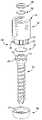
- FIG. 1is a perspective view of an exemplary multi-axial screw assembly according to the present teachings
- FIG. 2is a perspective view of an exemplary bone screw of the multi-axial screw assembly of FIG. 1 ;
- FIGS. 3A and 3Bare perspective views of a receiver for the multi-axial screw assembly of FIG. 1 ;
- FIGS. 4A and 4Bare perspective views of a sleeve for the multi-axial screw assembly of FIG. 1 ;
- FIG. 5Ais a perspective view of a cap for the multi-axial screw assembly of FIG. 1 ;
- FIG. 5Bis a side view of the cap of FIG. 5A ;
- FIG. 6is a perspective view of a cap-retaining ring for the multi-axial screw assembly of FIG. 1 ;
- FIG. 7is a perspective view of a bone screw ring for the multi-axial screw assembly of FIG. 1 ;
- FIG. 8Ais an exploded view of an exemplary multi-axial screw assembly according to the present teachings.
- FIGS. 8B-Dillustrate various aspects of assembling the multi-axial screw assembly of FIG. 8A ;
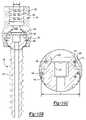
- FIG. 9is a bottom perspective view of the multi-axial screw assembly of FIG. 8D ;
- FIG. 10Ais a side view of the multi-axial screw assembly of FIG. 9 ;
- FIG. 10Bis a sectional view of the multi-axial screw assembly of FIG. 9 ;
- FIG. 10Cis an enlarged view of Detail 10 C of FIG. 10B .
- an exemplary multi-axial bone fixation device 100is illustrated as assembled with a spinal connecting element 109 .
- the connecting element 109can be in the form of a rod or bar or other elongated element.
- the connecting element 109is illustrated as straight, it will be appreciated that the connecting element 109 can be also curved and can have a curvature following, for example, the natural curvature of the spine.
- the bone fixation device 100can generally include a bone fastener 102 , a receiver 104 , a hollow retaining member or sleeve 106 , an annular element 140 and first and second retention elements 160 , 150 shown in the form of split rings. Additional views of these components are illustrated in FIGS. 3A-7 and 9 - 10 C.
- the bone fastener 102can include a head 110 and a bone-engaging elongated portion 114 that can include ridges, threads or other anchoring formations 116 along at least a portion of its length.
- the elongated portion 114can include one or more cutting flutes 118 at its distal end.
- the head 110 of the bone fastener 102can define a first circumferential groove 108 for at least partially receiving the first retention element 160 .
- the head 110can include a protrusion 119 having an internal driver-engagement surface 112 for engaging a conventional or other insertion tool (not shown).
- the engagement surface 112can include straight or curved drive faces. In the exemplary illustration of FIG. 2 , a five-lobe (pentalobe) engagement surface 112 is shown for use with an insertion tool having complementary driver surfaces.
- the receiver 104can define an axial opening comprising an upper opening 105 and a lower opening 103 along a longitudinal axis A.
- the receiver 104can also include an upper portion 121 comprising two arms 120 and defining a U-shaped transverse opening 101 along a transverse axis B.
- Each of the arms 120can define inner engagement formations 128 , such as threads, ridges, or grooves.
- the transverse opening 101can be configured to receive a connecting element, such as the connecting element 109 shown in FIG. 1 .
- the receiver 104can include a radially compressible lower portion 123 in the form of a socket defined by a plurality of spaced apart elongated elements or fingers 124 .
- Each elongated element 124can include an outward flange 126 directed radially away from the lower opening 103 .
- the elongated elements 124can be resiliently deflected inward toward the longitudinal axis A for receiving the hollow member 106 .
- the hollow member 106can include an annular upper face 130 , an annular lower face 132 , and a peripheral wall 134 between the upper and lower faces 130 , 132 .
- the peripheral wall 134can be tapered from the upper face 130 to the lower face 132 , and can define an inner step or notch or other circumferential discontinuity 131 .
- the hollow member 106can be inserted around the compressible lower portion 123 such that the flanges 126 engage the discontinuity 131 and the elongated members 124 are urged radially inwards securing the hollow member 106 over the receiver 104 in a snap-fit or other engagement.
- the annular member 140can include a peripheral or side wall 144 between upper and lower surfaces 146 , 148 .
- the peripheral wall 144defines an opening 117 through the annular member 140 .
- the annular member 140can define a second outer circumferential groove 142 on the peripheral wall 144 for at least partially receiving the second retention element 150 .
- an exemplary procedure for assembling the multi-axial fixation device 100can include assembling the first retention element 160 in the first circumferential groove 108 of the head 110 of the bone fastener 102 , as shown in FIG. 8B , and inserting the bone fastener 102 from the lower portion 123 of the receiver 104 into the lower opening 103 , as shown in FIG. 8C .
- the elongated elements 124 in their relaxed statescan cooperate to define an opening 103 larger than the diameter of the head 110 .
- the hollow member 106can be pushed over the lower portion 123 until the flanges 126 of the elongated elements 124 snap into the discontinuity 131 radially compressing the lower portion 123 .
- a major diameter D of the head 110can exceed a minor diameter “d” of the receiver 104 .
- the minor diameter dcan correspond to the engagement formations 128 .
- the fastener 102can angulate relative to the first longitudinal axis A of the receiver 104 , as shown in FIG. 8D in phantom lines.
- the first retention element 160can provide frictional resistance to rotation of the bone fastener 102 relative to the receiver 104 .
- the second retention element 150can be assembled in the second circumferential groove 142 of the annular element 140 , which can be inserted from the upper portion 121 of the receiver 104 and positioned to contact the head 110 of the bone fastener 102 , as shown in FIG. 8D .
- the annular member 140can be seated around the protrusion 119 of the head 110 of the bone fastener 102 , such that the protrusion 119 is inserted in the opening 117 defined by the peripheral wall 144 .
- the second retention element 150can retain the annular member 140 in the receiver 104 and can be supported between the second circumferential groove 142 and a notch 170 defined in an abutting inner surface of the receiver 104 , as shown in FIGS. 10B and 10C .
- the connecting element 109can be inserted along the transverse axis B in the transverse opening 101 of the receiver 104 .
- a securing or locking member 113in the form of a set screw or other plug, for example, can be inserted through the upper opening 105 of the receiver 104 .
- the securing member 113can include engagement formations 111 complimentary to the engagement formations 128 of the receiver 104 , and a driver-receiving inner surface 107 .
- the engagement formations 111can comprise a helical flange, for example.
- a drivercan be coupled to the driver-receiving surface 107 and rotated to drive the securing member 113 against the connecting element 109 , thereby transmitting compression through the annular element 140 to the head 110 of the bone fastener 102 and securing the bone fastener 102 in a pre-selected angulation position.
- the multi-axial bone fixation device 100can be used with bone fasteners 102 having different sizes or shapes, or of different types, with or without flutes 118 or other cutting ridges.
- the extent and/or type of anchoring formations 116can be varied, as well as the size and geometry of the head 110 , etc.
- the present teachingsallow quick loading of the bone fastener 102 from the lower portion 123 of the receiver and still maintain a high degree of angulation similar to top-loading bone fasteners. Further, the present teachings allow a major diameter D of the head of the bone fastener 102 to exceed a minor diameter d that is associated with the engagement formations 128 for the securing element 113 . Thus the present teaching can prevent bone fastener back out.
Landscapes
- Health & Medical Sciences (AREA)
- Orthopedic Medicine & Surgery (AREA)
- Life Sciences & Earth Sciences (AREA)
- Neurology (AREA)
- Surgery (AREA)
- Heart & Thoracic Surgery (AREA)
- Engineering & Computer Science (AREA)
- Biomedical Technology (AREA)
- Nuclear Medicine, Radiotherapy & Molecular Imaging (AREA)
- Medical Informatics (AREA)
- Molecular Biology (AREA)
- Animal Behavior & Ethology (AREA)
- General Health & Medical Sciences (AREA)
- Public Health (AREA)
- Veterinary Medicine (AREA)
- Surgical Instruments (AREA)
- Prostheses (AREA)
Abstract
Description
Claims (22)
Priority Applications (3)
| Application Number | Priority Date | Filing Date | Title |
|---|---|---|---|
| US11/594,316US7699876B2 (en) | 2006-11-08 | 2006-11-08 | Multi-axial bone fixation apparatus |
| EP07861779.2AEP2097025B1 (en) | 2006-11-08 | 2007-11-07 | Multi-axial bone fixation apparatus |
| PCT/US2007/023423WO2008057551A2 (en) | 2006-11-08 | 2007-11-07 | Multi-axial bone fixation apparatus |
Applications Claiming Priority (1)
| Application Number | Priority Date | Filing Date | Title |
|---|---|---|---|
| US11/594,316US7699876B2 (en) | 2006-11-08 | 2006-11-08 | Multi-axial bone fixation apparatus |
Publications (2)
| Publication Number | Publication Date |
|---|---|
| US20080108992A1 US20080108992A1 (en) | 2008-05-08 |
| US7699876B2true US7699876B2 (en) | 2010-04-20 |
Family
ID=39205293
Family Applications (1)
| Application Number | Title | Priority Date | Filing Date |
|---|---|---|---|
| US11/594,316Active2028-08-21US7699876B2 (en) | 2006-11-08 | 2006-11-08 | Multi-axial bone fixation apparatus |
Country Status (3)
| Country | Link |
|---|---|
| US (1) | US7699876B2 (en) |
| EP (1) | EP2097025B1 (en) |
| WO (1) | WO2008057551A2 (en) |
Cited By (73)
| Publication number | Priority date | Publication date | Assignee | Title |
|---|---|---|---|---|
| US20060161152A1 (en)* | 2004-10-25 | 2006-07-20 | Alphaspine, Inc. | Bone fixation systems and methods of assembling and/or installing the same |
| US20070233078A1 (en)* | 2006-01-27 | 2007-10-04 | Justis Jeff R | Pivoting joints for spinal implants including designed resistance to motion and methods of use |
| US20080045953A1 (en)* | 2006-07-14 | 2008-02-21 | Laszlo Garamszegi | Pedicle screw assembly with inclined surface seat |
| US20110046683A1 (en)* | 2009-08-20 | 2011-02-24 | Lutz Biedermann | Bone anchoring device, tool and method for assembling the same and tool for use with the same |
| US20110112578A1 (en)* | 2009-11-09 | 2011-05-12 | Ebi, Llc | Multiplanar bone anchor system |
| US8057519B2 (en) | 2006-01-27 | 2011-11-15 | Warsaw Orthopedic, Inc. | Multi-axial screw assembly |
| US20120016425A1 (en)* | 2009-11-09 | 2012-01-19 | Ebi, Llc | Multiplanar bone anchor system |
| US20120172932A1 (en)* | 2010-12-10 | 2012-07-05 | Lutz Biedermann | Bone anchoring device |
| US20120179211A1 (en)* | 2010-12-10 | 2012-07-12 | Lutz Biedermann | Receiving part for receiving a rod for coupling the rod to a bone anchoring element and bone anchoring device with such a receiving part |
| US8298270B2 (en) | 2006-01-27 | 2012-10-30 | Warsaw Orthopedic, Inc. | Pivoting joints for spinal implants including designed resistance to motion and methods of use |
| US8377067B2 (en) | 2004-02-27 | 2013-02-19 | Roger P. Jackson | Orthopedic implant rod reduction tool set and method |
| WO2013033205A1 (en) | 2011-08-31 | 2013-03-07 | Biomet Manufacturing Corp. | Patient-specific sacroiliac guides and associated methods |
| US8394133B2 (en) | 2004-02-27 | 2013-03-12 | Roger P. Jackson | Dynamic fixation assemblies with inner core and outer coil-like member |
| US8444681B2 (en) | 2009-06-15 | 2013-05-21 | Roger P. Jackson | Polyaxial bone anchor with pop-on shank, friction fit retainer and winged insert |
| US20130150852A1 (en)* | 2010-08-30 | 2013-06-13 | Zimmer Spine, Inc. | Polyaxial pedicle screw |
| US8556938B2 (en) | 2009-06-15 | 2013-10-15 | Roger P. Jackson | Polyaxial bone anchor with non-pivotable retainer and pop-on shank, some with friction fit |
| US8663291B2 (en) | 2011-10-28 | 2014-03-04 | Ortho Innovations, Llc | Top loading polyaxial ball and socket fastener |
| WO2014070889A1 (en) | 2012-10-31 | 2014-05-08 | Biomet Manufacturing, Llc | Patient-specific sacroiliac and pedicle guides |
| US8814911B2 (en) | 2003-06-18 | 2014-08-26 | Roger P. Jackson | Polyaxial bone screw with cam connection and lock and release insert |
| WO2014159177A1 (en) | 2013-03-14 | 2014-10-02 | Ebi, Llc | Torque multiplier, limiter, and counter-torque combinations and methods |
| US8894657B2 (en) | 2004-02-27 | 2014-11-25 | Roger P. Jackson | Tool system for dynamic spinal implants |
| US8911479B2 (en) | 2012-01-10 | 2014-12-16 | Roger P. Jackson | Multi-start closures for open implants |
| US8992579B1 (en) | 2011-03-08 | 2015-03-31 | Nuvasive, Inc. | Lateral fixation constructs and related methods |
| US8998959B2 (en) | 2009-06-15 | 2015-04-07 | Roger P Jackson | Polyaxial bone anchors with pop-on shank, fully constrained friction fit retainer and lock and release insert |
| US9050139B2 (en) | 2004-02-27 | 2015-06-09 | Roger P. Jackson | Orthopedic implant rod reduction tool set and method |
| US9060815B1 (en) | 2012-03-08 | 2015-06-23 | Nuvasive, Inc. | Systems and methods for performing spine surgery |
| US9161745B2 (en) | 2011-10-05 | 2015-10-20 | Mark A. Dodson | Modular retractor and related method |
| US9168069B2 (en) | 2009-06-15 | 2015-10-27 | Roger P. Jackson | Polyaxial bone anchor with pop-on shank and winged insert with lower skirt for engaging a friction fit retainer |
| US9211150B2 (en) | 2004-11-23 | 2015-12-15 | Roger P. Jackson | Spinal fixation tool set and method |
| US9216039B2 (en) | 2004-02-27 | 2015-12-22 | Roger P. Jackson | Dynamic spinal stabilization assemblies, tool set and method |
| US9393047B2 (en) | 2009-06-15 | 2016-07-19 | Roger P. Jackson | Polyaxial bone anchor with pop-on shank and friction fit retainer with low profile edge lock |
| USRE46115E1 (en) | 2005-09-19 | 2016-08-23 | Ebi, Llc | Bone screw apparatus, system and method |
| US9480517B2 (en) | 2009-06-15 | 2016-11-01 | Roger P. Jackson | Polyaxial bone anchor with pop-on shank, shank, friction fit retainer, winged insert and low profile edge lock |
| US9517089B1 (en) | 2013-10-08 | 2016-12-13 | Nuvasive, Inc. | Bone anchor with offset rod connector |
| US9713488B2 (en) | 2008-02-04 | 2017-07-25 | Medos International Sarl | Methods for correction of spinal deformities |
| US9724145B2 (en) | 2013-03-14 | 2017-08-08 | Medos International Sarl | Bone anchor assemblies with multiple component bottom loading bone anchors |
| US9724130B2 (en) | 2013-03-14 | 2017-08-08 | Medos International Sarl | Locking compression members for use with bone anchor assemblies and methods |
| US9743957B2 (en) | 2004-11-10 | 2017-08-29 | Roger P. Jackson | Polyaxial bone screw with shank articulation pressure insert and method |
| US9775660B2 (en) | 2013-03-14 | 2017-10-03 | DePuy Synthes Products, Inc. | Bottom-loading bone anchor assemblies and methods |
| US9782204B2 (en) | 2012-09-28 | 2017-10-10 | Medos International Sarl | Bone anchor assemblies |
| US9907574B2 (en) | 2008-08-01 | 2018-03-06 | Roger P. Jackson | Polyaxial bone anchors with pop-on shank, friction fit fully restrained retainer, insert and tool receiving features |
| US9918747B2 (en) | 2013-03-14 | 2018-03-20 | DePuy Synthes Products, Inc. | Bone anchor assemblies and methods with improved locking |
| US9980753B2 (en) | 2009-06-15 | 2018-05-29 | Roger P Jackson | pivotal anchor with snap-in-place insert having rotation blocking extensions |
| US10039578B2 (en) | 2003-12-16 | 2018-08-07 | DePuy Synthes Products, Inc. | Methods and devices for minimally invasive spinal fixation element placement |
| US10039577B2 (en) | 2004-11-23 | 2018-08-07 | Roger P Jackson | Bone anchor receiver with horizontal radiused tool attachment structures and parallel planar outer surfaces |
| US10076362B2 (en) | 2012-07-18 | 2018-09-18 | Biedermann Technologies Gmbh & Co. Kg | Polyaxial bone anchoring device |
| US20180325569A1 (en)* | 2017-05-10 | 2018-11-15 | Medos International Sarl | Bone anchors with drag features and related methods |
| US10194951B2 (en) | 2005-05-10 | 2019-02-05 | Roger P. Jackson | Polyaxial bone anchor with compound articulation and pop-on shank |
| US10299839B2 (en) | 2003-12-16 | 2019-05-28 | Medos International Sárl | Percutaneous access devices and bone anchor assemblies |
| US10342582B2 (en) | 2013-03-14 | 2019-07-09 | DePuy Synthes Products, Inc. | Bone anchor assemblies and methods with improved locking |
| US10363070B2 (en) | 2009-06-15 | 2019-07-30 | Roger P. Jackson | Pivotal bone anchor assemblies with pressure inserts and snap on articulating retainers |
| US10485588B2 (en) | 2004-02-27 | 2019-11-26 | Nuvasive, Inc. | Spinal fixation tool attachment structure |
| US10610265B1 (en) | 2017-07-31 | 2020-04-07 | K2M, Inc. | Polyaxial bone screw with increased angulation |
| US10675061B2 (en) | 2016-02-26 | 2020-06-09 | Medos International Sarl | Polyaxial bone fixation element |
| US11141197B2 (en)* | 2019-06-24 | 2021-10-12 | DePuy Synthes Products, Inc. | Polyaxial strut for external fixation |
| US11241261B2 (en) | 2005-09-30 | 2022-02-08 | Roger P Jackson | Apparatus and method for soft spinal stabilization using a tensionable cord and releasable end structure |
| US11304728B2 (en)* | 2020-02-14 | 2022-04-19 | Medos International Sarl | Integrated multipoint fixation screw |
| US11419642B2 (en) | 2003-12-16 | 2022-08-23 | Medos International Sarl | Percutaneous access devices and bone anchor assemblies |
| US11426210B2 (en) | 2019-09-25 | 2022-08-30 | Medos International Sàrl | Multipoint angled fixation implants for multiple screws and related methods |
| US11602377B2 (en)* | 2019-11-14 | 2023-03-14 | Biedermann Technologies Gmbh & Co. Kg | Receiving part for coupling a rod to a bone anchor |
| US20230240724A1 (en)* | 2019-05-22 | 2023-08-03 | Nuvasive, Inc. | Posterior spinal fixation screws |
| US11717327B2 (en) | 2018-03-20 | 2023-08-08 | Medos International Sarl | Multipoint fixation implants and related methods |
| US11974784B2 (en) | 2016-03-17 | 2024-05-07 | Medos International Sàrl | Multipoint fixation implants |
| US12064148B2 (en) | 2016-09-16 | 2024-08-20 | Mirus Llc | Bone anchor, instruments, and methods for use |
| US12082850B2 (en) | 2007-09-17 | 2024-09-10 | Roger P. Jackson | Pivotal bone anchor assembly having twist-in-place insert and receiver with pre-formed axial rotation insert stops |
| US12096964B2 (en) | 2021-07-09 | 2024-09-24 | Roger P. Jackson | Modular bone anchor system with bottom loaded shank heads having a single shank head shape |
| US12127766B2 (en) | 2021-03-05 | 2024-10-29 | Medos International Sàrl | Selectively locking polyaxial screw |
| US12167872B2 (en) | 2014-10-21 | 2024-12-17 | Roger P. Jackson | Bottom loaded pivotal bone anchor assembly with locking and blocking rings and insert tool deployment |
| US12251139B2 (en) | 2007-05-23 | 2025-03-18 | Roger P. Jackson | Pivotal bone anchor screw with nested two-piece closure and independent locking twist-in-place insert |
| US12310631B2 (en) | 2021-03-05 | 2025-05-27 | Medos International Sárl | Multi-feature polyaxial screw |
| US12329422B2 (en) | 2010-05-14 | 2025-06-17 | Roger P. Jackson | Pivotal bone anchor assembly with resiliently axially compressible shank head and rod engaging insert |
| US12357348B2 (en) | 2005-09-30 | 2025-07-15 | Roger P. Jackson | Method of assembling a pivotal bone anchor assembly with press-in-place insert |
| US12440245B2 (en) | 2023-09-06 | 2025-10-14 | Pivotable bone anchor assembly with independent provisional locking by insert compressing member |
Families Citing this family (64)
| Publication number | Priority date | Publication date | Assignee | Title |
|---|---|---|---|---|
| US7833250B2 (en) | 2004-11-10 | 2010-11-16 | Jackson Roger P | Polyaxial bone screw with helically wound capture connection |
| US10729469B2 (en) | 2006-01-09 | 2020-08-04 | Roger P. Jackson | Flexible spinal stabilization assembly with spacer having off-axis core member |
| US10258382B2 (en) | 2007-01-18 | 2019-04-16 | Roger P. Jackson | Rod-cord dynamic connection assemblies with slidable bone anchor attachment members along the cord |
| US8292926B2 (en) | 2005-09-30 | 2012-10-23 | Jackson Roger P | Dynamic stabilization connecting member with elastic core and outer sleeve |
| US8876868B2 (en) | 2002-09-06 | 2014-11-04 | Roger P. Jackson | Helical guide and advancement flange with radially loaded lip |
| WO2006052796A2 (en) | 2004-11-10 | 2006-05-18 | Jackson Roger P | Helical guide and advancement flange with break-off extensions |
| US7377923B2 (en) | 2003-05-22 | 2008-05-27 | Alphatec Spine, Inc. | Variable angle spinal screw assembly |
| US8137386B2 (en) | 2003-08-28 | 2012-03-20 | Jackson Roger P | Polyaxial bone screw apparatus |
| US20110040338A1 (en)* | 2003-08-28 | 2011-02-17 | Jackson Roger P | Polyaxial bone anchor having an open retainer with conical, cylindrical or curvate capture |
| US7967850B2 (en) | 2003-06-18 | 2011-06-28 | Jackson Roger P | Polyaxial bone anchor with helical capture connection, insert and dual locking assembly |
| US8377102B2 (en) | 2003-06-18 | 2013-02-19 | Roger P. Jackson | Polyaxial bone anchor with spline capture connection and lower pressure insert |
| US8398682B2 (en) | 2003-06-18 | 2013-03-19 | Roger P. Jackson | Polyaxial bone screw assembly |
| US8926670B2 (en) | 2003-06-18 | 2015-01-06 | Roger P. Jackson | Polyaxial bone screw assembly |
| WO2005094707A2 (en)* | 2004-03-26 | 2005-10-13 | Smith & Nephew, Inc. | Methods for treating fractures of the femur and femoral fracture devices |
| US7651502B2 (en) | 2004-09-24 | 2010-01-26 | Jackson Roger P | Spinal fixation tool set and method for rod reduction and fastener insertion |
| US8926672B2 (en) | 2004-11-10 | 2015-01-06 | Roger P. Jackson | Splay control closure for open bone anchor |
| US9216041B2 (en) | 2009-06-15 | 2015-12-22 | Roger P. Jackson | Spinal connecting members with tensioned cords and rigid sleeves for engaging compression inserts |
| US8308782B2 (en) | 2004-11-23 | 2012-11-13 | Jackson Roger P | Bone anchors with longitudinal connecting member engaging inserts and closures for fixation and optional angulation |
| US10076361B2 (en) | 2005-02-22 | 2018-09-18 | Roger P. Jackson | Polyaxial bone screw with spherical capture, compression and alignment and retention structures |
| US7901437B2 (en) | 2007-01-26 | 2011-03-08 | Jackson Roger P | Dynamic stabilization member with molded connection |
| US8105368B2 (en) | 2005-09-30 | 2012-01-31 | Jackson Roger P | Dynamic stabilization connecting member with slitted core and outer sleeve |
| US8366745B2 (en) | 2007-05-01 | 2013-02-05 | Jackson Roger P | Dynamic stabilization assembly having pre-compressed spacers with differential displacements |
| US8475498B2 (en) | 2007-01-18 | 2013-07-02 | Roger P. Jackson | Dynamic stabilization connecting member with cord connection |
| US10383660B2 (en) | 2007-05-01 | 2019-08-20 | Roger P. Jackson | Soft stabilization assemblies with pretensioned cords |
| ES2348814T3 (en) | 2007-07-31 | 2010-12-15 | Biedermann Motech Gmbh | ANCHORAGE DEVICE Ã “SEO. |
| US20090069852A1 (en)* | 2007-09-06 | 2009-03-12 | Warsaw Orthopedic, Inc. | Multi-Axial Bone Anchor Assembly |
| US20090082812A1 (en)* | 2007-09-21 | 2009-03-26 | Lewis Trevor K | Provisional locking pedicle screw system and method |
| JP2010099293A (en)* | 2008-10-24 | 2010-05-06 | Japan Medical Materials Corp | Bone anchor unit for vertebral column fixation and method for manufacturing the same |
| US8603145B2 (en)* | 2008-12-16 | 2013-12-10 | Zimmer Spine, Inc. | Coaxially lockable poly-axial bone fastener assemblies |
| ES2375879T3 (en)* | 2008-12-23 | 2012-03-07 | Biedermann Motech Gmbh | RECEPTION AREA OF A ROD FOR COUPLING THE ROD IN AN BONE ANCHORAGE ELEMENT AND BONE ANCHORAGE DEVICE WITH SUCH RECEPTION AREA. |
| ES2378588T3 (en) | 2008-12-30 | 2012-04-16 | Biedermann Motech Gmbh | Receiving part for receiving a rod for coupling the rod in a bone anchoring element and bone anchoring device with such receiving part |
| FR2942951B1 (en)* | 2009-03-12 | 2012-03-30 | Euros Sa | SPINAL IMPLANT WITH LOCKING BALL JOINT |
| US11229457B2 (en) | 2009-06-15 | 2022-01-25 | Roger P. Jackson | Pivotal bone anchor assembly with insert tool deployment |
| US9668771B2 (en) | 2009-06-15 | 2017-06-06 | Roger P Jackson | Soft stabilization assemblies with off-set connector |
| US20110106181A1 (en)* | 2009-10-30 | 2011-05-05 | Warsaw Orthopedic, Inc. | Adjustable saddle for a bone anchor |
| US20110202094A1 (en)* | 2009-11-11 | 2011-08-18 | Pereira Mario L | Trans-polyaxial screw |
| EP2384709B1 (en)* | 2010-05-05 | 2012-09-05 | Biedermann Technologies GmbH & Co. KG | Receiving part for receiving a rod for coupling the rod to a bone anchoring element, bone anchoring device, method and tool for assembling the same |
| AU2011299558A1 (en) | 2010-09-08 | 2013-05-02 | Roger P. Jackson | Dynamic stabilization members with elastic and inelastic sections |
| EP2574297B1 (en) | 2011-09-30 | 2015-11-11 | Biedermann Technologies GmbH & Co. KG | Bone anchoring device and tool cooperating with such a bone anchoring device |
| ES2552987T3 (en)* | 2012-07-03 | 2015-12-03 | Biedermann Technologies Gmbh & Co. Kg | Polyaxial bone anchoring device |
| US8911478B2 (en) | 2012-11-21 | 2014-12-16 | Roger P. Jackson | Splay control closure for open bone anchor |
| US10058354B2 (en) | 2013-01-28 | 2018-08-28 | Roger P. Jackson | Pivotal bone anchor assembly with frictional shank head seating surfaces |
| US8852239B2 (en) | 2013-02-15 | 2014-10-07 | Roger P Jackson | Sagittal angle screw with integral shank and receiver |
| EP2851021B1 (en) | 2013-09-19 | 2016-12-14 | Biedermann Technologies GmbH & Co. KG | Coupling assembly for coupling a rod to a bone anchoring element, polyaxial bone anchoring device and modular stabilization device |
| US9987047B2 (en) | 2013-10-07 | 2018-06-05 | Spine Wave, Inc. | Translating polyaxial screw |
| US9566092B2 (en)* | 2013-10-29 | 2017-02-14 | Roger P. Jackson | Cervical bone anchor with collet retainer and outer locking sleeve |
| US9717533B2 (en) | 2013-12-12 | 2017-08-01 | Roger P. Jackson | Bone anchor closure pivot-splay control flange form guide and advancement structure |
| US9498255B2 (en)* | 2013-12-31 | 2016-11-22 | Blackstone Medical, Inc. | Translational pedicle screw systems |
| US9451993B2 (en) | 2014-01-09 | 2016-09-27 | Roger P. Jackson | Bi-radial pop-on cervical bone anchor |
| US10064658B2 (en) | 2014-06-04 | 2018-09-04 | Roger P. Jackson | Polyaxial bone anchor with insert guides |
| US9597119B2 (en) | 2014-06-04 | 2017-03-21 | Roger P. Jackson | Polyaxial bone anchor with polymer sleeve |
| US9707013B2 (en)* | 2015-04-30 | 2017-07-18 | Warsaw Orthopedic, Inc. | Spinal implant system and methods of use |
| EP3278750B1 (en) | 2016-08-04 | 2018-12-12 | Biedermann Technologies GmbH & Co. KG | Polyaxial bone anchoring device and system of an instrument and a polyaxial bone anchoring device |
| EP3287089B1 (en)* | 2016-08-24 | 2019-07-24 | Biedermann Technologies GmbH & Co. KG | Polyaxial bone anchoring device and system of an instrument and a polyaxial bone anchoring device |
| US10258386B2 (en)* | 2017-06-15 | 2019-04-16 | Warsaw Orthopedic, Inc. | Spinal construct and method |
| EP3476340B1 (en) | 2017-10-25 | 2021-06-02 | Biedermann Technologies GmbH & Co. KG | Polyaxial bone anchoring device |
| US10695100B2 (en) | 2017-12-15 | 2020-06-30 | Warsaw Orthopedic, Inc. | Spinal implant system and methods of use |
| US10695102B2 (en) | 2017-12-15 | 2020-06-30 | Warsaw Orthopedic, Inc. | Spinal implant system and methods of use |
| EP3536271B1 (en)* | 2018-03-06 | 2022-05-04 | Biedermann Technologies GmbH & Co. KG | Polyaxial bone anchoring device and system of an instrument and a polyaxial bone anchoring device |
| US10687858B2 (en) | 2018-11-08 | 2020-06-23 | Warsaw Orthopedic, Inc. | Spinal implant system and methods of use |
| US10918421B2 (en)* | 2019-05-07 | 2021-02-16 | Warsaw Orthopedic, Inc. | Spinal implant system and methods of use |
| US11376046B1 (en) | 2021-02-01 | 2022-07-05 | Warsaw Orthopedic, Inc. | Spinal implant system and method |
| EP4129220B1 (en)* | 2021-08-04 | 2024-07-03 | Biedermann Technologies GmbH & Co. KG | Coupling device for coupling a rod to a bone anchoring element and method of manufacturing the same |
| US20240398444A1 (en)* | 2021-09-14 | 2024-12-05 | Agmspine, Sia | A polyaxial spinal screw |
Citations (23)
| Publication number | Priority date | Publication date | Assignee | Title |
|---|---|---|---|---|
| US4946458A (en) | 1986-04-25 | 1990-08-07 | Harms Juergen | Pedicle screw |
| US5549608A (en) | 1995-07-13 | 1996-08-27 | Fastenetix, L.L.C. | Advanced polyaxial locking screw and coupling element device for use with rod fixation apparatus |
| US5728098A (en) | 1996-11-07 | 1998-03-17 | Sdgi Holdings, Inc. | Multi-angle bone screw assembly using shape-memory technology |
| US5733285A (en) | 1995-07-13 | 1998-03-31 | Fastenetix, Llc | Polyaxial locking mechanism |
| US5817094A (en) | 1995-04-13 | 1998-10-06 | Fastenetix, Llc | Polyaxial locking screw and coupling element |
| US6010503A (en) | 1998-04-03 | 2000-01-04 | Spinal Innovations, Llc | Locking mechanism |
| US6132432A (en) | 1996-10-18 | 2000-10-17 | Spinal Innovations Llc | Spinal implant fixation assembly |
| WO2000072770A1 (en) | 1999-05-28 | 2000-12-07 | Sdgi Holdings, Inc. | Shape-memory coupling especially for spinal fixator |
| US6273888B1 (en)* | 1999-05-28 | 2001-08-14 | Sdgi Holdings, Inc. | Device and method for selectively preventing the locking of a shape-memory alloy coupling system |
| US6280442B1 (en)* | 1999-09-01 | 2001-08-28 | Sdgi Holdings, Inc. | Multi-axial bone screw assembly |
| US20010047173A1 (en)* | 1998-09-29 | 2001-11-29 | Fridolin Schlapfer | Device for connecting a longitudinal support to a bone anchor |
| US6371957B1 (en) | 1997-01-22 | 2002-04-16 | Synthes (Usa) | Device for connecting a longitudinal bar to a pedicle screw |
| US20040176766A1 (en)* | 2002-02-13 | 2004-09-09 | Shluzas Alan E. | Apparatus for connecting a longitudinal member to a bone portion |
| WO2004089245A2 (en) | 2003-04-04 | 2004-10-21 | Theken Surgical, Llc | Bone anchor |
| WO2005018471A1 (en) | 2003-08-20 | 2005-03-03 | Sdgi Holdings, Inc. | Multi-axial orthopedic device and system, e.g. for spinal surgery |
| US20050080415A1 (en)* | 2003-10-14 | 2005-04-14 | Keyer Thomas R. | Polyaxial bone anchor and method of spinal fixation |
| US20050096653A1 (en) | 2003-11-03 | 2005-05-05 | Doubler Robert L. | Bone fixation system with low profile fastener |
| US20050228392A1 (en) | 2004-04-12 | 2005-10-13 | Keyer Thomas R | Rod persuader |
| WO2005096968A1 (en) | 2004-03-31 | 2005-10-20 | Endius, Inc. | Access device having discrete visualization locations |
| WO2006047555A2 (en) | 2004-10-25 | 2006-05-04 | Alphaspine, Inc. | Bone fixation systems and methods |
| WO2006060585A1 (en) | 2004-12-01 | 2006-06-08 | Sdgi Holdings, Inc. | Side-loading bone anchor |
| US20060129149A1 (en) | 2004-04-08 | 2006-06-15 | Andrew Iott | Polyaxial screw |
| US20070118117A1 (en) | 2005-10-20 | 2007-05-24 | Ebi, L.P. | Bone fixation assembly |
- 2006
- 2006-11-08USUS11/594,316patent/US7699876B2/enactiveActive
- 2007
- 2007-11-07WOPCT/US2007/023423patent/WO2008057551A2/enactiveApplication Filing
- 2007-11-07EPEP07861779.2Apatent/EP2097025B1/ennot_activeNot-in-force
Patent Citations (31)
| Publication number | Priority date | Publication date | Assignee | Title |
|---|---|---|---|---|
| US4946458A (en) | 1986-04-25 | 1990-08-07 | Harms Juergen | Pedicle screw |
| US5817094A (en) | 1995-04-13 | 1998-10-06 | Fastenetix, Llc | Polyaxial locking screw and coupling element |
| US5549608A (en) | 1995-07-13 | 1996-08-27 | Fastenetix, L.L.C. | Advanced polyaxial locking screw and coupling element device for use with rod fixation apparatus |
| US5733285A (en) | 1995-07-13 | 1998-03-31 | Fastenetix, Llc | Polyaxial locking mechanism |
| US6132432A (en) | 1996-10-18 | 2000-10-17 | Spinal Innovations Llc | Spinal implant fixation assembly |
| US6454773B1 (en) | 1996-11-07 | 2002-09-24 | Sdgi Holdings, Inc. | Multi-angle bone screw assembly using shape-memory technology |
| US5728098A (en) | 1996-11-07 | 1998-03-17 | Sdgi Holdings, Inc. | Multi-angle bone screw assembly using shape-memory technology |
| US5954725A (en) | 1996-11-07 | 1999-09-21 | Sdgi Holdings, Inc. | Multi-angle bone screw assembly using shape memory technology |
| US6287311B1 (en) | 1996-11-07 | 2001-09-11 | Sdgi Holdings, Inc. | Multi-angle bone screw assembly using shape-memory technology |
| US6132434A (en) | 1996-11-07 | 2000-10-17 | Sdgi Holdings, Inc. | Multi-angle bone screw assembly using shape-memory technology |
| US7022122B2 (en) | 1997-01-22 | 2006-04-04 | Synthes (U.S.A.) | Device for connecting a longitudinal bar to a pedicle screw |
| US6371957B1 (en) | 1997-01-22 | 2002-04-16 | Synthes (Usa) | Device for connecting a longitudinal bar to a pedicle screw |
| US6355040B1 (en) | 1998-04-03 | 2002-03-12 | Spinal Innovations, L.L.C. | Locking mechanism |
| US6010503A (en) | 1998-04-03 | 2000-01-04 | Spinal Innovations, Llc | Locking mechanism |
| US20010047173A1 (en)* | 1998-09-29 | 2001-11-29 | Fridolin Schlapfer | Device for connecting a longitudinal support to a bone anchor |
| US6273888B1 (en)* | 1999-05-28 | 2001-08-14 | Sdgi Holdings, Inc. | Device and method for selectively preventing the locking of a shape-memory alloy coupling system |
| US6254602B1 (en) | 1999-05-28 | 2001-07-03 | Sdgi Holdings, Inc. | Advanced coupling device using shape-memory technology |
| WO2000072770A1 (en) | 1999-05-28 | 2000-12-07 | Sdgi Holdings, Inc. | Shape-memory coupling especially for spinal fixator |
| US6280442B1 (en)* | 1999-09-01 | 2001-08-28 | Sdgi Holdings, Inc. | Multi-axial bone screw assembly |
| US20040176766A1 (en)* | 2002-02-13 | 2004-09-09 | Shluzas Alan E. | Apparatus for connecting a longitudinal member to a bone portion |
| WO2004089245A2 (en) | 2003-04-04 | 2004-10-21 | Theken Surgical, Llc | Bone anchor |
| WO2005018471A1 (en) | 2003-08-20 | 2005-03-03 | Sdgi Holdings, Inc. | Multi-axial orthopedic device and system, e.g. for spinal surgery |
| US20050080415A1 (en)* | 2003-10-14 | 2005-04-14 | Keyer Thomas R. | Polyaxial bone anchor and method of spinal fixation |
| WO2005041821A2 (en) | 2003-11-03 | 2005-05-12 | Spinal, Llc | Bone fixation system with low profile fastener |
| US20050096653A1 (en) | 2003-11-03 | 2005-05-05 | Doubler Robert L. | Bone fixation system with low profile fastener |
| WO2005096968A1 (en) | 2004-03-31 | 2005-10-20 | Endius, Inc. | Access device having discrete visualization locations |
| US20060129149A1 (en) | 2004-04-08 | 2006-06-15 | Andrew Iott | Polyaxial screw |
| US20050228392A1 (en) | 2004-04-12 | 2005-10-13 | Keyer Thomas R | Rod persuader |
| WO2006047555A2 (en) | 2004-10-25 | 2006-05-04 | Alphaspine, Inc. | Bone fixation systems and methods |
| WO2006060585A1 (en) | 2004-12-01 | 2006-06-08 | Sdgi Holdings, Inc. | Side-loading bone anchor |
| US20070118117A1 (en) | 2005-10-20 | 2007-05-24 | Ebi, L.P. | Bone fixation assembly |
Non-Patent Citations (1)
| Title |
|---|
| International Search Report and Written Opinion mailed Apr. 28, 2008 for PCT/US2007/023423. |
Cited By (145)
| Publication number | Priority date | Publication date | Assignee | Title |
|---|---|---|---|---|
| US8814911B2 (en) | 2003-06-18 | 2014-08-26 | Roger P. Jackson | Polyaxial bone screw with cam connection and lock and release insert |
| US10299839B2 (en) | 2003-12-16 | 2019-05-28 | Medos International Sárl | Percutaneous access devices and bone anchor assemblies |
| US11426216B2 (en) | 2003-12-16 | 2022-08-30 | DePuy Synthes Products, Inc. | Methods and devices for minimally invasive spinal fixation element placement |
| US11419642B2 (en) | 2003-12-16 | 2022-08-23 | Medos International Sarl | Percutaneous access devices and bone anchor assemblies |
| US10039578B2 (en) | 2003-12-16 | 2018-08-07 | DePuy Synthes Products, Inc. | Methods and devices for minimally invasive spinal fixation element placement |
| US9918751B2 (en) | 2004-02-27 | 2018-03-20 | Roger P. Jackson | Tool system for dynamic spinal implants |
| US8377067B2 (en) | 2004-02-27 | 2013-02-19 | Roger P. Jackson | Orthopedic implant rod reduction tool set and method |
| US11147597B2 (en) | 2004-02-27 | 2021-10-19 | Roger P Jackson | Dynamic spinal stabilization assemblies, tool set and method |
| US8894657B2 (en) | 2004-02-27 | 2014-11-25 | Roger P. Jackson | Tool system for dynamic spinal implants |
| US11291480B2 (en) | 2004-02-27 | 2022-04-05 | Nuvasive, Inc. | Spinal fixation tool attachment structure |
| US11648039B2 (en) | 2004-02-27 | 2023-05-16 | Roger P. Jackson | Spinal fixation tool attachment structure |
| US9050139B2 (en) | 2004-02-27 | 2015-06-09 | Roger P. Jackson | Orthopedic implant rod reduction tool set and method |
| US10485588B2 (en) | 2004-02-27 | 2019-11-26 | Nuvasive, Inc. | Spinal fixation tool attachment structure |
| US9662151B2 (en) | 2004-02-27 | 2017-05-30 | Roger P Jackson | Orthopedic implant rod reduction tool set and method |
| US8394133B2 (en) | 2004-02-27 | 2013-03-12 | Roger P. Jackson | Dynamic fixation assemblies with inner core and outer coil-like member |
| US9636151B2 (en) | 2004-02-27 | 2017-05-02 | Roger P Jackson | Orthopedic implant rod reduction tool set and method |
| US9532815B2 (en) | 2004-02-27 | 2017-01-03 | Roger P. Jackson | Spinal fixation tool set and method |
| US9216039B2 (en) | 2004-02-27 | 2015-12-22 | Roger P. Jackson | Dynamic spinal stabilization assemblies, tool set and method |
| US9055978B2 (en) | 2004-02-27 | 2015-06-16 | Roger P. Jackson | Orthopedic implant rod reduction tool set and method |
| US20060161152A1 (en)* | 2004-10-25 | 2006-07-20 | Alphaspine, Inc. | Bone fixation systems and methods of assembling and/or installing the same |
| US9743957B2 (en) | 2004-11-10 | 2017-08-29 | Roger P. Jackson | Polyaxial bone screw with shank articulation pressure insert and method |
| US10039577B2 (en) | 2004-11-23 | 2018-08-07 | Roger P Jackson | Bone anchor receiver with horizontal radiused tool attachment structures and parallel planar outer surfaces |
| US9629669B2 (en) | 2004-11-23 | 2017-04-25 | Roger P. Jackson | Spinal fixation tool set and method |
| US9211150B2 (en) | 2004-11-23 | 2015-12-15 | Roger P. Jackson | Spinal fixation tool set and method |
| US11389214B2 (en) | 2004-11-23 | 2022-07-19 | Roger P. Jackson | Spinal fixation tool set and method |
| US10194951B2 (en) | 2005-05-10 | 2019-02-05 | Roger P. Jackson | Polyaxial bone anchor with compound articulation and pop-on shank |
| USRE46115E1 (en) | 2005-09-19 | 2016-08-23 | Ebi, Llc | Bone screw apparatus, system and method |
| US11241261B2 (en) | 2005-09-30 | 2022-02-08 | Roger P Jackson | Apparatus and method for soft spinal stabilization using a tensionable cord and releasable end structure |
| US12357348B2 (en) | 2005-09-30 | 2025-07-15 | Roger P. Jackson | Method of assembling a pivotal bone anchor assembly with press-in-place insert |
| US8057519B2 (en) | 2006-01-27 | 2011-11-15 | Warsaw Orthopedic, Inc. | Multi-axial screw assembly |
| US8298270B2 (en) | 2006-01-27 | 2012-10-30 | Warsaw Orthopedic, Inc. | Pivoting joints for spinal implants including designed resistance to motion and methods of use |
| US7833252B2 (en)* | 2006-01-27 | 2010-11-16 | Warsaw Orthopedic, Inc. | Pivoting joints for spinal implants including designed resistance to motion and methods of use |
| US20070233078A1 (en)* | 2006-01-27 | 2007-10-04 | Justis Jeff R | Pivoting joints for spinal implants including designed resistance to motion and methods of use |
| US20080045953A1 (en)* | 2006-07-14 | 2008-02-21 | Laszlo Garamszegi | Pedicle screw assembly with inclined surface seat |
| US8137387B2 (en)* | 2006-07-14 | 2012-03-20 | Phygen, LLC. | Pedicle screw assembly with inclined surface seat |
| US10792074B2 (en) | 2007-01-22 | 2020-10-06 | Roger P. Jackson | Pivotal bone anchor assemly with twist-in-place friction fit insert |
| US12251139B2 (en) | 2007-05-23 | 2025-03-18 | Roger P. Jackson | Pivotal bone anchor screw with nested two-piece closure and independent locking twist-in-place insert |
| US12082850B2 (en) | 2007-09-17 | 2024-09-10 | Roger P. Jackson | Pivotal bone anchor assembly having twist-in-place insert and receiver with pre-formed axial rotation insert stops |
| US9713488B2 (en) | 2008-02-04 | 2017-07-25 | Medos International Sarl | Methods for correction of spinal deformities |
| US10987145B2 (en) | 2008-02-04 | 2021-04-27 | Medos International Sarl | Methods for correction of spinal deformities |
| US10201377B2 (en) | 2008-02-04 | 2019-02-12 | Medos International Sarl | Methods for correction of spinal deformities |
| US9907574B2 (en) | 2008-08-01 | 2018-03-06 | Roger P. Jackson | Polyaxial bone anchors with pop-on shank, friction fit fully restrained retainer, insert and tool receiving features |
| US12376886B2 (en) | 2008-08-01 | 2025-08-05 | Roger P. Jackson | Pivotal bone anchor assembly with retainer pre-positioned in expansion chamber and tool-deployable insert |
| US8444681B2 (en) | 2009-06-15 | 2013-05-21 | Roger P. Jackson | Polyaxial bone anchor with pop-on shank, friction fit retainer and winged insert |
| US12185983B2 (en) | 2009-06-15 | 2025-01-07 | Roger P. Jackson | Receiver assembly having a vertical tool-engaging slot for independent lock via tooling |
| US9480517B2 (en) | 2009-06-15 | 2016-11-01 | Roger P. Jackson | Polyaxial bone anchor with pop-on shank, shank, friction fit retainer, winged insert and low profile edge lock |
| US9504496B2 (en) | 2009-06-15 | 2016-11-29 | Roger P. Jackson | Polyaxial bone anchor with pop-on shank, friction fit retainer and winged insert |
| US10363070B2 (en) | 2009-06-15 | 2019-07-30 | Roger P. Jackson | Pivotal bone anchor assemblies with pressure inserts and snap on articulating retainers |
| US9393047B2 (en) | 2009-06-15 | 2016-07-19 | Roger P. Jackson | Polyaxial bone anchor with pop-on shank and friction fit retainer with low profile edge lock |
| US8998959B2 (en) | 2009-06-15 | 2015-04-07 | Roger P Jackson | Polyaxial bone anchors with pop-on shank, fully constrained friction fit retainer and lock and release insert |
| US12402917B2 (en) | 2009-06-15 | 2025-09-02 | Roger P. Jackson | Pivotal bone anchor assembly with independent provisional locking |
| US9918745B2 (en) | 2009-06-15 | 2018-03-20 | Roger P. Jackson | Polyaxial bone anchor with pop-on shank and winged insert with friction fit compressive collet |
| US8556938B2 (en) | 2009-06-15 | 2013-10-15 | Roger P. Jackson | Polyaxial bone anchor with non-pivotable retainer and pop-on shank, some with friction fit |
| US9980753B2 (en) | 2009-06-15 | 2018-05-29 | Roger P Jackson | pivotal anchor with snap-in-place insert having rotation blocking extensions |
| US9168069B2 (en) | 2009-06-15 | 2015-10-27 | Roger P. Jackson | Polyaxial bone anchor with pop-on shank and winged insert with lower skirt for engaging a friction fit retainer |
| US9962193B2 (en)* | 2009-08-20 | 2018-05-08 | Biedermann Technologies Gmbh & Co. Kg | Bone anchoring device, tool and method for assembling the same and tool for use with the same |
| US20170189074A1 (en)* | 2009-08-20 | 2017-07-06 | Biedermann Technologies Gmbh & Co. Kg | Bone anchoring device, tool and method for assembling the same and tool for use with the same |
| US20160151094A1 (en)* | 2009-08-20 | 2016-06-02 | Biedermann Technologies Gmbh & Co. Kg | Bone anchoring device, tool and method for assembling the same and tool for use with the same |
| US9254150B2 (en)* | 2009-08-20 | 2016-02-09 | Biedermann Technologies Gmbh & Co. Kg | Bone anchoring device, tool and method for assembling the same and tool for use with the same |
| US9572600B2 (en)* | 2009-08-20 | 2017-02-21 | Biedermann Technologies Gmbh & Co. Kg | Bone anchoring device, tool and method for assembling the same and tool for use with the same |
| US20110046683A1 (en)* | 2009-08-20 | 2011-02-24 | Lutz Biedermann | Bone anchoring device, tool and method for assembling the same and tool for use with the same |
| US9763701B2 (en) | 2009-11-09 | 2017-09-19 | Ebi, Llc | Multiplanar bone anchor system |
| US10729471B2 (en) | 2009-11-09 | 2020-08-04 | Ebi, Llc | Multiplanar bone anchor system |
| US20120016425A1 (en)* | 2009-11-09 | 2012-01-19 | Ebi, Llc | Multiplanar bone anchor system |
| US9044272B2 (en)* | 2009-11-09 | 2015-06-02 | Ebi, Llc | Multiplanar bone anchor system |
| US11806051B2 (en) | 2009-11-09 | 2023-11-07 | Ebi, Llc | Multiplanar bone anchor system |
| US20110112578A1 (en)* | 2009-11-09 | 2011-05-12 | Ebi, Llc | Multiplanar bone anchor system |
| US8449578B2 (en) | 2009-11-09 | 2013-05-28 | Ebi, Llc | Multiplanar bone anchor system |
| US12383311B2 (en) | 2010-05-14 | 2025-08-12 | Roger P. Jackson | Pivotal bone anchor assembly and method for use thereof |
| US12329422B2 (en) | 2010-05-14 | 2025-06-17 | Roger P. Jackson | Pivotal bone anchor assembly with resiliently axially compressible shank head and rod engaging insert |
| US20190110817A1 (en)* | 2010-08-30 | 2019-04-18 | Zimmer Spine, Inc. | Polyaxial pedicle screw |
| US12082851B2 (en) | 2010-08-30 | 2024-09-10 | Zimmer Spine, Inc. | Polyaxial pedicle screw |
| US10925646B2 (en)* | 2010-08-30 | 2021-02-23 | Zimmer Spine, Inc. | Polyaxial pedicle screw |
| US20130150852A1 (en)* | 2010-08-30 | 2013-06-13 | Zimmer Spine, Inc. | Polyaxial pedicle screw |
| US9636148B2 (en) | 2010-08-30 | 2017-05-02 | Zimmer Spine, Inc. | Polyaxial pedicle screw |
| US20170196595A1 (en)* | 2010-08-30 | 2017-07-13 | Zimmer Spine, Inc. | Polyaxial pedicle screw |
| US10182844B2 (en)* | 2010-08-30 | 2019-01-22 | Zimmer Spine, Inc. | Polyaxial pedicle screw |
| US10945766B2 (en)* | 2010-08-30 | 2021-03-16 | Zimmer Spine, Inc. | Polyaxial pedicle screw |
| US11166751B2 (en)* | 2010-08-30 | 2021-11-09 | Zimmer Spine, Inc. | Polyaxial pedicle screw |
| US9198695B2 (en)* | 2010-08-30 | 2015-12-01 | Zimmer Spine, Inc. | Polyaxial pedicle screw |
| US9173684B2 (en)* | 2010-12-10 | 2015-11-03 | Biedermann Technologies Gmbh & Co. Kg | Receiving part for receiving a rod for coupling the rod to a bone anchoring element and bone anchoring device with such a receiving part |
| US20120172932A1 (en)* | 2010-12-10 | 2012-07-05 | Lutz Biedermann | Bone anchoring device |
| US20120179211A1 (en)* | 2010-12-10 | 2012-07-12 | Lutz Biedermann | Receiving part for receiving a rod for coupling the rod to a bone anchoring element and bone anchoring device with such a receiving part |
| US9277941B2 (en)* | 2010-12-10 | 2016-03-08 | Biedermann Technologies Gmbh & Co. Kg | Bone anchoring device |
| US8992579B1 (en) | 2011-03-08 | 2015-03-31 | Nuvasive, Inc. | Lateral fixation constructs and related methods |
| US9439659B2 (en) | 2011-08-31 | 2016-09-13 | Biomet Manufacturing, Llc | Patient-specific sacroiliac guides and associated methods |
| US9066734B2 (en) | 2011-08-31 | 2015-06-30 | Biomet Manufacturing, Llc | Patient-specific sacroiliac guides and associated methods |
| US9295497B2 (en) | 2011-08-31 | 2016-03-29 | Biomet Manufacturing, Llc | Patient-specific sacroiliac and pedicle guides |
| US9603613B2 (en) | 2011-08-31 | 2017-03-28 | Biomet Manufacturing, Llc | Patient-specific sacroiliac guides and associated methods |
| WO2013033205A1 (en) | 2011-08-31 | 2013-03-07 | Biomet Manufacturing Corp. | Patient-specific sacroiliac guides and associated methods |
| US10130349B2 (en) | 2011-10-05 | 2018-11-20 | Mark A. Dodson | Modular refractor and related method |
| US10799228B2 (en) | 2011-10-05 | 2020-10-13 | Mark A. Dodson | Modular retractor and related method |
| US9161745B2 (en) | 2011-10-05 | 2015-10-20 | Mark A. Dodson | Modular retractor and related method |
| US8663291B2 (en) | 2011-10-28 | 2014-03-04 | Ortho Innovations, Llc | Top loading polyaxial ball and socket fastener |
| US8911479B2 (en) | 2012-01-10 | 2014-12-16 | Roger P. Jackson | Multi-start closures for open implants |
| US9579131B1 (en) | 2012-03-08 | 2017-02-28 | Nuvasive, Inc. | Systems and methods for performing spine surgery |
| US9060815B1 (en) | 2012-03-08 | 2015-06-23 | Nuvasive, Inc. | Systems and methods for performing spine surgery |
| US10076362B2 (en) | 2012-07-18 | 2018-09-18 | Biedermann Technologies Gmbh & Co. Kg | Polyaxial bone anchoring device |
| US11129647B2 (en) | 2012-07-18 | 2021-09-28 | Biedermann Technologies Gmbh & Co. Kg | Polyaxial bone anchoring device |
| US11963698B2 (en) | 2012-07-18 | 2024-04-23 | Biedermann Technologies Gmbh & Co. Kg | Polyaxial bone anchoring device |
| US10226282B2 (en) | 2012-09-28 | 2019-03-12 | Medos International Sarl | Bone anchor assemblies |
| US10786284B2 (en) | 2012-09-28 | 2020-09-29 | Medos International Sarl | Bone anchor assemblies |
| US9782204B2 (en) | 2012-09-28 | 2017-10-10 | Medos International Sarl | Bone anchor assemblies |
| WO2014070889A1 (en) | 2012-10-31 | 2014-05-08 | Biomet Manufacturing, Llc | Patient-specific sacroiliac and pedicle guides |
| WO2014159177A1 (en) | 2013-03-14 | 2014-10-02 | Ebi, Llc | Torque multiplier, limiter, and counter-torque combinations and methods |
| US9775660B2 (en) | 2013-03-14 | 2017-10-03 | DePuy Synthes Products, Inc. | Bottom-loading bone anchor assemblies and methods |
| US10987138B2 (en) | 2013-03-14 | 2021-04-27 | Medos International Sari | Locking compression members for use with bone anchor assemblies and methods |
| US10238441B2 (en) | 2013-03-14 | 2019-03-26 | Medos International Sàrl | Bottom-loading bone anchor assemblies and methods |
| US11311318B2 (en) | 2013-03-14 | 2022-04-26 | DePuy Synthes Products, Inc. | Bone anchor assemblies and methods with improved locking |
| US10321938B2 (en) | 2013-03-14 | 2019-06-18 | Medos International Sàrl | Locking compression members for use with bone anchor assemblies and methods |
| US10342582B2 (en) | 2013-03-14 | 2019-07-09 | DePuy Synthes Products, Inc. | Bone anchor assemblies and methods with improved locking |
| US9918747B2 (en) | 2013-03-14 | 2018-03-20 | DePuy Synthes Products, Inc. | Bone anchor assemblies and methods with improved locking |
| US9724130B2 (en) | 2013-03-14 | 2017-08-08 | Medos International Sarl | Locking compression members for use with bone anchor assemblies and methods |
| US12082852B2 (en) | 2013-03-14 | 2024-09-10 | Medos International Sàrl | Locking compression members for use with bone anchor assemblies and methods |
| US10413342B2 (en) | 2013-03-14 | 2019-09-17 | Medos International Sárl | Bone anchor assemblies with multiple component bottom loading bone anchors |
| US9724145B2 (en) | 2013-03-14 | 2017-08-08 | Medos International Sarl | Bone anchor assemblies with multiple component bottom loading bone anchors |
| US9517089B1 (en) | 2013-10-08 | 2016-12-13 | Nuvasive, Inc. | Bone anchor with offset rod connector |
| US12167872B2 (en) | 2014-10-21 | 2024-12-17 | Roger P. Jackson | Bottom loaded pivotal bone anchor assembly with locking and blocking rings and insert tool deployment |
| US12396758B2 (en) | 2016-02-26 | 2025-08-26 | Medos International Sarl | Polyaxial bone fixation element |
| US11547449B2 (en) | 2016-02-26 | 2023-01-10 | Medos International Sarl | Polyaxial bone fixation element |
| US10675061B2 (en) | 2016-02-26 | 2020-06-09 | Medos International Sarl | Polyaxial bone fixation element |
| US12376888B2 (en) | 2016-03-17 | 2025-08-05 | Medos International Sàrl | Multipoint fixation implants |
| US11974784B2 (en) | 2016-03-17 | 2024-05-07 | Medos International Sàrl | Multipoint fixation implants |
| US12064148B2 (en) | 2016-09-16 | 2024-08-20 | Mirus Llc | Bone anchor, instruments, and methods for use |
| US11026730B2 (en)* | 2017-05-10 | 2021-06-08 | Medos International Sarl | Bone anchors with drag features and related methods |
| US20180325569A1 (en)* | 2017-05-10 | 2018-11-15 | Medos International Sarl | Bone anchors with drag features and related methods |
| US10610265B1 (en) | 2017-07-31 | 2020-04-07 | K2M, Inc. | Polyaxial bone screw with increased angulation |
| US11229459B2 (en) | 2017-07-31 | 2022-01-25 | K2M, Inc. | Polyaxial bone screw with increased angulation |
| US12262923B2 (en) | 2017-07-31 | 2025-04-01 | K2M, Inc. | Polyaxial bone screw with increased angulation |
| US11717327B2 (en) | 2018-03-20 | 2023-08-08 | Medos International Sarl | Multipoint fixation implants and related methods |
| US12256962B2 (en) | 2018-03-20 | 2025-03-25 | Medos International Srl | Multipoint fixation implants and related methods |
| US20230240724A1 (en)* | 2019-05-22 | 2023-08-03 | Nuvasive, Inc. | Posterior spinal fixation screws |
| US11141197B2 (en)* | 2019-06-24 | 2021-10-12 | DePuy Synthes Products, Inc. | Polyaxial strut for external fixation |
| CN114025694A (en)* | 2019-06-24 | 2022-02-08 | 德普伊新特斯产品公司 | Multiaxial stay for external fixation |
| AU2020304950B2 (en)* | 2019-06-24 | 2025-01-30 | DePuy Synthes Products, Inc. | Polyaxial strut for external fixation |
| US11426210B2 (en) | 2019-09-25 | 2022-08-30 | Medos International Sàrl | Multipoint angled fixation implants for multiple screws and related methods |
| US11998248B2 (en) | 2019-09-25 | 2024-06-04 | Medos International Sårl | Multipoint angled fixation implants for multiple screws and related methods |
| US11602377B2 (en)* | 2019-11-14 | 2023-03-14 | Biedermann Technologies Gmbh & Co. Kg | Receiving part for coupling a rod to a bone anchor |
| US12185980B2 (en) | 2020-02-14 | 2025-01-07 | Medos International Sàrl | Integrated multipoint fixation screw |
| US11304728B2 (en)* | 2020-02-14 | 2022-04-19 | Medos International Sarl | Integrated multipoint fixation screw |
| US12310631B2 (en) | 2021-03-05 | 2025-05-27 | Medos International Sárl | Multi-feature polyaxial screw |
| US12364515B2 (en) | 2021-03-05 | 2025-07-22 | Medos International Sàrl | Multi-feature polyaxial screw |
| US12127766B2 (en) | 2021-03-05 | 2024-10-29 | Medos International Sàrl | Selectively locking polyaxial screw |
| US12096964B2 (en) | 2021-07-09 | 2024-09-24 | Roger P. Jackson | Modular bone anchor system with bottom loaded shank heads having a single shank head shape |
| US12440245B2 (en) | 2023-09-06 | 2025-10-14 | Pivotable bone anchor assembly with independent provisional locking by insert compressing member |
Also Published As
| Publication number | Publication date |
|---|---|
| US20080108992A1 (en) | 2008-05-08 |
| WO2008057551A2 (en) | 2008-05-15 |
| EP2097025B1 (en) | 2015-07-22 |
| WO2008057551A3 (en) | 2008-07-03 |
| EP2097025A2 (en) | 2009-09-09 |
Similar Documents
| Publication | Publication Date | Title |
|---|---|---|
| US7699876B2 (en) | Multi-axial bone fixation apparatus | |
| US11793552B2 (en) | Receiving part for receiving a rod for coupling the rod to a bone anchoring element and a bone anchoring device with such a receiving part | |
| US9924974B2 (en) | Polyaxial bone anchoring device | |
| CA2605775C (en) | Bone anchor with locking cap and method of spinal fixation | |
| US10595908B2 (en) | Polaxial bone anchors with increased angulation | |
| US9351766B2 (en) | Receiving part for receiving a rod for coupling the rod to a bone anchoring element and a bone anchoring device with such a receiving part | |
| JP5622387B2 (en) | Receiving part for receiving the rod and connecting it to the bone anchoring element, and a bone anchoring device having such a receiving part | |
| US8636781B2 (en) | Receiving part for receiving a rod for coupling the rod to a bone anchoring element and a bone anchoring device with such a receiving part | |
| US6090111A (en) | Device for securing spinal rods | |
| US7833248B2 (en) | Spinal cross-connector | |
| US8167910B2 (en) | Bone screw and associated assembly and methods of use thereof | |
| US9089370B2 (en) | Locking assembly for securing a rod member in a receiver part for use in spinal or trauma surgery, bone anchoring device with such a locking assembly and tool therefor | |
| US20070118117A1 (en) | Bone fixation assembly | |
| JP2008502458A (en) | Fixation system for vertebral stabilization system | |
| US12070248B2 (en) | Polyaxial bone anchoring device and system including an instrument and a polyaxial bone anchoring device | |
| EP1962706A1 (en) | Polyaxial bone anchor with headless pedicle screw | |
| KR20020069901A (en) | a bone fixator |
Legal Events
| Date | Code | Title | Description |
|---|---|---|---|
| AS | Assignment | Owner name:EBI, L.P., NEW JERSEY Free format text:ASSIGNMENT OF ASSIGNORS INTEREST;ASSIGNORS:BARRY, DAVID;FERREIRA, RUI J.;BAILEY, KIRK J.;REEL/FRAME:018571/0734;SIGNING DATES FROM 20061102 TO 20061103 Owner name:EBI, L.P.,NEW JERSEY Free format text:ASSIGNMENT OF ASSIGNORS INTEREST;ASSIGNORS:BARRY, DAVID;FERREIRA, RUI J.;BAILEY, KIRK J.;SIGNING DATES FROM 20061102 TO 20061103;REEL/FRAME:018571/0734 | |
| AS | Assignment | Owner name:BANK OF AMERICA, N.A., AS ADMINISTRATIVE AGENT FOR Free format text:SECURITY AGREEMENT;ASSIGNORS:LVB ACQUISITION, INC.;BIOMET, INC.;REEL/FRAME:020362/0001 Effective date:20070925 | |
| AS | Assignment | Owner name:EBI, LLC, NEW JERSEY Free format text:CHANGE OF NAME;ASSIGNOR:EBI, INC.;REEL/FRAME:021387/0450 Effective date:20080227 Owner name:EBI, LLC,NEW JERSEY Free format text:CHANGE OF NAME;ASSIGNOR:EBI, INC.;REEL/FRAME:021387/0450 Effective date:20080227 | |
| AS | Assignment | Owner name:EBI, LLC, NEW JERSEY Free format text:CORRECTIVE ASSIGNMENT TO CORRECT THE ASSIGNOR INCORRECTLY IDENTIFIED AS EBI, INC. ON ORIGINAL RECORDATION COVERSHEET SHOULD HAVE BEEN IDENTIFIED AS EBI, L.P. PREVIOUSLY RECORDED ON REEL 021387 FRAME 0450;ASSIGNOR:EBI, L.P.;REEL/FRAME:022727/0859 Effective date:20080227 Owner name:EBI, LLC,NEW JERSEY Free format text:CORRECTIVE ASSIGNMENT TO CORRECT THE ASSIGNOR INCORRECTLY IDENTIFIED AS EBI, INC. ON ORIGINAL RECORDATION COVERSHEET SHOULD HAVE BEEN IDENTIFIED AS EBI, L.P. PREVIOUSLY RECORDED ON REEL 021387 FRAME 0450. ASSIGNOR(S) HEREBY CONFIRMS THE ORIGINAL CONVEYANCE TEXT APPEARING IN NAME CHANGE DOCUMENTATION REFLECTS EBI, L.P. IS NOW KNOWN AS EBI, LLC.;ASSIGNOR:EBI, L.P.;REEL/FRAME:022727/0859 Effective date:20080227 Owner name:EBI, LLC, NEW JERSEY Free format text:CORRECTIVE ASSIGNMENT TO CORRECT THE ASSIGNOR INCORRECTLY IDENTIFIED AS EBI, INC. ON ORIGINAL RECORDATION COVERSHEET SHOULD HAVE BEEN IDENTIFIED AS EBI, L.P. PREVIOUSLY RECORDED ON REEL 021387 FRAME 0450. ASSIGNOR(S) HEREBY CONFIRMS THE ORIGINAL CONVEYANCE TEXT APPEARING IN NAME CHANGE DOCUMENTATION REFLECTS EBI, L.P. IS NOW KNOWN AS EBI, LLC.;ASSIGNOR:EBI, L.P.;REEL/FRAME:022727/0859 Effective date:20080227 | |
| STCF | Information on status: patent grant | Free format text:PATENTED CASE | |
| FPAY | Fee payment | Year of fee payment:4 | |
| AS | Assignment | Owner name:BIOMET, INC., INDIANA Free format text:RELEASE OF SECURITY INTEREST IN PATENTS RECORDED AT REEL 020362/ FRAME 0001;ASSIGNOR:BANK OF AMERICA, N.A., AS ADMINISTRATIVE AGENT;REEL/FRAME:037155/0133 Effective date:20150624 Owner name:LVB ACQUISITION, INC., INDIANA Free format text:RELEASE OF SECURITY INTEREST IN PATENTS RECORDED AT REEL 020362/ FRAME 0001;ASSIGNOR:BANK OF AMERICA, N.A., AS ADMINISTRATIVE AGENT;REEL/FRAME:037155/0133 Effective date:20150624 | |
| FEPP | Fee payment procedure | Free format text:PAYOR NUMBER ASSIGNED (ORIGINAL EVENT CODE: ASPN); ENTITY STATUS OF PATENT OWNER: LARGE ENTITY Free format text:PAYER NUMBER DE-ASSIGNED (ORIGINAL EVENT CODE: RMPN); ENTITY STATUS OF PATENT OWNER: LARGE ENTITY | |
| MAFP | Maintenance fee payment | Free format text:PAYMENT OF MAINTENANCE FEE, 8TH YEAR, LARGE ENTITY (ORIGINAL EVENT CODE: M1552) Year of fee payment:8 | |
| AS | Assignment | Owner name:ZIMMER BIOMET SPINE, INC., COLORADO Free format text:ASSIGNMENT OF ASSIGNORS INTEREST;ASSIGNOR:EBI, LLC;REEL/FRAME:044712/0790 Effective date:20170621 | |
| MAFP | Maintenance fee payment | Free format text:PAYMENT OF MAINTENANCE FEE, 12TH YEAR, LARGE ENTITY (ORIGINAL EVENT CODE: M1553); ENTITY STATUS OF PATENT OWNER: LARGE ENTITY Year of fee payment:12 | |
| AS | Assignment | Owner name:JPMORGAN CHASE BANK, N.A., AS ADMINISTRATIVE AGENT, NEW YORK Free format text:SECURITY INTEREST;ASSIGNORS:BIOMET 3I, LLC;EBI, LLC;ZIMMER BIOMET SPINE, INC.;AND OTHERS;REEL/FRAME:059293/0213 Effective date:20220228 | |
| AS | Assignment | Owner name:CERBERUS BUSINESS FINANCE AGENCY, LLC, NEW YORK Free format text:GRANT OF A SECURITY INTEREST -- PATENTS;ASSIGNORS:ZIMMER BIOMET SPINE, LLC;EBI, LLC;REEL/FRAME:066970/0806 Effective date:20240401 | |
| AS | Assignment | Owner name:ZIMMER BIOMET SPINE, LLC (F/K/A ZIMMER BIOMET SPINE, INC.), COLORADO Free format text:RELEASE BY SECURED PARTY;ASSIGNOR:JPMORGAN CHASE BANK, N.A.;REEL/FRAME:066973/0833 Effective date:20240401 Owner name:EBI, LLC, NEW JERSEY Free format text:RELEASE BY SECURED PARTY;ASSIGNOR:JPMORGAN CHASE BANK, N.A.;REEL/FRAME:066973/0833 Effective date:20240401 | |
| AS | Assignment | Owner name:ZIMMER BIOMET SPINE, LLC, COLORADO Free format text:CHANGE OF NAME;ASSIGNOR:ZIMMER BIOMET SPINE, INC.;REEL/FRAME:069772/0121 Effective date:20240220 Owner name:HIGHRIDGE MEDICAL, LLC, COLORADO Free format text:CHANGE OF NAME;ASSIGNOR:ZIMMER BIOMET SPINE, LLC;REEL/FRAME:069772/0248 Effective date:20240405 |