US7699875B2 - Spinal stabilization device with weld cap - Google Patents
Spinal stabilization device with weld capDownload PDFInfo
- Publication number
- US7699875B2 US7699875B2US11/405,196US40519606AUS7699875B2US 7699875 B2US7699875 B2US 7699875B2US 40519606 AUS40519606 AUS 40519606AUS 7699875 B2US7699875 B2US 7699875B2
- Authority
- US
- United States
- Prior art keywords
- spring
- structural member
- spinal stabilization
- stabilization device
- region
- Prior art date
- Legal status (The legal status is an assumption and is not a legal conclusion. Google has not performed a legal analysis and makes no representation as to the accuracy of the status listed.)
- Expired - Fee Related, expires
Links
Images


Classifications
- B—PERFORMING OPERATIONS; TRANSPORTING
- B23—MACHINE TOOLS; METAL-WORKING NOT OTHERWISE PROVIDED FOR
- B23K—SOLDERING OR UNSOLDERING; WELDING; CLADDING OR PLATING BY SOLDERING OR WELDING; CUTTING BY APPLYING HEAT LOCALLY, e.g. FLAME CUTTING; WORKING BY LASER BEAM
- B23K33/00—Specially-profiled edge portions of workpieces for making soldering or welding connections; Filling the seams formed thereby
- A—HUMAN NECESSITIES
- A61—MEDICAL OR VETERINARY SCIENCE; HYGIENE
- A61B—DIAGNOSIS; SURGERY; IDENTIFICATION
- A61B17/00—Surgical instruments, devices or methods
- A61B17/56—Surgical instruments or methods for treatment of bones or joints; Devices specially adapted therefor
- A61B17/58—Surgical instruments or methods for treatment of bones or joints; Devices specially adapted therefor for osteosynthesis, e.g. bone plates, screws or setting implements
- A61B17/68—Internal fixation devices, including fasteners and spinal fixators, even if a part thereof projects from the skin
- A61B17/70—Spinal positioners or stabilisers, e.g. stabilisers comprising fluid filler in an implant
- A61B17/7001—Screws or hooks combined with longitudinal elements which do not contact vertebrae
- A61B17/7002—Longitudinal elements, e.g. rods
- A61B17/7004—Longitudinal elements, e.g. rods with a cross-section which varies along its length
- A61B17/7007—Parts of the longitudinal elements, e.g. their ends, being specially adapted to fit around the screw or hook heads
- A—HUMAN NECESSITIES
- A61—MEDICAL OR VETERINARY SCIENCE; HYGIENE
- A61B—DIAGNOSIS; SURGERY; IDENTIFICATION
- A61B17/00—Surgical instruments, devices or methods
- A61B17/56—Surgical instruments or methods for treatment of bones or joints; Devices specially adapted therefor
- A61B17/58—Surgical instruments or methods for treatment of bones or joints; Devices specially adapted therefor for osteosynthesis, e.g. bone plates, screws or setting implements
- A61B17/68—Internal fixation devices, including fasteners and spinal fixators, even if a part thereof projects from the skin
- A61B17/70—Spinal positioners or stabilisers, e.g. stabilisers comprising fluid filler in an implant
- A61B17/7001—Screws or hooks combined with longitudinal elements which do not contact vertebrae
- A61B17/7002—Longitudinal elements, e.g. rods
- A61B17/7019—Longitudinal elements having flexible parts, or parts connected together, such that after implantation the elements can move relative to each other
- A61B17/7026—Longitudinal elements having flexible parts, or parts connected together, such that after implantation the elements can move relative to each other with a part that is flexible due to its form
- A61B17/7028—Longitudinal elements having flexible parts, or parts connected together, such that after implantation the elements can move relative to each other with a part that is flexible due to its form the flexible part being a coil spring
- A—HUMAN NECESSITIES
- A61—MEDICAL OR VETERINARY SCIENCE; HYGIENE
- A61B—DIAGNOSIS; SURGERY; IDENTIFICATION
- A61B17/00—Surgical instruments, devices or methods
- A61B17/56—Surgical instruments or methods for treatment of bones or joints; Devices specially adapted therefor
- A61B17/58—Surgical instruments or methods for treatment of bones or joints; Devices specially adapted therefor for osteosynthesis, e.g. bone plates, screws or setting implements
- A61B17/68—Internal fixation devices, including fasteners and spinal fixators, even if a part thereof projects from the skin
- A61B17/70—Spinal positioners or stabilisers, e.g. stabilisers comprising fluid filler in an implant
- A61B17/7001—Screws or hooks combined with longitudinal elements which do not contact vertebrae
- A61B17/7002—Longitudinal elements, e.g. rods
- A61B17/7004—Longitudinal elements, e.g. rods with a cross-section which varies along its length
- A—HUMAN NECESSITIES
- A61—MEDICAL OR VETERINARY SCIENCE; HYGIENE
- A61B—DIAGNOSIS; SURGERY; IDENTIFICATION
- A61B17/00—Surgical instruments, devices or methods
- A61B17/56—Surgical instruments or methods for treatment of bones or joints; Devices specially adapted therefor
- A61B17/58—Surgical instruments or methods for treatment of bones or joints; Devices specially adapted therefor for osteosynthesis, e.g. bone plates, screws or setting implements
- A61B17/68—Internal fixation devices, including fasteners and spinal fixators, even if a part thereof projects from the skin
- A61B17/70—Spinal positioners or stabilisers, e.g. stabilisers comprising fluid filler in an implant
- A61B17/7001—Screws or hooks combined with longitudinal elements which do not contact vertebrae
- A61B17/7002—Longitudinal elements, e.g. rods
- A61B17/7011—Longitudinal element being non-straight, e.g. curved, angled or branched
- A—HUMAN NECESSITIES
- A61—MEDICAL OR VETERINARY SCIENCE; HYGIENE
- A61B—DIAGNOSIS; SURGERY; IDENTIFICATION
- A61B17/00—Surgical instruments, devices or methods
- A61B17/56—Surgical instruments or methods for treatment of bones or joints; Devices specially adapted therefor
- A61B17/58—Surgical instruments or methods for treatment of bones or joints; Devices specially adapted therefor for osteosynthesis, e.g. bone plates, screws or setting implements
- A61B17/68—Internal fixation devices, including fasteners and spinal fixators, even if a part thereof projects from the skin
- A61B17/70—Spinal positioners or stabilisers, e.g. stabilisers comprising fluid filler in an implant
- A61B17/7001—Screws or hooks combined with longitudinal elements which do not contact vertebrae
- A61B17/7041—Screws or hooks combined with longitudinal elements which do not contact vertebrae with single longitudinal rod offset laterally from single row of screws or hooks
Definitions
- the present disclosureis directed to a spinal stabilization device/system that includes at least one spring member and at least one weld cap to facilitate secure interaction of the spring member with other structural components of the spinal stabilization device/system.
- motion preservation devicesNew treatment modalities, collectively called motion preservation devices, are currently being developed to address these limitations. Some promising therapies are in the form of nucleus, disc or facet replacements. Other motion preservation devices provide dynamic internal stabilization of the injured and/or degenerated spine, e.g., the Dynesys stabilization system (Zimmer, Inc.; Warsaw, Ind.) and the Graf Ligament. A major goal of this concept is the stabilization of the spine to prevent pain while preserving near normal spinal function.
- Dynesys stabilization systemZimmer, Inc.; Warsaw, Ind.
- Graf LigamentA major goal of this concept is the stabilization of the spine to prevent pain while preserving near normal spinal function.
- motion preservation devicesmay advantageously include dynamic junctions that exhibit multiple degrees of freedom and commonly include active force-absorbing/force-generating structures.
- Such structuresmay include one or more resilient elements, e.g., torsion springs and/or coil springs, designed and deployed so as to contribute strength and flexibility to the overall device. While the flexibility afforded by such resilient elements is plainly critical to the effectiveness of the respective devices of which they form a part, the elevated force levels associated with the use of such resilient elements can result in such resilient elements developing significant levels of internal stress. Depending on the magnitude and location thereof, internal stresses may pose the potential for stress-induced fatigue, material deformation and/or cracks.
- the FDAhas promulgated rules (e.g., Title 21, Subchapter H, Part 888, Subpart D, Section 888.3070 regarding pedicle screw spinal systems) that, in relevant part, require manufacturers to demonstrate compliance with special controls, including but not limited to applicable mechanical testing standards geared toward high reliability and durability.
- the disclosed devices, systems and methodsinclude a spring junction that promotes reliable and efficacious spinal stabilization.
- the disclosed spring junctionincludes a structural member that is mounted or mountable with respect to a spine attachment fastener, such as a pedicle screw, and a resilient element, e.g., a spring, affixed with respect to the structural member.
- a weld capis configured and dimensioned to interact with the resilient element and the structural member so as to securely position the resilient element relative to the structural member. Moreover, the weld cap functions to advantageously distance the welding process and associated welding energy from the resilient element, thereby avoiding and/or minimizing any potentially undesirable annealing effect associated with securing/welding the resilient element relative to the structural member.
- a first weld capinteracts with the resilient element at a first end region thereof, and a second weld cap interacts with the resilient element at a second end region thereof, thereby effectively securing the resilient element with respect to opposed structural members at either end of an elongated spinal stabilization device.
- the spring junctionincludes a weld region wherein the weld cap is affixed to an underlying structural member.
- the weld cap and the underlying structural memberare advantageously configured and dimensioned to interact with the resilient element such that the resilient element is positioned in a predefined location.
- an exemplary weld cap and structural member according to the present disclosureinclude opposed channels or grooves that are sized and oriented to receive the resilient element therewithin. In this way, the resilient element is properly and effectively aligned during the assembly process, and is fixed between the weld cap and the structural member upon welding of the weld cap with respect to the structural member.
- the resilient elementis captured between the weld cap and the structural member and maintained in a fixed orientation relative to the weld cap/structural member assembly due to compressive forces exerted therebetween.
- one or both cooperating surfaces of the weld cap/structural membermay be subjected to surface treatment(s), e.g., grip blasting, to enhance the frictional force exerted between such surface(s) and the resilient element.
- the resilient elementgenerally defines an active region intermediate a first end region and a second end region.
- the active region of the resilient elementis generally subjected to cyclical stress, e.g., during in situ use of the disclosed spinal stabilization device.
- the weld capis used to secure the first end region of the resilient element with respect to a first structural member
- a second weld capis used to secure the second end region with respect to a second structural member, with the active region extending therebetween.
- the first and second weld capsare generally fixed with respect to the associated structural member through conventional welding processes, such as electron-beam welding.
- the weld cap and structural memberare generally subjected to welding temperatures of about 1000° F. or higher.
- the spacing of the weld region from the resilient elementwhich generally takes the form of a spring, e.g., a coil spring or helical spring, reduces or eliminates undesirable annealing effects on the spring.
- the resilient elementincludes first and second bend regions at either end thereof.
- the bend regionsare sized and shaped so as to initially bend away from the helically-shaped path before bending back toward the helically-shaped path of the resilient element, e.g., the spring.
- the bend regionsadvantageously facilitate positioning of the resilient element/spring relative to the underlying structural member and weld cap.
- the structural member and the weld capdefine cooperating channels or grooves that cooperate with the bend regions of the resilient element/spring for alignment and/or relatively secure positioning in advance of the welding process.
- a fixtureis employed to fix the weld cap, resilient element and structural member during the welding process, thereby minimizing the potential for misalignment and/or reorientation during the assembly/welding processes
- a rodis mounted with respect to (or integrally formed with) the structural member.
- the rodmay be advantageously adapted to mount with respect to an upwardly-extending structure associated with a pedicle screw.
- the rod/pedicle screwmay be mounted with respect to each other such that relative movement of the rod relative to the pedicle screw is permitted in at least one plane.
- a methodfor producing a spring junction in which a weld cap and structural member with an end region of a resilient element positioned therebetween, and the weld cap is welded with respect to the structural member, thereby securing/capturing the end region of the resilient element therebetween.
- the resilient elementcan include a coil extending along a helically-shaped path, and in which a bend region is configured so as to initially bend away from such helical path defined before bending back toward such helical path.
- the bend regioncan extend into and/or define the end region, such that the weld cap and structural member interact with and capture, in whole or in part, the bend region of the resilient element therebetween.
- a combinationin a still further embodiment, includes a structural member having a first end, a second end opposite the first end, an aperture between the first end and the second end, and a notch formed in the second end.
- the combinationalso includes a resilient element having end regions at either end thereof, the end regions terminating at terminations. The resilient element is secured to the first end of the structural member such that one of the end regions is captured between a weld cap and the structural member.
- the spring junction(s) of the present disclosureare typically employed as part of a spinal stabilization system that may advantageously include one or more of the following structural and/or functional attributes:
- Advantageous spine stabilization devices, systems and methodsmay incorporate one or more of the foregoing structural and/or functional attributes.
- a system, device and/or methodmay utilize only one of the advantageous structures/functions set forth above, a plurality of the advantageous structures/functions described herein, or all of the foregoing structures/functions, without departing from the spirit or scope of the present disclosure.
- each of the structures and functions described hereinis believed to offer benefits, e.g., clinical advantages to clinicians and/or patients, whether used alone or in combination with others of the disclosed structures/functions.
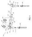
- FIG. 1is an exploded assembly view of a spinal stabilization device/system, including pedicle screws and associated mounting structures, in accordance with an exemplary embodiment of the present disclosure
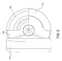
- FIG. 2is a side view (from the left side) of the spinal stabilization device schematically depicted in FIG. 1 according to an exemplary embodiment of the present disclosure
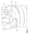
- FIG. 3is a side view of a portion of the spinal stabilization device of FIGS. 1 and 2 showing interaction between an exemplary weld cap and associated structural members;
- FIG. 4is a further side view of a portion of the exemplary spinal stabilization device schematically depicted in the foregoing figures;
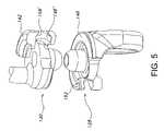
- FIG. 5is a side view of an exemplary spinal stabilization device, with parts removed for clarity;
- FIG. 6is a perspective view of an exemplary spinal stabilization device that schematically depicts welding of a weld cap with respect to an underlying structural member according to the present disclosure
- FIG. 7is a perspective view of an assembled spinal stabilization device/system according to an exemplary embodiment of the present disclosure.
- FIG. 8is a top perspective view of a portion of the exemplary spinal stabilization device/system of FIG. 7 .
- the present disclosureprovides advantageous devices, systems and methods for improving the reliability, dependability and/or durability of spinal stabilization systems. More particularly, the present disclosure provides advantageous devices, systems and methods for mechanically mounting resilient elements (e.g., torsion springs and/or coil springs) to, and/or for coupling resilient elements between, structural members (e.g., plates, caps, flanges, rods, and/or bars) associated with dynamic spinal stabilization systems.
- resilient elementse.g., torsion springs and/or coil springs
- structural memberse.g., plates, caps, flanges, rods, and/or bars
- the mounting and/or coupling methods/techniques of the present disclosureprovide enhanced reliability, dependability and/or durability without significantly increasing material weight or volume requirements and without compromising the important functions of the dynamic spinal stabilization devices/systems of which they form a part.
- the exemplary embodiments disclosed hereinare illustrative of the advantageous spinal stabilization devices/systems and surgical implants of the present disclosure, and of methods/techniques for implementation thereof. It should be understood, however, that the disclosed embodiments are merely exemplary of the present invention, which may be embodied in various forms. Therefore, the details disclosed herein with reference to exemplary dynamic spinal stabilization systems and associated methods/techniques of assembly and use are not to be interpreted as limiting, but merely as the basis for teaching one skilled in the art how to make and use the advantageous dynamic spinal stabilization systems and alternative surgical implants of the present disclosure.
- the dynamic stabilization system 100includes a dynamic stabilization device 126 that includes two structural elements in the form of a first spring cap 128 and a second spring cap 130 , and two resilient elements in the form of an inner spring 132 and an outer spring 134 .
- the first spring cap 128is affixed to an attachment member 102 that is configured to be coupled to the head of a pedicle screw 106 , preferably via a dynamic joint 110 .
- the second spring cap 130is affixed to a rod 118 that is configured to be attached to another attachment member 104 that is in turn coupled to the head of another pedicle screw 108 , preferably via another dynamic joint 112 .
- the dynamic stabilization system 100and particularly the dynamic stabilization device 126 , permits limited degrees of relative axial/longitudinal motion as well as angular/rotational motion.
- the inner spring 132consists of a plurality of coils sharing a common diameter and arranged sequentially about a common axis.
- the outer spring 134also consists of a plurality of coils sharing a common diameter and arranged sequentially about a common axis. In the assembled state, the inner spring 132 is positioned within the outer spring 134 .
- the coil at the end of the inner spring 132is positioned on or around post 119 that extends from spring cap 128 , and against the interior end of spring cap 128 so as to occupy (at least in part) an annular channel formed therein.
- a coil at the opposite end of the inner spring 132is positioned on or around post 121 of the spring cap 130 and against the interior end of the spring cap 130 so as to occupy (at least in part) an annular channel formed therein. In this way, the inner spring 132 is effectively captured between the first spring cap 128 and the second spring cap 130 and effectively floats relative to the opposing posts 119 , 121 .
- the spinal stabilization device 126further includes a sheath member 136 and two end clamps 138 .
- the inner resilient element 132 and outer resilient element 134are positioned within the sheath member 136 , and an end clamp 138 secures the sheath member 136 to each of the structural members 128 , 130 .
- a peripheral groove 146may be formed in the structural member, e.g., end cap 128 , to facilitate positioning of end clamp 138 . Once positioned in or adjacent peripheral groove 146 , end clamp 138 is advantageously crimped or swaged into engagement with end cap 128 .
- weld caps 140 and 142function to secure outer resilient element/spring 134 relative to structural members/end caps 128 and 130 , respectively.
- weld cap 140 and end cap 128cooperate to capture the end region 144 of outer spring 134 therebetween, thereby positively securing outer spring 134 with respect to end cap 128 .
- the coil at the end of the outer spring 134is threaded into spring cap 128 .
- helically-shaped grooves 148 , 148 ′are defined in end caps 128 , 130 , respectively.
- FIG. 6schematically depicts welding material 150 interacting with weld cap 142 so as to secure/capture outer spring 134 relative to end cap 130 .
- the outer spring 134is typically shorter than the inner spring 132 , such that as the first spring cap 128 and the second spring cap 130 are brought toward each other (i.e., to permit the outer spring 134 to be mounted on both), the inner spring 132 is placed in compression.
- the degree to which the inner spring 132 is compressedis generally dependent on the difference in length as between the inner and outer springs 132 , 134 .
- the preload compression of the inner spring 132may be controlled and/or adjusted in part through selection of the relative lengths of the inner and outer springs 132 , 134 .
- the mounting of the outer spring 134 with respect to the spring caps 128 , 130generally includes placing the outer spring 134 in tension.
- the overall preload of the dynamic stabilization device 126corresponds to equal and opposite forces experienced by and/or contained within the inner and outer springs 132 , 134 .
- the inner spring 132reaches its free length (i.e., non compressed state) at or about the point at which a patient's movement exceeds a “neutral zone” (as described more completely in the '270 application). Beyond this point, the inner spring 132 is free floating (e.g., on the opposing posts 119 , 121 ), while the outer spring 134 , already in tension, extends in length even further.
- elevated temperaturesin a range of approximately 1000° F. or higher are used to affix the outer spring 134 to the spring cap 128 , 130 by essentially melting such components together.
- the heat-affected zone so producedcan be at least 0.005′′-0.030′′ in axial length, and is located immediately adjacent the weld formed at the end of the outer spring 134 , and along the active region of the outer spring 134 .
- the heat-affected zonecan include a soft or weak point on the coil at which a Rockwell hardness of the material of the outer spring 134 , ordinarily falling within a range of from approximately 46 to approximately 54, dips sharply; e.g., to a value in a range of from approximately 20 to approximately 24.
- geometric/structural modifications to the outer spring 134 and the spring caps 128 , 130together with incorporation of weld caps 140 , 142 into the overall assembly, have been found to advantageously enhance the reliability and durability of dynamic stabilization device 126 .
- Exemplary embodiments of the advantageous geometric/structural modifications to the outer spring 134 and spring caps 128 , 130 , as well as the incorporation of weld caps 140 , 142are described hereinbelow with reference to FIGS. 2-7 .
- a durability standard of 10,000,000+ failure-free cyclesis believed to be achievable on a sustained and reliable basis.
- the geometric/structural modificationsinclude the creation of a substantial physical separation of the active portion of the outer spring from the heat-affected zone associated with the E-beam welding process, and/or from the actual site of the weld formed between the attached components.
- this separationto the extent that any region of the outer spring becomes significantly annealed, and/or is brought to a significantly lowered Rockwell hardness value as a result of E-beam welding, the amount of cyclic stress to which that softened or annealed portion is exposed is substantially reduced and/or brought to such a low level that the respective junctions between the outer spring and its associated spring caps can exhibit very high levels of reliability/durability.
- the exemplary dynamic stabilization system 100includes attachment members 102 , 104 , pedicle screws 106 , 108 , ball/spherical elements 110 , 112 , and set screws 114 , 116 .
- the attachment member 102is configured to receive the ball/spherical element 110 .
- the ball/spherical element 110then receives the head of the pedicle screw 106 such that a global/dynamic joint is formed between the attachment member 102 and the head of the pedicle screw 106 .
- the set screw 114is then inserted into the head of the pedicle screw 106 , thereby securing the head of the pedicle screw 106 within the ball/spherical element 110 .
- the attachment member 104is configured to receive the ball/spherical element 112 .
- the ball/spherical element 112then receives the head of the pedicle screw 108 such that a global/dynamic joint is formed between the attachment member 104 and the head of the pedicle screw 108 .
- the set screw 116is then inserted into the head of the pedicle screw 108 , thereby securing the head of the pedicle screw 108 within the ball/spherical element 112 .
- the spinal stabilization system 100also includes rod 118 .
- the rodis configured to be inserted into the attachment member 104 , which includes a transverse aperture 120 to accommodate the rod 118 , and a set screw 122 to secure the rod 118 at a desired position within the transverse aperture 120 , e.g., employing a hex driver (not shown).
- Dynamic stabilization element 126includes structural members 128 , 130 , an inner resilient element 132 , an outer resilient element 134 , a sheath member 136 , and two end clamps 138 .
- the structural member 128is affixed to (e.g., is of unitary construction with) the attachment member 102 and takes the form of a plate having multiple features permitting the structural member 128 to function in the manner of an end cap or spring cap with respect to the inner and outer resilient elements 132 , 134 .
- the structural member 130is affixed to (e.g., is of unitary construction with) the rod 118 (which is positioned off-axis or off-center with respect to the structural member 130 ), and takes the form of a plate having multiple features permitting the structural member 130 to function in the manner of an end cap or spring cap with respect to the inner and outer resilient elements 132 , 134 .
- the outer resilient element 134consists of a plurality of coils sharing a common diameter and arranged sequentially about a common axis between a coil termination 180 at an end of the outer resilient element 134 and a coil termination (not shown) at an opposite end thereof. Extending from the coil termination 180 , and substantially continuous therewith, is a bend region 188 of the outer resilient element 134 . According to exemplary embodiments of the present disclosure, a corresponding coil termination and bend region are defined at the opposite end of the outer resilient element 134 . As shown in FIG. 4 , weld cap 140 advantageously includes a substantially arcuate geometry 141 to track the bend region 188 of spring 134 .
- the bend regions, e.g., bend region 188 , of the outer resilient element/spring 134extend peripherally from the respective coil terminations, e.g., coil termination 180 , along respective paths which, when viewed axially from either end of the outer resilient element/spring 134 , are defined by respective single radii that extend from the common axis of the coils of the outer resilient element 134 and that have extents approximately half that of the common diameter of the coils.
- the bend regions, e.g., bend region 188 , of the outer resilient element/spring 134remain within the same peripheral outline defined by the coils of the outer resilient element 134 .
- bend region 188 of the outer resilient element 134is seen to depart from the helical path defined by the coils.
- the bend region 188when viewed from the side as in FIG. 4 , is seen to include a curve or bend in the path of extension of the bend region 188 , according to which the material of the outer resilient element/spring 134 : (1) initially curves away from the adjacent coil at the coil termination 180 ; (2) reaches an apex representing a point of maximum departure from the adjacent coil; and (3) curves therefrom back toward the adjacent coil to return to the helical path defined by the coils.
- the inner resilient element 132is positioned within the outer resilient element 134 , between the respective posts 119 , 121 , and within the respective annular channels of the structural elements 128 , 130 .
- the bend region 188 and the coil at the end of the outer resilient element 134are threaded into the interior end of the structural element 130 until the bend region 188 has substantially passed into or through an aperture formed in the structural element 130 (see, e.g., aperture 192 defined in structural member 128 , as shown in FIG. 5 ) and the bend region termination has been caused to drop or snap into place within a notch formed in the exterior end of the structural element 130 .
- exemplary weld caps 140 , 142define a geometry that includes a variable height/thickness. More particularly, a reduced height/thickness region 152 is defined radially inward of a greater height/thickness region 154 . An arcuate transition region 156 is generally provided to transition between regions 152 and 154 .
- the reduced height/thickness region 152advantageously provides an effective geometry for welding of the weld caps 140 , 142 relative to the underlying structural members, i.e., end caps 128 , 130 .
- the weld material 150typically interacts with the weld cap in the reduced height/thickness region 152 , defining a generally sloped and/or arcuate geometry relative to the axis of the spinal stabilization device 126 .
- the greater height/thickness region 154in turn provides sufficient material to ensure effective compression/capture of outer spring 134 .
- helical channels 158 , 158 ′are defined in the undersurface of region 154 of weld caps 140 , 142 to facilitate alignment and capture of the end region (e.g., end region 188 ) of outer spring 134 .
- Weld caps 140 , 142are generally fabricated from an appropriate metal, e.g., cobalt chrome, titanium, stainless steel or the like.
- the circumferential/angular extent of weld caps 140 , 142is generally selected to ensure sufficient clamping/compressive force is exerted on outer spring 134 , e.g., to ensure that the end region of the outer spring is without freedom of movement in any axis, e.g., axial, rotational or a combination thereof.
- surface treatment(s)may be undertaken to increase/enhance the gripping forces associated with the weld cap and/or opposed grove/channel surfaces associated with the corresponding end cap.
- surfaces 148 ′ and 158 ′may be advantageously grip blasted to increase the frictional forces imparted thereby when clamped/compressed into engagement with a resilient member, e.g., spring 134 .
- Alternative surface treatment modalitiesmay also be employed, e.g., sand blasting, abrasive blasting, surface etching and the like, as will be apparent to persons skilled in the art.
- weld caps 140 , 142each define a circumferential/angular extent of about 90° to about 160°, although geometries outside the noted range are contemplated based on the overall design of the spinal stabilization device/system and the forces to be encountered thereby.
- Exemplary heights in region 154are between about 0.45 inches and 0.55 inches, while exemplary heights in region 152 are between 30% and 60% of the height of region 154 .
- the geometry of weld caps 140 , 142 in region 152may be substantially planar or non-planar, provided adequate surface geometry is provided to accommodate and effect a desired welding operation.
- components that define the spinal stabilization device 126i.e., inner spring 132 , outer spring 134 , and end caps 128 , 130 , are combined to define a sub-assembly.
- Weld caps 140 , 142are positioned with respect to the sub-assembly such that the end regions of the outer spring 134 are aligned with the channels/grooves 158 , 158 ′ formed in the underside of the weld caps, and the sub-assembly is then generally fixtured so as to place the weld cap/end cap region in compression.
- a minimal clearancemay exist between the weld flange 154 and the corresponding end caps 128 , 130 , e.g., about 0.0005 to about 0.003 inches, prior to application of the fixturing compression.
- a welding operationis generally initiated such that welding material 150 is applied to the weld cap/end cap interface as schematically depicted in FIG. 6 , thereby securing the weld caps 140 , 142 with respect to the corresponding end caps 128 , 130 and locking outer spring 134 therebetween.
- the disclosed assembly techniqueadvantageously maintains a distance or spacing between the welding heat effects and the outer spring 134 , such that undesirable annealing effects are avoided in the active region of the outer spring 134 .
- the disclosed system design and assembly techniqueprovides an efficient, reliable and effective approach to ensuring product integrity while avoiding any deleterious effects on the disclosed dynamic/spring system.
- exemplary embodiments of the present disclosurefurther contemplate incorporation of a sheath assembly 160 over or concentrically around the spring members 132 , 134 .
- Sheath assembly 160generally includes sheath member 136 and end clamps 138 .
- exemplary end clamps 138include circumferentially spaced notches 162 that facilitate interaction between the end clamps 138 and the sheath member 136 , and further facilitate assembly of the sheath assembly 160 with respect to the underlying end cap 128 .
- the weld material 150has been omitted for clarity purposes.
- the dynamic stabilization device 126 associated with the spinal stabilization system 100 described hereinaboveprovides numerous advantages. For example, improved reliability and durability may be achieved with the disclosed dynamic stabilization device based at least in part on the fact that the heat-affected zone associated with the process of securing the outer resilient element 134 with respect to the structural elements 128 , 130 via welding and use of weld caps 140 , 142 is physically separated from the active region of the outer resilient element 134 , and is therefore isolated from the cyclical stress associated with repeated extension/contraction and/or bending during normal use and/or representative mechanical testing.
- the dynamic stabilization device 126 associated with the spinal stabilization system 100 described hereinabovecan be the subject of numerous modifications and variations while still exhibiting the above-discussed advantages over other dynamic junctions for spinal stabilization systems.
- the rod 118can be repositioned to an axial position with respect to the structural member 130 .
- the weld caps 140 , 142can be affixed to the structural members 128 , 130 by other welding processes than E-beam welding, and/or by one or more non-welding means of attachment, such as by clamping or the use of mechanical fasteners appropriate for use in conjunction with small gage springs, by an adhesive-based process, or via the use of a single mold to form the two components together as a single piece.
- attachment regionsare similarly disposed physically separately relative to the respective active region of the outer resilient element 134 (whether or not heat-affected zones are present), and are thereby similarly shielded from the types and levels of cyclical stress known to produce fatigue failure.
- the outer resilient element 134need not necessarily be configured in the manner of a coil spring, but may instead take the form of one or more other types of resilient elements, such as a leaf spring, a torsion spring or bar, etc. Additionally, the outer resilient element 134 may be employed in a dynamic junction that does not also include the inner resilient element 132 . Many other variations and/or modifications are possible.
Landscapes
- Health & Medical Sciences (AREA)
- Orthopedic Medicine & Surgery (AREA)
- Surgery (AREA)
- Neurology (AREA)
- Life Sciences & Earth Sciences (AREA)
- Engineering & Computer Science (AREA)
- Biomedical Technology (AREA)
- Nuclear Medicine, Radiotherapy & Molecular Imaging (AREA)
- Heart & Thoracic Surgery (AREA)
- Medical Informatics (AREA)
- Molecular Biology (AREA)
- Animal Behavior & Ethology (AREA)
- General Health & Medical Sciences (AREA)
- Public Health (AREA)
- Veterinary Medicine (AREA)
- Mechanical Engineering (AREA)
- Surgical Instruments (AREA)
- Prostheses (AREA)
Abstract
Description
- Exemplary embodiments of the spring junction (and associated spring/structural member subassembly) are capable of undergoing at least approximately 10,000,000 cycles of combined extension/contraction and bending (e.g., during mechanical testing);
- Implementation of the disclosed spring junctions have no substantial effect on the footprint of the dynamic stabilization devices in which they are incorporated, e.g., the resilient elements (e.g., springs) of such spinal stabilization devices do not extend radially inwardly/outwardly or linearly to a greater extent than the dynamic stabilization devices that do not include the disclosed spring junctions, thereby preserving compatibility with existing components and/or proven or preferred geometries;
- An outwardly/upwardly, then inwardly/downwardly extending bend region at each end of the resilient element, combined with channels or grooves formed in the weld cap/structural member provide an alignment which positively locates the ends of the resilient element within their respective channels/grooves during pre-welding assembly, without undue risk of annealing and/or other types of damage to the active region of the resilient element.
- In addition, the noted geometric aspects of the bend region advantageously facilitate and/or enhance the mechanical integrity of the junction between the resilient element and the associated channels/grooves. Of note, a bend region having the noted geometric characteristics has reduced freedom of movement relative to the associated channels/grooves, e.g., in terms of rotation around the axis of the resilient element in the region of the junction.
Claims (16)
Priority Applications (2)
| Application Number | Priority Date | Filing Date | Title |
|---|---|---|---|
| US11/405,196US7699875B2 (en) | 2006-04-17 | 2006-04-17 | Spinal stabilization device with weld cap |
| PCT/US2006/029713WO2007019110A2 (en) | 2005-08-03 | 2006-07-27 | Spring junction and assembly methods for spinal device |
Applications Claiming Priority (1)
| Application Number | Priority Date | Filing Date | Title |
|---|---|---|---|
| US11/405,196US7699875B2 (en) | 2006-04-17 | 2006-04-17 | Spinal stabilization device with weld cap |
Publications (2)
| Publication Number | Publication Date |
|---|---|
| US20070244481A1 US20070244481A1 (en) | 2007-10-18 |
| US7699875B2true US7699875B2 (en) | 2010-04-20 |
Family
ID=38605779
Family Applications (1)
| Application Number | Title | Priority Date | Filing Date |
|---|---|---|---|
| US11/405,196Expired - Fee RelatedUS7699875B2 (en) | 2005-08-03 | 2006-04-17 | Spinal stabilization device with weld cap |
Country Status (1)
| Country | Link |
|---|---|
| US (1) | US7699875B2 (en) |
Cited By (71)
| Publication number | Priority date | Publication date | Assignee | Title |
|---|---|---|---|---|
| US20050033432A1 (en)* | 2003-08-05 | 2005-02-10 | Charles Gordon | Artificial spinal unit assemblies |
| US20070043356A1 (en)* | 2005-07-26 | 2007-02-22 | Timm Jens P | Dynamic spine stabilization device with travel-limiting functionality |
| US20070191955A1 (en)* | 2003-12-08 | 2007-08-16 | St. Francis Medical Technologies, Inc. | System and Method for Replacing Degenerated Spinal Disks |
| US20080306532A1 (en)* | 2007-06-05 | 2008-12-11 | Spartek Medical, Inc. | Deflection rod system dimensioned for deflection to a load characteristic for dynamic stabilization and motion preservation spinal implantation system and method |
| US20100228298A1 (en)* | 2007-08-17 | 2010-09-09 | Jmea Corporation | Method For Treating A Spinal Deformity |
| US20100331985A1 (en)* | 2003-08-05 | 2010-12-30 | Flexuspine, Inc. | Expandable intervertebral implant system and method |
| US7959677B2 (en) | 2007-01-19 | 2011-06-14 | Flexuspine, Inc. | Artificial functional spinal unit system and method for use |
| US8007518B2 (en) | 2008-02-26 | 2011-08-30 | Spartek Medical, Inc. | Load-sharing component having a deflectable post and method for dynamic stabilization of the spine |
| US8012181B2 (en) | 2008-02-26 | 2011-09-06 | Spartek Medical, Inc. | Modular in-line deflection rod and bone anchor system and method for dynamic stabilization of the spine |
| US8016861B2 (en) | 2008-02-26 | 2011-09-13 | Spartek Medical, Inc. | Versatile polyaxial connector assembly and method for dynamic stabilization of the spine |
| US8021396B2 (en) | 2007-06-05 | 2011-09-20 | Spartek Medical, Inc. | Configurable dynamic spinal rod and method for dynamic stabilization of the spine |
| US8043340B1 (en)* | 2008-06-09 | 2011-10-25 | Melvin Law | Dynamic spinal stabilization system |
| US8048115B2 (en) | 2007-06-05 | 2011-11-01 | Spartek Medical, Inc. | Surgical tool and method for implantation of a dynamic bone anchor |
| US8052723B2 (en) | 2003-08-05 | 2011-11-08 | Flexuspine Inc. | Dynamic posterior stabilization systems and methods of use |
| US8057515B2 (en) | 2008-02-26 | 2011-11-15 | Spartek Medical, Inc. | Load-sharing anchor having a deflectable post and centering spring and method for dynamic stabilization of the spine |
| US8083775B2 (en) | 2008-02-26 | 2011-12-27 | Spartek Medical, Inc. | Load-sharing bone anchor having a natural center of rotation and method for dynamic stabilization of the spine |
| US8083772B2 (en) | 2007-06-05 | 2011-12-27 | Spartek Medical, Inc. | Dynamic spinal rod assembly and method for dynamic stabilization of the spine |
| US8092501B2 (en) | 2007-06-05 | 2012-01-10 | Spartek Medical, Inc. | Dynamic spinal rod and method for dynamic stabilization of the spine |
| US8096996B2 (en) | 2007-03-20 | 2012-01-17 | Exactech, Inc. | Rod reducer |
| US8097024B2 (en) | 2008-02-26 | 2012-01-17 | Spartek Medical, Inc. | Load-sharing bone anchor having a deflectable post and method for stabilization of the spine |
| US8105359B2 (en)* | 2007-06-05 | 2012-01-31 | Spartek Medical, Inc. | Deflection rod system for a dynamic stabilization and motion preservation spinal implantation system and method |
| US8114134B2 (en) | 2007-06-05 | 2012-02-14 | Spartek Medical, Inc. | Spinal prosthesis having a three bar linkage for motion preservation and dynamic stabilization of the spine |
| US8118869B2 (en) | 2006-03-08 | 2012-02-21 | Flexuspine, Inc. | Dynamic interbody device |
| US8157844B2 (en) | 2007-10-22 | 2012-04-17 | Flexuspine, Inc. | Dampener system for a posterior stabilization system with a variable length elongated member |
| US8162994B2 (en) | 2007-10-22 | 2012-04-24 | Flexuspine, Inc. | Posterior stabilization system with isolated, dual dampener systems |
| US8182514B2 (en) | 2007-10-22 | 2012-05-22 | Flexuspine, Inc. | Dampener system for a posterior stabilization system with a fixed length elongated member |
| US8187330B2 (en) | 2007-10-22 | 2012-05-29 | Flexuspine, Inc. | Dampener system for a posterior stabilization system with a variable length elongated member |
| US8211155B2 (en) | 2008-02-26 | 2012-07-03 | Spartek Medical, Inc. | Load-sharing bone anchor having a durable compliant member and method for dynamic stabilization of the spine |
| US8226690B2 (en) | 2005-07-22 | 2012-07-24 | The Board Of Trustees Of The Leland Stanford Junior University | Systems and methods for stabilization of bone structures |
| US8257397B2 (en) | 2009-12-02 | 2012-09-04 | Spartek Medical, Inc. | Low profile spinal prosthesis incorporating a bone anchor having a deflectable post and a compound spinal rod |
| US8267969B2 (en) | 2004-10-20 | 2012-09-18 | Exactech, Inc. | Screw systems and methods for use in stabilization of bone structures |
| US8267979B2 (en) | 2008-02-26 | 2012-09-18 | Spartek Medical, Inc. | Load-sharing bone anchor having a deflectable post and axial spring and method for dynamic stabilization of the spine |
| US8267965B2 (en) | 2007-10-22 | 2012-09-18 | Flexuspine, Inc. | Spinal stabilization systems with dynamic interbody devices |
| US20120253404A1 (en)* | 2003-05-02 | 2012-10-04 | Rachiotek, Llc | Method for stabilizing a spinal segment |
| US8317836B2 (en) | 2007-06-05 | 2012-11-27 | Spartek Medical, Inc. | Bone anchor for receiving a rod for stabilization and motion preservation spinal implantation system and method |
| US8333792B2 (en) | 2008-02-26 | 2012-12-18 | Spartek Medical, Inc. | Load-sharing bone anchor having a deflectable post and method for dynamic stabilization of the spine |
| US8337536B2 (en) | 2008-02-26 | 2012-12-25 | Spartek Medical, Inc. | Load-sharing bone anchor having a deflectable post with a compliant ring and method for stabilization of the spine |
| US8377067B2 (en) | 2004-02-27 | 2013-02-19 | Roger P. Jackson | Orthopedic implant rod reduction tool set and method |
| US8394133B2 (en) | 2004-02-27 | 2013-03-12 | Roger P. Jackson | Dynamic fixation assemblies with inner core and outer coil-like member |
| US8430916B1 (en) | 2012-02-07 | 2013-04-30 | Spartek Medical, Inc. | Spinal rod connectors, methods of use, and spinal prosthesis incorporating spinal rod connectors |
| US8444681B2 (en) | 2009-06-15 | 2013-05-21 | Roger P. Jackson | Polyaxial bone anchor with pop-on shank, friction fit retainer and winged insert |
| US8518085B2 (en) | 2010-06-10 | 2013-08-27 | Spartek Medical, Inc. | Adaptive spinal rod and methods for stabilization of the spine |
| US8523865B2 (en) | 2005-07-22 | 2013-09-03 | Exactech, Inc. | Tissue splitter |
| US8523912B2 (en) | 2007-10-22 | 2013-09-03 | Flexuspine, Inc. | Posterior stabilization systems with shared, dual dampener systems |
| US8556938B2 (en) | 2009-06-15 | 2013-10-15 | Roger P. Jackson | Polyaxial bone anchor with non-pivotable retainer and pop-on shank, some with friction fit |
| US8784453B1 (en) | 2008-06-09 | 2014-07-22 | Melvin Law | Dynamic spinal stabilization system |
| US8814911B2 (en) | 2003-06-18 | 2014-08-26 | Roger P. Jackson | Polyaxial bone screw with cam connection and lock and release insert |
| US8894657B2 (en) | 2004-02-27 | 2014-11-25 | Roger P. Jackson | Tool system for dynamic spinal implants |
| US8911479B2 (en) | 2012-01-10 | 2014-12-16 | Roger P. Jackson | Multi-start closures for open implants |
| US8940051B2 (en) | 2011-03-25 | 2015-01-27 | Flexuspine, Inc. | Interbody device insertion systems and methods |
| US8998959B2 (en) | 2009-06-15 | 2015-04-07 | Roger P Jackson | Polyaxial bone anchors with pop-on shank, fully constrained friction fit retainer and lock and release insert |
| US9050139B2 (en) | 2004-02-27 | 2015-06-09 | Roger P. Jackson | Orthopedic implant rod reduction tool set and method |
| US9168069B2 (en) | 2009-06-15 | 2015-10-27 | Roger P. Jackson | Polyaxial bone anchor with pop-on shank and winged insert with lower skirt for engaging a friction fit retainer |
| US9216039B2 (en) | 2004-02-27 | 2015-12-22 | Roger P. Jackson | Dynamic spinal stabilization assemblies, tool set and method |
| US9393047B2 (en) | 2009-06-15 | 2016-07-19 | Roger P. Jackson | Polyaxial bone anchor with pop-on shank and friction fit retainer with low profile edge lock |
| US9480517B2 (en) | 2009-06-15 | 2016-11-01 | Roger P. Jackson | Polyaxial bone anchor with pop-on shank, shank, friction fit retainer, winged insert and low profile edge lock |
| US9492288B2 (en) | 2013-02-20 | 2016-11-15 | Flexuspine, Inc. | Expandable fusion device for positioning between adjacent vertebral bodies |
| US9517144B2 (en) | 2014-04-24 | 2016-12-13 | Exactech, Inc. | Limited profile intervertebral implant with incorporated fastening mechanism |
| US9526627B2 (en) | 2011-11-17 | 2016-12-27 | Exactech, Inc. | Expandable interbody device system and method |
| US9629669B2 (en) | 2004-11-23 | 2017-04-25 | Roger P. Jackson | Spinal fixation tool set and method |
| US9743957B2 (en) | 2004-11-10 | 2017-08-29 | Roger P. Jackson | Polyaxial bone screw with shank articulation pressure insert and method |
| US9907574B2 (en) | 2008-08-01 | 2018-03-06 | Roger P. Jackson | Polyaxial bone anchors with pop-on shank, friction fit fully restrained retainer, insert and tool receiving features |
| US9980753B2 (en) | 2009-06-15 | 2018-05-29 | Roger P Jackson | pivotal anchor with snap-in-place insert having rotation blocking extensions |
| US10039578B2 (en) | 2003-12-16 | 2018-08-07 | DePuy Synthes Products, Inc. | Methods and devices for minimally invasive spinal fixation element placement |
| US10039577B2 (en) | 2004-11-23 | 2018-08-07 | Roger P Jackson | Bone anchor receiver with horizontal radiused tool attachment structures and parallel planar outer surfaces |
| US10194951B2 (en) | 2005-05-10 | 2019-02-05 | Roger P. Jackson | Polyaxial bone anchor with compound articulation and pop-on shank |
| US10299839B2 (en) | 2003-12-16 | 2019-05-28 | Medos International Sárl | Percutaneous access devices and bone anchor assemblies |
| US10363070B2 (en) | 2009-06-15 | 2019-07-30 | Roger P. Jackson | Pivotal bone anchor assemblies with pressure inserts and snap on articulating retainers |
| US10398565B2 (en) | 2014-04-24 | 2019-09-03 | Choice Spine, Llc | Limited profile intervertebral implant with incorporated fastening and locking mechanism |
| US11419642B2 (en) | 2003-12-16 | 2022-08-23 | Medos International Sarl | Percutaneous access devices and bone anchor assemblies |
| US12383311B2 (en) | 2010-05-14 | 2025-08-12 | Roger P. Jackson | Pivotal bone anchor assembly and method for use thereof |
Families Citing this family (24)
| Publication number | Priority date | Publication date | Assignee | Title |
|---|---|---|---|---|
| US7833250B2 (en) | 2004-11-10 | 2010-11-16 | Jackson Roger P | Polyaxial bone screw with helically wound capture connection |
| US8876868B2 (en) | 2002-09-06 | 2014-11-04 | Roger P. Jackson | Helical guide and advancement flange with radially loaded lip |
| US7377923B2 (en) | 2003-05-22 | 2008-05-27 | Alphatec Spine, Inc. | Variable angle spinal screw assembly |
| US8926670B2 (en) | 2003-06-18 | 2015-01-06 | Roger P. Jackson | Polyaxial bone screw assembly |
| US7967850B2 (en) | 2003-06-18 | 2011-06-28 | Jackson Roger P | Polyaxial bone anchor with helical capture connection, insert and dual locking assembly |
| US8366753B2 (en) | 2003-06-18 | 2013-02-05 | Jackson Roger P | Polyaxial bone screw assembly with fixed retaining structure |
| US11241261B2 (en) | 2005-09-30 | 2022-02-08 | Roger P Jackson | Apparatus and method for soft spinal stabilization using a tensionable cord and releasable end structure |
| US7651502B2 (en) | 2004-09-24 | 2010-01-26 | Jackson Roger P | Spinal fixation tool set and method for rod reduction and fastener insertion |
| US8926672B2 (en) | 2004-11-10 | 2015-01-06 | Roger P. Jackson | Splay control closure for open bone anchor |
| WO2006057837A1 (en) | 2004-11-23 | 2006-06-01 | Jackson Roger P | Spinal fixation tool attachment structure |
| US7901437B2 (en) | 2007-01-26 | 2011-03-08 | Jackson Roger P | Dynamic stabilization member with molded connection |
| US20080058808A1 (en) | 2006-06-14 | 2008-03-06 | Spartek Medical, Inc. | Implant system and method to treat degenerative disorders of the spine |
| DE602008004213D1 (en)* | 2008-05-06 | 2011-02-10 | Biedermann Motech Gmbh | Rod-shaped implant, in particular for the dynamic stabilization of the spine |
| US9668771B2 (en) | 2009-06-15 | 2017-06-06 | Roger P Jackson | Soft stabilization assemblies with off-set connector |
| US11229457B2 (en) | 2009-06-15 | 2022-01-25 | Roger P. Jackson | Pivotal bone anchor assembly with insert tool deployment |
| US8911478B2 (en) | 2012-11-21 | 2014-12-16 | Roger P. Jackson | Splay control closure for open bone anchor |
| US10058354B2 (en) | 2013-01-28 | 2018-08-28 | Roger P. Jackson | Pivotal bone anchor assembly with frictional shank head seating surfaces |
| US8852239B2 (en) | 2013-02-15 | 2014-10-07 | Roger P Jackson | Sagittal angle screw with integral shank and receiver |
| US9775650B2 (en)* | 2013-03-11 | 2017-10-03 | Dynamic Spine, Llc | Screw clamp orthopedic device and methods of implementation |
| US9566092B2 (en) | 2013-10-29 | 2017-02-14 | Roger P. Jackson | Cervical bone anchor with collet retainer and outer locking sleeve |
| US9717533B2 (en) | 2013-12-12 | 2017-08-01 | Roger P. Jackson | Bone anchor closure pivot-splay control flange form guide and advancement structure |
| US9451993B2 (en) | 2014-01-09 | 2016-09-27 | Roger P. Jackson | Bi-radial pop-on cervical bone anchor |
| US9597119B2 (en) | 2014-06-04 | 2017-03-21 | Roger P. Jackson | Polyaxial bone anchor with polymer sleeve |
| US10064658B2 (en) | 2014-06-04 | 2018-09-04 | Roger P. Jackson | Polyaxial bone anchor with insert guides |
Citations (67)
| Publication number | Priority date | Publication date | Assignee | Title |
|---|---|---|---|---|
| US2733596A (en) | 1956-02-07 | Measurement of dynamic modulus of | ||
| US4328960A (en) | 1978-02-16 | 1982-05-11 | Fichtel & Sachs Ag | Fluid damping unit featuring combined fluidic and spring damping characteristics |
| US4352514A (en) | 1977-12-21 | 1982-10-05 | Firster Corporation Limited | Shock absorbing device |
| US4558852A (en) | 1982-03-11 | 1985-12-17 | Sig Schweizerische Industrie-Gesellschaft | Vibration damper with linearly reciprocating mass |
| US4743260A (en) | 1985-06-10 | 1988-05-10 | Burton Charles V | Method for a flexible stabilization system for a vertebral column |
| US4759769A (en) | 1987-02-12 | 1988-07-26 | Health & Research Services Inc. | Artificial spinal disc |
| US5034011A (en) | 1990-08-09 | 1991-07-23 | Advanced Spine Fixation Systems Incorporated | Segmental instrumentation of the posterior spine |
| US5071264A (en)* | 1969-11-28 | 1991-12-10 | Franke & Heydrich Kg | Rolling bearing |
| EP0516567A1 (en) | 1991-05-30 | 1992-12-02 | Société dite: "PSI" | Shock-absorbing device for intervertebral stabilisation |
| US5174551A (en) | 1990-06-20 | 1992-12-29 | Stabilus Gmbh | Cylinder piston device |
| US5180393A (en) | 1990-09-21 | 1993-01-19 | Polyclinique De Bourgogne & Les Hortensiad | Artificial ligament for the spine |
| FR2681520A1 (en) | 1991-09-24 | 1993-03-26 | Graf Henry | DEVICE FOR MEASURING AMPLITUDES OF TWO VERTEBRATES IN THREE ORTHOGONAL PLANS. |
| US5237787A (en)* | 1990-08-10 | 1993-08-24 | Geilinger Ag | Glazing element |
| FR2692468A1 (en) | 1992-06-19 | 1993-12-24 | Grae Henry | Spreading and spacing instrument for surgery on vertebrae - has series of tubular shafts, each attached to implant screwed into vertebra, for positioning flexible plastics sheet spreading muscle tissue |
| EP0576379A1 (en) | 1992-06-25 | 1993-12-29 | Psi | Use of dampers with improved damping at the end of stroke in a device for intervertebral stabilisation |
| FR2694182A1 (en) | 1992-07-31 | 1994-02-04 | Psi | Fastening for interpedicular vertebral prosthesis components - comprises bone-implanted shafts, with spherical heads engaged over upper portions for cooperation with prosthesis-attached rings |
| EP0611554A1 (en) | 1993-02-17 | 1994-08-24 | Psi | Extradiscal intravertebral prosthesis for the control of intervertebral distance variations by means of a double damper |
| FR2701651A1 (en) | 1993-02-17 | 1994-08-26 | Psi | Double shock-absorber for intervertebral stabilisation |
| US5415661A (en) | 1993-03-24 | 1995-05-16 | University Of Miami | Implantable spinal assist device |
| CA2135838A1 (en) | 1993-11-18 | 1995-05-19 | Henry Graf | Extra-discal intervertebral prosthesis |
| US5423816A (en) | 1993-07-29 | 1995-06-13 | Lin; Chih I. | Intervertebral locking device |
| US5501684A (en) | 1992-06-25 | 1996-03-26 | Synthes (U.S.A.) | Osteosynthetic fixation device |
| US5505118A (en) | 1991-09-16 | 1996-04-09 | Forsvarets Forskningsinstitutt | Gun barrel vibration damper |
| US5653680A (en) | 1995-08-10 | 1997-08-05 | Cruz; Mark K. | Active wrist brace |
| US5672175A (en) | 1993-08-27 | 1997-09-30 | Martin; Jean Raymond | Dynamic implanted spinal orthosis and operative procedure for fitting |
| CA2213058A1 (en) | 1996-08-01 | 1998-02-01 | Henry Graf | Device for binding together and mechanically assisting the vertebra |
| JPH10277070A (en) | 1997-04-09 | 1998-10-20 | Shigeo Sano | Artificial intervertebral joint |
| USRE36221E (en) | 1989-02-03 | 1999-06-01 | Breard; Francis Henri | Flexible inter-vertebral stabilizer as well as process and apparatus for determining or verifying its tension before installation on the spinal column |
| FR2772594A1 (en) | 1997-12-19 | 1999-06-25 | Henry Graf | Partial posterior intervertebral disc prosthesis |
| FR2794362A1 (en) | 1999-06-02 | 2000-12-08 | Henry Graf | INTERVERTEBRAL IMPLANT AND INSTALLATION ASSEMBLY OF SUCH AN IMPLANT |
| US6162223A (en) | 1999-04-09 | 2000-12-19 | Smith & Nephew, Inc. | Dynamic wrist fixation apparatus for early joint motion in distal radius fractures |
| US6176860B1 (en) | 1995-07-24 | 2001-01-23 | Hadasit Medical Research Services & Development Company, Ltd. | Orthopaedic fixator |
| FR2799949A1 (en) | 1999-10-22 | 2001-04-27 | Abder Benazza | Spinal osteosynthesis apparatus has lengthwise supports in form of single or double spiral springs to allow for movement |
| US6241730B1 (en) | 1997-11-26 | 2001-06-05 | Scient'x (Societe A Responsabilite Limitee) | Intervertebral link device capable of axial and angular displacement |
| WO2001039678A1 (en) | 1999-12-01 | 2001-06-07 | Henry Graf | Intervertebral stabilising device |
| FR2801782A1 (en) | 1999-12-01 | 2001-06-08 | Henry Graf | Intervertebral stabiliser comprises implant between adjacent vertebrae and movement damper to rear of spine |
| WO2001045576A1 (en) | 1999-12-20 | 2001-06-28 | Synthes Ag Chur | Device for the stabilisation of two adjacent verterbral bodies of the spine |
| FR2803188A1 (en) | 1999-12-29 | 2001-07-06 | Henry Graf | DEVICE AND INTERVERTEBRAL STABILIZATION ASSEMBLY |
| US6267764B1 (en) | 1996-11-15 | 2001-07-31 | Stryker France S.A. | Osteosynthesis system with elastic deformation for spinal column |
| US6293949B1 (en) | 2000-03-01 | 2001-09-25 | Sdgi Holdings, Inc. | Superelastic spinal stabilization system and method |
| FR2809304A1 (en) | 2000-05-24 | 2001-11-30 | Henry Graf | Intervertebral stabiliser comprises implant between adjacent vertebrae and movement damper to rear of spine |
| WO2002000124A1 (en) | 2000-06-30 | 2002-01-03 | Sdgi Holdings, Inc. | Intervertebral linking device |
| FR2810873A1 (en) | 2000-06-30 | 2002-01-04 | Henry Graf | Intervertebral coupling for two or more vertebrae has intermediate element between fixed and mobile components to allow movement |
| FR2812535A1 (en) | 2000-08-01 | 2002-02-08 | Henry Graf | Intervertebral coupling for two or more vertebrae has intermediate element between fixed and mobile components to allow movement |
| US6375681B1 (en) | 1998-06-23 | 2002-04-23 | Ebi, L.P. | Vertebral body replacement |
| US6402750B1 (en) | 2000-04-04 | 2002-06-11 | Spinlabs, Llc | Devices and methods for the treatment of spinal disorders |
| US6440169B1 (en) | 1998-02-10 | 2002-08-27 | Dimso | Interspinous stabilizer to be fixed to spinous processes of two vertebrae |
| US20020151978A1 (en) | 1996-07-22 | 2002-10-17 | Fred Zacouto | Skeletal implant |
| WO2002102259A2 (en) | 2001-06-16 | 2002-12-27 | Dilip Kumar Sengupta | An assembly for the stabilisation of vertebral bodies of the spine |
| US6508818B2 (en) | 1998-08-21 | 2003-01-21 | Synthes (U.S.A.) | Bone anchoring assembly with a snap-in ballhead |
| US6554831B1 (en) | 2000-09-01 | 2003-04-29 | Hopital Sainte-Justine | Mobile dynamic system for treating spinal disorder |
| GB2382304A (en) | 2001-10-10 | 2003-05-28 | Dilip Kumar Sengupta | An assembly for soft stabilisation of vertebral bodies of the spine |
| US20030171749A1 (en) | 2000-07-25 | 2003-09-11 | Regis Le Couedic | Semirigid linking piece for stabilizing the spine |
| US6645207B2 (en) | 2000-05-08 | 2003-11-11 | Robert A. Dixon | Method and apparatus for dynamized spinal stabilization |
| US20030220642A1 (en) | 2002-05-21 | 2003-11-27 | Stefan Freudiger | Elastic stabilization system for vertebral columns |
| US20030220643A1 (en) | 2002-05-24 | 2003-11-27 | Ferree Bret A. | Devices to prevent spinal extension |
| US20040049189A1 (en) | 2000-07-25 | 2004-03-11 | Regis Le Couedic | Flexible linking piece for stabilising the spine |
| US20040049190A1 (en) | 2002-08-09 | 2004-03-11 | Biedermann Motech Gmbh | Dynamic stabilization device for bones, in particular for vertebrae |
| US20040082954A1 (en) | 2000-06-23 | 2004-04-29 | Teitelbaum George P. | Formable orthopedic fixation system with cross linking |
| US20040143264A1 (en) | 2002-08-23 | 2004-07-22 | Mcafee Paul C. | Metal-backed UHMWPE rod sleeve system preserving spinal motion |
| US20040147928A1 (en) | 2002-10-30 | 2004-07-29 | Landry Michael E. | Spinal stabilization system using flexible members |
| US20040167523A1 (en) | 2000-12-08 | 2004-08-26 | Jackson Roger P. | Closure for rod receiving orthopedic implant having a pair of spaced apertures for removal |
| US20050171543A1 (en)* | 2003-05-02 | 2005-08-04 | Timm Jens P. | Spine stabilization systems and associated devices, assemblies and methods |
| US20060011243A1 (en)* | 2004-07-14 | 2006-01-19 | Scott Jacobs | Mechanical in line timer valve |
| US20060036240A1 (en) | 2004-08-09 | 2006-02-16 | Innovative Spinal Technologies | System and method for dynamic skeletal stabilization |
| US20060264940A1 (en) | 2003-09-29 | 2006-11-23 | Stephan Hartmann | Dynamic damping element for two bones |
| US20070032123A1 (en)* | 2005-08-03 | 2007-02-08 | Timm Jens P | Spring junction and assembly methods for spinal device |
- 2006
- 2006-04-17USUS11/405,196patent/US7699875B2/ennot_activeExpired - Fee Related
Patent Citations (93)
| Publication number | Priority date | Publication date | Assignee | Title |
|---|---|---|---|---|
| US2733596A (en) | 1956-02-07 | Measurement of dynamic modulus of | ||
| US5071264A (en)* | 1969-11-28 | 1991-12-10 | Franke & Heydrich Kg | Rolling bearing |
| US4352514A (en) | 1977-12-21 | 1982-10-05 | Firster Corporation Limited | Shock absorbing device |
| US4328960A (en) | 1978-02-16 | 1982-05-11 | Fichtel & Sachs Ag | Fluid damping unit featuring combined fluidic and spring damping characteristics |
| US4558852A (en) | 1982-03-11 | 1985-12-17 | Sig Schweizerische Industrie-Gesellschaft | Vibration damper with linearly reciprocating mass |
| US4650167A (en) | 1982-03-11 | 1987-03-17 | Sig Schweizerische Industrie-Gesellschaft | Vibration damper |
| US4743260A (en) | 1985-06-10 | 1988-05-10 | Burton Charles V | Method for a flexible stabilization system for a vertebral column |
| US4759769A (en) | 1987-02-12 | 1988-07-26 | Health & Research Services Inc. | Artificial spinal disc |
| USRE36221E (en) | 1989-02-03 | 1999-06-01 | Breard; Francis Henri | Flexible inter-vertebral stabilizer as well as process and apparatus for determining or verifying its tension before installation on the spinal column |
| US5174551A (en) | 1990-06-20 | 1992-12-29 | Stabilus Gmbh | Cylinder piston device |
| US5034011A (en) | 1990-08-09 | 1991-07-23 | Advanced Spine Fixation Systems Incorporated | Segmental instrumentation of the posterior spine |
| US5237787A (en)* | 1990-08-10 | 1993-08-24 | Geilinger Ag | Glazing element |
| US5180393A (en) | 1990-09-21 | 1993-01-19 | Polyclinique De Bourgogne & Les Hortensiad | Artificial ligament for the spine |
| FR2676911A1 (en) | 1991-05-30 | 1992-12-04 | Psi Ste Civile Particuliere | INTERVERTEBRAL STABILIZATION DEVICE WITH SHOCK ABSORBERS. |
| US5540688A (en) | 1991-05-30 | 1996-07-30 | Societe "Psi" | Intervertebral stabilization device incorporating dampers |
| EP0516567A1 (en) | 1991-05-30 | 1992-12-02 | Société dite: "PSI" | Shock-absorbing device for intervertebral stabilisation |
| US5505118A (en) | 1991-09-16 | 1996-04-09 | Forsvarets Forskningsinstitutt | Gun barrel vibration damper |
| US5291901A (en) | 1991-09-24 | 1994-03-08 | Henry Graf | Device for measuring angular movement of vertebrae |
| FR2681520A1 (en) | 1991-09-24 | 1993-03-26 | Graf Henry | DEVICE FOR MEASURING AMPLITUDES OF TWO VERTEBRATES IN THREE ORTHOGONAL PLANS. |
| US5329933A (en) | 1991-09-24 | 1994-07-19 | Henry Graf | Device for measuring the angle of movement of two vertebrae |
| EP0534874A1 (en) | 1991-09-24 | 1993-03-31 | Henry Graf | Device for measuring the amplitude of movement between two vertebra in three orthogonal planes |
| FR2692468A1 (en) | 1992-06-19 | 1993-12-24 | Grae Henry | Spreading and spacing instrument for surgery on vertebrae - has series of tubular shafts, each attached to implant screwed into vertebra, for positioning flexible plastics sheet spreading muscle tissue |
| EP0576379A1 (en) | 1992-06-25 | 1993-12-29 | Psi | Use of dampers with improved damping at the end of stroke in a device for intervertebral stabilisation |
| JPH07289562A (en) | 1992-06-25 | 1995-11-07 | Psi Soc | Damper |
| US5375823A (en) | 1992-06-25 | 1994-12-27 | Societe Psi | Application of an improved damper to an intervertebral stabilization device |
| US5501684A (en) | 1992-06-25 | 1996-03-26 | Synthes (U.S.A.) | Osteosynthetic fixation device |
| FR2694182A1 (en) | 1992-07-31 | 1994-02-04 | Psi | Fastening for interpedicular vertebral prosthesis components - comprises bone-implanted shafts, with spherical heads engaged over upper portions for cooperation with prosthesis-attached rings |
| JPH06285100A (en) | 1993-02-17 | 1994-10-11 | Psi | Relief device as prosthesis for stabilizing interbody |
| FR2701650A1 (en) | 1993-02-17 | 1994-08-26 | Psi | Double shock absorber for intervertebral stabilization. |
| US5480401A (en) | 1993-02-17 | 1996-01-02 | Psi | Extra-discal inter-vertebral prosthesis for controlling the variations of the inter-vertebral distance by means of a double damper |
| FR2701651A1 (en) | 1993-02-17 | 1994-08-26 | Psi | Double shock-absorber for intervertebral stabilisation |
| EP0611554A1 (en) | 1993-02-17 | 1994-08-24 | Psi | Extradiscal intravertebral prosthesis for the control of intervertebral distance variations by means of a double damper |
| US5415661A (en) | 1993-03-24 | 1995-05-16 | University Of Miami | Implantable spinal assist device |
| US5423816A (en) | 1993-07-29 | 1995-06-13 | Lin; Chih I. | Intervertebral locking device |
| US5672175A (en) | 1993-08-27 | 1997-09-30 | Martin; Jean Raymond | Dynamic implanted spinal orthosis and operative procedure for fitting |
| CA2135838A1 (en) | 1993-11-18 | 1995-05-19 | Henry Graf | Extra-discal intervertebral prosthesis |
| US5562737A (en) | 1993-11-18 | 1996-10-08 | Henry Graf | Extra-discal intervertebral prosthesis |
| US6176860B1 (en) | 1995-07-24 | 2001-01-23 | Hadasit Medical Research Services & Development Company, Ltd. | Orthopaedic fixator |
| US5653680A (en) | 1995-08-10 | 1997-08-05 | Cruz; Mark K. | Active wrist brace |
| US20020151978A1 (en) | 1996-07-22 | 2002-10-17 | Fred Zacouto | Skeletal implant |
| JPH1071157A (en) | 1996-08-01 | 1998-03-17 | Henry Graf | Device for mechanically connecting and assisting spinal bones to each other and its installation method |
| FR2751864A1 (en) | 1996-08-01 | 1998-02-06 | Graf Henry | DEVICE FOR MECHANICALLY CONNECTING AND ASSISTING VERTEBRES BETWEEN THEM |
| EP0821917A1 (en) | 1996-08-01 | 1998-02-04 | Henry Graf | Connecting and mechanical supporting device for vertebrae |
| CA2213058A1 (en) | 1996-08-01 | 1998-02-01 | Henry Graf | Device for binding together and mechanically assisting the vertebra |
| US5961516A (en) | 1996-08-01 | 1999-10-05 | Graf; Henry | Device for mechanically connecting and assisting vertebrae with respect to one another |
| US6267764B1 (en) | 1996-11-15 | 2001-07-31 | Stryker France S.A. | Osteosynthesis system with elastic deformation for spinal column |
| JPH10277070A (en) | 1997-04-09 | 1998-10-20 | Shigeo Sano | Artificial intervertebral joint |
| US6241730B1 (en) | 1997-11-26 | 2001-06-05 | Scient'x (Societe A Responsabilite Limitee) | Intervertebral link device capable of axial and angular displacement |
| FR2775891A1 (en) | 1997-12-19 | 1999-09-17 | Henry Graf | Partial posterior intervertebral disc prosthesis |
| WO1999032054A1 (en) | 1997-12-19 | 1999-07-01 | Sofamor Danek Holdings, Inc. | Partial discal prosthesis |
| AU744241B2 (en) | 1997-12-19 | 2002-02-21 | Warsaw Orthopedic, Inc. | Partial discal prosthesis |
| US6419706B1 (en) | 1997-12-19 | 2002-07-16 | Sofamor S.N.C. | Partial disc prosthesis |
| EP1039855A1 (en) | 1997-12-19 | 2000-10-04 | Sofamor Danek Properties Inc | Partial discal prosthesis |
| FR2772594A1 (en) | 1997-12-19 | 1999-06-25 | Henry Graf | Partial posterior intervertebral disc prosthesis |
| US6440169B1 (en) | 1998-02-10 | 2002-08-27 | Dimso | Interspinous stabilizer to be fixed to spinous processes of two vertebrae |
| US6375681B1 (en) | 1998-06-23 | 2002-04-23 | Ebi, L.P. | Vertebral body replacement |
| US6508818B2 (en) | 1998-08-21 | 2003-01-21 | Synthes (U.S.A.) | Bone anchoring assembly with a snap-in ballhead |
| US6162223A (en) | 1999-04-09 | 2000-12-19 | Smith & Nephew, Inc. | Dynamic wrist fixation apparatus for early joint motion in distal radius fractures |
| FR2794362A1 (en) | 1999-06-02 | 2000-12-08 | Henry Graf | INTERVERTEBRAL IMPLANT AND INSTALLATION ASSEMBLY OF SUCH AN IMPLANT |
| FR2799949A1 (en) | 1999-10-22 | 2001-04-27 | Abder Benazza | Spinal osteosynthesis apparatus has lengthwise supports in form of single or double spiral springs to allow for movement |
| FR2801782A1 (en) | 1999-12-01 | 2001-06-08 | Henry Graf | Intervertebral stabiliser comprises implant between adjacent vertebrae and movement damper to rear of spine |
| US20030055427A1 (en)* | 1999-12-01 | 2003-03-20 | Henry Graf | Intervertebral stabilising device |
| WO2001039678A1 (en) | 1999-12-01 | 2001-06-07 | Henry Graf | Intervertebral stabilising device |
| WO2001045576A1 (en) | 1999-12-20 | 2001-06-28 | Synthes Ag Chur | Device for the stabilisation of two adjacent verterbral bodies of the spine |
| WO2001049192A1 (en) | 1999-12-29 | 2001-07-12 | Henry Graf | Device and assembly for intervertebral stabilisation |
| FR2803188A1 (en) | 1999-12-29 | 2001-07-06 | Henry Graf | DEVICE AND INTERVERTEBRAL STABILIZATION ASSEMBLY |
| US6761719B2 (en) | 2000-03-01 | 2004-07-13 | Sdgi Holdings, Inc. | Superelastic spinal stabilization system and method |
| US6293949B1 (en) | 2000-03-01 | 2001-09-25 | Sdgi Holdings, Inc. | Superelastic spinal stabilization system and method |
| US6835205B2 (en) | 2000-04-04 | 2004-12-28 | Spinalabs, Llc | Devices and methods for the treatment of spinal disorders |
| US6402750B1 (en) | 2000-04-04 | 2002-06-11 | Spinlabs, Llc | Devices and methods for the treatment of spinal disorders |
| US20020095154A1 (en) | 2000-04-04 | 2002-07-18 | Atkinson Robert E. | Devices and methods for the treatment of spinal disorders |
| US6645207B2 (en) | 2000-05-08 | 2003-11-11 | Robert A. Dixon | Method and apparatus for dynamized spinal stabilization |
| FR2809304A1 (en) | 2000-05-24 | 2001-11-30 | Henry Graf | Intervertebral stabiliser comprises implant between adjacent vertebrae and movement damper to rear of spine |
| US20040082954A1 (en) | 2000-06-23 | 2004-04-29 | Teitelbaum George P. | Formable orthopedic fixation system with cross linking |
| WO2002000124A1 (en) | 2000-06-30 | 2002-01-03 | Sdgi Holdings, Inc. | Intervertebral linking device |
| FR2810873A1 (en) | 2000-06-30 | 2002-01-04 | Henry Graf | Intervertebral coupling for two or more vertebrae has intermediate element between fixed and mobile components to allow movement |
| US20040049189A1 (en) | 2000-07-25 | 2004-03-11 | Regis Le Couedic | Flexible linking piece for stabilising the spine |
| US20030171749A1 (en) | 2000-07-25 | 2003-09-11 | Regis Le Couedic | Semirigid linking piece for stabilizing the spine |
| FR2812535A1 (en) | 2000-08-01 | 2002-02-08 | Henry Graf | Intervertebral coupling for two or more vertebrae has intermediate element between fixed and mobile components to allow movement |
| US6554831B1 (en) | 2000-09-01 | 2003-04-29 | Hopital Sainte-Justine | Mobile dynamic system for treating spinal disorder |
| US20040167523A1 (en) | 2000-12-08 | 2004-08-26 | Jackson Roger P. | Closure for rod receiving orthopedic implant having a pair of spaced apertures for removal |
| WO2002102259A2 (en) | 2001-06-16 | 2002-12-27 | Dilip Kumar Sengupta | An assembly for the stabilisation of vertebral bodies of the spine |
| GB2382304A (en) | 2001-10-10 | 2003-05-28 | Dilip Kumar Sengupta | An assembly for soft stabilisation of vertebral bodies of the spine |
| US20030220642A1 (en) | 2002-05-21 | 2003-11-27 | Stefan Freudiger | Elastic stabilization system for vertebral columns |
| US20030220643A1 (en) | 2002-05-24 | 2003-11-27 | Ferree Bret A. | Devices to prevent spinal extension |
| US20040049190A1 (en) | 2002-08-09 | 2004-03-11 | Biedermann Motech Gmbh | Dynamic stabilization device for bones, in particular for vertebrae |
| US20040143264A1 (en) | 2002-08-23 | 2004-07-22 | Mcafee Paul C. | Metal-backed UHMWPE rod sleeve system preserving spinal motion |
| US20040147928A1 (en) | 2002-10-30 | 2004-07-29 | Landry Michael E. | Spinal stabilization system using flexible members |
| US20050171543A1 (en)* | 2003-05-02 | 2005-08-04 | Timm Jens P. | Spine stabilization systems and associated devices, assemblies and methods |
| US20060264940A1 (en) | 2003-09-29 | 2006-11-23 | Stephan Hartmann | Dynamic damping element for two bones |
| US20060011243A1 (en)* | 2004-07-14 | 2006-01-19 | Scott Jacobs | Mechanical in line timer valve |
| US20060036240A1 (en) | 2004-08-09 | 2006-02-16 | Innovative Spinal Technologies | System and method for dynamic skeletal stabilization |
| US20070032123A1 (en)* | 2005-08-03 | 2007-02-08 | Timm Jens P | Spring junction and assembly methods for spinal device |
Non-Patent Citations (2)
| Title |
|---|
| Panjabi, The Stabilizing System of the Spine Part II. Neutral Zone and Instability Hypothesis, Journal of Spinal Disorders, 1992, vol. 5, No. 4, pp. 390-397. |
| Panjabi, The Stabilizing System of the Spine, Part I. Function, Dysfunction, Adaptation, and Enhancement, Journal of Spinal Disorders, 1992, vol. 5, No. 4, pp. 383-389. |
Cited By (119)
| Publication number | Priority date | Publication date | Assignee | Title |
|---|---|---|---|---|
| US20120253404A1 (en)* | 2003-05-02 | 2012-10-04 | Rachiotek, Llc | Method for stabilizing a spinal segment |
| US8506604B2 (en)* | 2003-05-02 | 2013-08-13 | Rachiotek, Llc | Method for stabilizing a spinal segment |
| US8814911B2 (en) | 2003-06-18 | 2014-08-26 | Roger P. Jackson | Polyaxial bone screw with cam connection and lock and release insert |
| US20100331985A1 (en)* | 2003-08-05 | 2010-12-30 | Flexuspine, Inc. | Expandable intervertebral implant system and method |
| US8172903B2 (en) | 2003-08-05 | 2012-05-08 | Gordon Charles R | Expandable intervertebral implant with spacer |
| US8257440B2 (en) | 2003-08-05 | 2012-09-04 | Gordon Charles R | Method of insertion of an expandable intervertebral implant |
| US8147550B2 (en) | 2003-08-05 | 2012-04-03 | Flexuspine, Inc. | Expandable articulating intervertebral implant with limited articulation |
| US8123810B2 (en) | 2003-08-05 | 2012-02-28 | Gordon Charles R | Expandable intervertebral implant with wedged expansion member |
| US8118871B2 (en) | 2003-08-05 | 2012-02-21 | Flexuspine, Inc. | Expandable articulating intervertebral implant |
| US20050033432A1 (en)* | 2003-08-05 | 2005-02-10 | Charles Gordon | Artificial spinal unit assemblies |
| US8052723B2 (en) | 2003-08-05 | 2011-11-08 | Flexuspine Inc. | Dynamic posterior stabilization systems and methods of use |
| US7909869B2 (en) | 2003-08-05 | 2011-03-22 | Flexuspine, Inc. | Artificial spinal unit assemblies |
| US8118870B2 (en) | 2003-08-05 | 2012-02-21 | Flexuspine, Inc. | Expandable articulating intervertebral implant with spacer |
| US9579124B2 (en) | 2003-08-05 | 2017-02-28 | Flexuspine, Inc. | Expandable articulating intervertebral implant with limited articulation |
| US8603168B2 (en) | 2003-08-05 | 2013-12-10 | Flexuspine, Inc. | Artificial functional spinal unit system and method for use |
| US8753398B2 (en) | 2003-08-05 | 2014-06-17 | Charles R. Gordon | Method of inserting an expandable intervertebral implant without overdistraction |
| US8647386B2 (en) | 2003-08-05 | 2014-02-11 | Charles R. Gordon | Expandable intervertebral implant system and method |
| US20070191955A1 (en)* | 2003-12-08 | 2007-08-16 | St. Francis Medical Technologies, Inc. | System and Method for Replacing Degenerated Spinal Disks |
| US7837734B2 (en)* | 2003-12-08 | 2010-11-23 | Warsaw Orthopedic, Inc. | System and method for replacing degenerated spinal disks |
| US10039578B2 (en) | 2003-12-16 | 2018-08-07 | DePuy Synthes Products, Inc. | Methods and devices for minimally invasive spinal fixation element placement |
| US11419642B2 (en) | 2003-12-16 | 2022-08-23 | Medos International Sarl | Percutaneous access devices and bone anchor assemblies |
| US10299839B2 (en) | 2003-12-16 | 2019-05-28 | Medos International Sárl | Percutaneous access devices and bone anchor assemblies |
| US11426216B2 (en) | 2003-12-16 | 2022-08-30 | DePuy Synthes Products, Inc. | Methods and devices for minimally invasive spinal fixation element placement |
| US8377067B2 (en) | 2004-02-27 | 2013-02-19 | Roger P. Jackson | Orthopedic implant rod reduction tool set and method |
| US9216039B2 (en) | 2004-02-27 | 2015-12-22 | Roger P. Jackson | Dynamic spinal stabilization assemblies, tool set and method |
| US9055978B2 (en) | 2004-02-27 | 2015-06-16 | Roger P. Jackson | Orthopedic implant rod reduction tool set and method |
| US8894657B2 (en) | 2004-02-27 | 2014-11-25 | Roger P. Jackson | Tool system for dynamic spinal implants |
| US9918751B2 (en) | 2004-02-27 | 2018-03-20 | Roger P. Jackson | Tool system for dynamic spinal implants |
| US9050139B2 (en) | 2004-02-27 | 2015-06-09 | Roger P. Jackson | Orthopedic implant rod reduction tool set and method |
| US8394133B2 (en) | 2004-02-27 | 2013-03-12 | Roger P. Jackson | Dynamic fixation assemblies with inner core and outer coil-like member |
| US8551142B2 (en) | 2004-10-20 | 2013-10-08 | Exactech, Inc. | Methods for stabilization of bone structures |
| US8267969B2 (en) | 2004-10-20 | 2012-09-18 | Exactech, Inc. | Screw systems and methods for use in stabilization of bone structures |
| US9743957B2 (en) | 2004-11-10 | 2017-08-29 | Roger P. Jackson | Polyaxial bone screw with shank articulation pressure insert and method |
| US10039577B2 (en) | 2004-11-23 | 2018-08-07 | Roger P Jackson | Bone anchor receiver with horizontal radiused tool attachment structures and parallel planar outer surfaces |
| US9629669B2 (en) | 2004-11-23 | 2017-04-25 | Roger P. Jackson | Spinal fixation tool set and method |
| US11389214B2 (en) | 2004-11-23 | 2022-07-19 | Roger P. Jackson | Spinal fixation tool set and method |
| US10194951B2 (en) | 2005-05-10 | 2019-02-05 | Roger P. Jackson | Polyaxial bone anchor with compound articulation and pop-on shank |
| US8523865B2 (en) | 2005-07-22 | 2013-09-03 | Exactech, Inc. | Tissue splitter |
| US8226690B2 (en) | 2005-07-22 | 2012-07-24 | The Board Of Trustees Of The Leland Stanford Junior University | Systems and methods for stabilization of bone structures |
| US20070043356A1 (en)* | 2005-07-26 | 2007-02-22 | Timm Jens P | Dynamic spine stabilization device with travel-limiting functionality |
| US7811309B2 (en)* | 2005-07-26 | 2010-10-12 | Applied Spine Technologies, Inc. | Dynamic spine stabilization device with travel-limiting functionality |
| US8118869B2 (en) | 2006-03-08 | 2012-02-21 | Flexuspine, Inc. | Dynamic interbody device |
| US9066811B2 (en) | 2007-01-19 | 2015-06-30 | Flexuspine, Inc. | Artificial functional spinal unit system and method for use |
| US8377098B2 (en) | 2007-01-19 | 2013-02-19 | Flexuspine, Inc. | Artificial functional spinal unit system and method for use |
| US8940022B2 (en) | 2007-01-19 | 2015-01-27 | Flexuspine, Inc. | Artificial functional spinal unit system and method for use |
| US8597358B2 (en) | 2007-01-19 | 2013-12-03 | Flexuspine, Inc. | Dynamic interbody devices |
| US7959677B2 (en) | 2007-01-19 | 2011-06-14 | Flexuspine, Inc. | Artificial functional spinal unit system and method for use |
| US10792074B2 (en) | 2007-01-22 | 2020-10-06 | Roger P. Jackson | Pivotal bone anchor assemly with twist-in-place friction fit insert |
| US8096996B2 (en) | 2007-03-20 | 2012-01-17 | Exactech, Inc. | Rod reducer |
| US8057514B2 (en)* | 2007-06-05 | 2011-11-15 | Spartek Medical, Inc. | Deflection rod system dimensioned for deflection to a load characteristic for dynamic stabilization and motion preservation spinal implantation system and method |
| US8083772B2 (en) | 2007-06-05 | 2011-12-27 | Spartek Medical, Inc. | Dynamic spinal rod assembly and method for dynamic stabilization of the spine |
| US8021396B2 (en) | 2007-06-05 | 2011-09-20 | Spartek Medical, Inc. | Configurable dynamic spinal rod and method for dynamic stabilization of the spine |
| US8048113B2 (en)* | 2007-06-05 | 2011-11-01 | Spartek Medical, Inc. | Deflection rod system with a non-linear deflection to load characteristic for a dynamic stabilization and motion preservation spinal implantation system and method |
| US8114130B2 (en)* | 2007-06-05 | 2012-02-14 | Spartek Medical, Inc. | Deflection rod system for spine implant with end connectors and method |
| US8317836B2 (en) | 2007-06-05 | 2012-11-27 | Spartek Medical, Inc. | Bone anchor for receiving a rod for stabilization and motion preservation spinal implantation system and method |
| US8048115B2 (en) | 2007-06-05 | 2011-11-01 | Spartek Medical, Inc. | Surgical tool and method for implantation of a dynamic bone anchor |
| US8070776B2 (en)* | 2007-06-05 | 2011-12-06 | Spartek Medical, Inc. | Deflection rod system for use with a vertebral fusion implant for dynamic stabilization and motion preservation spinal implantation system and method |
| US20080306530A1 (en)* | 2007-06-05 | 2008-12-11 | Spartek Medical, Inc. | Deflection rod system with mount for a dynamic stabilization and motion preservation spinal implantation system and method |
| US8105359B2 (en)* | 2007-06-05 | 2012-01-31 | Spartek Medical, Inc. | Deflection rod system for a dynamic stabilization and motion preservation spinal implantation system and method |
| US8568451B2 (en) | 2007-06-05 | 2013-10-29 | Spartek Medical, Inc. | Bone anchor for receiving a rod for stabilization and motion preservation spinal implantation system and method |
| US20080306531A1 (en)* | 2007-06-05 | 2008-12-11 | Spartek Medical, Inc. | deflection rod system with a non-linear deflection to load characteristic for a dynamic stabilization and motion preservation spinal implantation system and method |
| US7985243B2 (en)* | 2007-06-05 | 2011-07-26 | Spartek Medical, Inc. | Deflection rod system with mount for a dynamic stabilization and motion preservation spinal implantation system and method |
| US8114134B2 (en) | 2007-06-05 | 2012-02-14 | Spartek Medical, Inc. | Spinal prosthesis having a three bar linkage for motion preservation and dynamic stabilization of the spine |
| US20080306533A1 (en)* | 2007-06-05 | 2008-12-11 | Spartek Medical, Inc. | Deflection rod system for use with a vertebral fusion implant for dynamic stabilization and motion preservation spinal implantation system and method |
| US8092501B2 (en) | 2007-06-05 | 2012-01-10 | Spartek Medical, Inc. | Dynamic spinal rod and method for dynamic stabilization of the spine |
| US20080306532A1 (en)* | 2007-06-05 | 2008-12-11 | Spartek Medical, Inc. | Deflection rod system dimensioned for deflection to a load characteristic for dynamic stabilization and motion preservation spinal implantation system and method |
| US20100228298A1 (en)* | 2007-08-17 | 2010-09-09 | Jmea Corporation | Method For Treating A Spinal Deformity |
| US8425568B2 (en)* | 2007-08-17 | 2013-04-23 | Jmea Corporation | Method for treating a spinal deformity |
| US9445845B2 (en) | 2007-08-17 | 2016-09-20 | Jmea Corporation | Dynamic stabilization systems and devices for a spine |
| US8162994B2 (en) | 2007-10-22 | 2012-04-24 | Flexuspine, Inc. | Posterior stabilization system with isolated, dual dampener systems |
| US8523912B2 (en) | 2007-10-22 | 2013-09-03 | Flexuspine, Inc. | Posterior stabilization systems with shared, dual dampener systems |
| US8267965B2 (en) | 2007-10-22 | 2012-09-18 | Flexuspine, Inc. | Spinal stabilization systems with dynamic interbody devices |
| US8182514B2 (en) | 2007-10-22 | 2012-05-22 | Flexuspine, Inc. | Dampener system for a posterior stabilization system with a fixed length elongated member |
| US8157844B2 (en) | 2007-10-22 | 2012-04-17 | Flexuspine, Inc. | Dampener system for a posterior stabilization system with a variable length elongated member |
| US8187330B2 (en) | 2007-10-22 | 2012-05-29 | Flexuspine, Inc. | Dampener system for a posterior stabilization system with a variable length elongated member |
| US8057515B2 (en) | 2008-02-26 | 2011-11-15 | Spartek Medical, Inc. | Load-sharing anchor having a deflectable post and centering spring and method for dynamic stabilization of the spine |
| US8097024B2 (en) | 2008-02-26 | 2012-01-17 | Spartek Medical, Inc. | Load-sharing bone anchor having a deflectable post and method for stabilization of the spine |
| US8267979B2 (en) | 2008-02-26 | 2012-09-18 | Spartek Medical, Inc. | Load-sharing bone anchor having a deflectable post and axial spring and method for dynamic stabilization of the spine |
| US8337536B2 (en) | 2008-02-26 | 2012-12-25 | Spartek Medical, Inc. | Load-sharing bone anchor having a deflectable post with a compliant ring and method for stabilization of the spine |
| US8083775B2 (en) | 2008-02-26 | 2011-12-27 | Spartek Medical, Inc. | Load-sharing bone anchor having a natural center of rotation and method for dynamic stabilization of the spine |
| US8007518B2 (en) | 2008-02-26 | 2011-08-30 | Spartek Medical, Inc. | Load-sharing component having a deflectable post and method for dynamic stabilization of the spine |
| US8211155B2 (en) | 2008-02-26 | 2012-07-03 | Spartek Medical, Inc. | Load-sharing bone anchor having a durable compliant member and method for dynamic stabilization of the spine |
| US8057517B2 (en) | 2008-02-26 | 2011-11-15 | Spartek Medical, Inc. | Load-sharing component having a deflectable post and centering spring and method for dynamic stabilization of the spine |
| US8012181B2 (en) | 2008-02-26 | 2011-09-06 | Spartek Medical, Inc. | Modular in-line deflection rod and bone anchor system and method for dynamic stabilization of the spine |
| US8016861B2 (en) | 2008-02-26 | 2011-09-13 | Spartek Medical, Inc. | Versatile polyaxial connector assembly and method for dynamic stabilization of the spine |
| US8333792B2 (en) | 2008-02-26 | 2012-12-18 | Spartek Medical, Inc. | Load-sharing bone anchor having a deflectable post and method for dynamic stabilization of the spine |
| US8048125B2 (en) | 2008-02-26 | 2011-11-01 | Spartek Medical, Inc. | Versatile offset polyaxial connector and method for dynamic stabilization of the spine |
| US8535351B1 (en) | 2008-06-09 | 2013-09-17 | Melvin Law | Dynamic spinal stabilization system |
| US9017385B1 (en) | 2008-06-09 | 2015-04-28 | Melvin Law | Dynamic spinal stabilization system |
| US8043340B1 (en)* | 2008-06-09 | 2011-10-25 | Melvin Law | Dynamic spinal stabilization system |
| US8784453B1 (en) | 2008-06-09 | 2014-07-22 | Melvin Law | Dynamic spinal stabilization system |
| US9907574B2 (en) | 2008-08-01 | 2018-03-06 | Roger P. Jackson | Polyaxial bone anchors with pop-on shank, friction fit fully restrained retainer, insert and tool receiving features |
| US8216281B2 (en) | 2008-12-03 | 2012-07-10 | Spartek Medical, Inc. | Low profile spinal prosthesis incorporating a bone anchor having a deflectable post and a compound spinal rod |
| US8556938B2 (en) | 2009-06-15 | 2013-10-15 | Roger P. Jackson | Polyaxial bone anchor with non-pivotable retainer and pop-on shank, some with friction fit |
| US9980753B2 (en) | 2009-06-15 | 2018-05-29 | Roger P Jackson | pivotal anchor with snap-in-place insert having rotation blocking extensions |
| US9504496B2 (en) | 2009-06-15 | 2016-11-29 | Roger P. Jackson | Polyaxial bone anchor with pop-on shank, friction fit retainer and winged insert |
| US9480517B2 (en) | 2009-06-15 | 2016-11-01 | Roger P. Jackson | Polyaxial bone anchor with pop-on shank, shank, friction fit retainer, winged insert and low profile edge lock |
| US9393047B2 (en) | 2009-06-15 | 2016-07-19 | Roger P. Jackson | Polyaxial bone anchor with pop-on shank and friction fit retainer with low profile edge lock |
| US9168069B2 (en) | 2009-06-15 | 2015-10-27 | Roger P. Jackson | Polyaxial bone anchor with pop-on shank and winged insert with lower skirt for engaging a friction fit retainer |
| US8998959B2 (en) | 2009-06-15 | 2015-04-07 | Roger P Jackson | Polyaxial bone anchors with pop-on shank, fully constrained friction fit retainer and lock and release insert |
| US8444681B2 (en) | 2009-06-15 | 2013-05-21 | Roger P. Jackson | Polyaxial bone anchor with pop-on shank, friction fit retainer and winged insert |
| US9918745B2 (en) | 2009-06-15 | 2018-03-20 | Roger P. Jackson | Polyaxial bone anchor with pop-on shank and winged insert with friction fit compressive collet |
| US10363070B2 (en) | 2009-06-15 | 2019-07-30 | Roger P. Jackson | Pivotal bone anchor assemblies with pressure inserts and snap on articulating retainers |
| US8257397B2 (en) | 2009-12-02 | 2012-09-04 | Spartek Medical, Inc. | Low profile spinal prosthesis incorporating a bone anchor having a deflectable post and a compound spinal rod |
| US8394127B2 (en) | 2009-12-02 | 2013-03-12 | Spartek Medical, Inc. | Low profile spinal prosthesis incorporating a bone anchor having a deflectable post and a compound spinal rod |
| US8372122B2 (en) | 2009-12-02 | 2013-02-12 | Spartek Medical, Inc. | Low profile spinal prosthesis incorporating a bone anchor having a deflectable post and a compound spinal rod |
| US12383311B2 (en) | 2010-05-14 | 2025-08-12 | Roger P. Jackson | Pivotal bone anchor assembly and method for use thereof |
| US8518085B2 (en) | 2010-06-10 | 2013-08-27 | Spartek Medical, Inc. | Adaptive spinal rod and methods for stabilization of the spine |
| US8940051B2 (en) | 2011-03-25 | 2015-01-27 | Flexuspine, Inc. | Interbody device insertion systems and methods |
| US9526627B2 (en) | 2011-11-17 | 2016-12-27 | Exactech, Inc. | Expandable interbody device system and method |
| US8911479B2 (en) | 2012-01-10 | 2014-12-16 | Roger P. Jackson | Multi-start closures for open implants |
| US8430916B1 (en) | 2012-02-07 | 2013-04-30 | Spartek Medical, Inc. | Spinal rod connectors, methods of use, and spinal prosthesis incorporating spinal rod connectors |
| US9492288B2 (en) | 2013-02-20 | 2016-11-15 | Flexuspine, Inc. | Expandable fusion device for positioning between adjacent vertebral bodies |
| US11369484B2 (en) | 2013-02-20 | 2022-06-28 | Flexuspine Inc. | Expandable fusion device for positioning between adjacent vertebral bodies |
| US11766341B2 (en) | 2013-02-20 | 2023-09-26 | Tyler Fusion Technologies, Llc | Expandable fusion device for positioning between adjacent vertebral bodies |
| US12433764B2 (en) | 2013-02-20 | 2025-10-07 | Tyler Fusion Technologies, Llc | Expandable fusion device for positioning between adjacent vertebral bodies |
| US10398565B2 (en) | 2014-04-24 | 2019-09-03 | Choice Spine, Llc | Limited profile intervertebral implant with incorporated fastening and locking mechanism |
| US11253373B2 (en) | 2014-04-24 | 2022-02-22 | Choice Spine, Llc | Limited profile intervertebral implant with incorporated fastening and locking mechanism |
| US9517144B2 (en) | 2014-04-24 | 2016-12-13 | Exactech, Inc. | Limited profile intervertebral implant with incorporated fastening mechanism |
Also Published As
| Publication number | Publication date |
|---|---|
| US20070244481A1 (en) | 2007-10-18 |
Similar Documents
| Publication | Publication Date | Title |
|---|---|---|
| US7699875B2 (en) | Spinal stabilization device with weld cap | |
| US7713288B2 (en) | Spring junction and assembly methods for spinal device | |
| US20060229613A1 (en) | Sheath assembly for spinal stabilization device | |
| JP4465251B2 (en) | Rod-type element for connecting bone anchoring elements, stabilization device for bone with bone anchoring element, and method for manufacturing rod-shaped element | |
| US8382809B2 (en) | Poly-axial pedicle screw implements and lock screw therefor | |
| US7967845B2 (en) | Head-to-head connector spinal fixation system | |
| US20080125787A1 (en) | Dynamic rod | |
| US20070093815A1 (en) | Dynamic spinal stabilizer | |
| US7727259B2 (en) | Bio-flexible spinal fixation apparatus with shape memory alloy | |
| KR101584178B1 (en) | Material combinations for a pedicle screw assembly | |
| US20060229608A1 (en) | Apparatus and methods for spinal implant with dynamic stabilization system | |
| US9770266B2 (en) | Spinal correction tensioning system | |
| US8357182B2 (en) | Alignment system with longitudinal support features | |
| US20110137346A1 (en) | Posterior dynamic stabilization system | |
| KR20100108339A (en) | Dynamic bone fixation element and method of using the same | |
| AU2019200888B2 (en) | Semi-constrained anchoring system for correcting a spinal deformity | |
| WO2006002359A9 (en) | Spinal stabilization devices and systems | |
| EP1948054A2 (en) | Dynamic spinal stabilizer | |
| US20100087873A1 (en) | Surgical Connectors for Attaching an Elongated Member to a Bone | |
| JP2009285492A (en) | Stabilization device for bone | |
| US20130090690A1 (en) | Dynamic Rod Assembly | |
| US20110118783A1 (en) | Load-sharing bone anchor having a flexible post and method for dynamic stabilization of the spine | |
| WO2007019110A2 (en) | Spring junction and assembly methods for spinal device | |
| US8979906B2 (en) | Spine rod clamping body and pedicle screw assembly comprising same |
Legal Events
| Date | Code | Title | Description |
|---|---|---|---|
| AS | Assignment | Owner name:APPLIED SPINE TECHNOLOGIES, INC., CONNECTICUT Free format text:ASSIGNMENT OF ASSIGNORS INTEREST;ASSIGNOR:TIMM, JENS P.;REEL/FRAME:017874/0017 Effective date:20060515 Owner name:APPLIED SPINE TECHNOLOGIES, INC.,CONNECTICUT Free format text:ASSIGNMENT OF ASSIGNORS INTEREST;ASSIGNOR:TIMM, JENS P.;REEL/FRAME:017874/0017 Effective date:20060515 | |
| STCF | Information on status: patent grant | Free format text:PATENTED CASE | |
| AS | Assignment | Owner name:BVI HOLDINGS, LLC, MASSACHUSETTS Free format text:ASSIGNMENT OF ASSIGNORS INTEREST;ASSIGNOR:APPLIED SPINE TECHNOLOGIES, INC.;REEL/FRAME:025706/0372 Effective date:20101229 | |
| AS | Assignment | Owner name:RACHIOTEK LLC, MASSACHUSETTS Free format text:CHANGE OF NAME;ASSIGNOR:BVI HOLDINGS, LLC;REEL/FRAME:025979/0893 Effective date:20110216 | |
| FPAY | Fee payment | Year of fee payment:4 | |
| MAFP | Maintenance fee payment | Free format text:PAYMENT OF MAINTENANCE FEE, 8TH YR, SMALL ENTITY (ORIGINAL EVENT CODE: M2552) Year of fee payment:8 | |
| FEPP | Fee payment procedure | Free format text:MAINTENANCE FEE REMINDER MAILED (ORIGINAL EVENT CODE: REM.); ENTITY STATUS OF PATENT OWNER: SMALL ENTITY | |
| LAPS | Lapse for failure to pay maintenance fees | Free format text:PATENT EXPIRED FOR FAILURE TO PAY MAINTENANCE FEES (ORIGINAL EVENT CODE: EXP.); ENTITY STATUS OF PATENT OWNER: SMALL ENTITY | |
| STCH | Information on status: patent discontinuation | Free format text:PATENT EXPIRED DUE TO NONPAYMENT OF MAINTENANCE FEES UNDER 37 CFR 1.362 | |
| FP | Lapsed due to failure to pay maintenance fee | Effective date:20220420 |