US7699848B2 - Multipin clamp and rod attachment - Google Patents
Multipin clamp and rod attachmentDownload PDFInfo
- Publication number
- US7699848B2 US7699848B2US10/402,897US40289703AUS7699848B2US 7699848 B2US7699848 B2US 7699848B2US 40289703 AUS40289703 AUS 40289703AUS 7699848 B2US7699848 B2US 7699848B2
- Authority
- US
- United States
- Prior art keywords
- fixation member
- clamp
- bone
- jaw
- coupling
- Prior art date
- Legal status (The legal status is an assumption and is not a legal conclusion. Google has not performed a legal analysis and makes no representation as to the accuracy of the status listed.)
- Expired - Lifetime, expires
Links
Images


Classifications
- A—HUMAN NECESSITIES
- A61—MEDICAL OR VETERINARY SCIENCE; HYGIENE
- A61B—DIAGNOSIS; SURGERY; IDENTIFICATION
- A61B17/00—Surgical instruments, devices or methods
- A61B17/56—Surgical instruments or methods for treatment of bones or joints; Devices specially adapted therefor
- A61B17/58—Surgical instruments or methods for treatment of bones or joints; Devices specially adapted therefor for osteosynthesis, e.g. bone plates, screws or setting implements
- A61B17/60—Surgical instruments or methods for treatment of bones or joints; Devices specially adapted therefor for osteosynthesis, e.g. bone plates, screws or setting implements for external osteosynthesis, e.g. distractors, contractors
- A61B17/64—Devices extending alongside the bones to be positioned
- A61B17/6466—Devices extending alongside the bones to be positioned with pin-clamps movable along a solid connecting rod
Definitions
- the present inventionrelates to a traumatologic device, and, more particularly, to an improved traumatologic device for reducing long-bone fractures that require external fixation.
- external bone fixation devicescommonly referred to as external fixators
- external fixatorsare used to reduce fractures of the long bones in the human body. These devices are always placed in position under anesthesia. In order to reduce the duration of the anesthesia, fixator devices have been developed to allow positioning at every possible angle, while still allowing easy adjustment by a surgeon.
- Ettingerdiscloses the use of multiple sleeve and post connections between the bone pins/screws and the bone fixation rod to allow the bone pins or screws to be installed at varying angles relative to the bone fixation rod.
- Ettingeradditionally discloses the use of a rod and sleeve configuration whereby one of the two bone pin/screw couplings is fixed to the bone fixation rod, while the second comprises an internally threaded sleeve that is threaded over the opposite end of the bone fixation rod, and whose position is adjustable relative to the fixed coupling via rotation of the bone fixation rod.
- the Krag, Huebner, Mata et al., and Spitzer devicesprovide easier means to adjust the relative distance between bone pin couplings on opposing sides of a fracture (accomplished by simple sliding in the Krag, Huebner, Mata et al., and Spitzer devices, and by incremental rotation of an attached screw and nut combination in the Day and Wagenknecht devices). Yet a further improvement is disclosed in the Wagenknecht patent, which provides springs between the bone pin clamp faces to spread the faces and thereby facilitate introduction of the bone pins.
- the difficulty with the Huebner, Krag, Wagenknecht and Day devicesis that their means of fixing the bone pin clamp to the bone fixation rod is by way of a closed hole and screw combination. To facilitate installation of these fixators, the bone pin clamps must be threaded onto the bone fixation rod from one end of the rod, making installation cumbersome.
- the Mata et al., and Spitzer devicesaddress this problem by providing bone pin clamps that attach to the bone fixation rod utilizing open-face jaws. This design allows the device to be engaged with the rod by simply placing it onto the desired location along the length of the rod, without the need for threading as in the Mata et al. and Spitzer devices.
- the present inventionprovides a fixation rod clamp for coupling a bone pin locking assembly to a bone fixation rod.
- the clampcomprises a rod attachment portion having a jaw portion with a longitudinal axis and first and second opposing jaws configured to receive the bone fixation rod, and a coupling portion.
- the fixation rod clampfurther comprises a coupling having a pin vise cooperating portion to engage the bone pin locking assembly and a clamp cooperating portion configured to receive the coupling portion of the rod attachment portion.
- the fixation rod clampcomprises a single piece, and the jaw portion of the fixation rod clamp is configured to engage the bone fixation rod when the bone fixation rod is pressed into the opposing jaws to mechanically couple the bone pin locking assembly to the bone fixation rod.
- the first opposing jawmay further have a first spring constant and the second opposing jaw may further have a second spring constant, such that when at least one of the first and second opposing jaws is displaced from a rest position, a resulting spring force is generated in the at least one jaw, urging the displaced jaw back toward the rest position.
- the fixation clampmay further be configured so that when the bone fixation rod is inserted into the fixation rod clamp jaw portion, the spring force in the at least one opposing jaw contributes to the mechanical coupling of the bone pin locking assembly to the bone fixation rod.
- the fixation rod clampmay also be configured to have a locked position which substantially prevents movement of the clamp along the bone fixation rod.
- the fixation rod clampmay comprise a bolt disposed within and operatively associated with the fixation rod clamp jaw portion, wherein tightening of the bolt configures the clamp to the locked position.
- the fixation rod clamp jaw portionmay engage the bone fixation rod when the rod is pressed into the jaw portion in a direction substantially along the longitudinal axis of the jaw portion.
- a fixation member clampmay be provided for coupling a bone fixation member to a locking assembly, the member clamp comprising a first fixation member clamp portion having a jaw portion with a longitudinal axis and first and second opposing jaws configured to receive the bone fixation member.
- the member clampmay also comprise a first coupling portion configured to engage the locking assembly.
- the first fixation member clamp portionmay comprise a single piece, and the jaw portion may be configured to engage the bone fixation member when the fixation member is pressed into the opposing jaws to thereby mechanically couple the locking assembly to the bone fixation member.
- the locking assemblymay further comprise a second fixation member clamp portion having a jaw portion with a longitudinal axis and first and second opposing jaws configured to receive a second bone fixation member.
- the locking assemblymay further comprise a second coupling portion configured to engage the first coupling portion of the member clamp.
- the fixation member clamp portionseach may comprise a single piece, and the jaw portion of each clamp portion may be configured to engage one of the bone fixation members when the associated bone fixation member is pressed into the opposing jaws to thereby mechanically couple the fixation member clamp portion to the associated bone fixation member.
- the first and second opposing jaws of the single-piece fixation clamp portionmay have a clearance therebetween that is slightly smaller than an outside diameter of the bone fixation member such that an interference is established between the opposing jaws and the fixation member when the fixation member is initially installed into the jaw portion.
- the first and second opposing jawsmay further have respective first and second spring constants, so that when at least one of the first and second opposing jaws is displaced from a rest position, a resulting spring force is generated in the at least one jaw, urging the jaw back to the rest position.
- the fixation member clampmay further be configured so that when the fixation member is pressed into the jaw portion, the spring force contributes to the mechanical coupling of the locking assembly to the bone fixation member.
- the fixation member clampmay also be configured so that the jaw portion engages the bone fixation member when the fixation member is pressed into the jaw portion in a direction substantially along the longitudinal axis of the jaw portion.
- the fixation member clamp of this embodimentmay be capable of being immobilized along the first bone fixation member without freedom to rotate or move, and further a bolt may be disposed within and operatively associated with the fixation rod clamp jaw portion, wherein tightening of the bolt configures the clamp to the locked position.
- a pair of fixation member clampsmay be provided for coupling first and second bone fixation members, the clamps comprising first and second fixation member clamps, each clamp comprising a jaw portion having a longitudinal axis and first and second opposing jaws configured to receive a bone fixation member.
- Each clampmay further comprise a coupling portion, the coupling portions of the first and second fixation member clamps may be configured and arranged to engage each other to provide at least one degree of relative rotational freedom.
- At least one of the jaw portionsmay comprise a single piece, the at least one jaw portion configured to engage the first or second bone fixation member when the fixation member is pressed into its opposing jaws to thereby mechanically couple the bone fixation member to the at least one respective fixation member clamp.
- At least one of the fixation member clamps of this embodimentmay have first and second opposing jaws which have a clearance therebetween that is slightly smaller than an outside diameter of the respective bone fixation member such that an interference is established between said opposing jaws and the bone fixation member when the bone fixation member is initially installed into the single-piece jaw portion.
- the at least one fixation member clamp first and second opposing jawsmay have respective first and second spring constants so that when at least one of the first and second opposing jaws is displaced from a rest position, a resulting spring force is generated in the at least one jaw, urging the displaced jaw back toward the rest position, and the spring forces may contribute to the mechanical coupling of the fixation member clamp to the bone fixation member.
- the jaw portion of the at least one fixation member clampmay engage the associated bone fixation rod when the rod is pressed into the jaw portion in a direction substantially along the longitudinal axis of the jaw portion.
- One of the fixation member clampsmay be capable of being immobilized along its associated bone fixation rod without freedom to rotate or move.
- a boltmay be disposed within and operatively associated with jaw portion of the at least one fixation member clamp, so that tightening of the bolt locks the position of the clamp.
- a fixation member clampmay be provided for coupling to a first bone fixation member.
- the clampmay comprise a fixation member attachment portion having a jaw portion and a coupling portion.
- the jaw portionmay have a longitudinal axis and first and second opposing jaws configured to receive the first bone fixation member.
- the coupling portionmay be configured to engage a locking assembly, the locking assembly comprising a coupling portion associated with the coupling portion of the fixation member attachment portion.
- the locking assemblymay further comprise a locking portion configured to engage a second bone fixation member.
- the jaw portionmay comprise a single piece and be configured to engage the first bone fixation member when the member is pressed into the opposing jaws of the jaw portion to mechanically couple the bone fixation member to the locking assembly.
- the single-piece fixation member clamp first and second opposing jawsmay have a clearance therebetween which is slightly smaller than an outside diameter of the bone fixation member such that an interference is established between the opposing jaws and the bone fixation member when the bone fixation member is initially installed into the jaw portion.
- At least one of the fixation membermay comprise a bone fixation rod, and the locking assembly may comprise a bone pin locking assembly.
- the coupling portions of the fixation member attachment portion and the locking assemblymay be configured to allow at least one degree of rotational freedom of the jaw portion with respect to the locking assembly.
- the coupling portionsmay further be configured to allow at least two degrees of rotational freedom of the fixation member clamp with respect to the locking assembly.
- the coupling portions of the fixation member attachment portion and the locking assemblymay also comprise corresponding serrations to prevent relative rotation of the member attachment portion and the locking assembly when the serrations of the respective coupling portions are engaged.
- the coupling portion of either the fixation member attachment portion or the locking assemblymay comprise a spring, and the other may comprise a bore configured to accept the spring.
- the coupling portionsmay be further configured so that the spring tends to separate the corresponding serrations to permit relative rotation of the fixation member attachment portion and the locking assembly.
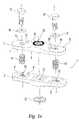
- FIGS. 1A , 1 B and 1 Care two exploded perspective views and an elevation view of a bone pin vise portion, a bone pin vise opposing plate and star grind cover, and a bone pin vise opposing plate incorporating triangular bone pin clamping grooves, respectively, of the bone pin locking assembly of the current invention;
- FIG. 2is an exploded perspective view of a rod attachment portion of the bone pin locking assembly of the current invention
- FIG. 3is a perspective view of an assembled bone pin vise portion of FIG. 1 connected to an assembled rod attachment portion of FIG. 2 ;
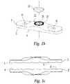
- FIG. 4is an exploded perspective view of the single piece fixation rod clamp
- FIG. 5is a cross-sectional view of the single-piece fixation rod clamp and a bone fixation rod
- FIG. 6is a perspective view of a complete bone fixation device installed on a bone.
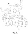
- FIG. 7is a perspective view of the stacked clamp assembly embodiment of the present invention.
- the traumatological device of the present inventionis discussed herein with reference to a preferred embodiment adapted to be used in the consolidation and fixation of a fractured long bone. It is to be understood that the invention finds applicability for use in any circumstance in which it is desired to fix the orientation of bone segments on either side of a fracture.
- FIG. 1Ashows an exploded view of a bone pin vise portion.
- the bone pin vise portion 1comprises first and second opposing plates 2 and 2 ′ with engaging faces 4 and 4 ′, and outside faces 6 and 6 ′.
- Each engaging faceis characterized by a plurality of spaced parallel grooves 8 and 8 ′ which are cylindrically arcuate and which are in confronting relation to the spaced parallel grooves on the face of the opposite plate.
- the parallel grooves 8 and 8 ′coordinate to receive the proximal ends of bone pins 28 (shown in FIG. 6 ) installed on one side of a fractured bone.
- the bone pins 28are nested in the respective grooves formed by the conjunction of parallel grooves 8 and 8 ′ (of engaging faces 4 and 4 ′). It will be understood that the number and shape of the grooves is not critical to the operation of the device.
- the opposing plates 2 and 2 ′are connected by two vise bolts 12 and 12 ′ which operate to draw together engaging faces 4 and 4 ′ in order to grip the proximal ends of bone pins 28 which have been installed in a bone.
- Vise bolts 12 and 12 ′are slideably accepted by corresponding bores 14 and 14 ′ in each end of first opposing plate 2 , and are threadably accepted by threaded bores 16 and 16 ′ in each end of second opposing plate 2 ′.
- first opposing plate 2incorporates bolt head bearing surfaces 30 and 30 ′ to provide uniform bearing contact with the bottoms of the heads of pin vice bolts 12 and 12 ′.
- the vise bolts 12 and 12 ′may be provided with washers 18 and 18 ′ positioned between the heads of the vice bolts 12 and 12 ′, and bolt head bearing surfaces 30 and 30 ′ of the pin vise portion opposing plate 2 .
- the washersserve to reduce friction between the vise bolts and bolt head bearing surfaces, thereby easing final tightening of the vise bolts.
- the vise bolts 12 and 12 ′will be initially fit with the washers 18 and 18 ′, then installed in the opposing plates, followed by a “loose-fit” tightening to the point that only a small clearance remains between the cylindrical voids formed by the plurality of spaced parallel grooves 8 and 8 ′ and the outside surfaces of the cylindrical bone pins 28 .
- the pin vise portion 1may easily be slipped onto the bone pins 28 , such that during the surgical procedure only minor additional tightening of the vise bolts 12 and 12 ′ will be required to firmly fix the bone pins 28 within the bone pin vise portion 1 .
- the pin vise portion opposing plates 2 and 2 ′incorporate coil springs 10 and 10 ′ between engaging faces 4 and 4 ′ to forcibly separate engaging faces 4 and 4 ′.
- the provision of this separating forceholds the plates apart during installation of the pin vise portion onto the bone pin proximal ends, easing such installation.
- cylindrical coil springs 10 and 10 ′are installed about the shafts of vise bolts 12 and 12 ′ such that vise bolt shafts are slidably received by the bore formed within the inside diameter of each coil spring 10 and 10 ′ (see FIG. 3 ).
- FIG. 2shows an exploded view of a rod attachment portion 50 , comprising a single-piece fixation rod clamp 56 , a coupling 52 , a coil spring 68 , and a coupling bolt 64 .
- the single-piece fixation rod clamphas a cylindrical coupling portion 58 which is slidably disposed within an aperture 54 formed by the body of the coupling 52 .
- Single-piece fixation rod clamp 56is thus interconnected to and slidably disposed within the coupling 52 so as to allow 360-degree rotation of the single-piece fixation rod clamp 56 within the coupling aperture 54 .
- the coupling bolt 64having a head and a threaded distal end 66 , is slidably disposed within a bore 70 formed in the body of coupling 52 .
- the longitudinal axis of bore 70is oriented perpendicular to that of the coupling aperture 54 .
- the coupling bolt threaded distal end 66is threadably accepted by an internally and compatibly threaded bore 26 formed in the top center of opposing plate 2 (shown in FIG. 1A ) of pin vise portion 1 (shown in FIG. 1A ).
- the single-piece fixation rod clamp 56is thus interconnected to and rotatably disposed about pin vise portion 1 .
- the single-piece fixation rod clamp 56is interconnected to and rotatably disposed, with two degrees of rotational freedom, about pin vise portion 1 , and so about bone pins 28 (shown in FIG. 6 ).
- the first degree of rotational freedomis provided by the rotation of single-piece fixation rod clamp 56 relative to the rod attachment portion coupling 52 ; the second by the rotation of the rod attachment portion coupling relative to pin vise portion 1 .
- the single-piece fixation rod clamp 56is stabilized and fixed to the rod attachment portion coupling 52 by tightening the coupling bolt 64 . Tightening of the coupling bolt 64 also results in the stabilization and fixation of the entire rod attachment portion 50 to the pin vise portion 1 .
- the coupling 52has a bearing face 60 incorporating serrations 62 which extend over the entire face, and which correspond with like serrations 24 (shown in FIG. 1A ) formed in the corresponding bearing face of the pin vise portion 1 .
- the serrationsmay be disposed in a radial fashion to form a “star grind,” or may have any type of profile known in the art.
- the serrations 62 , 24serve to minimize or prevent rotational slippage between the coupling 52 and the pin vise portion 1 subsequent to final tightening of the coupling bolt 64 .
- the pin vise portion opposing plate 2 ′incorporates an internally threaded bore 20 , into which the coupling bolt 64 of a second rod attachment portion 50 (shown in FIG. 2 ) may be threaded.
- the bearing face 21 of the pin vise portion opposing plate 2 ′incorporates serrations 23 which extend over the entire face, and which correspond with like serrations 62 of the bearing face 60 of a second rod attachment portion 50 (shown in FIG. 2 ).
- the serrations 62 , 23serve to minimize or prevent rotational slippage between the second coupling 52 and the pin vise portion 1 subsequent to final tightening of the second coupling bolt 64 .
- Two rod attachment portions 50may thereby be installed on one pin vise portion 1 to provide the fracture site with the additional stabilizing force of a second bone fixation rod 100 (shown in FIG. 6 ).
- an externally threaded “star grind” cover 22(shown in FIGS. 1A and 1B ) is provided.
- the coveris threadably accepted by the internally threaded bore 20 of the pin vise portion opposing plate 2 ′ (shown in FIGS. 1A and 1B ).
- the cover 22may have a bearing face 25 (shown in FIG. 1A ) incorporating serrations 27 which extend over the entire face, and which correspond with like serrations 23 (shown in FIG.
- the serrationsmay be disposed in a radial fashion to form a “star grind,” or may have any type of profile known in the art.
- the serrations 23 , 27serve to minimize or prevent rotational slippage between the star grind cover 22 and the pin vise portion 1 subsequent to final tightening of the star grind cover.
- the coupling bolt 64may be provided with a coil spring 68 disposed about the circumference of the bolt 64 .
- the springis partially slidably received within a bore 71 provided in the coupling bearing face 60 .
- This boreis of larger diameter than coupling bore 70 , which results in the creation of a circumferential ledge 72 within the coupling 52 .
- the spring 68acts to provide a force tending to separate the coupling 52 and the pin vise portion 1 . This force prevents engagement of the serrations 62 , 24 (and serrations 62 , 23 in the alternative embodiment where a second bone fixation rod is utilized) during installation, and thus enables easy relative rotation and fit-up.
- FIG. 4shows the details of the novel single-piece fixation rod clamp 56 of the present invention.
- the single-piece fixation rod clampcomprises a jaw portion 80 , which further comprises a set of opposing jaws 82 and 82 ′, each connected to a respective spring arm 86 and 86 ′.
- the spring armsconverge to a smooth cylindrical coupling portion 58 .
- the jaw portion 80is manufactured in a single piece, so that when the jaws 82 and 82 ′ are positively displaced with respect to their rest position, a resulting spring force is generated which tends to force the jaws back to the rest position.
- the jaw portion 80is preferably manufactured such that the initial clearance “X” between opposing jaws 82 and 82 ′ is slightly smaller than the outside diameter “Y” of the bone fixation rod 100 (shown in FIG. 5 ). In this way an interference is established between jaws 82 and 82 ′ and the bone fixation rod 100 when the bone fixation rod is initially installed into the jaw portion 80 .
- the relative interference between the jaws and the bone fixation rodenables the entire bone pin locking assembly (comprising pin vise portion 1 and rod attachment portion 50 ) to be snapped onto the bone fixation rod 100 by the operator, resulting in the capture of the bone fixation rod 100 within the rod attachment jaw portion 80 .
- the spring action of the spring armsis sufficient to maintain a loose coupling of the assembly with the rod. This frees up the hands of the surgeon performing the fixation procedure.
- Final stabilization of the bone fixation rod 100 within the jaw portion 80is accomplished through the use of a bolt 92 placed through the jaw portion spring arms 86 and 86 ′, in combination with a nut 90 (see FIG. 4 ).
- the spring arms 86 and 86 ′and most importantly for the purposes of the invention, the adjoining jaws 82 and 82 ′, are drawn together until the bone fixation rod 100 is firmly held between the jaws 82 and 82 ′. Repeated loosening and tightening of the rod attachment portion on the bone fixation rod is possible without the need for re-engagement of the rod within the jaw. In this way the surgeon may easily and multiply adjust the position of the rod attachment portion along the bone fixation rod.
- An external hexagon 94may be provided integral to the shoulder of the jaw bolt 92 .
- This external hexagon 94conforms to an internal hexagonal recess 96 provided within jaw portion spring arm 86 .
- the boltis thereby rotationally fixed to the jaw portion, such that the surgeon need only focus on threading the nut onto the bolt without having to worry about holding the bolt still.
- a washer 88may be provided between the nut 90 and jaw portion spring arm 86 ′.
- This washercan be of any design known in the art satisfactory to prevent galling of the nut and jaw portion spring arm, and to facilitate installation of nut 90 and bolt 92 .
- FIG. 7shows a “stacked” bone pin locking assembly which comprises one pin vise portion 1 with two associated rod attachment portions 50 .
- Such a stacked assemblypermits the surgeon to provide an additional stabilizing force, associated with a second bone fixation rod 100 , to the fracture site. In this way a framework of bone fixation rods may be built about the fracture site.
Landscapes
- Health & Medical Sciences (AREA)
- Orthopedic Medicine & Surgery (AREA)
- Life Sciences & Earth Sciences (AREA)
- Surgery (AREA)
- Medical Informatics (AREA)
- Engineering & Computer Science (AREA)
- Biomedical Technology (AREA)
- Heart & Thoracic Surgery (AREA)
- Nuclear Medicine, Radiotherapy & Molecular Imaging (AREA)
- Molecular Biology (AREA)
- Animal Behavior & Ethology (AREA)
- General Health & Medical Sciences (AREA)
- Public Health (AREA)
- Veterinary Medicine (AREA)
- Surgical Instruments (AREA)
- Prostheses (AREA)
Abstract
Description
Claims (24)
Priority Applications (3)
| Application Number | Priority Date | Filing Date | Title |
|---|---|---|---|
| US10/402,897US7699848B2 (en) | 2000-12-14 | 2003-03-28 | Multipin clamp and rod attachment |
| US12/715,797US8372073B2 (en) | 2000-12-14 | 2010-03-02 | Multi-pin clamp and rod attachment |
| US13/738,461US8998902B2 (en) | 2000-12-14 | 2013-01-10 | Multi-pin clamp and rod attachment |
Applications Claiming Priority (2)
| Application Number | Priority Date | Filing Date | Title |
|---|---|---|---|
| US09/736,753US6565564B2 (en) | 2000-12-14 | 2000-12-14 | Multi-pin clamp and rod attachment |
| US10/402,897US7699848B2 (en) | 2000-12-14 | 2003-03-28 | Multipin clamp and rod attachment |
Related Parent Applications (1)
| Application Number | Title | Priority Date | Filing Date |
|---|---|---|---|
| US09/736,753ContinuationUS6565564B2 (en) | 2000-12-14 | 2000-12-14 | Multi-pin clamp and rod attachment |
Related Child Applications (1)
| Application Number | Title | Priority Date | Filing Date |
|---|---|---|---|
| US12/715,797ContinuationUS8372073B2 (en) | 2000-12-14 | 2010-03-02 | Multi-pin clamp and rod attachment |
Publications (2)
| Publication Number | Publication Date |
|---|---|
| US20030191468A1 US20030191468A1 (en) | 2003-10-09 |
| US7699848B2true US7699848B2 (en) | 2010-04-20 |
Family
ID=24961168
Family Applications (6)
| Application Number | Title | Priority Date | Filing Date |
|---|---|---|---|
| US09/736,753Expired - LifetimeUS6565564B2 (en) | 2000-12-14 | 2000-12-14 | Multi-pin clamp and rod attachment |
| US10/402,897Expired - LifetimeUS7699848B2 (en) | 2000-12-14 | 2003-03-28 | Multipin clamp and rod attachment |
| US10/402,896Expired - LifetimeUS7041103B2 (en) | 2000-12-14 | 2003-03-28 | Multipin clamp and rod attachment |
| US11/388,153Expired - LifetimeUS7875030B2 (en) | 2000-12-14 | 2006-03-22 | Multipin clamp and rod attachment |
| US12/715,797Expired - Fee RelatedUS8372073B2 (en) | 2000-12-14 | 2010-03-02 | Multi-pin clamp and rod attachment |
| US13/738,461Expired - Fee RelatedUS8998902B2 (en) | 2000-12-14 | 2013-01-10 | Multi-pin clamp and rod attachment |
Family Applications Before (1)
| Application Number | Title | Priority Date | Filing Date |
|---|---|---|---|
| US09/736,753Expired - LifetimeUS6565564B2 (en) | 2000-12-14 | 2000-12-14 | Multi-pin clamp and rod attachment |
Family Applications After (4)
| Application Number | Title | Priority Date | Filing Date |
|---|---|---|---|
| US10/402,896Expired - LifetimeUS7041103B2 (en) | 2000-12-14 | 2003-03-28 | Multipin clamp and rod attachment |
| US11/388,153Expired - LifetimeUS7875030B2 (en) | 2000-12-14 | 2006-03-22 | Multipin clamp and rod attachment |
| US12/715,797Expired - Fee RelatedUS8372073B2 (en) | 2000-12-14 | 2010-03-02 | Multi-pin clamp and rod attachment |
| US13/738,461Expired - Fee RelatedUS8998902B2 (en) | 2000-12-14 | 2013-01-10 | Multi-pin clamp and rod attachment |
Country Status (9)
| Country | Link |
|---|---|
| US (6) | US6565564B2 (en) |
| EP (1) | EP1341458A2 (en) |
| JP (1) | JP4448655B2 (en) |
| AR (1) | AR032785A1 (en) |
| AU (1) | AU2002212034A1 (en) |
| BR (1) | BR0116177A (en) |
| CA (1) | CA2431802C (en) |
| MX (1) | MXPA03005229A (en) |
| WO (2) | WO2002047531A2 (en) |
Cited By (13)
| Publication number | Priority date | Publication date | Assignee | Title |
|---|---|---|---|---|
| US8834467B2 (en) | 2010-08-11 | 2014-09-16 | Stryker Trauma Sa | External fixator system |
| US8858555B2 (en) | 2009-10-05 | 2014-10-14 | Stryker Trauma Sa | Dynamic external fixator and methods for use |
| US8945128B2 (en) | 2010-08-11 | 2015-02-03 | Stryker Trauma Sa | External fixator system |
| US9101398B2 (en) | 2012-08-23 | 2015-08-11 | Stryker Trauma Sa | Bone transport external fixation frame |
| US9848912B1 (en) | 2015-04-07 | 2017-12-26 | Matthew James Endara | Adjustment assembly for external fixator assembly |
| US9872707B2 (en) | 2015-12-03 | 2018-01-23 | Globus Medical, Inc. | External fixator assembly |
| US9943337B2 (en) | 2015-12-03 | 2018-04-17 | Globus Medical, Inc. | External fixator assembly |
| US10010350B2 (en) | 2016-06-14 | 2018-07-03 | Stryker European Holdings I, Llc | Gear mechanisms for fixation frame struts |
| US10070890B2 (en) | 2015-12-03 | 2018-09-11 | Globus Medical Inc | External fixator assembly |
| US10478224B1 (en) | 2017-02-24 | 2019-11-19 | Christopher D. Endara | Distraction clamp for treating injuries |
| US10874433B2 (en) | 2017-01-30 | 2020-12-29 | Stryker European Holdings I, Llc | Strut attachments for external fixation frame |
| US11141196B2 (en) | 2010-08-11 | 2021-10-12 | Stryker European Operations Holdings Llc | External fixator system |
| US11672566B2 (en) | 2015-12-03 | 2023-06-13 | Globus Medical, Inc. | External fixator assembly |
Families Citing this family (117)
| Publication number | Priority date | Publication date | Assignee | Title |
|---|---|---|---|---|
| US6565564B2 (en)* | 2000-12-14 | 2003-05-20 | Synthes U.S.A. | Multi-pin clamp and rod attachment |
| US7004943B2 (en)* | 2002-02-04 | 2006-02-28 | Smith & Nephew, Inc. | Devices, systems, and methods for placing and positioning fixation elements in external fixation systems |
| US7758582B2 (en)* | 2002-06-14 | 2010-07-20 | Smith & Nephew, Inc. | Device and methods for placing external fixation elements |
| US7608074B2 (en)* | 2003-01-10 | 2009-10-27 | Smith & Nephew, Inc. | External fixation apparatus and method |
| US7261715B2 (en) | 2003-11-24 | 2007-08-28 | Sdgi Holdings, Inc. | Grommet assembly |
| US7588590B2 (en)* | 2003-12-10 | 2009-09-15 | Facet Solutions, Inc | Spinal facet implant with spherical implant apposition surface and bone bed and methods of use |
| KR100989362B1 (en) | 2004-02-17 | 2010-10-25 | 한국항공우주산업 주식회사 | Locator for Aircraft Workpiece Alignment |
| US8034082B2 (en) | 2004-07-08 | 2011-10-11 | Globus Medical, Inc. | Transverse fixation device for spinal fixation systems |
| ES2326269T3 (en)* | 2004-08-20 | 2009-10-06 | Stryker Trauma Sa | TIGHTENING ELEMENT AND GASKET ELEMENT. |
| EP1627609B1 (en)* | 2004-08-20 | 2007-10-17 | Stryker Trauma SA | Clamping element for clamping of several rod-like elements |
| US8118836B2 (en) | 2004-11-05 | 2012-02-21 | Biomet Sports Medicine, Llc | Method and apparatus for coupling soft tissue to a bone |
| US7749250B2 (en) | 2006-02-03 | 2010-07-06 | Biomet Sports Medicine, Llc | Soft tissue repair assembly and associated method |
| US8128658B2 (en) | 2004-11-05 | 2012-03-06 | Biomet Sports Medicine, Llc | Method and apparatus for coupling soft tissue to bone |
| US9017381B2 (en) | 2007-04-10 | 2015-04-28 | Biomet Sports Medicine, Llc | Adjustable knotless loops |
| US8298262B2 (en) | 2006-02-03 | 2012-10-30 | Biomet Sports Medicine, Llc | Method for tissue fixation |
| US8361113B2 (en) | 2006-02-03 | 2013-01-29 | Biomet Sports Medicine, Llc | Method and apparatus for coupling soft tissue to a bone |
| US7658751B2 (en) | 2006-09-29 | 2010-02-09 | Biomet Sports Medicine, Llc | Method for implanting soft tissue |
| US8303604B2 (en) | 2004-11-05 | 2012-11-06 | Biomet Sports Medicine, Llc | Soft tissue repair device and method |
| US8088130B2 (en) | 2006-02-03 | 2012-01-03 | Biomet Sports Medicine, Llc | Method and apparatus for coupling soft tissue to a bone |
| US9801708B2 (en) | 2004-11-05 | 2017-10-31 | Biomet Sports Medicine, Llc | Method and apparatus for coupling soft tissue to a bone |
| US7909851B2 (en) | 2006-02-03 | 2011-03-22 | Biomet Sports Medicine, Llc | Soft tissue repair device and associated methods |
| US8137382B2 (en) | 2004-11-05 | 2012-03-20 | Biomet Sports Medicine, Llc | Method and apparatus for coupling anatomical features |
| US7905904B2 (en) | 2006-02-03 | 2011-03-15 | Biomet Sports Medicine, Llc | Soft tissue repair device and associated methods |
| US20060229605A1 (en)* | 2005-03-18 | 2006-10-12 | Olsen Ron A | Adjustable splint for osteosynthesis with incrementing assembly for adjustment in predetermined increments |
| US7575575B2 (en)* | 2005-03-18 | 2009-08-18 | Ron Anthon Olsen | Adjustable splint for osteosynthesis with modular components |
| DE202005005444U1 (en)* | 2005-04-01 | 2005-06-02 | Tantum Ag | Particularly stable bone fixing device, assembled of two central elements and two fixing rods holding devices |
| US7722609B2 (en)* | 2005-04-25 | 2010-05-25 | Synthes Usa, Llc | Outrigger with locking mechanism |
| US8758343B2 (en) | 2005-04-27 | 2014-06-24 | DePuy Synthes Products, LLC | Bone fixation apparatus |
| GB2425958A (en)* | 2005-05-10 | 2006-11-15 | Veterinary Innovations Ltd | Collet type pin clamp for an external fracture fixator or distractor |
| GB2427141B (en)* | 2005-06-13 | 2010-12-22 | Intelligent Orthopaedics Ltd | Fixator |
| US8523858B2 (en)* | 2005-06-21 | 2013-09-03 | DePuy Synthes Products, LLC | Adjustable fixation clamp and method |
| US20060289577A1 (en)* | 2005-06-23 | 2006-12-28 | Malone Larry D | Universal attachment system |
| ES2246744B1 (en)* | 2005-10-11 | 2006-12-01 | Implantvet, S.L. | ARTICULATION FOR MUTUAL SOLIDARIZATION BETWEEN BARS AND / OR NEEDLES IN AN EXTERNAL FIXING DEVICE FOR THE REDUCTION OF OSE FRACTURES. |
| US7803174B2 (en) | 2005-11-04 | 2010-09-28 | Warsaw Orthopedic, Inc. | Dorsal adjusting multi-rod connector |
| US7731738B2 (en)* | 2005-12-09 | 2010-06-08 | Orthopro, Llc | Cannulated screw |
| US11311287B2 (en) | 2006-02-03 | 2022-04-26 | Biomet Sports Medicine, Llc | Method for tissue fixation |
| US11259792B2 (en) | 2006-02-03 | 2022-03-01 | Biomet Sports Medicine, Llc | Method and apparatus for coupling anatomical features |
| US8652171B2 (en) | 2006-02-03 | 2014-02-18 | Biomet Sports Medicine, Llc | Method and apparatus for soft tissue fixation |
| US8801783B2 (en) | 2006-09-29 | 2014-08-12 | Biomet Sports Medicine, Llc | Prosthetic ligament system for knee joint |
| US9468433B2 (en) | 2006-02-03 | 2016-10-18 | Biomet Sports Medicine, Llc | Method and apparatus for forming a self-locking adjustable loop |
| US10517587B2 (en) | 2006-02-03 | 2019-12-31 | Biomet Sports Medicine, Llc | Method and apparatus for forming a self-locking adjustable loop |
| US8562647B2 (en) | 2006-09-29 | 2013-10-22 | Biomet Sports Medicine, Llc | Method and apparatus for securing soft tissue to bone |
| US9149267B2 (en) | 2006-02-03 | 2015-10-06 | Biomet Sports Medicine, Llc | Method and apparatus for coupling soft tissue to a bone |
| US9078644B2 (en) | 2006-09-29 | 2015-07-14 | Biomet Sports Medicine, Llc | Fracture fixation device |
| US8968364B2 (en) | 2006-02-03 | 2015-03-03 | Biomet Sports Medicine, Llc | Method and apparatus for fixation of an ACL graft |
| US8597327B2 (en) | 2006-02-03 | 2013-12-03 | Biomet Manufacturing, Llc | Method and apparatus for sternal closure |
| US8562645B2 (en) | 2006-09-29 | 2013-10-22 | Biomet Sports Medicine, Llc | Method and apparatus for forming a self-locking adjustable loop |
| EP1820461B1 (en) | 2006-02-21 | 2009-08-05 | Stryker Trauma SA | Clamping and articulation element |
| US7708736B2 (en)* | 2006-02-22 | 2010-05-04 | Extraortho, Inc. | Articulation apparatus for external fixation device |
| EP2016655B1 (en)* | 2006-04-28 | 2011-11-30 | Telefonaktiebolaget LM Ericsson (PUBL) | A cable suspension device |
| EP1862135B1 (en)* | 2006-05-29 | 2017-07-05 | Stryker European Holdings I, LLC | Clamping element and insert therefor |
| US7988711B2 (en) | 2006-09-21 | 2011-08-02 | Warsaw Orthopedic, Inc. | Low profile vertebral stabilization systems and methods |
| US8672969B2 (en) | 2006-09-29 | 2014-03-18 | Biomet Sports Medicine, Llc | Fracture fixation device |
| US11259794B2 (en) | 2006-09-29 | 2022-03-01 | Biomet Sports Medicine, Llc | Method for implanting soft tissue |
| EP1920720B1 (en)* | 2006-10-13 | 2014-03-19 | Stryker Trauma SA | Prevention of re-use of a medical device |
| AU2008318535B2 (en) | 2007-10-31 | 2014-06-19 | Wright Medical Technology, Inc. | Orthopedic device |
| US8118868B2 (en)* | 2008-04-22 | 2012-02-21 | Biomet Manufacturing Corp. | Method and apparatus for attaching soft tissue to an implant |
| US8187274B2 (en)* | 2008-06-30 | 2012-05-29 | Depuy Products, Inc. | External fixator |
| US12419632B2 (en) | 2008-08-22 | 2025-09-23 | Biomet Sports Medicine, Llc | Method and apparatus for coupling anatomical features |
| US12245759B2 (en) | 2008-08-22 | 2025-03-11 | Biomet Sports Medicine, Llc | Method and apparatus for coupling soft tissue to bone |
| IT1391222B1 (en)* | 2008-09-11 | 2011-12-01 | Orthofix Srl | ORTHOPEDIC DEVICE TO BE ASSOCIATED WITH A BONE |
| GB2465156B (en) | 2008-11-05 | 2012-09-26 | Dalmatic Lystrup As | Bone fixation system |
| GB2465335B (en)* | 2008-11-05 | 2012-08-15 | Dalmatic Lystrup As | Bone fixation device |
| ES2451507T3 (en) | 2009-05-15 | 2014-03-27 | Stryker Trauma Ag | Fixing flange |
| US12096928B2 (en) | 2009-05-29 | 2024-09-24 | Biomet Sports Medicine, Llc | Method and apparatus for coupling soft tissue to a bone |
| EP2294995B1 (en)* | 2009-09-11 | 2018-04-04 | Stryker European Holdings I, LLC | Easy to clean clamping device |
| EP2294994B1 (en)* | 2009-09-11 | 2018-04-04 | Stryker European Holdings I, LLC | External fixation component |
| USD632791S1 (en) | 2009-09-11 | 2011-02-15 | Stryker Trauma Ag | Connector |
| US20110098748A1 (en)* | 2009-10-26 | 2011-04-28 | Warsaw Orthopedic, Inc. | Adjustable vertebral rod system and methods of use |
| EP2319436B1 (en)* | 2009-11-06 | 2013-02-13 | ORTHOFIX S.r.l. | Clamp for external orthopaedic fixing device |
| BR112013002146A2 (en)* | 2010-07-30 | 2016-05-31 | Smith & Nephew Inc | double acting external clamp |
| ES2541831T3 (en) | 2010-10-07 | 2015-07-27 | Stryker Trauma Sa | Coupling element for an external fixing device |
| EP2465454B1 (en) | 2010-12-14 | 2015-04-08 | Stryker Trauma SA | Fixation clamp with thumbwheel |
| ES2540256T3 (en) | 2010-12-14 | 2015-07-09 | Stryker Trauma Sa | Fixing clamp |
| EP2465455B1 (en) | 2010-12-14 | 2015-04-08 | Stryker Trauma SA | Fixation clamp |
| USD720853S1 (en) | 2010-12-14 | 2015-01-06 | Stryker Trauma Sa | Fixation clamp |
| USD704840S1 (en) | 2010-12-14 | 2014-05-13 | Stryker Trauma Sa | Hinge coupling |
| USD683461S1 (en) | 2010-12-14 | 2013-05-28 | Stryker Trauma Sa | Hinge coupling |
| US12329373B2 (en) | 2011-05-02 | 2025-06-17 | Biomet Sports Medicine, Llc | Method and apparatus for soft tissue fixation |
| JP6106662B2 (en)* | 2011-05-17 | 2017-04-05 | ジンマー,インコーポレイティド | External fixed clamping system using a starting mechanism and stored spring energy |
| USD663030S1 (en) | 2011-06-14 | 2012-07-03 | Styker Trauma SA | Fixation clamp |
| USD682426S1 (en) | 2011-06-14 | 2013-05-14 | Stryker Trauma Sa | Fixation clamp |
| US9357991B2 (en) | 2011-11-03 | 2016-06-07 | Biomet Sports Medicine, Llc | Method and apparatus for stitching tendons |
| US9314241B2 (en) | 2011-11-10 | 2016-04-19 | Biomet Sports Medicine, Llc | Apparatus for coupling soft tissue to a bone |
| US9381013B2 (en) | 2011-11-10 | 2016-07-05 | Biomet Sports Medicine, Llc | Method for coupling soft tissue to a bone |
| US20130123854A1 (en)* | 2011-11-16 | 2013-05-16 | Dimitriy G. Kondrashov | System and method for spinal stabilization through mutli-head spinal screws |
| US9924969B2 (en) | 2012-09-04 | 2018-03-27 | Zimmer, Inc. | External fixation |
| US9301782B2 (en) | 2012-09-04 | 2016-04-05 | Zimmer, Inc. | External fixation |
| US9918827B2 (en) | 2013-03-14 | 2018-03-20 | Biomet Sports Medicine, Llc | Scaffold for spring ligament repair |
| EP2967671B1 (en)* | 2013-03-15 | 2021-11-17 | Biomet C.V. | Polyaxial pivot housing for external fixation system |
| ITMI20130407A1 (en)* | 2013-03-18 | 2014-09-19 | Orthofix Srl | EXTERNAL FIXING DEVICE |
| WO2015014441A1 (en)* | 2013-07-31 | 2015-02-05 | Orthofix S.R.L. | Device for locking uni-cortical pins |
| EP3052203A4 (en) | 2013-09-30 | 2017-08-23 | Silk Therapeutics Inc. | Silk protein fragment compositions and articles manufactured therefrom |
| US9962188B2 (en) | 2013-10-29 | 2018-05-08 | Cardinal Health 247. Inc. | External fixation system and methods of use |
| TR201808775T4 (en)* | 2013-12-24 | 2018-07-23 | Akeso Ag | External fixator. |
| US9962187B2 (en) | 2014-08-11 | 2018-05-08 | Zimmer, Inc. | External fixation |
| EP3242616A1 (en)* | 2015-01-09 | 2017-11-15 | Biomet Manufacturing, LLC | Surgical clamps |
| USD762110S1 (en)* | 2015-04-26 | 2016-07-26 | Kevin J. Olson | Bar clamp |
| WO2016205128A2 (en) | 2015-06-17 | 2016-12-22 | Nathan Erickson | Ankle fixation system |
| EP3322434B1 (en) | 2015-07-14 | 2024-12-11 | Evolved by Nature, Inc. | Silk performance apparel and products and methods of preparing the same |
| US10531896B2 (en)* | 2015-08-10 | 2020-01-14 | Stryker European Holdings I, Llc | Distraction tube with wire clamp |
| US20170265904A1 (en)* | 2016-03-16 | 2017-09-21 | Globus Medical, Inc. | Transverse connectors for spinal systems |
| DE202017101471U1 (en)* | 2017-03-14 | 2017-04-11 | Kemmann & Koch Gmbh & Co. Kg | Articulated fitting especially for furniture |
| EP3381387B1 (en)* | 2017-03-30 | 2020-09-30 | Globus Medical, Inc. | External fixator assembly |
| US11390988B2 (en) | 2017-09-27 | 2022-07-19 | Evolved By Nature, Inc. | Silk coated fabrics and products and methods of preparing the same |
| US11571243B2 (en) | 2018-05-18 | 2023-02-07 | Beth Israel Deaconess Medical Center, Inc. | External fixation clamp and systems for medical procedures |
| US10989333B2 (en)* | 2019-01-03 | 2021-04-27 | The Boeing Company | Adjustable clamp systems and methods |
| USD957635S1 (en) | 2019-05-17 | 2022-07-12 | Beth Israel Deaconess Medical Center, Inc. | External medical fixation clamp |
| USD1010122S1 (en) | 2019-05-17 | 2024-01-02 | Lifecell Corporation | External fixation clamp for medical procedures |
| IT201900007314A1 (en) | 2019-05-27 | 2020-11-27 | Orthofix Srl | Quick-connect clamp for external fixation systems |
| WO2022168057A1 (en) | 2021-02-08 | 2022-08-11 | Nelson Saldanha Kiran Antony | System and devices for closed fracture reduction, deformity correction and fixation of bone |
| US11413070B2 (en)* | 2021-11-22 | 2022-08-16 | New Standard Device, LLC | Locking clamp and external fixation horns |
| CN114848111A (en)* | 2022-03-30 | 2022-08-05 | 四川维思达医疗器械有限公司 | External fixator for small bones |
| US20240225699A1 (en)* | 2023-01-09 | 2024-07-11 | Smith & Nephew, Inc. | External fixation k-wire clamp and corresponding method of use |
| US12336741B2 (en)* | 2023-03-14 | 2025-06-24 | Warsaw Orthopedic, Inc. | Surgical system and methods of use |
| IT202300007383A1 (en)* | 2023-04-17 | 2024-10-17 | Citieffe Srl | EXTERNAL FIXING DEVICE CLAMP |
| CN119970198B (en)* | 2025-04-16 | 2025-07-18 | 天津市威曼生物材料有限公司 | Combined fracture internal fixing device |
Citations (61)
| Publication number | Priority date | Publication date | Assignee | Title |
|---|---|---|---|---|
| US1997466A (en) | 1934-04-23 | 1935-04-09 | Harry Herschel Leiter | Surgical appliance |
| US2250417A (en) | 1939-12-02 | 1941-07-22 | Zimmer Mfg Company | Fracture reduction and retention device |
| US2346346A (en) | 1941-01-21 | 1944-04-11 | Anderson Roger | Fracture immobilization splint |
| US2391693A (en) | 1943-12-09 | 1945-12-25 | Zimmer Mfg Company | Surgical splint |
| US2391537A (en) | 1943-09-27 | 1945-12-25 | Anderson Roger | Ambulatory rotating reduction and fixation splint |
| US4135505A (en) | 1976-04-30 | 1979-01-23 | National Research Development Corporation | Orthopaedic fracture fixing apparatus |
| US4271832A (en) | 1978-07-20 | 1981-06-09 | National Research Development Corporation | Post-fracture stability of limbs |
| US4312336A (en) | 1978-11-10 | 1982-01-26 | Orthofix S.R.1. | External axial fixation unit |
| US4365624A (en) | 1979-01-16 | 1982-12-28 | Jaquet Orthopedie Sa | External bone-anchoring element |
| US4411259A (en)* | 1980-02-04 | 1983-10-25 | Drummond Denis S | Apparatus for engaging a hook assembly to a spinal column |
| US4483334A (en) | 1983-04-11 | 1984-11-20 | Murray William M | External fixation device |
| US4502473A (en) | 1981-08-06 | 1985-03-05 | National Research Development Corp. | Apparatus for external fixation of bone fractures |
| US4541422A (en) | 1981-12-09 | 1985-09-17 | Zbikowski Juan | Functional attachment system for osteosynthesis |
| US4620533A (en) | 1985-09-16 | 1986-11-04 | Pfizer Hospital Products Group Inc. | External bone fixation apparatus |
| US4621627A (en) | 1984-12-18 | 1986-11-11 | Orthofix S.R.L. | External axial fixation device |
| US4628922A (en) | 1984-09-28 | 1986-12-16 | University College London | Fracture reduction apparatus |
| US4628919A (en) | 1983-09-09 | 1986-12-16 | Clyburn Terry | Dynamic external fixator and method of use |
| US4714076A (en) | 1984-01-19 | 1987-12-22 | Synthes | Device for the setting of bone segments |
| US4922896A (en) | 1989-05-05 | 1990-05-08 | John M. Agee | Colles' fracture splint |
| US4941481A (en) | 1985-11-29 | 1990-07-17 | Jaquet Orthopedie, S.A. | Device for positioning and securing a part having circular regions |
| US4988349A (en) | 1987-01-21 | 1991-01-29 | Orthofix S.R.L. | Device for osteosynthesis |
| US5053034A (en) | 1990-08-03 | 1991-10-01 | Sven Olerud | Spinal joint |
| US5108394A (en) | 1989-09-08 | 1992-04-28 | Kabushiki Kaisha Nagano Keiki Seisakusho | Bone fixing device |
| US5152280A (en) | 1989-01-04 | 1992-10-06 | Confida S.A.S | Bone support device |
| US5160335A (en) | 1988-12-15 | 1992-11-03 | Jaquet Orthopedie S.A. | Pin holder support |
| US5207676A (en) | 1989-02-27 | 1993-05-04 | Jaquet Orthopedie S.A. | External fixator with controllable damping |
| US5219349A (en) | 1991-02-15 | 1993-06-15 | Howmedica, Inc. | Spinal fixator reduction frame |
| US5292322A (en) | 1991-11-05 | 1994-03-08 | Orthofix S.R.L. | Clamping coupling for an external fixator |
| US5320622A (en) | 1992-07-28 | 1994-06-14 | Orthofix S.R.L. | Dynamic axial splint |
| US5320623A (en) | 1991-07-16 | 1994-06-14 | Orthofix S.R.1. | Clamping coupling for an external fixator |
| US5376090A (en) | 1991-07-12 | 1994-12-27 | Orthofix S.R.L. | Clamping coupling |
| US5454810A (en) | 1990-02-05 | 1995-10-03 | Pohl; Anthony P. | External fixation device |
| US5624440A (en) | 1996-01-11 | 1997-04-29 | Huebner; Randall J. | Compact small bone fixator |
| US5630815A (en) | 1994-08-05 | 1997-05-20 | Pohl; Anthony P. | External fixator for military use |
| US5658283A (en) | 1995-02-15 | 1997-08-19 | Huebner; Randall J. | External fixator for repairing fractures |
| US5662648A (en) | 1993-03-15 | 1997-09-02 | Orthofix S.R.L. | Method and apparatus for the external setting of fractures |
| US5662650A (en) | 1995-05-12 | 1997-09-02 | Electro-Biology, Inc. | Method and apparatus for external fixation of large bones |
| US5683389A (en) | 1994-12-05 | 1997-11-04 | Smith & Nephew, Inc. | External fixator for distal radius fractures |
| US5709681A (en) | 1995-09-19 | 1998-01-20 | Pennig; Dietmar | Device for osteosynthesis |
| US5709685A (en) | 1996-05-21 | 1998-01-20 | Sdgi Holdings, Inc. | Positionable clip for provisionally capturing a component on a spinal rod |
| US5728096A (en) | 1994-08-23 | 1998-03-17 | Orthofix S.R.L. | External trochanter splint |
| US5741252A (en) | 1996-03-25 | 1998-04-21 | Synthes U.S.A. | Adjustable clamp for bone fixation element |
| US5746741A (en) | 1996-05-06 | 1998-05-05 | Tufts University | External fixator system |
| US5752954A (en) | 1994-09-06 | 1998-05-19 | Howmedica International | External fixation device |
| US5788695A (en) | 1993-12-15 | 1998-08-04 | Richardson; James Bruce | Patient-operated orthopedic devices |
| US5827283A (en) | 1996-03-21 | 1998-10-27 | Groiso; Jorge Abel | Device and method for locating two bones into a desired relative position |
| US5827282A (en) | 1991-07-12 | 1998-10-27 | Orthofix S.R.1. | Clamping coupling |
| US5891144A (en) | 1996-05-10 | 1999-04-06 | Jaquet Orthopedie S.A. | External fixator |
| US5897555A (en) | 1997-05-15 | 1999-04-27 | Wright Medical Technology, Inc. | External fixation system and method |
| US5921985A (en) | 1998-02-10 | 1999-07-13 | Texas Scottish Rite Hospital | External fixation device and method |
| US5941879A (en) | 1997-11-18 | 1999-08-24 | Electro-Biology, Inc. | Method and apparatus for external fixation of bones |
| US5954725A (en) | 1996-11-07 | 1999-09-21 | Sdgi Holdings, Inc. | Multi-angle bone screw assembly using shape memory technology |
| US5961515A (en) | 1995-03-01 | 1999-10-05 | Smith & Nephew, Inc. | External skeletal fixation system |
| US6022348A (en) | 1997-11-30 | 2000-02-08 | Spitzer; Daniel | Clamping connection for medical equipment and apparatus |
| US6024745A (en) | 1997-05-21 | 2000-02-15 | Orthofix, S.R.L. | External minisplint device |
| DE29922734U1 (en) | 1998-12-29 | 2000-03-30 | Jaquet Orthopédie S.A., Plan-les-Ouates | Positioning and fastening device |
| WO2000038585A1 (en) | 1998-12-29 | 2000-07-06 | ETAT FRANCAIS représenté par LE DELEGUE GENERAL POUR L'ARMEMENT (DSP/SDAG/BPI) | Monolateral orthopaedic device with external fixing |
| US6277119B1 (en) | 1999-10-21 | 2001-08-21 | Electro-Biology, Inc. | External fixation system |
| US6482206B2 (en) | 2001-02-22 | 2002-11-19 | Biomet, Inc. | Method and apparatus for external fixation of bones |
| US6565564B2 (en) | 2000-12-14 | 2003-05-20 | Synthes U.S.A. | Multi-pin clamp and rod attachment |
| US6613049B2 (en)* | 2000-02-02 | 2003-09-02 | Robert A. Winquist | Adjustable bone stabilizing frame system |
Family Cites Families (16)
| Publication number | Priority date | Publication date | Assignee | Title |
|---|---|---|---|---|
| US2362957A (en)* | 1941-09-27 | 1944-11-14 | Harry Herschel Leiter | Surgical bone clamp |
| US3477429A (en)* | 1967-06-30 | 1969-11-11 | Sampson Corp | Extra-cortical clamp with detachable tensioning tool for internal fixation of bone fractures |
| IT1143590B (en)* | 1977-07-22 | 1986-10-22 | Gentile Giulio | ARTICULATED SYSTEM FOR POSITIONING GRIPPING DEVICES ON BONE TISSUES FROM OUTSIDE |
| WO1979000866A1 (en)* | 1978-03-31 | 1979-11-01 | A Sayegh | Orthopaedic fracture fixation apparatus |
| US4308863A (en)* | 1979-10-18 | 1982-01-05 | Ace Orthopedic Manufacturing, Inc. | External fixation device |
| DE3244819A1 (en)* | 1982-12-03 | 1984-06-07 | Ortopedia Gmbh, 2300 Kiel | DEVICE FOR EXTERNAL FIXING OF BONE FRAGMENTS |
| US5056198A (en)* | 1989-08-14 | 1991-10-15 | Viglione Dean P | Planter clip |
| FR2742040B1 (en)* | 1995-12-07 | 1998-01-23 | Groupe Lepine | ASSEMBLY DEVICE FOR EXTENDED PARTS OF OSTEOSYNTHESIS MATERIAL, ESPECIALLY SPINAL |
| US6416515B1 (en)* | 1996-10-24 | 2002-07-09 | Spinal Concepts, Inc. | Spinal fixation system |
| EP0934026B1 (en)* | 1996-10-24 | 2009-07-15 | Zimmer Spine Austin, Inc | Apparatus for spinal fixation |
| US5797908A (en)* | 1997-02-04 | 1998-08-25 | Bristol-Myers Squibb Company | External fixator assembly and clamp therefor |
| US5989251A (en)* | 1998-06-17 | 1999-11-23 | Surgical Dynamics, Inc. | Apparatus for spinal stabilization |
| DE60037352T2 (en)* | 1999-03-30 | 2008-11-13 | Howmedica Osteonics Corp. | Apparatus for stabilizing the spine |
| US6616664B2 (en)* | 1999-10-21 | 2003-09-09 | Ebi L.P. | Clamp assembly for an external fixation system |
| US6685705B1 (en)* | 2000-10-23 | 2004-02-03 | Sdgi Holdings, Inc. | Six-axis and seven-axis adjustable connector |
| US6513775B1 (en)* | 2001-07-10 | 2003-02-04 | Rosalea Hostetler | Apparatus and method for standing crutches |
- 2000
- 2000-12-14USUS09/736,753patent/US6565564B2/ennot_activeExpired - Lifetime
- 2001
- 2001-11-12AUAU2002212034Apatent/AU2002212034A1/ennot_activeAbandoned
- 2001-11-12WOPCT/CH2001/000663patent/WO2002047531A2/ennot_activeApplication Discontinuation
- 2001-12-13WOPCT/US2001/048836patent/WO2002047564A2/ennot_activeApplication Discontinuation
- 2001-12-13BRBR0116177-6Apatent/BR0116177A/ennot_activeApplication Discontinuation
- 2001-12-13CACA2431802Apatent/CA2431802C/ennot_activeExpired - Lifetime
- 2001-12-13JPJP2002549142Apatent/JP4448655B2/ennot_activeExpired - Fee Related
- 2001-12-13EPEP01995516Apatent/EP1341458A2/ennot_activeWithdrawn
- 2001-12-13MXMXPA03005229Apatent/MXPA03005229A/enactiveIP Right Grant
- 2001-12-14ARARP010105829patent/AR032785A1/enunknown
- 2003
- 2003-03-28USUS10/402,897patent/US7699848B2/ennot_activeExpired - Lifetime
- 2003-03-28USUS10/402,896patent/US7041103B2/ennot_activeExpired - Lifetime
- 2006
- 2006-03-22USUS11/388,153patent/US7875030B2/ennot_activeExpired - Lifetime
- 2010
- 2010-03-02USUS12/715,797patent/US8372073B2/ennot_activeExpired - Fee Related
- 2013
- 2013-01-10USUS13/738,461patent/US8998902B2/ennot_activeExpired - Fee Related
Patent Citations (70)
| Publication number | Priority date | Publication date | Assignee | Title |
|---|---|---|---|---|
| US1997466A (en) | 1934-04-23 | 1935-04-09 | Harry Herschel Leiter | Surgical appliance |
| US2250417A (en) | 1939-12-02 | 1941-07-22 | Zimmer Mfg Company | Fracture reduction and retention device |
| US2346346A (en) | 1941-01-21 | 1944-04-11 | Anderson Roger | Fracture immobilization splint |
| US2391537A (en) | 1943-09-27 | 1945-12-25 | Anderson Roger | Ambulatory rotating reduction and fixation splint |
| US2391693A (en) | 1943-12-09 | 1945-12-25 | Zimmer Mfg Company | Surgical splint |
| US4135505A (en) | 1976-04-30 | 1979-01-23 | National Research Development Corporation | Orthopaedic fracture fixing apparatus |
| US4271832A (en) | 1978-07-20 | 1981-06-09 | National Research Development Corporation | Post-fracture stability of limbs |
| USRE31809E (en) | 1978-11-10 | 1985-01-22 | Orthofix S.R.L. | External axial fixation unit |
| US4312336A (en) | 1978-11-10 | 1982-01-26 | Orthofix S.R.1. | External axial fixation unit |
| US4365624A (en) | 1979-01-16 | 1982-12-28 | Jaquet Orthopedie Sa | External bone-anchoring element |
| US4535763A (en) | 1979-01-16 | 1985-08-20 | Jaquet Orthopedic S.A. | External bone-anchoring element |
| US4411259A (en)* | 1980-02-04 | 1983-10-25 | Drummond Denis S | Apparatus for engaging a hook assembly to a spinal column |
| US4502473A (en) | 1981-08-06 | 1985-03-05 | National Research Development Corp. | Apparatus for external fixation of bone fractures |
| US4541422A (en) | 1981-12-09 | 1985-09-17 | Zbikowski Juan | Functional attachment system for osteosynthesis |
| US4483334A (en) | 1983-04-11 | 1984-11-20 | Murray William M | External fixation device |
| US4628919A (en) | 1983-09-09 | 1986-12-16 | Clyburn Terry | Dynamic external fixator and method of use |
| US4714076A (en) | 1984-01-19 | 1987-12-22 | Synthes | Device for the setting of bone segments |
| US4628922A (en) | 1984-09-28 | 1986-12-16 | University College London | Fracture reduction apparatus |
| US4621627A (en) | 1984-12-18 | 1986-11-11 | Orthofix S.R.L. | External axial fixation device |
| US4620533A (en) | 1985-09-16 | 1986-11-04 | Pfizer Hospital Products Group Inc. | External bone fixation apparatus |
| US4941481A (en) | 1985-11-29 | 1990-07-17 | Jaquet Orthopedie, S.A. | Device for positioning and securing a part having circular regions |
| US5098432A (en) | 1985-11-29 | 1992-03-24 | Jaquet Orthopedie S.A. | Device for positioning and securing a part having circular regions |
| USRE34985E (en) | 1987-01-21 | 1995-06-27 | Orthofix S.R.L. | Device for osteosynthesis |
| US4988349A (en) | 1987-01-21 | 1991-01-29 | Orthofix S.R.L. | Device for osteosynthesis |
| US5160335A (en) | 1988-12-15 | 1992-11-03 | Jaquet Orthopedie S.A. | Pin holder support |
| US5152280A (en) | 1989-01-04 | 1992-10-06 | Confida S.A.S | Bone support device |
| US5207676A (en) | 1989-02-27 | 1993-05-04 | Jaquet Orthopedie S.A. | External fixator with controllable damping |
| US4922896A (en) | 1989-05-05 | 1990-05-08 | John M. Agee | Colles' fracture splint |
| US5108394A (en) | 1989-09-08 | 1992-04-28 | Kabushiki Kaisha Nagano Keiki Seisakusho | Bone fixing device |
| US5454810A (en) | 1990-02-05 | 1995-10-03 | Pohl; Anthony P. | External fixation device |
| US5053034A (en) | 1990-08-03 | 1991-10-01 | Sven Olerud | Spinal joint |
| US5219349A (en) | 1991-02-15 | 1993-06-15 | Howmedica, Inc. | Spinal fixator reduction frame |
| US5376090A (en) | 1991-07-12 | 1994-12-27 | Orthofix S.R.L. | Clamping coupling |
| US5827282A (en) | 1991-07-12 | 1998-10-27 | Orthofix S.R.1. | Clamping coupling |
| US5320623A (en) | 1991-07-16 | 1994-06-14 | Orthofix S.R.1. | Clamping coupling for an external fixator |
| US5292322A (en) | 1991-11-05 | 1994-03-08 | Orthofix S.R.L. | Clamping coupling for an external fixator |
| US5342360A (en) | 1991-11-05 | 1994-08-30 | Orthofix S.R.L. | Clamping coupling for an external fixator |
| US5320622A (en) | 1992-07-28 | 1994-06-14 | Orthofix S.R.L. | Dynamic axial splint |
| US5662648A (en) | 1993-03-15 | 1997-09-02 | Orthofix S.R.L. | Method and apparatus for the external setting of fractures |
| US5788695A (en) | 1993-12-15 | 1998-08-04 | Richardson; James Bruce | Patient-operated orthopedic devices |
| US5630815A (en) | 1994-08-05 | 1997-05-20 | Pohl; Anthony P. | External fixator for military use |
| US5728096A (en) | 1994-08-23 | 1998-03-17 | Orthofix S.R.L. | External trochanter splint |
| US6080153A (en) | 1994-09-06 | 2000-06-27 | Howmedica International | External fixation device |
| US5752954A (en) | 1994-09-06 | 1998-05-19 | Howmedica International | External fixation device |
| US5683389A (en) | 1994-12-05 | 1997-11-04 | Smith & Nephew, Inc. | External fixator for distal radius fractures |
| US5658283A (en) | 1995-02-15 | 1997-08-19 | Huebner; Randall J. | External fixator for repairing fractures |
| US5961515A (en) | 1995-03-01 | 1999-10-05 | Smith & Nephew, Inc. | External skeletal fixation system |
| US5662650A (en) | 1995-05-12 | 1997-09-02 | Electro-Biology, Inc. | Method and apparatus for external fixation of large bones |
| US5709681A (en) | 1995-09-19 | 1998-01-20 | Pennig; Dietmar | Device for osteosynthesis |
| US5624440A (en) | 1996-01-11 | 1997-04-29 | Huebner; Randall J. | Compact small bone fixator |
| US5827283A (en) | 1996-03-21 | 1998-10-27 | Groiso; Jorge Abel | Device and method for locating two bones into a desired relative position |
| US5741252A (en) | 1996-03-25 | 1998-04-21 | Synthes U.S.A. | Adjustable clamp for bone fixation element |
| US5746741A (en) | 1996-05-06 | 1998-05-05 | Tufts University | External fixator system |
| US5891144A (en) | 1996-05-10 | 1999-04-06 | Jaquet Orthopedie S.A. | External fixator |
| US5709685A (en) | 1996-05-21 | 1998-01-20 | Sdgi Holdings, Inc. | Positionable clip for provisionally capturing a component on a spinal rod |
| US5954725A (en) | 1996-11-07 | 1999-09-21 | Sdgi Holdings, Inc. | Multi-angle bone screw assembly using shape memory technology |
| US5897555A (en) | 1997-05-15 | 1999-04-27 | Wright Medical Technology, Inc. | External fixation system and method |
| US6024745A (en) | 1997-05-21 | 2000-02-15 | Orthofix, S.R.L. | External minisplint device |
| US5941879A (en) | 1997-11-18 | 1999-08-24 | Electro-Biology, Inc. | Method and apparatus for external fixation of bones |
| US6022348A (en) | 1997-11-30 | 2000-02-08 | Spitzer; Daniel | Clamping connection for medical equipment and apparatus |
| US5921985A (en) | 1998-02-10 | 1999-07-13 | Texas Scottish Rite Hospital | External fixation device and method |
| WO2000038585A1 (en) | 1998-12-29 | 2000-07-06 | ETAT FRANCAIS représenté par LE DELEGUE GENERAL POUR L'ARMEMENT (DSP/SDAG/BPI) | Monolateral orthopaedic device with external fixing |
| DE29922734U1 (en) | 1998-12-29 | 2000-03-30 | Jaquet Orthopédie S.A., Plan-les-Ouates | Positioning and fastening device |
| US6342054B1 (en) | 1998-12-29 | 2002-01-29 | Stryker Trauma Sa | Positioning and locking device |
| US6652523B1 (en)* | 1998-12-29 | 2003-11-25 | Delegation General Pour L'armement | Monolateral orthopedic device with external fixing for immobilizing a fractured bone |
| US6277119B1 (en) | 1999-10-21 | 2001-08-21 | Electro-Biology, Inc. | External fixation system |
| US6702814B2 (en)* | 1999-10-21 | 2004-03-09 | Ebi, L.P. | Clamp assembly for an external fixation system |
| US6613049B2 (en)* | 2000-02-02 | 2003-09-02 | Robert A. Winquist | Adjustable bone stabilizing frame system |
| US6565564B2 (en) | 2000-12-14 | 2003-05-20 | Synthes U.S.A. | Multi-pin clamp and rod attachment |
| US6482206B2 (en) | 2001-02-22 | 2002-11-19 | Biomet, Inc. | Method and apparatus for external fixation of bones |
Cited By (39)
| Publication number | Priority date | Publication date | Assignee | Title |
|---|---|---|---|---|
| US9351763B2 (en) | 2009-10-05 | 2016-05-31 | Stryker European Holdings I, Llc | Dynamic external fixator and methods for use |
| US8858555B2 (en) | 2009-10-05 | 2014-10-14 | Stryker Trauma Sa | Dynamic external fixator and methods for use |
| US8906020B2 (en) | 2009-10-05 | 2014-12-09 | Stryker Trauma Sa | Dynamic external fixator and methods for use |
| US10149701B2 (en) | 2009-10-05 | 2018-12-11 | Stryker European Holdings I, Llc | Dynamic external fixator and methods for use |
| US8945128B2 (en) | 2010-08-11 | 2015-02-03 | Stryker Trauma Sa | External fixator system |
| US9220533B2 (en) | 2010-08-11 | 2015-12-29 | Stryker Trauma Sa | External fixator system |
| US12035944B2 (en) | 2010-08-11 | 2024-07-16 | Stryker European Operations Holdings Llc | External fixator system |
| US9717527B2 (en) | 2010-08-11 | 2017-08-01 | Stryker European Holdings I, Llc | External fixator system |
| US9730730B2 (en) | 2010-08-11 | 2017-08-15 | Stryker European Holdings I, Llc | External fixator system |
| US8834467B2 (en) | 2010-08-11 | 2014-09-16 | Stryker Trauma Sa | External fixator system |
| US9839445B2 (en) | 2010-08-11 | 2017-12-12 | Stryker European Holdings I, Llc | External fixator system |
| US11141196B2 (en) | 2010-08-11 | 2021-10-12 | Stryker European Operations Holdings Llc | External fixator system |
| US10376285B2 (en) | 2010-08-11 | 2019-08-13 | Stryker European Holdings I, Llc | External fixator system |
| US10285734B2 (en) | 2010-08-11 | 2019-05-14 | Stryker European Holdings I, Llc | External fixator system |
| US10080585B2 (en) | 2010-08-11 | 2018-09-25 | Stryker European Holdings I, Llc | External fixator system |
| US9820775B2 (en) | 2012-08-23 | 2017-11-21 | Styker European Holdings I, LLC | Bone transport external fixation frame |
| US10405888B2 (en) | 2012-08-23 | 2019-09-10 | Stryker European Holdings I, Llc | Bone transport external fixation frame |
| US9101398B2 (en) | 2012-08-23 | 2015-08-11 | Stryker Trauma Sa | Bone transport external fixation frame |
| US11744616B2 (en) | 2012-08-23 | 2023-09-05 | Stryker European Operations Holdings Llc | Bone transport external fixation frame |
| US11090086B2 (en) | 2012-08-23 | 2021-08-17 | Stryker European Operations Holdings Llc | Bone transport external fixation frame |
| US9848912B1 (en) | 2015-04-07 | 2017-12-26 | Matthew James Endara | Adjustment assembly for external fixator assembly |
| US10828066B2 (en) | 2015-12-03 | 2020-11-10 | Globus Medical, Inc. | External fixator assembly |
| US11672566B2 (en) | 2015-12-03 | 2023-06-13 | Globus Medical, Inc. | External fixator assembly |
| US12376885B2 (en) | 2015-12-03 | 2025-08-05 | Globus Medical, Inc. | External fixator assembly |
| US10499951B2 (en) | 2015-12-03 | 2019-12-10 | Globus Medical, Inc. | External fixator assembly |
| US10722268B2 (en) | 2015-12-03 | 2020-07-28 | Globus Medical Inc. | External fixator assembly |
| US10070890B2 (en) | 2015-12-03 | 2018-09-11 | Globus Medical Inc | External fixator assembly |
| US10136919B2 (en) | 2015-12-03 | 2018-11-27 | Globus Medical, Inc. | External fixator assembly |
| US9872707B2 (en) | 2015-12-03 | 2018-01-23 | Globus Medical, Inc. | External fixator assembly |
| US9943337B2 (en) | 2015-12-03 | 2018-04-17 | Globus Medical, Inc. | External fixator assembly |
| US10433874B2 (en) | 2015-12-03 | 2019-10-08 | Globus Medical, Inc. | External fixator assembly |
| US11504160B2 (en) | 2016-06-14 | 2022-11-22 | Stryker European Operations Holdings Llc | Gear mechanisms for fixation frame struts |
| US10010350B2 (en) | 2016-06-14 | 2018-07-03 | Stryker European Holdings I, Llc | Gear mechanisms for fixation frame struts |
| US11974781B2 (en) | 2016-06-14 | 2024-05-07 | Stryker European Operations Holdings Llc | Gear mechanisms for fixation frame struts |
| US12201325B2 (en) | 2016-06-14 | 2025-01-21 | Stryker European Operations Holdings Llc | Gear mechanisms for fixation frame struts |
| US11723690B2 (en) | 2017-01-30 | 2023-08-15 | Stryker European Operations Holdings Llc | Strut attachments for external fixation frame |
| US10874433B2 (en) | 2017-01-30 | 2020-12-29 | Stryker European Holdings I, Llc | Strut attachments for external fixation frame |
| US12369948B2 (en) | 2017-01-30 | 2025-07-29 | Stryker European Operations Holdings Llc | Strut attachments for external fixation frame |
| US10478224B1 (en) | 2017-02-24 | 2019-11-19 | Christopher D. Endara | Distraction clamp for treating injuries |
Also Published As
| Publication number | Publication date |
|---|---|
| AR032785A1 (en) | 2003-11-26 |
| US8998902B2 (en) | 2015-04-07 |
| US20060167453A1 (en) | 2006-07-27 |
| US6565564B2 (en) | 2003-05-20 |
| US8372073B2 (en) | 2013-02-12 |
| EP1341458A2 (en) | 2003-09-10 |
| CA2431802C (en) | 2010-06-08 |
| US20020077629A1 (en) | 2002-06-20 |
| WO2002047564A3 (en) | 2002-11-07 |
| CA2431802A1 (en) | 2002-06-20 |
| US20130131677A1 (en) | 2013-05-23 |
| JP2004515302A (en) | 2004-05-27 |
| WO2002047531A2 (en) | 2002-06-20 |
| US7875030B2 (en) | 2011-01-25 |
| AU2002212034A1 (en) | 2002-06-24 |
| US7041103B2 (en) | 2006-05-09 |
| US20030191468A1 (en) | 2003-10-09 |
| JP4448655B2 (en) | 2010-04-14 |
| MXPA03005229A (en) | 2004-10-14 |
| BR0116177A (en) | 2004-01-13 |
| WO2002047564A2 (en) | 2002-06-20 |
| US20100160972A1 (en) | 2010-06-24 |
| US20030191467A1 (en) | 2003-10-09 |
Similar Documents
| Publication | Publication Date | Title |
|---|---|---|
| US7699848B2 (en) | Multipin clamp and rod attachment | |
| US5443464A (en) | External fixator apparatus | |
| EP0891159B1 (en) | Adjustable clamp for bone fixation element | |
| US10433874B2 (en) | External fixator assembly | |
| EP2627273B1 (en) | External fixation surgical clamp with swivel | |
| US5743898A (en) | Method and apparatus for external fixation of small bones | |
| US20030187432A1 (en) | External fixation system | |
| EP2672907B1 (en) | Clamp for temporary or definitive external orthopaedic fixation, and external fixation system comprising said clamp | |
| US8808289B2 (en) | Coupling element for an external fixator | |
| US10751089B2 (en) | Orthopedic strut with lockable swivel hinges | |
| US10206713B2 (en) | Bone fixation device | |
| US20250204958A1 (en) | Bone fixation device | |
| US11627991B2 (en) | Adjustable combination clamp assembly | |
| US10695095B2 (en) | Orthopedic strut with multiple attachment clamps | |
| CN216777187U (en) | Angle-adjustable orthopedic external fixing device | |
| WO2006120437A1 (en) | External fixator and distractor | |
| CN116264981A (en) | Angle-adjustable orthopedic external fixing device |
Legal Events
| Date | Code | Title | Description |
|---|---|---|---|
| AS | Assignment | Owner name:SYNTHES (USA), PENNSYLVANIA Free format text:ASSIGNMENT OF ASSIGNORS INTEREST;ASSIGNORS:HOFFMAN, MINDY L;PRESTON, II C. DEAN;MAZZIO, MICHAEL C;REEL/FRAME:020012/0502;SIGNING DATES FROM 20001207 TO 20001211 Owner name:SYNTHES (USA),PENNSYLVANIA Free format text:ASSIGNMENT OF ASSIGNORS INTEREST;ASSIGNORS:HOFFMAN, MINDY L;PRESTON, II C. DEAN;MAZZIO, MICHAEL C;SIGNING DATES FROM 20001207 TO 20001211;REEL/FRAME:020012/0502 | |
| AS | Assignment | Owner name:SYNTHES USA, LLC, PENNSYLVANIA Free format text:CHANGE OF NAME;ASSIGNOR:SYNTHES (U.S.A.);REEL/FRAME:022398/0364 Effective date:20081231 Owner name:SYNTHES USA, LLC,PENNSYLVANIA Free format text:CHANGE OF NAME;ASSIGNOR:SYNTHES (U.S.A.);REEL/FRAME:022398/0364 Effective date:20081231 | |
| FEPP | Fee payment procedure | Free format text:PAYOR NUMBER ASSIGNED (ORIGINAL EVENT CODE: ASPN); ENTITY STATUS OF PATENT OWNER: LARGE ENTITY Free format text:PAYER NUMBER DE-ASSIGNED (ORIGINAL EVENT CODE: RMPN); ENTITY STATUS OF PATENT OWNER: LARGE ENTITY | |
| STCF | Information on status: patent grant | Free format text:PATENTED CASE | |
| FPAY | Fee payment | Year of fee payment:4 | |
| MAFP | Maintenance fee payment | Free format text:PAYMENT OF MAINTENANCE FEE, 8TH YEAR, LARGE ENTITY (ORIGINAL EVENT CODE: M1552) Year of fee payment:8 | |
| MAFP | Maintenance fee payment | Free format text:PAYMENT OF MAINTENANCE FEE, 12TH YEAR, LARGE ENTITY (ORIGINAL EVENT CODE: M1553); ENTITY STATUS OF PATENT OWNER: LARGE ENTITY Year of fee payment:12 |