US7699772B2 - Visual means of an endoscope - Google Patents
Visual means of an endoscopeDownload PDFInfo
- Publication number
- US7699772B2 US7699772B2US11/137,067US13706705AUS7699772B2US 7699772 B2US7699772 B2US 7699772B2US 13706705 AUS13706705 AUS 13706705AUS 7699772 B2US7699772 B2US 7699772B2
- Authority
- US
- United States
- Prior art keywords
- endoscope
- optical system
- visual means
- means according
- movement
- Prior art date
- Legal status (The legal status is an assumption and is not a legal conclusion. Google has not performed a legal analysis and makes no representation as to the accuracy of the status listed.)
- Active, expires
Links
Images


Classifications
- G—PHYSICS
- G02—OPTICS
- G02B—OPTICAL ELEMENTS, SYSTEMS OR APPARATUS
- G02B23/00—Telescopes, e.g. binoculars; Periscopes; Instruments for viewing the inside of hollow bodies; Viewfinders; Optical aiming or sighting devices
- G02B23/24—Instruments or systems for viewing the inside of hollow bodies, e.g. fibrescopes
- G02B23/2407—Optical details
- G02B23/2423—Optical details of the distal end
- G02B23/243—Objectives for endoscopes
Definitions
- the present inventionrelates to a visual means of an endoscope.
- endoscopesalso in the form of capsules or probes, wherein the latter basically represent endoscopes having no endoscope shaft, are equipped with visual or rather optical systems for exploring body cavities such as the intestines, the stomach, blood vessels, etc., the visual or rather optical systems permitting a visual inspection or image recording of parts of the body cavity on the basis of which diagnoses of diseases can be made.
- a generic endoscopic visualizing devicecomprising different image systems is known.
- the known visualizing deviceincludes two image systems having different visual angles and different optical parameters (for instance different aperture angles) whose fields of vision directed ahead are partly overlapping and thus permit two different perspective representations of an area to be examined without the endoscope having to be subjected to a change of position or a change of the visualization device being necessary for taking different pictures.
- a stereoscopic visualizingcan be obtained, so that a larger total image field can be made available to an operator.
- the object underlying the inventionis to further develop an endoscope or probe in such a manner that an improved visual exploration of a body cavity is permitted.
- the object of the inventionis achieved by an endoscope or probe comprising the features of the enclosed claim 1 .
- the inventionconsists in designing the visual means of an endoscope to include at least one optical system or one composite optical system which permits an aperture angle of more than 180° (i.e. >90° seen from the longitudinal axis).
- This optical system or composite optical systemis arranged so that the field of vision thereof reaches beyond the normal to the direction of movement or to the longitudinal axis of the endoscope as well as also preferably beyond the longitudinal axis (direction of movement) of the endoscope directed ahead.
- the advantage of a particular alignment of the at least one optical system or the at least one composite optical system at an angle with respect to the direction of movement of the endoscopethus permits, when the aperture angle is appropriately selected according to the foregoing definition, a rear view while simultaneously viewing ahead so that at the same time also such positions, for example directly behind intestinal folds, which would be at the blind angle of an optical system directed exclusively ahead and/or possibly to the side, now can be detected and thus examined while maintaining an optimum visual control during a progressive motion of the endoscope.
- optical system and/or the composite optical systemwhile ensuring the aforementioned properties such that, when it is mounted in the head of an endoscope, a working duct formed therein can remain guided centrally through the endoscope head.
- Thisis preferably achieved by arranging a plurality of optical systems along an orbit around the central working duct in the endoscope head and further preferably aligning them at an angle obliquely to the outside with respect to the longitudinal axis of the endoscope.
- a preferred embodiment of the inventionmoreover provides arranging a type of free shape lens.
- Conventional lenseshave a symmetric structure which permits a substantially conical field of vision. If, as in the present invention, a plurality of such conical fields of vision are combined, a total visual range at the aforementioned visual angle is resulting, to be sure. However, the normal to the direction of movement of the endoscope is not exceeded all round but only in sections due to the conical shape so that, depending on the number of the optical systems used, more or less large dead ranges are remaining which are not covered by the total angle of vision.
- the free shape lens according to the preferred embodiment of the inventionhas no symmetric but an individual contour or surface which is determined by analysis or by calculation in response to the number of the optical systems used and the alignment thereof such that also the above-mentioned dead ranges are viewed in this case.
- Calculating methods for free shape lensesare generally known already in the prior art and published for instance in the document “Optical Society of America A/Vol. 19, No. 3/March 2002” reference to which shall be made explicitly in this context.
- FIG. 1shows an embodiment of a visual means of an endoscope according to a first preferred embodiment of the invention in a basic perspective view
- FIG. 2shows a side view of a front area of an endoscope equipped with the visual means according to the first preferred embodiment of the invention
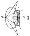
- FIG. 3is a sectional representation along the line A-A from FIG. 2 ;
- FIG. 4shows a sectional representation of an optical system including a visual means mounted therein according to a preferred embodiment of the invention
- FIG. 5shows a side view of a front area of an endoscope equipped with the visual means according to the invention in accordance with a second preferred embodiment of the invention.
- FIGS. 6 a and 6 bshow a sectional representation as well as the front view of an optical system according to the second preferred embodiment of the invention.
- the endoscopeis constructed of an endoscope shaft (not shown) and an endoscope head 1 arranged at the same, wherein a front area thereof is illustrated in FIG. 1 .
- the endoscopein the form of a probe or a capsule (without a shaft protruding from the body cavity) in which the visual means according to the invention is preferably accommodated in a front area of the capsule.
- the visual means according to the inventionin the present case consists of four optical systems 2 each of which comprises a lens unit 3 - 6 and a photosensitive element 7 or microchip arranged beneath the lens unit.
- the visual means according to the inventionin the present case consists of four optical systems 2 each of which comprises a lens unit 3 - 6 and a photosensitive element 7 or microchip arranged beneath the lens unit.
- only two or three optical systems 2 of this typecan be arranged.
- each of the represented optical systemscould be replaced with a plurality of smaller optical systems which are coupled to each other and whose field of vision corresponds at least to that of either of the represented optical systems.
- each of the optical systems shown in FIG. 1is designed as a zoom lens.
- a zoom lensconsists of a substantially tubular lens cylinder 8 .
- This cylinderis either integrally connected to the leading end of the shown endoscope shaft 1 or is detachably mounted in the same.
- the lens cylinder 8accommodates three lens units 3 - 5 in the present embodiment.
- the first lens unit 3consists of a lens 9 which is fixed at the outermost end of the lens cylinder 8 in the same perpendicularly to the center line of the lens cylinder 8 and in a fluid-tight manner.
- Each of the second and third lens units 4 , 5is arranged substantially circularly and perpendicularly to the center line of the lens cylinder 8 .
- Each of themconsists of a lens 10 , 11 , a lens mount 12 , 13 in which the respective lens 10 , 11 is fixed and a sealing ring 14 , 15 enclosing the respective lens mount 12 , 13 .
- the outside diameters of the lens mounts 12 , 13are minimally smaller than the inside diameter of the lens cylinder 8 so that the lens mounts 12 , 13 are movable in the axial direction of the lens cylinder 8 .
- the sealing rings 14 , 15seal between the peripheral outer surfaces of the respective lens mounts 12 , 13 and the inner surface of the lens cylinder 8 so that fluid-tight fluid chambers 16 - 18 are formed between the lens units 3 - 6 .
- the rear opening of the lens cylinderis closed in a fluid-tight manner by a further fourth fixed lens unit 6 .
- the fourth lens unit 6has on its face a central concave trough through which the light bundled by the lenses 9 - 11 is diffracted and transmitted to the optical sensor chip 7 .
- the rear half of the lens unit 6has a cubic shape, wherein the side lengths thereof in the plane perpendicular to the longitudinal axis of the lens cylinder 8 are adapted to the size of the optical sensor chip 7 .
- This optical sensor chip 7is arranged with its photosensitive side at the rear side of the lens unit 6 and converts visual information into electric signals.
- the optical sensor chip 7is mounted on its side opposite to the lens cylinder 8 on a functional carrier 19 which in turn is adapted to be fixed inside the front area of the endoscope.
- a spring which is likewise not shown in detailis inserted in each fluid chamber, which spring in the present embodiment is a spiral spring and is arranged so that the longitudinal axis thereof coincides with the longitudinal axis of the lens cylinder 8 .
- the outside diameter of the springsis minimally smaller than the inside diameter of the lens cylinder 8 so that the motions of the springs are not decelerated or blocked when they are compressed or expand.
- the ends of the respective springsare supported at the lens units 3 - 6 and form an annular bearing surface with the same.
- These springscan be biased in a desired way so as to position the adjustable lens units 4 , 5 in a home or constructional position.
- An assembly of the objectiveis facilitated by the fact that the springs space two adjacent lens units 3 - 6 from each other so that the sensitive lenses 9 - 11 cannot contact each other when no fluid is filled into the fluid chambers 16 - 18 yet.
- the springsensure a uniform axial movement by their uniform pressing in the plane perpendicular to the longitudinal axis of the lens cylinder 8 against the lens units 3 - 6 and thus prevent the lens units 3 - 6 from tilting or jamming in the lens cylinder 8 during movement.
- each fluid passage 20 - 22a cylinder (not shown) is connected in which a piston is inserted to slide therein and thus an actuator chamber communicated with the fluid chamber via the respective fluid conduit is delimited.
- Each of the fluid chambers 16 - 18 , of the fluid conduits 20 - 22 and of the actuator chambersis filled with an incompressible fluid which has the property of influencing the light transmission between the lens units as little as possible due to its presence between the lens units.
- the four optical systems 2 shown thereare distributed at equal angular distances from each other in a circumferential direction of the endoscope and are directed obliquely to the outside.
- the inclined angle in the present embodimentis 45° with respect to a longitudinal axis of the endoscope, whereas the aperture angle of each optical system is fixed to be 140°. In this way, a field of vision is resulting for each of the optical systems 2 which extends beyond the normal to the direction of movement to the rear as well as ahead beyond the longitudinal axis. As one can recognize especially from FIG.
- the fields of visionoverlap in the front area of the endoscope so that over a particular spherical segment 23 around the endoscope a closed visual scanning field is formed which extends in the form of a divided circle to the rear along the normal to the direction of movement of the endoscope in the area of the four optical systems.
- the functional carrier 19 on which the optical systems 2 are mountedis preferably in the form of a square truncated pyramid in the center of which further preferably a working duct is provided.
- Each optical system 2is connected to an image processing station.
- the endoscopeis a conventional design including an endoscope shaft or a probe or capsule design separated from the inlet/outlet of the body cavity to be examined, the aforementioned connection is made by means of electrically or light conducting cables or via radio.
- the image processing stationincludes a computer having an output device such as, for instance, a monitor and/or an image forming means.
- the image processingis performed via conventional image processing programs which have been available in prior art for some time already by means of which a total image can be formed from the simultaneous single pick-ups of the optical systems used.
- the endoscopes having a shaftinclude at their distal end a deflecting as it is called (this is a bendable finger at the free end of which the endoscope head 1 is arranged) which is manually bent via the endoscope shaft in order to be adapted to the individual canal bends. Consequently, it is necessary that the view ahead, i.e. in the direction of movement is constantly given.
- the canal wallshave to be inspected for anomalies without a bending movement of the deflecting becoming necessary to this end.
- the visual means according to the inventionby the fact that the image signals of the individual optical systems 2 are composed by the digital image processing station so as to form a panoramic image on which, in addition to the view ahead, a 360° all-round/panoramic view with respect to the direction of movement as well as the view obliquely to the rear is shown. In this way it is almost excluded that anomalies are missed.
- a total of four optical systemsis shown which are arranged at predetermined angular distances from each other.
- more or fewer optical systemscan be provided, of course.
- it/theycan be rotatably pivoted.
- the above-described truncated cone of the preferred embodimentcould be pivoted so that the one or two optical system(s) arranged on the surface area of the truncated cone run(s) along an orbit at a predetermined velocity and thus take up a 360° panoramic view.
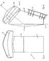
- FIGS. 5 and 6 a to 6 bnow a second preferred embodiment of the invention is shown.
- an endoscope head of the second preferred embodimentincludes a working duct 24 which opens at a front section of the endoscope head 25 .
- a working duct 24Around the working duct 24 at least two, however preferably three optical systems 2 each consisting of a photosensitive element 7 such as a microchip or a photoconductor cable and of a lens system are arranged and mounted on a carrier plate 19 .
- a photosensitive element 7such as a microchip or a photoconductor cable and of a lens system
- each optical system 2includes a photosensitive microchip 7 which is fixed in a substantially vertical alignment or an alignment inclined at an acute angle with respect to the normal V to a prism 26 whose one side opposite to the chip 7 forms an optical reflection surface 27 .
- this sideis vaporized to the inside.
- the prism 26furthermore has a light incidence side formed by an optically active surface 28 , where appropriate, which is outwardly inclined at a particular (preferably acute) angle likewise with respect to the normal V such that the light incidence extends obliquely from above to the optically active surface 28 .
- the free shape lens 29is arranged ahead of the light incidence side 28 of the prism 26 .
- free shape lensesare known from prior art, as they are used for instance in motor vehicle headlights for the diffraction of emitted light.
- the free shape lens 29is designed according to the invention such that the visual cone to be attained hereby is not symmetrical, i.e. circular in cross-section, but covers a cross-sectional area which is different from the circular form.
- This cross-sectional shapeis dependent on the number of optical systems 2 and thus on their angular distance from each other as well as on the inclination and/or the light incidence angle with respect to the normal V which is defined by the shape of the prism 26 .
- the free shape lens 29is shaped by analysis or by way of computing models known in prior art such that the angle of vision to be attained by the optical system 2 exceeds the normal to the length of the endoscope to the rear over an as large circumferential angle as possible with respect to the endoscope head 25 .
- the free shape lens 29is shaped in such a way that the angle of vision exceeding the normal to the endoscope axis to the rear is not formed as segment of a circle as in the case of a simple (circular) visual cone according to FIG. 1 , but it has an elliptical shape.
- the substantially triangular dead rangesstill clearly visible in FIG. 1 of the overlapping fields of vision of the individual optical systems are reduced, if at all, to small spots T which are practically insignificant in medical examinations.
Landscapes
- Physics & Mathematics (AREA)
- Astronomy & Astrophysics (AREA)
- General Physics & Mathematics (AREA)
- Optics & Photonics (AREA)
- Endoscopes (AREA)
- Instruments For Viewing The Inside Of Hollow Bodies (AREA)
Abstract
Description
Claims (15)
Applications Claiming Priority (3)
| Application Number | Priority Date | Filing Date | Title |
|---|---|---|---|
| DE102004026004ADE102004026004B4 (en) | 2004-05-27 | 2004-05-27 | Endoscope with visual device for all-round view |
| DE102004026004 | 2004-05-27 | ||
| DE102004026004.4 | 2004-05-27 |
Publications (2)
| Publication Number | Publication Date |
|---|---|
| US20050272979A1 US20050272979A1 (en) | 2005-12-08 |
| US7699772B2true US7699772B2 (en) | 2010-04-20 |
Family
ID=34933976
Family Applications (1)
| Application Number | Title | Priority Date | Filing Date |
|---|---|---|---|
| US11/137,067Active2028-07-10US7699772B2 (en) | 2004-05-27 | 2005-05-25 | Visual means of an endoscope |
Country Status (4)
| Country | Link |
|---|---|
| US (1) | US7699772B2 (en) |
| EP (1) | EP1600804A1 (en) |
| JP (1) | JP2005334647A (en) |
| DE (1) | DE102004026004B4 (en) |
Cited By (84)
| Publication number | Priority date | Publication date | Assignee | Title |
|---|---|---|---|---|
| US8926502B2 (en) | 2011-03-07 | 2015-01-06 | Endochoice, Inc. | Multi camera endoscope having a side service channel |
| US9101268B2 (en) | 2009-06-18 | 2015-08-11 | Endochoice Innovation Center Ltd. | Multi-camera endoscope |
| US9101266B2 (en) | 2011-02-07 | 2015-08-11 | Endochoice Innovation Center Ltd. | Multi-element cover for a multi-camera endoscope |
| US9101287B2 (en) | 2011-03-07 | 2015-08-11 | Endochoice Innovation Center Ltd. | Multi camera endoscope assembly having multiple working channels |
| US9314147B2 (en) | 2011-12-13 | 2016-04-19 | Endochoice Innovation Center Ltd. | Rotatable connector for an endoscope |
| US9320419B2 (en) | 2010-12-09 | 2016-04-26 | Endochoice Innovation Center Ltd. | Fluid channeling component of a multi-camera endoscope |
| US9402533B2 (en) | 2011-03-07 | 2016-08-02 | Endochoice Innovation Center Ltd. | Endoscope circuit board assembly |
| US9492063B2 (en) | 2009-06-18 | 2016-11-15 | Endochoice Innovation Center Ltd. | Multi-viewing element endoscope |
| US9554692B2 (en) | 2009-06-18 | 2017-01-31 | EndoChoice Innovation Ctr. Ltd. | Multi-camera endoscope |
| US9560953B2 (en) | 2010-09-20 | 2017-02-07 | Endochoice, Inc. | Operational interface in a multi-viewing element endoscope |
| US9560954B2 (en) | 2012-07-24 | 2017-02-07 | Endochoice, Inc. | Connector for use with endoscope |
| US9642513B2 (en) | 2009-06-18 | 2017-05-09 | Endochoice Inc. | Compact multi-viewing element endoscope system |
| US9655502B2 (en) | 2011-12-13 | 2017-05-23 | EndoChoice Innovation Center, Ltd. | Removable tip endoscope |
| US9706903B2 (en) | 2009-06-18 | 2017-07-18 | Endochoice, Inc. | Multiple viewing elements endoscope system with modular imaging units |
| US9713417B2 (en) | 2009-06-18 | 2017-07-25 | Endochoice, Inc. | Image capture assembly for use in a multi-viewing elements endoscope |
| US9814374B2 (en) | 2010-12-09 | 2017-11-14 | Endochoice Innovation Center Ltd. | Flexible electronic circuit board for a multi-camera endoscope |
| US9872609B2 (en) | 2009-06-18 | 2018-01-23 | Endochoice Innovation Center Ltd. | Multi-camera endoscope |
| US9901244B2 (en) | 2009-06-18 | 2018-02-27 | Endochoice, Inc. | Circuit board assembly of a multiple viewing elements endoscope |
| US9986899B2 (en) | 2013-03-28 | 2018-06-05 | Endochoice, Inc. | Manifold for a multiple viewing elements endoscope |
| US9993142B2 (en) | 2013-03-28 | 2018-06-12 | Endochoice, Inc. | Fluid distribution device for a multiple viewing elements endoscope |
| US10080486B2 (en) | 2010-09-20 | 2018-09-25 | Endochoice Innovation Center Ltd. | Multi-camera endoscope having fluid channels |
| US10165929B2 (en) | 2009-06-18 | 2019-01-01 | Endochoice, Inc. | Compact multi-viewing element endoscope system |
| US10203493B2 (en) | 2010-10-28 | 2019-02-12 | Endochoice Innovation Center Ltd. | Optical systems for multi-sensor endoscopes |
| US10499794B2 (en) | 2013-05-09 | 2019-12-10 | Endochoice, Inc. | Operational interface in a multi-viewing element endoscope |
| US11278190B2 (en) | 2009-06-18 | 2022-03-22 | Endochoice, Inc. | Multi-viewing element endoscope |
| US11547275B2 (en) | 2009-06-18 | 2023-01-10 | Endochoice, Inc. | Compact multi-viewing element endoscope system |
| US11701139B2 (en) | 2018-03-08 | 2023-07-18 | Cilag Gmbh International | Methods for controlling temperature in ultrasonic device |
| US11701185B2 (en) | 2017-12-28 | 2023-07-18 | Cilag Gmbh International | Wireless pairing of a surgical device with another device within a sterile surgical field based on the usage and situational awareness of devices |
| US11744604B2 (en) | 2017-12-28 | 2023-09-05 | Cilag Gmbh International | Surgical instrument with a hardware-only control circuit |
| US11751958B2 (en) | 2017-12-28 | 2023-09-12 | Cilag Gmbh International | Surgical hub coordination of control and communication of operating room devices |
| US11775682B2 (en) | 2017-12-28 | 2023-10-03 | Cilag Gmbh International | Data stripping method to interrogate patient records and create anonymized record |
| US11771487B2 (en) | 2017-12-28 | 2023-10-03 | Cilag Gmbh International | Mechanisms for controlling different electromechanical systems of an electrosurgical instrument |
| US11779337B2 (en) | 2017-12-28 | 2023-10-10 | Cilag Gmbh International | Method of using reinforced flexible circuits with multiple sensors to optimize performance of radio frequency devices |
| US11786251B2 (en) | 2017-12-28 | 2023-10-17 | Cilag Gmbh International | Method for adaptive control schemes for surgical network control and interaction |
| US11793537B2 (en) | 2017-10-30 | 2023-10-24 | Cilag Gmbh International | Surgical instrument comprising an adaptive electrical system |
| US11801098B2 (en) | 2017-10-30 | 2023-10-31 | Cilag Gmbh International | Method of hub communication with surgical instrument systems |
| US11818052B2 (en) | 2017-12-28 | 2023-11-14 | Cilag Gmbh International | Surgical network determination of prioritization of communication, interaction, or processing based on system or device needs |
| US11832899B2 (en) | 2017-12-28 | 2023-12-05 | Cilag Gmbh International | Surgical systems with autonomously adjustable control programs |
| US11839396B2 (en) | 2018-03-08 | 2023-12-12 | Cilag Gmbh International | Fine dissection mode for tissue classification |
| US11844579B2 (en) | 2017-12-28 | 2023-12-19 | Cilag Gmbh International | Adjustments based on airborne particle properties |
| US11857152B2 (en) | 2017-12-28 | 2024-01-02 | Cilag Gmbh International | Surgical hub spatial awareness to determine devices in operating theater |
| US11864845B2 (en) | 2017-12-28 | 2024-01-09 | Cilag Gmbh International | Sterile field interactive control displays |
| US11864728B2 (en) | 2017-12-28 | 2024-01-09 | Cilag Gmbh International | Characterization of tissue irregularities through the use of mono-chromatic light refractivity |
| US11864734B2 (en) | 2009-06-18 | 2024-01-09 | Endochoice, Inc. | Multi-camera endoscope |
| US11871901B2 (en) | 2012-05-20 | 2024-01-16 | Cilag Gmbh International | Method for situational awareness for surgical network or surgical network connected device capable of adjusting function based on a sensed situation or usage |
| US11889986B2 (en) | 2010-12-09 | 2024-02-06 | Endochoice, Inc. | Flexible electronic circuit board for a multi-camera endoscope |
| US11890065B2 (en) | 2017-12-28 | 2024-02-06 | Cilag Gmbh International | Surgical system to limit displacement |
| US11896443B2 (en) | 2017-12-28 | 2024-02-13 | Cilag Gmbh International | Control of a surgical system through a surgical barrier |
| US11896322B2 (en) | 2017-12-28 | 2024-02-13 | Cilag Gmbh International | Sensing the patient position and contact utilizing the mono-polar return pad electrode to provide situational awareness to the hub |
| US11903587B2 (en) | 2017-12-28 | 2024-02-20 | Cilag Gmbh International | Adjustment to the surgical stapling control based on situational awareness |
| US11911045B2 (en) | 2017-10-30 | 2024-02-27 | Cllag GmbH International | Method for operating a powered articulating multi-clip applier |
| US11925350B2 (en) | 2019-02-19 | 2024-03-12 | Cilag Gmbh International | Method for providing an authentication lockout in a surgical stapler with a replaceable cartridge |
| US11931027B2 (en) | 2018-03-28 | 2024-03-19 | Cilag Gmbh Interntional | Surgical instrument comprising an adaptive control system |
| US11969216B2 (en) | 2017-12-28 | 2024-04-30 | Cilag Gmbh International | Surgical network recommendations from real time analysis of procedure variables against a baseline highlighting differences from the optimal solution |
| US11969142B2 (en) | 2017-12-28 | 2024-04-30 | Cilag Gmbh International | Method of compressing tissue within a stapling device and simultaneously displaying the location of the tissue within the jaws |
| US11986233B2 (en) | 2018-03-08 | 2024-05-21 | Cilag Gmbh International | Adjustment of complex impedance to compensate for lost power in an articulating ultrasonic device |
| US11986185B2 (en) | 2018-03-28 | 2024-05-21 | Cilag Gmbh International | Methods for controlling a surgical stapler |
| US11998193B2 (en) | 2017-12-28 | 2024-06-04 | Cilag Gmbh International | Method for usage of the shroud as an aspect of sensing or controlling a powered surgical device, and a control algorithm to adjust its default operation |
| US12009095B2 (en) | 2017-12-28 | 2024-06-11 | Cilag Gmbh International | Real-time analysis of comprehensive cost of all instrumentation used in surgery utilizing data fluidity to track instruments through stocking and in-house processes |
| US12029506B2 (en) | 2017-12-28 | 2024-07-09 | Cilag Gmbh International | Method of cloud based data analytics for use with the hub |
| US12035983B2 (en) | 2017-10-30 | 2024-07-16 | Cilag Gmbh International | Method for producing a surgical instrument comprising a smart electrical system |
| US12035890B2 (en) | 2017-12-28 | 2024-07-16 | Cilag Gmbh International | Method of sensing particulate from smoke evacuated from a patient, adjusting the pump speed based on the sensed information, and communicating the functional parameters of the system to the hub |
| US12042207B2 (en) | 2017-12-28 | 2024-07-23 | Cilag Gmbh International | Estimating state of ultrasonic end effector and control system therefor |
| US12048496B2 (en) | 2017-12-28 | 2024-07-30 | Cilag Gmbh International | Adaptive control program updates for surgical hubs |
| US12062442B2 (en) | 2017-12-28 | 2024-08-13 | Cilag Gmbh International | Method for operating surgical instrument systems |
| US12059218B2 (en) | 2017-10-30 | 2024-08-13 | Cilag Gmbh International | Method of hub communication with surgical instrument systems |
| US12059169B2 (en) | 2017-12-28 | 2024-08-13 | Cilag Gmbh International | Controlling an ultrasonic surgical instrument according to tissue location |
| US12076010B2 (en) | 2017-12-28 | 2024-09-03 | Cilag Gmbh International | Surgical instrument cartridge sensor assemblies |
| US12127729B2 (en) | 2017-12-28 | 2024-10-29 | Cilag Gmbh International | Method for smoke evacuation for surgical hub |
| US12133709B2 (en) | 2017-12-28 | 2024-11-05 | Cilag Gmbh International | Communication hub and storage device for storing parameters and status of a surgical device to be shared with cloud based analytics systems |
| US12133773B2 (en) | 2017-12-28 | 2024-11-05 | Cilag Gmbh International | Surgical hub and modular device response adjustment based on situational awareness |
| US12137873B2 (en) | 2009-06-18 | 2024-11-12 | Endochoice, Inc. | Compact multi-viewing element endoscope system |
| US12144518B2 (en) | 2017-12-28 | 2024-11-19 | Cilag Gmbh International | Surgical systems for detecting end effector tissue distribution irregularities |
| US12204087B2 (en) | 2010-10-28 | 2025-01-21 | Endochoice, Inc. | Optical systems for multi-sensor endoscopes |
| US12207817B2 (en) | 2017-12-28 | 2025-01-28 | Cilag Gmbh International | Safety systems for smart powered surgical stapling |
| US12220105B2 (en) | 2010-06-16 | 2025-02-11 | Endochoice, Inc. | Circuit board assembly of a multiple viewing elements endoscope |
| US12226166B2 (en) | 2017-12-28 | 2025-02-18 | Cilag Gmbh International | Surgical instrument with a sensing array |
| US12226151B2 (en) | 2017-12-28 | 2025-02-18 | Cilag Gmbh International | Capacitive coupled return path pad with separable array elements |
| US12295674B2 (en) | 2017-12-28 | 2025-05-13 | Cilag Gmbh International | Usage and technique analysis of surgeon / staff performance against a baseline to optimize device utilization and performance for both current and future procedures |
| US12310586B2 (en) | 2017-12-28 | 2025-05-27 | Cilag Gmbh International | Method for adaptive control schemes for surgical network control and interaction |
| US12318152B2 (en) | 2017-12-28 | 2025-06-03 | Cilag Gmbh International | Computer implemented interactive surgical systems |
| US12329467B2 (en) | 2017-10-30 | 2025-06-17 | Cilag Gmbh International | Method of hub communication with surgical instrument systems |
| US12383115B2 (en) | 2017-12-28 | 2025-08-12 | Cilag Gmbh International | Method for smart energy device infrastructure |
| US12396806B2 (en) | 2017-12-28 | 2025-08-26 | Cilag Gmbh International | Adjustment of a surgical device function based on situational awareness |
Families Citing this family (14)
| Publication number | Priority date | Publication date | Assignee | Title |
|---|---|---|---|---|
| JP2005177025A (en)* | 2003-12-17 | 2005-07-07 | Olympus Corp | Endoscope |
| US8773500B2 (en) | 2006-01-18 | 2014-07-08 | Capso Vision, Inc. | In vivo image capturing system including capsule enclosing a camera |
| WO2007126429A2 (en)* | 2006-01-18 | 2007-11-08 | Capso Vision, Inc. | In vivo sensor with panoramic camera |
| JP4574596B2 (en)* | 2006-07-06 | 2010-11-04 | 富士フイルム株式会社 | Capsule endoscope |
| JP5492382B2 (en)* | 2008-02-19 | 2014-05-14 | 株式会社ビュープラス | Work surface photography camera |
| US8636653B2 (en) | 2008-06-09 | 2014-01-28 | Capso Vision, Inc. | In vivo camera with multiple sources to illuminate tissue at different distances |
| FR2977473B1 (en)* | 2011-07-08 | 2013-08-02 | Francois Duret | THREE-DIMENSIONAL MEASURING DEVICE USED IN THE DENTAL FIELD |
| FR2977469B1 (en)* | 2011-07-08 | 2013-08-02 | Francois Duret | THREE-DIMENSIONAL MEASURING DEVICE USED IN THE DENTAL FIELD |
| DE102011079068A1 (en) | 2011-07-13 | 2013-01-17 | Robert Bosch Gmbh | Method for focus adaptation with image capturing system i.e. high speed charge coupled device camera, of endoscope inspection device, involves determining focal region before or during recording about detection of component structure |
| DE102011079067A1 (en) | 2011-07-13 | 2013-01-17 | Robert Bosch Gmbh | Method for equalizing image of high-speed camera of endoscopic inspection device for e.g. inspecting hole-like openings in intestine, involves determining equalization of image in reference to scan-axis of testing body |
| KR102107402B1 (en)* | 2013-05-03 | 2020-05-07 | 삼성전자주식회사 | Endoscope and image processing apparatus using the endoscope |
| US20150080652A1 (en)* | 2013-09-18 | 2015-03-19 | Cerner Innovation, Inc. | Lesion detection and image stabilization using portion of field of view |
| US20190200906A1 (en)* | 2017-12-28 | 2019-07-04 | Ethicon Llc | Dual cmos array imaging |
| DE102018110523A1 (en)* | 2018-05-02 | 2019-11-07 | Karl Storz Se & Co. Kg | Endoscope and imaging device for an endoscope |
Citations (14)
| Publication number | Priority date | Publication date | Assignee | Title |
|---|---|---|---|---|
| AT244625B (en) | 1962-10-31 | 1966-01-10 | Contina Ag | Orthoscopic panorama optics with a straight view |
| US4204528A (en)* | 1977-03-10 | 1980-05-27 | Zafmedico Corp. | Method and apparatus for fiber-optic intravascular endoscopy |
| EP0305170A2 (en) | 1987-08-24 | 1989-03-01 | Allergan, Inc | Ophthalmic viewing instrument |
| US4838247A (en)* | 1988-10-06 | 1989-06-13 | Baxter International, Inc. | Dual-view arthroscope |
| US4947245A (en)* | 1988-05-23 | 1990-08-07 | Sumitomo Electric Industries, Ltd. | Image picking-up and processing apparatus |
| WO1995026674A1 (en) | 1994-03-30 | 1995-10-12 | Medical Media Systems | Electronically steerable endoscope |
| US5871440A (en)* | 1995-12-15 | 1999-02-16 | Olympus Optical Co., Ltd. | Endoscope |
| US5947958A (en)* | 1995-09-14 | 1999-09-07 | Conceptus, Inc. | Radiation-transmitting sheath and methods for its use |
| US6028719A (en) | 1998-10-02 | 2000-02-22 | Interscience, Inc. | 360 degree/forward view integral imaging system |
| US6306082B1 (en)* | 1994-03-17 | 2001-10-23 | Olympus Optical Co. | Stereoendoscope wherein images having passed through plural incident pupils are transmitted by common relay optical systems |
| DE10111354A1 (en) | 2001-03-08 | 2002-09-19 | Winter & Ibe Olympus | Endoscope instrument shaft sliding medium supply comes in through sourced channel in or grooved into shaft leading to shaft outlets and so onto outside surface of endoscope |
| US20030171648A1 (en)* | 2002-03-08 | 2003-09-11 | Takeshi Yokoi | Capsule endoscope |
| US6951536B2 (en)* | 2001-07-30 | 2005-10-04 | Olympus Corporation | Capsule-type medical device and medical system |
| US7108657B2 (en)* | 2001-03-30 | 2006-09-19 | Karl Storz Gmbh & Co. Kg | Endoscopic visualization apparatus with different imaging systems |
Family Cites Families (11)
| Publication number | Priority date | Publication date | Assignee | Title |
|---|---|---|---|---|
| US128A (en) | 1837-02-16 | Holdback for sleds | ||
| US5919A (en) | 1848-11-14 | Island | ||
| JPH04102432A (en)* | 1990-08-23 | 1992-04-03 | Olympus Optical Co Ltd | Endoscope |
| JPH04341232A (en)* | 1991-03-11 | 1992-11-27 | Olympus Optical Co Ltd | Electronic endoscope system |
| JP3441449B2 (en)* | 1991-03-11 | 2003-09-02 | オリンパス光学工業株式会社 | Endoscope device |
| JPH0739510A (en)* | 1993-07-28 | 1995-02-10 | Olympus Optical Co Ltd | Endoscope |
| JPH1043127A (en)* | 1996-08-02 | 1998-02-17 | Tsunehisa Shimoda | Medical endoscope |
| JPH10288742A (en)* | 1997-04-16 | 1998-10-27 | Olympus Optical Co Ltd | Endoscope device |
| US5919128A (en)* | 1997-06-18 | 1999-07-06 | The Regents Of The University Of California | Sparse aperture endoscope |
| JP3853931B2 (en)* | 1997-10-02 | 2006-12-06 | オリンパス株式会社 | Endoscope |
| US20020109774A1 (en)* | 2001-01-16 | 2002-08-15 | Gavriel Meron | System and method for wide field imaging of body lumens |
- 2004
- 2004-05-27DEDE102004026004Apatent/DE102004026004B4/ennot_activeExpired - Fee Related
- 2005
- 2005-02-28EPEP05004308Apatent/EP1600804A1/ennot_activeWithdrawn
- 2005-05-24JPJP2005151066Apatent/JP2005334647A/enactivePending
- 2005-05-25USUS11/137,067patent/US7699772B2/enactiveActive
Patent Citations (18)
| Publication number | Priority date | Publication date | Assignee | Title |
|---|---|---|---|---|
| AT244625B (en) | 1962-10-31 | 1966-01-10 | Contina Ag | Orthoscopic panorama optics with a straight view |
| US3404934A (en) | 1962-10-31 | 1968-10-08 | Brachvogel Heinz | Orthoscopic panoramic and straightview optical system |
| US4204528A (en)* | 1977-03-10 | 1980-05-27 | Zafmedico Corp. | Method and apparatus for fiber-optic intravascular endoscopy |
| EP0305170A2 (en) | 1987-08-24 | 1989-03-01 | Allergan, Inc | Ophthalmic viewing instrument |
| US4947245A (en)* | 1988-05-23 | 1990-08-07 | Sumitomo Electric Industries, Ltd. | Image picking-up and processing apparatus |
| US4838247A (en)* | 1988-10-06 | 1989-06-13 | Baxter International, Inc. | Dual-view arthroscope |
| US6306082B1 (en)* | 1994-03-17 | 2001-10-23 | Olympus Optical Co. | Stereoendoscope wherein images having passed through plural incident pupils are transmitted by common relay optical systems |
| US5800341A (en)* | 1994-03-30 | 1998-09-01 | Medical Media Systems | Electronically steerable endoscope |
| US5547455A (en) | 1994-03-30 | 1996-08-20 | Medical Media Systems | Electronically steerable endoscope |
| US6261226B1 (en)* | 1994-03-30 | 2001-07-17 | Medical Media Systems | Electronically Steerable Endoscope |
| WO1995026674A1 (en) | 1994-03-30 | 1995-10-12 | Medical Media Systems | Electronically steerable endoscope |
| US5947958A (en)* | 1995-09-14 | 1999-09-07 | Conceptus, Inc. | Radiation-transmitting sheath and methods for its use |
| US5871440A (en)* | 1995-12-15 | 1999-02-16 | Olympus Optical Co., Ltd. | Endoscope |
| US6028719A (en) | 1998-10-02 | 2000-02-22 | Interscience, Inc. | 360 degree/forward view integral imaging system |
| DE10111354A1 (en) | 2001-03-08 | 2002-09-19 | Winter & Ibe Olympus | Endoscope instrument shaft sliding medium supply comes in through sourced channel in or grooved into shaft leading to shaft outlets and so onto outside surface of endoscope |
| US7108657B2 (en)* | 2001-03-30 | 2006-09-19 | Karl Storz Gmbh & Co. Kg | Endoscopic visualization apparatus with different imaging systems |
| US6951536B2 (en)* | 2001-07-30 | 2005-10-04 | Olympus Corporation | Capsule-type medical device and medical system |
| US20030171648A1 (en)* | 2002-03-08 | 2003-09-11 | Takeshi Yokoi | Capsule endoscope |
Non-Patent Citations (2)
| Title |
|---|
| European Office Action, issued by the European Patent Office in connection with European application No. 05004308.2-1234, on Aug. 18, 2006, 3 pages. |
| European Search Report, issued by the European Patent Office in connection with European application No. 05004308.2-1234, on Aug. 22, 2005, 3 pages. |
Cited By (130)
| Publication number | Priority date | Publication date | Assignee | Title |
|---|---|---|---|---|
| US10912445B2 (en) | 2009-06-18 | 2021-02-09 | Endochoice, Inc. | Compact multi-viewing element endoscope system |
| US9713417B2 (en) | 2009-06-18 | 2017-07-25 | Endochoice, Inc. | Image capture assembly for use in a multi-viewing elements endoscope |
| US11864734B2 (en) | 2009-06-18 | 2024-01-09 | Endochoice, Inc. | Multi-camera endoscope |
| US11986155B2 (en) | 2009-06-18 | 2024-05-21 | Endochoice, Inc. | Multi-viewing element endoscope |
| US12137873B2 (en) | 2009-06-18 | 2024-11-12 | Endochoice, Inc. | Compact multi-viewing element endoscope system |
| US10765305B2 (en) | 2009-06-18 | 2020-09-08 | Endochoice, Inc. | Circuit board assembly of a multiple viewing elements endoscope |
| US10791910B2 (en) | 2009-06-18 | 2020-10-06 | Endochoice, Inc. | Multiple viewing elements endoscope system with modular imaging units |
| US12303106B2 (en) | 2009-06-18 | 2025-05-20 | Endochoice, Inc. | Multi-camera endoscope |
| US9492063B2 (en) | 2009-06-18 | 2016-11-15 | Endochoice Innovation Center Ltd. | Multi-viewing element endoscope |
| US9554692B2 (en) | 2009-06-18 | 2017-01-31 | EndoChoice Innovation Ctr. Ltd. | Multi-camera endoscope |
| US11534056B2 (en) | 2009-06-18 | 2022-12-27 | Endochoice, Inc. | Multi-camera endoscope |
| US12336686B2 (en) | 2009-06-18 | 2025-06-24 | Endochoice, Inc. | Multi-viewing element endoscope |
| US9642513B2 (en) | 2009-06-18 | 2017-05-09 | Endochoice Inc. | Compact multi-viewing element endoscope system |
| US11547275B2 (en) | 2009-06-18 | 2023-01-10 | Endochoice, Inc. | Compact multi-viewing element endoscope system |
| US9706905B2 (en) | 2009-06-18 | 2017-07-18 | Endochoice Innovation Center Ltd. | Multi-camera endoscope |
| US9706903B2 (en) | 2009-06-18 | 2017-07-18 | Endochoice, Inc. | Multiple viewing elements endoscope system with modular imaging units |
| US9101268B2 (en) | 2009-06-18 | 2015-08-11 | Endochoice Innovation Center Ltd. | Multi-camera endoscope |
| US10791909B2 (en) | 2009-06-18 | 2020-10-06 | Endochoice, Inc. | Image capture assembly for use in a multi-viewing elements endoscope |
| US10799095B2 (en) | 2009-06-18 | 2020-10-13 | Endochoice, Inc. | Multi-viewing element endoscope |
| US11471028B2 (en) | 2009-06-18 | 2022-10-18 | Endochoice, Inc. | Circuit board assembly of a multiple viewing elements endoscope |
| US9872609B2 (en) | 2009-06-18 | 2018-01-23 | Endochoice Innovation Center Ltd. | Multi-camera endoscope |
| US9901244B2 (en) | 2009-06-18 | 2018-02-27 | Endochoice, Inc. | Circuit board assembly of a multiple viewing elements endoscope |
| US11278190B2 (en) | 2009-06-18 | 2022-03-22 | Endochoice, Inc. | Multi-viewing element endoscope |
| US10165929B2 (en) | 2009-06-18 | 2019-01-01 | Endochoice, Inc. | Compact multi-viewing element endoscope system |
| US10638922B2 (en) | 2009-06-18 | 2020-05-05 | Endochoice, Inc. | Multi-camera endoscope |
| US10905320B2 (en) | 2009-06-18 | 2021-02-02 | Endochoice, Inc. | Multi-camera endoscope |
| US10092167B2 (en) | 2009-06-18 | 2018-10-09 | Endochoice, Inc. | Multiple viewing elements endoscope system with modular imaging units |
| US12220105B2 (en) | 2010-06-16 | 2025-02-11 | Endochoice, Inc. | Circuit board assembly of a multiple viewing elements endoscope |
| US10080486B2 (en) | 2010-09-20 | 2018-09-25 | Endochoice Innovation Center Ltd. | Multi-camera endoscope having fluid channels |
| US9986892B2 (en) | 2010-09-20 | 2018-06-05 | Endochoice, Inc. | Operational interface in a multi-viewing element endoscope |
| US9560953B2 (en) | 2010-09-20 | 2017-02-07 | Endochoice, Inc. | Operational interface in a multi-viewing element endoscope |
| US10203493B2 (en) | 2010-10-28 | 2019-02-12 | Endochoice Innovation Center Ltd. | Optical systems for multi-sensor endoscopes |
| US11543646B2 (en) | 2010-10-28 | 2023-01-03 | Endochoice, Inc. | Optical systems for multi-sensor endoscopes |
| US12204087B2 (en) | 2010-10-28 | 2025-01-21 | Endochoice, Inc. | Optical systems for multi-sensor endoscopes |
| US9814374B2 (en) | 2010-12-09 | 2017-11-14 | Endochoice Innovation Center Ltd. | Flexible electronic circuit board for a multi-camera endoscope |
| US9320419B2 (en) | 2010-12-09 | 2016-04-26 | Endochoice Innovation Center Ltd. | Fluid channeling component of a multi-camera endoscope |
| US10182707B2 (en) | 2010-12-09 | 2019-01-22 | Endochoice Innovation Center Ltd. | Fluid channeling component of a multi-camera endoscope |
| US10898063B2 (en) | 2010-12-09 | 2021-01-26 | Endochoice, Inc. | Flexible electronic circuit board for a multi camera endoscope |
| US11889986B2 (en) | 2010-12-09 | 2024-02-06 | Endochoice, Inc. | Flexible electronic circuit board for a multi-camera endoscope |
| US11497388B2 (en) | 2010-12-09 | 2022-11-15 | Endochoice, Inc. | Flexible electronic circuit board for a multi-camera endoscope |
| US9101266B2 (en) | 2011-02-07 | 2015-08-11 | Endochoice Innovation Center Ltd. | Multi-element cover for a multi-camera endoscope |
| US9351629B2 (en) | 2011-02-07 | 2016-05-31 | Endochoice Innovation Center Ltd. | Multi-element cover for a multi-camera endoscope |
| US10070774B2 (en) | 2011-02-07 | 2018-09-11 | Endochoice Innovation Center Ltd. | Multi-element cover for a multi-camera endoscope |
| US9713415B2 (en) | 2011-03-07 | 2017-07-25 | Endochoice Innovation Center Ltd. | Multi camera endoscope having a side service channel |
| US10292578B2 (en) | 2011-03-07 | 2019-05-21 | Endochoice Innovation Center Ltd. | Multi camera endoscope assembly having multiple working channels |
| US9402533B2 (en) | 2011-03-07 | 2016-08-02 | Endochoice Innovation Center Ltd. | Endoscope circuit board assembly |
| US11026566B2 (en) | 2011-03-07 | 2021-06-08 | Endochoice, Inc. | Multi camera endoscope assembly having multiple working channels |
| US9854959B2 (en) | 2011-03-07 | 2018-01-02 | Endochoice Innovation Center Ltd. | Multi camera endoscope assembly having multiple working channels |
| US9101287B2 (en) | 2011-03-07 | 2015-08-11 | Endochoice Innovation Center Ltd. | Multi camera endoscope assembly having multiple working channels |
| US8926502B2 (en) | 2011-03-07 | 2015-01-06 | Endochoice, Inc. | Multi camera endoscope having a side service channel |
| US11291357B2 (en) | 2011-12-13 | 2022-04-05 | Endochoice, Inc. | Removable tip endoscope |
| US9655502B2 (en) | 2011-12-13 | 2017-05-23 | EndoChoice Innovation Center, Ltd. | Removable tip endoscope |
| US9314147B2 (en) | 2011-12-13 | 2016-04-19 | Endochoice Innovation Center Ltd. | Rotatable connector for an endoscope |
| US12290241B2 (en) | 2011-12-13 | 2025-05-06 | Endochoice, Inc. | Removable tip endoscope |
| US10470649B2 (en) | 2011-12-13 | 2019-11-12 | Endochoice, Inc. | Removable tip endoscope |
| US11871901B2 (en) | 2012-05-20 | 2024-01-16 | Cilag Gmbh International | Method for situational awareness for surgical network or surgical network connected device capable of adjusting function based on a sensed situation or usage |
| US9560954B2 (en) | 2012-07-24 | 2017-02-07 | Endochoice, Inc. | Connector for use with endoscope |
| US9993142B2 (en) | 2013-03-28 | 2018-06-12 | Endochoice, Inc. | Fluid distribution device for a multiple viewing elements endoscope |
| US12232699B2 (en) | 2013-03-28 | 2025-02-25 | Endochoice, Inc. | Manifold for a multiple viewing elements endoscope |
| US9986899B2 (en) | 2013-03-28 | 2018-06-05 | Endochoice, Inc. | Manifold for a multiple viewing elements endoscope |
| US11793393B2 (en) | 2013-03-28 | 2023-10-24 | Endochoice, Inc. | Manifold for a multiple viewing elements endoscope |
| US10925471B2 (en) | 2013-03-28 | 2021-02-23 | Endochoice, Inc. | Fluid distribution device for a multiple viewing elements endoscope |
| US10905315B2 (en) | 2013-03-28 | 2021-02-02 | Endochoice, Inc. | Manifold for a multiple viewing elements endoscope |
| US11925323B2 (en) | 2013-03-28 | 2024-03-12 | Endochoice, Inc. | Fluid distribution device for a multiple viewing elements endoscope |
| US10499794B2 (en) | 2013-05-09 | 2019-12-10 | Endochoice, Inc. | Operational interface in a multi-viewing element endoscope |
| US12329467B2 (en) | 2017-10-30 | 2025-06-17 | Cilag Gmbh International | Method of hub communication with surgical instrument systems |
| US12059218B2 (en) | 2017-10-30 | 2024-08-13 | Cilag Gmbh International | Method of hub communication with surgical instrument systems |
| US12035983B2 (en) | 2017-10-30 | 2024-07-16 | Cilag Gmbh International | Method for producing a surgical instrument comprising a smart electrical system |
| US12121255B2 (en) | 2017-10-30 | 2024-10-22 | Cilag Gmbh International | Electrical power output control based on mechanical forces |
| US11925373B2 (en) | 2017-10-30 | 2024-03-12 | Cilag Gmbh International | Surgical suturing instrument comprising a non-circular needle |
| US11819231B2 (en) | 2017-10-30 | 2023-11-21 | Cilag Gmbh International | Adaptive control programs for a surgical system comprising more than one type of cartridge |
| US11911045B2 (en) | 2017-10-30 | 2024-02-27 | Cllag GmbH International | Method for operating a powered articulating multi-clip applier |
| US11801098B2 (en) | 2017-10-30 | 2023-10-31 | Cilag Gmbh International | Method of hub communication with surgical instrument systems |
| US11793537B2 (en) | 2017-10-30 | 2023-10-24 | Cilag Gmbh International | Surgical instrument comprising an adaptive electrical system |
| US11818052B2 (en) | 2017-12-28 | 2023-11-14 | Cilag Gmbh International | Surgical network determination of prioritization of communication, interaction, or processing based on system or device needs |
| US12207817B2 (en) | 2017-12-28 | 2025-01-28 | Cilag Gmbh International | Safety systems for smart powered surgical stapling |
| US11896443B2 (en) | 2017-12-28 | 2024-02-13 | Cilag Gmbh International | Control of a surgical system through a surgical barrier |
| US11896322B2 (en) | 2017-12-28 | 2024-02-13 | Cilag Gmbh International | Sensing the patient position and contact utilizing the mono-polar return pad electrode to provide situational awareness to the hub |
| US11903587B2 (en) | 2017-12-28 | 2024-02-20 | Cilag Gmbh International | Adjustment to the surgical stapling control based on situational awareness |
| US11864728B2 (en) | 2017-12-28 | 2024-01-09 | Cilag Gmbh International | Characterization of tissue irregularities through the use of mono-chromatic light refractivity |
| US11918302B2 (en) | 2017-12-28 | 2024-03-05 | Cilag Gmbh International | Sterile field interactive control displays |
| US11864845B2 (en) | 2017-12-28 | 2024-01-09 | Cilag Gmbh International | Sterile field interactive control displays |
| US12396806B2 (en) | 2017-12-28 | 2025-08-26 | Cilag Gmbh International | Adjustment of a surgical device function based on situational awareness |
| US11857152B2 (en) | 2017-12-28 | 2024-01-02 | Cilag Gmbh International | Surgical hub spatial awareness to determine devices in operating theater |
| US12383115B2 (en) | 2017-12-28 | 2025-08-12 | Cilag Gmbh International | Method for smart energy device infrastructure |
| US11969216B2 (en) | 2017-12-28 | 2024-04-30 | Cilag Gmbh International | Surgical network recommendations from real time analysis of procedure variables against a baseline highlighting differences from the optimal solution |
| US11969142B2 (en) | 2017-12-28 | 2024-04-30 | Cilag Gmbh International | Method of compressing tissue within a stapling device and simultaneously displaying the location of the tissue within the jaws |
| US11701185B2 (en) | 2017-12-28 | 2023-07-18 | Cilag Gmbh International | Wireless pairing of a surgical device with another device within a sterile surgical field based on the usage and situational awareness of devices |
| US12318152B2 (en) | 2017-12-28 | 2025-06-03 | Cilag Gmbh International | Computer implemented interactive surgical systems |
| US12310586B2 (en) | 2017-12-28 | 2025-05-27 | Cilag Gmbh International | Method for adaptive control schemes for surgical network control and interaction |
| US11998193B2 (en) | 2017-12-28 | 2024-06-04 | Cilag Gmbh International | Method for usage of the shroud as an aspect of sensing or controlling a powered surgical device, and a control algorithm to adjust its default operation |
| US12009095B2 (en) | 2017-12-28 | 2024-06-11 | Cilag Gmbh International | Real-time analysis of comprehensive cost of all instrumentation used in surgery utilizing data fluidity to track instruments through stocking and in-house processes |
| US12029506B2 (en) | 2017-12-28 | 2024-07-09 | Cilag Gmbh International | Method of cloud based data analytics for use with the hub |
| US11844579B2 (en) | 2017-12-28 | 2023-12-19 | Cilag Gmbh International | Adjustments based on airborne particle properties |
| US12035890B2 (en) | 2017-12-28 | 2024-07-16 | Cilag Gmbh International | Method of sensing particulate from smoke evacuated from a patient, adjusting the pump speed based on the sensed information, and communicating the functional parameters of the system to the hub |
| US12042207B2 (en) | 2017-12-28 | 2024-07-23 | Cilag Gmbh International | Estimating state of ultrasonic end effector and control system therefor |
| US12048496B2 (en) | 2017-12-28 | 2024-07-30 | Cilag Gmbh International | Adaptive control program updates for surgical hubs |
| US12053159B2 (en) | 2017-12-28 | 2024-08-06 | Cilag Gmbh International | Method of sensing particulate from smoke evacuated from a patient, adjusting the pump speed based on the sensed information, and communicating the functional parameters of the system to the hub |
| US12062442B2 (en) | 2017-12-28 | 2024-08-13 | Cilag Gmbh International | Method for operating surgical instrument systems |
| US12059124B2 (en) | 2017-12-28 | 2024-08-13 | Cilag Gmbh International | Surgical hub spatial awareness to determine devices in operating theater |
| US11744604B2 (en) | 2017-12-28 | 2023-09-05 | Cilag Gmbh International | Surgical instrument with a hardware-only control circuit |
| US12059169B2 (en) | 2017-12-28 | 2024-08-13 | Cilag Gmbh International | Controlling an ultrasonic surgical instrument according to tissue location |
| US12076010B2 (en) | 2017-12-28 | 2024-09-03 | Cilag Gmbh International | Surgical instrument cartridge sensor assemblies |
| US12096985B2 (en) | 2017-12-28 | 2024-09-24 | Cilag Gmbh International | Surgical network recommendations from real time analysis of procedure variables against a baseline highlighting differences from the optimal solution |
| US12096916B2 (en) | 2017-12-28 | 2024-09-24 | Cilag Gmbh International | Method of sensing particulate from smoke evacuated from a patient, adjusting the pump speed based on the sensed information, and communicating the functional parameters of the system to the hub |
| US12295674B2 (en) | 2017-12-28 | 2025-05-13 | Cilag Gmbh International | Usage and technique analysis of surgeon / staff performance against a baseline to optimize device utilization and performance for both current and future procedures |
| US11832899B2 (en) | 2017-12-28 | 2023-12-05 | Cilag Gmbh International | Surgical systems with autonomously adjustable control programs |
| US12127729B2 (en) | 2017-12-28 | 2024-10-29 | Cilag Gmbh International | Method for smoke evacuation for surgical hub |
| US12133709B2 (en) | 2017-12-28 | 2024-11-05 | Cilag Gmbh International | Communication hub and storage device for storing parameters and status of a surgical device to be shared with cloud based analytics systems |
| US12133773B2 (en) | 2017-12-28 | 2024-11-05 | Cilag Gmbh International | Surgical hub and modular device response adjustment based on situational awareness |
| US11786251B2 (en) | 2017-12-28 | 2023-10-17 | Cilag Gmbh International | Method for adaptive control schemes for surgical network control and interaction |
| US12144518B2 (en) | 2017-12-28 | 2024-11-19 | Cilag Gmbh International | Surgical systems for detecting end effector tissue distribution irregularities |
| US12193636B2 (en) | 2017-12-28 | 2025-01-14 | Cilag Gmbh International | Characterization of tissue irregularities through the use of mono-chromatic light refractivity |
| US11779337B2 (en) | 2017-12-28 | 2023-10-10 | Cilag Gmbh International | Method of using reinforced flexible circuits with multiple sensors to optimize performance of radio frequency devices |
| US11890065B2 (en) | 2017-12-28 | 2024-02-06 | Cilag Gmbh International | Surgical system to limit displacement |
| US11771487B2 (en) | 2017-12-28 | 2023-10-03 | Cilag Gmbh International | Mechanisms for controlling different electromechanical systems of an electrosurgical instrument |
| US12226166B2 (en) | 2017-12-28 | 2025-02-18 | Cilag Gmbh International | Surgical instrument with a sensing array |
| US12226151B2 (en) | 2017-12-28 | 2025-02-18 | Cilag Gmbh International | Capacitive coupled return path pad with separable array elements |
| US11775682B2 (en) | 2017-12-28 | 2023-10-03 | Cilag Gmbh International | Data stripping method to interrogate patient records and create anonymized record |
| US12239320B2 (en) | 2017-12-28 | 2025-03-04 | Cilag Gmbh International | Method of using reinforced flexible circuits with multiple sensors to optimize performance of radio frequency devices |
| US12256995B2 (en) | 2017-12-28 | 2025-03-25 | Cilag Gmbh International | Surgical network recommendations from real time analysis of procedure variables against a baseline highlighting differences from the optimal solution |
| US11751958B2 (en) | 2017-12-28 | 2023-09-12 | Cilag Gmbh International | Surgical hub coordination of control and communication of operating room devices |
| US12121256B2 (en) | 2018-03-08 | 2024-10-22 | Cilag Gmbh International | Methods for controlling temperature in ultrasonic device |
| US11839396B2 (en) | 2018-03-08 | 2023-12-12 | Cilag Gmbh International | Fine dissection mode for tissue classification |
| US11844545B2 (en) | 2018-03-08 | 2023-12-19 | Cilag Gmbh International | Calcified vessel identification |
| US11986233B2 (en) | 2018-03-08 | 2024-05-21 | Cilag Gmbh International | Adjustment of complex impedance to compensate for lost power in an articulating ultrasonic device |
| US11701139B2 (en) | 2018-03-08 | 2023-07-18 | Cilag Gmbh International | Methods for controlling temperature in ultrasonic device |
| US11986185B2 (en) | 2018-03-28 | 2024-05-21 | Cilag Gmbh International | Methods for controlling a surgical stapler |
| US11931027B2 (en) | 2018-03-28 | 2024-03-19 | Cilag Gmbh Interntional | Surgical instrument comprising an adaptive control system |
| US11925350B2 (en) | 2019-02-19 | 2024-03-12 | Cilag Gmbh International | Method for providing an authentication lockout in a surgical stapler with a replaceable cartridge |
Also Published As
| Publication number | Publication date |
|---|---|
| DE102004026004B4 (en) | 2006-09-21 |
| EP1600804A1 (en) | 2005-11-30 |
| JP2005334647A (en) | 2005-12-08 |
| DE102004026004A1 (en) | 2005-12-22 |
| US20050272979A1 (en) | 2005-12-08 |
Similar Documents
| Publication | Publication Date | Title |
|---|---|---|
| US7699772B2 (en) | Visual means of an endoscope | |
| US5800341A (en) | Electronically steerable endoscope | |
| US10536617B2 (en) | Dual-view probe for illumination and imaging, and use thereof | |
| CN105581766B (en) | Adapter for endoscope | |
| EP1620012B1 (en) | Panoramic field of view imaging device | |
| EP1686410B1 (en) | Optical system for variable direction of view instrument | |
| JP4779120B2 (en) | Endoscope attachment and endoscope | |
| US20060217593A1 (en) | Device, system and method of panoramic multiple field of view imaging | |
| EP2244626B1 (en) | Radial scanner imaging system | |
| WO2009014895A1 (en) | Endoscope assembly and method of viewing an area inside a cavity | |
| US12105402B2 (en) | Optical imaging system and operation thereof | |
| AU2023237088B2 (en) | Optical, optoelectronic, and optoelectromechanical systems and method for using the same | |
| JP5548145B2 (en) | All-around observation optical system and all-around observation system including the same | |
| US20120035420A1 (en) | Endoscope with adjustable viewing angle | |
| TWM535060U (en) | Panoramic endoscope device | |
| CN217244290U (en) | Objective lens module, endoscope and endoscope imaging equipment | |
| JPH11109257A (en) | Image pickup optical system of endoscope | |
| CN216387574U (en) | Endoscope imaging system based on liquid zoom lens and endoscope | |
| JPH08201706A (en) | Endoscope device | |
| WO2025074354A1 (en) | Combined catadioptric optical system with 360 degree forward and panoramic vision for medical imaging | |
| Fair et al. | Panoramic endoscopy | |
| TWI607734B (en) | Panoramic endoscope device | |
| CN113933986A (en) | Endoscope imaging system based on liquid zoom lens and endoscope | |
| CN116407060A (en) | Objective lens module, endoscope and endoscope imaging device | |
| CN118576127A (en) | System and method for viewing capsule images with interest detection regions |
Legal Events
| Date | Code | Title | Description |
|---|---|---|---|
| AS | Assignment | Owner name:STM MEDIZINTECHNIK STARNBERG GMBH,GERMANY Free format text:ASSIGNMENT OF ASSIGNORS INTEREST;ASSIGNORS:PAUKER, FRITZ;VIEHBACH, THOMAS;BOB, DR. KONSTANTIN;SIGNING DATES FROM 20050720 TO 20050721;REEL/FRAME:016894/0714 Owner name:STM MEDIZINTECHNIK STARNBERG GMBH, GERMANY Free format text:ASSIGNMENT OF ASSIGNORS INTEREST;ASSIGNORS:PAUKER, FRITZ;VIEHBACH, THOMAS;BOB, DR. KONSTANTIN;REEL/FRAME:016894/0714;SIGNING DATES FROM 20050720 TO 20050721 | |
| STCF | Information on status: patent grant | Free format text:PATENTED CASE | |
| FEPP | Fee payment procedure | Free format text:PAYOR NUMBER ASSIGNED (ORIGINAL EVENT CODE: ASPN); ENTITY STATUS OF PATENT OWNER: LARGE ENTITY | |
| FPAY | Fee payment | Year of fee payment:4 | |
| FEPP | Fee payment procedure | Free format text:ENTITY STATUS SET TO UNDISCOUNTED (ORIGINAL EVENT CODE: BIG.) | |
| MAFP | Maintenance fee payment | Free format text:PAYMENT OF MAINTENANCE FEE, 8TH YEAR, LARGE ENTITY (ORIGINAL EVENT CODE: M1552) Year of fee payment:8 | |
| AS | Assignment | Owner name:STM MEDIZINTECHNIK GMBH, GERMANY Free format text:CHANGE OF NAME;ASSIGNOR:STM MEDIZINTECHNIK STARNBERG GMBH;REEL/FRAME:044697/0320 Effective date:20040724 Owner name:INVENDO MEDICAL GMBH, GERMANY Free format text:CHANGE OF NAME;ASSIGNOR:STM MEDIZINTECHNIK GMBH;REEL/FRAME:044697/0875 Effective date:20060213 | |
| MAFP | Maintenance fee payment | Free format text:PAYMENT OF MAINTENANCE FEE, 12TH YEAR, LARGE ENTITY (ORIGINAL EVENT CODE: M1553); ENTITY STATUS OF PATENT OWNER: LARGE ENTITY Year of fee payment:12 |