US7699755B2 - Isometric exercise system and method of facilitating user exercise during video game play - Google Patents
Isometric exercise system and method of facilitating user exercise during video game playDownload PDFInfo
- Publication number
- US7699755B2 US7699755B2US11/350,284US35028406AUS7699755B2US 7699755 B2US7699755 B2US 7699755B2US 35028406 AUS35028406 AUS 35028406AUS 7699755 B2US7699755 B2US 7699755B2
- Authority
- US
- United States
- Prior art keywords
- user
- effector
- controller
- exercise
- base
- Prior art date
- Legal status (The legal status is an assumption and is not a legal conclusion. Google has not performed a legal analysis and makes no representation as to the accuracy of the status listed.)
- Expired - Fee Related, expires
Links
Images


Classifications
- A—HUMAN NECESSITIES
- A63—SPORTS; GAMES; AMUSEMENTS
- A63F—CARD, BOARD, OR ROULETTE GAMES; INDOOR GAMES USING SMALL MOVING PLAYING BODIES; VIDEO GAMES; GAMES NOT OTHERWISE PROVIDED FOR
- A63F13/00—Video games, i.e. games using an electronically generated display having two or more dimensions
- A63F13/80—Special adaptations for executing a specific game genre or game mode
- A—HUMAN NECESSITIES
- A63—SPORTS; GAMES; AMUSEMENTS
- A63B—APPARATUS FOR PHYSICAL TRAINING, GYMNASTICS, SWIMMING, CLIMBING, OR FENCING; BALL GAMES; TRAINING EQUIPMENT
- A63B21/00—Exercising apparatus for developing or strengthening the muscles or joints of the body by working against a counterforce, with or without measuring devices
- A63B21/002—Exercising apparatus for developing or strengthening the muscles or joints of the body by working against a counterforce, with or without measuring devices isometric or isokinetic, i.e. substantial force variation without substantial muscle motion or wherein the speed of the motion is independent of the force applied by the user
- A—HUMAN NECESSITIES
- A63—SPORTS; GAMES; AMUSEMENTS
- A63B—APPARATUS FOR PHYSICAL TRAINING, GYMNASTICS, SWIMMING, CLIMBING, OR FENCING; BALL GAMES; TRAINING EQUIPMENT
- A63B24/00—Electric or electronic controls for exercising apparatus of preceding groups; Controlling or monitoring of exercises, sportive games, training or athletic performances
- A—HUMAN NECESSITIES
- A63—SPORTS; GAMES; AMUSEMENTS
- A63B—APPARATUS FOR PHYSICAL TRAINING, GYMNASTICS, SWIMMING, CLIMBING, OR FENCING; BALL GAMES; TRAINING EQUIPMENT
- A63B71/00—Games or sports accessories not covered in groups A63B1/00 - A63B69/00
- A63B71/0009—Games or sports accessories not covered in groups A63B1/00 - A63B69/00 for handicapped persons
- A—HUMAN NECESSITIES
- A63—SPORTS; GAMES; AMUSEMENTS
- A63B—APPARATUS FOR PHYSICAL TRAINING, GYMNASTICS, SWIMMING, CLIMBING, OR FENCING; BALL GAMES; TRAINING EQUIPMENT
- A63B71/00—Games or sports accessories not covered in groups A63B1/00 - A63B69/00
- A63B71/06—Indicating or scoring devices for games or players, or for other sports activities
- A63B71/0619—Displays, user interfaces and indicating devices, specially adapted for sport equipment, e.g. display mounted on treadmills
- A63B71/0622—Visual, audio or audio-visual systems for entertaining, instructing or motivating the user
- A—HUMAN NECESSITIES
- A63—SPORTS; GAMES; AMUSEMENTS
- A63F—CARD, BOARD, OR ROULETTE GAMES; INDOOR GAMES USING SMALL MOVING PLAYING BODIES; VIDEO GAMES; GAMES NOT OTHERWISE PROVIDED FOR
- A63F13/00—Video games, i.e. games using an electronically generated display having two or more dimensions
- A63F13/20—Input arrangements for video game devices
- A63F13/21—Input arrangements for video game devices characterised by their sensors, purposes or types
- A63F13/218—Input arrangements for video game devices characterised by their sensors, purposes or types using pressure sensors, e.g. generating a signal proportional to the pressure applied by the player
- A—HUMAN NECESSITIES
- A63—SPORTS; GAMES; AMUSEMENTS
- A63F—CARD, BOARD, OR ROULETTE GAMES; INDOOR GAMES USING SMALL MOVING PLAYING BODIES; VIDEO GAMES; GAMES NOT OTHERWISE PROVIDED FOR
- A63F13/00—Video games, i.e. games using an electronically generated display having two or more dimensions
- A63F13/20—Input arrangements for video game devices
- A63F13/24—Constructional details thereof, e.g. game controllers with detachable joystick handles
- A63F13/245—Constructional details thereof, e.g. game controllers with detachable joystick handles specially adapted to a particular type of game, e.g. steering wheels
- A—HUMAN NECESSITIES
- A63—SPORTS; GAMES; AMUSEMENTS
- A63F—CARD, BOARD, OR ROULETTE GAMES; INDOOR GAMES USING SMALL MOVING PLAYING BODIES; VIDEO GAMES; GAMES NOT OTHERWISE PROVIDED FOR
- A63F13/00—Video games, i.e. games using an electronically generated display having two or more dimensions
- A63F13/45—Controlling the progress of the video game
- A63F13/47—Controlling the progress of the video game involving branching, e.g. choosing one of several possible scenarios at a given point in time
- A—HUMAN NECESSITIES
- A63—SPORTS; GAMES; AMUSEMENTS
- A63F—CARD, BOARD, OR ROULETTE GAMES; INDOOR GAMES USING SMALL MOVING PLAYING BODIES; VIDEO GAMES; GAMES NOT OTHERWISE PROVIDED FOR
- A63F13/00—Video games, i.e. games using an electronically generated display having two or more dimensions
- A63F13/55—Controlling game characters or game objects based on the game progress
- A63F13/57—Simulating properties, behaviour or motion of objects in the game world, e.g. computing tyre load in a car race game
- A—HUMAN NECESSITIES
- A63—SPORTS; GAMES; AMUSEMENTS
- A63F—CARD, BOARD, OR ROULETTE GAMES; INDOOR GAMES USING SMALL MOVING PLAYING BODIES; VIDEO GAMES; GAMES NOT OTHERWISE PROVIDED FOR
- A63F13/00—Video games, i.e. games using an electronically generated display having two or more dimensions
- A63F13/90—Constructional details or arrangements of video game devices not provided for in groups A63F13/20 or A63F13/25, e.g. housing, wiring, connections or cabinets
- A63F13/98—Accessories, i.e. detachable arrangements optional for the use of the video game device, e.g. grip supports of game controllers
- A—HUMAN NECESSITIES
- A63—SPORTS; GAMES; AMUSEMENTS
- A63B—APPARATUS FOR PHYSICAL TRAINING, GYMNASTICS, SWIMMING, CLIMBING, OR FENCING; BALL GAMES; TRAINING EQUIPMENT
- A63B71/00—Games or sports accessories not covered in groups A63B1/00 - A63B69/00
- A63B71/06—Indicating or scoring devices for games or players, or for other sports activities
- A63B71/0619—Displays, user interfaces and indicating devices, specially adapted for sport equipment, e.g. display mounted on treadmills
- A63B71/0622—Visual, audio or audio-visual systems for entertaining, instructing or motivating the user
- A63B2071/0638—Displaying moving images of recorded environment, e.g. virtual environment
- A63B2071/0644—Displaying moving images of recorded environment, e.g. virtual environment with display speed of moving landscape controlled by the user's performance
- A—HUMAN NECESSITIES
- A63—SPORTS; GAMES; AMUSEMENTS
- A63B—APPARATUS FOR PHYSICAL TRAINING, GYMNASTICS, SWIMMING, CLIMBING, OR FENCING; BALL GAMES; TRAINING EQUIPMENT
- A63B21/00—Exercising apparatus for developing or strengthening the muscles or joints of the body by working against a counterforce, with or without measuring devices
- A63B21/002—Exercising apparatus for developing or strengthening the muscles or joints of the body by working against a counterforce, with or without measuring devices isometric or isokinetic, i.e. substantial force variation without substantial muscle motion or wherein the speed of the motion is independent of the force applied by the user
- A63B21/0023—Exercising apparatus for developing or strengthening the muscles or joints of the body by working against a counterforce, with or without measuring devices isometric or isokinetic, i.e. substantial force variation without substantial muscle motion or wherein the speed of the motion is independent of the force applied by the user for isometric exercising, i.e. substantial force variation without substantial muscle motion
- A—HUMAN NECESSITIES
- A63—SPORTS; GAMES; AMUSEMENTS
- A63B—APPARATUS FOR PHYSICAL TRAINING, GYMNASTICS, SWIMMING, CLIMBING, OR FENCING; BALL GAMES; TRAINING EQUIPMENT
- A63B22/00—Exercising apparatus specially adapted for conditioning the cardio-vascular system, for training agility or co-ordination of movements
- A63B22/02—Exercising apparatus specially adapted for conditioning the cardio-vascular system, for training agility or co-ordination of movements with movable endless bands, e.g. treadmills
- A—HUMAN NECESSITIES
- A63—SPORTS; GAMES; AMUSEMENTS
- A63B—APPARATUS FOR PHYSICAL TRAINING, GYMNASTICS, SWIMMING, CLIMBING, OR FENCING; BALL GAMES; TRAINING EQUIPMENT
- A63B2220/00—Measuring of physical parameters relating to sporting activity
- A63B2220/10—Positions
- A63B2220/13—Relative positions
- A—HUMAN NECESSITIES
- A63—SPORTS; GAMES; AMUSEMENTS
- A63B—APPARATUS FOR PHYSICAL TRAINING, GYMNASTICS, SWIMMING, CLIMBING, OR FENCING; BALL GAMES; TRAINING EQUIPMENT
- A63B2220/00—Measuring of physical parameters relating to sporting activity
- A63B2220/50—Force related parameters
- A63B2220/51—Force
- A—HUMAN NECESSITIES
- A63—SPORTS; GAMES; AMUSEMENTS
- A63B—APPARATUS FOR PHYSICAL TRAINING, GYMNASTICS, SWIMMING, CLIMBING, OR FENCING; BALL GAMES; TRAINING EQUIPMENT
- A63B2225/00—Miscellaneous features of sport apparatus, devices or equipment
- A63B2225/50—Wireless data transmission, e.g. by radio transmitters or telemetry
- A—HUMAN NECESSITIES
- A63—SPORTS; GAMES; AMUSEMENTS
- A63F—CARD, BOARD, OR ROULETTE GAMES; INDOOR GAMES USING SMALL MOVING PLAYING BODIES; VIDEO GAMES; GAMES NOT OTHERWISE PROVIDED FOR
- A63F2300/00—Features of games using an electronically generated display having two or more dimensions, e.g. on a television screen, showing representations related to the game
- A63F2300/10—Features of games using an electronically generated display having two or more dimensions, e.g. on a television screen, showing representations related to the game characterized by input arrangements for converting player-generated signals into game device control signals
- A63F2300/1043—Features of games using an electronically generated display having two or more dimensions, e.g. on a television screen, showing representations related to the game characterized by input arrangements for converting player-generated signals into game device control signals being characterized by constructional details
- A—HUMAN NECESSITIES
- A63—SPORTS; GAMES; AMUSEMENTS
- A63F—CARD, BOARD, OR ROULETTE GAMES; INDOOR GAMES USING SMALL MOVING PLAYING BODIES; VIDEO GAMES; GAMES NOT OTHERWISE PROVIDED FOR
- A63F2300/00—Features of games using an electronically generated display having two or more dimensions, e.g. on a television screen, showing representations related to the game
- A63F2300/10—Features of games using an electronically generated display having two or more dimensions, e.g. on a television screen, showing representations related to the game characterized by input arrangements for converting player-generated signals into game device control signals
- A63F2300/1056—Features of games using an electronically generated display having two or more dimensions, e.g. on a television screen, showing representations related to the game characterized by input arrangements for converting player-generated signals into game device control signals involving pressure sensitive buttons
- A—HUMAN NECESSITIES
- A63—SPORTS; GAMES; AMUSEMENTS
- A63F—CARD, BOARD, OR ROULETTE GAMES; INDOOR GAMES USING SMALL MOVING PLAYING BODIES; VIDEO GAMES; GAMES NOT OTHERWISE PROVIDED FOR
- A63F2300/00—Features of games using an electronically generated display having two or more dimensions, e.g. on a television screen, showing representations related to the game
- A63F2300/10—Features of games using an electronically generated display having two or more dimensions, e.g. on a television screen, showing representations related to the game characterized by input arrangements for converting player-generated signals into game device control signals
- A63F2300/1062—Features of games using an electronically generated display having two or more dimensions, e.g. on a television screen, showing representations related to the game characterized by input arrangements for converting player-generated signals into game device control signals being specially adapted to a type of game, e.g. steering wheel
- A—HUMAN NECESSITIES
- A63—SPORTS; GAMES; AMUSEMENTS
- A63F—CARD, BOARD, OR ROULETTE GAMES; INDOOR GAMES USING SMALL MOVING PLAYING BODIES; VIDEO GAMES; GAMES NOT OTHERWISE PROVIDED FOR
- A63F2300/00—Features of games using an electronically generated display having two or more dimensions, e.g. on a television screen, showing representations related to the game
- A63F2300/60—Methods for processing data by generating or executing the game program
- A63F2300/63—Methods for processing data by generating or executing the game program for controlling the execution of the game in time
- A63F2300/632—Methods for processing data by generating or executing the game program for controlling the execution of the game in time by branching, e.g. choosing one of several possible story developments at a given point in time
- A—HUMAN NECESSITIES
- A63—SPORTS; GAMES; AMUSEMENTS
- A63F—CARD, BOARD, OR ROULETTE GAMES; INDOOR GAMES USING SMALL MOVING PLAYING BODIES; VIDEO GAMES; GAMES NOT OTHERWISE PROVIDED FOR
- A63F2300/00—Features of games using an electronically generated display having two or more dimensions, e.g. on a television screen, showing representations related to the game
- A63F2300/60—Methods for processing data by generating or executing the game program
- A63F2300/64—Methods for processing data by generating or executing the game program for computing dynamical parameters of game objects, e.g. motion determination or computation of frictional forces for a virtual car
- A—HUMAN NECESSITIES
- A63—SPORTS; GAMES; AMUSEMENTS
- A63F—CARD, BOARD, OR ROULETTE GAMES; INDOOR GAMES USING SMALL MOVING PLAYING BODIES; VIDEO GAMES; GAMES NOT OTHERWISE PROVIDED FOR
- A63F2300/00—Features of games using an electronically generated display having two or more dimensions, e.g. on a television screen, showing representations related to the game
- A63F2300/80—Features of games using an electronically generated display having two or more dimensions, e.g. on a television screen, showing representations related to the game specially adapted for executing a specific type of game
- A63F2300/8082—Virtual reality
Definitions
- the present inventionrelates to game controllers and exercise systems of the types disclosed in the aforementioned patent applications and U.S. patent application Ser. Nos. 11/133,449, entitled “Force Measurement System for an Isometric Exercise Device” and filed May 20, 2005; and Ser. No. 11/097,370, entitled “Game Controller Connection System and Method of Selectively Connecting a Game Controller with a Plurality of Different Video Gaming Systems” and filed Apr. 4, 2005.
- the disclosures of these patent applicationsare incorporated herein by reference in their entireties.
- the present inventionpertains to an isometric exercise device serving as a controller for video games to enable users to exercise during game play.
- exercise devicesare commonly utilized to promote health and fitness, particularly for people having sedimentary lifestyles and/or work environments, and to provide rehabilitation for particular types of injuries.
- the vast majority of these exercise devicesutilize isokinetic and/or isotonic forms of exercise during operation, where a user's muscles are moved under resistance through a selected range of motion.
- Isometric exerciseis another effective form of muscular exercise that is very useful for rehabilitation, fitness and/or training.
- isometric trainingis useful for fighter jet pilots who perform isometric muscular contractions of the lower limbs and body core during flights to prevent blackouts when subjected to high gravitational forces.
- Isometric exerciseinvolves the exertion of force by a user against an object that significantly resists movement as a result of the exerted force such that there is substantially minimal or no movement of the user's muscles during the force exertion.
- Examples of simple forms of isometric exerciseinclude pushing against a stationary surface (e.g., a doorframe or a wall), attempting to pull apart tightly gripped hands or to bend or flex a sufficiently rigid steel bar, etc. Due to their inherently tedious nature, isometric exercise devices are less popular and, accordingly, are limited in type and availability, in comparison to more conventional forms of isotonic and isokinetic exercise devices.
- an Interactive Video Exercise Systemis disclosed in Dang et al. “Interactive Video Exercise System for Pediatric Brain Injury Rehabilitation”, Proceedings of the RESNA 20 th Annual Conference, June 1998.
- This systemprovides an instrumented video-game-enhanced exercise program for pediatric brain injury patients, where the system includes an isometric test apparatus, a data processing circuit box, and a SUPER NES system with an adapted game controller.
- the isometric test apparatusincludes a first load cell rigidly mounted onto a metal cross-bar that clamps to two rear legs of a chair. A high tensile cable and an ankle band couple the shank of a subject sitting in the chair to the first load cell.
- a second load cellis mounted between two aluminum plates which rest on the floor.
- the subject's footrests on the top plate against a heel stop and is secured with two straps. Isometric extensions of the subject's knee are measured by the first load cell, and isometric ankle dorsiflexion of the subject is measured by the second load cell.
- the signal from either load cellis transmitted to the data processing box, where it is processed and compared with a variable threshold value set by a potentiometer. When the transducer's signal exceeds the threshold value, voltage is passed to the adapted game controller whereby the selected operation is executed in a game (e.g., move right, move left, move up, move down, etc.). As a result, the subject can only play the game by performing certain isometric exercises.
- the above-described exercise systems of the related artsuffer from several disadvantages.
- interaction between the exercise system and a computer in the previously described International Publicationis limited to simple representations on a display that are based upon achieving set goals.
- this exercise systemdoes not provide a fully interactive virtual reality environment (e.g., controlling a variety of movements of a character or an object in the scenario as well as other features relating to the scenario), thereby offering limited entertainment during user exercise that may be insufficient to maintain user interest for exercise.
- the systemis generally not universally compatible with various gaming or other processors and associated “off the shelf” gaming or other applications. This limits the applications for which the system may be utilized.
- the systemis bulky and includes various components for operation, thereby complicating portability and use for exercise at various locations.
- the previously described IVES systemrequires a game controller for a SUPER NES system to be adapted to render the system operable.
- the systemis generally not universally compatible with various gaming or other processors and associated “off the shelf” gaming or other applications. This limits the applications for which the system may be utilized.
- the systemincludes various components requiring assembly for operation, thereby complicating portability and use for exercise at various locations and preventing immediate (e.g., plug and play type) operation.
- the IVES systemis limited to isometric knee and ankle exercises and, thus, is incapable of being utilized in a variety of different contexts where it is desirable to exercise upper body parts alone or in combination with lower body parts of a user.
- Yet another object of the present inventionis to utilize a universally compatible isometric exercise system with a wide variety of computer systems capable of executing “off the shelf” games or other software programs, where the compatibility of the system enables immediate (e.g., plug and play type) operation.
- Still another object of the present inventionis to provide a compact, portable and lightweight isometric exercise system compatible with various gaming or other processors to enable control of gaming or other applications in accordance with user exercise at various locations.
- the systemis compact, lightweight and portable to enable user exercise at various locations.
- the platformaccommodates a user in a seated position and includes the effector attached thereto.
- the sensormeasures at least one force applied by a user to the effector, where the applied force effects a strain on or deflects the effector.
- the effectormay be in the form of a metal rod, where the user applies force (e.g., bending, twisting, tension, compressive forces, etc.) that slightly and measurably deforms the effector within its elastic limit.
- the processorreceives and processes data corresponding to applied force information measured by the sensor for transference to the host computer system, where the processed data is transferred in a format compatible with the host computer system and facilitates user interaction with the host computer system via effector manipulation by the user.
- the host computer systemprocesses the information to update or respond to events within an executing software application (e.g., a game).
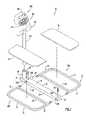
- FIG. 1is an exploded view in perspective of an exercise device according to the present invention.
- FIG. 2Ais side view in elevation of the base of the exercise device of FIG. 1 .
- FIG. 2Bis an exploded view in perspective of the interconnection of support platforms with a base of the exercise device of FIG. 1 .
- FIG. 2Cis a side view in cross-section of the effector bar of the exercise device of FIG. 1 .
- FIG. 3is a schematic block diagram of an exemplary control circuit for the exercise device of FIG. 1 .
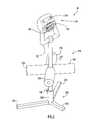
- FIG. 4is a view in perspective of the exercise device of FIG. 1 coupled to a video game system.
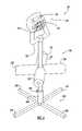
- FIG. 5is a view in perspective of an alternative embodiment of the exercise device of FIG. 1 according to the present invention.
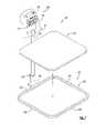
- FIG. 6is a view in perspective of the exercise device of FIG. 5 with an alternative base configuration according to the present invention.
- FIG. 7is a view in perspective of another embodiment of the exercise device of FIG. 1 according to the present invention.
- an exercise device 10is preferably coupled to a gaming system 400 .
- the gaming systemtypically includes a game processor 414 ( FIG. 3 ) and a monitor or display 416 .
- the game processorincludes a storage drive and/or unit to receive computer readable media (e.g., CD, DVD, etc.) containing software for various games and a processing device to execute the software to provide games on the monitor.
- the gaming systemmay be implemented by any conventional or other processing or gaming system (e.g., microprocessor system, personal computer, video gaming system, etc.).
- the gaming systemmay be implemented by conventional video games, such as PS2 available from Sony, XBOX available from Microsoft or GAMECUBE available from Nintendo.
- the gamesgenerally include characters or objects that are controlled by a user via a controller.
- the usermay control movement and actions of a character or a vehicle (e.g., car, airplane, boat, etc.) to move through a virtual environment displayed on the monitor.
- the controllerincludes a plurality of input devices (e.g., joystick, buttons, etc.) to enable a user to interact with the game.
- the gaming systemreceives signals from the controller and updates the display to reflect the movements and/or actions of the character or object as indicated by user manipulation of the controller.
- Exercise device 10serves as a game controller and enables a user to perform isometric exercises to control the game scenario.
- the exercise deviceis typically configured to be compact, portable and lightweight, preferably including a weight less than seventeen pounds.
- device 10includes a base 20 , support platforms 30 a , 30 b , an effector bar 110 and a controller 120 .
- Base 20is in the form of a substantially rectangular bar with front and rear surfaces 21 , 23 , side surfaces 25 , 27 and top and bottom surfaces 19 , 29 .
- the baseincludes a substantially cylindrical receptacle 28 attached to the base top surface proximate base front surface 21 and extending upward therefrom.
- the receptacleincludes dimensions suitable to receive effector bar 110 therein.
- base 20includes a length or longitudinal dimension of approximately eighteen inches, a width or transverse dimension of approximately two inches and a height or depth of approximately one inch, while receptacle 28 includes a height of approximately four inches.
- the base and receptaclemay be of any shape or size and include any suitable dimensions.
- Base 20includes a series of channels 22 a , 22 b defined therein and respectively positioned toward a corresponding base front and rear surface. The channels extend transversely through the base between side surfaces 25 , 27 and enable the base to engage support platforms 30 a , 30 b as described below.
- openings 24 a , 24 bare respectively defined in the base top surface toward base front surface 21 and base rear surface 23 substantially coincident a corresponding channel 22 a , 22 b .
- Threaded recesses 17 a , 17 bare defined in a base lower portion (proximate bottom surface 29 ) below respective channels 22 a , 22 b and substantially coincident corresponding openings 24 a , 24 b .
- Openings 24 a , 24 b and recesses 17 a , 17 beach include dimensions sufficient to accommodate a corresponding threaded bolt 26 .
- the threads of the boltare configured to engage the threads of recesses 17 a , 17 b to removably secure support platforms 30 a , 30 b to the base as described below.
- support platform 30 aincludes a generally ‘U’-shaped frame member 32 and a frame bar 34 .
- Frame member 32includes a support bar 31 with arms 33 , 35 extending substantially in parallel from respective ends of the support bar to form the generally ‘U’-shape.
- Frame bar 34is attached to the distal portions of arms 33 , 35 and extends between those arms across the open portion of generally ‘U’-shaped frame member 32 .
- the arms and frame bardefine an area within support platform 30 a to receive a plate 36 therein.
- the plateincludes a shape and dimensions sufficient to occupy and fit within that area.
- the plateis preferably constructed of a plastic material (e.g., ABS, PVC, etc.), but may be constructed of any suitable materials (e.g., wood, metal, plastic, fiberglass, etc.).
- support platform 30 aincludes a length or longitudinal dimension of approximately fourteen inches, a width or transverse dimension of approximately seven and one-half inches and a depth or thickness of approximately 0.5 inches
- plate 36includes a length or longitudinal dimension of approximately fourteen inches, a width or transverse dimension of approximately six and one-half inches and a depth or thickness of approximately 0.25 inches.
- the support platform and platemay be of any shape or size and include any suitable dimensions.
- Arm 33includes a shoulder or step 15 distally of frame bar 34 , where the arm upper portion is tapered distally of the shoulder to form a projection 37 .
- a threaded opening 39is defined through projection 37 to receive and engage bolt 26 as described below.
- arm 35includes a step or shoulder 16 distally of frame bar 34 , where the arm lower portion is tapered distally of the shoulder to form a projection 38 .
- This projectionincludes an opening 41 defined therethrough to receive bolt 26 as described below.
- projections 37 , 38include a length or longitudinal dimension of approximately one inch and a width or transverse dimension of approximately one inch. However, the projections may be of any shape or size and include any suitable dimensions.
- Support platform 30 bis substantially similar to support platform 30 a described above.
- Support platform 30 ais disposed proximate base side surface 25
- support platform 30 bis disposed proximate base side surface 27
- the support platformsare oriented in an inverted fashion with respect to each other.
- Projection 37 of support platform 30 bis inserted within channel 22 a of the base from side surface 27 with projection 38 of support platform 30 a being inserted within that channel from side surface 25 .
- Projection 37 of support platform 30 bis disposed within channel 22 a below projection 38 of support platform 30 a , where openings 39 , 41 of the projections, opening 24 a of the base and recess 17 a are aligned with each other to form a passage to receive bolt 26 .
- the boltis disposed through the passage with the bolt threads engaging the threads of projection opening 39 and recess 17 a to secure the support platforms to the front portion of the base.
- projection 37 of support platform 30 ais inserted within channel 22 b of the base from side surface 25 with projection 38 of support platform 30 b being inserted within that channel from side surface 27 .
- Projection 37 of support platform 30 ais disposed within channel 22 b below projection 38 of support platform 30 b , where openings 39 , 41 of the projections, opening 24 b of the base and recess 17 b are aligned with each other to form a passage to receive bolt 26 .
- the boltis disposed through the passage with the bolt threads engaging the threads of projection opening 39 and recess 17 b to secure support platforms 30 a , 30 b to the rear portion of the base.
- the support platformsmay be removed from the base by withdrawing bolts 26 from openings 24 a , 24 b and removing the respective projections 37 , 38 of support platforms 30 a , 30 b from base channels 22 a , 22 b.
- effector bar 110is received within receptacle 28 in a substantially upright position.
- the effector baris constructed of a suitably rigid material (e.g., a metal alloy) that is capable of being slightly deflected within its elastic limit in response to any combination of bending, twisting, tension and compression forces applied by the user to the bar. While the effector bar is generally cylindrical, it is noted that the effector bar may be of any suitable shape (e.g., bent or curved, V-shaped, etc.) and have any suitable exterior surface geometries (e.g., curved, multifaceted, etc.).
- a lock mechanism(not shown) may be employed to adjust the position of the effector bar within receptacle 28 in accordance with user characteristics (e.g., height, reach, etc.).
- a controller 120is attached or secured to the effector bar upper portion.
- the controlleris of the type available for conventional video games (e.g., PS2 available from Sony, XBOX available from Microsoft, GAMECUBE available from Nintendo, video gaming applications configured for use with personal computer operating systems such as Microsoft WINDOWS and Apple Mac OS X, etc.), such as the device described in U.S. Pat. No. 6,231,444, and is similar to the controllers disclosed in the aforementioned patent applications.
- the controllertypically includes a series of buttons 123 and a joystick 121 disposed on the controller upper portion.
- the joystick and effector barmay be selectively configured or assigned to game functions as described below.
- effector bar 110serves the function of a second controller joystick with respect to a game.
- the controllergenerally includes respective signal sources (e.g., variable resistor or potentiometers) to provide signals indicating joystick motion along X (e.g., left/right motions) and Y (e.g., forward/back motions) axes.
- signal sourcese.g., variable resistor or potentiometers
- joystick 121FIG. 3
- signal sources 125e.g., variable resistor or potentiometers
- the controllermay include any quantity of any type of input devices (e.g., buttons, switches, a keypad, joystick, etc.) and signal sources disposed at any location and arranged in any fashion on the controller.
- buttons and joystickmay be utilized to enter any desired information (e.g., enter desired user actions for the game, etc.).
- the controllermay include input devices 156 ( FIG. 3 ) to enter and reset resistance controls and reset clock or other functions, and input devices 157 to control function assignment of controller input devices as described below.
- Devices 156 , 157may be implemented by any conventional or other input devices (e.g., buttons, slides, switches, etc.).
- the controller lower portionincludes a generally “U”-shaped handle or grip 122 for engagement by a user.
- Effector bar 110includes at least one sensor to measure at least one type of strain applied by the user to that bar.
- effector bar 110includes strain gauge sensors 150 , 160 ( FIG. 3 ) that are arranged at suitable locations on the bar, preferably on the effector bar lower portion near receptacle 28 . These sensors measure the amount of a strain deformation applied to the bar as a result of the user applying pushing, pulling or lateral forces to the controller handle.
- sensor 150may measure force applied to the effector bar along an X-axis (e.g., lateral or left/right forces), while sensor 160 may measure forces applied to the effector bar along a Y-axis (e.g., push/pull or forward/backward forces).
- the sensorsmay be arranged with respect to the effector bar in any suitable manner to measure forces, such as the manners disclosed in the aforementioned patent applications.
- the sensorsmay be attached directly or indirectly to an effector bar exterior or interior surface to measure the applied forces.
- sensors 150 , 160are secured to a gauge mounting structure disposed within the effector bar in a manner similar to that disclosed in aforementioned U.S. patent application Ser. No. 11/133,449.
- a gauge mounting structure 108is secured within the hollow interior and extends substantially the length of effector bar 110 .
- the effector barpreferably includes at least one open end to facilitate insertion of the gauge mounting structure within the effector bar during assembly.
- the mounting structureis preferably an elongated hollow tube and has a transverse cross-sectional dimension (e.g., the outer diameter of the internal mounting structure) less than the transverse cross-sectional dimension of the effector bar (e.g., the internal diameter of the effector bar).
- a transverse cross-sectional dimensione.g., the outer diameter of the internal mounting structure
- the transverse cross-sectional dimension of the effector bare.g., the internal diameter of the effector bar.
- the gauge mounting structureis preferably constructed of a suitable material capable of being slightly deformed within its elastic limit in response to any combination of bending, twisting, tension and compression forces applied to the effector bar and translated to the gauge mounting structure as described below.
- This materialis generally more compliant and provides greater flexibility for the mounting structure in comparison to the effector bar.
- the gauge mounting structureis more flexible and is capable of deforming to a slightly greater extent or degree (e.g., has a greater deformation) than the effector bar without exceeding the elastic limit of the gauge mounting structure.
- the gauge mounting structureis preferably constructed of polyvinyl chloride (PVC) or any other suitable plastic or polymer material that is more compliant or flexible than the metal materials used to construct the effector bar.
- PVCpolyvinyl chloride
- the gauge mounting structureis stabilized within and indirectly secured along internal peripheral surface portions of the effector bar via suitable strain transfer materials preferably disposed proximate the longitudinal ends of the gauge mounting structure.
- the strain transfer materialsfacilitate transfer of forces or strains that are applied to the effector bar to the gauge mounting structure as described below.
- a fitting 112e.g., a PVC coupling
- a fitting 112is secured at a first end of gauge mounting structure 108 that corresponds with the first end of effector bar 110 (e.g., the effector bar end that is secured within receptacle 28 ).
- fitting 112may be secured at the second end of the gauge mounting structure that corresponds with the second, free end of the effector bar (e.g., the effector bar end toward controller 120 ).
- the fittingforms a sheath around the longitudinal outer periphery of the gauge mounting structure, and has a transverse cross-sectional dimension that is slightly less than the transverse cross-sectional dimension (e.g., inner diameter) of the effector bar.
- the outer surface portions of the fittingfrictionally engage the inner surface portions of the effector bar to provide a first indirect contact area or contact bridge between the effector bar and the gauge mounting structure at their corresponding first ends.
- This contact bridgeserves as one strain transfer location in which forces or strains applied to the effector bar are transferred to the gauge mounting structure.
- a first plug 114 of hardened epoxy resinis secured within annular gap 111 at a location adjacent fitting 112 .
- the first resin plugis secured to inner and outer peripheral surface portions of the effector bar and gauge mounting structure and to the adjacent end surface of the fitting to provide additional surface contact areas between the effector bar and the gauge mounting structure for facilitating strain transfer from the effector bar to the gauge mounting structure.
- a second plug 116 of hardened epoxy resinis disposed within annular gap 111 at the corresponding second ends of effector bar 110 and gauge mounting structure 108 .
- the second plugis secured to respective inner and outer peripheral surface portions of the effector bar and the gauge mounting structure to provide a second indirect contact area or contact bridge between the effector bar and the gauge mounting structure. This provides another location at which forces or strains applied to the effector bar are transferred to the gauge mounting structure.
- Second plug 116substantially fills the annular gap from a selected location along the gauge mounting structure to the structure second end.
- a foam collar 115is disposed in the annular gap and surrounds an outer peripheral surface portion of the gauge mounting structure at the selected location adjacent the second plug. The foam collar is provided to facilitate formation of the second plug of hardened epoxy resin during assembly of the effector bar.
- strain transfer materials described aboveinclude a fitting and hardened epoxy resin
- any suitable connecting or bridging materialmay be provided within the annular gap formed between the effector bar and the gauge mounting structure that facilitates transfer of applied forces from the effector bar to the gauge mounting structure.
- fittings and/or plugs of hardened epoxy resincan be secured at both opposing (e.g., first and second) ends of and/or at any other locations along the gauge mounting structure, where the fittings and/or plugs are suitably dimensioned to provide a contact or connecting bridge between corresponding inner and outer peripheral surface portions of the effector bar and the gauge mounting structure.
- strain transfer materialsare preferably suitably rigid to effect substantially complete transfer of forces between the effector bar and the gauge mounting structure with minimal or no absorbance of such forces by the strain transfer materials. While the preferred placement of strain transfer materials is at or near the opposing longitudinal ends of the effector bar and gauge mounting structure, the strain transfer materials may be disposed at any one or more suitable locations along the length of the effector bar depending upon a particular application.
- Sensors 150 , 160are affixed at suitable locations on outer surface portions of gauge mounting structure 108 between the locations of the strain transfer materials. Preferably, the sensors are disposed at suitable locations along the gauge mounting structure where, depending upon a particular design and/or application, deformation of the effector bar and/or the gauge mounting structure will likely be the greatest or most significant. In the embodiment of FIG. 2C , sensors 150 , 160 are secured on gauge mounting structure 108 at a location that is closer to the first (e.g., fixed) end (e.g., toward receptacle 28 ) of the gauge mounting structure in comparison to the second (e.g., free) end (e.g., toward controller 120 ) of the gauge mounting structure.
- the sensorsare further aligned in a longitudinal direction of both the effector bar and the gauge mounting structure and are angularly offset from each other by approximately ninety degrees on the outer periphery of the gauge mounting structure.
- the sensorsare aligned to measure bending deflections of gauge mounting structure 108 (e.g., corresponding with bending deflections of effector bar 110 that have been translated to the gauge mounting structure via the strain transfer materials) along at least two separate axes.
- the two separate axesmay be a predefined X axis and a predefined Y axis, where both axes are oriented in the same plane and angularly offset from each other by approximately ninety degrees.
- any suitable number of sensorsmay be provided and suitably aligned on the gauge mounting structure to measure compression, elongation, and twisting of the gauge mounting structure based upon similar forces acting upon and transferred from the effector bar.
- a third sensormay be affixed in a suitable alignment along the gauge mounting structure surface to measure twisting or torque deflections of the effector bar with respect to the longitudinal dimension of the effector bar. These deflections are translated from the effector bar to the gauge mounting structure (via the strain transfer materials described above) for measurement by the sensors.
- the sensorsare connected to a control circuit 200 ( FIG. 3 ) within controller 120 via appropriate wiring 126 , 128 , where the controller provides appropriate information to gaming system 400 ( FIG. 4 ).
- the information received by the gaming systemis processed to display a video game scenario on the gaming system.
- the scenariois updated in accordance with strain forces applied to the effector bar by a user.
- the controllermay further be configured to control the level of exertion required by a user in order to achieve a particular response in the video game scenario.
- Resistance levelsmay be input to an exercise processor 154 ( FIG. 3 ) by the user via input devices 156 (e.g., a keypad). Alternatively, or in combination with user input, the resistance levels may be controlled by the exercise processor based upon conditions within the video game scenario, such as changing wind conditions, changing grade of the terrain (e.g., going uphill), etc.
- a display 124( FIG. 1 ) is further disposed on the controller upper portion and may display various information to the user (e.g., the degree of force applied to a particular effector bar at any given time, the amount of work performed by the user during a particular exercise session, resistance levels, time or elapsed time, force applied to the various axes (X and Y axes), instantaneous force applied, total weight lifted, calories burned (e.g., based on the amount of work performed and user weight), resistance level setting, degree of effector bar movement and/or any other exercise or other related information).
- the displayis preferably implemented by a Liquid Crystal Display (LCD), but may be any type of display (e.g., LED, etc.).
- control circuitry 200includes sensors 150 , 160 and corresponding amplifiers 152 , 162 , exercise processor 154 , a switching device or matrix 158 and a signal processor 164 .
- a conventional power supply(not shown) provides appropriate power signals to each of the circuit components.
- the circuitmay be powered by a battery and/or any other suitable power source (e.g., the gaming system).
- a power switch(not shown) may further be included to activate the circuit components.
- the circuitmay include trim potentiometers 153 to adjust the centering and range of strain gauge sensors 150 , 160 .
- Sensors 150 , 160are each connected to a respective amplifier 152 , 162 .
- the electrical resistance of sensors 150 , 160vary in response to compression and stretching of the effector bar.
- Amplifiers 152 , 162basically amplify the sensor signals (e.g., in a range compatible with the type of controller employed).
- the amplified voltage valueis sent by each amplifier to exercise processor 154 and switching device 158 .
- Exercise processor 154may be implemented by any conventional or other processor and typically includes circuitry and/or converts the analog signals from the amplifiers to digital values for processing. Basically, the amplified sensor value represents the force applied by the user, where values toward the range maximum indicate greater applied force.
- the amplified analog valueis digitized or quantized within a range in accordance with the quantity of bits within the converted digital value (e.g., ⁇ 127 to +127 for eight bits signed, ⁇ 32,767 to +32,767 for sixteen bits signed, etc.) to indicate the magnitude and/or direction of the applied force.
- amplified voltage values toward the range maximumproduce digital values toward the maximum values of the quantization ranges.
- the exercise processorreceives resistance level and reset controls from the user via input devices 156 as described above, and controls amplifier gain parameters to adjust system resistance in accordance with the user specified controls.
- the exercise processoradjusts the gain control of the amplifiers in order to facilitate a resistance level in accordance with user input and/or the video game scenario.
- the gain control parameterbasically controls the amount of gain applied by the amplifier to an amplifier input (or sensor measurement). Since greater amplified values correspond to a greater force, increasing the amplifier gain enables a user to exert less force to achieve a particular amplified force value, thereby effectively lowering the resistance of the system for the user. Conversely, reducing the amplifier gain requires a user to exert greater force to achieve the particular amplified force value, thereby increasing the resistance of the system for the user.
- the exercise processorfurther adjusts an amplifier Auto Null parameter to zero or tare the strain gauge sensors.
- the exercise processoris further connected to display 124 to facilitate display of certain exercise or other related information as described above.
- the exercise processorreceives the amplified sensor values and determines various information for display to a user (e.g., the degree of force applied to a particular effector bar at any given time, the amount of work performed by the user during a particular exercise session, resistance levels, time or elapsed time, force applied to the various axes (X and Y axes), instantaneous force applied, total weight lifted, calories burned (e.g., based on the amount of work performed and user weight), resistance level setting, degree of effector bar movement and/or any other exercise or other related information).
- the exercise processorresets various parameters (e.g., resistance, time, work, etc.) in accordance with reset controls received from input devices 156 (e.g., to provide a new session for logging information).
- Switching device 158receives the signals from amplifiers 152 , 162 and is coupled to input devices or switch controls 157 , joystick 121 and signal processor 164 . Switching device 158 enables a user to selectively configure controller 120 for game functions as described below.
- effector bar 110FIG. 1
- joystick 121serves as the left controller joystick, where the functions of the joysticks with respect to a game may be selectively assigned by a user as described below.
- the effector barmay serve as any joystick or other input device.
- the switching devicereceives information from amplifiers 152 , 162 and is coupled to the inputs of signal processor 164 .
- the switching devicebasically enables information for controller input devices to be selectively placed on the signal processor inputs corresponding to the desired game functions.
- switching device 158is utilized to selectively exchange game functions between joystick 121 and the effector bar.
- the switching deviceincludes double pole double throw switches 166 , 168 that are respectively associated with X and Y motion axes.
- switch 166is associated with an X motion axis (e.g., lateral or right/left forces applied to the effector bar or joystick), while switch 168 is associated with the Y motion axis (e.g., forward/backward forces applied to the effector bar or joystick).
- a series of switching device outputs 170 , 172 and 174 , 176are respectively associated with switches 166 , 168 and are each coupled to specific inputs of signal processor 164 .
- the signal processor inputsare typically mapped to game functions in accordance with the game software executed by game processor 414 .
- Switches 166 , 168basically couple the signals from the desired devices (e.g., effector bar or joystick) to the signal processor inputs corresponding to the desired game functions in accordance with controls from a user entered via input devices or switch controls 157 .
- switch 166includes for each corresponding throw switch 180 , 182 switch contacts that are coupled to sensor 150 and to a signal source 125 of joystick 121 measuring X axis motion.
- Throw switch 180is associated with output 170
- throw switch 182is associated with output 172 .
- These outputseffectively represent the X axis (e.g., lateral or left/right) motion of controller joysticks.
- the throw switchesare configured in a manner to enable the signal from sensor 150 to be placed on one output and the joystick signal to be placed on the other output in accordance with the user control signals, thereby enabling the user to map the joystick or effector bar to a desired game function.
- switch 168includes for each corresponding throw switch 184 , 186 switch contacts that are coupled to sensor 160 and to a signal source 125 of joystick 121 measuring Y axis motion.
- Throw switch 184is associated with output 174
- throw switch 186is associated with output 176 .
- These outputseffectively represent the Y axis (e.g., forward/backward) motion of controller joysticks.
- the throw switchesare configured in a manner to enable the signal from sensor 160 to be placed on one output and the joystick signal to be placed on the other output in accordance with the user control signals, thereby enabling the user to map the joystick or effector bar to a desired game function.
- the functions of joysticks within a gamemay be selectively assigned to be performed by joystick 121 and/or the effector bar.
- the joystick or effector barmay individually perform the functions of two joysticks in accordance with the connections.
- the exercise devicemay include various devices (e.g., foot pedals, stairs, ski type exercisers, treadmills, cycling, etc.) that provide isokinetic and/or isotonic exercise features in addition to the isometric exercise features provided by the effector bar as described above. These exercise devices may similarly be assigned to game functions by the user in substantially the same manner described above.
- the signal sources associated with these devicesare coupled to switching device 158 to direct the signals associated with the exercise devices to the appropriate inputs of signal processor 164 .
- Switching device 158may alternatively be implemented by any quantity of any conventional or other devices capable of switching signals (e.g., switches, multiplexers, cross-bar switch, analog switches, digital switches, routers, logic, gate arrays, logic arrays, etc.) to accomplish the function assignments for the exercise device.
- switchese.g., switches, multiplexers, cross-bar switch, analog switches, digital switches, routers, logic, gate arrays, logic arrays, etc.
- the signals from the switching device outputsare transmitted to a respective predetermined memory location within signal processor 164 .
- the signal processormay be implemented by any conventional or other processor and typically includes circuitry and/or converts the analog signals from the switching device to digital values for processing in substantially the same manner described above.
- the signal processorsamples the memory locations at predetermined time intervals (e.g., preferably on the order of ten milliseconds or less) to continuously process and send information to the game processor to update and/or respond to an executing gaming application.
- the signal processorprocesses and arranges the switching device signals into suitable data packets for transmission to game processor 414 of gaming system 400 .
- the signal processormay process raw digital values in any fashion to account for various calibrations or to properly adjust the values within quantization ranges.
- the data packetsare in a format resembling data input from a standard peripheral device (e.g., game controller, etc.).
- the processormay construct a data packet that includes the status of all controller input devices (e.g., joystick 121 , buttons 123 , etc.) and the values of each sensor.
- the data packetmay include header information, X-axis information indicating a corresponding sensor force and joystick measurement along this axis, Y-axis information indicating a corresponding sensor force and joystick measurement along this axis, rudder or steering information, throttle or rate information and additional information relating to the status of input devices (e.g., buttons, etc.).
- Additional packet locationsmay be associated with data received from controller or other input and/or exercise devices coupled to the signal processor, where the input devices may represent additional operational criteria for the scenario (e.g., the firing of a weapon in the scenario when the user presses an input button, throttle, etc.).
- the game processorprocesses the information or data packets in substantially the same manner as that for information received from a conventional peripheral (e.g., game controller, etc.) to update and/or respond to an executing gaming application (e.g., game, etc.) displayed on monitor or display 416 of the gaming system.
- a conventional peripherale.g., game controller, etc.
- an executing gaming applicatione.g., game, etc.
- Exercise device 10may serve as a game controller that is operable with a wide variety of video gaming or other systems including PS2, XBOX and GAMECUBE systems, and various personal or other computers (e.g., personal computers with Microsoft WINDOWS and Apple Mac OS X operating systems).
- Exercise device 10includes a cable system that facilitates connection and communication between controller 120 and multiple (e.g., two or more) video gaming systems.
- a cable system 220is connected to and extends from a rear surface of controller 120 (e.g., a controller surface that opposes the controller surface including joystick 121 , buttons 123 and display 124 ) and at a location above controller handle 122 .
- Cable system 220is substantially similar to the cable system described in aforementioned U.S. patent application Ser. No. 11/097,370 and includes a flexible and hollow body 224 that extends into controller 120 via an access panel or door (not shown) to receive and retain wiring that is connected with signal processor 164 ( FIG. 3 ) within the controller.
- the cablemay connect with the controller at any other suitable location and/or in any other suitable manner.
- a number of separately and independently extending wiresare sheathed within and extend the length of cable body 224 . The wires are configured for providing an electrical contact or link between signal processor 164 of controller 120 and a specific video gaming system as described below.
- Cable body 224extends a selected distance from controller 120 and connects with a generally rectangular housing 226 .
- a number of flexible and hollow cables 227 , 230 , 240 , 250extend from housing 226 .
- the wiring within cable body 224extends within housing 226 for transfer of signals to wiring sets directed into and through a respective one of the output cables 227 , 230 , 240 , 250 .
- housing 226serves as a junction location for the transfer of signals between wiring within cable body 224 and respective wiring sets of the output cables, where each output cable includes a wiring set that is configured for connection to a game controller port of a corresponding video gaming system.
- connection plugsare each configured to connect with a corresponding game controller port of a respective video gaming system.
- the connection plugsconnect with the game controller ports in a male-female mating relationship.
- each connection plugincludes a male component with associated metal pins and/or other contacting structure that is configured for insertion into a corresponding female component of a respective controller port.
- connection plug 251is configured to connect with a game controller port of a GAMECUBE system
- connection plug 241is configured to connect with a game controller port of an XBOX system
- connection plug 231is configured to connect with a game controller port of a PS2 system
- connection plug 228is configured to connect with a universal serial bus (USB) port of any suitable gaming system or personal or other computer (e.g., to facilitate control of Microsoft WINDOWS or Apple Mac OS X based gaming or other applications).
- USBuniversal serial bus
- the cable systemis not limited to this exemplary configuration, but rather can include any suitable number (e.g., two or more) of connection plugs of any suitable types and configurations to facilitate connections with any types of video gaming or other systems.
- Cable system 220is of a suitable length (e.g., eight feet or greater) to facilitate a relatively easy connection between exercise device 10 and video gaming system 400 .
- the exercise devicemay employ an extension cable device 300 .
- Cable device 300is substantially similar to the cable device disclosed in aforementioned U.S. patent application Ser. No. 11/097,370, and is coupled to cable system 220 to connect the cable system with the video gaming system.
- extension cable device 300includes a flexible and hollow cable 302 that extends a suitable length (e.g., about 8 feet or greater) and includes a first housing 316 at a first end of the cable and a second housing 328 at a second end of the cable.
- Cable 302is substantially similar in configuration and design as cable 224 of cable system 220 , where the same or substantially similar wiring extends through the cable.
- cable 302can include one or more wires that transfer common or shared signals for two or more wiring sets.
- Each housing 316 , 328is substantially similar in configuration and design as housing 226 of cable system 220 .
- Each housingserves as a junction location to transfer signals between the wiring within cable 302 and each of a plurality of wiring sets in a similar manner as described above for housing 226 .
- a number of flexible and hollow cables 304 , 306 , 308 , 310extend from housing 316 .
- the housingis disposed between cable 302 and these cables to facilitate a connection.
- Each cable 304 , 306 , 308 , 310couples a respective wiring set therein to housing 316 and terminates at a respective connection plug 305 , 307 , 309 , 311 .
- the housingtransfers signals between the wiring sets and the appropriate wiring in cable 302 , where one or more of the wires of cable 302 may convey signals common to the gaming systems to reduce the quantity of wires employed by the cable.
- Connection plugs 305 , 307 , 309 , 311are complimentary with and configured for connection to corresponding connection plugs 227 , 231 , 241 , 251 of cable system 220 .
- the wiring sets disposed within the connection plugs of extension cable device 300include the same or substantially similar wiring as the wiring sets disposed within the corresponding connection plugs of cable system 220 .
- the connection plugs of the cable system and extension deviceconnect with each other in a male-female mating relationship, where a male component of each connection plug of cable system 220 is inserted into a female component of a corresponding connection plug of extension cable device 300 .
- a number of flexible and hollow cables 320 , 322 , 324 , 326extend from housing 328 .
- the housingis disposed between cable 302 and these cables to facilitate a connection.
- Each cable 320 , 322 , 324 , 326couples a respective wiring set therein to housing 328 and terminates at a respective connection plug 321 , 323 , 325 , 327 .
- the housingtransfers signals between the wiring sets and the appropriate wiring in cable 302 , where one or more of the wires of cable 302 may convey signals common to the gaming systems to reduce the quantity of wires employed by cable 302 as described above.
- Connection plugs 321 , 323 , 325 , 327are identical in configuration and design as corresponding connection plugs 227 , 231 , 241 , 251 of cable system 220 .
- each connection plug 321 , 323 , 325 , 327 of the extension cable deviceincludes a male component with associated metal pins and/or other metal contacting structure that is configured for insertion into a corresponding female component of a respective controller port to establish an electrical contact between the wiring set associated with the connection plug and corresponding wiring of the video gaming system to which the connection plug is connected.
- connection plug 321 , 323 , 325 , 327 of the extension cable deviceare further the same or substantially similar as the wiring sets of a corresponding connection plugs of cable system 220 .
- extension cable device 300can also be utilized with any video gaming system and corresponding game controller that include connecting components corresponding with any of the connection plug sets provided on the extension cable device. This enables the extension cable device to serve as a universal extension cable for a variety of different connection plug/port designs that exist for different video gaming systems and game controllers.
- Control circuitry 200 of the exercise device controlleris configured for effective communication and operability as a game controller with each of the video gaming systems associated with the wiring sets and cable connectors of the cable system.
- controller signal processor 164identifies the specific video gaming system with which control unit 120 is connected upon receiving one or more initial electrical signals (e.g., one or more “wake-up” signals) from the video gaming system.
- the controller signal processorprocesses and arranges signals into suitable data packets for transmission to and recognition by the video gaming system during a gaming application as described above.
- a usercouples the exercise device to video gaming system 400 utilizing the appropriate connection plug or plugs of cable system 220 and/or extension cable device 300 (e.g., the particular connection plug or plugs compatible with the gaming system).
- the usermay selectively assign game functions to the joystick, the effector bar and/or other input and/or exercise devices as described above.
- the usermay adjust the exercise device (e.g., controller height, etc.) to accommodate the user physical characteristics.
- the exercise deviceis placed on an appropriate surface (e.g., floor, chair, couch, bed, etc.), where the user is typically seated on exercise device 10 with user legs supported by support platforms 30 a , 30 b (e.g., with the legs extending over respective support platforms 30 a , 30 b ) and effector bar 110 disposed between the user legs.
- the user weight and/or bodybasically stabilizes the effector bar for manipulation. In other words, the user body or weight provides sufficient resistive or stabilizing forces for the effector bar to enable manipulation of that bar by the user.
- signal processor 164( FIG. 3 ) of controller 120 receives one or more initial signals from video gaming system 400 .
- the signal processoridentifies the specific video gaming system based on those initial signals and arranges data in suitable data packets for recognition by the identified system.
- a gameis selected and executed on the gaming system, and the user engages in an exercise to interact with the game.
- the useroperates the exercise device with the user legs supported by support platforms 30 a , 30 b and the user hands placed on controller handle 122 .
- the usergrips the controller handle and applies a force to the controller to exert a strain on the effector bar.
- the userapplies one or more forces to the controller and, hence, the effector bar with respect to at least one of the X and Y axes to produce a corresponding game movement (e.g., of a character or an object in the scenario displayed by the game processor).
- the usermay further manipulate joystick 121 , other controller input devices and/or other exercise devices for additional actions depending upon the particular game and user function assignments.
- the signals from strain gauge sensors 150 , 160 and controller input devicesare transmitted to the controller signal processor to generate data packets for transference to video gaming system 400 .
- the gaming systemprocesses the information or data packets in substantially the same manner as that for information received from a conventional peripheral (e.g., game controller, etc.) to update and/or respond to an executing gaming application.
- a conventional peripherale.g., game controller, etc.
- user exerciseserves to indicate desired user actions or movements to the gaming system to update movement or actions of characters or objects within the game in accordance with the function assigned to the bar.
- application of a forward force to the controllermay serve as the accelerator
- lateral force applied to the controllermay serve as the steering function.
- a single signal processoris implemented in the control circuit of the exercise device, where the signal processor is capable of communicating with a number of different video gaming systems in the manner described above.
- the present inventionis not limited to the use of a single processor.
- the exercise devicemay include multiple processors (e.g., two or more), where each processor is configured to enable communication of signals between the exercise device and at least one corresponding video gaming system as disclosed in the aforementioned patent applications.
- the electrical connection and/or communication between the one or more signal processors of the exercise deviceare not limited to the cable system and extension cable device described above. Rather, any suitable wired and/or wireless communication links can be provided that facilitate communication between one or more processors of the exercise device of the present invention and two or more different video gaming systems as disclosed in the aforementioned patent applications.
- exercise device 50includes a base 350 , effector bar 110 , a stability member 370 and controller 120 .
- Base 350includes a generally ‘Y’ type configuration with elongated branch members 352 , 354 and an elongated stem member 356 .
- the branch and stem memberstypically include a rectangular transverse cross section, where the branch members extend in opposing directions from the stem member distal end at an obtuse angle relative to the stem member, thereby forming the ‘Y’ type configuration.
- a substantially cylindrical receptacle 360is disposed at the junction of the stem and branch members. The receptacle extends upward from the base and includes dimensions sufficient to receive effector bar 110 for manipulation by a user as described below.
- Effector bar 110is substantially similar to the effector bar described above and is slidably received within receptacle 360 in a substantially upright position.
- a lock mechanism 158may be employed to adjust the position of the effector bar within receptacle 360 in accordance with user characteristics (e.g., height, reach, etc.) as described above.
- Controller 120is substantially similar to the controller described above and is attached or secured to the effector bar upper portion.
- the controllerpreferably includes buttons 123 , joystick 121 and display 124 disposed on the controller upper portion as described above.
- the joystick and effector barmay be selectively configured or assigned to game functions as described above.
- the controller lower portionincludes generally “U”-shaped handle or grip 122 for engagement by a user as described above.
- Stability member 370is disposed in sliding relation about effector bar 110 to enable a user to engage the stability member and stabilize the effector bar (e.g., enable a user to provide resistive or stabilizing forces for the effector bar) during user manipulation of that bar.
- the stability memberincludes a plurality of generally cylindrical support members 330 , 332 , 334 and 336 arranged in a cross type configuration (e.g., angularly displaced from each other by approximately ninety degrees) with an open central portion to receive effector bar 110 .
- the stability memberis in slidable relation with the effector bar and may be positioned along the effector bar at any desired location via any suitable conventional mechanisms (e.g., an O-ring, clamps, etc.).
- Support members 330 , 332are separated by a sufficient distance (e.g., angularly displaced by approximately ninety degrees) to enable a user leg or other body portion to be disposed between those members.
- support members 334 , 336are separated by a sufficient distance (e.g., angularly displaced by approximately ninety degrees) to enable a user leg or other body portion to be disposed between those members.
- user feetmay be placed on branch members 352 , 354 , where the user legs and feet engage the stability member and/or base to stabilize the effector bar (e.g., enable a user to provide resistive or stabilizing forces for the effector bar) for user manipulation of that bar.
- the support membersare preferably padded for user comfort.
- Effector bar 110typically includes at least one sensor to measure at least one type of strain applied by the user to that bar as described above.
- the sensorsmay be arranged as described above and measure the amount of a strain deformation applied to the bar as a result of the user applying pushing, pulling or lateral forces to the controller handle.
- the sensorsare connected to control circuit 200 ( FIG. 3 ) within controller 120 via appropriate wiring, where the controller provides appropriate information to gaming system 400 ( FIG. 4 ).
- Strain gauge measurementsare processed to display a video game scenario on the gaming system. The scenario is updated in accordance with strain forces applied to the effector bar by a user as described above.
- exercise device 50may include a base with a cross or plus type configuration as illustrated in FIG. 6 .
- exercise device 60is substantially similar to exercise device 50 ( FIG. 5 ) described above and includes a base 380 with a cross or plus type configuration.
- the baseincludes a plurality of generally rectangular base members 382 , 384 , 386 and 388 arranged in a cross type configuration (e.g., angularly displaced from each other by approximately ninety degrees) with an open central portion to receive receptacle 360 .
- the receptacleextends upward from the base and includes dimensions sufficient to receive effector bar 110 (with stability member 370 and controller 120 ) for manipulation by a user as described above.
- user feetmay be placed on base members 382 , 384 , 386 and/or 388 , where the user legs and feet engage the stability member and/or base to stabilize the effector bar (e.g., enable a user to provide resistive or stabilizing forces for the effector bar) for user manipulation of that bar.
- Base 380provides enhanced stability of exercise device 60 for manipulation of effector bar 110 .
- exercise devices 50 , 60Operation of exercise devices 50 , 60 is described with reference to FIGS. 4-6 . Initially, operation of these exercise devices is substantially similar to the manner of operation of exercise device 10 described above.
- a usercouples exercise device 50 , 60 to video gaming system 400 utilizing the appropriate connection plug or plugs of cable system 220 and/or extension cable device 300 (e.g., the particular connection plug or plugs compatible with the gaming system) in substantially the same manner described above for exercise device 10 .
- the usermay selectively assign game functions to the joystick, the effector bar and/or other input and/or exercise devices as described above.
- the usermay adjust the exercise device (e.g., controller height, stability member height, etc.) to accommodate the user physical characteristics.
- the useris typically seated (e.g., on the floor or couch, in a chair, etc.) with user legs engaging the support members (e.g., with the legs extending over respective support members 330 , 334 , and downward toward the base between support member pairs 330 , 332 and 334 , 336 ) and/or base as described above to stabilize the effector bar (e.g., enable a user to provide resistive or stabilizing forces for the effector bar).
- the usermay alternatively engage the stability member and/or base with any body portions in any suitable fashion to stabilize the effector bar.
- signal processor 164( FIG. 3 ) of controller 120 receives one or more initial signals from video gaming system 400 .
- the signal processoridentifies the specific video gaming system based on those initial signals and arranges data in suitable data packets for recognition by the identified system as described above.
- a gameis selected and executed on the gaming system, and the user engages in an exercise to interact with the game.
- the useroperates the exercise device with the user legs engaging the stability member and/or base and the user hands placed on controller handle 122 .
- the usergrips the controller handle and applies a force to the controller to exert a strain on the effector bar.
- the userapplies one or more forces to the controller and, hence, the effector bar with respect to at least one of the X and Y axes to produce a corresponding game movement (e.g., of a character or an object in the scenario displayed by the game processor).
- the usermay further manipulate joystick 121 , other controller input devices and/or other exercise devices for additional actions depending upon the particular game and user function assignments.
- the signals from the strain gauge sensors and input devicesare transmitted to the controller signal processor to generate data packets for transference to video gaming system 400 .
- the gaming systemprocesses the information or data packets in substantially the same manner as that for information received from a conventional peripheral (e.g., game controller, etc.) to update and/or respond to an executing gaming application as described above.
- FIG. 7Another alternative embodiment of exercise device 10 is illustrated in FIG. 7 .
- device 70includes a base platform 375 , effector bar 110 and controller 120 .
- Base platform 375includes a frame 372 and a plate 374 .
- Frame 372is substantially rectangular and includes front and rear bars 373 , 379 and side bars 377 , 378 that are collectively configured to form the frame rectangular configuration.
- a substantially cylindrical receptacle 376is attached to front bar 373 of frame 372 and extends upward therefrom.
- the receptacleincludes dimensions suitable to receive effector bar 110 therein.
- the frame barsdefine an area within base platform 375 to receive plate 374 therein.
- the plateincludes a shape and dimensions sufficient to occupy and fit within that area.
- the plateis preferably constructed of a plastic material (e.g., ABS, PVC, etc.), but may be constructed of any suitable materials (e.g., wood, metal, plastic, fiberglass, etc.).
- the base platform and platemay be of any shape or size and include any suitable dimensions.
- Effector bar 110is substantially similar to the effector bar described above and is slidably received within receptacle 376 in a substantially upright position.
- a lock mechanism 158may be employed to adjust the position of the effector bar within receptacle 376 in accordance with user characteristics (e.g., height, reach, etc.) as described above.
- Controller 120is substantially similar to the controller described above and is attached or secured to the effector bar upper portion.
- the controllerpreferably includes buttons 123 , joystick 121 and display 124 disposed on the controller upper portion as described above.
- the joystick and effector barmay be selectively configured or assigned to game functions as described above.
- the controller lower portionincludes generally “U”-shaped handle or grip 122 for engagement by a user as described above.
- Effector bar 110typically includes at least one sensor to measure at least one type of strain applied by the user to that bar as described above.
- the sensorsmay be arranged in the manner described above and measure the amount of a strain deformation applied to the bar as a result of the user applying pushing, pulling or lateral forces to the controller handle.
- the sensorsare connected to control circuit 200 ( FIG. 3 ) within controller 120 via appropriate wiring, where the controller provides appropriate information to gaming system 400 ( FIG. 4 ).
- Strain gauge measurementsare processed to display a video game scenario on the gaming system. The scenario is updated in accordance with strain forces applied to the effector bar by a user as described above.
- exercise device 70Operation of exercise device 70 is described with reference to FIGS. 4 and 7 .
- operation of exercise device 70is substantially similar to the manner of operation of the exercise devices described above.
- a usercouples exercise device 70 to video gaming system 400 utilizing the appropriate connection plug or plugs of cable system 220 and/or extension cable device 300 (e.g., the particular connection plug or plugs compatible with the gaming system) in substantially the same manner described above for exercise devices 10 , 50 and 60 .
- the usermay selectively assign game functions to the joystick, the effector bar and/or other input and/or exercise devices as described above.
- the usermay adjust the exercise device (e.g., controller height, etc.) to accommodate the user physical characteristics.
- the exercise deviceis placed on an appropriate surface (e.g., floor, chair, couch, bed, etc.), where the user is typically seated on exercise device 70 with user legs supported by base platform 375 (e.g., with the legs extending over frame 372 and plate 374 ) and effector bar 110 disposed between the user legs.
- the user weight and/or bodybasically stabilizes the effector bar (e.g., enables a user to provide resistive or stabilizing forces for the effector bar).
- signal processor 164( FIG. 3 ) of controller 120 receives one or more initial signals from video gaming system 400 .
- the signal processoridentifies the specific video gaming system based on those initial signals and arranges data in suitable data packets for recognition by the identified system as described above.
- a gameis selected and executed on the gaming system, and the user engages in an exercise to interact with the game.
- the useroperates the exercise device with the user legs supported by base platform 375 and the user hands placed on controller handle 122 .
- the usergrips the controller handle and applies a force to the controller to exert a strain on the effector bar.
- the userapplies one or more forces to the controller and, hence, the effector bar with respect to at least one of the X and Y axes to produce a corresponding game movement (e.g., of a character or an object in the scenario displayed by the game processor).
- the usermay further manipulate joystick 121 , other controller input devices and/or other exercise devices for additional actions depending upon the particular game and user function assignments.
- the signals from the strain gauge sensors and input devicesare transmitted to the controller signal processor to generate data packets for transference to video gaming system 400 .
- the gaming systemprocesses the information or data packets in substantially the same manner as that for information received from a conventional peripheral (e.g., game controller, etc.) to update and/or respond to an executing gaming application as described above.
- Exercise device 10 and the corresponding componentsmay be of any size or shape, may be arranged in any fashion and may be constructed of any suitable materials.
- the basemay be of any size or shape, and include any quantity of channels of any size or shape defined in the base at any suitable locations and extending in any directions (e.g., transversely, longitudinally, at any desired angles, partially or entirely through the base, etc.).
- the openingsmay be of any quantity, size or shape and may be defined in the base at any suitable locations.
- the recessesmay be of any quantity, size or shape and may be defined in the base at any suitable locations.
- the recesses and openingsmay be threaded in any fashion or combination.
- the openings, recesses and channelsmay be configured in any conventional or other manner to engage the bolt or other securing mechanism to secure the support platforms to the base.
- the boltmay be of any quantity, size or shape and may be implemented by any securing mechanism (e.g., bolt, screw, pin, clamp, etc.).
- the receptaclemay be of any quantity, shape or size and may be disposed at any suitable location to receive the effector bar.
- the locking mechanismmay include any type of locking device (e.g., friction device, clamp, peg and hole arrangement, etc.) to releasably maintain an exercise device component in a desired position or orientation to accommodate a user.
- the support platformsmay be of any quantity, shape, size or suitable materials with the same or different configuration.
- the support platformsmay be permanently or removably secured to the base at any suitable locations, and may support any desired user body portions (e.g., legs, arms, torso, etc.), where the user may utilize the device in any suitable position (e.g., sitting down, standing, lying down, etc.).
- the frame membermay be of any shape or size and include any quantity of arms and/or bars (e.g., support, frame, etc.) of any shape or size and configured in any manner.
- the arms, frame bar and support barmay be of any quantity, shape or size and configured in any manner (e.g., extend in parallel, at any angle, etc.)).
- the projectionsmay be of any quantity, shape or size and include any configuration to enable mating with a corresponding support platform (e.g., tapered lower or upper sections, complementary configurations (e.g., hook and opening, clasp, etc.), etc.).
- the projection openingsmay be of any quantity, shape or size, may be defined at any suitable locations and may include any configuration to engage a securing mechanism (e.g., threads, etc.).
- the platemay be of any quantity, shape or size, may be constructed of any suitable materials and may be disposed within the support platform at any desired location or in any orientation.
- Exercise device 50 and the corresponding componentsmay be of any size or shape, may be arranged in any fashion and may be constructed of any suitable materials.
- the branch and stem membersmay be of any quantity, shape or size, may be constructed of any suitable materials and may be arranged in any fashion (e.g., ‘T’, ‘X’ or ‘Y’ configuration, cross or plus configuration, star configuration, any angular offset, etc.).
- the support membersmay be of any quantity, shape or size, may be constructed of any suitable materials and may be arranged in any fashion (e.g., ‘T’, ‘X’ or ‘Y’ configuration, cross or plus configuration, star configuration, any angular offset, etc.).
- the support membersmay include any desired foam or padding for user comfort.
- the stability membermay be adjustable relative to the effector bar via any conventional or other techniques (e.g., friction device, clamp, peg and hole arrangement, etc.) to accommodate user characteristics.
- the stability member and basemay accommodate any desired user body portions (e.g., legs, arms, torso, etc.), where the user may utilize the device in any suitable position (e.g., sitting down, standing, lying down, etc.).
- the receptaclemay be of any quantity, shape or size and may be disposed at any suitable location to receive the effector bar.
- the locking mechanismmay include any type of locking device (e.g., friction device, clamp, peg and hole arrangement, etc.) to releasably maintain an exercise device component in a desired position or orientation to accommodate a user.
- Exercise device 60 and the corresponding componentsmay be of any size or shape, may be arranged in any fashion and may be constructed of any suitable materials.
- the base membersmay be of any quantity, shape or size, may be constructed of any suitable materials and may be arranged in any fashion (e.g., ‘T’, ‘X’ or ‘Y’ configuration, cross or plus configuration, star configuration, any angular offset, etc.).
- the support membersmay be of any quantity, shape or size, may be constructed of any suitable materials and may be arranged in any fashion (e.g., ‘T’, ‘X’ or ‘Y’ configuration, cross or plus configuration, star configuration, any angular offset, etc.).
- the support membersmay include any desired foam or padding for user comfort.
- the stability membermay be adjustable relative to the effector bar via any conventional or other techniques (e.g., friction device, clamp, peg and hole arrangement, etc.) to accommodate user characteristics.
- the stability member and basemay accommodate any desired user body portions (e.g., legs, arms, torso, etc.), where the user may utilize the device in any suitable position (e.g., sitting down, standing, lying down, etc.).
- the receptaclemay be of any quantity, shape or size and may be disposed at any suitable location to receive the effector bar.
- the locking mechanismmay include any type of locking device (e.g., friction device, clamp, peg and hole arrangement, etc.) to releasably maintain an exercise device component in a desired position or orientation to accommodate a user.
- Exercise device 70 and the corresponding componentsmay be of any size or shape, may be arranged in any fashion and may be constructed of any suitable materials.
- the base platformmay support any desired user body portions (e.g., legs, arms, torso, etc.), where the user may utilize the device in any suitable position (e.g., sitting down, standing, lying down, etc.).
- the framemay be of any quantity, shape or size, and may be constructed of any suitable materials.
- the framemay include any quantity of bars of any shape, size or suitable materials, where the bars may be configured or arranged in any manner.
- the platemay be of any quantity, shape or size, may be constructed of any suitable materials and may be disposed within the frame at any desired location and in any orientation.
- the receptaclemay be of any quantity, shape or size and may be disposed at any suitable location to receive the effector bar.
- the locking mechanismmay include any type of locking device (e.g., friction device, clamp, peg and hole arrangement, etc.) to releasably maintain an exercise device component in a desired position or orientation to accommodate a user.
- the effector bar for the exercise devicesmay be constructed of any suitable materials that preferably are subject to measurable deflection within an elastic limit of the materials when subjected to one or more straining or other forces by the user.
- the effector barmay have any suitable geometric configurations, and two or more effector bars may be combined in any suitable manner to yield a device that conforms to a desired design for a user for a particular application.
- the effector barmay be positioned at any desired orientation or angle (e.g., the receptacle may be angled, the effector bar may be disposed within the receptacle at an angle, the effector bar may be adjustable to any desired angle by a user, etc.).
- the exercise devicesmay further include various exercise mechanisms to control the video game and provide further exercise for a user (e.g., cycling, stair mechanism, etc.).
- any suitable number of any types of sensorsmay be applied to an effector bar and/or gauge mounting structure to facilitate the measurement of any one or more types of strain or other forces applied by the user (e.g., bending forces, twisting forces, compression forces and/or tension forces).
- the exercise devicesmay be utilized on any suitable surface (e.g., floor, couch, bed, etc.) and may be adjustable in any fashion (e.g., any dimension, controller and/or stability member height, etc.) via any types of arrangements of components (e.g., telescoping arrangement, overlapping arrangement, extender components, etc.) to accommodate user physical characteristics.
- the sensorsmay be constructed of any suitable materials, may be disposed at any locations on the effector bar and/or gauge mounting structure and may be of any suitable type (e.g., strain gauge, etc.). Further, the sensors may include any electrical, mechanical or chemical properties that vary in a measurable manner in response to applied force to measure force applied to an object.
- the sensorsmay include any desired arrangement.
- the exercise devicesmay include any suitable number of effector bars and gauge mounting structures secured within the effector bars.
- the gauge mounting structuresmay be constructed of any suitable materials that preferably permit their deformation within an elastic limit as a result of bending, twisting, compression and/or torque forces applied to the effector bar.
- the gauge mounting structuresare constructed of materials that are more compliant and have greater flexibility than the effector bars to which they are secured when each are subjected to the same amount and/or type of forces.
- the gauge mounting structuresmay have any suitable geometric configurations that preferably facilitate securing of one or more gauge mounting structures within an effector bar, and two or more effector bars may be combined in any suitable manner to yield a system frame that conforms to a desired design for a user for a particular application.
- the gauge mounting structuresmay be hollow or solid.
- the strain gauge sensorsmay be secured at suitable locations to outer surface portions on the gauge mounting structure with associated wiring extending within the annular gap between the gauge mounting structure and the effector bar.
- the gauge mounting structuresmay be solid structures, where both the strain gauges and wiring are secured and/or extend from outer surface portions of the gauge mounting structures.
- Strain transfer materialsmay be provided of any suitable types, sizes and configurations to facilitate transfer of applied forces from the effector bars to one or more gauge mounting structures disposed within the effector bars.
- the strain transfer materialscan be formed of any suitable materials that effect a transfer of at least a portion of the applied forces from the effector bar to the gauge mounting structure.
- the strain transfer materialsmay be disposed at any one or more suitable locations within the effector bars to provide a connection at selected surface locations between the effector bars and the gauge mounting structures.
- gauge mounting structuresmay be designed to include one or more suitably sized and configured outer peripheral sections that frictionally engage with interior peripheral surface portions of the effector bars so as to facilitate one or more strain transfer contacting surfaces between the gauge mounting structures and the effector bars.
- the controller for the exercise devicesmay be of any shape or size, may be constructed of any suitable materials, and may be of the type of any commercially available or other game controller (e.g., those for use with PS2, XBOX, GAMECUBE, etc.).
- the controllermay include any quantity of any types of input devices (e.g., buttons, slides, joysticks, track type balls, etc.) disposed at any locations and arranged in any fashion.
- the controllermay include any quantity of any types of signal source devices to generate signals in accordance with input device manipulation (e.g., variable resistors or potentiometers, switches, contacts, relays, sensors, strain gauges, etc.).
- the signal sourcesmay correspond with any quantity of axes for an input device.
- controller input devicesmay be implemented as force sensing or isometric devices, while the controller input devices may be assigned to any suitable game functions.
- the controllermay include any quantity or combination of force sensing input devices and motion input devices.
- the controller handlemay be of any quantity, shape or size and may be disposed at any location to receive force applied by a user. Alternatively, the user may apply force directly to the effector bar.
- the effector bar and/or other input devicesmay be assigned the gaming functions of any desired controller input devices.
- the switching matrix or devicemay be implemented by any quantity of any conventional or other devices capable of switching signals (e.g., switches, multiplexers, cross-bar switch, analog switches, digital switches, routers, logic, gate arrays, logic arrays, processor, etc.).
- the switch controlsmay include a control processor to control the switching device in accordance with the controls to achieve the desired function assignment.
- the switch controlsmay be implemented by any conventional or other control or input devices (e.g., processor, slides, switches, buttons, etc.) to provide control signals to the switching device or control processor.
- the switching device or switch controlsmay alternatively provide a user interface to enable the user to enter information to configure the controller in the desired manner.
- the interfacemay be in the form of screens on a controller display or controller lights or other indicators. Further, the interface may be shown on the gaming system display and implemented by the game processor of the gaming system.
- the control processormay be implemented by any conventional or other processor or circuitry (e.g., microprocessor, controller, etc.).
- the switching devicemay direct signals from any quantity of inputs to any quantity of outputs in accordance with user-specified or other controls and may map any controller input devices and/or exercise mechanisms to any suitable game functions.
- the switching devicemay be disposed internal or external of the controllers.
- the gaming systemmay be implemented by any quantity of any personal or other type of computer or processing system (e.g., IBM-compatible, Apple, Macintosh, laptop, palm pilot, microprocessor, gaming consoles such as the XBOX system from Microsoft Corporation, the PLAY STATION 2 system from Sony Corporation, the GAMECUBE system from Nintendo of America, Inc., etc.).
- the gaming systemmay be a dedicated processor or a general purpose computer system (e.g., personal computer, etc.) with any commercially available operating system (e.g., Windows, OS/2, Unix, Linux, etc.) and/or commercially available and/or custom software (e.g., communications software, application software, etc.) and any types of input devices (e.g., keyboard, mouse, microphone, etc.).
- the gaming systemmay execute software from a recorded medium (e.g., hard disk, memory device, CD, DVD or other disks, etc.) or from a network or other connection (e.g., from the Internet or other network).
- the controllermay arrange data representing force measurements by sensors and other controller information into any suitable data packet format that is recognizable by the gaming system or host computer system receiving data packets from the controller.
- the data packetsmay be of any desired length, include any desired information and be arranged in any desired format.
- Any suitable number of any type of conventional or other displaysmay be connected to the controller or gaming system to provide any type of information relating to a particular computer session.
- a displaymay be located at any suitable location on or remote from the controller.
- Each of the exercise devicesmay be adjustable in any fashion (e.g., any dimension, controller and/or support height, controller and/or support orientation or distance to the user, etc.) via any types of arrangements of components (e.g., telescoping arrangement, overlapping arrangement, extender components, etc.) to accommodate user physical characteristics.
- the locking mechanismsmay include any type of locking device (e.g., friction device, clamp, peg and hole arrangement, etc.) to releasably maintain an exercise system component in a desired position or orientation to accommodate a user.
- the processorsmay be implemented by any quantity of any type of microprocessor, processing system or other circuitry, while the control circuitry may be disposed at any suitable locations on the devices, within the controller or, alternatively, remote from the devices.
- the control circuitry and/or signal processormay be connected to one or more game processors or host computer systems via any suitable peripheral, communications media or other port of those systems.
- the signal processorsmay further arrange digital data (e.g., force or other measurements by sensors, controller information, etc.) into any suitable data packet format that is recognizable by the game processor or host computer system receiving data packets from the signal processors.
- the data packetsmay be of any desired length, include any desired information and be arranged in any desired format.
- the signal processormay sample the information at any desired sampling rate (e.g., seconds, milliseconds, microseconds, etc.), or receive measurement values or other information in response to interrupts.
- the analog valuesmay be converted to a digital value having any desired quantity of bits or resolution.
- the processorse.g., control, signal, exercise, etc.
- the processorsmay process raw digital values in any desired fashion to produce information for transference to the display, game processor or host computer system. This information is typically dependent upon a particular application.
- the correlation between the measured force or exercise motion and provided value for that force or motionmay be determined in any desired fashion.
- the amplified measurement rangemay be divided into units corresponding to the resolution of the digital value.
- each incrementrepresents 1/256 of the voltage range. With respect to a five volt range, each increment is 5/256 of a volt, which is approximately 0.02 volts. Thus, for an amplified force measurement of three volts, the digital value may correspond to approximately 150 (e.g., 3.0/0.2).
- any suitable number of any types of conventional or other circuitrymay be utilized to implement the control circuit, amplifiers, sensors, trim potentiometers, switching device and processors (e.g., exercise, control, signal, etc.).
- the amplifiersmay produce an amplified value in any desired voltage range, while the A/D conversion may produce a digitized value having any desired resolution or quantity of bits (e.g., signed or unsigned).
- the control circuitmay include any quantity of the above or other components arranged in any fashion.
- the resistance change of the sensorsmay be determined in any manner via any suitable conventional or other circuitry.
- the amplifiers and processors(e.g., exercise, signal, etc.) may be separate within a circuit or integrated as a single unit.
- Any suitable number of any type of conventional or other displaysmay be connected to the processors (e.g., exercise, signal, control, game, etc.), where the processors may provide any type of information relating to a particular computer interactive exercise session (e.g., results from isometric exercises including force and work, results from motion exercise including speed and distance traveled, calories burned, weight lifted, etc.).
- a displaymay be located at any suitable location on or remote from the exercise devices.
- the control circuitry and/or signal processors of the game controllersmay be connected to one or more game processors of video gaming or host computer systems via any suitable peripheral, communications media or other port of those systems.
- Any suitable number and types of wired and/or wireless devicesmay be provided to facilitate communications between game controllers and video gaming systems.
- any suitable number of cablescan be provided and configured for connection with each other, with each cable including one or more suitable wiring sets with one or more wires, to facilitate connection with two or more video gaming systems.
- the cable junctions of the cable system and extension cable devicemay transfer signals between the wires within the cable and wiring sets in any fashion (e.g., direct connection of wires, connection to a terminal, etc.).
- the wiring of the cablemay be connected to any quantity of wiring sets, where the cable wiring may utilize one or more wires to transfer gaming signals common to any quantity of wiring set wires to reduce the quantity of wires employed in the cable.
- the cablemay include a dedicated wire for each wiring set wire.
- Any suitable number and types of housings or other structuresmay be connected with one or more cables to facilitate transfer of signals between wiring extending within a cable and wiring sets for transfer into separate cables.
- Any suitable number and types of connectorse.g., male and/or female connection plugs
- the cable system and extension cable devicemay include cables of any suitable lengths.
- the wake-up signalmay include any signal or desired information to identify a gaming system (e.g., voltage or current level, gaming system identifier, etc.).
- wireless communication linkse.g., transmitters, receivers and/or transceivers
- signalse.g., RF and/or IR
- One or more signal processorsmay be connected with one or more wireless communication links to facilitate communications between a game controller and one or more video gaming systems.
- one or more signal processorsmay be provided within a communication device (e.g., a transceiver), connection plugs and/or other connecting structure that connects with one or more video gaming systems, where the signal processors are configured to identify video gaming systems to which they are connected and convert data transmissions for recognition by a game controller and/or a video gaming system that are linked to each other.
- a communication devicee.g., a transceiver
- connection plugse.g., a transceiver
- other connecting structurethat connects with one or more video gaming systems
- a universal adaptormay be provided that is generic and configured to connect with any selected types of game controllers and video gaming systems, where the universal adaptor includes one or more suitable signal processors to identify a specific video gaming system and to effectively convert data transmissions for recognition by each of the game controller and the specific video gaming system that is connected to the game controller via the universal adaptor.
- the universal adaptormay include one or more cables to sheath one or more sets of wiring and/or one or more suitable wireless communication devices (e.g., transmitters, receivers and/or transceivers, etc.) to facilitate wireless communications.
- the input devicesmay be provided on any suitable number of control panels that are accessible by the user during system operation and have any suitable configuration (e.g., buttons, switches, keypads, etc.).
- the exercise mechanismse.g., foot pedals, stairs, ski type exercisers, treadmills, etc.
- the exercise mechanismsmay provide any isokinetic and/or isotonic exercise features in addition to or instead of the isometric exercise features provided by effector bars.
- the exercise mechanismsmay be assigned to any desired game functions in the manner described above and may further be resistance controlled by the exercise processor, where control signals may be transmitted to a resistance or braking device or the amount of effort required by the user may be modified.
- the resistance level for the effector bar and exercise mechanismsmay be controlled by adjusting amplifier or other parameters. Alternatively, the resistance level may be controlled based on thresholds entered by a user.
- the processorse.g., exercise and/or signal processors
- the processorsmay be configured to require a threshold resistance level be achieved, which is proportionate to the amount of straining force applied by the user to one or more effectors or to an amount of motion or force applied to an exercise mechanism (e.g., rate of stair climbing or pedaling, etc.) before assigning appropriate data values to the data packets to be sent to the game processor or host computer.
- Threshold values for the change in resistancemay be input to the processor by the user via an appropriate input device (e.g., a keypad).
- the software of the exercise devices and/or processorsmay be implemented in any desired computer language, and could be developed by one of ordinary skill in the computer and/or programming arts based on the functional description contained herein. Further, any references herein of software performing various functions generally refer to computer systems or processors performing those functions under software control.
- the processorse.g., control, exercise, signal, switching device, etc.
- the processorsmay alternatively be implemented by hardware or other processing circuitry, or may be implemented on the game processor or host system as software and/or hardware modules receiving the sensor and/or input device information or signals.
- processorse.g., control, exercise, signal, game, switching devices, etc.
- processorsmay be distributed in any manner among any quantity (e.g., one or more) of hardware and/or software modules or units, processors, computer or processing systems or circuitry, where the processors, computer or processing systems or circuitry may be disposed locally or remotely of each other and communicate via any suitable communications medium (e.g., LAN, WAN, Intranet, Internet, hardwire, modem connection, wireless, etc.).
- suitable communications mediume.g., LAN, WAN, Intranet, Internet, hardwire, modem connection, wireless, etc.
- the present invention exercise devicesare not limited to the gaming applications described above, but may be utilized as a peripheral for any processing system, software or application.
- the inventionmakes available a novel isometric exercise system and method of facilitating user exercise during video game play, wherein an isometric exercise device serves as a controller for video games or other applications to enable users to exercise during game play or computer simulations.
Landscapes
- Engineering & Computer Science (AREA)
- Multimedia (AREA)
- Health & Medical Sciences (AREA)
- Human Computer Interaction (AREA)
- General Health & Medical Sciences (AREA)
- Physical Education & Sports Medicine (AREA)
- Chemical & Material Sciences (AREA)
- Chemical Kinetics & Catalysis (AREA)
- Life Sciences & Earth Sciences (AREA)
- Biophysics (AREA)
- Orthopedic Medicine & Surgery (AREA)
- Theoretical Computer Science (AREA)
- Position Input By Displaying (AREA)
- User Interface Of Digital Computer (AREA)
Abstract
Description
Claims (34)
Priority Applications (9)
| Application Number | Priority Date | Filing Date | Title |
|---|---|---|---|
| US11/350,284US7699755B2 (en) | 2002-12-04 | 2006-02-09 | Isometric exercise system and method of facilitating user exercise during video game play |
| JP2008521511AJP2009501063A (en) | 2005-07-15 | 2006-07-12 | Isometric exercise system and method for facilitating user exercise while playing video games |
| PCT/US2006/026826WO2007011573A2 (en) | 2005-07-15 | 2006-07-12 | Isometric exercise system and method of facilitating user exercise during video game play |
| EP06786848AEP1907073A2 (en) | 2005-07-15 | 2006-07-12 | Isometric exercise system and method of facilitating user exercise during video game play |
| US11/562,449US20070155589A1 (en) | 2002-12-04 | 2006-11-22 | Method and Apparatus for Operatively Controlling a Virtual Reality Scenario with an Isometric Exercise System |
| EP06838450AEP1960063A2 (en) | 2005-11-28 | 2006-11-28 | Method and apparatus for operatively controlling a virtual reality scenario with an isometric exercise system |
| JP2008542472AJP2009520513A (en) | 2005-11-28 | 2006-11-28 | Method and apparatus for controlling virtual reality scenarios using isometric exercises |
| PCT/US2006/045489WO2007062238A2 (en) | 2005-11-28 | 2006-11-28 | Method and apparatus for operatively controlling a virtual reality scenario with an isometric exercise system |
| US11/851,460US20070298883A1 (en) | 2002-12-04 | 2007-09-07 | Method and Apparatus for Operatively Controlling a Virtual Reality Scenario in Accordance With Physical Activity of a User |
Applications Claiming Priority (6)
| Application Number | Priority Date | Filing Date | Title |
|---|---|---|---|
| US10/309,565US7121982B2 (en) | 2002-12-04 | 2002-12-04 | Computer interactive isometric exercise system and method for operatively interconnecting the exercise system to a computer system for use as a peripheral |
| US51489703P | 2003-10-29 | 2003-10-29 | |
| US10/806,280US20040180719A1 (en) | 2002-12-04 | 2004-03-23 | Game controller support structure and isometric exercise system and method of facilitating user exercise during game interaction |
| US10/975,185US20050130742A1 (en) | 2002-12-04 | 2004-10-28 | Configurable game controller and method of selectively assigning game functions to controller input devices |
| US69938405P | 2005-07-15 | 2005-07-15 | |
| US11/350,284US7699755B2 (en) | 2002-12-04 | 2006-02-09 | Isometric exercise system and method of facilitating user exercise during video game play |
Related Parent Applications (1)
| Application Number | Title | Priority Date | Filing Date |
|---|---|---|---|
| US10/975,185Continuation-In-PartUS20050130742A1 (en) | 2002-12-04 | 2004-10-28 | Configurable game controller and method of selectively assigning game functions to controller input devices |
Related Child Applications (1)
| Application Number | Title | Priority Date | Filing Date |
|---|---|---|---|
| US11/562,449Continuation-In-PartUS20070155589A1 (en) | 2002-12-04 | 2006-11-22 | Method and Apparatus for Operatively Controlling a Virtual Reality Scenario with an Isometric Exercise System |
Publications (2)
| Publication Number | Publication Date |
|---|---|
| US20060217243A1 US20060217243A1 (en) | 2006-09-28 |
| US7699755B2true US7699755B2 (en) | 2010-04-20 |
Family
ID=37669333
Family Applications (1)
| Application Number | Title | Priority Date | Filing Date |
|---|---|---|---|
| US11/350,284Expired - Fee RelatedUS7699755B2 (en) | 2002-12-04 | 2006-02-09 | Isometric exercise system and method of facilitating user exercise during video game play |
Country Status (3)
| Country | Link |
|---|---|
| US (1) | US7699755B2 (en) |
| EP (1) | EP1907073A2 (en) |
| WO (1) | WO2007011573A2 (en) |
Cited By (34)
| Publication number | Priority date | Publication date | Assignee | Title |
|---|---|---|---|---|
| US20060111181A1 (en)* | 2004-11-24 | 2006-05-25 | Thorsen Michael L | Steering wheel stand for electronic game control |
| US20080102424A1 (en)* | 2006-10-31 | 2008-05-01 | Newgent, Inc. | Instruction Delivery Methodology & Plurality of Smart, Kinetic-Interactive-Devices (K.I.D.s) |
| US20120028760A1 (en)* | 2007-04-13 | 2012-02-02 | Armin Armani | Portable isometric exercise device and method |
| US8287434B2 (en) | 2008-11-16 | 2012-10-16 | Vyacheslav Zavadsky | Method and apparatus for facilitating strength training |
| US20140113769A1 (en)* | 2012-10-18 | 2014-04-24 | Footwear & Recreation Technology Research Institute | Exercisers with smart manage system and methods using the same |
| US8734157B1 (en) | 2010-11-11 | 2014-05-27 | Julius Andrew Hummel, III | Exercise and gaming apparatus |
| US9229476B2 (en) | 2013-05-08 | 2016-01-05 | EZ as a Drink Productions, Inc. | Personal handheld electronic device with a touchscreen on a peripheral surface |
| US9230064B2 (en) | 2012-06-19 | 2016-01-05 | EZ as a Drink Productions, Inc. | Personal wellness device |
| US9262064B2 (en) | 2013-07-09 | 2016-02-16 | EZ as a Drink Productions, Inc. | Handheld computing platform with integrated pressure sensor and associated methods of use |
| US20170065880A1 (en)* | 2015-09-07 | 2017-03-09 | Blue Goji Corp. | Multiple electronic control devices |
| US20180214761A1 (en)* | 2017-01-27 | 2018-08-02 | The Johns Hopkins University | Rehabilitation and training gaming system to promote cognitive-motor engagement description |
| US10102345B2 (en) | 2012-06-19 | 2018-10-16 | Activbody, Inc. | Personal wellness management platform |
| US10124246B2 (en) | 2014-04-21 | 2018-11-13 | Activbody, Inc. | Pressure sensitive peripheral devices, and associated methods of use |
| US10133849B2 (en) | 2012-06-19 | 2018-11-20 | Activbody, Inc. | Merchandizing, socializing, and/or gaming via a personal wellness device and/or a personal wellness platform |
| US10188890B2 (en) | 2013-12-26 | 2019-01-29 | Icon Health & Fitness, Inc. | Magnetic resistance mechanism in a cable machine |
| US10220259B2 (en) | 2012-01-05 | 2019-03-05 | Icon Health & Fitness, Inc. | System and method for controlling an exercise device |
| US10226396B2 (en) | 2014-06-20 | 2019-03-12 | Icon Health & Fitness, Inc. | Post workout massage device |
| US10272317B2 (en) | 2016-03-18 | 2019-04-30 | Icon Health & Fitness, Inc. | Lighted pace feature in a treadmill |
| US10279212B2 (en) | 2013-03-14 | 2019-05-07 | Icon Health & Fitness, Inc. | Strength training apparatus with flywheel and related methods |
| US10384092B1 (en)* | 2016-05-07 | 2019-08-20 | Gregory Karapetian | Isometric exercise device |
| US10391361B2 (en) | 2015-02-27 | 2019-08-27 | Icon Health & Fitness, Inc. | Simulating real-world terrain on an exercise device |
| US10426989B2 (en) | 2014-06-09 | 2019-10-01 | Icon Health & Fitness, Inc. | Cable system incorporated into a treadmill |
| US10433612B2 (en) | 2014-03-10 | 2019-10-08 | Icon Health & Fitness, Inc. | Pressure sensor to quantify work |
| US10444862B2 (en) | 2014-08-22 | 2019-10-15 | Synaptics Incorporated | Low-profile capacitive pointing stick |
| US10493349B2 (en) | 2016-03-18 | 2019-12-03 | Icon Health & Fitness, Inc. | Display on exercise device |
| US10625137B2 (en) | 2016-03-18 | 2020-04-21 | Icon Health & Fitness, Inc. | Coordinated displays in an exercise device |
| US10671705B2 (en) | 2016-09-28 | 2020-06-02 | Icon Health & Fitness, Inc. | Customizing recipe recommendations |
| US10960264B2 (en) | 2012-08-31 | 2021-03-30 | Blue Goji Llc | Virtual reality and mixed reality enhanced exercise machine |
| US11064910B2 (en) | 2010-12-08 | 2021-07-20 | Activbody, Inc. | Physical activity monitoring system |
| US11158985B1 (en)* | 2019-01-15 | 2021-10-26 | E-filliate, Inc. | HDMI USB combination cord |
| US20230082210A1 (en)* | 2020-02-04 | 2023-03-16 | Virtuwalk B.V. | Haptic vr simulation device |
| US20230140920A1 (en)* | 2021-11-09 | 2023-05-11 | Sony Interactive Entertainment Inc. | Computer simulation controller with attachment |
| US12109486B2 (en) | 2021-11-09 | 2024-10-08 | Sony Interactive Entertainment Inc. | Computer simulation controller |
| US12246247B2 (en) | 2021-11-09 | 2025-03-11 | Sony Interactive Entertainment Inc. | Computer simulation controller with analog stick device |
Families Citing this family (24)
| Publication number | Priority date | Publication date | Assignee | Title |
|---|---|---|---|---|
| US7033176B2 (en) | 2002-07-17 | 2006-04-25 | Powergrid Fitness, Inc. | Motion platform system and method of rotating a motion platform about plural axes |
| US7699755B2 (en) | 2002-12-04 | 2010-04-20 | Ialabs-Ca, Llc | Isometric exercise system and method of facilitating user exercise during video game play |
| US7727117B2 (en) | 2002-12-04 | 2010-06-01 | Ialabs-Ca, Llc | Method and apparatus for operatively controlling a virtual reality scenario with a physically demanding interface |
| US7331226B2 (en) | 2005-05-20 | 2008-02-19 | Powergrid Fitness, Inc. | Force measurement system for an isometric exercise device |
| US7699757B2 (en)* | 2006-12-05 | 2010-04-20 | Cardiogrip Iph, Inc. | Apparatus, system and method for carrying out protocol-based isometric exercise regimen |
| JP5427343B2 (en) | 2007-04-20 | 2014-02-26 | 任天堂株式会社 | Game controller |
| JP5427346B2 (en) | 2007-10-05 | 2014-02-26 | 任天堂株式会社 | Load detection program, load detection device, load detection system, and load detection method |
| JP5080196B2 (en) | 2007-10-09 | 2012-11-21 | 任天堂株式会社 | Program, information processing apparatus, information processing system, and information processing method |
| JP4382844B2 (en) | 2007-10-31 | 2009-12-16 | 任天堂株式会社 | Weighting machine for adjustment and weighting method for adjustment |
| JP5361349B2 (en) | 2008-11-28 | 2013-12-04 | 任天堂株式会社 | Information processing apparatus, computer program, information processing system, and information processing method |
| JP5806443B2 (en) | 2008-12-26 | 2015-11-10 | 任天堂株式会社 | Biological information management system |
| JP5271121B2 (en) | 2009-03-09 | 2013-08-21 | 任天堂株式会社 | Information processing program, information processing apparatus, information processing system, and information processing method |
| JP5436909B2 (en) | 2009-03-30 | 2014-03-05 | 任天堂株式会社 | Information processing program, information processing apparatus, information processing system, and information processing method |
| US20110065550A1 (en)* | 2009-09-03 | 2011-03-17 | Thomas Joseph Cohn | Isometric Grip Device and Method of Exercise |
| JP5161182B2 (en) | 2009-09-28 | 2013-03-13 | 任天堂株式会社 | Information processing program and information processing apparatus |
| JP5610735B2 (en) | 2009-09-29 | 2014-10-22 | 任天堂株式会社 | Information processing program, information processing apparatus, information processing method, and information processing system |
| JP5496591B2 (en) | 2009-09-30 | 2014-05-21 | 任天堂株式会社 | Information processing program and information processing apparatus |
| CN102283765B (en)* | 2010-06-16 | 2013-03-20 | 山东康泰实业有限公司 | Rectangular coordinate and joint type combined traditional Chinese massage robot |
| US20120289866A1 (en)* | 2011-04-13 | 2012-11-15 | Shriners Hospital For Children | Device for collection of gait analysis data for upper and lower extremities |
| US8976043B2 (en)* | 2012-08-20 | 2015-03-10 | Textron Innovations, Inc. | Illuminated sidestick controller, such as an illuminated sidestick controller for use in aircraft |
| CN103877726B (en)* | 2014-04-10 | 2017-09-26 | 北京蚁视科技有限公司 | A kind of virtual reality components system |
| EP3383507A2 (en) | 2015-12-02 | 2018-10-10 | Disruptive Force LLC | Data-collecting exercise device |
| US10773125B2 (en)* | 2018-04-16 | 2020-09-15 | Zhonghua Ci | Multi-angle electric exercise instrument and control method |
| CN113813547A (en)* | 2021-10-27 | 2021-12-21 | 北京觅淘智联科技有限公司 | Contextual exercise device and corresponding method |
Citations (188)
| Publication number | Priority date | Publication date | Assignee | Title |
|---|---|---|---|---|
| US2715007A (en) | 1953-07-31 | 1955-08-09 | Eli A Zeitlin | Gimbal mounting |
| US3170687A (en) | 1962-05-09 | 1965-02-23 | Lugger Sidney | Rotary toy apparatus |
| US3428312A (en) | 1965-10-24 | 1969-02-18 | Valentine Machen | Exerciser for arms and legs |
| US3873087A (en) | 1973-04-30 | 1975-03-25 | Gen Mills Fun Group Inc | Occupant propelled rotary amusement device |
| US4026279A (en) | 1976-05-10 | 1977-05-31 | Simjian Luther G | Massaging apparatus |
| GB2038597A (en) | 1978-12-21 | 1980-07-23 | Nintendo Co Ltd | TV Game Apparatus |
| US4296931A (en) | 1978-04-20 | 1981-10-27 | Nintendo Co., Ltd. | Projecting-type shooting game apparatus |
| US4337050A (en) | 1979-12-03 | 1982-06-29 | Baltimore Therapeutic Equipment Company | Method and apparatus for rehabilitation of damaged limbs |
| US4420808A (en) | 1980-04-01 | 1983-12-13 | United Technologies Corporation | Multi-axis force stick, self-trimmed aircraft flight control system |
| US4494754A (en) | 1982-09-30 | 1985-01-22 | Wagner Jr John R | Apparatus for playing home video games |
| US4588054A (en) | 1979-07-11 | 1986-05-13 | Lebaron Chester F | Linear motion damper |
| US4630817A (en) | 1983-12-20 | 1986-12-23 | Gym Bee Enterprises, Inc. | Recreation apparatus |
| US4660828A (en) | 1983-06-15 | 1987-04-28 | Allen Schwab | Reactive control apparatus |
| US4680577A (en) | 1983-11-28 | 1987-07-14 | Tektronix, Inc. | Multipurpose cursor control keyswitch |
| US4691694A (en) | 1984-11-29 | 1987-09-08 | Biodex Corporation | Muscle exercise and rehabilitation apparatus |
| US4711447A (en) | 1985-12-23 | 1987-12-08 | Mansfield Michael R | Exercise apparatus for use with video game |
| US4742832A (en) | 1987-02-12 | 1988-05-10 | Richard Kauffmann | Muscle measuring apparatus and method |
| US4855704A (en) | 1987-07-03 | 1989-08-08 | Gustav Magenwirth Gmbh & Co. | Joystick for generating electric control signals |
| US4890495A (en) | 1988-09-16 | 1990-01-02 | Slane Stephen M | Device for determining the push/pull capabilities of a human subject |
| US4938474A (en) | 1988-12-23 | 1990-07-03 | Laguna Tectrix, Inc. | Exercise apparatus and method which simulate stair climbing |
| US4949993A (en) | 1989-07-31 | 1990-08-21 | Laguna Tectrix, Inc. | Exercise apparatus having high durability mechanism for user energy transmission |
| USD318073S (en) | 1989-01-13 | 1991-07-09 | Atari Games Corporation | Driving video game cabinet |
| US5054771A (en) | 1989-07-17 | 1991-10-08 | Outer Sports, Inc. | Computer-interactive game machine with swing-action |
| US5060932A (en) | 1989-05-25 | 1991-10-29 | Nisshinbo Techno Vehicle Inc. | Amusement apparatus having rotary capsule |
| US5089960A (en) | 1990-02-16 | 1992-02-18 | Laguna Tectrix, Inc. | Racing system for exercise machines |
| US5104119A (en) | 1989-01-03 | 1992-04-14 | Lynch Robert P | Treadmill with variable upper body resistance loading |
| US5116296A (en) | 1991-04-26 | 1992-05-26 | Medmetric Corporation | Isometric leg muscle ergometer |
| US5118094A (en) | 1991-02-04 | 1992-06-02 | Today's Kids, Inc. | Rotary amusement device with ratchetable handle |
| US5151071A (en) | 1990-10-05 | 1992-09-29 | Baltimore Therapeutic Equipment Co. | Isoinertial lifting device |
| US5195746A (en)* | 1991-04-04 | 1993-03-23 | Simulator Technology, Inc. | Video display control apparatus |
| US5199875A (en) | 1990-12-13 | 1993-04-06 | Ridefilm Corporation | Method and apparatus for generating supplemental motion in a simulator |
| US5299810A (en) | 1991-03-21 | 1994-04-05 | Atari Games Corporation | Vehicle simulator including cross-network feedback |
| US5312315A (en) | 1990-12-21 | 1994-05-17 | Core Outpatient Services | Pneumatic variable resistance rehabilitation/therapy apparatus |
| US5318491A (en) | 1992-10-19 | 1994-06-07 | Vincent Houston | Multiple mode tug of war exercise machine |
| US5353242A (en) | 1988-12-28 | 1994-10-04 | Veda Incorporated | Motion base control process and operator perceptual simulator |
| US5360383A (en) | 1992-10-16 | 1994-11-01 | Boren John P | Apparatus and method for testing and exercising cevical muscles |
| US5362298A (en) | 1991-03-13 | 1994-11-08 | Motivator, Inc. | User force application device for an exercise, physical therapy, or rehabilitation apparatus |
| US5368546A (en) | 1990-02-21 | 1994-11-29 | John G. Stark | Instrumented orthopedic restraining device and method of use |
| US5431569A (en) | 1993-08-27 | 1995-07-11 | Simpkins; Terry J. | Computer interactive motion simulator |
| US5437453A (en)* | 1993-01-15 | 1995-08-01 | Hineman; Derral | Game chair apparatus |
| US5462503A (en) | 1993-02-02 | 1995-10-31 | Cybergear, Inc. | Interactive exercise apparatus |
| US5515078A (en) | 1992-06-12 | 1996-05-07 | The Computer Museum, Inc. | Virtual-reality positional input and display system |
| US5547439A (en) | 1994-03-22 | 1996-08-20 | Stairmaster Sports/Medical Products, Inc. | Exercise system |
| US5551920A (en) | 1994-06-28 | 1996-09-03 | The Walt Disney Company | Motion base |
| US5551693A (en) | 1994-05-09 | 1996-09-03 | Sony Corporation | Controller unit for electronic devices |
| US5562572A (en) | 1995-03-10 | 1996-10-08 | Carmein; David E. E. | Omni-directional treadmill |
| US5584700A (en) | 1994-12-19 | 1996-12-17 | Advanced Technology And Research Corporation | Virtual-reality based flycycle exercise machine |
| USD376826S (en) | 1994-12-19 | 1996-12-24 | Nintendo Of America, Inc. | Controller for game machine |
| US5591104A (en) | 1993-01-27 | 1997-01-07 | Life Fitness | Physical exercise video system |
| US5610631A (en) | 1992-07-09 | 1997-03-11 | Thrustmaster, Inc. | Reconfigurable joystick controller recalibration |
| US5618251A (en) | 1996-06-04 | 1997-04-08 | Sullivan; Phillip A. | High intensity exercise system |
| US5642496A (en) | 1993-09-23 | 1997-06-24 | Kanfi; Arnon | Method of making a backup copy of a memory over a plurality of copying sessions |
| US5643146A (en) | 1993-08-02 | 1997-07-01 | Tectrix Fitness Equipment | Stationary exercise device having load-controlling braking system |
| USD384115S (en) | 1995-10-23 | 1997-09-23 | William T. Wilkinson | Trampoline exerciser |
| US5669773A (en) | 1996-04-26 | 1997-09-23 | Gluck; Lewis | Realistic motion ride simulator |
| US5689285A (en) | 1993-09-13 | 1997-11-18 | Asher; David J. | Joystick with membrane sensor |
| US5690582A (en) | 1993-02-02 | 1997-11-25 | Tectrix Fitness Equipment, Inc. | Interactive exercise apparatus |
| US5713794A (en) | 1995-06-22 | 1998-02-03 | Namco Ltd. | Simulator controlling device |
| US5721566A (en) | 1995-01-18 | 1998-02-24 | Immersion Human Interface Corp. | Method and apparatus for providing damping force feedback |
| US5782639A (en)* | 1995-10-06 | 1998-07-21 | Beal; Robert Austen | Manual motion simulator with resistance and video |
| US5785630A (en) | 1993-02-02 | 1998-07-28 | Tectrix Fitness Equipment, Inc. | Interactive exercise apparatus |
| US5792031A (en) | 1995-12-29 | 1998-08-11 | Alton; Michael J. | Human activity simulator |
| USD397164S (en) | 1994-04-11 | 1998-08-18 | Sony Corporation | Controller for computer game |
| US5805138A (en)* | 1995-06-07 | 1998-09-08 | International Business Machines Corporation | Gross motion input controller for a computer system |
| US5813958A (en) | 1995-11-30 | 1998-09-29 | Tomita; Hiroaki | Rocking foot exerciser (foot rocker) |
| US5829982A (en) | 1994-08-01 | 1998-11-03 | Technische Universiteit Delft | Method of manufacturing a motion simulator, and a motion simulator |
| US5854622A (en) | 1997-01-17 | 1998-12-29 | Brannon; Daniel J. | Joystick apparatus for measuring handle movement with six degrees of freedom |
| US5889507A (en) | 1990-07-24 | 1999-03-30 | Incontrol Solutions, Inc. | Miniature isometric joystick |
| US5890995A (en) | 1993-02-02 | 1999-04-06 | Tectrix Fitness Equipment, Inc. | Interactive exercise apparatus |
| USD407758S (en) | 1997-08-29 | 1999-04-06 | Konami Co., Ltd. | Game machine |
| US5897469A (en) | 1994-01-03 | 1999-04-27 | Yalch; Theodore | Swing exercise device |
| US5901612A (en) | 1997-12-15 | 1999-05-11 | Letovsky; Howard | Dual axis mechanically actuated motion platform |
| US5904639A (en) | 1998-03-06 | 1999-05-18 | Md Systems | Apparatus, system, and method for carrying out protocol-based isometric exercise regimens |
| USD411258S (en) | 1998-02-16 | 1999-06-22 | Konami Co., Ltd. | Game machine |
| US5921899A (en) | 1998-02-04 | 1999-07-13 | Rose; Amelia T. | Pneumatic exerciser |
| US5929782A (en) | 1990-02-21 | 1999-07-27 | Stark; John G. | Communication system for an instrumented orthopedic restraining device and method therefor |
| US5947824A (en) | 1996-11-14 | 1999-09-07 | Konami Co., Ltd. | Flight simulation game apparatus |
| US5973679A (en) | 1995-12-11 | 1999-10-26 | Silicon Graphics, Inc. | System and method for media stream indexing |
| US5980256A (en) | 1993-10-29 | 1999-11-09 | Carmein; David E. E. | Virtual reality system with enhanced sensory apparatus |
| US5989157A (en) | 1996-08-06 | 1999-11-23 | Walton; Charles A. | Exercising system with electronic inertial game playing |
| USD421070S (en) | 1997-02-05 | 2000-02-22 | Atari Games Corporation | Electronic video game console |
| US6037927A (en) | 1994-07-14 | 2000-03-14 | Immersion Corporation | Method and apparatus for providing force feedback to the user of an interactive computer simulation |
| US6038940A (en) | 1998-12-10 | 2000-03-21 | Ross-Himes Designs, Incorporated | Controlled robotic carrier |
| US6044772A (en) | 1999-01-22 | 2000-04-04 | Gaudette; David O. | Game controller stand |
| US6050822A (en) | 1997-10-01 | 2000-04-18 | The United States Of America As Represented By The Secretary Of The Army | Electromagnetic locomotion platform for translation and total immersion of humans into virtual environments |
| US6086518A (en) | 1997-04-28 | 2000-07-11 | Aerovironment, Inc. | Squeezable exerciser |
| DE19900442A1 (en) | 1999-01-08 | 2000-07-13 | Axel Holle | Device for movement of person held in harness in rotating device to ensure complete 360-degree movement without any areas in which there are coinciding axes of rotation to limit freedom of movement |
| US6102832A (en) | 1996-08-08 | 2000-08-15 | Tani Shiraito | Virtual reality simulation apparatus |
| US6106301A (en) | 1996-09-04 | 2000-08-22 | Ht Medical Systems, Inc. | Interventional radiology interface apparatus and method |
| USD431051S (en) | 1996-10-11 | 2000-09-19 | Sony Corporation | Controller for video game machine |
| US6123647A (en) | 1996-03-20 | 2000-09-26 | Mitchell; Andrew John | Motion apparatus |
| WO2000057387A1 (en) | 1999-03-24 | 2000-09-28 | Sky Fitness, Inc. | Virtual-reality exercise system and method |
| US6147674A (en) | 1995-12-01 | 2000-11-14 | Immersion Corporation | Method and apparatus for designing force sensations in force feedback computer applications |
| US6152854A (en) | 1996-08-27 | 2000-11-28 | Carmein; David E. E. | Omni-directional treadmill |
| USD434770S (en) | 1998-10-14 | 2000-12-05 | Sony Computer Entertainment Inc. | Controller for a game machine |
| US6203432B1 (en) | 1999-05-11 | 2001-03-20 | Madcatz, Inc. | System for adjusting the response characteristic of an electronic game input device |
| US6210286B1 (en) | 1997-02-21 | 2001-04-03 | Namco, Ltd. | Riding game system |
| US6216547B1 (en) | 1997-11-26 | 2001-04-17 | Litens Automotive Partnership | Load sensor |
| USD441369S1 (en) | 1998-10-14 | 2001-05-01 | Sony Computer Entertainment Inc. | Controller for a game machine |
| US6228000B1 (en) | 1987-06-11 | 2001-05-08 | Medx 96, Inc. | Machine and method for measuring strength of muscles with aid of a computer |
| US6231444B1 (en) | 1996-10-11 | 2001-05-15 | Sony Computer Entertainment Inc. | Operating device for game machine |
| US6244988B1 (en)* | 1999-06-28 | 2001-06-12 | David H. Delman | Interactive exercise system and attachment module for same |
| USD444469S1 (en) | 1998-10-14 | 2001-07-03 | Sony Computer Entertainment Inc. | Controller for game machine |
| US6325767B1 (en) | 1998-09-08 | 2001-12-04 | Hartmut Wolff | Strength measuring device for the measurement of muscle strength of singular muscle groups of an individual |
| US6330837B1 (en) | 1997-08-28 | 2001-12-18 | Microdexterity Systems, Inc. | Parallel mechanism |
| US20020022551A1 (en) | 1999-07-08 | 2002-02-21 | Watterson Scott R. | Methods and systems for controlling an exercise apparatus using a portable remote device |
| US6353427B1 (en) | 1998-06-23 | 2002-03-05 | Immersion Corporation | Low cost force feedback device with actuator for non-primary axis |
| US6355048B1 (en) | 1999-10-25 | 2002-03-12 | Geodigm Corporation | Spherical linkage apparatus |
| US6359613B1 (en) | 1998-10-07 | 2002-03-19 | Cts Corporation | Pointing stick having chip resistors |
| JP2002095710A (en) | 2000-09-22 | 2002-04-02 | Sanyo Electric Co Ltd | Force driving type inputting device |
| USD456410S1 (en) | 2000-08-11 | 2002-04-30 | Nintendo Co., Ltd. | Controller for electronic game machine |
| USD456854S1 (en) | 2000-08-07 | 2002-05-07 | Nintendo Co., Ltd. | Operating portion of controller for electronic game machine |
| JP2002126019A (en) | 2000-10-24 | 2002-05-08 | Tik:Kk | Leg training device |
| US20020055424A1 (en) | 2000-03-28 | 2002-05-09 | Brown Thomas D. | Portable lightweight home and travel gym |
| US6388655B1 (en) | 1999-11-08 | 2002-05-14 | Wing-Keung Leung | Method of touch control of an input device and such a device |
| USD457570S1 (en) | 2001-06-01 | 2002-05-21 | Travis Brinson | Game machine |
| US6394905B1 (en) | 1995-11-22 | 2002-05-28 | Nintendo Co., Ltd. | Systems and methods for providing security in a video game system |
| US6406408B1 (en) | 1991-10-23 | 2002-06-18 | Price, Ii Bill | Exercise game system |
| US20020080115A1 (en) | 2000-12-22 | 2002-06-27 | Alps Electric Co., Ltd. | Force feedback functioning manual input device and onboard instrument control system having it |
| USD460506S1 (en) | 2000-09-05 | 2002-07-16 | Marcel Tamminga | Exercise device |
| US6482010B1 (en) | 1994-05-19 | 2002-11-19 | Microsoft Corporation | Interactive simulation including force feedback |
| US20020185041A1 (en) | 2001-01-02 | 2002-12-12 | Jerry Herbst | Stand for video driving game |
| US6514145B1 (en) | 1998-09-16 | 2003-02-04 | Kabushiki Kaisha Sega | Height adjustable game machine |
| US20030033885A1 (en) | 2001-08-20 | 2003-02-20 | Knox Matthew J. | System and method for microstrain measurement |
| USD471594S1 (en) | 2001-09-17 | 2003-03-11 | Sega Corporation | Simulation game machine |
| US20030069108A1 (en) | 2001-10-01 | 2003-04-10 | Jeffrey Kaiserman | Exercise training and monitoring system |
| US6547702B1 (en) | 2000-03-29 | 2003-04-15 | Innovative Applications, Inc. | Exercise device |
| US6563487B2 (en) | 1998-06-23 | 2003-05-13 | Immersion Corporation | Haptic feedback for directional control pads |
| US20030119638A1 (en) | 2001-12-25 | 2003-06-26 | Yen-Hui Chan | Horizontally twisting exercising device |
| US6616579B1 (en) | 1999-06-14 | 2003-09-09 | Sensorpad Systems, Inc. | Apparatus for isometric exercise |
| US20030171190A1 (en) | 2000-03-21 | 2003-09-11 | Rice Michael Joseph Patrick | Games controllers |
| US6624802B1 (en) | 1997-03-07 | 2003-09-23 | Maximilian Klein | Method and device for detecting specific states of movement of a user |
| US20030193416A1 (en) | 1999-04-23 | 2003-10-16 | Sony Computer Entertainment Inc. | Operating device |
| US6636161B2 (en) | 1996-11-26 | 2003-10-21 | Immersion Corporation | Isometric haptic feedback interface |
| US6642857B1 (en) | 2000-01-19 | 2003-11-04 | Synaptics Incorporated | Capacitive pointing stick |
| US20030228902A1 (en) | 2002-04-19 | 2003-12-11 | Walker Jay S. | Gaming device method and apparatus employing modified payouts |
| US6663058B1 (en) | 2002-05-23 | 2003-12-16 | Craig Peterson | Adjustable game controller mount |
| US6676569B1 (en) | 1998-06-09 | 2004-01-13 | Scott Brian Radow | Bipedal locomotion training and performance evaluation device and method |
| US6693622B1 (en) | 1999-07-01 | 2004-02-17 | Immersion Corporation | Vibrotactile haptic feedback devices |
| US20040038786A1 (en) | 2002-08-05 | 2004-02-26 | Johnson Kuo | Stretching exerciser |
| US20040041787A1 (en) | 2002-08-28 | 2004-03-04 | Graves Robert A. | Method and apparatus for a hybrid pointing device used with a data processing system |
| US6722888B1 (en) | 1995-01-20 | 2004-04-20 | Vincent J. Macri | Method and apparatus for tutorial, self and assisted instruction directed to simulated preparation, training and competitive play and entertainment |
| US20040077464A1 (en) | 2002-07-17 | 2004-04-22 | Philip Feldman | Motion platform system and method of rotating a motion platform about plural axes |
| US6726566B2 (en) | 2000-01-14 | 2004-04-27 | Sony Computer Entertainment Inc. | Method for changing viewpoints using pressure-sensitive means, recording medium providing software program therefor, and entertainment system |
| US6733293B2 (en) | 2001-01-26 | 2004-05-11 | Provision Entertainment, Inc. | Personal simulator |
| US20040097337A1 (en) | 2002-11-19 | 2004-05-20 | Chuang Jin Chen | Exerciser for stepping and swinging exercises |
| US20040097336A1 (en) | 2002-11-19 | 2004-05-20 | Chuang Jin Chen | Swinging exerciser having rotatable foot pedals |
| US20040099513A1 (en) | 2002-11-21 | 2004-05-27 | Jack Hetherington | Substantially rigid capacitive joystick designs |
| US6743154B2 (en) | 2001-06-01 | 2004-06-01 | Neil B. Epstein | Omnidirectional moving surface |
| US20040110602A1 (en) | 2002-12-04 | 2004-06-10 | Feldman Philip G. | Computer interactive isometric exercise system and method for operatively interconnecting the exercise system to a computer system for use as a peripheral |
| US6770040B2 (en) | 2000-05-30 | 2004-08-03 | Barbara Perner | Rehabilitation device for persons with paresis of lower limbs enabling them to walk |
| US6774885B1 (en) | 1999-01-20 | 2004-08-10 | Motek B.V. | System for dynamic registration, evaluation, and correction of functional human behavior |
| US20040180719A1 (en) | 2002-12-04 | 2004-09-16 | Philip Feldman | Game controller support structure and isometric exercise system and method of facilitating user exercise during game interaction |
| US20040214639A1 (en) | 2003-02-14 | 2004-10-28 | Yohei Makuta | Riding simulation apparatus |
| USD500100S1 (en) | 2003-08-26 | 2004-12-21 | Wai Kok Sports Limited | Exercise apparatus |
| US20040259688A1 (en) | 2003-06-19 | 2004-12-23 | Stabile Michael John | Virtual reality complete interactive system |
| US20050049116A1 (en) | 2003-09-02 | 2005-03-03 | Sherry Huang | Stepping exerciser having swingable foot support |
| US20050070154A1 (en) | 2002-06-11 | 2005-03-31 | Henry Milan | Universal computer cable kit with interchangeable quick connectors |
| US6897779B2 (en) | 2001-02-23 | 2005-05-24 | Yamaha Corporation | Tone generation controlling system |
| US6902513B1 (en) | 2002-04-02 | 2005-06-07 | Mcclure Daniel R. | Interactive fitness equipment |
| USD510391S1 (en) | 2002-12-04 | 2005-10-04 | Powergrid Fitness, Inc. | Exercise device for controlling a video game |
| US6975302B1 (en) | 2000-06-23 | 2005-12-13 | Synaptics, Inc. | Isometric joystick usability |
| US6991483B1 (en) | 2002-06-11 | 2006-01-31 | Henry Milan | Flash memory drive with quick connector |
| USD514627S1 (en) | 2002-12-04 | 2006-02-07 | Powergrid Fitness, Inc. | Exercise system for controlling a video game |
| US6994627B2 (en) | 2003-04-14 | 2006-02-07 | American Axle & Manufacturing, Inc. | Universal joint |
| US20060046849A1 (en) | 2004-08-27 | 2006-03-02 | Kovacs James K | Wireless operation of a game device |
| US7011605B2 (en) | 2002-06-18 | 2006-03-14 | University Of Iowa Research Foundation | Therapeutic exercise system and method for a paralyzed and nonparalyzed neuromusculoskeletal training system |
| US20060097453A1 (en) | 2002-12-04 | 2006-05-11 | Philip Feldman | Game controller with force sensing input devices and method of measuring applied forces to game controller input devices to interact with a gaming application |
| US20060111181A1 (en) | 2004-11-24 | 2006-05-25 | Thorsen Michael L | Steering wheel stand for electronic game control |
| US20060132433A1 (en) | 2000-04-17 | 2006-06-22 | Virtual Technologies, Inc. | Interface for controlling a graphical image |
| US20060139317A1 (en) | 2004-11-23 | 2006-06-29 | The Curators Of The University Of Missouri | Virtual environment navigation device and system |
| US7083546B2 (en) | 2002-02-13 | 2006-08-01 | Freya Zillig | Signal transmission device |
| US20060190823A1 (en) | 2001-05-04 | 2006-08-24 | Immersion Corporation | Haptic interface for palpation simulation |
| US20060205565A1 (en) | 2002-12-04 | 2006-09-14 | Philip Feldman | Method and apparatus for operatively controlling a virtual reality scenario with a physically demanding interface |
| US20060217243A1 (en) | 2002-12-04 | 2006-09-28 | Philip Feldman | Isometric exercise system and method of facilitating user exercise during video game play |
| US20060223634A1 (en) | 2005-04-04 | 2006-10-05 | Philip Feldman | Game controller connection system and method of selectively connecting a game controller with a plurality of different video gaming systems |
| US7125388B1 (en) | 2002-05-20 | 2006-10-24 | The Regents Of The University Of California | Robotic gait rehabilitation by optimal motion of the hip |
| US7139983B2 (en) | 2000-04-10 | 2006-11-21 | Hillcrest Laboratories, Inc. | Interactive content guide for television programming |
| US20060260395A1 (en) | 2005-05-20 | 2006-11-23 | Philip Feldman | Force measurement system for an isometric exercise device |
| US7158118B2 (en) | 2004-04-30 | 2007-01-02 | Hillcrest Laboratories, Inc. | 3D pointing devices with orientation compensation and improved usability |
| US7160233B2 (en) | 2002-09-26 | 2007-01-09 | Concepts To Retail, Llc | Abdominal exercise device |
| US20070066394A1 (en) | 2005-09-15 | 2007-03-22 | Nintendo Co., Ltd. | Video game system with wireless modular handheld controller |
| US20070072680A1 (en) | 2005-08-24 | 2007-03-29 | Nintendo Co., Ltd. | Game controller and game system |
| US7198590B1 (en) | 2005-09-28 | 2007-04-03 | John Nicholas | Alpine ski training apparatus |
| US20070155589A1 (en) | 2002-12-04 | 2007-07-05 | Philip Feldman | Method and Apparatus for Operatively Controlling a Virtual Reality Scenario with an Isometric Exercise System |
| US20070219050A1 (en) | 2006-02-10 | 2007-09-20 | Greg Merril | Rotary Game Controller and Method of Facilitating User Exercise During Video Game Play |
| US7335134B1 (en)* | 2004-02-23 | 2008-02-26 | Lavelle Richard | Exercise and game controller apparatus and method |
| US20080146336A1 (en) | 2002-12-04 | 2008-06-19 | Philip Feldman | Exercise Gaming Device and Method of Facilitating User Exercise During Video Game Play |
- 2006
- 2006-02-09USUS11/350,284patent/US7699755B2/ennot_activeExpired - Fee Related
- 2006-07-12WOPCT/US2006/026826patent/WO2007011573A2/enactiveApplication Filing
- 2006-07-12EPEP06786848Apatent/EP1907073A2/ennot_activeWithdrawn
Patent Citations (214)
| Publication number | Priority date | Publication date | Assignee | Title |
|---|---|---|---|---|
| US2715007A (en) | 1953-07-31 | 1955-08-09 | Eli A Zeitlin | Gimbal mounting |
| US3170687A (en) | 1962-05-09 | 1965-02-23 | Lugger Sidney | Rotary toy apparatus |
| US3428312A (en) | 1965-10-24 | 1969-02-18 | Valentine Machen | Exerciser for arms and legs |
| US3873087A (en) | 1973-04-30 | 1975-03-25 | Gen Mills Fun Group Inc | Occupant propelled rotary amusement device |
| US4026279A (en) | 1976-05-10 | 1977-05-31 | Simjian Luther G | Massaging apparatus |
| US4296931A (en) | 1978-04-20 | 1981-10-27 | Nintendo Co., Ltd. | Projecting-type shooting game apparatus |
| GB2038597A (en) | 1978-12-21 | 1980-07-23 | Nintendo Co Ltd | TV Game Apparatus |
| US4588054A (en) | 1979-07-11 | 1986-05-13 | Lebaron Chester F | Linear motion damper |
| US4337050A (en) | 1979-12-03 | 1982-06-29 | Baltimore Therapeutic Equipment Company | Method and apparatus for rehabilitation of damaged limbs |
| US4420808A (en) | 1980-04-01 | 1983-12-13 | United Technologies Corporation | Multi-axis force stick, self-trimmed aircraft flight control system |
| US4494754A (en) | 1982-09-30 | 1985-01-22 | Wagner Jr John R | Apparatus for playing home video games |
| US4660828A (en) | 1983-06-15 | 1987-04-28 | Allen Schwab | Reactive control apparatus |
| US4680577A (en) | 1983-11-28 | 1987-07-14 | Tektronix, Inc. | Multipurpose cursor control keyswitch |
| US4630817A (en) | 1983-12-20 | 1986-12-23 | Gym Bee Enterprises, Inc. | Recreation apparatus |
| US4691694A (en) | 1984-11-29 | 1987-09-08 | Biodex Corporation | Muscle exercise and rehabilitation apparatus |
| US4711447A (en) | 1985-12-23 | 1987-12-08 | Mansfield Michael R | Exercise apparatus for use with video game |
| US4742832A (en) | 1987-02-12 | 1988-05-10 | Richard Kauffmann | Muscle measuring apparatus and method |
| US6228000B1 (en) | 1987-06-11 | 2001-05-08 | Medx 96, Inc. | Machine and method for measuring strength of muscles with aid of a computer |
| US4855704A (en) | 1987-07-03 | 1989-08-08 | Gustav Magenwirth Gmbh & Co. | Joystick for generating electric control signals |
| US4890495A (en) | 1988-09-16 | 1990-01-02 | Slane Stephen M | Device for determining the push/pull capabilities of a human subject |
| US4938474A (en) | 1988-12-23 | 1990-07-03 | Laguna Tectrix, Inc. | Exercise apparatus and method which simulate stair climbing |
| US5353242A (en) | 1988-12-28 | 1994-10-04 | Veda Incorporated | Motion base control process and operator perceptual simulator |
| US5104119A (en) | 1989-01-03 | 1992-04-14 | Lynch Robert P | Treadmill with variable upper body resistance loading |
| USD318073S (en) | 1989-01-13 | 1991-07-09 | Atari Games Corporation | Driving video game cabinet |
| US5060932A (en) | 1989-05-25 | 1991-10-29 | Nisshinbo Techno Vehicle Inc. | Amusement apparatus having rotary capsule |
| US5054771A (en) | 1989-07-17 | 1991-10-08 | Outer Sports, Inc. | Computer-interactive game machine with swing-action |
| US4949993A (en) | 1989-07-31 | 1990-08-21 | Laguna Tectrix, Inc. | Exercise apparatus having high durability mechanism for user energy transmission |
| US5089960A (en) | 1990-02-16 | 1992-02-18 | Laguna Tectrix, Inc. | Racing system for exercise machines |
| US5929782A (en) | 1990-02-21 | 1999-07-27 | Stark; John G. | Communication system for an instrumented orthopedic restraining device and method therefor |
| US5368546A (en) | 1990-02-21 | 1994-11-29 | John G. Stark | Instrumented orthopedic restraining device and method of use |
| US6296595B1 (en) | 1990-02-21 | 2001-10-02 | Izex Technologies, Inc. | Method of optimizing isometric exercise |
| US5889507A (en) | 1990-07-24 | 1999-03-30 | Incontrol Solutions, Inc. | Miniature isometric joystick |
| US5151071A (en) | 1990-10-05 | 1992-09-29 | Baltimore Therapeutic Equipment Co. | Isoinertial lifting device |
| US5199875A (en) | 1990-12-13 | 1993-04-06 | Ridefilm Corporation | Method and apparatus for generating supplemental motion in a simulator |
| US5312315A (en) | 1990-12-21 | 1994-05-17 | Core Outpatient Services | Pneumatic variable resistance rehabilitation/therapy apparatus |
| US5118094A (en) | 1991-02-04 | 1992-06-02 | Today's Kids, Inc. | Rotary amusement device with ratchetable handle |
| US5362298A (en) | 1991-03-13 | 1994-11-08 | Motivator, Inc. | User force application device for an exercise, physical therapy, or rehabilitation apparatus |
| US5299810A (en) | 1991-03-21 | 1994-04-05 | Atari Games Corporation | Vehicle simulator including cross-network feedback |
| US5195746A (en)* | 1991-04-04 | 1993-03-23 | Simulator Technology, Inc. | Video display control apparatus |
| US5116296A (en) | 1991-04-26 | 1992-05-26 | Medmetric Corporation | Isometric leg muscle ergometer |
| US6406408B1 (en) | 1991-10-23 | 2002-06-18 | Price, Ii Bill | Exercise game system |
| US5515078A (en) | 1992-06-12 | 1996-05-07 | The Computer Museum, Inc. | Virtual-reality positional input and display system |
| US5610631A (en) | 1992-07-09 | 1997-03-11 | Thrustmaster, Inc. | Reconfigurable joystick controller recalibration |
| US5360383A (en) | 1992-10-16 | 1994-11-01 | Boren John P | Apparatus and method for testing and exercising cevical muscles |
| US5318491A (en) | 1992-10-19 | 1994-06-07 | Vincent Houston | Multiple mode tug of war exercise machine |
| US5437453A (en)* | 1993-01-15 | 1995-08-01 | Hineman; Derral | Game chair apparatus |
| US5591104A (en) | 1993-01-27 | 1997-01-07 | Life Fitness | Physical exercise video system |
| US5462503A (en) | 1993-02-02 | 1995-10-31 | Cybergear, Inc. | Interactive exercise apparatus |
| US5890995A (en) | 1993-02-02 | 1999-04-06 | Tectrix Fitness Equipment, Inc. | Interactive exercise apparatus |
| US5690582A (en) | 1993-02-02 | 1997-11-25 | Tectrix Fitness Equipment, Inc. | Interactive exercise apparatus |
| US5466200A (en) | 1993-02-02 | 1995-11-14 | Cybergear, Inc. | Interactive exercise apparatus |
| US5785630A (en) | 1993-02-02 | 1998-07-28 | Tectrix Fitness Equipment, Inc. | Interactive exercise apparatus |
| US5643146A (en) | 1993-08-02 | 1997-07-01 | Tectrix Fitness Equipment | Stationary exercise device having load-controlling braking system |
| US5431569A (en) | 1993-08-27 | 1995-07-11 | Simpkins; Terry J. | Computer interactive motion simulator |
| US5689285A (en) | 1993-09-13 | 1997-11-18 | Asher; David J. | Joystick with membrane sensor |
| US5642496A (en) | 1993-09-23 | 1997-06-24 | Kanfi; Arnon | Method of making a backup copy of a memory over a plurality of copying sessions |
| US5980256A (en) | 1993-10-29 | 1999-11-09 | Carmein; David E. E. | Virtual reality system with enhanced sensory apparatus |
| US5897469A (en) | 1994-01-03 | 1999-04-27 | Yalch; Theodore | Swing exercise device |
| US5547439A (en) | 1994-03-22 | 1996-08-20 | Stairmaster Sports/Medical Products, Inc. | Exercise system |
| USD402317S (en) | 1994-04-11 | 1998-12-08 | Sony Corporation | Controller for computer game |
| USD397164S (en) | 1994-04-11 | 1998-08-18 | Sony Corporation | Controller for computer game |
| US5853326A (en) | 1994-05-09 | 1998-12-29 | Sony Corporation | Controller unit for electronic devices |
| US5716274A (en) | 1994-05-09 | 1998-02-10 | Sony Corporation | Controller unit for electronic devices |
| US5551693A (en) | 1994-05-09 | 1996-09-03 | Sony Corporation | Controller unit for electronic devices |
| US6482010B1 (en) | 1994-05-19 | 2002-11-19 | Microsoft Corporation | Interactive simulation including force feedback |
| US5551920A (en) | 1994-06-28 | 1996-09-03 | The Walt Disney Company | Motion base |
| US6037927A (en) | 1994-07-14 | 2000-03-14 | Immersion Corporation | Method and apparatus for providing force feedback to the user of an interactive computer simulation |
| US5829982A (en) | 1994-08-01 | 1998-11-03 | Technische Universiteit Delft | Method of manufacturing a motion simulator, and a motion simulator |
| USD376826S (en) | 1994-12-19 | 1996-12-24 | Nintendo Of America, Inc. | Controller for game machine |
| US5584700A (en) | 1994-12-19 | 1996-12-17 | Advanced Technology And Research Corporation | Virtual-reality based flycycle exercise machine |
| US5721566A (en) | 1995-01-18 | 1998-02-24 | Immersion Human Interface Corp. | Method and apparatus for providing damping force feedback |
| US6722888B1 (en) | 1995-01-20 | 2004-04-20 | Vincent J. Macri | Method and apparatus for tutorial, self and assisted instruction directed to simulated preparation, training and competitive play and entertainment |
| US5562572A (en) | 1995-03-10 | 1996-10-08 | Carmein; David E. E. | Omni-directional treadmill |
| US5805138A (en)* | 1995-06-07 | 1998-09-08 | International Business Machines Corporation | Gross motion input controller for a computer system |
| US5713794A (en) | 1995-06-22 | 1998-02-03 | Namco Ltd. | Simulator controlling device |
| US5782639A (en)* | 1995-10-06 | 1998-07-21 | Beal; Robert Austen | Manual motion simulator with resistance and video |
| USD384115S (en) | 1995-10-23 | 1997-09-23 | William T. Wilkinson | Trampoline exerciser |
| US6394905B1 (en) | 1995-11-22 | 2002-05-28 | Nintendo Co., Ltd. | Systems and methods for providing security in a video game system |
| US5813958A (en) | 1995-11-30 | 1998-09-29 | Tomita; Hiroaki | Rocking foot exerciser (foot rocker) |
| US6147674A (en) | 1995-12-01 | 2000-11-14 | Immersion Corporation | Method and apparatus for designing force sensations in force feedback computer applications |
| US7039866B1 (en) | 1995-12-01 | 2006-05-02 | Immersion Corporation | Method and apparatus for providing dynamic force sensations for force feedback computer applications |
| US5973679A (en) | 1995-12-11 | 1999-10-26 | Silicon Graphics, Inc. | System and method for media stream indexing |
| US5792031A (en) | 1995-12-29 | 1998-08-11 | Alton; Michael J. | Human activity simulator |
| US6123647A (en) | 1996-03-20 | 2000-09-26 | Mitchell; Andrew John | Motion apparatus |
| US5669773A (en) | 1996-04-26 | 1997-09-23 | Gluck; Lewis | Realistic motion ride simulator |
| US5618251A (en) | 1996-06-04 | 1997-04-08 | Sullivan; Phillip A. | High intensity exercise system |
| US5989157A (en) | 1996-08-06 | 1999-11-23 | Walton; Charles A. | Exercising system with electronic inertial game playing |
| US6102832A (en) | 1996-08-08 | 2000-08-15 | Tani Shiraito | Virtual reality simulation apparatus |
| US6152854A (en) | 1996-08-27 | 2000-11-28 | Carmein; David E. E. | Omni-directional treadmill |
| US6106301A (en) | 1996-09-04 | 2000-08-22 | Ht Medical Systems, Inc. | Interventional radiology interface apparatus and method |
| US20010018363A1 (en) | 1996-10-11 | 2001-08-30 | Teiyu Goto | Operating device for game machine |
| USD434769S (en) | 1996-10-11 | 2000-12-05 | Sony Computer Entertainment Inc. | Controller for video game machine |
| US6231444B1 (en) | 1996-10-11 | 2001-05-15 | Sony Computer Entertainment Inc. | Operating device for game machine |
| USD431051S (en) | 1996-10-11 | 2000-09-19 | Sony Corporation | Controller for video game machine |
| US5947824A (en) | 1996-11-14 | 1999-09-07 | Konami Co., Ltd. | Flight simulation game apparatus |
| US6636161B2 (en) | 1996-11-26 | 2003-10-21 | Immersion Corporation | Isometric haptic feedback interface |
| US5854622A (en) | 1997-01-17 | 1998-12-29 | Brannon; Daniel J. | Joystick apparatus for measuring handle movement with six degrees of freedom |
| USD421070S (en) | 1997-02-05 | 2000-02-22 | Atari Games Corporation | Electronic video game console |
| US6210286B1 (en) | 1997-02-21 | 2001-04-03 | Namco, Ltd. | Riding game system |
| US6624802B1 (en) | 1997-03-07 | 2003-09-23 | Maximilian Klein | Method and device for detecting specific states of movement of a user |
| US6086518A (en) | 1997-04-28 | 2000-07-11 | Aerovironment, Inc. | Squeezable exerciser |
| US6330837B1 (en) | 1997-08-28 | 2001-12-18 | Microdexterity Systems, Inc. | Parallel mechanism |
| USD407758S (en) | 1997-08-29 | 1999-04-06 | Konami Co., Ltd. | Game machine |
| US6050822A (en) | 1997-10-01 | 2000-04-18 | The United States Of America As Represented By The Secretary Of The Army | Electromagnetic locomotion platform for translation and total immersion of humans into virtual environments |
| US6216547B1 (en) | 1997-11-26 | 2001-04-17 | Litens Automotive Partnership | Load sensor |
| US5901612A (en) | 1997-12-15 | 1999-05-11 | Letovsky; Howard | Dual axis mechanically actuated motion platform |
| US5921899A (en) | 1998-02-04 | 1999-07-13 | Rose; Amelia T. | Pneumatic exerciser |
| USD411258S (en) | 1998-02-16 | 1999-06-22 | Konami Co., Ltd. | Game machine |
| US5904639A (en) | 1998-03-06 | 1999-05-18 | Md Systems | Apparatus, system, and method for carrying out protocol-based isometric exercise regimens |
| US6676569B1 (en) | 1998-06-09 | 2004-01-13 | Scott Brian Radow | Bipedal locomotion training and performance evaluation device and method |
| US6563487B2 (en) | 1998-06-23 | 2003-05-13 | Immersion Corporation | Haptic feedback for directional control pads |
| US6353427B1 (en) | 1998-06-23 | 2002-03-05 | Immersion Corporation | Low cost force feedback device with actuator for non-primary axis |
| US6325767B1 (en) | 1998-09-08 | 2001-12-04 | Hartmut Wolff | Strength measuring device for the measurement of muscle strength of singular muscle groups of an individual |
| US6514145B1 (en) | 1998-09-16 | 2003-02-04 | Kabushiki Kaisha Sega | Height adjustable game machine |
| US6359613B1 (en) | 1998-10-07 | 2002-03-19 | Cts Corporation | Pointing stick having chip resistors |
| USD444469S1 (en) | 1998-10-14 | 2001-07-03 | Sony Computer Entertainment Inc. | Controller for game machine |
| USD434770S (en) | 1998-10-14 | 2000-12-05 | Sony Computer Entertainment Inc. | Controller for a game machine |
| USD441369S1 (en) | 1998-10-14 | 2001-05-01 | Sony Computer Entertainment Inc. | Controller for a game machine |
| US6038940A (en) | 1998-12-10 | 2000-03-21 | Ross-Himes Designs, Incorporated | Controlled robotic carrier |
| DE19900442A1 (en) | 1999-01-08 | 2000-07-13 | Axel Holle | Device for movement of person held in harness in rotating device to ensure complete 360-degree movement without any areas in which there are coinciding axes of rotation to limit freedom of movement |
| US6774885B1 (en) | 1999-01-20 | 2004-08-10 | Motek B.V. | System for dynamic registration, evaluation, and correction of functional human behavior |
| US6568334B1 (en) | 1999-01-22 | 2003-05-27 | David O. Gaudette | Game controller stand |
| US6044772A (en) | 1999-01-22 | 2000-04-04 | Gaudette; David O. | Game controller stand |
| WO2000057387A1 (en) | 1999-03-24 | 2000-09-28 | Sky Fitness, Inc. | Virtual-reality exercise system and method |
| US20030193416A1 (en) | 1999-04-23 | 2003-10-16 | Sony Computer Entertainment Inc. | Operating device |
| US6203432B1 (en) | 1999-05-11 | 2001-03-20 | Madcatz, Inc. | System for adjusting the response characteristic of an electronic game input device |
| US6616579B1 (en) | 1999-06-14 | 2003-09-09 | Sensorpad Systems, Inc. | Apparatus for isometric exercise |
| US6244988B1 (en)* | 1999-06-28 | 2001-06-12 | David H. Delman | Interactive exercise system and attachment module for same |
| US6693622B1 (en) | 1999-07-01 | 2004-02-17 | Immersion Corporation | Vibrotactile haptic feedback devices |
| US20020022551A1 (en) | 1999-07-08 | 2002-02-21 | Watterson Scott R. | Methods and systems for controlling an exercise apparatus using a portable remote device |
| US6355048B1 (en) | 1999-10-25 | 2002-03-12 | Geodigm Corporation | Spherical linkage apparatus |
| US6388655B1 (en) | 1999-11-08 | 2002-05-14 | Wing-Keung Leung | Method of touch control of an input device and such a device |
| US6726566B2 (en) | 2000-01-14 | 2004-04-27 | Sony Computer Entertainment Inc. | Method for changing viewpoints using pressure-sensitive means, recording medium providing software program therefor, and entertainment system |
| US6642857B1 (en) | 2000-01-19 | 2003-11-04 | Synaptics Incorporated | Capacitive pointing stick |
| US20030171190A1 (en) | 2000-03-21 | 2003-09-11 | Rice Michael Joseph Patrick | Games controllers |
| US6612170B2 (en) | 2000-03-28 | 2003-09-02 | Thomas D. Brown | Portable lightweight home and travel gym |
| US20020055424A1 (en) | 2000-03-28 | 2002-05-09 | Brown Thomas D. | Portable lightweight home and travel gym |
| US6547702B1 (en) | 2000-03-29 | 2003-04-15 | Innovative Applications, Inc. | Exercise device |
| US7139983B2 (en) | 2000-04-10 | 2006-11-21 | Hillcrest Laboratories, Inc. | Interactive content guide for television programming |
| US20060132433A1 (en) | 2000-04-17 | 2006-06-22 | Virtual Technologies, Inc. | Interface for controlling a graphical image |
| US6770040B2 (en) | 2000-05-30 | 2004-08-03 | Barbara Perner | Rehabilitation device for persons with paresis of lower limbs enabling them to walk |
| US6975302B1 (en) | 2000-06-23 | 2005-12-13 | Synaptics, Inc. | Isometric joystick usability |
| USD456854S1 (en) | 2000-08-07 | 2002-05-07 | Nintendo Co., Ltd. | Operating portion of controller for electronic game machine |
| USD462683S1 (en) | 2000-08-11 | 2002-09-10 | Nintendo Co., Ltd. | Controller for electronic game machine |
| USD459727S1 (en) | 2000-08-11 | 2002-07-02 | Nintendo Co., Ltd. | Controller for electronic game machine |
| USD456410S1 (en) | 2000-08-11 | 2002-04-30 | Nintendo Co., Ltd. | Controller for electronic game machine |
| USD460506S1 (en) | 2000-09-05 | 2002-07-16 | Marcel Tamminga | Exercise device |
| JP2002095710A (en) | 2000-09-22 | 2002-04-02 | Sanyo Electric Co Ltd | Force driving type inputting device |
| JP2002126019A (en) | 2000-10-24 | 2002-05-08 | Tik:Kk | Leg training device |
| US20020080115A1 (en) | 2000-12-22 | 2002-06-27 | Alps Electric Co., Ltd. | Force feedback functioning manual input device and onboard instrument control system having it |
| US6859198B2 (en) | 2000-12-22 | 2005-02-22 | Alps Electric Co., Ltd. | Force feedback functioning manual input device and onboard instrument control system having it |
| US20020185041A1 (en) | 2001-01-02 | 2002-12-12 | Jerry Herbst | Stand for video driving game |
| US6733293B2 (en) | 2001-01-26 | 2004-05-11 | Provision Entertainment, Inc. | Personal simulator |
| US6897779B2 (en) | 2001-02-23 | 2005-05-24 | Yamaha Corporation | Tone generation controlling system |
| US20060190823A1 (en) | 2001-05-04 | 2006-08-24 | Immersion Corporation | Haptic interface for palpation simulation |
| USD457570S1 (en) | 2001-06-01 | 2002-05-21 | Travis Brinson | Game machine |
| US6743154B2 (en) | 2001-06-01 | 2004-06-01 | Neil B. Epstein | Omnidirectional moving surface |
| US20030033885A1 (en) | 2001-08-20 | 2003-02-20 | Knox Matthew J. | System and method for microstrain measurement |
| USD471594S1 (en) | 2001-09-17 | 2003-03-11 | Sega Corporation | Simulation game machine |
| US20030069108A1 (en) | 2001-10-01 | 2003-04-10 | Jeffrey Kaiserman | Exercise training and monitoring system |
| US20030119638A1 (en) | 2001-12-25 | 2003-06-26 | Yen-Hui Chan | Horizontally twisting exercising device |
| US7083546B2 (en) | 2002-02-13 | 2006-08-01 | Freya Zillig | Signal transmission device |
| US6902513B1 (en) | 2002-04-02 | 2005-06-07 | Mcclure Daniel R. | Interactive fitness equipment |
| US20030228902A1 (en) | 2002-04-19 | 2003-12-11 | Walker Jay S. | Gaming device method and apparatus employing modified payouts |
| US7125388B1 (en) | 2002-05-20 | 2006-10-24 | The Regents Of The University Of California | Robotic gait rehabilitation by optimal motion of the hip |
| US6663058B1 (en) | 2002-05-23 | 2003-12-16 | Craig Peterson | Adjustable game controller mount |
| US7004787B2 (en) | 2002-06-11 | 2006-02-28 | Henry Milan | Universal computer cable with quick connectors and interchangeable ends, and system and method utilizing the same |
| US20050070154A1 (en) | 2002-06-11 | 2005-03-31 | Henry Milan | Universal computer cable kit with interchangeable quick connectors |
| US6991483B1 (en) | 2002-06-11 | 2006-01-31 | Henry Milan | Flash memory drive with quick connector |
| US7011605B2 (en) | 2002-06-18 | 2006-03-14 | University Of Iowa Research Foundation | Therapeutic exercise system and method for a paralyzed and nonparalyzed neuromusculoskeletal training system |
| US20060211543A1 (en) | 2002-07-17 | 2006-09-21 | Philip Feldman | Motion platform system and method of rotating a motion platform about plural axes |
| US7530929B2 (en) | 2002-07-17 | 2009-05-12 | Powergrid Fitness, Inc. | Motion platform system and method of rotating a motion platform about plural axes |
| US20040077464A1 (en) | 2002-07-17 | 2004-04-22 | Philip Feldman | Motion platform system and method of rotating a motion platform about plural axes |
| US7033176B2 (en) | 2002-07-17 | 2006-04-25 | Powergrid Fitness, Inc. | Motion platform system and method of rotating a motion platform about plural axes |
| US20040038786A1 (en) | 2002-08-05 | 2004-02-26 | Johnson Kuo | Stretching exerciser |
| US20040041787A1 (en) | 2002-08-28 | 2004-03-04 | Graves Robert A. | Method and apparatus for a hybrid pointing device used with a data processing system |
| US7160233B2 (en) | 2002-09-26 | 2007-01-09 | Concepts To Retail, Llc | Abdominal exercise device |
| US20040097337A1 (en) | 2002-11-19 | 2004-05-20 | Chuang Jin Chen | Exerciser for stepping and swinging exercises |
| US20040097336A1 (en) | 2002-11-19 | 2004-05-20 | Chuang Jin Chen | Swinging exerciser having rotatable foot pedals |
| US20040099513A1 (en) | 2002-11-21 | 2004-05-27 | Jack Hetherington | Substantially rigid capacitive joystick designs |
| US6888076B2 (en) | 2002-11-21 | 2005-05-03 | P.I. Engineering, Inc. | Substantially rigid capacitive joystick designs |
| US20070155589A1 (en) | 2002-12-04 | 2007-07-05 | Philip Feldman | Method and Apparatus for Operatively Controlling a Virtual Reality Scenario with an Isometric Exercise System |
| US20070298883A1 (en) | 2002-12-04 | 2007-12-27 | Philip Feldman | Method and Apparatus for Operatively Controlling a Virtual Reality Scenario in Accordance With Physical Activity of a User |
| USD510391S1 (en) | 2002-12-04 | 2005-10-04 | Powergrid Fitness, Inc. | Exercise device for controlling a video game |
| US20050130742A1 (en) | 2002-12-04 | 2005-06-16 | Philip Feldman | Configurable game controller and method of selectively assigning game functions to controller input devices |
| US20060097453A1 (en) | 2002-12-04 | 2006-05-11 | Philip Feldman | Game controller with force sensing input devices and method of measuring applied forces to game controller input devices to interact with a gaming application |
| US20040180719A1 (en) | 2002-12-04 | 2004-09-16 | Philip Feldman | Game controller support structure and isometric exercise system and method of facilitating user exercise during game interaction |
| USD517124S1 (en) | 2002-12-04 | 2006-03-14 | Powergrid Fitness, Inc. | Game controller |
| US20080146336A1 (en) | 2002-12-04 | 2008-06-19 | Philip Feldman | Exercise Gaming Device and Method of Facilitating User Exercise During Video Game Play |
| US20040110602A1 (en) | 2002-12-04 | 2004-06-10 | Feldman Philip G. | Computer interactive isometric exercise system and method for operatively interconnecting the exercise system to a computer system for use as a peripheral |
| US7121982B2 (en) | 2002-12-04 | 2006-10-17 | Powergrid Fitness, Inc. | Computer interactive isometric exercise system and method for operatively interconnecting the exercise system to a computer system for use as a peripheral |
| US20060205565A1 (en) | 2002-12-04 | 2006-09-14 | Philip Feldman | Method and apparatus for operatively controlling a virtual reality scenario with a physically demanding interface |
| USD514627S1 (en) | 2002-12-04 | 2006-02-07 | Powergrid Fitness, Inc. | Exercise system for controlling a video game |
| US20060217243A1 (en) | 2002-12-04 | 2006-09-28 | Philip Feldman | Isometric exercise system and method of facilitating user exercise during video game play |
| US20040214639A1 (en) | 2003-02-14 | 2004-10-28 | Yohei Makuta | Riding simulation apparatus |
| US6994627B2 (en) | 2003-04-14 | 2006-02-07 | American Axle & Manufacturing, Inc. | Universal joint |
| US20040259688A1 (en) | 2003-06-19 | 2004-12-23 | Stabile Michael John | Virtual reality complete interactive system |
| USD500100S1 (en) | 2003-08-26 | 2004-12-21 | Wai Kok Sports Limited | Exercise apparatus |
| US20050049116A1 (en) | 2003-09-02 | 2005-03-03 | Sherry Huang | Stepping exerciser having swingable foot support |
| US7335134B1 (en)* | 2004-02-23 | 2008-02-26 | Lavelle Richard | Exercise and game controller apparatus and method |
| US7262760B2 (en) | 2004-04-30 | 2007-08-28 | Hillcrest Laboratories, Inc. | 3D pointing devices with orientation compensation and improved usability |
| US7414611B2 (en) | 2004-04-30 | 2008-08-19 | Hillcrest Laboratories, Inc. | 3D pointing devices with orientation compensation and improved usability |
| US7158118B2 (en) | 2004-04-30 | 2007-01-02 | Hillcrest Laboratories, Inc. | 3D pointing devices with orientation compensation and improved usability |
| US20060046849A1 (en) | 2004-08-27 | 2006-03-02 | Kovacs James K | Wireless operation of a game device |
| US20060139317A1 (en) | 2004-11-23 | 2006-06-29 | The Curators Of The University Of Missouri | Virtual environment navigation device and system |
| US20060111181A1 (en) | 2004-11-24 | 2006-05-25 | Thorsen Michael L | Steering wheel stand for electronic game control |
| US20060223634A1 (en) | 2005-04-04 | 2006-10-05 | Philip Feldman | Game controller connection system and method of selectively connecting a game controller with a plurality of different video gaming systems |
| US20060260395A1 (en) | 2005-05-20 | 2006-11-23 | Philip Feldman | Force measurement system for an isometric exercise device |
| US7331226B2 (en) | 2005-05-20 | 2008-02-19 | Powergrid Fitness, Inc. | Force measurement system for an isometric exercise device |
| US20070072680A1 (en) | 2005-08-24 | 2007-03-29 | Nintendo Co., Ltd. | Game controller and game system |
| US20070066394A1 (en) | 2005-09-15 | 2007-03-22 | Nintendo Co., Ltd. | Video game system with wireless modular handheld controller |
| US7198590B1 (en) | 2005-09-28 | 2007-04-03 | John Nicholas | Alpine ski training apparatus |
| WO2007062237A2 (en) | 2005-11-28 | 2007-05-31 | Powergrid Fitness, Inc. | Method and apparatus for operatively controlling a virtual reality scenario with a physically demanding interface |
| US20070219050A1 (en) | 2006-02-10 | 2007-09-20 | Greg Merril | Rotary Game Controller and Method of Facilitating User Exercise During Video Game Play |
Non-Patent Citations (22)
| Title |
|---|
| "AGH's Atari Project Puffer Page," http://www.atarihq.com/othersec/puffer/index.html, retrieved from the internet on Sep. 19, 2002, 4 pages. |
| "Innovation in Action," Biofeedback Motor Control GmbH; 2 pages. |
| "Military: Arcade Aces," Popular Mechanics, Mar. 1982, 1 page. |
| "Nintendo E3 2007- Wii Fit", http://e3nin.nintendo.com/wii-fit.html, retrieved from Internet Aug. 27, 2007. |
| "Suncom Aerobics Joystick," www.atarihq.com, Retreived from Internet Sep. 19, 2002, 1 page. |
| "The History of Nintendo (1889-1997)," Retrieved from Internet Aug. 24, 1998, pp. 1 and 9-10. |
| "The Legible City," www.jeffrey-shaw.net, retrieved from the internet on Sep. 19, 2002, 3 pages. |
| "The New Exertainment System," Life Fitness, 1995, 1 page. |
| "The Race Begins with $85," Randal Sports, 1990, 1 page. |
| "Universal S-Video/Audio Cable," Retrieved from the Internet, www.madcatz.com. |
| "Wii Fit", Wikipedia, http://en.wikipedia.org/wiki/Wii-Fit, retrieved from Internet Aug. 27, 2007. |
| Antonoff, M, "Living in a Virtual World," Popular Science, Jun. 1993, 2 pages. |
| Antonoff, M, "Virtual Violence: Boxing without Bruises," Popular Science, Apr. 1993, 1 page. |
| Aukstakalnis, et al., "The Art and Science of Virtual Reality: Silicon Mirage," pp. 197-205. |
| Brown, S, "Video Cycle Race," Popular Science, May 1989, 1 page. |
| Glas, V, "Chair Puts Player on the Joystick," Machine Design; Penton, Inc., vol. 63, No. 21, Oct. 24, 1991, p. 73. |
| Hamit, F., "Virtual Reality and the Exploration of Cyberspace," Jun. 1, 1993, 4 pages. |
| Justin McElroy, "WiiFit Gonna Make You Sweat- Joystiq", http://www.joystiq.com/2007/07/11/wiifit-gonna-make-you-sweat/, Jul. 11, 2007. |
| Manning R., "Videogame Players Get a Workout with the Exertainment," The Courier-Journal Sep. 25, 1994, 1 page. |
| Shah, "Mad Catz Universal MC2 Racing Wheel," Feb. 18, 2005. |
| Skorupa, J., "Virtual Fitness," Sports Science, Popular Mechanics, Oct. 1994, 3 pages. |
| Tom Dang et al., "Interactive Video Exercise System for Pediatric Brain Injury Rehabilitation," Proceedings of the RESNA 20th Annual Conference, Jun. 1998; 3 pages. |
Cited By (43)
| Publication number | Priority date | Publication date | Assignee | Title |
|---|---|---|---|---|
| US7828157B2 (en)* | 2004-11-24 | 2010-11-09 | Michael L Thorsen | Steering wheel stand for electronic game control |
| US20060111181A1 (en)* | 2004-11-24 | 2006-05-25 | Thorsen Michael L | Steering wheel stand for electronic game control |
| US8408910B2 (en) | 2006-10-31 | 2013-04-02 | H. Christian Hölljes | Active learning device and method |
| US20080102424A1 (en)* | 2006-10-31 | 2008-05-01 | Newgent, Inc. | Instruction Delivery Methodology & Plurality of Smart, Kinetic-Interactive-Devices (K.I.D.s) |
| US8123527B2 (en)* | 2006-10-31 | 2012-02-28 | Hoelljes H Christian | Active learning device and method |
| US20120028760A1 (en)* | 2007-04-13 | 2012-02-02 | Armin Armani | Portable isometric exercise device and method |
| US8123661B2 (en)* | 2007-04-13 | 2012-02-28 | Armin Armani | Portable isometric exercise device and method |
| US8287434B2 (en) | 2008-11-16 | 2012-10-16 | Vyacheslav Zavadsky | Method and apparatus for facilitating strength training |
| US8734157B1 (en) | 2010-11-11 | 2014-05-27 | Julius Andrew Hummel, III | Exercise and gaming apparatus |
| US11064910B2 (en) | 2010-12-08 | 2021-07-20 | Activbody, Inc. | Physical activity monitoring system |
| US10220259B2 (en) | 2012-01-05 | 2019-03-05 | Icon Health & Fitness, Inc. | System and method for controlling an exercise device |
| US10102345B2 (en) | 2012-06-19 | 2018-10-16 | Activbody, Inc. | Personal wellness management platform |
| US9230064B2 (en) | 2012-06-19 | 2016-01-05 | EZ as a Drink Productions, Inc. | Personal wellness device |
| US10133849B2 (en) | 2012-06-19 | 2018-11-20 | Activbody, Inc. | Merchandizing, socializing, and/or gaming via a personal wellness device and/or a personal wellness platform |
| US10960264B2 (en) | 2012-08-31 | 2021-03-30 | Blue Goji Llc | Virtual reality and mixed reality enhanced exercise machine |
| US9144707B2 (en)* | 2012-10-18 | 2015-09-29 | Footwear & Recreation Technology Research Institute | Exercisers with smart manage system and methods using the same |
| US20140113769A1 (en)* | 2012-10-18 | 2014-04-24 | Footwear & Recreation Technology Research Institute | Exercisers with smart manage system and methods using the same |
| US10279212B2 (en) | 2013-03-14 | 2019-05-07 | Icon Health & Fitness, Inc. | Strength training apparatus with flywheel and related methods |
| US9229476B2 (en) | 2013-05-08 | 2016-01-05 | EZ as a Drink Productions, Inc. | Personal handheld electronic device with a touchscreen on a peripheral surface |
| US9262064B2 (en) | 2013-07-09 | 2016-02-16 | EZ as a Drink Productions, Inc. | Handheld computing platform with integrated pressure sensor and associated methods of use |
| US10188890B2 (en) | 2013-12-26 | 2019-01-29 | Icon Health & Fitness, Inc. | Magnetic resistance mechanism in a cable machine |
| US10433612B2 (en) | 2014-03-10 | 2019-10-08 | Icon Health & Fitness, Inc. | Pressure sensor to quantify work |
| US10124246B2 (en) | 2014-04-21 | 2018-11-13 | Activbody, Inc. | Pressure sensitive peripheral devices, and associated methods of use |
| US10426989B2 (en) | 2014-06-09 | 2019-10-01 | Icon Health & Fitness, Inc. | Cable system incorporated into a treadmill |
| US10226396B2 (en) | 2014-06-20 | 2019-03-12 | Icon Health & Fitness, Inc. | Post workout massage device |
| US10444862B2 (en) | 2014-08-22 | 2019-10-15 | Synaptics Incorporated | Low-profile capacitive pointing stick |
| US10391361B2 (en) | 2015-02-27 | 2019-08-27 | Icon Health & Fitness, Inc. | Simulating real-world terrain on an exercise device |
| US10080958B2 (en)* | 2015-09-07 | 2018-09-25 | Blue Goji Llc | Multiple electronic control devices |
| US20170065880A1 (en)* | 2015-09-07 | 2017-03-09 | Blue Goji Corp. | Multiple electronic control devices |
| US10272317B2 (en) | 2016-03-18 | 2019-04-30 | Icon Health & Fitness, Inc. | Lighted pace feature in a treadmill |
| US10493349B2 (en) | 2016-03-18 | 2019-12-03 | Icon Health & Fitness, Inc. | Display on exercise device |
| US10625137B2 (en) | 2016-03-18 | 2020-04-21 | Icon Health & Fitness, Inc. | Coordinated displays in an exercise device |
| US10384092B1 (en)* | 2016-05-07 | 2019-08-20 | Gregory Karapetian | Isometric exercise device |
| US10671705B2 (en) | 2016-09-28 | 2020-06-02 | Icon Health & Fitness, Inc. | Customizing recipe recommendations |
| US20180214761A1 (en)* | 2017-01-27 | 2018-08-02 | The Johns Hopkins University | Rehabilitation and training gaming system to promote cognitive-motor engagement description |
| WO2018140802A1 (en)* | 2017-01-27 | 2018-08-02 | The Johns Hopkins University | Rehabilitation and training gaming system to promote cognitive-motor engagement description |
| US11148033B2 (en)* | 2017-01-27 | 2021-10-19 | The Johns Hopkins University | Rehabilitation and training gaming system to promote cognitive-motor engagement |
| US11158985B1 (en)* | 2019-01-15 | 2021-10-26 | E-filliate, Inc. | HDMI USB combination cord |
| US20230082210A1 (en)* | 2020-02-04 | 2023-03-16 | Virtuwalk B.V. | Haptic vr simulation device |
| US20230140920A1 (en)* | 2021-11-09 | 2023-05-11 | Sony Interactive Entertainment Inc. | Computer simulation controller with attachment |
| WO2023086740A1 (en)* | 2021-11-09 | 2023-05-19 | Sony Interactive Entertainment Inc. | Computer simulation controller with attachment |
| US12109486B2 (en) | 2021-11-09 | 2024-10-08 | Sony Interactive Entertainment Inc. | Computer simulation controller |
| US12246247B2 (en) | 2021-11-09 | 2025-03-11 | Sony Interactive Entertainment Inc. | Computer simulation controller with analog stick device |
Also Published As
| Publication number | Publication date |
|---|---|
| WO2007011573A3 (en) | 2007-04-12 |
| WO2007011573A2 (en) | 2007-01-25 |
| EP1907073A2 (en) | 2008-04-09 |
| US20060217243A1 (en) | 2006-09-28 |
Similar Documents
| Publication | Publication Date | Title |
|---|---|---|
| US7699755B2 (en) | Isometric exercise system and method of facilitating user exercise during video game play | |
| US20070155589A1 (en) | Method and Apparatus for Operatively Controlling a Virtual Reality Scenario with an Isometric Exercise System | |
| US7121982B2 (en) | Computer interactive isometric exercise system and method for operatively interconnecting the exercise system to a computer system for use as a peripheral | |
| US7331226B2 (en) | Force measurement system for an isometric exercise device | |
| US20060223634A1 (en) | Game controller connection system and method of selectively connecting a game controller with a plurality of different video gaming systems | |
| US20080146336A1 (en) | Exercise Gaming Device and Method of Facilitating User Exercise During Video Game Play | |
| US20040180719A1 (en) | Game controller support structure and isometric exercise system and method of facilitating user exercise during game interaction | |
| US7727117B2 (en) | Method and apparatus for operatively controlling a virtual reality scenario with a physically demanding interface | |
| US20100004061A1 (en) | Exercise Gaming Device and Method of Interacting With Gaming or Other Scenarios Based on Physical Exercise | |
| US7335134B1 (en) | Exercise and game controller apparatus and method | |
| US5139261A (en) | Foot-actuated computer game controller serving as a joystick | |
| US9539458B1 (en) | Multi-positioning exercise machine with dynamic resistance | |
| US4925189A (en) | Body-mounted video game exercise device | |
| US20040023761A1 (en) | Resistance exercise computer game controller and method | |
| US4660828A (en) | Reactive control apparatus | |
| EP2349500B1 (en) | Exercise device and system | |
| US20100137105A1 (en) | Riding the joystick system to health and fitness | |
| CN101553860A (en) | Method and apparatus for operatively controlling a virtual reality scenario with an isometric exercise system | |
| CN101310805A (en) | Game controller | |
| CN101316630A (en) | Isometric exercise system and method for facilitating training of a user during a video game | |
| Hoda et al. | Haptic glove for finger rehabilitation | |
| KR100487477B1 (en) | Exercising apparatus | |
| CN220443115U (en) | Control system of built-in game machine of sports equipment | |
| WO2000064542A1 (en) | A computer interface | |
| WO2000057975A1 (en) | Stand up board |
Legal Events
| Date | Code | Title | Description |
|---|---|---|---|
| AS | Assignment | Owner name:POWERGRID FITNESS, INC., MARYLAND Free format text:ASSIGNMENT OF ASSIGNORS INTEREST;ASSIGNOR:IMMERSION CORPORATION;REEL/FRAME:020186/0882 Effective date:20060605 Owner name:POWERGRID FITNESS, INC.,MARYLAND Free format text:ASSIGNMENT OF ASSIGNORS INTEREST;ASSIGNOR:IMMERSION CORPORATION;REEL/FRAME:020186/0882 Effective date:20060605 | |
| AS | Assignment | Owner name:IA LABS CA, LLC, MARYLAND Free format text:SECURITY AGREEMENT;ASSIGNOR:POWERGRID FITNESS, INC. N/K/A INTERACTION LABORATORIES, INC.;REEL/FRAME:021965/0096 Effective date:20081209 Owner name:IA LABS CA, LLC,MARYLAND Free format text:SECURITY AGREEMENT;ASSIGNOR:POWERGRID FITNESS, INC. N/K/A INTERACTION LABORATORIES, INC.;REEL/FRAME:021965/0096 Effective date:20081209 | |
| AS | Assignment | Owner name:IA LABS, CA. LLC, MARYLAND Free format text:ASSIGNMENT OF ASSIGNORS INTEREST;ASSIGNOR:POWERGRID FITNESS, INC. N/K/A INTERACTION LABORATORIES, INC.;REEL/FRAME:023758/0428 Effective date:20090514 Owner name:IA LABS, CA. LLC,MARYLAND Free format text:ASSIGNMENT OF ASSIGNORS INTEREST;ASSIGNOR:POWERGRID FITNESS, INC. N/K/A INTERACTION LABORATORIES, INC.;REEL/FRAME:023758/0428 Effective date:20090514 | |
| FPAY | Fee payment | Year of fee payment:4 | |
| FEPP | Fee payment procedure | Free format text:PAT HOLDER NO LONGER CLAIMS SMALL ENTITY STATUS, ENTITY STATUS SET TO UNDISCOUNTED (ORIGINAL EVENT CODE: STOL); ENTITY STATUS OF PATENT OWNER: LARGE ENTITY Free format text:PAYOR NUMBER ASSIGNED (ORIGINAL EVENT CODE: ASPN); ENTITY STATUS OF PATENT OWNER: LARGE ENTITY | |
| AS | Assignment | Owner name:NINTENDO CO., LTD. AND NINTENDO OF AMERICA, INC., Free format text:SALE;ASSIGNOR:IA LABS CA., LLC;REEL/FRAME:032125/0908 Effective date:20140107 | |
| FEPP | Fee payment procedure | Free format text:MAINTENANCE FEE REMINDER MAILED (ORIGINAL EVENT CODE: REM.) | |
| LAPS | Lapse for failure to pay maintenance fees | Free format text:PATENT EXPIRED FOR FAILURE TO PAY MAINTENANCE FEES (ORIGINAL EVENT CODE: EXP.) | |
| STCH | Information on status: patent discontinuation | Free format text:PATENT EXPIRED DUE TO NONPAYMENT OF MAINTENANCE FEES UNDER 37 CFR 1.362 | |
| FP | Lapsed due to failure to pay maintenance fee | Effective date:20180420 |