US7699168B2 - Heart valve storage and shipping retainer - Google Patents
Heart valve storage and shipping retainerDownload PDFInfo
- Publication number
- US7699168B2 US7699168B2US11/254,510US25451005AUS7699168B2US 7699168 B2US7699168 B2US 7699168B2US 25451005 AUS25451005 AUS 25451005AUS 7699168 B2US7699168 B2US 7699168B2
- Authority
- US
- United States
- Prior art keywords
- valve
- shelf
- container
- lid
- retainer
- Prior art date
- Legal status (The legal status is an assumption and is not a legal conclusion. Google has not performed a legal analysis and makes no representation as to the accuracy of the status listed.)
- Active, expires
Links
- 238000003860storageMethods0.000titleclaimsabstractdescription20
- 210000003709heart valveAnatomy0.000titleclaimsdescription19
- 210000004115mitral valveAnatomy0.000claimsabstractdescription15
- 210000001765aortic valveAnatomy0.000claimsabstractdescription10
- 238000009958sewingMethods0.000claimsdescription26
- 230000002708enhancing effectEffects0.000claimsdescription6
- 239000000463materialSubstances0.000claimsdescription2
- 230000000717retained effectEffects0.000claims2
- 238000011109contaminationMethods0.000abstractdescription5
- 239000007788liquidSubstances0.000abstractdescription5
- 238000004806packaging method and processMethods0.000description7
- 239000000243solutionSubstances0.000description6
- 230000001954sterilising effectEffects0.000description6
- 238000001356surgical procedureMethods0.000description5
- 238000003780insertionMethods0.000description4
- 230000037431insertionEffects0.000description4
- 239000008174sterile solutionSubstances0.000description4
- 238000004659sterilization and disinfectionMethods0.000description4
- 239000000853adhesiveSubstances0.000description3
- 230000001070adhesive effectEffects0.000description3
- 238000004519manufacturing processMethods0.000description3
- 239000011521glassSubstances0.000description2
- 238000000034methodMethods0.000description2
- 238000007639printingMethods0.000description2
- 238000007789sealingMethods0.000description2
- 238000003466weldingMethods0.000description2
- 239000004593EpoxySubstances0.000description1
- SXRSQZLOMIGNAQ-UHFFFAOYSA-NGlutaraldehydeChemical compoundO=CCCCC=OSXRSQZLOMIGNAQ-UHFFFAOYSA-N0.000description1
- 238000004040coloringMethods0.000description1
- 150000001875compoundsChemical class0.000description1
- 238000005553drillingMethods0.000description1
- 238000004049embossingMethods0.000description1
- 238000005530etchingMethods0.000description1
- 238000009459flexible packagingMethods0.000description1
- 239000012530fluidSubstances0.000description1
- 239000007943implantSubstances0.000description1
- 238000002513implantationMethods0.000description1
- QTWZICCBKBYHDM-UHFFFAOYSA-Nleucomethylene blueChemical groupC1=C(N(C)C)C=C2SC3=CC(N(C)C)=CC=C3NC2=C1QTWZICCBKBYHDM-UHFFFAOYSA-N0.000description1
- 239000003550markerSubstances0.000description1
- 239000002184metalSubstances0.000description1
- 238000012986modificationMethods0.000description1
- 230000004048modificationEffects0.000description1
- 238000000465mouldingMethods0.000description1
- 238000002360preparation methodMethods0.000description1
- 239000012858resilient materialSubstances0.000description1
- 230000000284resting effectEffects0.000description1
- 238000000926separation methodMethods0.000description1
- 125000006850spacer groupChemical group0.000description1
Images


Classifications
- A—HUMAN NECESSITIES
- A61—MEDICAL OR VETERINARY SCIENCE; HYGIENE
- A61F—FILTERS IMPLANTABLE INTO BLOOD VESSELS; PROSTHESES; DEVICES PROVIDING PATENCY TO, OR PREVENTING COLLAPSING OF, TUBULAR STRUCTURES OF THE BODY, e.g. STENTS; ORTHOPAEDIC, NURSING OR CONTRACEPTIVE DEVICES; FOMENTATION; TREATMENT OR PROTECTION OF EYES OR EARS; BANDAGES, DRESSINGS OR ABSORBENT PADS; FIRST-AID KITS
- A61F2/00—Filters implantable into blood vessels; Prostheses, i.e. artificial substitutes or replacements for parts of the body; Appliances for connecting them with the body; Devices providing patency to, or preventing collapsing of, tubular structures of the body, e.g. stents
- A61F2/0095—Packages or dispensers for prostheses or other implants
Definitions
- the present inventionrelates to a system and apparatus for packaging replacement heart valves and the like for storing and shipping after manufacturing. More particularly, the present invention relates to a heart valve retainer for holding a replacement heart valve in a controlled and sterile condition. The present invention also relates to an apparatus from which the surgical personnel can remove the prosthetic heart valve quickly and effectively for use in a patient during heart valve surgery.
- Heart valves and more specifically prosthetic aortic and mitral valvesare manufactured and prepared for insertion into patients during a surgical procedure.
- the valvesmust be sterilized after manufacture and stored in a container for shipment to a hospital or surgery center. The valve is then removed from the package, rinsed and prepared for placement in a patient during surgery.
- the containerpreserves the sterile condition of the valve, protects the valve from damage and minimizes the effort needed by the surgical team to prepare and insert the valve. Sterilization is critical and challenging in working with prosthetic devices.
- the devicesare made in a non-sterile environment and sterilized before packaging and shipping.
- the valveis usually stored in a sterile solution such as a 0.2% Glutaraldehyde solution after sterilization. Glass jars are commonly used because glass resists reacting with the solution, is inexpensive and can withstand sterilization. A retainer holds the valve in a fixed position inside the container to keep it submerged in the solution.
- the holderis suspended in a plurality of trays each having a lid.
- the traysare heat sealed to protect the valve.
- U.S. Pat. No. 5,823,342 to Caudillo for “PACKAGING FOR MITRAL OR AORTIC HEART VLAVE DEVICE”an outer shell is screwed together to form a housing over a container having an interchangeable holder for an aortic or mitral valve.
- the present inventionrelates to a novel valve retainer system and apparatus that is flexible in adapting to different valve configurations and sizes.
- the present inventionprovides an apparatus for securing a prosthetic valve in a fixed position by suspending a valve pocket in a jar filled with a sterile liquid.
- the present inventionrelates to a valve retainer having a body, a shelf and a cap.
- the bodyis a generally cylindrical structure with a first end in the jar and a second end adjacent the lid and a ledge supported between the first end and the second end.
- a shelfis selected having a valve pocket designed for a particular valve size and configuration.
- the shelfis attached to the body.
- the valveis placed in the valve pocket in the shelf.
- the valve and leafletsare protected against damage by being contained in the valve pocket.
- the capis inserted into the second end of the body to engage and hold the valve securely in the pocket.
- the present inventioncomprises an apparatus that facilitates removing the valve from the package and draining away the sterile solution without touching the valve.
- the present inventioncomprises a container that is easy to open.
- the inventioncomprises an apparatus for minimizing inventory required to package prosthetic valves for shipment, sterilization and storage by a configurable storage system.
- the present inventionprovides a packaging system for prosthetic valves that is easy to assemble.
- the present inventioncomprises an apparatus that minimizes exposure to non-sterile surfaces during removal to help maintain the sterile condition of the prosthetic device.
- the present inventionis a retainer for holding a sterilized prosthetic valve that is stored in a sealed container and is conveniently removed to hold the valve for rinsing.
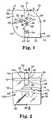
- FIG. 1is a top view of a closed article according to one aspect of the present invention.
- FIG. 2is a side elevation of FIG. 1 .
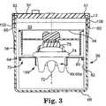
- FIG. 3is side section view taken at approximately 3 - 3 of FIG. 2 .
- FIG. 4is a perspective view showing a tamper resistant tag.
- FIG. 5is a perspective view of a body component.
- FIG. 6is a perspective view of a shelf component.
- FIG. 6 ais a perspective view of an alternative embodiment of a shelf component.
- FIG. 6 bis a perspective view of an alternative embodiment of a shelf component.
- FIG. 6 cis a perspective view of an alternative embodiment of the shelf component.
- FIG. 7is a perspective view of a bottom portion of a cap.
- FIG. 8is an exploded perspective view of the valve retainer with an aortic valve mounted in a holder several components.
- FIG. 9is an exploded perspective view of the valve retainer with an aortica mitral valve mounted in a holder.
- FIGSare not necessarily to scale.
- the present inventionprovides a solution to packaging a prosthetic device in a sterile condition for shipment and storage prior to application to a patient.
- FIG. 1shows a top view of the present invention.
- the present apparatus 10is a system for suspending a prosthetic valve in a sterile solution in a container to protect the valve from damage and contamination during shipment handling and storage.
- the containeris shown as jar 56 ( FIG. 2 ) with a removable lid 12 sealingly attached.
- the lid 12has a top side 14 and a grip surface 18 .
- a torque enhancing shape 16is preferably formed in the lid 12 .
- the torque enhancing shape 16has a first projection 20 on the grip surface 18 defining a first flat 22 and a first point 23 .
- a second projection 24is disposed on the grip surface 18 at an angular separation from the first projection 20 .
- the second projection 24has a second flat 26 and a second point 27 .
- the flats 22 , 26are orientated at a tangent to the circular grip surface 18 .
- the first projection 20 and the second projection 24enhance the application of torque, by a surgery worker (not shown), to turn and open the lid 12 .
- an opening force at arrow Ais easier to apply than the same force applied at Arrow B.
- a first fill hole 28is formed in the lid 12 to provide access through the top 14 into the storage chamber 30 ( FIG. 3 ).
- a fold over first tab 32is formed on the top 14 adjacent the first fill hole 28 .
- the first tab 32has a bottom surface 36 and a perimeter comprising hinge side 34 on the lid 12 , a leading edge 38 and two side edges 40 , 42 .
- the hinge side 34is on the lid 12 adjacent the first fill hole 28 .
- a second fill hole 44 on the top 14is shown closed by a second tab 46 sealingly connected to the top 14 .
- the second tab 46is attached by welding the perimeter of the second tab 46 to the top 14 to close the second hole 44 .
- the second tab 46is similar to the first tab 32 .
- the second tab 46has a hinge side 34 on the top 14 , a top side 48 , a leading edge 38 and two side edges 40 , 42 .
- the second tab 46is folded over to cover the second fill hole 44 and sealingly attached to the top 14 .
- the tabs 32 , 46may also be attached to the top 14 by inserting a seal plug, welding or epoxy or the like.
- the lid 12may be made of plastic or metal.
- a tamper evident seal 50 on the lid 12comprises a first perforated strip 51 and a second perforated strip 52 .
- the perforated strips 51 , 52are adhesively attached to the lid 12 on the lid end 54 and the jar 56 on the jar end 58 ( FIG. 2 ).
- a perforation 60 on each strip 51 , 52is aligned at a bottom edge 62 of the lid 12 .
- the jar 56has a sidewall 64 , an open top 66 and a closed bottom 68 forming an open cylinder shaped storage chamber 30 sealed with the lid 12 .
- the lid 12is removably attached to the open top 66 .
- the storage chamber 30has an axis 72 ( FIG. 3 ).
- a retainer 70( FIG. 3 ) is positioned in the jar 56 .
- the retainer 70( FIG. 3 ) has a valve pocket 189 suspended between the top 66 , the bottom 68 and in spaced relation to the sidewall 64 of the jar 56 .
- the retainer 70FIG. 3 ) prevents damage and contamination to the valve 69 from moving around and bumping against the jar 56 .
- the retainer 70 ( FIG. 3 )holds the valve 69 submerged in a sterile solution 73 in the jar 56 .
- the valve 69has a sewing ring 74 attached thereto.
- a valve holder 75is removably associated with the sewing ring
- the retainer 70has a body 82 , a shelf 80 and a cap 84 .
- the retainer 70is a support structure surrounding the storage chamber 30 .
- the retainer 70extends from the bottom 68 to the top 66 of the jar 56 .
- the shelf 80 on the retainer 70is mounted in the storage chamber 30 in a position between the top 66 and the bottom 68 of the jar 56 .
- the cap 84is attached to the body adjacent the shelf 80 .
- the valveis held in a fixed position between the shelf 80 and the cap 84 .
- the retainer 70is in the jar 56 to support the valve pocket 189 in a position spaced from the sidewall 64 and between the top 66 and bottom 68 of the jar 56 during shipment, handling and storage.
- the valve 69sits in the valve pocket 189 with the sewing ring 74 on the shelf 80 .
- the first and second perforated strips 51 , 52have the perforation 60 aligned with the bottom edge 62 of the lid 12 .
- an adhesive 98is placed on the inside 100 of the lid end 54 to thereby attach the lid end 54 of each perforated strip 51 , 52 to the lid 12 .
- the perforated strips 51 , 52further comprise ajar end 58 having adhesive 98 on the inside 100 to adhere the jar end 58 to the jar 56 .
- a flag section 102 between the lid end 54 and the perforations 60is masked during manufacture to prevent adhesive 98 from covering the flag section 102 of the perforations 60 .
- Each perforated strip 51 , 52has an outside 106 for printing information about the seal or the contents of the jar.
- the perforated strips 51 , 52are made from a flexible paper or plastic material having a coloring to contrast with the lid 12 and the jar 56 .
- One preferred embodimentis a panatone yellow strip.
- Product labels on the lid 12 and jar 56may be placed over the ends 54 , 58 .
- the body 82has a base 108 , a ledge 110 and an upper wall 114 .
- the ledgeis formed between the base 108 and the upper wall 114 .
- the base 108has a first end 109 on the bottom 68 of the jar 56 and a second end 112 on the ledge 110 .
- the upper wall 114extends from the ledge 110 opposite the base 108 to a lid end 116 .
- the baseis on the jar bottom 68 and the lid end 116 is adjacent to and may bear against the lid 12 .
- the ledge 110is between the base 108 and the lid end 116 .
- the upper wall 114has a valve side 118 and a jar side 120 .
- the upper wall 114has a lock guide 121 formed therein for engaging the cap 84 and guiding the cap 84 to a locked position.
- the lock guide 121has a cam surface 122 formed at an angle to the ledge 110 to guide the cap 84 toward the ledge 110 and into a locked position 115 ( FIG. 3 ).
- the upper wall 114has a lock adapter 123 formed therein for capturing and removably retaining the cap on the body 82 .
- a locating slot 124is formed in the upper wall 114 .
- the locating slot 124opens at the lid end 116 and extends through the upper wall 114 to a position adjacent the ledge 110 .
- the locating slot 124has an open end 126 , a closed end 128 and two spaced edges 130 , 131 forming a slot 124 extending from adjacent the ledge 110 and opening at the lid end 116 for engaging the shelf 80 .
- the present inventionincludes indicia or identification means for the valves.
- the upper wall 114has a tag pocket 132 on the jar side 120 for retaining a serial number tag 142 on the body 82 .
- the tag pocket 132has a bottom 134 , a first side 136 and second side 138 .
- the tag pocket 132is open between the first side 136 and the second side 138 to allow the serial number tag 142 to be read from outside the body 82 .
- the tag pocket 132has open top 140 for insertion and removal of the serial number tag 142 .
- the serial number tag 142has a tether 145 attached between the tag 142 and the body 82 .
- a tag post 144is formed on the body 82 adjacent the open top 140 to keep the serial number tag in the pocket 132 .
- the tag posthas a spacer 146 and a lip 148 .
- the tag 142is placed in the tag pocket 132 and is captured between the tag pocket bottom 134 and the tag post lip 148 .
- the serial number tag 142may have a numeric identification embossed thereon, a barcode, or other identifying marks.
- the serial number tag 142may alternatively be a RF Id or other passive or active electronic marker used to identify objects.
- the identification means or indiciamay comprise a bar code, that is preferably not physically attached to the valve. Other embodiments may include attaching a tag to hooks or pegs on the retainer.
- the identification meansmay comprise engraving, etching, embossing or printing indicia such as a serial number or bar code directly on the retainer or valve holder.
- a shelf 80 having an aortic valve configuration for supporting an aortic style valve 69( FIG. 8 ) is shown.
- the shelf 80has a support ring 150 , an outer flange 152 and an inner flange 154 .
- the support ring 150has an inside 156 , an outside 158 , a top edge 161 and a bottom edge 162 .
- the support ring 150is cylindrical.
- the support ring 150is axially aligned in the storage chamber 30 .
- the outer flange 152has inner edge 165 on the outside 158 of the support ring 150 , a top 151 and a bottom 153 .
- the outer flange 152extends outwardly from the support ring 150 .
- the outer flange 152is disposed between the valve pocket 189 and the jar 56 .
- the outer flange 152has a plurality of drain holes 160 formed therein by drilling or molding. Each drain hole 160 has a periphery 163 defined by the edge of the drain hole 160 .
- the drain holes 160extend from the top 151 to the bottom 153 of the outer flange 152 .
- the inner flange 154forms a bottom to the valve pocket 189 .
- Inner flange 154has an outer edge 178 on the inside 156 of the support ring 150 adjacent the bottom edge 162 .
- the inner flange 154has a top 180 , a bottom 182 and a drain hole 184 .
- the drain hole 184has an edge 186 and an axis 188 .
- the inner flange 154 and the support ring 150form a valve pocket 189 on the shelf 80 .
- the valve 69is positioned in the valve pocket 189 to protect from damage.
- the configuration of FIG. 6illustrates the valve pocket 189 with the inner flange 154 acting as the bottom surface.
- the valve pocket 189is circumferentially surrounded by the support ring 150 .
- a locating tab 164extends from the outer edge 166 of the outer flange 152 .
- the locating tab 164is sized to slidably fit in the locating slot 124 in the upper wall 114 of the body 82 .
- a plurality of snap fingers 168are formed along the outer edge 166 .
- the snap fingers 168have a standoff 170 and a latch 172 .
- the latch 172is spaced from the bottom 153 of the outer flange 152 .
- the snap fingers 168are made of a resilient material such as PVC or other plastic compounds and may be molded as part of the shelf.
- FIG. 6 aA larger size aortic valve configuration shelf 80 is shown in FIG. 6 a .
- the shelf 80has an outer flange 152 located at the top edge 161 of the support ring 150 .
- the valve pocket 189is enlarged by a larger diameter support ring 150 and a more narrow outer flange 152 .
- the drain holes 160are formed adjacent to and with the snap fingers 168 .
- the drain hole periphery 163is part of the outer edge 166 .
- the snap fingers 168append from the drain hole periphery 163 .
- a drain channelis formed in the snap finger 168 to help drain liquid past the shelf 84 .
- the outer flange 152spaces the valve pocket 189 from the sidewall 64 and engages the body 82 by attaching to the ledge 110 .
- the support ring 150surrounds the valve pocket 189 .
- the outer edge 166bears against the body 82 ( FIG. 5 ) to space the support ring 150 away from the retainer.
- FIG. 6 bAn alternate preferred embodiment is shown in FIG. 6 b comprising a shelf 80 a having a mitral valve configuration.
- the mitral valve configuration for supporting a mitral style valve 69 ahas an open bottom on valve pocket 189 .
- the mitral valve configuration shelf 80 acomprises a support ring 150 and an outer flange 152 .
- the support ring 150has an inside 156 , an outside 158 , a top edge 161 and a bottom edge 162 .
- the outer flangefurther comprises an outer edge 166 , a top 151 and a bottom 153 .
- the outer flange 152is on the top edge 161 and extends outward to engage the body 82 .
- the support ring 150extends from the bottom 153 of the outer flange 152 .
- the outer flange 152has a plurality of drain holes 160 extending through the flange from the top 151 to the bottom 153 .
- Each drain hole 160has a periphery 163 defined by the edge of the drain hole 160 .
- the drain holes 160extend through the shelf 80 at the outer flange 152 .
- the drain holes 160may be round or other shapes to allow liquid to flow past the shelf 80 .
- the inside 156 of the support ring 150defines the valve pocket 189 for containing the portion of the valve 69 a hanging below the outer flange 152 .
- the mitral valve 69 a( FIG. 9 ) sits in the valve pocket 189 having the sewing ring 74 on the outer flange 152 and the leaflets extending or dangling between the sewing ring 74 and the bottom of the container, or away from the valve holder 75 .
- FIG. 6 cA larger size version of the mitral configuration shelf 80 a of FIG. 6 b is shown in FIG. 6 c having the outer flange 152 located at the top edge 161 of the support ring 150 .
- the larger valve sizerequires a larger diameter support ring 150 .
- the drain holes 160are formed in the outer flange 152 along the outer edge 166 .
- the snap fingers 168are formed in the periphery of the drain holes 160 .
- the drain hole periphery 163is part of the outer edge 166 defined by an indent or notch.
- the snap fingers 168append from the drain hole periphery 1653 .
- the cap 84has a shell 190 and a handle 192 .
- the cap 84is configured to removably attach to the upper wall 114 ( FIG. 5 ) by a quarter turn lock.
- the shell 190has a generally cylindrical shaped wall 194 having a top 198 and a bottom 200 .
- a lock 202is formed on the wall 194 .
- the lock 202is sized and positioned to slidably engage the body 82 ( FIG. 5 ) as is well known in the art of quarter turn fasteners.
- the cap 84may be attached to the lid 12 .
- the handle 192is radially attached to the shell 190 having a valve positioner 204 thereon.
- the valve positioner 204is attached to and spaced from the shell 190 .
- the handle 192has a first end 196 attached to the inside of the shell 190 .
- the valve positioner 204comprises a retaining ring 206 and a locating peg 208 .
- the locating peg 208has end 210 on the peg 208 .
- the valve positioner 204appends from the handle 192 to encircle and capture the handle adapter 76 ( FIG. 3 ) with the retaining ring 206 and the locating peg 208 .
- a retainer 70 for an aortic valve 69is shown in exploded perspective.
- the retainerhas a body 82 with a ledge 110 between the base 108 and upper wall 114 .
- the shelf 80is selected for the valve 69 size and configuration to be packaged.
- the aortic configuration shelf 80has an outer flange 152 , a support ring 150 and an inner flange 154 .
- the valve 69is attached to a sewing ring 74 on a valve holder 75 .
- the valve holder 75has a handle adapter 79 .
- the handle adapter 79has threaded hole 81 for threadably attaching a valve handle 212 to the valve holder 75 .
- the valve handle 212may be attached by threads, a snap fit or other releasable fastening method.
- the cap 84has a lock 202 and a valve positioner 204 .
- the shelfis attached to the ledge 110 by the snap fingers 168 and the locating tab 164 .
- the sewing ring 74is on the inner flange 154 .
- the valve 69is surrounded by the support ring 150 .
- the handle adapter 79is oriented toward the lid end 116 to engage the cap 84 and facilitate insertion of the handle 212 for removing the valve 69 from the retainer.
- the leaflets 149 of the valve 69are shown in aortic configuration positioned above the sewing ring 74 .
- the cap 84is concentrically inserted into the body at the second lid end 116 .
- the capengages the valve 69 at valve holder 75 with the valve positioner 204 ( FIG. 3 ).
- the valveis held between the shelf 80 and the cap 84 .
- the retainer 70 having the valve 69 insideis placed in the jar 56 .
- the handle 192is used to move the retainer 70 in and out of the jar 56 .
- the sterilizing solution 73drains through the drain holes 160 , 184 .
- the retainer 70may be used to hold the valve 69 outside of the jar prior to rinsing.
- the handle 192is turned a quarter turn to unlock the cap 84 from the body 82 .
- the cap 84is removed from the body 82 .
- the valve handle 212is screwed into the handle adapter 79 .
- the valve 69is removed from the system to be prepared for use.
- a retainer 70 and a valve 69 a having a mitral configurationis shown in exploded perspective.
- the retainer 70has a body 828 with a ledge 110 between the base 108 and the upper wall 114 .
- the shelf 80 ais selected for the mitral valve 69 a size and configuration to be packaged.
- the mitral configuration shelf 80 ahas an outer flange 152 and a support ring 150 .
- the mitral valve 69 ais attached to a sewing ring 74 on a valve holder 75 .
- the valve holder 75has a handle adapter 79 .
- the handle adapter 79has threaded hole 81 for threadably attaching a valve handle 212 to the valve holder 75 .
- the valve handle 212may be attached by threads, a snap fit or other releasable fastening method.
- the cap 84has a lock 202 and a valve positioner 204 .
- the shelf 80 ais attached to the ledge 110 by the snap fingers 168 and the locating tab 164 .
- the sewing ring 74is on the outer flange 152 .
- the leaflets 149 a of the valve 69 aare shown in mitral configuration positioned below the sewing ring 74 , away from the valve holder 75 .
- the valve 69 ais surrounded by the support ring 150 having the leaflets 149 a extending toward the base 108 .
- the handle adapter 79is oriented toward the lid end 116 to engage the cap 84 and facilitate insertion of the handle 212 for removing the valve 69 a from the retainer 70 .
- the cap 84is concentrically inserted into the body 82 at the lid end 116 .
- the cap 84engages the valve holder 75 with the valve positioner 204 .
- the mitral valve 69 ais held between the shelf 80 and the cap 84 .
- the retainer 70 having the valve 69 a inside
- the valve 69is manufactured having a sewing ring 74 circumferentially attached.
- a valve holder 75is removably attached to the sewing ring 74 .
- the valve 69is sterilized.
- the appropriate shelf 80is selected and sterilized with the body 82 , cap 84 , jar 56 and lid 12 .
- the shelf 80is inserted into the body 82 having the locating tab 164 in the slot 124 and the snap fingers 168 on the ledge 110 .
- the valve 69is placed in the valve pocket 189 resting on the sewing ring 74 and oriented with the handle adapter 796 toward the lid end 116 of the body 82 .
- the cap 84is concentrically inserted into the body 82 having the valve 69 between the shelf 80 and the cap 84 .
- the handle adapter 79is adjusted to engage the valve positioner 204 and the cap is turned to lock the cap 84 into the body 82 .
- the retainer 70 having the valve 69 contained thereinis placed in the jar 56 and the lid 12 is attached.
- the sterilized solutionis dispensed into the jar through one or more fill holes 28 , 44 to prevent spilling or splashing on a sealing surface of the lid 12 or the jar 56 .
- the respective tab 32 , 46 adjacent each fill holeis bent over to cover the fill hole and is ultrasonically welded to the lid 12 to seal the fill hole.
- the tamper evident seal 50is attached over the jar 56 and the lid 12 .
- the apparatus 10 with the valve 69 thereinis shipped to a facility for use in a patient.
- the jar 56is removed from the box and the outside of the jar 56 may be sterilized.
- the surgery workergrasps the jar 156 and applies an opening force (A) to a flat on the grip surface 18 .
- the tamper evident seal tears at the perforations 60 and the lid 12is unscrewed from the jar 56 .
- the retainer 70is removed from the jar allowing the sterilizing fluid 73 to drain through the drain holes 160 , 184 .
- the valve 69may be rinsed while held in the retainer 70 .
- the workergrasps the body 82 and the cap handle 192 and turns the cap handle 192 with respect to the body 82 .
- the cap 84releases from the body 82 and is removed.
- a valve handle 212is attached to the handle adapter 79 .
- the valve 69is removed from the retainer 70 attached to the handle 212 and further rinsed and prepared for use.
- valvessuch as aortic, tricuspid, pulmonic or mitral valves.
- the valveis preferably oriented in the jar retainer so that the handle can be conveniently attached directly to the valve holder, without having to re-orient the valve. This minimizes the chance for valve contamination during preparation for surgical implantation.
Landscapes
- Health & Medical Sciences (AREA)
- Cardiology (AREA)
- Oral & Maxillofacial Surgery (AREA)
- Transplantation (AREA)
- Engineering & Computer Science (AREA)
- Biomedical Technology (AREA)
- Heart & Thoracic Surgery (AREA)
- Vascular Medicine (AREA)
- Life Sciences & Earth Sciences (AREA)
- Animal Behavior & Ethology (AREA)
- General Health & Medical Sciences (AREA)
- Public Health (AREA)
- Veterinary Medicine (AREA)
- Prostheses (AREA)
Abstract
Description
Claims (26)
Priority Applications (1)
| Application Number | Priority Date | Filing Date | Title |
|---|---|---|---|
| US11/254,510US7699168B2 (en) | 2004-10-29 | 2005-10-20 | Heart valve storage and shipping retainer |
Applications Claiming Priority (2)
| Application Number | Priority Date | Filing Date | Title |
|---|---|---|---|
| US62348404P | 2004-10-29 | 2004-10-29 | |
| US11/254,510US7699168B2 (en) | 2004-10-29 | 2005-10-20 | Heart valve storage and shipping retainer |
Publications (2)
| Publication Number | Publication Date |
|---|---|
| US20060113207A1 US20060113207A1 (en) | 2006-06-01 |
| US7699168B2true US7699168B2 (en) | 2010-04-20 |
Family
ID=36566379
Family Applications (1)
| Application Number | Title | Priority Date | Filing Date |
|---|---|---|---|
| US11/254,510Active2029-02-08US7699168B2 (en) | 2004-10-29 | 2005-10-20 | Heart valve storage and shipping retainer |
Country Status (1)
| Country | Link |
|---|---|
| US (1) | US7699168B2 (en) |
Cited By (21)
| Publication number | Priority date | Publication date | Assignee | Title |
|---|---|---|---|---|
| US20100300045A1 (en)* | 2009-03-06 | 2010-12-02 | The Cleveland Clinic Foundation | Method for storing a medical device |
| US20110147251A1 (en)* | 2009-12-18 | 2011-06-23 | Edwards Lifesciences Corporation | Prosthetic heart valve packaging and deployment system |
| US20110198244A1 (en)* | 2010-02-15 | 2011-08-18 | Edwards Lifesciences Corporation | Prosthetic heart valve packaging system |
| US20110214398A1 (en)* | 2010-03-05 | 2011-09-08 | Edwards Lifesciences Corporation | Dry Prosthetic Heart Valve Packaging System |
| US8136659B2 (en)* | 2005-09-13 | 2012-03-20 | Sadra Medical, Inc. | Two-part package for medical implant |
| US20120290079A1 (en)* | 2011-05-12 | 2012-11-15 | Edwards Lifesciences Corporation | Mitral heart valve holder and storage system |
| US20130118949A1 (en)* | 2011-11-15 | 2013-05-16 | Boston Scientific Scimed, Inc. | Dual sterilization containment vessel |
| US20140107767A1 (en)* | 2012-10-12 | 2014-04-17 | St. Jude Medical, Cardiology Division, Inc. | Valve holder and loading integration |
| US9498317B2 (en) | 2010-12-16 | 2016-11-22 | Edwards Lifesciences Corporation | Prosthetic heart valve delivery systems and packaging |
| US10245136B2 (en) | 2016-05-13 | 2019-04-02 | Boston Scientific Scimed Inc. | Containment vessel with implant sheathing guide |
| US10350047B2 (en) | 2015-09-02 | 2019-07-16 | Edwards Lifesciences Corporation | Method and system for packaging and preparing a prosthetic heart valve and associated delivery system |
| US10357351B2 (en) | 2015-12-04 | 2019-07-23 | Edwards Lifesciences Corporation | Storage assembly for prosthetic valve |
| US10631968B2 (en) | 2017-03-06 | 2020-04-28 | Edwards Lifesciences Corporation | Humidity-management packaging systems and methods |
| US11020561B2 (en) | 2016-04-22 | 2021-06-01 | Hollister Incorporated | Medical device package with a twist cap |
| US11103676B2 (en) | 2016-04-22 | 2021-08-31 | Hollister Incorporated | Medical device package with flip cap having a snap fit |
| US11141562B2 (en) | 2017-02-21 | 2021-10-12 | Hollister Incorporated | Medical device package with flip cap having a snap fit |
| US20220151759A1 (en)* | 2019-08-02 | 2022-05-19 | Edwards Lifesciences Corporation | Prosthetic heart valve packaging |
| US11666730B2 (en) | 2017-12-08 | 2023-06-06 | Hollister Incorporated | Package for medical device for ergonomic device removal |
| US11771865B2 (en) | 2017-10-25 | 2023-10-03 | Hollister Incorporated | Caps for catheter packages |
| US12350139B2 (en) | 2021-01-21 | 2025-07-08 | Edwards Lifesciences Corporation | Systems and methods for holding prosthetic implants |
| US12433709B2 (en) | 2020-09-04 | 2025-10-07 | Hollister Incorporated | Medical device package with first use indicator label |
Families Citing this family (9)
| Publication number | Priority date | Publication date | Assignee | Title |
|---|---|---|---|---|
| WO2008089365A2 (en)* | 2007-01-19 | 2008-07-24 | The Cleveland Clinic Foundation | Method for implanting a cardiovascular valve |
| US20090266728A1 (en)* | 2008-04-25 | 2009-10-29 | Warsaw Orthopedic, Inc. | Medical device tracking system with tray and method |
| US9221563B2 (en) | 2011-06-09 | 2015-12-29 | DePuy Synthes Products, Inc. | Anodizing container |
| US11284984B2 (en) | 2017-05-02 | 2022-03-29 | Medtronic Vascular, Inc. | Assemblies and methods of sterilizing a wet stored prosthetic heart valve |
| CN110603205B (en)* | 2017-05-02 | 2022-08-09 | 美敦力瓦斯科尔勒公司 | Packaging for dry tissue prosthetic heart valves |
| WO2019161186A1 (en)* | 2018-02-15 | 2019-08-22 | Spinal Balance, Inc. | Protective container for sterilized medical implants |
| IT201800004148A1 (en)* | 2018-03-30 | 2019-09-30 | Alchilife S R L | MEDICAL DEVICE FOR THE PRESERVATION OF EXPLANTED CORNEE |
| JP7138928B2 (en)* | 2018-08-22 | 2022-09-20 | 株式会社サンメディカル技術研究所 | Aortic valve assessment aid |
| CN111166492B (en)* | 2020-03-04 | 2025-06-27 | 上海纽脉医疗科技有限公司 | Artificial heart valve support frame and packaging device |
Citations (14)
| Publication number | Priority date | Publication date | Assignee | Title |
|---|---|---|---|---|
| US4211325A (en)* | 1979-06-07 | 1980-07-08 | Hancock Laboratories, Inc. | Heart valve holder |
| US4750619A (en) | 1987-08-10 | 1988-06-14 | Osteonics Corp. | Package with tray for securing and presenting a sterile prosthetic implant element |
| US5720391A (en) | 1996-03-29 | 1998-02-24 | St. Jude Medical, Inc. | Packaging and holder for heart valve prosthesis |
| US5823342A (en) | 1997-11-14 | 1998-10-20 | Sulzer Carbomedics Inc. | Packaging for mitral or aortic heart valve device |
| US5960956A (en) | 1997-02-19 | 1999-10-05 | St. Jude Medical, Inc. | Storage container |
| US6199696B1 (en)* | 1999-05-26 | 2001-03-13 | Sulzer Carbomedics Inc. | Shock resistant packaging for a prosthetic heart valve |
| US6416547B1 (en)* | 1999-10-06 | 2002-07-09 | Edwards Lifesciences Corporation | Heart valve carrier and rinse cage |
| US20020161431A1 (en)* | 2000-07-27 | 2002-10-31 | Robert Stobie | Method for retrofitting a heart valve holder |
| US20030070944A1 (en)* | 2000-09-12 | 2003-04-17 | Alok Nigam | System for packaging and handling an implant and method of use |
| US6572819B1 (en)* | 1996-06-28 | 2003-06-03 | Johnson & Johnson Medical, Inc. | Instrument sterilization container having improved drainage and support for an instrument mat |
| US6702255B2 (en) | 2001-11-08 | 2004-03-09 | Edwards Lifesciences Corporation | H-shape duckbill hemostasis valve assembly including guide wire seal |
| US6723122B2 (en) | 2001-08-30 | 2004-04-20 | Edwards Lifesciences Corporation | Container and method for storing and delivering minimally-invasive heart valves |
| US6908113B2 (en)* | 2001-08-15 | 2005-06-21 | Laboratories Merck Sharp And Dohme-Chibret, Snc | Tamper-evident label |
| US6916547B2 (en) | 2002-02-01 | 2005-07-12 | Awi Licensing Company | Multi-functional unsaturated polyester polyols |
- 2005
- 2005-10-20USUS11/254,510patent/US7699168B2/enactiveActive
Patent Citations (14)
| Publication number | Priority date | Publication date | Assignee | Title |
|---|---|---|---|---|
| US4211325A (en)* | 1979-06-07 | 1980-07-08 | Hancock Laboratories, Inc. | Heart valve holder |
| US4750619A (en) | 1987-08-10 | 1988-06-14 | Osteonics Corp. | Package with tray for securing and presenting a sterile prosthetic implant element |
| US5720391A (en) | 1996-03-29 | 1998-02-24 | St. Jude Medical, Inc. | Packaging and holder for heart valve prosthesis |
| US6572819B1 (en)* | 1996-06-28 | 2003-06-03 | Johnson & Johnson Medical, Inc. | Instrument sterilization container having improved drainage and support for an instrument mat |
| US5960956A (en) | 1997-02-19 | 1999-10-05 | St. Jude Medical, Inc. | Storage container |
| US5823342A (en) | 1997-11-14 | 1998-10-20 | Sulzer Carbomedics Inc. | Packaging for mitral or aortic heart valve device |
| US6199696B1 (en)* | 1999-05-26 | 2001-03-13 | Sulzer Carbomedics Inc. | Shock resistant packaging for a prosthetic heart valve |
| US6416547B1 (en)* | 1999-10-06 | 2002-07-09 | Edwards Lifesciences Corporation | Heart valve carrier and rinse cage |
| US20020161431A1 (en)* | 2000-07-27 | 2002-10-31 | Robert Stobie | Method for retrofitting a heart valve holder |
| US20030070944A1 (en)* | 2000-09-12 | 2003-04-17 | Alok Nigam | System for packaging and handling an implant and method of use |
| US6908113B2 (en)* | 2001-08-15 | 2005-06-21 | Laboratories Merck Sharp And Dohme-Chibret, Snc | Tamper-evident label |
| US6723122B2 (en) | 2001-08-30 | 2004-04-20 | Edwards Lifesciences Corporation | Container and method for storing and delivering minimally-invasive heart valves |
| US6702255B2 (en) | 2001-11-08 | 2004-03-09 | Edwards Lifesciences Corporation | H-shape duckbill hemostasis valve assembly including guide wire seal |
| US6916547B2 (en) | 2002-02-01 | 2005-07-12 | Awi Licensing Company | Multi-functional unsaturated polyester polyols |
Cited By (61)
| Publication number | Priority date | Publication date | Assignee | Title |
|---|---|---|---|---|
| US10370150B2 (en) | 2005-09-13 | 2019-08-06 | Boston Scientific Scimed Inc. | Two-part package for medical implant |
| US9393094B2 (en) | 2005-09-13 | 2016-07-19 | Boston Scientific Scimed, Inc. | Two-part package for medical implant |
| US8136659B2 (en)* | 2005-09-13 | 2012-03-20 | Sadra Medical, Inc. | Two-part package for medical implant |
| US8439188B2 (en)* | 2009-03-06 | 2013-05-14 | The Cleveland Clinic Foundation | Method for storing a bioabsorble medical device |
| US20100300045A1 (en)* | 2009-03-06 | 2010-12-02 | The Cleveland Clinic Foundation | Method for storing a medical device |
| US9295539B2 (en)* | 2009-12-18 | 2016-03-29 | Edwards Lifesciences Corporation | Prosthetic heart valve packaging and deployment methods |
| US9918836B2 (en) | 2009-12-18 | 2018-03-20 | Edwards Lifesciences Corporation | Prosthetic heart valve packaging and deployment methods |
| US20120150288A1 (en)* | 2009-12-18 | 2012-06-14 | Edwards Lifesciences Corporation | Prosthetic heart valve packaging and deployment methods |
| US11311378B2 (en) | 2009-12-18 | 2022-04-26 | Edwards Lifesciences Corporation | Prosthetic heart valve packaging and deployment systems |
| US20110147251A1 (en)* | 2009-12-18 | 2011-06-23 | Edwards Lifesciences Corporation | Prosthetic heart valve packaging and deployment system |
| US8869982B2 (en) | 2009-12-18 | 2014-10-28 | Edwards Lifesciences Corporation | Prosthetic heart valve packaging and deployment system |
| US10835378B2 (en) | 2009-12-18 | 2020-11-17 | Edwards Lifesciences Corporation | Prosthetic heart valve packaging and deployment systems |
| US8839957B2 (en)* | 2010-02-15 | 2014-09-23 | Michael C. Murad | Prosthetic heart valve packaging system |
| US20110198244A1 (en)* | 2010-02-15 | 2011-08-18 | Edwards Lifesciences Corporation | Prosthetic heart valve packaging system |
| US11911256B2 (en) | 2010-03-05 | 2024-02-27 | Edwards Lifesciences Corporation | Dry prosthetic heart valve packaging system |
| US20110214398A1 (en)* | 2010-03-05 | 2011-09-08 | Edwards Lifesciences Corporation | Dry Prosthetic Heart Valve Packaging System |
| US8679404B2 (en) | 2010-03-05 | 2014-03-25 | Edwards Lifesciences Corporation | Dry prosthetic heart valve packaging system |
| US10561486B2 (en) | 2010-03-05 | 2020-02-18 | Edwards Lifesciences Corporation | Dry prosthetic heart valve packaging system |
| US9937030B2 (en) | 2010-03-05 | 2018-04-10 | Edwards Lifesciences Corporation | Dry prosthetic heart valve packaging system |
| US9539080B2 (en) | 2010-03-05 | 2017-01-10 | Edwards Lifesciences Corporation | Dry prosthetic heart valve packaging system |
| US11027870B2 (en) | 2010-12-16 | 2021-06-08 | Edwards Lifesciences Corporation | Prosthetic heart valve delivery systems and packaging |
| US9498317B2 (en) | 2010-12-16 | 2016-11-22 | Edwards Lifesciences Corporation | Prosthetic heart valve delivery systems and packaging |
| US10772725B2 (en) | 2011-05-12 | 2020-09-15 | Edwards Lifesciences Corporation | Mitral heart valve storage and handling system |
| US8968394B2 (en)* | 2011-05-12 | 2015-03-03 | Edwards Lifesciences Corporation | Mitral heart valve holder and storage system |
| US20120290079A1 (en)* | 2011-05-12 | 2012-11-15 | Edwards Lifesciences Corporation | Mitral heart valve holder and storage system |
| US11678981B2 (en) | 2011-05-12 | 2023-06-20 | Edwards Lifesciences Corporation | Mitral heart valve storage and handling system |
| US9861478B2 (en) | 2011-05-12 | 2018-01-09 | Edwards Lifesciences Corporation | Methods of deploying a mitral heart valve |
| US20130118949A1 (en)* | 2011-11-15 | 2013-05-16 | Boston Scientific Scimed, Inc. | Dual sterilization containment vessel |
| US9707077B2 (en) | 2011-11-15 | 2017-07-18 | Boston Scientific Scimed Inc. | Dual sterilization containment vessel |
| US8851286B2 (en)* | 2011-11-15 | 2014-10-07 | Boston Scientific Scimed Inc. | Dual sterilization containment vessel |
| US10849744B2 (en) | 2011-11-15 | 2020-12-01 | Boston Scientific Scimed, Inc. | Dual sterilization containment vessel |
| US9295549B2 (en)* | 2012-10-12 | 2016-03-29 | St. Jude Medical, Cardiology Division, Inc. | Valve holder and loading integration |
| US10022211B2 (en) | 2012-10-12 | 2018-07-17 | St. Jude Medical, Cardiology Division, Inc. | Valve holder and loading integration |
| US20140107767A1 (en)* | 2012-10-12 | 2014-04-17 | St. Jude Medical, Cardiology Division, Inc. | Valve holder and loading integration |
| US11051925B2 (en) | 2015-09-02 | 2021-07-06 | Edwards Lifesciences Corporation | Method and system for packaging and preparing a prosthetic heart valve and associated delivery system |
| US10350047B2 (en) | 2015-09-02 | 2019-07-16 | Edwards Lifesciences Corporation | Method and system for packaging and preparing a prosthetic heart valve and associated delivery system |
| US12090036B2 (en) | 2015-12-04 | 2024-09-17 | Edwards Lifesciences Corporation | Storage assembly for prosthetic valve |
| US11273024B2 (en) | 2015-12-04 | 2022-03-15 | Edwards Lifesciences Corporation | Storage assembly for prosthetic valve |
| US10357351B2 (en) | 2015-12-04 | 2019-07-23 | Edwards Lifesciences Corporation | Storage assembly for prosthetic valve |
| US11020561B2 (en) | 2016-04-22 | 2021-06-01 | Hollister Incorporated | Medical device package with a twist cap |
| US11103676B2 (en) | 2016-04-22 | 2021-08-31 | Hollister Incorporated | Medical device package with flip cap having a snap fit |
| US12128191B2 (en) | 2016-04-22 | 2024-10-29 | Hollister Incorporated | Medical device package with a twist cap |
| US11833312B2 (en) | 2016-04-22 | 2023-12-05 | Hollister Incorporated | Medical device package with flip cap having a snap fit |
| US12290641B2 (en) | 2016-04-22 | 2025-05-06 | Hollister Incorporated | Medical device package with flip cap having a snap fit |
| US11813409B2 (en) | 2016-04-22 | 2023-11-14 | Hollister Incorporated | Medical device package with flip cap having a snap fit |
| US10245136B2 (en) | 2016-05-13 | 2019-04-02 | Boston Scientific Scimed Inc. | Containment vessel with implant sheathing guide |
| US11707599B2 (en) | 2017-02-21 | 2023-07-25 | Hollister Incorporated | Medical device package with twist-off cap |
| US11141562B2 (en) | 2017-02-21 | 2021-10-12 | Hollister Incorporated | Medical device package with flip cap having a snap fit |
| US12144935B2 (en) | 2017-02-21 | 2024-11-19 | Hollister Incorporated | Medical device package with flip cap having a snap fit |
| US11166801B2 (en) | 2017-03-06 | 2021-11-09 | Edwards Lifesciences Corporation | Humidity-management packaging systems and methods |
| US12383390B2 (en) | 2017-03-06 | 2025-08-12 | Edwards Lifesciences Corporation | Humidity-management packaging systems and methods |
| US11931237B2 (en) | 2017-03-06 | 2024-03-19 | Edwards Lifesciences Corporation | Humidity-management packaging systems and methods |
| US10631968B2 (en) | 2017-03-06 | 2020-04-28 | Edwards Lifesciences Corporation | Humidity-management packaging systems and methods |
| US12171954B2 (en) | 2017-10-25 | 2024-12-24 | Hollister Incorporated | Caps for catheter packages |
| US11771865B2 (en) | 2017-10-25 | 2023-10-03 | Hollister Incorporated | Caps for catheter packages |
| US12023452B2 (en) | 2017-12-08 | 2024-07-02 | Hollister Incorporated | Package for medical device for ergonomic device removal |
| US11666730B2 (en) | 2017-12-08 | 2023-06-06 | Hollister Incorporated | Package for medical device for ergonomic device removal |
| US12239522B2 (en)* | 2019-08-02 | 2025-03-04 | Edwards Lifesciences Corporation | Prosthetic heart valve packaging |
| US20220151759A1 (en)* | 2019-08-02 | 2022-05-19 | Edwards Lifesciences Corporation | Prosthetic heart valve packaging |
| US12433709B2 (en) | 2020-09-04 | 2025-10-07 | Hollister Incorporated | Medical device package with first use indicator label |
| US12350139B2 (en) | 2021-01-21 | 2025-07-08 | Edwards Lifesciences Corporation | Systems and methods for holding prosthetic implants |
Also Published As
| Publication number | Publication date |
|---|---|
| US20060113207A1 (en) | 2006-06-01 |
Similar Documents
| Publication | Publication Date | Title |
|---|---|---|
| US7699168B2 (en) | Heart valve storage and shipping retainer | |
| EP3136941B1 (en) | Endoscope support tray and method for storing and transporting endoscopes | |
| US8794442B2 (en) | Package structure for glass containers for pharmaceutical use | |
| US5720391A (en) | Packaging and holder for heart valve prosthesis | |
| US5823342A (en) | Packaging for mitral or aortic heart valve device | |
| US4211325A (en) | Heart valve holder | |
| US6472675B2 (en) | Container for storing and shipping needle cartridges | |
| US8662299B2 (en) | Surgical screw carrier and method compatible with sterilization | |
| JPH0592017A (en) | Package for storing artificial cardiac valve | |
| US12257139B2 (en) | Protective container for sterilized medical implants | |
| US6664555B2 (en) | Container for storing and shipping radioactive materials | |
| EP1324717A1 (en) | Package | |
| AU2001294477A1 (en) | Package | |
| KR20060019640A (en) | Baby Feeding Bottle | |
| US20050269231A1 (en) | Container for packaging and deploying devices | |
| EP4319687B1 (en) | Heart valve storage and shipping packaging | |
| JPS63289524A (en) | Contact lens package | |
| US20250186186A1 (en) | System and method for dry-packaged heart valve |
Legal Events
| Date | Code | Title | Description |
|---|---|---|---|
| AS | Assignment | Owner name:MEDTRONIC, INC.,MINNESOTA Free format text:ASSIGNMENT OF ASSIGNORS INTEREST;ASSIGNORS:RYAN, TIMOTHY R.;BERGIN, CATHY A.;REEL/FRAME:017548/0824 Effective date:20060207 Owner name:MEDTRONIC, INC., MINNESOTA Free format text:ASSIGNMENT OF ASSIGNORS INTEREST;ASSIGNORS:RYAN, TIMOTHY R.;BERGIN, CATHY A.;REEL/FRAME:017548/0824 Effective date:20060207 | |
| FEPP | Fee payment procedure | Free format text:PAYOR NUMBER ASSIGNED (ORIGINAL EVENT CODE: ASPN); ENTITY STATUS OF PATENT OWNER: LARGE ENTITY Free format text:PAYER NUMBER DE-ASSIGNED (ORIGINAL EVENT CODE: RMPN); ENTITY STATUS OF PATENT OWNER: LARGE ENTITY | |
| STCF | Information on status: patent grant | Free format text:PATENTED CASE | |
| FPAY | Fee payment | Year of fee payment:4 | |
| MAFP | Maintenance fee payment | Free format text:PAYMENT OF MAINTENANCE FEE, 8TH YEAR, LARGE ENTITY (ORIGINAL EVENT CODE: M1552) Year of fee payment:8 | |
| MAFP | Maintenance fee payment | Free format text:PAYMENT OF MAINTENANCE FEE, 12TH YEAR, LARGE ENTITY (ORIGINAL EVENT CODE: M1553); ENTITY STATUS OF PATENT OWNER: LARGE ENTITY Year of fee payment:12 |