US7698975B2 - Table saw with cutting tool retraction system - Google Patents
Table saw with cutting tool retraction systemDownload PDFInfo
- Publication number
- US7698975B2 US7698975B2US10/720,990US72099003AUS7698975B2US 7698975 B2US7698975 B2US 7698975B2US 72099003 AUS72099003 AUS 72099003AUS 7698975 B2US7698975 B2US 7698975B2
- Authority
- US
- United States
- Prior art keywords
- cutting tool
- blade
- motor
- table saw
- swing arm
- Prior art date
- Legal status (The legal status is an assumption and is not a legal conclusion. Google has not performed a legal analysis and makes no representation as to the accuracy of the status listed.)
- Expired - Fee Related, expires
Links
- 238000001514detection methodMethods0.000claimsabstractdescription21
- 230000007246mechanismEffects0.000claimsdescription16
- 238000006243chemical reactionMethods0.000claimsdescription15
- 230000000452restraining effectEffects0.000claimsdescription11
- 239000000463materialSubstances0.000description5
- 230000004044responseEffects0.000description4
- 229920003023plasticPolymers0.000description3
- 238000009987spinningMethods0.000description3
- 230000000007visual effectEffects0.000description3
- PXHVJJICTQNCMI-UHFFFAOYSA-NNickelChemical compound[Ni]PXHVJJICTQNCMI-UHFFFAOYSA-N0.000description2
- 239000002360explosiveSubstances0.000description2
- 239000004033plasticSubstances0.000description2
- VYZAMTAEIAYCRO-UHFFFAOYSA-NChromiumChemical compound[Cr]VYZAMTAEIAYCRO-UHFFFAOYSA-N0.000description1
- 239000011358absorbing materialSubstances0.000description1
- 230000004913activationEffects0.000description1
- 230000008901benefitEffects0.000description1
- 238000010276constructionMethods0.000description1
- 230000008878couplingEffects0.000description1
- 238000010168coupling processMethods0.000description1
- 238000005859coupling reactionMethods0.000description1
- 230000009849deactivationEffects0.000description1
- 238000005474detonationMethods0.000description1
- 238000010586diagramMethods0.000description1
- 239000006260foamSubstances0.000description1
- 239000000155meltSubstances0.000description1
- 229910052759nickelInorganic materials0.000description1
- 239000005060rubberSubstances0.000description1
- 229910001220stainless steelInorganic materials0.000description1
- 239000002023woodSubstances0.000description1
Images


Classifications
- F—MECHANICAL ENGINEERING; LIGHTING; HEATING; WEAPONS; BLASTING
- F16—ENGINEERING ELEMENTS AND UNITS; GENERAL MEASURES FOR PRODUCING AND MAINTAINING EFFECTIVE FUNCTIONING OF MACHINES OR INSTALLATIONS; THERMAL INSULATION IN GENERAL
- F16P—SAFETY DEVICES IN GENERAL; SAFETY DEVICES FOR PRESSES
- F16P3/00—Safety devices acting in conjunction with the control or operation of a machine; Control arrangements requiring the simultaneous use of two or more parts of the body
- F16P3/12—Safety devices acting in conjunction with the control or operation of a machine; Control arrangements requiring the simultaneous use of two or more parts of the body with means, e.g. feelers, which in case of the presence of a body part of a person in or near the danger zone influence the control or operation of the machine
- F16P3/14—Safety devices acting in conjunction with the control or operation of a machine; Control arrangements requiring the simultaneous use of two or more parts of the body with means, e.g. feelers, which in case of the presence of a body part of a person in or near the danger zone influence the control or operation of the machine the means being photocells or other devices sensitive without mechanical contact
- B—PERFORMING OPERATIONS; TRANSPORTING
- B23—MACHINE TOOLS; METAL-WORKING NOT OTHERWISE PROVIDED FOR
- B23D—PLANING; SLOTTING; SHEARING; BROACHING; SAWING; FILING; SCRAPING; LIKE OPERATIONS FOR WORKING METAL BY REMOVING MATERIAL, NOT OTHERWISE PROVIDED FOR
- B23D47/00—Sawing machines or sawing devices working with circular saw blades, characterised only by constructional features of particular parts
- B23D47/08—Sawing machines or sawing devices working with circular saw blades, characterised only by constructional features of particular parts of devices for bringing the circular saw blade to the workpiece or removing same therefrom
- B—PERFORMING OPERATIONS; TRANSPORTING
- B23—MACHINE TOOLS; METAL-WORKING NOT OTHERWISE PROVIDED FOR
- B23D—PLANING; SLOTTING; SHEARING; BROACHING; SAWING; FILING; SCRAPING; LIKE OPERATIONS FOR WORKING METAL BY REMOVING MATERIAL, NOT OTHERWISE PROVIDED FOR
- B23D59/00—Accessories specially designed for sawing machines or sawing devices
- B23D59/001—Measuring or control devices, e.g. for automatic control of work feed pressure on band saw blade
- B—PERFORMING OPERATIONS; TRANSPORTING
- B23—MACHINE TOOLS; METAL-WORKING NOT OTHERWISE PROVIDED FOR
- B23Q—DETAILS, COMPONENTS, OR ACCESSORIES FOR MACHINE TOOLS, e.g. ARRANGEMENTS FOR COPYING OR CONTROLLING; MACHINE TOOLS IN GENERAL CHARACTERISED BY THE CONSTRUCTION OF PARTICULAR DETAILS OR COMPONENTS; COMBINATIONS OR ASSOCIATIONS OF METAL-WORKING MACHINES, NOT DIRECTED TO A PARTICULAR RESULT
- B23Q11/00—Accessories fitted to machine tools for keeping tools or parts of the machine in good working condition or for cooling work; Safety devices specially combined with or arranged in, or specially adapted for use in connection with, machine tools
- B23Q11/0078—Safety devices protecting the operator, e.g. against accident or noise
- B23Q11/0092—Safety devices protecting the operator, e.g. against accident or noise actuating braking or stopping means
- B—PERFORMING OPERATIONS; TRANSPORTING
- B27—WORKING OR PRESERVING WOOD OR SIMILAR MATERIAL; NAILING OR STAPLING MACHINES IN GENERAL
- B27G—ACCESSORY MACHINES OR APPARATUS FOR WORKING WOOD OR SIMILAR MATERIALS; TOOLS FOR WORKING WOOD OR SIMILAR MATERIALS; SAFETY DEVICES FOR WOOD WORKING MACHINES OR TOOLS
- B27G19/00—Safety guards or devices specially adapted for wood saws; Auxiliary devices facilitating proper operation of wood saws
- B27G19/02—Safety guards or devices specially adapted for wood saws; Auxiliary devices facilitating proper operation of wood saws for circular saws
- Y—GENERAL TAGGING OF NEW TECHNOLOGICAL DEVELOPMENTS; GENERAL TAGGING OF CROSS-SECTIONAL TECHNOLOGIES SPANNING OVER SEVERAL SECTIONS OF THE IPC; TECHNICAL SUBJECTS COVERED BY FORMER USPC CROSS-REFERENCE ART COLLECTIONS [XRACs] AND DIGESTS
- Y10—TECHNICAL SUBJECTS COVERED BY FORMER USPC
- Y10S—TECHNICAL SUBJECTS COVERED BY FORMER USPC CROSS-REFERENCE ART COLLECTIONS [XRACs] AND DIGESTS
- Y10S83/00—Cutting
- Y10S83/01—Safety devices
- Y—GENERAL TAGGING OF NEW TECHNOLOGICAL DEVELOPMENTS; GENERAL TAGGING OF CROSS-SECTIONAL TECHNOLOGIES SPANNING OVER SEVERAL SECTIONS OF THE IPC; TECHNICAL SUBJECTS COVERED BY FORMER USPC CROSS-REFERENCE ART COLLECTIONS [XRACs] AND DIGESTS
- Y10—TECHNICAL SUBJECTS COVERED BY FORMER USPC
- Y10T—TECHNICAL SUBJECTS COVERED BY FORMER US CLASSIFICATION
- Y10T83/00—Cutting
- Y10T83/081—With randomly actuated stopping means
- Y10T83/088—Responsive to tool detector or work-feed-means detector
- Y10T83/089—Responsive to tool characteristic
- Y—GENERAL TAGGING OF NEW TECHNOLOGICAL DEVELOPMENTS; GENERAL TAGGING OF CROSS-SECTIONAL TECHNOLOGIES SPANNING OVER SEVERAL SECTIONS OF THE IPC; TECHNICAL SUBJECTS COVERED BY FORMER USPC CROSS-REFERENCE ART COLLECTIONS [XRACs] AND DIGESTS
- Y10—TECHNICAL SUBJECTS COVERED BY FORMER USPC
- Y10T—TECHNICAL SUBJECTS COVERED BY FORMER US CLASSIFICATION
- Y10T83/00—Cutting
- Y10T83/768—Rotatable disc tool pair or tool and carrier
- Y10T83/7684—With means to support work relative to tool[s]
- Y10T83/773—Work-support includes passageway for tool [e.g., slotted table]
Definitions
- the present inventionrelates to table saws and more particularly to a table saw with an improved retraction system for the saw blade.
- Table sawsare a type of woodworking machinery used to cut workpieces of wood, plastic, and other materials.
- Table sawsinclude a flat surface or table with a circular saw blade extending up through a slot in the table. A user slides a workpiece on the table against and past the blade while the blade is spinning to cut the workpiece. It is desirable to provide a system to retract the blade in response to detection of one or more conditions.
- a table saw having a cutting region for cutting workpiecesincludes a motor driving a movable cutting tool for cutting workpieces in the cutting region, a control system including a logic controller, a detection system adapted to detect one or more conditions between a person and the cutting tool, and a reaction system associated with the detection system and the cutting tool wherein the reaction system is configured to retract the cutting tool at least partially away from the cutting region and to disengage the motor driving the cutting tool upon detection of at least one of the conditions by the detection system.
- the motorindirectly drives the cutting tool so that the time to retract the cutting tool from the cutting region can be reduced.
- the driving engagement of the cutting toolcan be interrupted when the cutting tool is retracted.
- FIG. 1shows an exemplary table saw that incorporates the retraction system of the present invention.
- FIG. 2shows another exemplary table saw that incorporates the retraction system of the present invention.
- FIG. 3is a schematic block diagram of the table saw in accordance with the present invention.
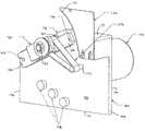
- FIG. 4is a fragmentary schematic perspective view of a table saw with a retraction system and with the blade removed to better show the system.
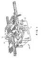
- FIG. 5is a fragmentary schematic side view of a table saw with a retraction system and with the blade in a cutting or operating position.
- FIG. 6is a fragmentary schematic side view of a table saw with a retraction system and with the blade in a retracted position.
- FIG. 1one type of table saw 10 is shown and it includes a support frame 20 on which is mounted a working table 24 .
- the table saw 10has a cutting assembly 130 which includes a motor 140 and a cutting tool 150 driven by the motor 140 (see FIG. 3 ).
- the working table 24has an elongated generally rectangular opening 26 through which the cutting tool or blade 150 can project.
- the working table 24may also have a blade guard 28 , desirably formed of a transparent plastic material, for covering the exposed portion of the saw blade 150 .
- a blade adjustment mechanism or handle 30is mounted to the front of the support frame 20 .
- the blade adjustment mechanism 30can vary the extent by which the blade 150 projects above the surface of the working table 24 and to vary the inclination of the blade 150 relative the surface of the working table 24 .
- FIG. 1For ease of reference but without limiting the scope of the claims, the present invention will be described in connection with a table saw 10 of the type shown in FIG. 1 . It is contemplated, however, that the features of the present invention will be equally applicable to the “contractors” type of table saw 10 depicted in FIG. 2 .
- This type of table saw 10includes, a working table 24 through which a blade 150 extends from beneath the table through an opening 26 .
- the table 24 and blade 150are supported by a frame 20 and legs 22 .
- the frame 20encloses the mechanics that support, position, and drive the blade 150 .
- a motor 140 to drive the blade 150can be positioned in or outside the frame 20 .
- a blade adjustment mechanismsuch as a handle 30 , is used to adjust the position of the blade 150 relative to the table 24 , for example, how far the blade 150 extends above the table 24 or how the blade 150 tilts relative to the top of the table 24 .
- the table saw 10includes a power source 32 , a cutting system 130 and a control system 40 .
- the control system 40includes a detection subsystem 50 , a logic controller 60 , and a reaction subsystem 70 .
- the detection system 50is adapted to detect one or more conditions such as the close proximity between a portion of the human body and the cutting tool 150 .
- the detection system 50may also be adapted to detect when the human body or a portion thereof such as a hand, is in close proximity to the opening 26 or the blade cover 28 .
- control system 40When the detection system 40 detects one or more conditions, the control system 40 is configured to retract the blade 150 from a position extending above the top of the table 24 to a position below the table top 24 .
- One embodiment of the control systemis described in U.S. Ser. No. 60/444,263 filed Jan. 31, 2003, the entire contents of which are incorporated herein by reference.
- the logic controller 60is configured to control the table saw in response to the inputs it receives.
- the logic controller 60may be adapted to receive inputs from a variety of sources including the detection subsystem 50 , the reaction subsystem 70 , and the cutting system 130 .
- the logic controller 60may also include one or more sensors adapted to monitor selected parameters of the table saw.
- the logic controller 60typically includes one or more instruments operable by a user to control the table saw 10 .
- the instrumentsmay include start/stop switches, speed controls, direction controls, etc.
- the logic controller 60may also be connected to receive the user's inputs via the various instruments as well as inputs from other sources (not shown) such as blade motion sensors, workpiece sensors, etc. to control the cutting system 130 and/or the reaction system 70 .
- the logic controller 60may have a predetermined response to the inputs received.
- the logic controller 60can activate various features of the reaction subsystem 70 depending on the detection signal received from the detection subsystem 50 .
- an output signal or series of signalsactivates at least one element within the reaction subsystem 70 .
- the logic controller 60can cause the reaction subsystem 70 to activate the retraction subsystem 76 , disable movement of the cutting blade 150 , activate a visual light 72 or audible sound 74 , or rapidly effectuate any combination thereof.
- the logic controller 60can also send a signal to the reaction subsystem 70 to activate the retraction system 76 , to provide the user with a visual signal 72 that a body part is in close proximity to the blade 150 , blade guard 28 , opening 26 , or another area near the blade 150 .
- the reaction subsystem 70is configured to retract the blade 150 .
- the reaction subsystem 70is configured to substantially simultaneously retract the blade 150 (move the blade to a position below the table top), disable a restraining mechanism 170 , as well as optionally providing a visual light 72 and/or an audible sound such as a beeper 74 .
- the table saw 10includes a suitable power source 32 to provide power to the cutting system 130 and the control system 40 .
- the power source 32may be an external power source such as line current, or an internal power source such as a battery.
- the power source 32may include a combination of both external and internal power sources.
- the power source 32may include two or more separate power sources, each adapted to power different portions of the table saw 10 .
- FIG. 4one embodiment of a table saw 10 with a reaction subsystem 70 that incorporates a retraction system 76 according to the present invention is shown.
- the blade 150can be retracted below the table 24 without moving the motor 140 .
- the energy or force to drop the blade 150 below the table 24is reduced, which should allow the blade 150 to move downward very rapidly and possibly at a velocity greater than the approach velocity of the user.
- the motor 140is not moving with the blade 150 , the energy required to be dissipated to stop the downward motion of the blade 150 is less, thus minimizing unwanted rebound of the blade 150 .
- the blade 150when the blade 150 is dropped (retracted), the blade 150 is no longer in driving engagement with the motor 140 . As a result, the blade 150 will stop spinning and the need to dissipate the energy of the spinning motor 140 is eliminated.
- the table saw 10includes a trunion 100 to carry the motor 140 , a riving knife 120 , and the retraction system 76 .
- the trunion 100includes a first side 102 , a second side 104 , a front 106 , a rear 108 , a top 110 , and a bottom 112 .
- the trunion 100also has an angled portion 114 that connects the top 110 with the front 106 and below which the blade 150 rests in the retracted position (See FIG. 6 ).
- the trunion 100can be adjusted up or down or at an angle with respect to the top of table 24 by use of the adjustment mechanism or handle 30 , as is known in the art. As a result, the blade 150 can be adjusted with respect to the top of the table 24 .
- the trunion 100also is provided with an upper stop 116 located on the first side of the trunion 102 where the angled portion of the trunion 114 connects the top of the trunion 110 .
- the upper stop 116provides a stop for a swing arm 160 to preclude further upward pivoting of the swing arm 160 and thus further upward movement of the blade 150 .
- the motor 140indirectly drives the blade 150 through an arbor 152 upon which the blade 150 is secured by a nut 154 or similar fastener.
- a drive 144connects a motor shaft 142 with the blade arbor 152 .
- the drive 144may be a belt, split-apart gear box, or other known driving mechanisms.
- the motor 140is shown as being mounted on a side of the trunion opposite the blade 150 with the motor shaft 142 extending through an opening of the trunion. It will be understood, however, that the motor 140 can be conveniently located so long as motor 140 indirectly drives the blade 150 so that as the blade 150 retracts the blade arbor 152 will not be driven by the motor 140 .
- the blade arbor 152is carried on the swing arm 160 , which has a first end 162 and a second end 166 with the first end 162 being pivotally connected 164 to the front portion of the trunion 106 .
- the pivotal connection 164can be implemented in any known fashion so long as the swing arm 160 is free to pivot from a blade operating position (shown in FIG. 5 ) to a blade retracted position (shown in FIG. 6 ).
- the swing arm 160is at an angle of about 27.degree. from the horizontal when the blade 150 is in the operating position. It is contemplated that the swing arm 160 can be provided at different suitable angles depending on the requirements of the table saw 10 and the construction of the trunion 100 .
- a restraining mechanism 170is operatively associated with the second end of the swing arm 166 to restrain the swing arm 160 from moving to the blade retracted position from the blade operating position. It will be appreciated that during operation of the blade 150 (i.e., cutting movement of the blade), the swing arm 160 will normally be urged in an upward direction. As a result, the restraining mechanism 170 need only provide sufficient force to retain the swing arm 160 and thus the blade 150 in the blade operating position, when the blade 150 is not moving.
- Suitable restraining mechanisms 170include, but are not limited to, a shear pin, a spring loaded ball within a detent in the trunion 100 such that the ball engages a detent in the second end of the swing arm, or vice versa, a fusible material such as a nickel chrome wire, stainless steel wire, etc such that the fusible material melts under a predetermined electrical current density, a magnetic solenoid that is demagnetized either upon electrical activation or electrical deactivation or similar apparatus to restrain the swing arm 160 from downward movement.
- the retraction system 76also includes an actuator 180 that contacts the second end of the swing arm 166 to provide a downward force sufficient to overcome the restraining force of the restraining mechanism 170 to allow the swing arm to swing downwardly or to push the swing arm in a downward direction.
- the actuator 180must provide a sufficient force to shear the pin and force the swing arm 160 in a downward direction.
- the actuator 180provides a force greater than the restraining mechanism 170 force such that the additional force aids in the downward movement of the swing arm 160 .
- the actuator 180may be activated or deactivated depending upon receiving a signal as an indication of detection of one or more conditions.
- the actuator 180may be any mechanism that can apply a force to the second end of the swing arm 166 sufficient to drive the swing arm 160 in a downward direction.
- the actuator 180is solenoid with a plunger such that when the solenoid is energized the plunger extends outward from the solenoid contacting a portion of the second end of the swing arm 166 to drive the swing arm 160 downward.
- the solenoidcould be configured such that upon deenergization of the solenoid, the plunger extends outward.
- the actuator 180may be an explosive charge.
- the explosive chargemay be provided in a cavity formed on a portion of the trunion 100 adjacent the second end of the swing arm 166 such that the detonation energy is forced against the second end of the swing arm 166 to drive the swing arm 160 in a downward direction.
- At least one lower stop 118is provided to contact and stop the downward movement of the swing arm 160 and thus the saw blade 150 at a retracted position below the top of the table 24 .
- the lower stop 118is located on the same side of the trunion 100 as the swing arm 160 and is positioned so that the blade 150 may retract a sufficient distance.
- the lower stop 118is located such that the swing arm 160 is at angular distance from the horizontal that is less than the angular distance of the swing arm 160 when the blade is in the operating position. For example, if the swing arm 160 is at 27° from the horizontal when the blade is in the operating position, then the swing arm 160 should be at an angular distance less than ⁇ 27° from the horizontal, e.g., about ⁇ 25°.
- the drive 144 coupling motor shaft 142 with the blade arbor 152will be disengaged (or loosened in the case of the belt) from the motor shaft 142 .
- the motor 140will not be driving the blade 150 when the blade 150 is in the blade retracted position.
- the swing armmoves or acts independently of the motor
- the swing armmay be accelerated in a downward direction faster than if the swing arm moved with the motor.
- the bladeshould be retracted from the operating position faster than if the swing arm moved with the motor.
- the cutting tool and/or swing armcan move independently of the motor which can remain stationary or move independently of the cutting tool and/or swing arm.
- the lower stop 118is formed of any of a number of impact-absorbing materials such as elastomeric materials, rubber, foams, plastics, etc. to minimize any upward rebound or bounce of the swing arm 160 , which might cause the blade 150 to extend above the table top 24 .
- the riving knife 120is provided at the rear of the trunion 108 and it extends upward from the top of the trunion 110 .
- the riving knife 120is secured in position to act as a shield for the rear portion of the blade 150 .
- the riving knife 120has a front portion 122 adjacent and spaced from the blade 150 .
- the riving knife 120is stationary with respect to the blade 150 .
- the top of the front portion of the riving knife 122follows the contour of the blade 150 but it is rearwardly tapered to allow the blade 150 to retract without contacting the riving knife 122 .
- the present inventionis applicable to table saws and provides a control system wherein a cutting tool is retracted upon the occurrence of a specified one or more conditions, such as when it is detected that a portion of a human body is in proximity with the cutting tool.
Landscapes
- Engineering & Computer Science (AREA)
- Mechanical Engineering (AREA)
- Life Sciences & Earth Sciences (AREA)
- General Engineering & Computer Science (AREA)
- Wood Science & Technology (AREA)
- Forests & Forestry (AREA)
- Sawing (AREA)
Abstract
Description
Claims (10)
Priority Applications (5)
| Application Number | Priority Date | Filing Date | Title |
|---|---|---|---|
| US10/720,990US7698975B2 (en) | 2003-01-31 | 2003-11-24 | Table saw with cutting tool retraction system |
| AU2004231257AAU2004231257A1 (en) | 2003-11-24 | 2004-11-23 | Table saw with cutting tool retraction system |
| TW93135976ATW200533491A (en) | 2003-11-24 | 2004-11-23 | Table saw with cutting tool retraction system |
| EP20040027880EP1533092A1 (en) | 2003-11-24 | 2004-11-24 | Table saw with cutting tool retraction system |
| CNA2004101047603ACN1626301A (en) | 2003-11-24 | 2004-11-24 | Table saw with cutting tool retraction system |
Applications Claiming Priority (2)
| Application Number | Priority Date | Filing Date | Title |
|---|---|---|---|
| US44426303P | 2003-01-31 | 2003-01-31 | |
| US10/720,990US7698975B2 (en) | 2003-01-31 | 2003-11-24 | Table saw with cutting tool retraction system |
Publications (2)
| Publication Number | Publication Date |
|---|---|
| US20040159198A1 US20040159198A1 (en) | 2004-08-19 |
| US7698975B2true US7698975B2 (en) | 2010-04-20 |
Family
ID=34435831
Family Applications (1)
| Application Number | Title | Priority Date | Filing Date |
|---|---|---|---|
| US10/720,990Expired - Fee RelatedUS7698975B2 (en) | 2003-01-31 | 2003-11-24 | Table saw with cutting tool retraction system |
Country Status (5)
| Country | Link |
|---|---|
| US (1) | US7698975B2 (en) |
| EP (1) | EP1533092A1 (en) |
| CN (1) | CN1626301A (en) |
| AU (1) | AU2004231257A1 (en) |
| TW (1) | TW200533491A (en) |
Cited By (19)
| Publication number | Priority date | Publication date | Assignee | Title |
|---|---|---|---|---|
| US20110048205A1 (en)* | 2009-08-26 | 2011-03-03 | Credo Technology Corporation | Table saw with dust shield |
| US20110048190A1 (en)* | 2009-08-26 | 2011-03-03 | Credo Technology Corporation | Table saw with belt stop |
| US20110048188A1 (en)* | 2009-08-26 | 2011-03-03 | Credo Technology Corporation | Table saw with actuator module |
| US20110048194A1 (en)* | 2009-08-26 | 2011-03-03 | Credo Technology Corporation | Table saw with reset mechanism |
| US20110048195A1 (en)* | 2009-08-26 | 2011-03-03 | Credo Technology Corporation | Table saw with ratchet mechanism |
| US20110048207A1 (en)* | 2009-08-26 | 2011-03-03 | Credo Technology Corporation | Table saw with linkage drop system |
| US20110048189A1 (en)* | 2009-08-26 | 2011-03-03 | Credo Technology Corporation | Table saw with positive locking mechanism |
| US20110048193A1 (en)* | 2009-08-26 | 2011-03-03 | Credo Technology Corporation | Table saw with pressure operated actuator |
| US20110048196A1 (en)* | 2009-08-26 | 2011-03-03 | Credo Technology Corporation | Table saw with dropping blade |
| US20120227556A1 (en)* | 2009-08-26 | 2012-09-13 | Robert Bosch Gmbh | Table Saw with Actuator Reset Mechanism |
| US8490527B2 (en) | 2000-08-14 | 2013-07-23 | Sd3, Llc | Power equipment with systems to mitigate or prevent injury |
| US8578825B2 (en) | 2009-08-26 | 2013-11-12 | Robert Bosch Gmbh | Table saw with mechanical fuse |
| US20160167142A1 (en)* | 2014-12-15 | 2016-06-16 | Robert Bosch Gmbh | Ratchet and Release Mechanism for Swing Arm of Table Saw |
| US9511429B2 (en) | 2013-03-15 | 2016-12-06 | Robert BoschTool Corporation | Blade drop for power device and method of manufacturing thereof |
| US9517516B2 (en) | 2013-03-14 | 2016-12-13 | Robert Bosch Tool Corporation | Blade drop power tool with dust management |
| US9623498B2 (en) | 2003-12-31 | 2017-04-18 | Sd3, Llc | Table saws |
| US9969015B2 (en)* | 2015-03-12 | 2018-05-15 | Robert Bosch Tool Corporation | Power tool with protected coupling plate |
| US10384281B2 (en) | 2012-03-02 | 2019-08-20 | Sawstop Holding Llc | Actuators for power tool safety systems |
| US10632642B2 (en) | 2008-11-19 | 2020-04-28 | Power Tool Institute | Table saw with table sensor for sensing characteristic of workpiece |
Families Citing this family (94)
| Publication number | Priority date | Publication date | Assignee | Title |
|---|---|---|---|---|
| US7836804B2 (en) | 2003-08-20 | 2010-11-23 | Sd3, Llc | Woodworking machines with overmolded arbors |
| US6994004B2 (en) | 2000-09-29 | 2006-02-07 | Sd3, Llc | Table saw with improved safety system |
| US7171879B2 (en) | 2001-07-02 | 2007-02-06 | Sd3, Llc | Discrete proximity detection system |
| US7000514B2 (en) | 2001-07-27 | 2006-02-21 | Sd3, Llc | Safety systems for band saws |
| US7536238B2 (en) | 2003-12-31 | 2009-05-19 | Sd3, Llc | Detection systems for power equipment |
| US7290472B2 (en) | 2002-01-14 | 2007-11-06 | Sd3, Llc | Miter saw with improved safety system |
| US20150283630A1 (en)* | 2003-12-31 | 2015-10-08 | Sd3, Llc | Table saws with elevation mechanisms |
| US6857345B2 (en) | 2000-08-14 | 2005-02-22 | Sd3, Llc | Brake positioning system |
| US7024975B2 (en) | 2000-08-14 | 2006-04-11 | Sd3, Llc | Brake mechanism for power equipment |
| US7350445B2 (en) | 2003-08-20 | 2008-04-01 | Sd3, Llc | Brake cartridge for power equipment |
| US7225712B2 (en) | 2000-08-14 | 2007-06-05 | Sd3, Llc | Motion detecting system for use in a safety system for power equipment |
| US9724840B2 (en) | 1999-10-01 | 2017-08-08 | Sd3, Llc | Safety systems for power equipment |
| US7600455B2 (en) | 2000-08-14 | 2009-10-13 | Sd3, Llc | Logic control for fast-acting safety system |
| US7055417B1 (en) | 1999-10-01 | 2006-06-06 | Sd3, Llc | Safety system for power equipment |
| US20030056853A1 (en) | 2001-09-21 | 2003-03-27 | Gass Stephen F. | Router with improved safety system |
| US8061245B2 (en) | 2000-09-29 | 2011-11-22 | Sd3, Llc | Safety methods for use in power equipment |
| US20050041359A1 (en) | 2003-08-20 | 2005-02-24 | Gass Stephen F. | Motion detecting system for use in a safety system for power equipment |
| US7284467B2 (en) | 2000-08-14 | 2007-10-23 | Sd3, Llc | Apparatus and method for detecting dangerous conditions in power equipment |
| US7350444B2 (en) | 2000-08-14 | 2008-04-01 | Sd3, Llc | Table saw with improved safety system |
| US20040040426A1 (en)* | 2002-08-27 | 2004-03-04 | Gass Stephen F. | Miter saw with improved safety system |
| US7472634B2 (en) | 2003-08-20 | 2009-01-06 | Sd3, Llc | Woodworking machines with overmolded arbors |
| US20030131703A1 (en) | 2002-01-16 | 2003-07-17 | Gass Stephen F. | Apparatus and method for detecting dangerous conditions in power equipment |
| US7712403B2 (en) | 2001-07-03 | 2010-05-11 | Sd3, Llc | Actuators for use in fast-acting safety systems |
| US7100483B2 (en) | 2000-08-14 | 2006-09-05 | Sd3, Llc | Firing subsystem for use in a fast-acting safety system |
| US20020017179A1 (en)* | 2000-08-14 | 2002-02-14 | Gass Stephen F. | Miter saw with improved safety system |
| US9981326B2 (en)* | 2008-08-18 | 2018-05-29 | Sawstop Holding Llc | Table saw |
| US7077039B2 (en) | 2001-11-13 | 2006-07-18 | Sd3, Llc | Detection system for power equipment |
| US8065943B2 (en) | 2000-09-18 | 2011-11-29 | Sd3, Llc | Translation stop for use in power equipment |
| US7231856B2 (en) | 2001-06-13 | 2007-06-19 | Sd3, Llc | Apparatus and method for detecting dangerous conditions in power equipment |
| US7610836B2 (en) | 2000-08-14 | 2009-11-03 | Sd3, Llc | Replaceable brake mechanism for power equipment |
| US7827890B2 (en) | 2004-01-29 | 2010-11-09 | Sd3, Llc | Table saws with safety systems and systems to mount and index attachments |
| US7353737B2 (en) | 2001-08-13 | 2008-04-08 | Sd3, Llc | Miter saw with improved safety system |
| US7509899B2 (en) | 2000-08-14 | 2009-03-31 | Sd3, Llc | Retraction system for use in power equipment |
| US7098800B2 (en) | 2003-03-05 | 2006-08-29 | Sd3, Llc | Retraction system and motor position for use with safety systems for power equipment |
| US7137326B2 (en) | 2000-08-14 | 2006-11-21 | Sd3, Llc | Translation stop for use in power equipment |
| US9927796B2 (en) | 2001-05-17 | 2018-03-27 | Sawstop Holding Llc | Band saw with improved safety system |
| US8459157B2 (en) | 2003-12-31 | 2013-06-11 | Sd3, Llc | Brake cartridges and mounting systems for brake cartridges |
| US7197969B2 (en) | 2001-09-24 | 2007-04-03 | Sd3, Llc | Logic control with test mode for fast-acting safety system |
| US7210383B2 (en) | 2000-08-14 | 2007-05-01 | Sd3, Llc | Detection system for power equipment |
| DE10261743A1 (en)* | 2002-12-30 | 2004-07-22 | Robert Bosch Gmbh | Manual circular saw B27B |
| US6853300B2 (en)* | 2003-06-05 | 2005-02-08 | Kuo Lung Kuan | Saw cover safety sensing device |
| US7661614B2 (en)* | 2004-09-10 | 2010-02-16 | Fellowes Inc. | Shredder throat safety system |
| US8870106B2 (en)* | 2004-09-10 | 2014-10-28 | Fellowes, Inc. | Shredder with thickness detector |
| US7631822B2 (en) | 2004-09-10 | 2009-12-15 | Fellowes Inc. | Shredder with thickness detector |
| US7954737B2 (en) | 2007-10-04 | 2011-06-07 | Fellowes, Inc. | Shredder thickness with anti-jitter feature |
| US7628101B1 (en) | 2006-03-13 | 2009-12-08 | Power Tool Institute | Pyrotechnic drop mechanism for power tools |
| US8672247B2 (en) | 2005-07-11 | 2014-03-18 | Fellowes, Inc. | Shredder with thickness detector |
| US7841266B2 (en)* | 2007-01-22 | 2010-11-30 | Robert Bosch Gmbh | Proximity sensor for stationary power tools |
| US20090038456A1 (en)* | 2007-07-23 | 2009-02-12 | Wade Burch | Cut Finish Actuator For Table Saw |
| GB2451513B (en) | 2007-08-02 | 2012-04-18 | Acco Uk Ltd | A shredding machine |
| DE102007062256A1 (en)* | 2007-12-21 | 2009-06-25 | Robert Bosch Gmbh | circular saw |
| US8201761B2 (en) | 2009-01-05 | 2012-06-19 | Fellowes, Inc. | Thickness sensor based motor controller |
| US8430347B2 (en)* | 2009-01-05 | 2013-04-30 | Fellowes, Inc. | Thickness adjusted motor controller |
| US8091809B2 (en)* | 2009-03-24 | 2012-01-10 | Fellowes, Inc. | Shredder with jam proof system |
| US8205815B2 (en)* | 2009-05-15 | 2012-06-26 | Fellowes, Inc. | Paper alignment sensor arrangement |
| US8550387B2 (en)* | 2009-06-18 | 2013-10-08 | Tai Hoon K. Matlin | Restrictive throat mechanism for paper shredders |
| US8678305B2 (en)* | 2009-06-18 | 2014-03-25 | Fellowes, Inc. | Restrictive throat mechanism for paper shredders |
| US8245612B2 (en)* | 2009-08-26 | 2012-08-21 | Robert Bosch Gmbh | Table saw with swing arm support |
| US8316748B2 (en)* | 2009-08-26 | 2012-11-27 | Robert Bosch Gmbh | Table saw with alignment plate |
| TWI379752B (en) | 2009-12-30 | 2012-12-21 | Rexon Ind Corp Ltd | A saw machine riving knife adjustment mechanism |
| US8382019B2 (en) | 2010-05-03 | 2013-02-26 | Fellowes, Inc. | In-rush current jam proof sensor control |
| US8511593B2 (en) | 2010-05-28 | 2013-08-20 | Fellowes, Inc. | Differential jam proof sensor for a shredder |
| US8534174B2 (en) | 2010-09-27 | 2013-09-17 | Power Tool Institute | Pyrotechnic actuator and power cutting tool with safety reaction system having such pyrotechnic actuator |
| WO2014028664A2 (en) | 2012-08-17 | 2014-02-20 | Illinois Tool Works Inc. | Sample preparation saw |
| US20140182430A1 (en) | 2012-12-31 | 2014-07-03 | Robert Bosch Gmbh | Saw Device with Detection System |
| US10118308B2 (en) | 2013-10-17 | 2018-11-06 | Sawstop Holding Llc | Systems to mount and index riving knives and spreaders in table saws |
| EP3087301B1 (en)* | 2013-12-24 | 2018-02-21 | Robert Bosch GmbH | Power tool with ultrasonic sensor for sensing contact between an implement and an object |
| US10369642B2 (en) | 2015-03-12 | 2019-08-06 | Robert Bosch Tool Corporation | Power tool with protected circuit board orientation |
| US10105863B2 (en) | 2015-03-12 | 2018-10-23 | Robert Bosch Tool Corporation | System and method for object and operator profiling in an object detection system in a saw |
| US9868167B2 (en) | 2015-03-12 | 2018-01-16 | Robert Bosch Tool Corporation | Power tool with drop arm orbit bracket |
| US10493543B2 (en)* | 2015-03-12 | 2019-12-03 | Robert Bosch Tool Corporation | Power tool motor with reduced electrical noise |
| US10099399B2 (en) | 2015-03-12 | 2018-10-16 | Robert Bosch Tool Corporation | Object proximity detection in a saw |
| US10213853B2 (en) | 2015-03-12 | 2019-02-26 | Robert Bosch Tool Corporation | Power tool drop arm with offset ribbing |
| US9687922B2 (en) | 2015-03-12 | 2017-06-27 | Robert Bosch Tool Corporation | Power tool with cammed throat plate |
| US10189098B2 (en) | 2015-03-12 | 2019-01-29 | Robert Bosch Tool Corporation | Diagnostic and maintenance operation for a saw |
| US10799964B2 (en)* | 2015-03-12 | 2020-10-13 | Robert Bosch Tool Corporation | Table saw with pulley alignment mechanism |
| US9849527B2 (en) | 2015-03-12 | 2017-12-26 | Robert Bosch Tool Corporation | Power tool with lightweight actuator housing |
| US9868166B2 (en)* | 2015-03-12 | 2018-01-16 | Robert Bosch Tool Corporation | Power tool with pyrotechnic lockout |
| US10427227B2 (en) | 2015-03-12 | 2019-10-01 | Robert Bosch Tool Corporation | Drop arm reset method |
| US10786854B2 (en)* | 2015-03-12 | 2020-09-29 | Robert Bosch Tool Corporation | Table saw with electrically isolated arbor shaft |
| US9914239B2 (en) | 2015-03-12 | 2018-03-13 | Robert Bosch Tool Corporation | User interface system in a table saw |
| US10758989B2 (en) | 2015-03-12 | 2020-09-01 | Robert Bosch Tool Corporation | System and method for sensing cable fault detection in a saw |
| US10821529B2 (en) | 2015-03-12 | 2020-11-03 | Robert Bosch Tool Corporation | Power tool with improved belt tensioning |
| US10322522B2 (en) | 2015-03-12 | 2019-06-18 | Robert Bosch Tool Corporation | Electrical configuration for object detection system in a saw |
| US10071432B2 (en)* | 2015-03-12 | 2018-09-11 | Robert Bosch Tool Corporation | Power tool with arbor lock |
| CN105149684A (en)* | 2015-06-10 | 2015-12-16 | 江苏金飞达电动工具有限公司 | Movable overturning type fence device of electric tool |
| WO2017210091A1 (en) | 2016-05-31 | 2017-12-07 | Sd3, Llc | Detection systems for power tools with active injury mitigation technology |
| EP3318357B1 (en)* | 2016-11-04 | 2022-06-29 | Griggio S.r.l. in liquidazione | Cutting machine tool comprising a safety apparatus |
| IT201600123482A1 (en)* | 2016-12-06 | 2018-06-06 | Scm Group Spa | Machining unit with safety system and machine using this processing unit. |
| PL3403762T3 (en)* | 2017-05-19 | 2024-03-18 | Felder Kg | Machine tool with safety system |
| FR3073772B1 (en)* | 2017-11-23 | 2019-10-25 | Pellenc | ELECTRIC CUTTING TOOL WITH AUTOMATIC EMERGENCY STOP |
| CN112454565A (en)* | 2020-11-30 | 2021-03-09 | 东南大学扬州研究院 | Intelligent safety protection device of precise woodworking bench saw |
| CN114029548B (en)* | 2021-11-19 | 2024-07-05 | 江苏金飞达电动工具有限公司 | Accelerating disengaging device of cutting saw |
| US20230166343A1 (en)* | 2021-11-30 | 2023-06-01 | Nanjing Chervon Industry Co., Ltd. | Table tool and control method therefor |
Citations (24)
| Publication number | Priority date | Publication date | Assignee | Title |
|---|---|---|---|---|
| US2505958A (en)* | 1946-07-19 | 1950-05-02 | John O Grierson | Swinging power saw |
| US2674130A (en)* | 1952-12-19 | 1954-04-06 | Spychalla Alex | Portable machine tool |
| US2719547A (en)* | 1952-03-01 | 1955-10-04 | Gjerde Arne | Universally adjustable underbench saw |
| US2945516A (en)* | 1956-12-31 | 1960-07-19 | Yuba Cons Ind Inc | Tilting arbor table saw with coaxial control of elevation and tilt |
| US3013592A (en)* | 1959-03-23 | 1961-12-19 | Theodore G Ambrosio | Tilting table saw |
| GB1132708A (en) | 1965-10-15 | 1968-11-06 | Wilmot Breeden Ltd | Improvements in or relating to object detection systems |
| US3785230A (en)* | 1972-11-08 | 1974-01-15 | Lokey Tool Inc | Automatic safety brake for rotary blade equipment |
| US4276799A (en)* | 1979-04-18 | 1981-07-07 | Black & Decker Inc. | Power tool apparatus |
| US4334450A (en)* | 1979-06-20 | 1982-06-15 | Giben Impianti S.P.A. | Sawing machines |
| US4885965A (en)* | 1987-02-13 | 1989-12-12 | Ipco Corporation | Rotary saw for sectioning dental models |
| US5123317A (en) | 1991-03-20 | 1992-06-23 | Ryobi Motor Products Corp. | Support structure for a table saw blade assembly |
| US5219011A (en)* | 1990-09-18 | 1993-06-15 | Speck Dwight L | Hinge slotting machine |
| US20020017184A1 (en) | 2000-08-14 | 2002-02-14 | Gass Stephen F. | Table saw with improved safety system |
| US20020017175A1 (en) | 2000-08-14 | 2002-02-14 | Gass Stephen F. | Translation stop for use in power equipment |
| US20020017181A1 (en) | 2000-08-14 | 2002-02-14 | Gass Stephen F. | Retraction system for use in power equipment |
| US20020017183A1 (en) | 2000-08-14 | 2002-02-14 | Gass Stephen F. | Cutting tool safety system |
| US20020020271A1 (en) | 2000-08-14 | 2002-02-21 | Gass Stephen F. | Spring-biased brake mechanism for power equipment |
| US20020020263A1 (en) | 2000-08-14 | 2002-02-21 | Gass Stephen F. | Firing subsystem for use in a fast-acting safety system |
| US20020020265A1 (en)* | 2000-08-14 | 2002-02-21 | Gass Stephen F. | Translation stop for use in power equipment |
| US20020056350A1 (en) | 2000-09-29 | 2002-05-16 | Gass Stephen F. | Table saw with improved safety system |
| DE10107236A1 (en) | 2001-02-16 | 2002-09-26 | Christian Feldmann | Circular saw for carpenters is folded or pulled by a spring or other device for quick acceleration and a tripping device switches off the saw in emergencies |
| US20030000359A1 (en) | 2001-06-27 | 2003-01-02 | Eccardt Curtis J. | Table saw blade heel adjuster |
| US20030005588A1 (en) | 2001-07-03 | 2003-01-09 | Gass Stephen F. | Actuators for use in fast-acting safety systems |
| US20030090224A1 (en) | 2001-11-13 | 2003-05-15 | Gass Stephen F. | Detection system for power equipment |
- 2003
- 2003-11-24USUS10/720,990patent/US7698975B2/ennot_activeExpired - Fee Related
- 2004
- 2004-11-23TWTW93135976Apatent/TW200533491A/enunknown
- 2004-11-23AUAU2004231257Apatent/AU2004231257A1/ennot_activeAbandoned
- 2004-11-24EPEP20040027880patent/EP1533092A1/ennot_activeWithdrawn
- 2004-11-24CNCNA2004101047603Apatent/CN1626301A/enactivePending
Patent Citations (24)
| Publication number | Priority date | Publication date | Assignee | Title |
|---|---|---|---|---|
| US2505958A (en)* | 1946-07-19 | 1950-05-02 | John O Grierson | Swinging power saw |
| US2719547A (en)* | 1952-03-01 | 1955-10-04 | Gjerde Arne | Universally adjustable underbench saw |
| US2674130A (en)* | 1952-12-19 | 1954-04-06 | Spychalla Alex | Portable machine tool |
| US2945516A (en)* | 1956-12-31 | 1960-07-19 | Yuba Cons Ind Inc | Tilting arbor table saw with coaxial control of elevation and tilt |
| US3013592A (en)* | 1959-03-23 | 1961-12-19 | Theodore G Ambrosio | Tilting table saw |
| GB1132708A (en) | 1965-10-15 | 1968-11-06 | Wilmot Breeden Ltd | Improvements in or relating to object detection systems |
| US3785230A (en)* | 1972-11-08 | 1974-01-15 | Lokey Tool Inc | Automatic safety brake for rotary blade equipment |
| US4276799A (en)* | 1979-04-18 | 1981-07-07 | Black & Decker Inc. | Power tool apparatus |
| US4334450A (en)* | 1979-06-20 | 1982-06-15 | Giben Impianti S.P.A. | Sawing machines |
| US4885965A (en)* | 1987-02-13 | 1989-12-12 | Ipco Corporation | Rotary saw for sectioning dental models |
| US5219011A (en)* | 1990-09-18 | 1993-06-15 | Speck Dwight L | Hinge slotting machine |
| US5123317A (en) | 1991-03-20 | 1992-06-23 | Ryobi Motor Products Corp. | Support structure for a table saw blade assembly |
| US20020017184A1 (en) | 2000-08-14 | 2002-02-14 | Gass Stephen F. | Table saw with improved safety system |
| US20020017175A1 (en) | 2000-08-14 | 2002-02-14 | Gass Stephen F. | Translation stop for use in power equipment |
| US20020017181A1 (en) | 2000-08-14 | 2002-02-14 | Gass Stephen F. | Retraction system for use in power equipment |
| US20020017183A1 (en) | 2000-08-14 | 2002-02-14 | Gass Stephen F. | Cutting tool safety system |
| US20020020271A1 (en) | 2000-08-14 | 2002-02-21 | Gass Stephen F. | Spring-biased brake mechanism for power equipment |
| US20020020263A1 (en) | 2000-08-14 | 2002-02-21 | Gass Stephen F. | Firing subsystem for use in a fast-acting safety system |
| US20020020265A1 (en)* | 2000-08-14 | 2002-02-21 | Gass Stephen F. | Translation stop for use in power equipment |
| US20020056350A1 (en) | 2000-09-29 | 2002-05-16 | Gass Stephen F. | Table saw with improved safety system |
| DE10107236A1 (en) | 2001-02-16 | 2002-09-26 | Christian Feldmann | Circular saw for carpenters is folded or pulled by a spring or other device for quick acceleration and a tripping device switches off the saw in emergencies |
| US20030000359A1 (en) | 2001-06-27 | 2003-01-02 | Eccardt Curtis J. | Table saw blade heel adjuster |
| US20030005588A1 (en) | 2001-07-03 | 2003-01-09 | Gass Stephen F. | Actuators for use in fast-acting safety systems |
| US20030090224A1 (en) | 2001-11-13 | 2003-05-15 | Gass Stephen F. | Detection system for power equipment |
Cited By (37)
| Publication number | Priority date | Publication date | Assignee | Title |
|---|---|---|---|---|
| US8490527B2 (en) | 2000-08-14 | 2013-07-23 | Sd3, Llc | Power equipment with systems to mitigate or prevent injury |
| US10442108B2 (en)* | 2003-12-31 | 2019-10-15 | Sawstop Holding Llc | Table saws |
| US20170312837A1 (en)* | 2003-12-31 | 2017-11-02 | Sd3, Llc | Table saws |
| US9623498B2 (en) | 2003-12-31 | 2017-04-18 | Sd3, Llc | Table saws |
| US10632642B2 (en) | 2008-11-19 | 2020-04-28 | Power Tool Institute | Table saw with table sensor for sensing characteristic of workpiece |
| US9079258B2 (en) | 2009-08-26 | 2015-07-14 | Robert Bosch Gmbh | Table saw with belt stop |
| US10029386B2 (en) | 2009-08-26 | 2018-07-24 | Robert Bosch Tool Corporation | Table saw with positive locking mechanism |
| US20110048193A1 (en)* | 2009-08-26 | 2011-03-03 | Credo Technology Corporation | Table saw with pressure operated actuator |
| US20110048196A1 (en)* | 2009-08-26 | 2011-03-03 | Credo Technology Corporation | Table saw with dropping blade |
| US8250957B2 (en)* | 2009-08-26 | 2012-08-28 | Robert Bosch Gmbh | Table saw with linkage drop system |
| US20120227556A1 (en)* | 2009-08-26 | 2012-09-13 | Robert Bosch Gmbh | Table Saw with Actuator Reset Mechanism |
| US8291801B2 (en)* | 2009-08-26 | 2012-10-23 | Robert Bosch Gmbh | Table saw with ratchet mechanism |
| US8297159B2 (en)* | 2009-08-26 | 2012-10-30 | Robert Bosch Gmbh | Table saw with dropping blade |
| US8327744B2 (en)* | 2009-08-26 | 2012-12-11 | Robert Bosch Gmbh | Table saw with reset mechanism |
| US20110048207A1 (en)* | 2009-08-26 | 2011-03-03 | Credo Technology Corporation | Table saw with linkage drop system |
| US8578825B2 (en) | 2009-08-26 | 2013-11-12 | Robert Bosch Gmbh | Table saw with mechanical fuse |
| US8651001B2 (en) | 2009-08-26 | 2014-02-18 | Robert Bosch Gmbh | Table saw with reset mechanism |
| US8714061B2 (en)* | 2009-08-26 | 2014-05-06 | Robert Bosch Gmbh | Table saw with actuator reset mechanism |
| US20110048205A1 (en)* | 2009-08-26 | 2011-03-03 | Credo Technology Corporation | Table saw with dust shield |
| US20110048190A1 (en)* | 2009-08-26 | 2011-03-03 | Credo Technology Corporation | Table saw with belt stop |
| US20110048188A1 (en)* | 2009-08-26 | 2011-03-03 | Credo Technology Corporation | Table saw with actuator module |
| US10076796B2 (en) | 2009-08-26 | 2018-09-18 | Robert Bosch Tool Corporation | Table saw with dust shield |
| US20110048195A1 (en)* | 2009-08-26 | 2011-03-03 | Credo Technology Corporation | Table saw with ratchet mechanism |
| US20110048194A1 (en)* | 2009-08-26 | 2011-03-03 | Credo Technology Corporation | Table saw with reset mechanism |
| US20110048189A1 (en)* | 2009-08-26 | 2011-03-03 | Credo Technology Corporation | Table saw with positive locking mechanism |
| US9969013B2 (en) | 2009-08-26 | 2018-05-15 | Robert Bosch Tool Corporation | Table saw with actuator module |
| US10981238B2 (en) | 2009-10-02 | 2021-04-20 | Sawstop Holding Llc | Actuators for power tool safety systems |
| US11865631B2 (en) | 2009-10-02 | 2024-01-09 | Sawstop Holding Llc | Actuators for power tool safety systems |
| US12303989B2 (en) | 2009-10-02 | 2025-05-20 | Sawstop Holding Llc | Actuators for power tool safety systems |
| US10384281B2 (en) | 2012-03-02 | 2019-08-20 | Sawstop Holding Llc | Actuators for power tool safety systems |
| US9517516B2 (en) | 2013-03-14 | 2016-12-13 | Robert Bosch Tool Corporation | Blade drop power tool with dust management |
| US9511429B2 (en) | 2013-03-15 | 2016-12-06 | Robert BoschTool Corporation | Blade drop for power device and method of manufacturing thereof |
| US9962778B2 (en)* | 2014-12-15 | 2018-05-08 | Robert Bosch Tool Corporation | Ratchet and release mechanism for swing arm of table saw |
| US20160167142A1 (en)* | 2014-12-15 | 2016-06-16 | Robert Bosch Gmbh | Ratchet and Release Mechanism for Swing Arm of Table Saw |
| US9969015B2 (en)* | 2015-03-12 | 2018-05-15 | Robert Bosch Tool Corporation | Power tool with protected coupling plate |
| AU2016228742B2 (en)* | 2015-03-12 | 2019-01-24 | Robert Bosch Gmbh | Power tool with protected coupling plate |
| US10507537B2 (en)* | 2015-03-12 | 2019-12-17 | Robert Bosch Tool Corporation | Method of operating a power tool with a protected coupling plate |
Also Published As
| Publication number | Publication date |
|---|---|
| US20040159198A1 (en) | 2004-08-19 |
| TW200533491A (en) | 2005-10-16 |
| AU2004231257A1 (en) | 2005-06-09 |
| CN1626301A (en) | 2005-06-15 |
| EP1533092A1 (en) | 2005-05-25 |
Similar Documents
| Publication | Publication Date | Title |
|---|---|---|
| US7698975B2 (en) | Table saw with cutting tool retraction system | |
| US7640837B2 (en) | Table saw with improved safety system | |
| US7509899B2 (en) | Retraction system for use in power equipment | |
| US8061245B2 (en) | Safety methods for use in power equipment | |
| EP2938472B1 (en) | Power tool, such as a saw device, with detection system | |
| US3998121A (en) | Miter cutting saw | |
| US6826988B2 (en) | Miter saw with improved safety system | |
| US7308843B2 (en) | Spring-biased brake mechanism for power equipment | |
| US8424429B1 (en) | Pyrotechnic drop mechanism for power tools | |
| US7707920B2 (en) | Table saws with safety systems | |
| EP0379322B1 (en) | Miter saw | |
| EP1470883B1 (en) | Miter saw having a light beam alignment system | |
| US20020056349A1 (en) | Miter saw with improved safety system | |
| US20070028733A1 (en) | Safety methods for use in power equipment | |
| US10668644B2 (en) | Portable cutting devices | |
| US12240048B2 (en) | Reciprocating saw | |
| JPH08257981A (en) | Food slicer | |
| US20090165615A1 (en) | Table saws | |
| JP4780528B2 (en) | Tabletop cutting machine | |
| GB0520409D0 (en) | Saw | |
| JP4847098B2 (en) | Cutting machine | |
| EP1621276B1 (en) | Miter saw arrangement for increased cutting capacity | |
| US7011568B2 (en) | Grinder with adjustable tool rest | |
| JPH1170409A (en) | Horizontal band sawing machine |
Legal Events
| Date | Code | Title | Description |
|---|---|---|---|
| AS | Assignment | Owner name:ONE WORLD TECHNOLOGIES LIMITED, BERMUDA Free format text:ASSIGNMENT OF ASSIGNORS INTEREST;ASSIGNORS:PEOT, DAVID G.;BUCK, WILLIAM C.;REEL/FRAME:015280/0801 Effective date:20040414 Owner name:ONE WORLD TECHNOLOGIES LIMITED,BERMUDA Free format text:ASSIGNMENT OF ASSIGNORS INTEREST;ASSIGNORS:PEOT, DAVID G.;BUCK, WILLIAM C.;REEL/FRAME:015280/0801 Effective date:20040414 | |
| AS | Assignment | Owner name:EASTWAY FAIR COMPANY LIMITED,VIRGIN ISLANDS, BRITI Free format text:ASSIGNMENT OF ASSIGNORS INTEREST;ASSIGNOR:ONE WORLD TECHNOLOGIES LIMITED;REEL/FRAME:019258/0297 Effective date:20041210 Owner name:EASTWAY FAIR COMPANY LIMITED, VIRGIN ISLANDS, BRIT Free format text:ASSIGNMENT OF ASSIGNORS INTEREST;ASSIGNOR:ONE WORLD TECHNOLOGIES LIMITED;REEL/FRAME:019258/0297 Effective date:20041210 | |
| AS | Assignment | Owner name:TECHTRONIC POWER TOOLS TECHNOLOGY LIMITED,VIRGIN I Free format text:CHANGE OF NAME;ASSIGNOR:EASTWAY FAIR COMPANY LIMITED;REEL/FRAME:023907/0153 Effective date:20090525 | |
| STCF | Information on status: patent grant | Free format text:PATENTED CASE | |
| FPAY | Fee payment | Year of fee payment:4 | |
| MAFP | Maintenance fee payment | Free format text:PAYMENT OF MAINTENANCE FEE, 8TH YEAR, LARGE ENTITY (ORIGINAL EVENT CODE: M1552) Year of fee payment:8 | |
| FEPP | Fee payment procedure | Free format text:MAINTENANCE FEE REMINDER MAILED (ORIGINAL EVENT CODE: REM.); ENTITY STATUS OF PATENT OWNER: LARGE ENTITY | |
| LAPS | Lapse for failure to pay maintenance fees | Free format text:PATENT EXPIRED FOR FAILURE TO PAY MAINTENANCE FEES (ORIGINAL EVENT CODE: EXP.); ENTITY STATUS OF PATENT OWNER: LARGE ENTITY | |
| STCH | Information on status: patent discontinuation | Free format text:PATENT EXPIRED DUE TO NONPAYMENT OF MAINTENANCE FEES UNDER 37 CFR 1.362 | |
| FP | Lapsed due to failure to pay maintenance fee | Effective date:20220420 |