US7698967B2 - Bicycle handlebar with removable and adjustable aerobar - Google Patents
Bicycle handlebar with removable and adjustable aerobarDownload PDFInfo
- Publication number
- US7698967B2 US7698967B2US11/259,500US25950005AUS7698967B2US 7698967 B2US7698967 B2US 7698967B2US 25950005 AUS25950005 AUS 25950005AUS 7698967 B2US7698967 B2US 7698967B2
- Authority
- US
- United States
- Prior art keywords
- collet
- aerobar
- axis
- handlebar
- clamp
- Prior art date
- Legal status (The legal status is an assumption and is not a legal conclusion. Google has not performed a legal analysis and makes no representation as to the accuracy of the status listed.)
- Expired - Fee Related, expires
Links
Images


Classifications
- B—PERFORMING OPERATIONS; TRANSPORTING
- B62—LAND VEHICLES FOR TRAVELLING OTHERWISE THAN ON RAILS
- B62K—CYCLES; CYCLE FRAMES; CYCLE STEERING DEVICES; RIDER-OPERATED TERMINAL CONTROLS SPECIALLY ADAPTED FOR CYCLES; CYCLE AXLE SUSPENSIONS; CYCLE SIDE-CARS, FORECARS, OR THE LIKE
- B62K21/00—Steering devices
- B62K21/12—Handlebars; Handlebar stems
- B62K21/125—Extensions; Auxiliary handlebars
- B—PERFORMING OPERATIONS; TRANSPORTING
- B62—LAND VEHICLES FOR TRAVELLING OTHERWISE THAN ON RAILS
- B62J—CYCLE SADDLES OR SEATS; AUXILIARY DEVICES OR ACCESSORIES SPECIALLY ADAPTED TO CYCLES AND NOT OTHERWISE PROVIDED FOR, e.g. ARTICLE CARRIERS OR CYCLE PROTECTORS
- B62J11/00—Supporting arrangements specially adapted for fastening specific devices to cycles, e.g. supports for attaching maps
- B62J11/10—Supporting arrangements specially adapted for fastening specific devices to cycles, e.g. supports for attaching maps for mechanical cables, hoses, pipes or electric wires, e.g. cable guides
- B62J11/13—Supporting arrangements specially adapted for fastening specific devices to cycles, e.g. supports for attaching maps for mechanical cables, hoses, pipes or electric wires, e.g. cable guides specially adapted for mechanical cables
- Y—GENERAL TAGGING OF NEW TECHNOLOGICAL DEVELOPMENTS; GENERAL TAGGING OF CROSS-SECTIONAL TECHNOLOGIES SPANNING OVER SEVERAL SECTIONS OF THE IPC; TECHNICAL SUBJECTS COVERED BY FORMER USPC CROSS-REFERENCE ART COLLECTIONS [XRACs] AND DIGESTS
- Y10—TECHNICAL SUBJECTS COVERED BY FORMER USPC
- Y10T—TECHNICAL SUBJECTS COVERED BY FORMER US CLASSIFICATION
- Y10T74/00—Machine element or mechanism
- Y10T74/20—Control lever and linkage systems
- Y10T74/20576—Elements
- Y10T74/20732—Handles
- Y10T74/2078—Handle bars
- Y10T74/20822—Attachments and accessories
Definitions
- the present inventionrelates to components for a human powered vehicle, such as bicycles, and more particularly, to a novel handlebar for use with a human powered vehicle, such as a bicycle.
- a handlebar mechanismtypically includes a shaft member that extends through the frame, and is coupled to the fork of the bicycle, so that rotational movement of the shaft causes rotational movement of the bicycle wheel.
- the stem memberis connected onto the shaft, and extends upwardly, and, usually forwardly.
- the stemincludes a clamping member, that permits a handlebar to be clamped to the stem.
- the handlebars on most bicycleshave a major axis that is disposed in a plane generally perpendicular to the direction of travel of the bicycle.
- a pair of hand gripsare disposed at the outboard ends of the handlebars to provide a convenient place for the user to grip the handlebars.
- Handlebarscome in a variety of shapes, including rams horn-type drop handlebars that are typically found on touring bikes; high rise handlebars of the type that were used in connection with SCHWINN sting-ray bicycles that first appeared in the 1960s; and “generally straight” type handlebars of the type that are found on mountain bikes.
- Some handlebars that are used primarily in connection with racing and touring bicyclesinclude aerobars. Examples of aerobars can be seen in many of the Lennon patents.
- An aerobarconsists of a handlebar segment(s) that have a primary extent in a direction parallel to the direction of travel of the bicycle.
- the forward most (distal end) of the aerobartypically includes a hand grip portion upon which the user can grip the aerobar.
- the userplaces his hands on the aerobar, and rests his elbows on the laterally extending member of the handlebar.
- handlebars designed for use with aerobarswill include a forearm pad that is mounted onto the lateral portion of the handlebar that provides a more comfortable rest for the user's forearm than the often tubular bar-like configuration that is assumed by the laterally extending portion of the handlebar.
- aerobar gripping systemthat permits easy adjustability of the aerobar.
- differences in user body size, and user preferencedictates that the aerobar have some adjustability, in order to better fit the user and make the use of the aerobar more comfortable to the user.
- Another area wherein room for improvement existsrelates to the aerodynamic qualities of the aerobar.
- most handlebar and aerobar combinationshave been tubular in configuration.
- One object of the present inventionis to provide a more aerodynamically efficient handlebar configuration than known tubular handlebars.
- One object of the present inventionis to provide a mechanism for attaching an aerobar to a handlebar that facilitates the quick and easy connection of the aerobar to the handlebar, and the quick and easy removal of the aerobar from the handlebar.
- Another object of the present inventionis to provide an improved handlebar.
- a handlebar with a removable and adjustable aerobaris disclosed.
- the handlebarincludes a central portion that is provided for being attached to a bicycle stem.
- First and second laterally extending portionsare disposed outboard of the central portion.
- Each of the first and second laterally extending portionsis preferably winged-like in configuration to provide a reduced air resistant surface, when compared to some known tubular-type handlebars.
- the handlebar of the present inventionincludes a first axis that extends in a plane generally parallel to the direction of the travel of the bicycle that is referred herein as the “travel axis”. Perpendicular to the travel axis is a second axis that is referred herein as the “lateral axis”. The lateral axis is disposed in a plane that is generally perpendicular to the direction of travel of the bicycle.
- the first laterally extending memberincludes an aerobar clamping mechanism
- the second laterally extending memberincludes a second aerobar clamping mechanism.
- Each of the aerobar clamping mechanismsincludes a tapered receiving sleeve having an axis that is generally parallel to the travel axis of the handlebar.
- a collet having a major axis that extends in a plane generally parallel to the direction of travel of the bicycleis receivable within the receiving sleeve.
- the colletincludes a plurality of axially extending slots that permits the diameter of the collet to be varied.
- Each of the colletsinclude an aerobar receiving slot, having a major axis that is generally co-linear with, or slightly offset from, or parallel to the axis of the collet, and is provided for receiving an aerobar member.
- An axial mover membercan be coupled to the collet, for axially moving the collet within the aerobar receiving sleeve. Axial movement of the collet within the aerobar receiving sleeve serves to tighten and increase the grip of the collet upon the aerobar.
- the axis of the colletis offset by about three degrees from the axis of the aerobar receiving sleeve.
- This axial offsetpromotes an enhanced adjustability of the aerobars as it allows the aerobars to be adjusted to tilt upwardly, downwardly, inwardly or outwardly. Because of the nature of the collet, these adjustments can be made over a 360 degree range of various adjustments. Particularly, rotational orientation of the collet within the tapered receiving sleeve of the aerobar changes the axial position of the collet axis relative to the aerobar axis to provide the various adjustments.
- the handlebarincludes a collet receiver for disposing the collet along a first axis, and wherein the collet is capable of receiving an aerobar such that the aerobar is disposed along a second axis offset from the first axis.
- the aerobar attachment mechanismcan be used in connection with aerobar clamps that are built into the handlebar as a part of the handlebar; and that can also adapted to retrofit on existing handlebars.
- the handlebar of the present inventionprovides a reduced-drag handlebar that is believed by the Applicants to have enhanced aerodynamic properties when compared to traditional tube-type handlebars.
- a further feature of the present inventionis that the clamping mechanism permits the aerobars to be easily removed and attached to the aerobar clamping mechanisms.
- a further feature of the present inventionis that the clamping mechanism provides for a wide variety of adjustments of the aerobars.
- One facet of the adjustmentenables the aerobars to be rotated, about their long axis, so that their handgrip portions can be rotated into a position that the user finds most comfortable.
- Another facet of the adjustability of the aerobars of the present inventionis that the forwardly extending segment of the aerobars can be adjusted about 360 degree axis so that, for example, the aerobars can be titled upwardly, downwardly, inwardly (with respect to the primary travel axis of the bicycle), and outwardly.
- the 360 degree adjustability of the devicepermits the aerobars to be adjusted, for example, upwardly and inwardly, upwardly and outwardly, downwardly and outwardly, and downwardly and inwardly, among other adjustments.
- the clamping mechanism of the present inventionenables the effective length of the aerobars to be adjusted, so that they can, for example, accommodate users having different lengths of forearms.
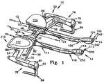
- FIG. 1is a perspective view of an exemplary embodiment of a handlebar with removable and adjustable aerobars according to the principles of the present invention
- FIG. 2is a perspective view of the handlebar of FIG. 1 with forearm rest members removed;
- FIG. 3is an exploded perspective view of the handlebar of FIG. 1 illustrating the components thereof, one forearm rest not shown for clarity;
- FIG. 3Ais a perspective view of a portion of the handlebar of FIG. 3 with one of the aerobar attachment mechanisms in section;
- FIG. 4is a front view of the handlebar of FIG. 1 ;
- FIG. 5is a bottom view of the handlebar of FIG. 1 ;
- FIG. 6is a sectional view of a lateral portion of the handlebar of FIG. 5 taken along line 6 - 6 thereof;
- FIG. 7is a top view of the handlebar of FIG. 1 ;
- FIG. 8is a sectional view of one of the aerobar clamping mechanisms of the handlebar of FIG. 7 taken along line 8 - 8 thereof;
- FIG. 9is a sectional view of the other of the aerobar clamping mechanisms of the handlebar of FIG. 7 taken along line 9 - 9 thereof;
- FIG. 10is an enlarged, sectional view of an exploded aerobar clamping mechanism of the present invention taken along line 10 - 10 of FIG. 3 a;
- FIG. 11is an enlarged, sectional view of an assembled aerobar clamping mechanism of the present invention.
- FIG. 12is perspective view of a first alternative embodiment, showing a clip-on aerobar version of the present invention.
- FIG. 13is an exploded view of a clip-on aerobar assembly of the clip-on aerobar of FIG. 12 ;
- FIG. 14is a sectional view of the clamping mechanism of the aerobar of the present invention taken along line 14 - 14 of FIG. 12 ;
- FIG. 15is an enlarged, sectional view of the clamping mechanism of the aerobar of the present invention.
- FIG. 16is a perspective view of a second alternative embodiment, showing a second clip-on aerobar version of the present invention.
- FIG. 17is a perspective view of the clip-on aerobar assemblies of the aerobar version of FIG. 16 with an aerobar clamping mechanism illustrated as exploded;
- FIG. 18is a side view of the clip-on aerobar version of FIG. 16 with the aerobar clamping mechanism shown in section;
- FIG. 19is an enlarged side view of the sectioned aerobar clamping mechanism of FIG. 18 .
- FIG. 20is an enlarged side sectional view of a first alternate embodiment “eccentric” collet useable with the handlebar of the present invention shown in FIG. 1 ;
- FIG. 21is an enlarged side sectional view of a second alternate embodiment “colinear” collet useable with the handlebar of the present invention shown in FIG. 1 ;
- FIG. 22is an enlarged side sectional view of the primary embodiment “bi-axial” collet shown in FIGS. 1-11 .
- a handlebar system 10 of the present inventionis shown in FIGS. 1-11 , that is capable of being attached to a bicycle, or other similar vehicle, of the type that requires a handlebar-like device either for use as a steering device, or otherwise, as a device for being gripped by a user for one purpose or another.
- the handlebar system 10includes two primary components, a handlebar 12 , and aerobars that are shown in the drawings as including a first aerobar 14 and a second aerobar 16 .
- FIG. 1As depicted in FIG. 1 , three axes are shown, including travel axis T, handlebar axis H, and vertical axis V. It should be understood that the names described to these particular axes are for purposes of reference for the instant description, and are not to be considered to be limitations.
- the vertical axismay not be disposed vertically if, for example, the handlebar could be positioned on a bicycle at a 90 degree angle to the angle of disposition suggested by FIG. 1 .
- the travel axis Twas so named, because it tends to indicate an axis that is generally parallel to the line along which a vehicle to which the handlebar system 10 is attached travels.
- Handlebar axis His so named because it comprises the major axis of the handlebar 12 , as it will be noted that the length of the handlebar along axis H is substantially greater than its length along either axis T or V.
- Axis Vis referred to as the vertical angle, as axis V would normally extend vertically of the handlebar system 10 is attached to a bicycle in orientation similar to that shown in FIG. 1 .
- axes T, H and Vare perpendicular to each other, and as such, could also be thought of as “X, Y, Z” axes, to help provide a better reference to coordinates, that relate to relative directions and positions of the various components of the handlebar system 10 .
- the handlebar system and its various componentsmay be made out of any one or a combination of a variety of materials.
- the handlebar system 10 with its various componentsare preferably primarily comprised of a fiber reinforced plastic material, such as carbon fiber-type material.
- a fiber reinforced plastic materialsuch as carbon fiber-type material.
- the Applicantshave found, after having produced such fiber reinforced plastic components for more than a decade, that such fiber reinforced plastic materials, when used in connection with bicycle components, provide bicycle components that are both very strong and very light weight. Strength and light weight are prized attributes of bicycle components in general, and especially bicycle components that are being used by competitors. In this regard, for example, many high-level competitors at events, such as the Iron Man Triathlon, and the Tour de France ride bicycles with several fiber reinforced plastic components, such as wheels, handlebars, hubs, cranks and the like.
- the handlebar 12 of the system 10includes a center section 30 that is sized and configured for being received by a clamp of a stem of a bicycle (both of which are not shown) or clamp of such other vehicles to which the handlebar system may be attached.
- the center 30is shown as being generally tube-like in configuration, and may possess any one of a variety of cross sectional shapes.
- the center section 30preferably has either a cylindrical, ovaloid or elliptical cross section, when such cross section is made in a plane that contains both the travel axis and vertical axis.
- a first laterally extending portion 34is disposed outboard of the center section 30
- a second laterally extending portion 36is disposed outboard of the center section 30 on an opposite side of the center section 30 .
- the first laterally extending portion 34includes a proximal end portion 48 disposed adjacent to the center section 30 , a distal end portion 50 , a leading edge portion 52 , and a trailing edge portion 54 .
- the first laterally extending portion 34also includes an upper surface 55 and a lower surface 56 (see e.g. FIG. 2 ).
- the second laterally extending portion 36includes a proximal portion 58 , a distal portion 60 , a leading edge portion 62 , a trailing edge portion 64 , and an upper surface 68 and a lower surface 70 (see e.g. FIG. 3 ).
- first and second laterally extending portions 34 , 36are generally winged-shaped, having smooth leading edges, upper and lower surfaces, and trailing edges.
- the winged-shaped configurationshelp to reduce air resistance as the handlebar moves through the air during the riding of a bicycle.
- wingscan be designed to impart lift (in the case of an airplane), down force (in the case of a race car), or to remain neutral. It has been found by Applicants that the wing configuration should preferably be designed to be neutral, providing neither down force nor lift.
- a first hand grip portion 74is disposed at the distal end portion 50 of the first laterally extending portion 34 of the handlebar, and a second hand grip portion 78 is disposed at the distal end portion 50 of the second laterally extending portion 36 .
- Each of the first and second hand grip portionsare designed to provide a suitable gripping surface for the user riding the bicycle, while being designed to do so in a configuration that helps to reduce aerodynamic drag, and promotes smooth air flow across the surfaces of the hand grip portion.
- Each of the first and second hand grip portions 74 , 78include a rounded first end 79 , 81 , respectively, each first end of which includes a slot 80 , 82 .
- the slots 80 , 82are provided for receiving hand brake levers 84 , 86 .
- the hand brake levers 84 , 86are pivotally connected to the first and second hand grip portions 74 , 78 , for permitting the user to actuate the brakes of the bicycle.
- the hand brake lever 84has a head that is received in the slot 80 of the first end 79 of the hand grip portion 74 and includes a bore 75 that is situated to coaxially align with bore 71 of the first end 79 .
- a grommet or the like 76may be provided in the bore 75 while a pivot pin 72 extends through the grommet and bores 71 , 75 . In this manner, the hand brake lever 84 pivots about the pivot pin 72 .
- the hand brake lever 86has a head that is received in the slot 82 of the first end 81 of the hand grip portion 78 and includes a bore 85 that is situated to coaxially align with bore 82 of the first end 81 .
- a grommet or the like 86may be provided in the bore 85 while a pivot pin 83 extends through the grommet and bores 82 , 85 . In this manner, the hand brake lever 86 pivots about the pivot pin 83 .
- the hand brake lever 84is connected to a brake cable 88 (see e.g. FIGS. 1 and 2 ) while hand brake lever 86 is connected to a brake cable 89 .
- the brake cables 88 and 89are connected to front and rear (or vice versa) brake actuators (not shown) of the vehicle (e.g. bicycle).
- the brake cable 88is coupled to hand brake lever 84 , and extends generally axially through the hand grip portion 74 , axially through the distal end portion 50 of the laterally extending portion 34 and emerges from a slot 92 on the underside 56 of the laterally extending portion 34 .
- brake cable 89is coupled to hand brake lever 86 and extends generally axially through the hand grip portion 78 , axially through the distal end portion 60 of the laterally extending portion 36 and emerges from a slot 93 on the underside 70 of the laterally extending portion 36 . Thereafter, both brake cables 88 , 89 are routed as known in the art.
- a first aerobar receiving clamp 90is also disposed on the laterally extending portion 34
- a second aerobar clamp 92is also disposed on the second laterally extending portion 36 .
- the aerobar receiving clamps 90 , 92generally have a primary axis PA (see e.g., FIGS. 1 and 10 ) that is generally parallel to the travel axis T, but may be offset from travel axis T, depending upon the pitch of the handlebar.
- the first aerobar clamp 90includes a front end 91 , and a rear end 93 .
- the second aerobar receiving clamp 92includes a front end 94 and a rear end 96 .
- the aerobar receiving clamps 90 , 92have generally hollow interiors, as will be described in more detail below, and are provided for clamping the aerobars 14 , 16 respectively onto the handlebar 12 .
- the first aerobar 14is generally hollow and tubular in nature, and may be comprised of either a metal material such as steel or aluminum, or alternately, a carbon fiber material.
- the preferred material from which the aerobar 14 is madeis carbon fiber, that, because of its strength and light weight, the Applicants have found to be especially advantageous, and desired by competitive riders such as racers and triatheletes. Those who are most cost and less performance conscious, may choose to use either light metal aerobars 14 , 16 (e.g. titanium, aluminum) or even bars made of steel.
- the first aerobar 14includes a first or proximal end 98 , a second or distal end 100 , an extension portion 102 , a handgrip portion 104 , and a bending transition portion 106 that is disposed between the extension portion 102 and the hand grip portion 104 .
- the second aerobarincludes a first or proximal end 110 , a second or distal end 112 , an extension portion 114 , a hand grip portion 116 and a bending transition portion 118 that is disposed between the extension portion 114 and hand grip portion 116 .
- the first ends 94 and 110 of the aerobarare sized and configured for being received within the aerobar clamp, as will be described in more detail below.
- the extension portions 102 , 114are generally linear, and extend forwardly, in a direction that may be co-linear with the travel axis T of the bicycle. However, as will be explained in more detail below, the extension portions need not be co-linear with travel axis T.
- extension portions 102 , 114are to provide for a forward placement of the hand grip portions 104 , 116 , so that when the rider is riding in a crouch position, the hand grip portions 104 , 116 will be placed in the proper position for the user.
- the hand grip portions 104 , 116are sized, configured and positioned to be gripped by the hands of the user.
- the hand grip portions 104 , 116are placed at an angle by the respective bending portions 106 , 118 to be ergonomically appropriate for the rider.
- a completely linear aerobarwould be uncomfortable for a rider due to the fact that 90 degrees is at or passed the limit of the range of motion of the wrist joint of the user.
- a plurality of collets of varying pitchwill be offered to customers.
- the colletscould be offset with a one degree offset, two degree offset, three degree offset, etc.
- the first 90 and second 92 aerobar receiving clamps 90 , 92preferably comprise first and second collet receivers 124 , 125 .
- the first and second collet receivers 124 , 125preferably comprise, interior, axially extending first and second receiving sleeves 124 , 125 respectively, for receiving a collet, such as first and second collets 160 , 162 , respectively, that themselves include interior passageways for receiving the aerobars 102 , 114 .
- receiving sleeves 124 , 125are generally identical for both aerobar clamps 90 , 92 , only the receiving sleeve 124 of the aerobar clamp 90 will be described, particularly with respect to FIG. 10 , it being understood that receiving sleeve of aerobar clamp 92 is virtually identical.
- the receiving sleeve 124includes a proximal end 126 and an open distal end 128 .
- the proximal end 126includes a beveled radially extending end surface 130 .
- a tapered axially extending surface 132extends from the beveled end surface 130 to the distal end 128 of the receiving sleeve 124 .
- the axially extending surfaceis tapered such that it is narrower, close to the proximal end 126 and wider, close to the distal end 128 , such that diameter A, adjacent to the closed proximal end is smaller than diameter B, that is adjacent to the open distal end 128 .
- the tapered axially extending surface 132defines a frusto-conical interior passageway 134 as described above.
- the frusto-conical interior passageway 134includes an axis E.
- An axially extending passageway 138extends from the base surface 130 in a generally proximal direction.
- a retaining screw 150 having a head 140 and shaft 142is sized to be received by the passageway 138 .
- the shaft 142includes exterior threads 146 that are received in internal threaded passageway 161 of the collet 160 .
- the collet 160is retained in the receiving sleeve 124 , and the retaining screw 150 can serve as an axial mover of the collet, as rotation of the screw 150 in the threaded passageway (see FIG. 11 ) moves the collet 160 in an axial direction as indicated by arrow E of FIG. 10 .
- the retaining screw 150further includes a passageway 144 for allowing a gear cable to extend therethrough.
- the first collet 160is provided for being received within the receiving sleeve 124 of the aerobar clamp 90 and a second collet 162 is designed for being received within the receiving sleeve 125 of the aerobar clamp 92 .
- Each colletincludes an end 167 having a central aperture 168 .
- Central aperture 168opens into the threaded central screw-receiving passageway 161 , and extends through a frusto-conical base portion 169 .
- the threaded passageway 161is sized and configured to receive the threads of the screw 150 .
- the colletseach include a frusto-conical outer surface 174 that includes a plurality of spaced axially extending slots (here shown as four slots) 176 , for dividing the shaft receiving portion 172 of the collet into a plurality of segments.
- the axially extending slots 176thereby define segments that permit the diameter of the shaft receiving portion 172 of the collets 160 , 162 to be expanded.
- the exterior diameter of an aerobarmay be slightly larger than the interior diameter of a collet.
- the segment 174may “flower pedal” outwardly a little bit to thereby increase the effective diameter of the collet. This ability of the segment to allow such radial expansion makes it easier to insert the aerobar within the cylindrical inner space that is defined by the cylindrical inner wall of the collets.
- the radial pressure exerted by the interior wall 132 on the exterior surface wall 174 of the colletreduces the radial diameter of the interior passageway 157 , thereby causing the collet 160 , 162 to be radially compressed, to thereby exert a compressive, gripping force against the exterior surface of the aerobar inserted therein.
- this dual compression, and thereby the pressure exerted against the aerobarwill increase as the collet increasingly moves in a proximal direction within the interior 134 of receiving sleeve 124 .
- This proximal directionis indicated by arrow F in FIG. 10 .
- the exterior wall 174 of the colletis somewhat frusto-conical in nature, or at least has an effectively frusto-conical shape due to the increased diameter of the enlarged diameter end portion 164
- the interior passageway 157 and interior wall 165 of the colletis cylindrical in configuration for receiving the generally cylindrical surface of the aerobar.
- a “cylindrical” configurationis not that important, it is important to note that the interior wall 165 ( FIG. 22 ) should have a constant diameter and constant cross section shape throughout its length, or to such point as where the constant diameter portion joins with the base portion.
- the axis 0 of the overall colletis offset from an axis S of the cylindrical passageway 157 of the sleeve into which the aerobar fits.
- the distal end portion 179 of the collet 160is shown.
- the thickness of the end wall at the distal endvaries about the circumference. For example, at the point equivalent to 12:00 ( 1200 in FIG. 22 ), the wall is somewhat thinner. At the 3:00 ( 300 in FIG. 22 ) and 9:00 ( 900 in FIG. 22 ) positions, the wall 184 is thicker. The wall reaches its thickest at 6:00 ( 600 in FIG.
- FIG. 22which is disposed 180 degrees from 12:00. This thickness in the wall reflects the offset between the axis of the overall collet 162 , the axis of the cylindrical passageway 168 . The reader's attention is also directed to FIG. 22 , where it is shown that at the thickness of the collet 160 at the 6:00 position 600 varies linerarly between the proximal and distal ends of the collet 160 .
- the angular offset between the two axes S, Oshould be somewhere between about 0.1 and 5 degrees, and preferably somewhere about 1.0 and 3 degrees. This axial offset will cause an aerobar that is inserted within the collet 160 to be positioned along an axis S that is co-linear with the interior passageway 157 of the collet, rather than being positioned at axis O, which is the axis of the entire collet 160 , and which, is co-linear with the axis of the receiving sleeve.
- the axial offset between the axis S of the interior passageway 157 and interior wall 165 of the collet 160 , and hence the axis of the aerobar 14 , 16 ; and the axis 0 of the overall collet 162 and the receiving sleeve 92 axis,causes the aerobars to extend from the receiving sleeve along the axis S of the interior of the collet.
- the rotational position of the colletscan be varied by the user.
- the rotational position of the colletthe user can effect different axial orientations of the aerobars 14 , 16 .
- the axis of the aerobarscan also be varied, at least 360 degrees.
- FIGS. 7 through 9are sectional views taken along lines 8 - 8 and 9 - 9 respectively of FIG. 7 .
- FIG. 8it will be noted by the thickened portion of collet 160 is disposed at approximately a 9:00 position. By so doing, this causes the aerobar 14 to be oriented inwardly.
- collet 162FIG. 9
- the thickened portion of the collet 160is located at the 6:00 position 600 .
- the handlebarincludes a collet receiver for disposing the collet along a first axis, and wherein the collet is capable of receiving an aerobar such that the aerobar is disposed along a second axis offset from the first axis.
- a first forearm rest member 200can be attached to the handlebar 12 through a pair of screws 202 that extend through the first forearm rest member 200 and received within threaded blind apertures that are disposed on a raised armrest surface 204 .
- the armrest surface 204is disposed on the upper surface of the laterally extending portion 34 .
- a pad 220(see FIG. 1 ) is preferably disposed on the forearm rest member 200 .
- a second forearm rest member 219can also be attached to the handlebar 12 through a pair of screws 212 that extend through the second forearm rest member and received with threaded blind apertures that are disposed on a raised armrest surface 214 .
- the armrest surface 214is disposed on the upper surface of the laterally extending portion 36 .
- a pad 222(see FIG. 1 ) is preferably disposed on the forearm rest member.
- a gear shift lever 240is shown disposed on the end 100 of aerobar 14
- a gear shift lever 250is shown disposed on end 112 of aerobar 16
- a gear shift cable 242is operatively coupled to the gearshift lever 240 and extends through the aerobar 14 and out of the rear of the aerobar receiving clamp 90 (through screw 150 ).
- the gear shift cable 252is operatively coupled to the gearshift lever 250 and extends through the aerobar 16 and out of the rear of the aerobar receiving clamp 92 .
- one gear shift lever 240controls the operation of the rear-wheel mounted cassette, (not shown) whereas the other gear shift lever 250 controls the movement of the chain among the sprockets of the crankset (not shown).
- cassettes and cranksetsare well known in the art, and available from a variety of companies, such as Shimano, Sram & Campagnolo
- FIGS. 20 and 21Alternate embodiment collets 601 , 700 are shown in FIGS. 20 and 21 , with FIG. 20 showing an eccentric collet 601 , and FIG. 21 showing a co-linear collet 700 .
- Eccentric collet 601is generally similar to collets 160 , 162 , and differs primarily in respect to the orientation of the axis of the inner surface 608 relative to the axis of the outer surface 606 .
- Excentric collet 601includes a proximal end 602 , that, in practice is located closer to the rear of the bicycle, and a distal end 604 that, in practice, is closer to the forward end of the bicycle.
- the colletincludes a cylindrical outer surface 606 , that is sized and configured for being received within the tapered receiving sleeve of the handlebar, and a cylindrical inner surface 608 , that is sized, configured and received for receiving the proximal end of an aerobar.
- a cylindrical outer surface 606that is sized and configured for being received within the tapered receiving sleeve of the handlebar
- a cylindrical inner surface 608that is sized, configured and received for receiving the proximal end of an aerobar.
- the portion of the collet wall 614 disposed at the 6:00 portion of the colletis significantly thicker than the portion of the collet wall 618 , disposed at the 12:00 portion 1200 of the collet. It will also be noticed that the 6:00 portion 614 has a uniform thickness along its entire length, from the proximal to distal ends.
- collet 601This configuration results in the overall axis of the collet EO being generally parallel to the axis ES of the inner wall 608 of the collet 601 .
- the axis of an aerobar that is inserted into the distal end 604 of collet 601will have an axis that is generally parallel to the overall axis EO of the collet.
- the axis ES of the aerobarwill be parallel to, but offset from the axis EO of the overall collet 601 .
- collet 601can be rotated about axis EO within the receiving sleeve of the handlebar.
- collet 601Because of the eccentric nature of collet 601 , the rotation of collet 601 within the handlebar will cause the axis of the aerobar to scribe a circle, during rotation, that has its center point at the overall axis EO of the collet, and a radius equal to the distance between axes EO and ES.
- FIG. 21A second embodiment collet 700 is shown in FIG. 21 .
- Collet 700is similar to collets 160 and 602 , insofar as collet 700 includes a proximal end 702 , a distal end 704 , an outer surface 706 , and an inner surface 708 .
- inner surface 708defines a sleeve for receiving the proximal end of an aerobar; and a series of parallel, blind slots 710 are provided for enabling the user to vary the radial diameter of the collet 700 , in a manner similar to that described above in connection with collet 160 .
- co-linear collet 700the 6:00 portion 714 and 12:00 portion 706 have generally the same thickness throughout their entire length. Additionally, it will be noted that the interior surface 708 , and exterior surface 706 are co-axial, such that both share a common axis CO, CS.
- collet 700does not have the adjustable angular and radial positionability features of collets 162 , 601 respectively.
- collet 700can be made to have much thinner walls, and a reduced diameter when compared to either collets 162 or 601 . This permits the manufacturer, to make collet 700 to have a smaller diameter and thereby, if the manufacturer so desires, reduce the jet-engine shaped “bulge” in the wing-shaped handlebar caused by the collet receiving portion of the handlebar.
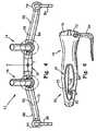
- FIGS. 12-15A second embodiment of an aerobar clamp system is depicted in FIGS. 12-15 .
- FIGS. 12-15shows a pair of aerobar clamp systems or assemblies 300 , 302 , for clamping aerobars 303 , 305 onto a more traditional handlebar, such as rams horn-like drop handlebars 304 .
- the aerobar clamp systemmay be considered a clip-on aerobar clamp system.
- the two aerobar clamp systems 300 , 302are generally identical. As such, only clamp 300 will be described herein below, it being understood that clamp 302 is identical thereto.
- Clamp system 300includes a clamp 308 that is comprised of a first clamping member 310 , that itself includes a frusto-spherical first clamp or clamp half 312 and an integral collet 314 .
- a generally cylindrical collet 315is also part of the clamp system 300 .
- Another part of the clamp 308is the frusto-spherical second clamp or clamp half 316 , that can be coupled to the first clamp half 312 of the first clamping member 310 .
- the first clamp half 312includes a first axially extending threaded aperture 322 , and a second axially extending threaded aperture 324 .
- the longitudinal extent of the apertures 322 , 324is along a line that is generally co-linear with axis J.
- line Jis also co-linear to the axis of the collet member 314 and the collar 315 along with being co-axial with the axis of the extension portion 382 of the aerobar 303 .
- the first clamp half 312also includes a radially extending first mating face 326 , and a second radially extending mating face 328 .
- a hemi-cylindrical handlebar receiving surface 330is generally concave in nature, and is designed for snugly receiving a handlebar (e.g. handlebar 304 as illustrated in FIG. 12 ) so that the aerobar clamps 300 , 302 can be fixedly, but removably coupled to the handlebar 304 .
- the particular embodiment of a first clamp half 312 of the present inventionis also shown to include a pair of planar side surfaces, 332 .
- the second clamp half 316includes a frusto-spherical outer surface 340 , having a first aperture 342 , that is counter sunk into a recess 343 .
- a second, like aperture 344is also provided that is disposed on another side of the second clamp half 316 .
- the first and second aperture 342 , 344 of the second clamp half 316are sized, configured and positioned to be aligned with the first and second apertures 322 , 324 of the first clamp member 310 , so that when the clamp members are placed together, such as is shown in FIGS.
- a first joinder screw 354can extend through the first aperture 342 , 322 ; and a second joinder screw 356 can extend through the second joinder apertures 344 , 324 .
- the first and second clamp halves 310 , 316can be joined together to snugly engage the handlebar 304 , such as shown in FIG. 12 , to fixedly position the clamp 308 and thus the clamp system 300 onto the handlebar 304 .
- the second clamp half 316also includes a first and second mating faces 346 , 348 that are sized, positioned and configured to mate with mating faces 326 , 328 respectively, a hemi-cylindrical handlebar receiving surface 350 , and a pair of planar side surfaces 352 .
- the planar side surfacesshould be designed to mate with the planar side surfaces 332 of the first clamp half, to form a pleasing aesthetic device.
- the integral collet 314includes a first proximal end 357 , a second or distal end 358 , and a smooth, generally cylindrical interior surface that is sized and configured for receiving the proximal end 380 of the aerobar 303 therein.
- the collet 314also includes a threaded outer surface 361 , and a plurality of spaced, axially extending slots 362 , with each slot 362 having an open end 364 adjacent to the distal end 358 of the collet 314 . While not necessarily so, the integral collet 314 preferably operates similarly to the collets 160 , 162 shown in connection with the first embodiment, and can be configured similarly to any of collets 160 , 601 , or 700 .
- the generally cylindrical collar 315is sized and configured to interiorly receive the collet 314 .
- the collar 315includes a generally cylindrical, threaded inner surface 372 that defines an axially extending passageway 373 for receiving the exterior surface of the collet 314 .
- the threads 361 of the colletengage the interior threads 372 of the collar 315 , to enable the collar 315 to move axially proximally on the collar 314 through rotation.
- the collar 315also includes a proximal end 376 and a distal end 378 .
- the two collar halves 310 , 316are fitted around a handlebar 304 at an appropriate position.
- a joinder screwis then inserted through the appropriate aperture 342 , 326 ; and 322 , 324 , to join the two clamp halves to snugly grab and engage the handlebar 304 .
- the proximal end 380 of the extension portion 382 of aerobar 303is then inserted into the interior passageway of the collet 314 .
- the aerobar 303is rotated about the axis of the extension 382 to orient the hand grip portion 384 in a proper orientation.
- the collar 315Prior to the aerobar being inserted into the interior of the collet 314 , the collar 315 is slipped over the proximal end 380 of the aerobar and pushed axially outwardly out of the way, to not impede the insertion of the proximal end 380 of the aerobar 303 into the interior passageway of the collet.
- the collar 315is then moved axially along the extension portion 382 of the aerobar toward the collet 314 and the collar 315 is then rotated upon engagement with the collet 314 .
- Rotation of collar 315causes the interior threads 372 of the collar to engage the exterior threads 361 of the collet 314 .
- the collarmoves axially and proximally on the collet 314 in a direction toward the clamp halves 310 , 316 .
- the usercan vary the axial position of the aerobar 303 to a position wherein it is most comfortable to her.
- the usercan orient the handgrip portion 384 in a position that is comfortable to her.
- the collaris then engaged to the collet, so that when fully and securely engaged, the axial and rotational position of the aerobar that the user desires is maintained during use.
- FIG. 16shows a pair of aerobar clamp systems or assemblies 400 , 402 , mounted onto handlebars 404 for attaching aerobars 403 , 405 to the handlebar 404 .
- Forearm rest assemblies 410 , 412may be provided and mounted to respective aerobar clamp systems 400 , 402 .
- the two aerobar clamp systems 400 , 402are generally identical. As such, features discussed with respect to one aerobar clamp system are applicable to the other aerobar clamp system.
- the two forearm rest assemblies 410 and 412are generally identical. As such, features discussed with respect to one forearm rest assembly are applicable to the other forearm rest assembly.
- aerobar clamp system 400includes an attachment member 420 that is comprised of a generally tubular body 422 .
- the tubular body 422is adapted to be received and attached onto the handlebar 404 .
- a proximate end 424 of the tubular body 422includes a curved notch 426 configured essentially complementarily to the outside surface of the handlebar 404 .
- a bracket 428is mounted around the handlebar 404 and into screw reception bores in the body 422 .
- the body 422may be positioned in various angular orientations perpendicular about a longitudinal axis of the handlebar portion 407 to which the aerobar clamp system 400 is mounted, for allowing the aerobar 405 to be positioned in various angular orientations.
- the body 422defines an integral collet 432 of a generally tubular shape that is sized and configured for receiving the proximal end 444 of the aerobar 403 therein.
- the collet 432includes a plurality of spaced, axially extending slots 434 , with each slot 434 having an open end adjacent to the distal end of the collet 432 .
- the collet 432also includes a threaded outer surface 436 for threaded engagement with internal threads of a collar 440 of the aerobar clamp system 400 . While not necessarily so, the integral collet 432 preferably operates similarly to the collets shown and described in connection with the previous embodiments.
- the collar 440has an opening 441 that is sized and configured to receive the proximate end 444 of the aerobar 403 and an internal, axially extending tubular passageway that is sized and configured to be received over the collet 432 and onto the threaded portion 436 .
- the interior threads of the collar 440cooperate with the outer threads 436 of the collet 432 to enable the collar 440 to move axially and proximally on the collet 432 through rotation.
- the collar 315also includes a proximal end 376 and a distal end 378 .
- the proximal end 444 of the aerobar 403is then inserted into the interior passageway of the collet 432 of the attachment member 420 .
- the aerobar 403is rotated about the axis of the extension collet 432 to orient the hand grip portion 445 of the aerobar 403 in a proper orientation.
- the collar 440Prior to the aerobar being inserted into the interior of the collet 432 , the collar 440 is slipped over the proximal end 440 of the aerobar 403 and pushed axially outwardly out of the way, to not impede the insertion of the proximal end 444 of the aerobar 403 into the interior passageway 443 of the collet 432 .
- the collar 440is then moved axially toward the collet 432 .
- the collar 440is then rotated upon engagement with the collet threads 436 .
- Rotation of collar 440causes the interior threads of the collar to engage the exterior threads 436 of the collet 432 .
- the collarmoves axially and proximally on the collet 432 .
- the usercan vary the axial position of the aerobar 403 to a position wherein it is most comfortable to him.
- the usercan orient the handgrip portion 445 in a position that is comfortable to him.
- the collaris then engaged to the collet, so that when fully and securely engaged, the axial and rotational position of the aerobar that the user desires is maintained during use.
- the forearm rest assembly 410includes a mounting plate 500 that is adapted for attachment to the attachment member 420 .
- the mounting plate 500is attached to an armrest reception area 430 of the body 422 of the attachment member 420 .
- the armrest reception area 430includes four screw reception bores two of which are configured to receive mounting screws 501 for attaching the mounting plate 500 to the mounting plate 500 .
- a contoured armrest 504is situated onto and over the mounting plate 500 and attached to the mounting plate 500 via mounting screws 505 .
- An armrest pad or cushion(not shown) is preferably, but not necessarily, provided on the contoured armrest 504 .
- the contoured armrest 504may be adjustable relative to the attachment member 420 .
- the aerobar clamp system 402includes an attachment member 508 that is identical to the attachment member 420 of clamp system 400 and a collar 510 that is identical to the collar 440 of the clamp system 400 .
- the aerobar clamp system 402is thus adapted in like manner to the aerobar clamp system 402 , to adjustably retain an aerobar ( 405 ) relative to the handlebar 404 .
- An armrest assembly 412is preferably but not necessarily, associated with the aerobar clamp system 402 .
- the clamp system 402includes the attachment member 508 that is comprised of a generally tubular body 520 .
- the tubular body 520is adapted to be received and attached onto the handlebar 404 such as handlebar portion 407 .
- a proximate end 522 of the tubular body 520includes a curved notch 524 configured essentially complementarily to the outside surface of the handlebar portion 407 .
- a bracket 526is mounted around the handlebar portion 407 and into screw reception bores in the body 520 .
- the body 520may be positioned in various angular orientations perpendicular to a longitudinal axis of the handlebar portion 407 to which the aerobar clamp system 400 is mounted. This allows for the aerobar 405 to assume various angular orientations about the handlebar portion 407 .
- the body 520defines an integral collet 530 of a generally tubular shape that is sized and configured for receiving the proximal end 541 of the aerobar 405 therein.
- the collet 530includes a plurality of spaced, axially extending slots 532 , with each slot 532 having an open end adjacent to the distal end of the collet 530 .
- the collet 530also includes a threaded outer surface 534 for threaded engagement with internal threads 536 of the collar 510 of the aerobar clamp system 402 . While not necessarily so, the integral collet 530 preferably operates similarly to the collets shown and described in connection with the previous embodiments.
- the collar 510has an opening that is sized and configured to receive the proximate end 541 of the aerobar 405 and an internal, axially extending tubular passageway that is sized and configured to be received over the collet 530 and onto the threaded portion 534 .
- the interior threads 536 of the collar 510cooperate with the outer threads 534 of the collet 510 to enable the collar 510 to move axially and proximally on the collet 530 through rotation.
- the proximal end 541 of the aerobar 405is then inserted into the interior passageway 531 of the collet 530 of the attachment member 508 .
- the aerobar 405is rotated about the axis of the extension collet 530 to orient the hand grip portion 546 (see FIG. 18 ) of the aerobar 405 in a proper orientation.
- the collar 510Prior to the aerobar being inserted into the interior of the collet 530 , the collar 510 is slipped over the proximal end of the aerobar 405 and pushed axially outwardly out of the way, to not impede the insertion of the proximal end 541 of the aerobar 405 into the interior passageway 541 of the collet 530 .
- the collar 510is then moved axially toward the collet 530 .
- the collar 510is then rotated upon engagement with the collet threads 536 .
- Rotation of collar 510causes the interior threads 534 of the collar 510 to engage the exterior threads 536 of the collet 530 .
- the collarmoves axially and proximally on the collet.
- the usercan vary the axial position of the aerobar 405 to a position wherein it is most comfortable to him.
- the usercan orient the handgrip portion 546 of the aerobar 405 in a position that is comfortable to him.
- the collaris then engaged to the collet, so that when fully and securely engaged, the axial and rotational position of the aerobar that the user desires is maintained during use.
- the forearm rest assembly 412includes a mounting plate 512 that is adapted for attachment to the attachment member 508 .
- the mounting plate 512is attached to an armrest reception area 528 of the body 520 of the attachment member 508 .
- the armrest reception area 528includes screw reception bores two of which are configured to receive mounting screws 544 for attaching the mounting plate 512 to the mounting area 528 .
- a contoured armrest 514is situated onto and over the mounting plate 512 and attached to the mounting plate 512 via mounting screws.
- An armrest pad or cushion(not shown) is preferably, but not necessarily, provided on the contoured armrest 514 .
- the contoured armrest 514may be adjustable relative to the attachment member 508 .
Landscapes
- Engineering & Computer Science (AREA)
- Mechanical Engineering (AREA)
- Steering Devices For Bicycles And Motorcycles (AREA)
Abstract
Description
Claims (23)
Priority Applications (6)
| Application Number | Priority Date | Filing Date | Title |
|---|---|---|---|
| US11/259,500US7698967B2 (en) | 2004-10-29 | 2005-10-26 | Bicycle handlebar with removable and adjustable aerobar |
| CA2584994ACA2584994C (en) | 2004-10-29 | 2005-10-27 | Bicycle handlebar with removable and adjustable aerobar |
| EP05825052.3AEP1819580B1 (en) | 2004-10-29 | 2005-10-27 | Bicycle handlebar with removable and adjustable aerobar |
| JP2007539115AJP2008518826A (en) | 2004-10-29 | 2005-10-27 | Bicycle handlebar with removable and adjustable aero bar |
| AU2005302582AAU2005302582B2 (en) | 2004-10-29 | 2005-10-27 | Bicycle handlebar with removable and adjustable aerobar |
| PCT/US2005/038779WO2006050030A2 (en) | 2004-10-29 | 2005-10-27 | Bicycle handlebar with removable and adjustable aerobar |
Applications Claiming Priority (2)
| Application Number | Priority Date | Filing Date | Title |
|---|---|---|---|
| US62316304P | 2004-10-29 | 2004-10-29 | |
| US11/259,500US7698967B2 (en) | 2004-10-29 | 2005-10-26 | Bicycle handlebar with removable and adjustable aerobar |
Publications (2)
| Publication Number | Publication Date |
|---|---|
| US20060090589A1 US20060090589A1 (en) | 2006-05-04 |
| US7698967B2true US7698967B2 (en) | 2010-04-20 |
Family
ID=36260299
Family Applications (1)
| Application Number | Title | Priority Date | Filing Date |
|---|---|---|---|
| US11/259,500Expired - Fee RelatedUS7698967B2 (en) | 2004-10-29 | 2005-10-26 | Bicycle handlebar with removable and adjustable aerobar |
Country Status (6)
| Country | Link |
|---|---|
| US (1) | US7698967B2 (en) |
| EP (1) | EP1819580B1 (en) |
| JP (1) | JP2008518826A (en) |
| AU (1) | AU2005302582B2 (en) |
| CA (1) | CA2584994C (en) |
| WO (1) | WO2006050030A2 (en) |
Cited By (30)
| Publication number | Priority date | Publication date | Assignee | Title |
|---|---|---|---|---|
| US20070221008A1 (en)* | 2006-03-23 | 2007-09-27 | Sram Corporation | Bicycle Shifter |
| US20080053266A1 (en)* | 2006-08-30 | 2008-03-06 | Canyon Bicycles Gmbh | Bicycle handlebar |
| US20080110291A1 (en)* | 2006-11-13 | 2008-05-15 | Vitek Christopher J | Ventilated bicycle handlebars, handlebar grips and gloves |
| US20100059638A1 (en)* | 2008-09-11 | 2010-03-11 | Keiji Taiga | Accessory connection device for bicycles |
| US20100199801A1 (en)* | 2009-02-12 | 2010-08-12 | Giant Manufacturing Co., Ltd. | Aerodynamically configured handlebar assembly for a bicycle |
| US20100213684A1 (en)* | 2009-02-25 | 2010-08-26 | Specialized Bicycle Components, Inc. | Handlebar stem for a bicycle |
| US20110100154A1 (en)* | 2009-11-05 | 2011-05-05 | Johnson Paul D | Ergonomic bicycle hand rest |
| US8172247B2 (en) | 2010-07-02 | 2012-05-08 | Trek Bicycle Corporation | Bicycle aero handlebar assembly |
| US20120167706A1 (en)* | 2010-12-03 | 2012-07-05 | Campagnolo S.R.L. | Control lever and actuation device of a bicycle gearshift of the bar-end type |
| USD668191S1 (en)* | 2011-04-01 | 2012-10-02 | Velo Enterprise Co., Ltd. | Handlebar end for a bicycle |
| US8307736B2 (en)* | 2011-03-22 | 2012-11-13 | Chang Hui Lin | Adjustable bicycle handlebar |
| US20150068351A1 (en)* | 2010-04-29 | 2015-03-12 | Claude Nadeau | Control Bar for Traction Mechanisms |
| USD725558S1 (en)* | 2012-12-07 | 2015-03-31 | Jochen Klieber | Bicycle part |
| WO2015130775A1 (en)* | 2014-02-25 | 2015-09-03 | Domesick Michael H | Plank support exercise apparatus and related methods |
| US20150298761A1 (en)* | 2014-04-17 | 2015-10-22 | Thomas S. Felker | Dual powered propulsion system |
| US20160176468A1 (en)* | 2014-12-23 | 2016-06-23 | Aerocat LLC | Streamlined aerobar for bicycle |
| US9415825B1 (en)* | 2015-03-31 | 2016-08-16 | Nicholas M Salazar | Combination bicycle handlebar and stem assembly |
| US20170008598A1 (en)* | 2015-07-06 | 2017-01-12 | Bernard E. Brown | Bicycle handlebar assembly with forearm support |
| US20180064981A1 (en)* | 2015-02-25 | 2018-03-08 | Michael Harris Domesick | Plank Support Exercise Apparatus and Related Methods |
| US9994812B2 (en) | 2012-04-04 | 2018-06-12 | University Of Washington Through Its Center For Commercialization | Systems and method for engineering muscle tissue |
| US9994280B1 (en)* | 2017-04-12 | 2018-06-12 | Tien Hsin Industries Co., Ltd. | Auxiliary control device for bicycle |
| US20190077484A1 (en)* | 2015-05-21 | 2019-03-14 | Trek Bicycle Corporation | Rigid frame with high-compliance seat tube and internal cable routing |
| US20190359280A1 (en)* | 2016-09-26 | 2019-11-28 | Vroomen-White Design Inc. | Adjustable aerobar riser assembly for a bicycle |
| US10569827B2 (en) | 2014-04-17 | 2020-02-25 | Thomas S. Felker | Bicycle dual power turning track, rack, pinion, and one-way bearing propulsion system |
| US10604250B2 (en) | 2016-10-05 | 2020-03-31 | Burton James Fenison | Hang glider control device |
| US20200102046A1 (en)* | 2018-04-12 | 2020-04-02 | Look Cycle International | Aerodynamic Assembly For Bike Handlebars |
| US10808741B2 (en) | 2013-03-15 | 2020-10-20 | Redshift Sports, LLC | Quick-release clamp with secondary retention mechanism |
| US11013955B2 (en) | 2016-04-15 | 2021-05-25 | Thomas S. Felker | Tri-power exercising device |
| US11608136B1 (en)* | 2021-11-30 | 2023-03-21 | Sienna Group Corp. | Bicycle armrest handlebar |
| US12268931B2 (en) | 2016-04-15 | 2025-04-08 | Thomas S. Felker | Exercise system |
Families Citing this family (20)
| Publication number | Priority date | Publication date | Assignee | Title |
|---|---|---|---|---|
| US7243572B1 (en)* | 2002-12-03 | 2007-07-17 | Deka Products Limited Partnership | Transporter shaft coupling and uncoupling |
| CN2895224Y (en)* | 2006-01-10 | 2007-05-02 | 展荧实业股份有限公司 | Improved structure of bicycle auxiliary handle fixing seat |
| US20090188344A1 (en)* | 2007-06-14 | 2009-07-30 | Timothy Tamcsin | Handlebar |
| US20090056495A1 (en)* | 2007-08-27 | 2009-03-05 | Todd Bischoff | Bicycle handlebar assembly |
| EP2030805B1 (en)* | 2007-08-29 | 2013-02-13 | Compositech, Inc. | Reinforced composite rim |
| TWI358371B (en)* | 2007-08-30 | 2012-02-21 | Compositech Inc | Aerobar assembly |
| GB0805190D0 (en)* | 2008-03-20 | 2008-04-30 | United Kingdom Sports Council | A means to redce aerodynamic drag of a bicycle and cyclist system |
| US20100326232A1 (en)* | 2009-06-24 | 2010-12-30 | Ming-Jen Wang | Supplemental set of handlebars for bicycle |
| US20120079910A1 (en)* | 2010-09-30 | 2012-04-05 | Wehage Kristopher T | Handlebar/stem attachment interface with minimal frontal area |
| US9067637B2 (en)* | 2011-04-28 | 2015-06-30 | John Irven Tolhurst | Adjustable folding handlebar for human powered vehicles |
| TWM431093U (en)* | 2012-01-18 | 2012-06-11 | Kwang Yang Motor Co | Carrying device for vehicle |
| US20150145230A1 (en)* | 2013-11-26 | 2015-05-28 | BikeStreet USA | Bicycle brake system |
| WO2017015181A1 (en)* | 2015-07-20 | 2017-01-26 | Cederstrom Jeff | Areobar-mounted rotational torque surge brake for a bicycle |
| DE202015008698U1 (en)* | 2015-12-18 | 2017-03-21 | Canyon Bicycles Gmbh | bicycle handlebars |
| JP6655842B2 (en)* | 2016-03-17 | 2020-02-26 | 圭 森田 | Fittings and handles for time trial bike handles |
| AU2017249427B2 (en)* | 2016-04-15 | 2020-04-09 | Thomas S. Felker | Bicycle dual power turning track, rack, pinion, and one-way bearing propulsion system |
| WO2018221223A1 (en)* | 2017-05-30 | 2018-12-06 | ヤマハ発動機株式会社 | Separated handlebars |
| US10807675B2 (en) | 2018-06-15 | 2020-10-20 | Sram, Llc | Integrated bicycle control device |
| US10513311B1 (en)* | 2018-06-15 | 2019-12-24 | Sram, Llc | Integrated bicycle control device |
| USD1075601S1 (en)* | 2023-12-28 | 2025-05-20 | Dongguan Feima Sporting Goods Co., Ltd. | Bicycle handlebar |
Citations (92)
| Publication number | Priority date | Publication date | Assignee | Title |
|---|---|---|---|---|
| DE278827C (en) | ||||
| US511479A (en)* | 1893-12-26 | Bicycle | ||
| US575936A (en) | 1897-01-26 | Manuel a | ||
| DE101297C (en) | 1898-04-01 | 1899-02-10 | Otto Ruhl | BICYCLE BRAKE ACTIVATES AUTOMATICALLY AT A CERTAIN TRAVEL SPEED |
| US1595557A (en) | 1926-03-09 | 1926-08-10 | Mamiya Fusajiro | Folding bicycle handle |
| FR638790A (en) | 1926-08-04 | 1928-06-02 | Velocipede with dual-pair steering and weather protection for the rider | |
| USD263293S (en) | 1979-06-18 | 1982-03-09 | Janson Paul M | Auxiliary bar for attachment to a bicycle handle bar |
| US4445396A (en) | 1980-03-06 | 1984-05-01 | Shimano Industrial Company Limited | Handlebar for a bicycle |
| US4462267A (en) | 1980-03-01 | 1984-07-31 | Shimano Industrial Company, Limited | Handlebar for a bicycle |
| USD289630S (en) | 1984-09-04 | 1987-05-05 | Owens Neil D | Auxiliary bicycle handlebar attachment |
| US4750754A (en) | 1987-01-09 | 1988-06-14 | Lennon Dan C | Bicycle and handlebar system |
| USD301027S (en) | 1985-09-26 | 1989-05-09 | 3T S.P.A. | Handlebar, especially for racing bicycle |
| US4829847A (en) | 1985-11-15 | 1989-05-16 | Modolo Adamo & C. S.N.C. | Bicycle handlebar, particularly for a racing bicycle |
| US4862762A (en) | 1987-03-30 | 1989-09-05 | Ross John T | Touring handle bar and brake adaptor lever |
| US4873886A (en) | 1988-01-26 | 1989-10-17 | Rolf Renner | Armrest for bicycle handlebar |
| US4878397A (en) | 1987-01-09 | 1989-11-07 | Lennon Dan C | Bicycle, handlebar and adapter system |
| US4903542A (en) | 1988-01-07 | 1990-02-27 | 3T S.P.A. | Bicycle handlebar assembly, particularly for sports bicycles |
| US4930798A (en) | 1987-11-13 | 1990-06-05 | Maeda Industries, Ltd. | Bicycle handle assembly |
| US4951525A (en) | 1988-12-13 | 1990-08-28 | 3T S.P.A. | Handlebars for cycles, particularly bicycles for triathlons and speed trials |
| USD315328S (en) | 1989-06-29 | 1991-03-12 | Profile For Speed, Inc. | Combined auxiliary bar and armrests for attachment to a bicycle handlebar |
| US5000469A (en) | 1989-06-09 | 1991-03-19 | Smith Cedric J | Bicycle handlebar arm rests |
| US5024119A (en) | 1986-05-28 | 1991-06-18 | Linden Paul R | Bicycle handlebars |
| US5033325A (en) | 1990-06-15 | 1991-07-23 | Profile For Speed, Inc. | Adjustable connection for bicycle handlebar |
| US5064157A (en) | 1990-05-01 | 1991-11-12 | Jim O'neal Distributing, Inc. | Mounting bracket for handlebar crossbar |
| US5083476A (en) | 1989-11-30 | 1992-01-28 | 3 T S.P.A. | Handlebar for cycles, particularly racing bicycles |
| USD323805S (en) | 1990-06-13 | 1992-02-11 | Profile For Speed, Inc. | Bicycle handlebar |
| DE9116231U1 (en) | 1990-08-09 | 1992-06-11 | Siemens AG, 80333 München | High-voltage SF↓6↓ gas-operated circuit breakers |
| US5133224A (en) | 1991-08-29 | 1992-07-28 | Prins Steven P | Handlebars with biaxial adjustment |
| US5138893A (en) | 1991-06-10 | 1992-08-18 | Victor Copeland | Bicycle handlebar handgrip adapter system |
| US5145210A (en) | 1987-01-09 | 1992-09-08 | Lennon Dan C | Bicycle, handlebar and adapter system |
| US5154094A (en) | 1990-07-13 | 1992-10-13 | Jochen Klieber | Aero-type handlebar with forearm supports |
| US5154095A (en) | 1991-06-20 | 1992-10-13 | Profile For Speed | Bicycle handlebar extension with arm rest |
| US5163339A (en) | 1989-12-29 | 1992-11-17 | Profile For Speed, Inc. | Bicycle auxiliary handle assembly |
| USD332768S (en) | 1990-10-24 | 1993-01-26 | Profile For Speed | Combined auxiliary bar and arm rests for attachment to a bicycle handle bar |
| USD334164S (en) | 1991-07-10 | 1993-03-23 | Jochen Klieber | Clip-on aerobar for bicycles |
| US5197350A (en) | 1991-07-15 | 1993-03-30 | 3 T S.P.A. | Handlebar, particularly for cycles, such as, for example, bicycles |
| US5199322A (en) | 1992-03-18 | 1993-04-06 | Wu Meng Liang | Handlebar assembly for cycles |
| US5201243A (en) | 1991-05-06 | 1993-04-13 | Schneider Darryl M | Handlebar assembly |
| US5205185A (en) | 1991-04-11 | 1993-04-27 | Hsin Lung Accessories Co., Ltd. | Handlebar |
| US5209508A (en) | 1987-01-09 | 1993-05-11 | Lennon Dan C | Bicycle, handlebar and adapter system |
| US5224396A (en) | 1992-05-14 | 1993-07-06 | Profile For Speed, Inc. | Bicycle handlebar pivotal connection |
| USD337748S (en) | 1992-04-21 | 1993-07-27 | Schwinn Bicycle and Fitness Limited Partnership | Bicycle handlebar |
| US5235872A (en) | 1991-06-20 | 1993-08-17 | Profile For Speed, Inc. | Bicycle handlebar extension with arm rest |
| US5257552A (en) | 1992-02-10 | 1993-11-02 | Answer Products, Inc. | Handlebars for bicycles, motorcycles, all terrain bikes, all terrain vehicles and jet skis |
| US5265496A (en) | 1992-06-24 | 1993-11-30 | Ricky Townsend | Clamp-on aero bar with internal clamping mechanism for attachment to a bicycle handlebar |
| USD342046S (en) | 1992-09-11 | 1993-12-07 | Far Great Plastic Ind. Co., Ltd. | Handlebar |
| US5275067A (en) | 1991-05-15 | 1994-01-04 | Lew Paul E | Front fork and handle bar unit for a bicycle |
| US5285696A (en) | 1992-09-21 | 1994-02-15 | Answer Products, Inc. | Bar end assembly attachable to the steerer bars of bicycle handlebar systems |
| USD346145S (en) | 1992-11-24 | 1994-04-19 | Weston W. Marsh | Bicycle handlebar |
| USD346574S (en) | 1992-11-24 | 1994-05-03 | Weston W. Marsh | Bicycle handlebar |
| US5315895A (en) | 1991-03-18 | 1994-05-31 | Kattus Thomas A | Bicycle handlebar conducive to rider aerodyanmic efficiency |
| US5319995A (en) | 1993-09-15 | 1994-06-14 | Huang Yeong Chien | Handle assembly for a bicycle handlebar |
| US5319994A (en) | 1992-07-14 | 1994-06-14 | Miller Scott E | Clamp-on aerodynamic bicycle handlebar attachment |
| US5373757A (en) | 1993-06-22 | 1994-12-20 | Profile For Speed, Inc. | Adjustable handlebar mounting |
| US5390564A (en) | 1991-02-27 | 1995-02-21 | Klieber; Jochen | Bicycle handlebar |
| US5408900A (en)* | 1992-02-05 | 1995-04-25 | Marui Co., Ltd. | Bicycle handle |
| US5503773A (en) | 1994-09-08 | 1996-04-02 | Genesis Composites, L.C. | Method of making a composite handlebar |
| US5517878A (en)* | 1993-08-13 | 1996-05-21 | Klein Bicycle Corporation | Handlebar to steerer clamping device for bicycles |
| US5524506A (en) | 1994-09-27 | 1996-06-11 | Terry; Georgena | Handlebar for a bicycle |
| US5557982A (en) | 1992-09-21 | 1996-09-24 | Klein Bicycle Corporation | Composite bicycle handlebar |
| US5570614A (en) | 1994-05-25 | 1996-11-05 | Nastrucci; Gianfranco | Adjustable bicycle handlebar mounting assembly |
| US5598744A (en) | 1995-07-18 | 1997-02-04 | Chen; Kun-Tsai | Racing handlebar structure suitable for rotation shifters disposed thereto |
| US5603553A (en) | 1991-12-07 | 1997-02-18 | F. W. Brokelmann Aluminiumwerk Gmbh & Co. | Bicycle wheel with disk cover |
| US5660085A (en) | 1994-01-18 | 1997-08-26 | Tamplin; Nelson E. | Handlebar assembly providing improved hand positioning and control mechanism use |
| US5676021A (en) | 1995-07-04 | 1997-10-14 | Campagnolo S.R.L. | Handle-bar for race bicycles, with display device on brake control unit |
| US5758548A (en) | 1996-06-28 | 1998-06-02 | Smith; Eugene W. | Bicycle handlebars |
| US5782139A (en)* | 1995-09-06 | 1998-07-21 | Fraiman; Peter G. | Bicycle handlebar centerpiece |
| USD396835S (en) | 1997-02-26 | 1998-08-11 | Trek Bicycle Corporation | Bicycle handlebar attachment unit |
| US5832785A (en) | 1993-10-14 | 1998-11-10 | Style'n Usa, Inc. | Vehicle handlebar |
| US5899117A (en)* | 1994-03-11 | 1999-05-04 | Newkirk; Joel H. | Bar end |
| US6003405A (en) | 1998-07-13 | 1999-12-21 | Trek Bicycle Corporation | Bicycle handlebar bar ends |
| US6035741A (en) | 1996-11-05 | 2000-03-14 | Tucker-Rocky Corp., Inc. | Universal mount for clamping a handlebar on existing stock handlebar clamps of motorcycles or comparable vehicles |
| US6058800A (en) | 1998-07-13 | 2000-05-09 | Trek Bicycle Corporation | Bicycle handlebar stem |
| US6092438A (en) | 1998-11-10 | 2000-07-25 | Trek Bicycle Corporation | Aerodynamic bicycle steering device |
| US6098493A (en) | 1997-05-31 | 2000-08-08 | Cortes; Hector | Aero handle and support system for bicycles |
| US6234043B1 (en) | 1998-08-12 | 2001-05-22 | Brian Marshall | Performance enhancing handlebars for cyclists |
| US20010022115A1 (en) | 1995-08-30 | 2001-09-20 | Jochen Klieber | Bicycle steering device |
| USD449808S1 (en) | 1998-11-10 | 2001-10-30 | Trek Bicycle Corporation | Aerodynamic bicycle racing handlebar |
| US6334634B1 (en)* | 2000-06-20 | 2002-01-01 | International Truck And Engine Corporation | Push-to-connect tubing fitting |
| US6394694B1 (en) | 2000-07-14 | 2002-05-28 | Jo Klieber Gmbh | Connection clamp, in particular for handlebar and front mounting units of bicycles and the like |
| US6421879B1 (en) | 1998-02-05 | 2002-07-23 | Graetz Michael | Clamping grip, especially for handlebars of bicycles and the like |
| US20020108465A1 (en) | 2000-05-17 | 2002-08-15 | Peter Rocket | Device and method for attaching a supplemental set of handlebars to a bicycle |
| US20020139220A1 (en) | 2001-03-28 | 2002-10-03 | Yoshinori Irie | Bicycle handlebar |
| US20020170378A1 (en) | 2001-05-16 | 2002-11-21 | Flum Andrew S. | Handlebar with adjustable dampening mechanism |
| US20030094067A1 (en) | 2001-11-16 | 2003-05-22 | Sandpoint Design, Inc. | Composite handlerbar for bicycles |
| US20030150292A1 (en) | 2001-09-28 | 2003-08-14 | Duncan Robert C. | Bicycle handlebar extension with intergral armrest |
| US6609437B2 (en) | 2001-10-10 | 2003-08-26 | Cheng-Xun Jiang | Handlebar stem structure |
| US20030188601A1 (en) | 2002-04-04 | 2003-10-09 | Maslowsky Glenn P. | Integral auxiliary handlebar |
| US20040060382A1 (en)* | 2002-09-27 | 2004-04-01 | Mccolligan Michael J. | Cycle handlebars and attachments with adjustable forearm pads |
| US6764246B1 (en) | 2003-03-20 | 2004-07-20 | Cheng-Hsun Chiang | Combination of handlebar stem and two connection parts on two ends of the handlebar stem |
| US6923089B2 (en) | 2003-01-06 | 2005-08-02 | International Bicycle Products Corporation | Handlebar grip |
| US6968926B2 (en)* | 2002-06-11 | 2005-11-29 | Shimano, Inc. | Actuating assembly for a bicycle control device |
Family Cites Families (1)
| Publication number | Priority date | Publication date | Assignee | Title |
|---|---|---|---|---|
| JP3404439B2 (en)* | 1995-02-14 | 2003-05-06 | 株式会社キャットアイ | Mounting device |
- 2005
- 2005-10-26USUS11/259,500patent/US7698967B2/ennot_activeExpired - Fee Related
- 2005-10-27WOPCT/US2005/038779patent/WO2006050030A2/enactiveApplication Filing
- 2005-10-27AUAU2005302582Apatent/AU2005302582B2/ennot_activeCeased
- 2005-10-27JPJP2007539115Apatent/JP2008518826A/ennot_activeAbandoned
- 2005-10-27EPEP05825052.3Apatent/EP1819580B1/ennot_activeNot-in-force
- 2005-10-27CACA2584994Apatent/CA2584994C/ennot_activeExpired - Fee Related
Patent Citations (94)
| Publication number | Priority date | Publication date | Assignee | Title |
|---|---|---|---|---|
| US511479A (en)* | 1893-12-26 | Bicycle | ||
| US575936A (en) | 1897-01-26 | Manuel a | ||
| DE278827C (en) | ||||
| DE101297C (en) | 1898-04-01 | 1899-02-10 | Otto Ruhl | BICYCLE BRAKE ACTIVATES AUTOMATICALLY AT A CERTAIN TRAVEL SPEED |
| US1595557A (en) | 1926-03-09 | 1926-08-10 | Mamiya Fusajiro | Folding bicycle handle |
| FR638790A (en) | 1926-08-04 | 1928-06-02 | Velocipede with dual-pair steering and weather protection for the rider | |
| USD263293S (en) | 1979-06-18 | 1982-03-09 | Janson Paul M | Auxiliary bar for attachment to a bicycle handle bar |
| US4462267A (en) | 1980-03-01 | 1984-07-31 | Shimano Industrial Company, Limited | Handlebar for a bicycle |
| US4445396A (en) | 1980-03-06 | 1984-05-01 | Shimano Industrial Company Limited | Handlebar for a bicycle |
| USD289630S (en) | 1984-09-04 | 1987-05-05 | Owens Neil D | Auxiliary bicycle handlebar attachment |
| USD301027S (en) | 1985-09-26 | 1989-05-09 | 3T S.P.A. | Handlebar, especially for racing bicycle |
| US4829847A (en) | 1985-11-15 | 1989-05-16 | Modolo Adamo & C. S.N.C. | Bicycle handlebar, particularly for a racing bicycle |
| US5024119A (en) | 1986-05-28 | 1991-06-18 | Linden Paul R | Bicycle handlebars |
| US4878397A (en) | 1987-01-09 | 1989-11-07 | Lennon Dan C | Bicycle, handlebar and adapter system |
| US5145210A (en) | 1987-01-09 | 1992-09-08 | Lennon Dan C | Bicycle, handlebar and adapter system |
| US4750754A (en) | 1987-01-09 | 1988-06-14 | Lennon Dan C | Bicycle and handlebar system |
| US5209508A (en) | 1987-01-09 | 1993-05-11 | Lennon Dan C | Bicycle, handlebar and adapter system |
| US4862762A (en) | 1987-03-30 | 1989-09-05 | Ross John T | Touring handle bar and brake adaptor lever |
| US4930798A (en) | 1987-11-13 | 1990-06-05 | Maeda Industries, Ltd. | Bicycle handle assembly |
| US4903542A (en) | 1988-01-07 | 1990-02-27 | 3T S.P.A. | Bicycle handlebar assembly, particularly for sports bicycles |
| US4873886A (en) | 1988-01-26 | 1989-10-17 | Rolf Renner | Armrest for bicycle handlebar |
| US4951525A (en) | 1988-12-13 | 1990-08-28 | 3T S.P.A. | Handlebars for cycles, particularly bicycles for triathlons and speed trials |
| US5000469A (en) | 1989-06-09 | 1991-03-19 | Smith Cedric J | Bicycle handlebar arm rests |
| USD315328S (en) | 1989-06-29 | 1991-03-12 | Profile For Speed, Inc. | Combined auxiliary bar and armrests for attachment to a bicycle handlebar |
| US5083476A (en) | 1989-11-30 | 1992-01-28 | 3 T S.P.A. | Handlebar for cycles, particularly racing bicycles |
| US5163339A (en) | 1989-12-29 | 1992-11-17 | Profile For Speed, Inc. | Bicycle auxiliary handle assembly |
| US5064157A (en) | 1990-05-01 | 1991-11-12 | Jim O'neal Distributing, Inc. | Mounting bracket for handlebar crossbar |
| USD323805S (en) | 1990-06-13 | 1992-02-11 | Profile For Speed, Inc. | Bicycle handlebar |
| US5033325A (en) | 1990-06-15 | 1991-07-23 | Profile For Speed, Inc. | Adjustable connection for bicycle handlebar |
| US5154094A (en) | 1990-07-13 | 1992-10-13 | Jochen Klieber | Aero-type handlebar with forearm supports |
| DE9116231U1 (en) | 1990-08-09 | 1992-06-11 | Siemens AG, 80333 München | High-voltage SF↓6↓ gas-operated circuit breakers |
| USD332768S (en) | 1990-10-24 | 1993-01-26 | Profile For Speed | Combined auxiliary bar and arm rests for attachment to a bicycle handle bar |
| US5390564A (en) | 1991-02-27 | 1995-02-21 | Klieber; Jochen | Bicycle handlebar |
| US5315895A (en) | 1991-03-18 | 1994-05-31 | Kattus Thomas A | Bicycle handlebar conducive to rider aerodyanmic efficiency |
| US5205185A (en) | 1991-04-11 | 1993-04-27 | Hsin Lung Accessories Co., Ltd. | Handlebar |
| US5201243A (en) | 1991-05-06 | 1993-04-13 | Schneider Darryl M | Handlebar assembly |
| US5275067A (en) | 1991-05-15 | 1994-01-04 | Lew Paul E | Front fork and handle bar unit for a bicycle |
| US5138893A (en) | 1991-06-10 | 1992-08-18 | Victor Copeland | Bicycle handlebar handgrip adapter system |
| US5154095A (en) | 1991-06-20 | 1992-10-13 | Profile For Speed | Bicycle handlebar extension with arm rest |
| US5235872A (en) | 1991-06-20 | 1993-08-17 | Profile For Speed, Inc. | Bicycle handlebar extension with arm rest |
| USD334164S (en) | 1991-07-10 | 1993-03-23 | Jochen Klieber | Clip-on aerobar for bicycles |
| US5197350A (en) | 1991-07-15 | 1993-03-30 | 3 T S.P.A. | Handlebar, particularly for cycles, such as, for example, bicycles |
| US5133224A (en) | 1991-08-29 | 1992-07-28 | Prins Steven P | Handlebars with biaxial adjustment |
| US5603553A (en) | 1991-12-07 | 1997-02-18 | F. W. Brokelmann Aluminiumwerk Gmbh & Co. | Bicycle wheel with disk cover |
| US5408900A (en)* | 1992-02-05 | 1995-04-25 | Marui Co., Ltd. | Bicycle handle |
| US5257552A (en) | 1992-02-10 | 1993-11-02 | Answer Products, Inc. | Handlebars for bicycles, motorcycles, all terrain bikes, all terrain vehicles and jet skis |
| US5199322A (en) | 1992-03-18 | 1993-04-06 | Wu Meng Liang | Handlebar assembly for cycles |
| USD337748S (en) | 1992-04-21 | 1993-07-27 | Schwinn Bicycle and Fitness Limited Partnership | Bicycle handlebar |
| US5224396A (en) | 1992-05-14 | 1993-07-06 | Profile For Speed, Inc. | Bicycle handlebar pivotal connection |
| US5265496A (en) | 1992-06-24 | 1993-11-30 | Ricky Townsend | Clamp-on aero bar with internal clamping mechanism for attachment to a bicycle handlebar |
| US5319994A (en) | 1992-07-14 | 1994-06-14 | Miller Scott E | Clamp-on aerodynamic bicycle handlebar attachment |
| USD342046S (en) | 1992-09-11 | 1993-12-07 | Far Great Plastic Ind. Co., Ltd. | Handlebar |
| US5557982A (en) | 1992-09-21 | 1996-09-24 | Klein Bicycle Corporation | Composite bicycle handlebar |
| US5285696A (en) | 1992-09-21 | 1994-02-15 | Answer Products, Inc. | Bar end assembly attachable to the steerer bars of bicycle handlebar systems |
| USD346574S (en) | 1992-11-24 | 1994-05-03 | Weston W. Marsh | Bicycle handlebar |
| USD346145S (en) | 1992-11-24 | 1994-04-19 | Weston W. Marsh | Bicycle handlebar |
| US5373757A (en) | 1993-06-22 | 1994-12-20 | Profile For Speed, Inc. | Adjustable handlebar mounting |
| US5517878A (en)* | 1993-08-13 | 1996-05-21 | Klein Bicycle Corporation | Handlebar to steerer clamping device for bicycles |
| US5319995A (en) | 1993-09-15 | 1994-06-14 | Huang Yeong Chien | Handle assembly for a bicycle handlebar |
| US5832785A (en) | 1993-10-14 | 1998-11-10 | Style'n Usa, Inc. | Vehicle handlebar |
| US5660085A (en) | 1994-01-18 | 1997-08-26 | Tamplin; Nelson E. | Handlebar assembly providing improved hand positioning and control mechanism use |
| US5899117A (en)* | 1994-03-11 | 1999-05-04 | Newkirk; Joel H. | Bar end |
| US5570614A (en) | 1994-05-25 | 1996-11-05 | Nastrucci; Gianfranco | Adjustable bicycle handlebar mounting assembly |
| US5503773A (en) | 1994-09-08 | 1996-04-02 | Genesis Composites, L.C. | Method of making a composite handlebar |
| US5524506A (en) | 1994-09-27 | 1996-06-11 | Terry; Georgena | Handlebar for a bicycle |
| US5676021A (en) | 1995-07-04 | 1997-10-14 | Campagnolo S.R.L. | Handle-bar for race bicycles, with display device on brake control unit |
| US5598744A (en) | 1995-07-18 | 1997-02-04 | Chen; Kun-Tsai | Racing handlebar structure suitable for rotation shifters disposed thereto |
| US6467372B2 (en) | 1995-08-30 | 2002-10-22 | Jochen Klieber | Bicycle steering device |
| US20010022115A1 (en) | 1995-08-30 | 2001-09-20 | Jochen Klieber | Bicycle steering device |
| US5782139A (en)* | 1995-09-06 | 1998-07-21 | Fraiman; Peter G. | Bicycle handlebar centerpiece |
| US5758548A (en) | 1996-06-28 | 1998-06-02 | Smith; Eugene W. | Bicycle handlebars |
| US6035741A (en) | 1996-11-05 | 2000-03-14 | Tucker-Rocky Corp., Inc. | Universal mount for clamping a handlebar on existing stock handlebar clamps of motorcycles or comparable vehicles |
| USD396835S (en) | 1997-02-26 | 1998-08-11 | Trek Bicycle Corporation | Bicycle handlebar attachment unit |
| US6098493A (en) | 1997-05-31 | 2000-08-08 | Cortes; Hector | Aero handle and support system for bicycles |
| US6421879B1 (en) | 1998-02-05 | 2002-07-23 | Graetz Michael | Clamping grip, especially for handlebars of bicycles and the like |
| US6058800A (en) | 1998-07-13 | 2000-05-09 | Trek Bicycle Corporation | Bicycle handlebar stem |
| US6003405A (en) | 1998-07-13 | 1999-12-21 | Trek Bicycle Corporation | Bicycle handlebar bar ends |
| US6234043B1 (en) | 1998-08-12 | 2001-05-22 | Brian Marshall | Performance enhancing handlebars for cyclists |
| USD449808S1 (en) | 1998-11-10 | 2001-10-30 | Trek Bicycle Corporation | Aerodynamic bicycle racing handlebar |
| US6092438A (en) | 1998-11-10 | 2000-07-25 | Trek Bicycle Corporation | Aerodynamic bicycle steering device |
| US20020108465A1 (en) | 2000-05-17 | 2002-08-15 | Peter Rocket | Device and method for attaching a supplemental set of handlebars to a bicycle |
| US6334634B1 (en)* | 2000-06-20 | 2002-01-01 | International Truck And Engine Corporation | Push-to-connect tubing fitting |
| US6394694B1 (en) | 2000-07-14 | 2002-05-28 | Jo Klieber Gmbh | Connection clamp, in particular for handlebar and front mounting units of bicycles and the like |
| US6546827B2 (en) | 2001-03-28 | 2003-04-15 | Shimano Inc. | Bicycle handlebar |
| US20020139220A1 (en) | 2001-03-28 | 2002-10-03 | Yoshinori Irie | Bicycle handlebar |
| US20020170378A1 (en) | 2001-05-16 | 2002-11-21 | Flum Andrew S. | Handlebar with adjustable dampening mechanism |
| US20030150292A1 (en) | 2001-09-28 | 2003-08-14 | Duncan Robert C. | Bicycle handlebar extension with intergral armrest |
| US6609437B2 (en) | 2001-10-10 | 2003-08-26 | Cheng-Xun Jiang | Handlebar stem structure |
| US20030094067A1 (en) | 2001-11-16 | 2003-05-22 | Sandpoint Design, Inc. | Composite handlerbar for bicycles |
| US20030188601A1 (en) | 2002-04-04 | 2003-10-09 | Maslowsky Glenn P. | Integral auxiliary handlebar |
| US6968926B2 (en)* | 2002-06-11 | 2005-11-29 | Shimano, Inc. | Actuating assembly for a bicycle control device |
| US20040060382A1 (en)* | 2002-09-27 | 2004-04-01 | Mccolligan Michael J. | Cycle handlebars and attachments with adjustable forearm pads |
| US6923089B2 (en) | 2003-01-06 | 2005-08-02 | International Bicycle Products Corporation | Handlebar grip |
| US6764246B1 (en) | 2003-03-20 | 2004-07-20 | Cheng-Hsun Chiang | Combination of handlebar stem and two connection parts on two ends of the handlebar stem |
Cited By (44)
| Publication number | Priority date | Publication date | Assignee | Title |
|---|---|---|---|---|
| US20070221008A1 (en)* | 2006-03-23 | 2007-09-27 | Sram Corporation | Bicycle Shifter |
| US9446813B2 (en)* | 2006-03-23 | 2016-09-20 | Sram, Llc | Bicycle shifter |
| US20080053266A1 (en)* | 2006-08-30 | 2008-03-06 | Canyon Bicycles Gmbh | Bicycle handlebar |
| US20080110291A1 (en)* | 2006-11-13 | 2008-05-15 | Vitek Christopher J | Ventilated bicycle handlebars, handlebar grips and gloves |
| US20100059638A1 (en)* | 2008-09-11 | 2010-03-11 | Keiji Taiga | Accessory connection device for bicycles |
| US20100199801A1 (en)* | 2009-02-12 | 2010-08-12 | Giant Manufacturing Co., Ltd. | Aerodynamically configured handlebar assembly for a bicycle |
| US7837212B2 (en)* | 2009-02-25 | 2010-11-23 | Specialized Bicycle Components, Inc. | Handlebar stem for a bicycle |
| US20100213684A1 (en)* | 2009-02-25 | 2010-08-26 | Specialized Bicycle Components, Inc. | Handlebar stem for a bicycle |
| US20110100154A1 (en)* | 2009-11-05 | 2011-05-05 | Johnson Paul D | Ergonomic bicycle hand rest |
| US20150068351A1 (en)* | 2010-04-29 | 2015-03-12 | Claude Nadeau | Control Bar for Traction Mechanisms |
| US9358999B2 (en)* | 2010-04-29 | 2016-06-07 | Claude Nadeau | Control bar for traction mechanisms |
| US8172247B2 (en) | 2010-07-02 | 2012-05-08 | Trek Bicycle Corporation | Bicycle aero handlebar assembly |
| US20120167706A1 (en)* | 2010-12-03 | 2012-07-05 | Campagnolo S.R.L. | Control lever and actuation device of a bicycle gearshift of the bar-end type |
| US9327794B2 (en)* | 2010-12-03 | 2016-05-03 | Compagnolo S.R.L. | Control lever and actuation device of a bicycle gearshift of the bar-end type |
| US8307736B2 (en)* | 2011-03-22 | 2012-11-13 | Chang Hui Lin | Adjustable bicycle handlebar |
| USD668191S1 (en)* | 2011-04-01 | 2012-10-02 | Velo Enterprise Co., Ltd. | Handlebar end for a bicycle |
| US9994812B2 (en) | 2012-04-04 | 2018-06-12 | University Of Washington Through Its Center For Commercialization | Systems and method for engineering muscle tissue |
| USD725558S1 (en)* | 2012-12-07 | 2015-03-31 | Jochen Klieber | Bicycle part |
| US10808741B2 (en) | 2013-03-15 | 2020-10-20 | Redshift Sports, LLC | Quick-release clamp with secondary retention mechanism |
| WO2015130775A1 (en)* | 2014-02-25 | 2015-09-03 | Domesick Michael H | Plank support exercise apparatus and related methods |
| US9895573B2 (en) | 2014-02-25 | 2018-02-20 | Michael H. DOMESICK | Plank support exercise apparatus and related methods |
| US9580137B2 (en)* | 2014-04-17 | 2017-02-28 | Thomas S. Felker | Dual powered propulsion system |
| US10569827B2 (en) | 2014-04-17 | 2020-02-25 | Thomas S. Felker | Bicycle dual power turning track, rack, pinion, and one-way bearing propulsion system |
| US10882585B2 (en) | 2014-04-17 | 2021-01-05 | Thomas S. Felker | Bicycle dual power turning track, rack, pinion, and one-way bearing propulsion system |
| US20150298761A1 (en)* | 2014-04-17 | 2015-10-22 | Thomas S. Felker | Dual powered propulsion system |
| US20160176468A1 (en)* | 2014-12-23 | 2016-06-23 | Aerocat LLC | Streamlined aerobar for bicycle |
| US9725129B2 (en)* | 2014-12-23 | 2017-08-08 | Aerocat LLC | Streamlined aerobar for bicycle |
| US20180064981A1 (en)* | 2015-02-25 | 2018-03-08 | Michael Harris Domesick | Plank Support Exercise Apparatus and Related Methods |
| US10173092B2 (en)* | 2015-02-25 | 2019-01-08 | Michael Harris Domesick | Plank support exercise apparatus and related methods |
| US9415825B1 (en)* | 2015-03-31 | 2016-08-16 | Nicholas M Salazar | Combination bicycle handlebar and stem assembly |
| US20190077484A1 (en)* | 2015-05-21 | 2019-03-14 | Trek Bicycle Corporation | Rigid frame with high-compliance seat tube and internal cable routing |
| US10710670B2 (en)* | 2015-05-21 | 2020-07-14 | Trek Bicycle Corporation | Rigid frame with high-compliance seat tube and internal cable routing |
| US9950763B2 (en)* | 2015-07-06 | 2018-04-24 | Bernard E. Brown | Bicycle handlebar assembly with forearm support |
| US20170008598A1 (en)* | 2015-07-06 | 2017-01-12 | Bernard E. Brown | Bicycle handlebar assembly with forearm support |
| US10780939B2 (en) | 2015-07-06 | 2020-09-22 | Bernard E. Brown | Bicycle handlebar assembly with forearm support |
| US11013955B2 (en) | 2016-04-15 | 2021-05-25 | Thomas S. Felker | Tri-power exercising device |
| US12268931B2 (en) | 2016-04-15 | 2025-04-08 | Thomas S. Felker | Exercise system |
| US10633052B2 (en)* | 2016-09-26 | 2020-04-28 | Vroomen-White Design Inc. | Adjustable aerobar riser assembly for a bicycle |
| US20190359280A1 (en)* | 2016-09-26 | 2019-11-28 | Vroomen-White Design Inc. | Adjustable aerobar riser assembly for a bicycle |
| US10604250B2 (en) | 2016-10-05 | 2020-03-31 | Burton James Fenison | Hang glider control device |
| US9994280B1 (en)* | 2017-04-12 | 2018-06-12 | Tien Hsin Industries Co., Ltd. | Auxiliary control device for bicycle |
| US20200102046A1 (en)* | 2018-04-12 | 2020-04-02 | Look Cycle International | Aerodynamic Assembly For Bike Handlebars |
| US11235835B2 (en)* | 2018-04-12 | 2022-02-01 | Look Cycle International | Aerodynamic assembly for bike handlebars |
| US11608136B1 (en)* | 2021-11-30 | 2023-03-21 | Sienna Group Corp. | Bicycle armrest handlebar |
Also Published As
| Publication number | Publication date |
|---|---|
| CA2584994C (en) | 2014-02-11 |
| EP1819580B1 (en) | 2013-07-31 |
| WO2006050030A3 (en) | 2006-11-30 |
| AU2005302582A1 (en) | 2006-05-11 |
| CA2584994A1 (en) | 2006-05-11 |
| EP1819580A4 (en) | 2010-09-22 |
| JP2008518826A (en) | 2008-06-05 |
| EP1819580A2 (en) | 2007-08-22 |
| WO2006050030A2 (en) | 2006-05-11 |
| AU2005302582B2 (en) | 2010-12-02 |
| US20060090589A1 (en) | 2006-05-04 |
Similar Documents
| Publication | Publication Date | Title |
|---|---|---|
| US7698967B2 (en) | Bicycle handlebar with removable and adjustable aerobar | |
| EP1877300B1 (en) | Handlebar extension | |
| US6928897B2 (en) | Bicycle handlebar extension with intergral armrest | |
| US5319994A (en) | Clamp-on aerodynamic bicycle handlebar attachment | |
| US12296913B2 (en) | Handlebar with attachment portion | |
| US5201243A (en) | Handlebar assembly | |
| JPH01306386A (en) | Bicycle handle bar and adapter system | |
| US8230758B1 (en) | Multiple axis adjustable handlebars and handlebar mounting risers | |
| US11420705B2 (en) | Handlebar | |
| US5205185A (en) | Handlebar | |
| US9010788B2 (en) | Bicycle handlebar | |
| US5315895A (en) | Bicycle handlebar conducive to rider aerodyanmic efficiency | |
| US20050109151A1 (en) | Adjustable armrests on handlebar | |
| US20040244526A1 (en) | Bicycle handlebar | |
| WO2011021132A1 (en) | Bicycle handlebar grip | |
| EP3992070A1 (en) | Handlebar | |
| CN2134345Y (en) | Inline Accelerator Grips for Bicycles | |
| US20030188601A1 (en) | Integral auxiliary handlebar | |
| WO1992021552A1 (en) | Handlebar assembly with steering post and brake | |
| CN1066426A (en) | Accelerator grips for mountain bikes | |
| JPH1095377A (en) | Bicycle umbrella support |
Legal Events
| Date | Code | Title | Description |
|---|---|---|---|
| AS | Assignment | Owner name:COMPOSITECH, INC.,INDIANA Free format text:ASSIGNMENT OF ASSIGNORS INTEREST;ASSIGNOR:POERTNER, JOSHUA;REEL/FRAME:017339/0167 Effective date:20051027 Owner name:COMPOSITECH, INC.,INDIANA Free format text:ASSIGNMENT OF ASSIGNORS INTEREST;ASSIGNOR:ORDING, ANDREW;REEL/FRAME:017345/0723 Effective date:20051208 Owner name:COMPOSITECH, INC., INDIANA Free format text:ASSIGNMENT OF ASSIGNORS INTEREST;ASSIGNOR:ORDING, ANDREW;REEL/FRAME:017345/0723 Effective date:20051208 Owner name:COMPOSITECH, INC., INDIANA Free format text:ASSIGNMENT OF ASSIGNORS INTEREST;ASSIGNOR:POERTNER, JOSHUA;REEL/FRAME:017339/0167 Effective date:20051027 | |
| AS | Assignment | Owner name:JPMORGAN CHASE BANK N.A., AS AGENT, ILLINOIS Free format text:SECURITY AGREEMENT;ASSIGNOR:COMPOSITECH, INC.;REEL/FRAME:020218/0106 Effective date:20071105 Owner name:JPMORGAN CHASE BANK N.A., AS AGENT,ILLINOIS Free format text:SECURITY AGREEMENT;ASSIGNOR:COMPOSITECH, INC.;REEL/FRAME:020218/0106 Effective date:20071105 | |
| AS | Assignment | Owner name:COMPOSITECH, INC., INDIANA Free format text:RELEASE BY SECURED PARTY;ASSIGNOR:JPMORGAN CHASE BANK, N.A., AS COLLATERAL AGENT;REEL/FRAME:021603/0644 Effective date:20080930 Owner name:COMPOSITECH, INC.,INDIANA Free format text:RELEASE BY SECURED PARTY;ASSIGNOR:JPMORGAN CHASE BANK, N.A., AS COLLATERAL AGENT;REEL/FRAME:021603/0644 Effective date:20080930 | |
| STCF | Information on status: patent grant | Free format text:PATENTED CASE | |
| AS | Assignment | Owner name:COMPOSITECH, INC., INDIANA Free format text:RELEASE OF SECURITY INTEREST IN INTELLECTUAL PROPERTY COLLATERAL;ASSIGNOR:GENERAL ELECTRIC CAPITAL CORPORATION, AS ADMINISTRATIVE AGENT;REEL/FRAME:026533/0838 Effective date:20110607 | |
| AS | Assignment | Owner name:JPMORGAN CHASE BANK, N.A. AS ADMINISTRATIVE AGENT, Free format text:SECOND LIEN PATENT SECURITY AGREEMENT;ASSIGNORS:COMPOSITECH;SRAM LLC;REEL/FRAME:026869/0309 Effective date:20110607 Owner name:JPMORGAN CHASE BANK, N.A., AS ADMINISTRATIVE AGENT Free format text:FIRST LIEN PATENT SECURITY AGREEMENT;ASSIGNORS:COMPOSITECH;SRAM LLC;REEL/FRAME:026856/0464 Effective date:20110607 | |
| AS | Assignment | Owner name:COMPOSITECH, INC., ILLINOIS Free format text:RELEASE BY SECURED PARTY;ASSIGNOR:JPMORGAN CHASE BANK, N.A., AS ADMINISTRATIVE AGENT;REEL/FRAME:030248/0914 Effective date:20130417 Owner name:SRAM, LLC, ILLINOIS Free format text:RELEASE BY SECURED PARTY;ASSIGNOR:JPMORGAN CHASE BANK, N.A., AS ADMINISTRATIVE AGENT;REEL/FRAME:030248/0914 Effective date:20130417 | |
| FPAY | Fee payment | Year of fee payment:4 | |
| MAFP | Maintenance fee payment | Free format text:PAYMENT OF MAINTENANCE FEE, 8TH YEAR, LARGE ENTITY (ORIGINAL EVENT CODE: M1552) Year of fee payment:8 | |
| FEPP | Fee payment procedure | Free format text:MAINTENANCE FEE REMINDER MAILED (ORIGINAL EVENT CODE: REM.); ENTITY STATUS OF PATENT OWNER: LARGE ENTITY | |
| LAPS | Lapse for failure to pay maintenance fees | Free format text:PATENT EXPIRED FOR FAILURE TO PAY MAINTENANCE FEES (ORIGINAL EVENT CODE: EXP.); ENTITY STATUS OF PATENT OWNER: LARGE ENTITY | |
| STCH | Information on status: patent discontinuation | Free format text:PATENT EXPIRED DUE TO NONPAYMENT OF MAINTENANCE FEES UNDER 37 CFR 1.362 | |
| FP | Lapsed due to failure to pay maintenance fee | Effective date:20220420 |