US7698068B2 - Method for providing data associated with the intraoral cavity - Google Patents
Method for providing data associated with the intraoral cavityDownload PDFInfo
- Publication number
- US7698068B2 US7698068B2US11/154,523US15452305AUS7698068B2US 7698068 B2US7698068 B2US 7698068B2US 15452305 AUS15452305 AUS 15452305AUS 7698068 B2US7698068 B2US 7698068B2
- Authority
- US
- United States
- Prior art keywords
- data
- color
- tissue
- entity
- numerical
- Prior art date
- Legal status (The legal status is an assumption and is not a legal conclusion. Google has not performed a legal analysis and makes no representation as to the accuracy of the status listed.)
- Active, expires
Links
Images


Classifications
- A—HUMAN NECESSITIES
- A61—MEDICAL OR VETERINARY SCIENCE; HYGIENE
- A61B—DIAGNOSIS; SURGERY; IDENTIFICATION
- A61B1/00—Instruments for performing medical examinations of the interior of cavities or tubes of the body by visual or photographical inspection, e.g. endoscopes; Illuminating arrangements therefor
- A61B1/00002—Operational features of endoscopes
- A61B1/00004—Operational features of endoscopes characterised by electronic signal processing
- A61B1/00009—Operational features of endoscopes characterised by electronic signal processing of image signals during a use of endoscope
- A—HUMAN NECESSITIES
- A61—MEDICAL OR VETERINARY SCIENCE; HYGIENE
- A61B—DIAGNOSIS; SURGERY; IDENTIFICATION
- A61B1/00—Instruments for performing medical examinations of the interior of cavities or tubes of the body by visual or photographical inspection, e.g. endoscopes; Illuminating arrangements therefor
- A61B1/00064—Constructional details of the endoscope body
- A61B1/00071—Insertion part of the endoscope body
- A61B1/0008—Insertion part of the endoscope body characterised by distal tip features
- A61B1/00096—Optical elements
- A—HUMAN NECESSITIES
- A61—MEDICAL OR VETERINARY SCIENCE; HYGIENE
- A61B—DIAGNOSIS; SURGERY; IDENTIFICATION
- A61B1/00—Instruments for performing medical examinations of the interior of cavities or tubes of the body by visual or photographical inspection, e.g. endoscopes; Illuminating arrangements therefor
- A61B1/06—Instruments for performing medical examinations of the interior of cavities or tubes of the body by visual or photographical inspection, e.g. endoscopes; Illuminating arrangements therefor with illuminating arrangements
- A61B1/0615—Instruments for performing medical examinations of the interior of cavities or tubes of the body by visual or photographical inspection, e.g. endoscopes; Illuminating arrangements therefor with illuminating arrangements for radial illumination
- A—HUMAN NECESSITIES
- A61—MEDICAL OR VETERINARY SCIENCE; HYGIENE
- A61B—DIAGNOSIS; SURGERY; IDENTIFICATION
- A61B1/00—Instruments for performing medical examinations of the interior of cavities or tubes of the body by visual or photographical inspection, e.g. endoscopes; Illuminating arrangements therefor
- A61B1/06—Instruments for performing medical examinations of the interior of cavities or tubes of the body by visual or photographical inspection, e.g. endoscopes; Illuminating arrangements therefor with illuminating arrangements
- A61B1/0638—Instruments for performing medical examinations of the interior of cavities or tubes of the body by visual or photographical inspection, e.g. endoscopes; Illuminating arrangements therefor with illuminating arrangements providing two or more wavelengths
- A—HUMAN NECESSITIES
- A61—MEDICAL OR VETERINARY SCIENCE; HYGIENE
- A61B—DIAGNOSIS; SURGERY; IDENTIFICATION
- A61B1/00—Instruments for performing medical examinations of the interior of cavities or tubes of the body by visual or photographical inspection, e.g. endoscopes; Illuminating arrangements therefor
- A61B1/06—Instruments for performing medical examinations of the interior of cavities or tubes of the body by visual or photographical inspection, e.g. endoscopes; Illuminating arrangements therefor with illuminating arrangements
- A61B1/0646—Instruments for performing medical examinations of the interior of cavities or tubes of the body by visual or photographical inspection, e.g. endoscopes; Illuminating arrangements therefor with illuminating arrangements with illumination filters
- A—HUMAN NECESSITIES
- A61—MEDICAL OR VETERINARY SCIENCE; HYGIENE
- A61B—DIAGNOSIS; SURGERY; IDENTIFICATION
- A61B1/00—Instruments for performing medical examinations of the interior of cavities or tubes of the body by visual or photographical inspection, e.g. endoscopes; Illuminating arrangements therefor
- A61B1/06—Instruments for performing medical examinations of the interior of cavities or tubes of the body by visual or photographical inspection, e.g. endoscopes; Illuminating arrangements therefor with illuminating arrangements
- A61B1/0661—Endoscope light sources
- A61B1/0676—Endoscope light sources at distal tip of an endoscope
- A—HUMAN NECESSITIES
- A61—MEDICAL OR VETERINARY SCIENCE; HYGIENE
- A61B—DIAGNOSIS; SURGERY; IDENTIFICATION
- A61B1/00—Instruments for performing medical examinations of the interior of cavities or tubes of the body by visual or photographical inspection, e.g. endoscopes; Illuminating arrangements therefor
- A61B1/06—Instruments for performing medical examinations of the interior of cavities or tubes of the body by visual or photographical inspection, e.g. endoscopes; Illuminating arrangements therefor with illuminating arrangements
- A61B1/0661—Endoscope light sources
- A61B1/0684—Endoscope light sources using light emitting diodes [LED]
- A—HUMAN NECESSITIES
- A61—MEDICAL OR VETERINARY SCIENCE; HYGIENE
- A61B—DIAGNOSIS; SURGERY; IDENTIFICATION
- A61B1/00—Instruments for performing medical examinations of the interior of cavities or tubes of the body by visual or photographical inspection, e.g. endoscopes; Illuminating arrangements therefor
- A61B1/24—Instruments for performing medical examinations of the interior of cavities or tubes of the body by visual or photographical inspection, e.g. endoscopes; Illuminating arrangements therefor for the mouth, i.e. stomatoscopes, e.g. with tongue depressors; Instruments for opening or keeping open the mouth
- A61B1/247—Instruments for performing medical examinations of the interior of cavities or tubes of the body by visual or photographical inspection, e.g. endoscopes; Illuminating arrangements therefor for the mouth, i.e. stomatoscopes, e.g. with tongue depressors; Instruments for opening or keeping open the mouth with means for viewing areas outside the direct line of sight, e.g. dentists' mirrors
- A—HUMAN NECESSITIES
- A61—MEDICAL OR VETERINARY SCIENCE; HYGIENE
- A61B—DIAGNOSIS; SURGERY; IDENTIFICATION
- A61B5/00—Measuring for diagnostic purposes; Identification of persons
- A61B5/0059—Measuring for diagnostic purposes; Identification of persons using light, e.g. diagnosis by transillumination, diascopy, fluorescence
- A61B5/0062—Arrangements for scanning
- A61B5/0068—Confocal scanning
- A—HUMAN NECESSITIES
- A61—MEDICAL OR VETERINARY SCIENCE; HYGIENE
- A61B—DIAGNOSIS; SURGERY; IDENTIFICATION
- A61B5/00—Measuring for diagnostic purposes; Identification of persons
- A61B5/0059—Measuring for diagnostic purposes; Identification of persons using light, e.g. diagnosis by transillumination, diascopy, fluorescence
- A61B5/0082—Measuring for diagnostic purposes; Identification of persons using light, e.g. diagnosis by transillumination, diascopy, fluorescence adapted for particular medical purposes
- A61B5/0088—Measuring for diagnostic purposes; Identification of persons using light, e.g. diagnosis by transillumination, diascopy, fluorescence adapted for particular medical purposes for oral or dental tissue
- A—HUMAN NECESSITIES
- A61—MEDICAL OR VETERINARY SCIENCE; HYGIENE
- A61B—DIAGNOSIS; SURGERY; IDENTIFICATION
- A61B5/00—Measuring for diagnostic purposes; Identification of persons
- A61B5/103—Measuring devices for testing the shape, pattern, colour, size or movement of the body or parts thereof, for diagnostic purposes
- A61B5/107—Measuring physical dimensions, e.g. size of the entire body or parts thereof
- A61B5/1077—Measuring of profiles
- A—HUMAN NECESSITIES
- A61—MEDICAL OR VETERINARY SCIENCE; HYGIENE
- A61B—DIAGNOSIS; SURGERY; IDENTIFICATION
- A61B5/00—Measuring for diagnostic purposes; Identification of persons
- A61B5/103—Measuring devices for testing the shape, pattern, colour, size or movement of the body or parts thereof, for diagnostic purposes
- A61B5/107—Measuring physical dimensions, e.g. size of the entire body or parts thereof
- A61B5/1079—Measuring physical dimensions, e.g. size of the entire body or parts thereof using optical or photographic means
- A—HUMAN NECESSITIES
- A61—MEDICAL OR VETERINARY SCIENCE; HYGIENE
- A61C—DENTISTRY; APPARATUS OR METHODS FOR ORAL OR DENTAL HYGIENE
- A61C19/00—Dental auxiliary appliances
- A61C19/04—Measuring instruments specially adapted for dentistry
- A—HUMAN NECESSITIES
- A61—MEDICAL OR VETERINARY SCIENCE; HYGIENE
- A61C—DENTISTRY; APPARATUS OR METHODS FOR ORAL OR DENTAL HYGIENE
- A61C9/00—Impression cups, i.e. impression trays; Impression methods
- A61C9/004—Means or methods for taking digitized impressions
- A61C9/0046—Data acquisition means or methods
- A61C9/0053—Optical means or methods, e.g. scanning the teeth by a laser or light beam
- A61C9/0066—Depth determination through adaptive focusing
- G—PHYSICS
- G01—MEASURING; TESTING
- G01B—MEASURING LENGTH, THICKNESS OR SIMILAR LINEAR DIMENSIONS; MEASURING ANGLES; MEASURING AREAS; MEASURING IRREGULARITIES OF SURFACES OR CONTOURS
- G01B11/00—Measuring arrangements characterised by the use of optical techniques
- G01B11/24—Measuring arrangements characterised by the use of optical techniques for measuring contours or curvatures
- G01B11/25—Measuring arrangements characterised by the use of optical techniques for measuring contours or curvatures by projecting a pattern, e.g. one or more lines, moiré fringes on the object
- G—PHYSICS
- G01—MEASURING; TESTING
- G01J—MEASUREMENT OF INTENSITY, VELOCITY, SPECTRAL CONTENT, POLARISATION, PHASE OR PULSE CHARACTERISTICS OF INFRARED, VISIBLE OR ULTRAVIOLET LIGHT; COLORIMETRY; RADIATION PYROMETRY
- G01J3/00—Spectrometry; Spectrophotometry; Monochromators; Measuring colours
- G01J3/02—Details
- G01J3/0205—Optical elements not provided otherwise, e.g. optical manifolds, diffusers, windows
- G01J3/0208—Optical elements not provided otherwise, e.g. optical manifolds, diffusers, windows using focussing or collimating elements, e.g. lenses or mirrors; performing aberration correction
- G—PHYSICS
- G01—MEASURING; TESTING
- G01J—MEASUREMENT OF INTENSITY, VELOCITY, SPECTRAL CONTENT, POLARISATION, PHASE OR PULSE CHARACTERISTICS OF INFRARED, VISIBLE OR ULTRAVIOLET LIGHT; COLORIMETRY; RADIATION PYROMETRY
- G01J3/00—Spectrometry; Spectrophotometry; Monochromators; Measuring colours
- G01J3/02—Details
- G01J3/0205—Optical elements not provided otherwise, e.g. optical manifolds, diffusers, windows
- G01J3/0216—Optical elements not provided otherwise, e.g. optical manifolds, diffusers, windows using light concentrators or collectors or condensers
- G—PHYSICS
- G01—MEASURING; TESTING
- G01J—MEASUREMENT OF INTENSITY, VELOCITY, SPECTRAL CONTENT, POLARISATION, PHASE OR PULSE CHARACTERISTICS OF INFRARED, VISIBLE OR ULTRAVIOLET LIGHT; COLORIMETRY; RADIATION PYROMETRY
- G01J3/00—Spectrometry; Spectrophotometry; Monochromators; Measuring colours
- G01J3/02—Details
- G01J3/0205—Optical elements not provided otherwise, e.g. optical manifolds, diffusers, windows
- G01J3/0218—Optical elements not provided otherwise, e.g. optical manifolds, diffusers, windows using optical fibers
- G—PHYSICS
- G01—MEASURING; TESTING
- G01J—MEASUREMENT OF INTENSITY, VELOCITY, SPECTRAL CONTENT, POLARISATION, PHASE OR PULSE CHARACTERISTICS OF INFRARED, VISIBLE OR ULTRAVIOLET LIGHT; COLORIMETRY; RADIATION PYROMETRY
- G01J3/00—Spectrometry; Spectrophotometry; Monochromators; Measuring colours
- G01J3/02—Details
- G01J3/0205—Optical elements not provided otherwise, e.g. optical manifolds, diffusers, windows
- G01J3/0224—Optical elements not provided otherwise, e.g. optical manifolds, diffusers, windows using polarising or depolarising elements
- G—PHYSICS
- G01—MEASURING; TESTING
- G01J—MEASUREMENT OF INTENSITY, VELOCITY, SPECTRAL CONTENT, POLARISATION, PHASE OR PULSE CHARACTERISTICS OF INFRARED, VISIBLE OR ULTRAVIOLET LIGHT; COLORIMETRY; RADIATION PYROMETRY
- G01J3/00—Spectrometry; Spectrophotometry; Monochromators; Measuring colours
- G01J3/02—Details
- G01J3/0205—Optical elements not provided otherwise, e.g. optical manifolds, diffusers, windows
- G01J3/0243—Optical elements not provided otherwise, e.g. optical manifolds, diffusers, windows having a through-hole enabling the optical element to fulfil an additional optical function, e.g. a mirror or grating having a throughhole for a light collecting or light injecting optical fiber
- G—PHYSICS
- G01—MEASURING; TESTING
- G01J—MEASUREMENT OF INTENSITY, VELOCITY, SPECTRAL CONTENT, POLARISATION, PHASE OR PULSE CHARACTERISTICS OF INFRARED, VISIBLE OR ULTRAVIOLET LIGHT; COLORIMETRY; RADIATION PYROMETRY
- G01J3/00—Spectrometry; Spectrophotometry; Monochromators; Measuring colours
- G01J3/02—Details
- G01J3/0256—Compact construction
- G—PHYSICS
- G01—MEASURING; TESTING
- G01J—MEASUREMENT OF INTENSITY, VELOCITY, SPECTRAL CONTENT, POLARISATION, PHASE OR PULSE CHARACTERISTICS OF INFRARED, VISIBLE OR ULTRAVIOLET LIGHT; COLORIMETRY; RADIATION PYROMETRY
- G01J3/00—Spectrometry; Spectrophotometry; Monochromators; Measuring colours
- G01J3/02—Details
- G01J3/10—Arrangements of light sources specially adapted for spectrometry or colorimetry
- G—PHYSICS
- G01—MEASURING; TESTING
- G01J—MEASUREMENT OF INTENSITY, VELOCITY, SPECTRAL CONTENT, POLARISATION, PHASE OR PULSE CHARACTERISTICS OF INFRARED, VISIBLE OR ULTRAVIOLET LIGHT; COLORIMETRY; RADIATION PYROMETRY
- G01J3/00—Spectrometry; Spectrophotometry; Monochromators; Measuring colours
- G01J3/46—Measurement of colour; Colour measuring devices, e.g. colorimeters
- G01J3/50—Measurement of colour; Colour measuring devices, e.g. colorimeters using electric radiation detectors
- G01J3/501—Colorimeters using spectrally-selective light sources, e.g. LEDs
- G—PHYSICS
- G01—MEASURING; TESTING
- G01J—MEASUREMENT OF INTENSITY, VELOCITY, SPECTRAL CONTENT, POLARISATION, PHASE OR PULSE CHARACTERISTICS OF INFRARED, VISIBLE OR ULTRAVIOLET LIGHT; COLORIMETRY; RADIATION PYROMETRY
- G01J3/00—Spectrometry; Spectrophotometry; Monochromators; Measuring colours
- G01J3/46—Measurement of colour; Colour measuring devices, e.g. colorimeters
- G01J3/50—Measurement of colour; Colour measuring devices, e.g. colorimeters using electric radiation detectors
- G01J3/508—Measurement of colour; Colour measuring devices, e.g. colorimeters using electric radiation detectors measuring the colour of teeth
- G—PHYSICS
- G01—MEASURING; TESTING
- G01N—INVESTIGATING OR ANALYSING MATERIALS BY DETERMINING THEIR CHEMICAL OR PHYSICAL PROPERTIES
- G01N21/00—Investigating or analysing materials by the use of optical means, i.e. using sub-millimetre waves, infrared, visible or ultraviolet light
- G01N21/17—Systems in which incident light is modified in accordance with the properties of the material investigated
- G01N21/25—Colour; Spectral properties, i.e. comparison of effect of material on the light at two or more different wavelengths or wavelength bands
- G01N21/255—Details, e.g. use of specially adapted sources, lighting or optical systems
- G—PHYSICS
- G06—COMPUTING OR CALCULATING; COUNTING
- G06T—IMAGE DATA PROCESSING OR GENERATION, IN GENERAL
- G06T7/00—Image analysis
- G06T7/0002—Inspection of images, e.g. flaw detection
- G06T7/0012—Biomedical image inspection
- G—PHYSICS
- G06—COMPUTING OR CALCULATING; COUNTING
- G06T—IMAGE DATA PROCESSING OR GENERATION, IN GENERAL
- G06T7/00—Image analysis
- G06T7/10—Segmentation; Edge detection
- G06T7/12—Edge-based segmentation
- G—PHYSICS
- G06—COMPUTING OR CALCULATING; COUNTING
- G06T—IMAGE DATA PROCESSING OR GENERATION, IN GENERAL
- G06T7/00—Image analysis
- G06T7/90—Determination of colour characteristics
- H—ELECTRICITY
- H04—ELECTRIC COMMUNICATION TECHNIQUE
- H04N—PICTORIAL COMMUNICATION, e.g. TELEVISION
- H04N13/00—Stereoscopic video systems; Multi-view video systems; Details thereof
- H04N13/10—Processing, recording or transmission of stereoscopic or multi-view image signals
- H04N13/106—Processing image signals
- H04N13/15—Processing image signals for colour aspects of image signals
- H—ELECTRICITY
- H04—ELECTRIC COMMUNICATION TECHNIQUE
- H04N—PICTORIAL COMMUNICATION, e.g. TELEVISION
- H04N13/00—Stereoscopic video systems; Multi-view video systems; Details thereof
- H04N13/20—Image signal generators
- H04N13/204—Image signal generators using stereoscopic image cameras
- H04N13/207—Image signal generators using stereoscopic image cameras using a single 2D image sensor
- H—ELECTRICITY
- H04—ELECTRIC COMMUNICATION TECHNIQUE
- H04N—PICTORIAL COMMUNICATION, e.g. TELEVISION
- H04N13/00—Stereoscopic video systems; Multi-view video systems; Details thereof
- H04N13/20—Image signal generators
- H04N13/257—Colour aspects
- H—ELECTRICITY
- H04—ELECTRIC COMMUNICATION TECHNIQUE
- H04N—PICTORIAL COMMUNICATION, e.g. TELEVISION
- H04N13/00—Stereoscopic video systems; Multi-view video systems; Details thereof
- H04N13/20—Image signal generators
- H04N13/271—Image signal generators wherein the generated image signals comprise depth maps or disparity maps
- H—ELECTRICITY
- H04—ELECTRIC COMMUNICATION TECHNIQUE
- H04N—PICTORIAL COMMUNICATION, e.g. TELEVISION
- H04N13/00—Stereoscopic video systems; Multi-view video systems; Details thereof
- H04N13/20—Image signal generators
- H04N13/296—Synchronisation thereof; Control thereof
- H—ELECTRICITY
- H10—SEMICONDUCTOR DEVICES; ELECTRIC SOLID-STATE DEVICES NOT OTHERWISE PROVIDED FOR
- H10F—INORGANIC SEMICONDUCTOR DEVICES SENSITIVE TO INFRARED RADIATION, LIGHT, ELECTROMAGNETIC RADIATION OF SHORTER WAVELENGTH OR CORPUSCULAR RADIATION
- H10F39/00—Integrated devices, or assemblies of multiple devices, comprising at least one element covered by group H10F30/00, e.g. radiation detectors comprising photodiode arrays
- H10F39/10—Integrated devices
- H10F39/12—Image sensors
- H10F39/15—Charge-coupled device [CCD] image sensors
- H10F39/156—CCD or CID colour image sensors
- G—PHYSICS
- G01—MEASURING; TESTING
- G01J—MEASUREMENT OF INTENSITY, VELOCITY, SPECTRAL CONTENT, POLARISATION, PHASE OR PULSE CHARACTERISTICS OF INFRARED, VISIBLE OR ULTRAVIOLET LIGHT; COLORIMETRY; RADIATION PYROMETRY
- G01J3/00—Spectrometry; Spectrophotometry; Monochromators; Measuring colours
- G01J3/46—Measurement of colour; Colour measuring devices, e.g. colorimeters
- G01J3/462—Computing operations in or between colour spaces; Colour management systems
- G—PHYSICS
- G01—MEASURING; TESTING
- G01J—MEASUREMENT OF INTENSITY, VELOCITY, SPECTRAL CONTENT, POLARISATION, PHASE OR PULSE CHARACTERISTICS OF INFRARED, VISIBLE OR ULTRAVIOLET LIGHT; COLORIMETRY; RADIATION PYROMETRY
- G01J3/00—Spectrometry; Spectrophotometry; Monochromators; Measuring colours
- G01J3/46—Measurement of colour; Colour measuring devices, e.g. colorimeters
- G01J3/50—Measurement of colour; Colour measuring devices, e.g. colorimeters using electric radiation detectors
- G01J3/51—Measurement of colour; Colour measuring devices, e.g. colorimeters using electric radiation detectors using colour filters
- G—PHYSICS
- G06—COMPUTING OR CALCULATING; COUNTING
- G06T—IMAGE DATA PROCESSING OR GENERATION, IN GENERAL
- G06T2207/00—Indexing scheme for image analysis or image enhancement
- G06T2207/10—Image acquisition modality
- G06T2207/10024—Color image
- G—PHYSICS
- G06—COMPUTING OR CALCULATING; COUNTING
- G06T—IMAGE DATA PROCESSING OR GENERATION, IN GENERAL
- G06T2207/00—Indexing scheme for image analysis or image enhancement
- G06T2207/10—Image acquisition modality
- G06T2207/10028—Range image; Depth image; 3D point clouds
- G—PHYSICS
- G06—COMPUTING OR CALCULATING; COUNTING
- G06T—IMAGE DATA PROCESSING OR GENERATION, IN GENERAL
- G06T2207/00—Indexing scheme for image analysis or image enhancement
- G06T2207/30—Subject of image; Context of image processing
- G06T2207/30004—Biomedical image processing
- G06T2207/30036—Dental; Teeth
Definitions
- the present inventionrelates to color three-dimensional numerical entities representative of tissues, particularly of the intraoral cavity.
- the present inventionis concerned with the manipulation of such entities to provide data that is useful in procedures associated with the oral cavity, specially dental surfaces thereof.
- itionerrefers to any one of a dentist, dental surgeon, dental technician, orthodontist, prosthodontist, or any other caregiver that may be involved in determining, preparing or providing dental treatment to a patient, particularly orthodontic treatment.
- Such representationsenable the practitioner to study the cavity of individual patients in a similar manner to the study of the traditional plaster model. More importantly, three-dimensional numerical entities of the dental cavity also allow the practitioner to study alternative methods or approaches when dealing with particular dental problems of any given patient.
- a computer model of a patient's teethmay be manipulated to arrive at the optimal arrangement for brackets to ensure effective treatment of crooked teeth.
- it is often useful to provide a three-dimensional representation of the individual teetheach of which can be moved independently in a computer simulation of the orthodontic treatment plan and orthodontic record. Hitherto, identification and separation of the data sets representative of the individual teeth has been performed manually.
- a method for virtual orthodontic treatmentin which a virtual set of orthodontic components is associated, in a virtual space, with a first virtual three-dimensional image of teeth, and then by a set of rules which define the effect of the set of components' teeth, the effect of the virtual treatment can be computed.
- This virtual treatmentcan be used to predict the results of a real-life orthodontic treatment as to design such a treatment.
- Another procedurerelates to the manufacture of a dental prosthesis, such as a crown or bridge, which requires the finish line, or transition boundary between the prosthesis and the dental preparation to be precisely defined in three-dimensions.
- Obtaining the finish line coordinates from a computer modelis more efficient and often more accurate than from a plaster cast, and moreover facilitates the production of such a prosthesis, for example via CNC machining, rapid prototyping, or other computerised technologies, if desired.
- the data setsoften include surface data relating to the soft tissues such as gums, cheeks and tongue, for example, which may distort and move while the different scans are performed. This relative movement makes the stitching procedure more problematic, since parts of the data sets thus obtained will never synchronise, even though they relate to overlapping portions of the intra-oral cavity.
- a dental prosthesissuch as a crown or bridge, or in other dental restorations
- Traditional methods of color matchingare based on visual comparison between a removable tooth-shaped color tab of a shade guide, such as for example Vita, and the surrounding teeth. The practitioner can then choose the standard shade that best matches the overall color of the other teeth. The appropriate shade reference can then be communicated to the laboratory that is to manufacture the prosthesis. Similar matching methods are routinely employed for enabling the color of filler material to be matched to the tooth that requires a filling.
- 5,766,006a method is described for comparing the tooth shade after the patient's teeth are whitened, in which a color two-dimensional image of the tooth is obtained before the whitening, comparing the color information representative of the color of the tooth, and identifying one or more tooth shades with a combined color corresponding to the color of the tooth. After whitening the tooth, another image is taken thereof and compared to the image before whitening.
- a method and system for determining the color characteristic of a toothemploys the photographic imaging of the tooth, and the photographing of visually selected color standards, to achieve the final selection of the closest color match.
- the resulting photographic imageswhich may be on a single photograph, are subjected to calorimetric or spectrophotometric analysis to achieve the final selection of the closest match.
- a spectrophotometer devicemeasures and provides general colorimetric data regarding hue, chroma, value, and translucency for each of the incisal, middle, and cervical regions of the tooth. This calorimetric data is then converted via an algorithm to a recipe that the dentist or dental technician follows in constructing a dental restoration.
- a porcelain systemis also provided which allows a user to independently alter one color component while not affecting the other three color components.
- a fabrication method for dental translucent restorationsinvolves forming a dental die from impression of tooth stump, in which a series of die spacers of differing shades are used to match or replicate an assortment of tooth stump or dentin tooth shades.
- the methodcomprises applying color and shade to match dentist's prescription, forming a dental wax-up and then the dental structure.
- an automated tooth shade analysis and matching methodis used for making a dental prosthesis.
- An image of the teethis acquired including black and white normalization references for determining absolute black and absolute white within the image.
- the imageis normalized in accordance with the normalization references, and then standardized by matching the pixels of the normalized image to selected shade standards for the prosthesis.
- Coloris used herein to refer to a perceived optical characteristic, including one or more of the following: hue, chroma, value, translucency, reflectance.
- “Hue”is used herein to refer to a color or to the name of a color, for example primary or other colors such as red, green, blue, violet, green and so on, or to combination of colors, such as for example yellowish green.
- the hues of primary interest hereininclude red, and shades of white including yellow for intraoral cavity tissues, and other hues representative of the color of filings and so on.
- Chromais used herein to refer to strength, intensity or saturation of the hue.
- Valueis used herein to refer to the brightness of a color.
- Translucencyis used herein to refer to quality of transmitting and diffusing light, generally ranging from opaque to transparent.
- Reflectanceis used herein to refer to the quality of reflecting light incident on the tooth.
- Numerical entityis used herein to mean a data set or to a set of instructions that is manipulable by automated numerical processing means, such as a computer for example, particularly such that specific data may be obtained therefrom.
- Such manipulationmay be under manual, interactive, partial or fully automated control.
- the present inventionis directed to a method of providing data useful in procedures associated with the oral cavity comprising:
- the numerical entitycomprises surface geometry and color data associated with said part of the intra-oral cavity, and the color data includes actual or perceived visual characteristics including hue, chroma, value, translucency, reflectance.
- first tissueparticularly useful for differentiating a first tissue from a second tissue, wherein said first tissue comprises substantially different color characteristics from those of said second tissue, comprises
- a first said tissue data setcomprises surface geometry and color data, wherein said color data thereof is correlated with a color representative of said first tissue
- a second said tissue data setcomprises surface geometry and color data, wherein said color data thereof is correlated with a color representative of said second tissue.
- the first tissuecomprises hard tissues such as teeth, and the soft tissue comprises at least one of gums, tongue, cheeks and lips.
- the first tissue data setmay correspond to a plurality of teeth of said intraoral cavity, and in the next step the first tissue data set is divided into a plurality of sub data sets, wherein each said sub data set correspond to a different said tooth.
- the sub data setsmay be manipulated in a manner simulating an orthodontic treatment on said teeth.
- the sub data setsmay be displayed as images corresponding to individual teeth.
- the first embodimentmay also be used for determining the finish line for a dental preparation.
- the second embodimentis particularly useful for stitching at least two said entities, wherein at least a portion of said entities comprise overlapping spatial data, comprising:—
- the first tissuemay comprise hard tissues of the intraoral cavity, such as for example teeth.
- the methodmay further comprise the step of:
- the second tissuetypically comprises the soft tissues of the intraoral cavity, including at least one of gums, tongue, cheeks and lips.
- step (b)comprises:
- step (a)providing coarse stitching of the original entities of step (a) by registering overlapping spatial data thereof to determine coarse spatial relationships between said entities;
- the quality of the stitching procedureis significantly better than when using the full intra-oral data for the stitching procedure.
- a third embodimentis particularly useful for providing a finish line for a preparation area in said intraoral cavity, though it may also be used for virtually separating the teeth from the gums.
- the methodcomprises:—
- step (c)applying a search algorithm for identifying said finish line in said numerical entity, wherein said application of said algorithm is initially applied to a part of said entity corresponding to the said provided data points of step (b).
- step (b)the data point of said pair of data points having color data associated with a hard tissue is provided for step (c).
- the color data associated with at least one tooth of said intraoral cavityis used for providing shading data for a prosthesis for use in said intraoral cavity.
- the methodtypically includes the steps:
- step (c)mapping color data from at least one sub entity in step (a) to said prosthesis entity according to predetermined criteria.
- step (c)comprises
- step (a)a single numerical sub-entity associated with one tooth within said intra-oral cavity is provided.
- step (a)a plurality of separate numerical sub-entities associated with a corresponding plurality of teeth within said intra-oral cavity are provided; and wherein in step (c) the said transformed sub-entities are combined to a single transformed sub-entity, wherein color data corresponding to said plurality of numerical sub-entities in (a) are combined in a predetermined manner.
- a predetermined mannercomprises averaging the color value at each corresponding data point of said plurality of numerical sub-entities in (a).
- the predetermined mannercomprises weight averaging the color value at each corresponding data point of said plurality of numerical sub-entities in (a).
- step (a)comprises:—
- a first said tissue data setcomprises surface geometry and color data, wherein said color data thereof is correlated with a color representative of said first tissue
- a second said tissue data setcomprises surface geometry and color data wherein said color data thereof is correlated with a color representative of said second tissue.
- the first tissuecomprises hard tissues such as teeth, and the soft tissue comprises at least one of gums, tongue, cheeks and lips.
- the first tissue data setmay correspond to a plurality of teeth of said intraoral cavity, and in the next step the first tissue data set is divided into a plurality of sub data sets, wherein each said sub data set correspond to a different said tooth.
- a computer readable mediumthat embodies in a tangible manner a program executable for providing data useful in procedures associated with the oral cavity.
- the computer readable mediumcomprises:
- the mediummay comprise, for example, optical discs, magnetic discs, magnetic tapes, and so on.
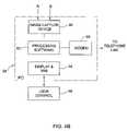
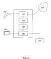
- a system for carrying out the method of the inventioncomprises:
- Systemcan be connected to any suitable display such as a screen or a printer, for example, for visually presenting the manipulated entities.
- Systemcan be also connectable to an additional utility such as a virtual treatment system, for example for designing a virtual orthodontic treatment.
- FIG. 1illustrates the main elements of embodiments of devices for creating a three-dimensional color numerical entity that is manipulated according to the present invention.
- FIGS. 2A , 2 B, 2 Cgraphically illustrates the creation of a three dimensional color entity from a three dimensional monochrome entity and a two dimensional color entity.
- FIG. 3graphically illustrates an alignment procedure according to the invention for aligning the X-Y coordinates of a three dimensional monochrome entity with corresponding coordinates of a two dimensional color entity.
- FIGS. 4A and 4Bschematically illustrate the main elements of a portion of a device used for providing a three dimensional monochrome entity.
- FIGS. 5A , 5 B, 5 Cillustrate in plan view, side view and isometric view, respectively, a probe used in first embodiment of the device of FIG. 1 to provide a two dimensional color entity.
- FIG. 6illustrates in side view a sheath for a probe used in second embodiment of the device of FIG. 1 to provide a two dimensional color entity.
- FIG. 7Aillustrates in side view a probe used in third embodiment of the device of FIG. 1 to provide a two dimensional color entity.
- FIG. 7Billustrates the transmission and reflection characteristics of a typical dichroic coating used in the probe of FIG. 7A .
- FIG. 8illustrates in side view the general arrangement of the main elements used in fourth embodiment of the device of FIG. 1 to provide a two dimensional color entity.
- FIG. 9illustrates an LED arrangement used with the embodiment of FIG. 8 .
- FIG. 10illustrates an alternative illumination arrangement used with the embodiment of FIG. 8 .
- FIG. 10Aillustrates details of the tri-color disc used with the illumination arrangement of FIG. 10 .
- FIG. 11illustrates in side view the general arrangement of the main elements used in fifth embodiment of the device of FIG. 1 to provide a two dimensional color entity.
- FIG. 12illustrates in side view the general arrangement of the main elements used in sixth embodiment of the device of FIG. 1 to provide a two dimensional color entity.
- FIG. 13illustrates in side view the general arrangement of the main elements used in seventh embodiment of the device of FIG. 1 to provide a two dimensional color entity.
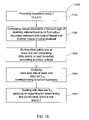
- FIG. 14illustrates the main steps of the method according to the first embodiment of the present invention.
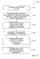
- FIG. 15illustrates the main steps of the method according to the second embodiment of the present invention.
- FIG. 16illustrates the main steps of the method according to the third embodiment of the present invention.
- FIG. 17illustrates the main steps of the method according to the fourth embodiment of the present invention.
- FIG. 18illustrates a portion of the intraoral cavity on which it is desired to implant a dental prosthesis.
- FIG. 19schematically illustrates a transformation step according to the method of FIG. 17 .
- FIG. 20is a block diagram of a system according to an embodiment of the present invention.
- the first step of the method according to the present inventionrelates to providing at least one numerical entity that is representative of the three-dimensional surface geometry and color of at least part of the intra-oral cavity.
- the said numerical entityis typically at least “four-dimensional”, that is, each data point of the data set comprises at least four prime independent variables.
- three of the prime independent variablesrelate to spatial coordinates of a surface, typically defined along orthogonal. Cartesian axes, x, y, z. Alternatively, these variables may be defined along polar axes or any other geometric system in which a surface may be described.
- the fourth prime independent variablerefers to a color parameter that is expressed numerically and associated with the spatial coordinates.
- the color parametermay itself be comprised of independent prime color variables—for example relating to the red, blue and green (RGB) components associated with the color parameter.
- the color parametermay be expressed in terms of the Hue, Saturation and Intensity (HIS).
- any other color parametermay be used, including parameters that provide a measure of internal reflectance and translucency, or any other optical property of teeth.
- the numerical entitymay comprise a data set of a plurality of 4-dimensional arrays—(x, y, z, c), wherein each array represents the x, y, z, geometrical coordinates and the color c of a point on a surface within the intra-oral cavity.
- any suitable meansmay be used to provide the numerical entity.
- a three-dimensional surface scanner with color capabilitiesmay be used.
- such a scannermakes use of confocal imaging for providing an accurate three-dimensional representation of the target surface within the intra-oral cavity. Color values are then added to each data point of this data set by obtaining a two-dimensional color image of the target surface, and then mapping the color values of the two-dimensional image onto the three-dimensional “image”.
- FIG. 1illustrates the general relationship between the various elements of a device for providing a 3D color numerical entity, generally designated with the numeral 100 , according to the embodiments of the device described herein.
- the device 100comprises a main illumination source 31 for illuminating the object of interest 26 , typically a part of the intraoral cavity, and is optically coupled to main optics 41 to provide depth Z values for an array range of X-Y points (according to a known frame of reference) along the surface of the object 26 .
- Detection optics 60comprises an image sensor, typically a CCD, that is preferably monochromatic to maximise the resolution of the device, and which typically defines the X-Y frame of reference. Alternatively, the CCD may be adapted to receive color images.
- the detection optics 60receives image data from the main optics 41 and the image processor 24 determines the depth Z values for each X-Y point illuminated on the object 26 based on this image data. In this manner, a manipulable three-dimensional numerical entity E comprising the surface coordinates of the object 26 .
- the device 100further comprises color illuminating means, such as for example a tri-color sequence generator 74 , for selectively illuminating the object 26 with suitable colors, typically Green, Red and Blue, and for each such monochromatic illumination, a two dimensional image of the object 26 is captured by the detection optics 60 .
- the processor 24then processes the three differently colored monochromatic images and combines the same to provide a full color 2D image of the object.
- the device 100is configured for providing color data for an array of X-Y points that is according to the same frame of reference as the X-Y array used for obtaining the 3D entity.
- the processor 24aligns the 2D color image with the 3D entity previously created, and then provides color values to this entity by mapping color values to the entity at aligned X-Y points. Such alignment is straightforward because both the 3D data and the 2D color data are referenced to the same X-Y frame of reference.
- the mapping procedureis performed as follows.
- a three-dimensional numerical entity Eis obtained by determining depth Z-values for a grid of X-Y points, illuminated via main optics 41 and determined by image processor 24 .
- the entity Ethus comprises an array of (X, Y, Z) points, as illustrated in FIG. 2A .
- the X-Y plane of entity Eis substantially parallel to the sensing face of the image sensing means of the detection optics 60 , typically a CCD. Almost concurrently, i.e., either just before or just after the readings for determining the 3D entity E are obtained by the detection optics 60 , a 2D color image of the object 26 is taken using the same detection optics 60 , at substantially the same relative spatial disposition between the detection optics 60 and the object 26 , FIG. 2B . If a monochromatic CCD is used, the 2D color image obtained is a composite created from three separate monochromatic images, each provided by illuminating the object 26 with a different color, such as for example red, green and blue.
- the 2D color imagethus corresponds to another entity N comprised of the location and color value of each pixel forming this image, (X′, Y′, C).
- the X′-Y′ coordinates of the pixelsare on a plane substantially parallel to the X-Y plane of the entity E, and furthermore these coordinates represent substantially the same part of the object 26 as the X-Y coordinates of entity E.
- the reason for thisis that the optical information that is used for creating both the 3D entity E and the color 2D entity N are obtained almost simultaneously with a very small time interval therebetween, and typically there is insufficient time for any significant relative movement between the image plane of the detection optics 60 and the object 26 to have occurred between the two scans.
- such an alignment proceduremay be based on optical character recognition (OCR) techniques.
- OCRoptical character recognition
- the X-Y coordinates of entity Ecan be divided up into two groups, one group comprising Z values corresponding to the depth of the object, and a second group for which no reasonable Z value was found, and this group corresponds to the background relative to object 26 .
- the profiles of shapes represented by the X-Y coordinates of the first group of entity E, herein referred to as another entity E′are then optically compared with profiles of shapes corresponding to the X′-Y′ coordinates of entity N, herein referred to as another entity N′.
- entity E′is translated or rotated (coplanarly) with respect to entity N′ until a best fit between the optical shapes between the two entities is obtained, using OCR techniques that are well known in the art.
- the image processoror another computer, will attempt to align the outer border of the object 26 as seen along the Z-axis and encoded in entity E with optical elements in the 2D color image encoded in entity N. Thereafter, the color value C of each X′-Y′ coordinate of entity N is mapped to the appropriate data point of entity E having the aligned X-Y coordinates corresponding thereto.
- the color mapping operation to create entity Imay be executed by any suitable microprocessor means, typically processor 24 of the device 100 ( FIG. 4B ).
- FIGS. 4A and 4Billustrate, by way of a block diagram an embodiment of a system 20 for confocal imaging of a three dimensional structure according to WO 00/08415 assigned to the present assignee, the contents of which are incorporated herein.
- any suitable confocal imaging arrangementmay be used in the present device.
- the system 20comprises an optical device 22 coupled to a processor 24 .
- Optical device 22comprises, in this specific embodiment, a semiconductor laser unit 28 emitting a laser light, as represented by arrow 30 .
- the lightpasses through a polarizer 32 which gives rise to a certain polarization of the light passing through polarizer 32 .
- the lightthen enters into an optic expander 34 which improves the numerical aperture of the light beam 30 .
- the light beam 30then passes through a module 38 , which may, for example, be a grating or a micro lens array which splits the parent beam 30 into a plurality of incident light beams 36 , represented here, for ease of illustration, by a single line.
- the operation principles of module 38are known per se and the art and these principles will thus not be elaborated herein.
- the optical device 22further comprises a partially transparent mirror 40 having a small central aperture. It allows transfer of light from the laser source through the downstream optics, but reflects light traveling in the opposite direction. It should be noted that in principle, rather than a partially transparent mirror other optical components with a similar function may also be used, e.g. a beam splitter.
- the aperture in the mirror 40improves the measurement accuracy of the apparatus. As a result of this mirror structure the light beams will yield a light annulus on the illuminated area of the imaged object as long as the area is not in focus; and the annulus will turn into a completely illuminated spot once in focus. This will ensure that a difference between the measured intensity when out-of- and in-focus will be larger.
- Another advantage of a mirror of this kind, as opposed to a beam splitteris that in the case of the mirror internal reflections which occur in a beam splitter are avoided, and hence the signal-to-noise ratio improves.
- the unitfurther comprises a confocal optics 42 , typically operating in a telecentric mode, a relay optics 44 , and an endoscopic probing member 46 .
- Elements 42 , 44 and 46are generally as known per se. It should however be noted that telecentric confocal optics avoids distance-introduced magnification changes and maintains the same magnification of the image over a wide range of distances in the Z direction (the Z direction being the direction of beam propagation).
- the relay opticsenables to maintain a certain numerical aperture of the beam's propagation.
- the endoscopic probing member 46typically comprises a rigid, light-transmitting medium, which may be a hollow object defining within it a light transmission path or an object made of a light transmitting material, e.g. a glass body or tube.
- the endoscopic probetypically comprises a mirror of the kind ensuring a total internal reflection and which thus directs the incident light beams towards the teeth segment 26 .
- the endoscope 46thus emits a plurality of incident light beams 48 impinging on to the surface of the teeth section.
- Incident light beams 48form an array of light beams arranged in an X-Y plane, in the Cartesian frame 50 , propagating along the Z axis.
- the illuminated spots 52are displaced from one another along the Z axis, at different (X i ,Y i ) locations.
- spots at other locationsmay be out-of-focus. Therefore, the light intensity of the returned light beams (see below) of the focused spots will be at its peak, while the light intensity at other spots will be off peak.
- a plurality of measurements of light intensityare made at different positions along the Z-axis and for each of such (X i ,Y i ) location, typically the derivative of the intensity over distance (Z) will be made, the Z i yielding maximum derivative, Z 0 , will be the in-focus distance.
- the distance derivativewill be larger when approaching in-focus position thus increasing accuracy of the measurement.
- the light scattered from each of the light spotsincludes a beam traveling initially in the Z-axis along the opposite direction of the optical path traveled by the incident light beams.
- Each returned light beam 54corresponds to one of the incident light beams 36 . Given the unsymmetrical properties of mirror 40 , the returned light beams are reflected in the direction of the detection optics 60 .
- the detection optics 60comprises a polarizer 62 that has a plane of preferred polarization oriented normal to the plane polarization of polarizer 32 .
- the returned polarized light beam 54pass through an imaging optic 64 , typically a lens or a plurality of lenses, and then through a matrix 66 comprising an array of pinholes.
- CCD camerahas a matrix or sensing elements each representing a pixel of the image and each one corresponding to one pinhole in the array 66 .
- the CCD camerais connected to the image-capturing module 80 of processor unit 24 .
- processor 24each light intensity measured in each of the sensing elements of the CCD camera is then grabbed and analyzed, in a manner to be described below, by processor 24 .
- Unit 22further comprises a control module 70 connected to a controlling operation of both semi-conducting laser 28 and a motor 72 .
- Motor 72is linked to telecentric confocal optics 42 for changing the relative location of the focal plane of the optics 42 along the Z-axis.
- control unit 70induces motor 72 to displace the optical element 42 to change the focal plane location and then, after receipt of a feedback that the location has changed, control module 70 will induce laser 28 to generate a light pulse.
- image-capturing module 80to grab data representative of the light intensity from each of the sensing elements. Then in subsequent sequences the focal plane will change in the same manner and the data capturing will continue over a wide focal range of optics 44 .
- Image capturing module 80is connected to a CPU 82 , which then determines the relative intensity in each pixel over the entire range of focal planes of optics 42 , 44 . As explained above, once a certain light spot is in focus, the measured intensity will be maximal. Thus, by determining the Z i corresponding to the maximal light intensity or by determining the maximum displacement derivative of the light intensity, for each pixel, the relative position of each light spot along the Z-axis can be determined. Thus, data representative of the three-dimensional pattern of a surface in the teeth segment, can be obtained. This three-dimensional representation may be displayed on a display 84 and manipulated for viewing, e.g. viewing from different angles, zooming-in or out, by the user control module 86 (typically a computer keyboard).
- the user control module 86typically a computer keyboard
- the device 100further comprises means for providing a 2D color image of the same object 26 , and any suitable technique may be used for providing the color image. A number of such techniques are described below.
- the first techniqueis based on illuminating the object 26 sequentially with three different colored lights such as red, green and blue, and capturing a monochromatic image corresponding to each color via CCD 68 and the image capture device 80 (see FIGS. 4A , 4 B).
- tri-color light sources 71i.e., one or more light sources that provide illuminating radiations to the object 26 in a plurality of different colors, are coupled to a tri-color sequence generator 74 , which are suitably controlled by the processing unit 24 to provide the three colored illuminations via delivery optics 73 in a predetermined sequence.
- the colored illuminationsare provided at a relative short time interval, typically in the range of about 0 to 100 milliseconds, I some cases being in the order of 50 milliseconds, with respect to the 3D scan, directly before or after the same.
- Suitable processing software 82combines the three images to provide a 2D color image comprising an array of data points having location (X,Y) and color (C) information for each pixel of the 2D color image.
- the delivery optics 73is integral with endoscope 46 , which is in the form of a probing member 90 , as illustrated in FIGS. 5A , 5 B and 5 C.
- the probing member 90is made of a light transmissive material, typically glass and is composed of an anterior segment 91 and a posterior segment 92 , tightly glued together in an optically transmissive manner at 93 .
- Slanted face 94is covered by a totally reflective mirror layer 95 .
- Glass disk 96 defining a sensing surface 97may be disposed at the bottom in a manner leaving an air gap 98 . The disk is fixed in position by a holding structure which is not shown.
- Three light raysare 99 from the main optics 42 are represented schematically. As can be seen, they bounce at the walls of the probing member at an angle in which the walls are totally reflective and finally bounce on mirror 95 and reflected from there out through the sensing face 97 .
- the light raysfocus on focusing plane 101 , the position of which can be changed by the focusing optics (not shown in this figure).
- the probe member 90comprises an interface 78 via which optical communication is established with the relay optics 44 and the remainder of the device 100 .
- the probe 90further comprises a plurality of tri-color LED's 77 , for providing the colored illumination to the object 26 .
- the LED's 77typically comprise different LED's for providing blue radiation and green radiation when red illuminating radiation is used as the illumination source 31 for the main optics 41 when creating the 3D entity.
- the LED's 77may comprise green and red LED's, and if a green illuminating radiation is used as the illumination source 31 , LED's 77 may comprise blue and red LED's.
- the tri-color LED's 77are each capable of providing an illumination radiation in one of three colors, typically red, green or blue, as controlled via the tri-color sequence generator. Alternatively, a plurality of LED's in three groups, each group providing illumination in one of the desired colors, may be provided.
- the LED's 77are located at the periphery of the interface 78 such that the LED's do not interfere with the other optical operations of the device 100 . In particular such operations include the transmission of the illuminating radiation for the confocal focusing operations, and also the transmission of reflected light from the object 26 to the main optics 41 to provide the 3D entity or the 2D color entity.
- the LED'sare mounted substantially orthogonally with respect to the interface 78 , and thus, as illustrated in FIG. 5C , light from each of the LED's 77 is transmitted by internal reflection with respect to the walls of the probe 90 , to the user interface end 79 of the probe.
- the device 100 according to a variation of the first embodimentis further adapted for providing improved precision of the color data obtained therewith, in a similar manner to that described herein for the fourth embodiment, mutatis mutandis.
- the endoscope 46is also in the form of a probing member 90 , substantially as described with respect to the first embodiment, but with the difference that there are no LED's directly mounted thereon at the interface 78 , mutatis mutandis.
- the delivery optics 73is in the form of a disposable sleeve, shroud or sheath 190 that covers the outer surface the probing member 90 , as illustrated in FIG. 6 .
- the sheath 190is made from a waveguiding material, such as an acrylic polymer for example, capable of transmitting an illuminating radiation from the upstream face 191 of the sheath 190 therethrough and to the downstream face 192 thereto.
- the upstream face 191is in the form of a peripheral surface around the interface 78 .
- the downstream face 192is formed as a peripheral projection surrounding a window 193 comprised in said sheath 190 .
- the window 193is in registry with the user interface end 79 of the probe 90 .
- a plurality of tri-color LED's 177 for providing the colored illumination to the object 26are mounted on the device 100 just upstream of the sheath 190 .
- the tri-color LED's 177are each capable of providing an illumination radiation in one of three colors, typically red, green or blue, as controlled via the tri-color sequence generator 74 .
- a plurality of LED's in three groups, each group providing one colored illuminationmay be provided.
- the LED's 177are located outside of the main optics of the device 100 , and thus the LED's do not interfere with the other optical operations of the device 100 in particular including the transmission of the illuminating radiation for the confocal focusing operations, or in the transmission of reflected light from the object 26 to provide the 3D entity or the 2D color entity.
- the LED'sare mounted substantially opposite to the upstream face 191 , and thus, as illustrated in FIG. 6 , light from each of the LED's 177 is transmitted by the waveguiding sheath 190 to downstream face 192 and thence to the object 26 .
- the sheath 190is particularly useful in maintaining hygienic conditions between one patient and the next, and avoids the need for sterilizing the probe 90 , since the sheath may be discarded after being used with one patient, and replaced with another sterilised sheath before conducting an intra-oral cavity survey with the next patient.
- the device 100 according to a variation of the second embodimentis further adapted for providing improved precision of the color data obtained therewith, in a similar manner to that described herein for the fourth embodiment, mutatis mutandis.
- a red lasermay be used as the illumination source 28 for the main optics when creating the 3D entity.
- this illumination meansmay also be used to obtain the red monochromatic image for the creation of the 2D color image, by illuminating the object 26 and recording the image with the optical detector 60 .
- the illumination source for the main optics 41is a green or blue laser, wherein illuminating radiations in only the remaining two colors need to be provided, mutatis mutandis.
- the endoscope 46is also in the form of a probing member 90 , substantially as described with respect to the second embodiment with the following differences, mutatis mutandis.
- the delivery optics 73comprises a plurality of LED's 277 for providing the colored illumination to the object 26 .
- a red laseris used as the illumination source for the main optics when creating the 3D entity.
- this illumination meansis also used to obtain the red monochromatic image for the creation of the 2D color image.
- the LED's 277are each capable of providing an illumination radiation in either green or blue, as controlled via the tri-color sequence generator 74 .
- the LED's 277are located on the outer side of slanted face 94 , and thus the LED's do not interfere with the other optical operations of the device 100 in particular including the transmission of the illuminating radiation for the confocal focusing operations, or in the transmission of reflected light from the object 26 to provide the 3D entity or the 2D color entity.
- the slanted face 94comprises a dichroic coating 278 on the outer side thereof, which has relatively high reflectivity and low transmission properties with respect to red light, while having substantially high transmission characteristics for blue light and green light, as illustrated in FIG. 7B .
- each of the blue or green LED's 277is transmitted, in turn, through the dichroic coating to interface 79 and thence to the object 26 , as controlled by the generator 74 .
- the dichroic coatingpermits internal reflection of the red radiation from the main optics 41 to the interface 79 and object 26 , and thus allows the 3D scan to be completed, as well as allowing the red monochromatic image of the object 26 to be taken by the device 100 .
- tricolor LED'smay be used, and properly synchronized to illuminate with either green or blue light as controlled by generator 74 .
- the illumination source for the main optics 41may be a green or blue laser, in which case the LED's are each capable of providing illumination in the remaining two colors, and in such cases the dichroic coating is adapted for allowing transmission of these remaining two colors while providing substantially high reflection for the illuminating laser of the main optics, in a similar manner to that described above for the red laser, mutatis mutandis.
- tri-color illuminationis provided within the main focal optics 42 , in particular at the confocal system aperture stop, and facing the objective lens of the system.
- An advantage provided by this form of illuminationis that the tri-color illumination illuminates the object 26 through the downstream objective lens 142 in nearly collimated light, and thus the object illumination is highly uniform.
- the tri-color light sources 377may be mounted statically on the physical aperture stop at the aperture stop plane 150 , or alternatively they may be mounted on a retracting aperture stop, which also serves to stop down the system aperture in preview mode. In this embodiment, by placing the tri-color light sources 377 at the aperture stop plane, wherein the light beam from the illumination source 31 narrows to a minimum within the main optics 41 , the external dimensions of the device 100 may still remain relatively compact.
- the tri-color light sources 377may comprise, for example, a plurality of tri-color LED's 385 mounted onto a bracket 380 .
- the bracket 380is typically annular, having a central aperture to allow illumination light from the illuminating unit 31 to pass therethrough and to the object 26 , and to allow light coming from the object 26 to pass therethrough and to the detection optics 60 , without being affected by the bracket 380 .
- the bracket 380positions the LED's in the required location upstream of objective lens 166 .
- the LED'sare arranged in a spaced radial and circumferential manner as illustrated in FIG. 9 to provide the most uniform illumination of the object 26 possible with this arrangement.
- a red laseris used as the illumination source 31 for the main optics 41 when creating the 3D entity.
- this illumination meansis also used to obtain the red monochromatic image for the creation of the 2D color image.
- the LED's 385are each capable of providing an illumination radiation in either green or blue, as controlled via the tri-color sequence generator 74 .
- the illumination source for the main optics 41may be a green or blue laser, in which case the LED's 385 are each capable of providing illumination in the remaining two colors, in a similar manner to that described above for the red laser, mutatis mutandis.
- tricolor LED'smay be used, and properly synchronized to illuminate with either green or blue light as controlled by generator 74 .
- the LED's 385may be used to provide, sequentially, all the required colored illuminations, typically red, green and blue.
- the LED's 385each provide illumination in one of at least three colors. Thus, some of the LED's 385 provide a blue illumination, while other LED's 385 provide green illumination, while yet other LED's 385 provide red illumination.
- the device 100 according to a variation of the fourth embodimentis further adapted for providing improved precision of the color data obtained therewith.
- the device 100 according to this variation of the fourth embodimentis adapted such that the tri-color light sources 377 each illuminate the object 26 with as wide a depth of field as possible, i.e., at a low numerical aperture.
- each set of light sources 377 of the same color, for example blueilluminates a particular depth of the object 26 in the z-direction while substantially in focus.
- the numerical aperture of the confocal system itselfis relatively high to maximize accuracy of the depth measurements, and thus provides a relatively narrower depth of field.
- the optical system downstream of the light sources 377in this embodiment the objective lens 166 , is chromatic, and in particular maximizes the chromatic dispersion therethrough.
- a chromatic dispersion elementfor example an optically refractive block of suitable refractive index, may be provided along the optical path between the light sources 377 and the object 26 .
- each one of the different-colored light sources 377illuminates a different portion of the object 26 along the z-direction.
- the light sources 377 providing the blue illuminationilluminate in focus a portion of the object 26 closest to the device 100
- the light sources 377 providing the red illuminationilluminate in focus a portion of the object 26 furthest from the device 100 .
- the light sources 377providing the green illumination illuminate in focus a portion of the object 26 intermediate the blue and red portions, and a non-illuminated gap may exists between the red and green, and between the green and blue illuminated portions, the depth of these gaps depending on the dispersion characteristics of the downstream optics.
- the light sources 377are also adapted for providing illumination in colors intermediate in wavelengths such as to illuminate the aforesaid gaps in focus.
- the LED's 385may be adapted for providing both such additional colored illumination, or some of the LED's 385 may be adapted to provide colored illumination at a first intermediate wavelength, while another set of LED's 385 may be adapted to provide colored illumination at a second intermediate wavelength.
- the first intermediate wavelengthprovides an illumination in aqua, and thus illuminates in focus at least a part of the gaps between the blue and green illuminated focused zones of the object 26
- the second intermediate wavelengthprovides an illumination in amber, and thus illuminates in focus at least a part the gaps between the green and red illuminated focused zones.
- additional light sourcesmay be used to provide further intermediate wavelengths and thus provide further depth cover illumination, in focus, of the object.
- the device 100is used as a viewfinder, typically prior to taking a depth and color scan of the object 26 , the above arrangement using at least five different colored illuminations at a low numerical aperture, enables a much clearer and focused real-time color image of the object 26 to be obtained.
- viewfinder modealso known as “aiming mode”
- the device 100 according to this variation of the fourth embodimentrepeatedly illuminates the object 26 in cycles, wherein in each cycle the object 26 is separately illuminated in each of the five colors blue, aqua, green, amber, red, in quick succession, and each time a monochromatic image is obtained by the monochromatic image sensor in 60 .
- Each set of five monochromatic imagesis then analysed to provide a composite color image, and this image is then displayed in substantially real time in the viewfinder display window in the control software, so that the succession of such composite images gives the appearance of a substantially real-time color video feed of the object 26 .
- Each of the monochrome images in any particular setcorresponds to a particular illumination color or wavelength, and thus the zone(s) of the object 26 within the depth of field corresponding to this illumination will be in focus, while the other parts of the object 26 will appear out of focus.
- each such image in the aforesaid set of imageswill contain a portion which has high precision focused image of a part of the object, for the particular illumination wavelength.
- the imagesare combined in such a way as to maximize the precision of the focused image and corresponding color thereof.
- suitable algorithmsmay be applied to each of the five images of a set to distinguish between the focused and unfocused the areas thereof.
- Such algorithmsmay employ, for example, techniques which apply FFT techniques to areas of the images, and which search for high frequency portions which correspond to focused areas.
- FFT techniquesmay be applied to areas of the images, and which search for high frequency portions which correspond to focused areas.
- such algorithmsas well as software and hardware to accomplish the same are well known in the art.
- the focused areas of each of the five imagesare merged to provide a monochrome composite substantially focused image of the object.
- the images obtained using the red, green and blue illuminationsare combined and converted to a corresponding luminescence/chroma (Y/C) image, and techniques for doing so are well known in the art.
- the luminescence component of the luminescence/chroma (Y/C) imageis replaced with the aforesaid corresponding composite focus image, and the resulting new luminescence/chroma image is then transmitted to the display in the viewfinder.
- red, green and blue imagesare preferably first scaled to compensate for magnification effects of the different wavelengths.
- the green image, and more so the blue imageneeds to be scaled up to match the red image.
- the device 100When the user is ready to take a depth and color scan of the object 26 , having steered the device 100 into position with the aid of the viewfinder, the device 100 takes a depth scan in the z-direction as described herein, and either before or after the same, but in quick succession one with the other, takes a color scan in a similar manner to that described above for the viewfinder mode, mutatis mutandis. Subsequently, the color data and the depth data of the two scans can be combined to provide the full spatial and color data for the surface scanned.
- one or more color scansmay also be taken during the depth scan, and/or at the beginning and at the end of the depth scan.
- the depth scanis obtained by displacing the objective lends 166 along the z-direction in a continuous or stepped motion.
- Multiple color scanscan then be obtained by associating the color sources 377 with the objective lens, so that these are also displaced along the z-direction.
- the green and red illuminationsmay be discarded or otherwise manipulated to provide a composite color image at this station.
- a plurality of color imagescan be obtained, each based on a different z-position, so that each illumination wavelength is used to illuminate in focus a different part (depth) of the object 26 .
- suitable algorithmsmay be used to form a composite color image of the set of color images associated with a particular z-scan of the object 26 to provide even more precise and accurate color image, than can then be combined with the depth data.
- the tri-color light sources 377may be replaced with a rotating filter illumination system 400 .
- the system 400comprises a while light source 410 , such as for example white phosphorus InGaN LED's, and the light therefrom is focused onto an optical fiber bundle 420 by means of condenser optics 430 . Between the condenser optics 430 and the fiber bundle 420 is provided a rotating tri-color filter 450 .
- the filter 450is divided into three colored sections, comprising blue, green and red filters on adjacent sectors therein.
- the fiber bundle 420is flared at the downstream end 470 to form the desired illumination pattern.
- downstream end 470 of the fibersmay be mounted onto an annular bracket similar to bracket 380 illustrated in FIG. 9 , at the aperture stop plane of the confocal optics.
- a suitable motor 460typically a stepper motor for example, drives the rotating filter such as to sequentially present each colored filter to the light passing from the condenser optics 430 to the fiber bundle 420 , as synchronized with the sequence generator 74 ( FIG. 1 ) to enable the detection optics 60 to capture images of the object 26 when selectively illuminated with each of the three colors.
- the rotating filter 450only requires to comprise the remaining two colors, as discussed above for similar situations regarding the LED's, mutatis mutandis.
- the device 100 according to this variation of the fourth embodimentmay be further adapted for providing improved precision of the color data obtained therewith, in a similar manner to that described herein for another variation of fourth embodiment, mutatis mutandis.
- the filter 450is divided into five (or more if desired) colored sections, comprising blue, aqua, green, amber and red filters on adjacent sectors therein.
- a fifth embodiment of system 100is substantially similar to the fourth embodiment as described herein, with the following difference, mutatis mutandis.
- polarizerare provided at two locations in order to increase the image contrast.
- a first polarizing element 161is located just downstream of the light sources 377 so as to polarize the light emitted from the light sources 377 .
- a second polarizing element 162is located just upstream of the image sensor of the detection optics 60 , and is crossed with respect to the first polarizing element 161 .
- a quarter waveplate 163is provided just upstream of the object 26 , i.e. at the downstream end of the endoscope 46 ( FIG. 4A ).
- the first polarizing element 161is typically annular, having a central aperture to allow illumination light from the illuminating unit 31 to pass therethrough and to the object, and to allow light coming from the object 26 to pass therethrough and to the detection optics 60 , without being affected by the polarizing element 161 .
- light that is reflected from the object 26returns to the main confocal optics 42 in a crossed polarization state due to the effect of the quarter waveplate 163 , and thus reaches the detection optics 60 at substantially full intensity.
- any light reflected from the objective lens 166 of the confocal optics 42is reflected at the same polarization state, and is therefore filtered out by the crossed polarizing element 162 .
- This arrangementserves as an effective signal to ghost enhancement system.
- the device 100 according to a variation of the fifth embodimentis further adapted for providing improved precision of the color data obtained therewith, in a similar manner to that described herein for the fourth embodiment, mutatis mutandis.
- a sixth embodiment of the system 100is substantially as described for the fourth embodiment, with the following difference, mutatis mutandis.
- the tri-color light sources 377are replaced with a rotating filter illumination system 500 .
- the system 500comprises a while light source 510 , such as for example white phosphorus InGaN LED's, and the light therefrom is focused onto a mirror 520 by means of condenser optics 530 .
- a rotating tri-color filter 550which is similar to the filter 450 illustrated in FIG.
- the optical axis OA of the confocal optics 41is orthogonal to the optical axis OA′ of the light source 510 and condenser optics 530 .
- the mirror 520is mounted between the aperture stop plane and the objective lens 166 of the confocal optics, and at an angle to the optical axis OA thereof and to the optical axis OA′ of the light source 510 and condenser optics 530 .
- the mirror 520is typically annular, having a central aperture aligned with optical axis OA to allow illumination light from the illuminating unit 31 to pass therethrough and to the object 26 , and to allow light coming from the object 26 to pass therethrough and to the detection optics 60 , without being affected by the mirror 520 .
- the mirror 520has sufficient reflecting surface to reflect light from the source 510 via objective lens 166 and to the object 26 .
- the rotating filter 550only requires the remaining two colors, as discussed above for similar situations, mutatis mutandis.
- the device 100 according to a variation of the sixth embodimentis further adapted for providing improved precision of the color data obtained therewith, in a similar manner to that described herein for the fourth embodiment, mutatis mutandis.
- a seventh embodiment of the system 100comprises a white light illumination system 600 , illustrated in FIG. 13 .
- the system 600comprises a while light source 610 , such as for example white phosphorus InGaN LED's, and the light therefrom is directed onto a flip mirror 620 via a polarizing beam splitter 650 by means of condenser optics 630 .
- the optical axis OA of the confocal optics 41is orthogonal to the optical axis OA′′ of the light source 610 and condenser optics 630 .
- the mirror 620is mounted between the aperture stop plane 155 and the objective lens 166 of the confocal optics, and at an angle to the optical axis OA thereof and to the optical axis OA′′ of the light source 610 and condenser optics 630 .
- the mirror 620is adapted to flip away from optical axis OA when the device 100 is being used for obtaining the 3D entity E. This allows illumination light from the illuminating unit 31 to pass therethrough and to the object 26 , and to allow light coming from the object 26 to pass therethrough and to the detection optics 60 , without being affected by the mirror 620 . When it is desired to take a 2D color image, the mirror 620 is flipped down to the position shown in FIG. 13 . Polarizing beam splitter 650 that polarizes white light from the source 610 and allows the same to pass therethrough and to mirror 620 , and thence to the object 26 via the confocal objective 166 and broadband quarter wave plate 163 .
- the CCD of the detection optics 60is a color CCD and is also used for the 2D scan.
- flipping mirror 620is replaced with a fixed mirror having a central aperture similar to mirror 520 , having a central aperture, as described for the sixth embodiment, mutatis mutandis.
- the image capture device 80 and processing software 82( FIG. 4 b ) automatically provide a 2D color image comprising an array of data points having location (X,Y) and color (C) information for each pixel of the image.
- the objectis illuminated with a white light, and the light reflected from the object 26 is passed sequentially through one of three different colored filters such as red, green ad blue.
- Suitable processing software 82combines the three images to provide a 2D color image comprising an array of data points having location (X,Y) and color (C) information for each pixel of the image.
- the main illumination source 31 of device 100comprises suitable means for providing the three different colored illuminations.
- the illumination source 31comprises three different lasers, each one providing an illumination radiation at a different desired color, red green or blue.
- a suitable white light illumination meansis provided, coupled to a suitable rotating tri-color filter, similar to the filters described above, mutatis mutandis.
- suitable control meansare provided, adapted to illuminate the object 26 with each colored radiation in turn, and the 2D colored image is obtained in a similar fashion to that described above, mutatis mutandis.
- the objectis also illuminated with one of the colored illuminations in order to provide the 3D surface topology data.
- the illumination radiation that is used for obtaining the 2D color imageis injected into the optical axis OA of the confocal optics 42 without affecting the operation thereof or degrading the 3D image capture.
- the endoscope 46 , the illumination unit 31 , the main optics 41 , color illumination 71 and tri-color sequence genetratorare preferably included together in a unitary device, typically a hand-held device.
- the devicepreferably includes also the detector optics 60 , though the latter may be connected to the remainder of the device via a suitable optical link such as a fiber optics cable.
- the data representative of the surface topology and color, i.e., entity Imay be transmitted through an appropriate data port, e.g. a modem 88 ( FIG. 4B ), through any communication network, e.g. telephone line 90 , to a recipient (not shown) e.g. to an off-site CAD/CAM apparatus (not shown).
- an appropriate data porte.g. a modem 88 ( FIG. 4B )
- any communication networke.g. telephone line 90
- a recipiente.g. to an off-site CAD/CAM apparatus (not shown).
- an accurate color three-dimensional representation of the teeth segmentmay be reconstructed. This may allow a virtual reconstruction of the three-dimensional structure in a computerized environment or a physical reconstruction in a CAD/CAM apparatus.
- the devicemay comprise any other confocal focusing arrangement, for example as described in WO 00/08415.
- any suitable means for providing 3D scanningcan be used so long as the 3D scan and the color 2D scan correspond substantially to the same object or portion thereof being scanned, and the same frames of references are maintained.
- the scansare executed in relatively quick succession, and by the same or different image capturing means such as CCD's that are arranged such that the color 2D image substantially corresponds to the 3D entity. This enables color values at particular x, y coordinates of the 2D color image to be matched to the same x, y coordinates of the 3D image which also have a z coordinate.
- the method of the inventionis particularly adapted for automatically differentiating one tissue from another tissue within the oral cavity.
- the first step 1110is to obtain numerical entity I comprising a data set representing the surface geometry and color of at least the portion of the intraoral cavity that contains the area of interest, herein referred to as the target surface.
- the target surfacetypically comprises both hard tissues, such as the teeth, and soft tissues which include at least one of the gums, tongue, cheeks and lips.
- Each data point in the numerical entity Icomprises surface coordinates of the tissue, typically expressed as Cartesian (x, y, z) coordinates, plus a color parameter relating to the color c of the tissue at these surface coordinates.
- the color value for ccan be conveniently expressed in component form in terms of the red, green and blue components (RGB), and in particular in terms of a color component coefficient.
- RGBred, green and blue components
- a red coefficient ratio: Rcmay be defined as the intensity of the red component divided by the average intensity of the red, green and blue components, and is useful in differentiating between the hard and soft tissues.
- the entity Imay be obtained, for example, using the device described herein with respect to FIGS. 1 to 13 .
- the value of the color parameter cis analysed for each data point in I, and compared with at least one color criterion, and typically with at least two color ranges R 1 , R 2 .
- the ranges R 1 , R 2each represent the values of the color parameter expected for one or another of the two tissues, such as the teeth and gums.
- the color range R 1 for the teethwill include values for c typically associated with the hard tissues including the teeth, comprising all appropriate shades appropriate for enamel, dentine, pulp and other parts of teeth.
- the color range R 2 for the soft tissueswill include values for c typically associated with gums, cheeks, lips and the tongue including all appropriate shades of pink and red associated with these tissues, including when the tissues are at least partially drained of blood, as may happen, for example when the tissues are anaesthetised. In some cases it may be appropriate to compare the value of the color parameter c with a specific value, for example a single (R, G, B) or Rc value, rather than a range of values.
- Table Ilists typical RGB values measured for gums, lips and teeth of a particular patient. As may be seen from Table I, values of Rc significantly greater than unity indicate that the red component is dominant, which is the case for soft tissues in general. Hard tissues, on the other hand, have a more even distribution of color components, resulting in an Rc value very close to unity.
- an exemplary range for R 1may be from about 0.9 to about 1.1, while an exemplary range for R 2 may be from less than about 1.2 to a maximum of 3.0.
- the ranges R 1 , R 2should preferably be sufficiently spaced one from the other and not overlap to facilitate distinction between the different tissues and to prevent ambiguity. At the same time, each range should include all possible variations of color that may be expected for each of the tissues involved.
- the actual values of the ranges R 1 , R 2may vary between individuals. For example, some individuals may have yellowing teeth and pale soft tissues, while others may have milky white teeth and reddish complexion.
- it is possible to pre-calibrate the ranges R 1 , R 2for example by scanning an area that is purely soft tissue, and another dental area that is purely hard tissue, and using the color values for the two scans as datum values for the two ranges R 1 , R 2 .
- each tissue typemay also be associated with more than one range of color values, and thus each one of R 1 , R 2 may comprise a set of ranges.
- R 2may actually include four separate ranges, each relating to the color variations of one of the gums, cheeks, lips and tongue.
- R 1may include a number of separate ranges, one range representative of the variations in the color of natural teeth, while the other ranges relate to colors associated with prostheses and/or with fillings, particularly when made from materials which do not give a natural appearance to the prostheses, for example gold crowns or amalgam fillings.
- the data points for entity Iare sorted into at least two sub-data sets, I 1 , I 2 , according to the color criteria, that is, for example, whether the value of the color parameter of each data point is within R 1 or R 2 , respectively.
- I 1will contain all data points in which the color parameter thereof corresponds to the color of teeth, and thus should comprise the coordinates relating to the surfaces of teeth only within the original entity I (optionally including prostheses and fillings).
- I 2should contain all data points in which the color parameter thereof corresponds to the color of the soft tissues, and thus should comprise the coordinates relating to the soft tissues only within the original entity I.
- the range R 1may optionally include the appropriate values for the color parameter relating thereto.
- the new entitymay be further manipulated as desired.
- step 1140for example, when the new entity I 1 comprises only teeth-related data, each individual tooth may be identified therein.
- the entity I 1is further separated out into a plurality of smaller entities I 1′ , each of which relates to a separate tooth.
- the separation of I 1 into I 1′is automatically effected using any suitable algorithm
- step 1150after the data relating to the individual teeth has been properly sorted, further manipulation may be carried out for each of the individual data sets of the entities I 1 ′, for example to simulate a particular orthodontic treatment for the teeth.
- This embodimentmay also be applied to the identification of a finish line profile for a crown or bridge prosthesis.
- the finish linemay be regarded as the circumferential junction or shoulder between the upper prepared portion of the tooth and the lower unprepared portion of the tooth.
- the finish linemay be above or below the visible gum line, i.e. the exterior visible line of gingival tissue which circumferentially surrounds the tooth. Frequently, the finish line is below the visible gum line and is uneven, i.e. the finish line varies in height along the circumferential direction and can rise or fall on the order of several millimeters in the generally vertical direction.
- the finish linemay even, in some cases, extend as far downwardly as the attachment line, i.e. the circumferential line defined by the neck of the tooth and its immediately adjacent gingival tissue below the aforementioned visible gum line.
- the attachment lineis uneven and also typically varies several millimeters in height along the circumferential direction.
- the contour of the attachment linevaries from tooth to tooth, as well as from patient to patient, and is not readily visible or accessible to the dentist because it is below the visible gum line.
- a retention ring or wiremade of an elastically deformable material, may be placed around the preparation to retract the gum tissue around the preparation. The ring thus in many cases exposes at least part of the emerging profile—the surface of the tooth between the finish line and the gum.
- the ringthus adopts a profile which may often be substantially similar to that of the finish line.
- Identification of the ringitself provides a useful starting point for suitable algorithms that are then applied to determine the location and geometry of the finish line.
- Such algorithmsare known and typically attempt to identify features commonly found with finish lines such as for example, a discontinuity in the slope of the tooth surface, or a mound-shaped projection corresponding to the preparation.
- separation of the hard tissue from the soft tissueresults in a smaller data base that needs to be analysed to identify the finish line.
- the data sethas been separated into entities I 1 , then only the specific entity I 1 corresponding to the ring needs to the analysed for the finish line, as this entity corresponds to the preparation.
- the comparison of value for the color parameter c with an appropriate range, and the sorting of data points into one or more data sets according to this comparisoncan be executed with any suitable computer with the aid of a suitably constructed program.
- the manipulation of the entities at each stage with respect to the computermay be manual, interactive, or partially or fully automated.
- the methodfinds particular use for accurately stitching data sets of overlapping areas scanned within the intra-oral cavity.
- a suitable scanneras described herein, for example, may be used for obtaining high resolution numerical sub-entities (IS 1 , IS 2 , . . . IS n ) representative of the surface topography and color of zones (A 1 , A 2 , . . . A n ) within the intra-oral cavity.
- the zones that are scannedshould together fully span the target zone of interest.
- Some of these zonesmay overlap with all the other zones, while other zones may only overlap with one or two other zones, and thus theoretically the corresponding entities should have a portion of their data identical to one another within the overlap zone.
- the scanner itselfmoves in orientation and position from scan to scan, the coordinates relating to these overlap zones will usually vary between adjacent scans, even though they relate to the same spatial feature.
- the spatial relationship between the entitiesmay be established, and the various entities stitched together or combined to form a global numerical entity that comprises the full geometry and color representation of the target zone. The larger the overlap zone, the greater the accuracy with which the different zones may be synchronized together spatially.
- the overlap zonesmay be identified by numerically transforming the coordinates of an entity associated with one zone—by a series of translations and rotations—and in each case comparing the data set with the data set of another entity. This process is repeated until at least a portion of the data from the first entity coincides with at least a portion of the data from another entity.
- the data sets comprising the two sub-entitiescan be combined by adding both sets of coordinates, and discarding every data point that is repeated.
- some ambiguitymay occur when using such a technique if a part of the intra-oral cavity (corresponding to part of the overlapping scanned data in some of the entities) moves in relation to other parts.
- part of the cheekmay move relative to the teeth. It is then problematic to construct a composite entity comprising both scans since at least a part of the tissues (in this example the cheek) will be associated with two different data portions representative of the relative movement between scans.
- a method for stitching different data sets for the intraoral cavityin which the actual stitching technique is applied to data points corresponding to the hard tissues therein.
- the hard tissues including the teeth, fillings and prosthesesare differentiated from the soft tissues including the gums, cheeks, lips and tongue.
- Substantially the same method as described above for first embodiment of the invention abovemay be utilized to identify the data, in each of the sub-entities (IS 1 , IS 2 , . . . IS n ) that is associated with the hard tissues, mutatis mutandis.
- the data in these entities not corresponding to the hard tissuesmay de discarded or simply noted and set aside for future reference, thereby providing modified entities (IS′ 1 , IS′ 2 , . . . IS′ n ) comprising the data of interest relating to the hard tissues, for example.
- the modified entities(IS′ 1 , IS′ 2 , . . . IS′ n ) are then manipulated in a similar manner in which the original entities (I 1 , I 2 , . . . I n ) are manipulated in the prior art, mutatis mutandis, to register and then stitch the various modified entities (IS′ 1 , IS′ 2 , . . . IS′ n ) together to provide a composite entity I′ that comprises the data points corresponding at least to the hard tissues.
- the data referring to the soft tissuesmay then be added to the composite entity I′ as follows.
- each one of these entitiesis first manipulated in precisely the same manner as the corresponding entity of the group of modified entities (IS′ 1 , IS′ 2 , . . . IS′ n ) was manipulated in order to stitch the latter together into I′.
- the coordinates of each pair of entities within the groupIS′′ 1 , IS′′ 2 , . . . IS′′ n
- Each pair of entities within the group(IS′′ 1 , IS′′ 2 , . . .
- IS′′ nis checked to determine whether there exist some data points in one entity having two coordinates, say (x, y) identical to corresponding data points in the other entity, but in which the (z) coordinates are different All such data points in either one or the other entity are then disregarded.
- a composite entity I′′can be constructed for the soft tissues, which can then be added to, if desired to the composite entity I′ of the hard tissues previously created.
- course stitching of the original sub entities(IS 1 , IS 2 , . . . IS n ) is first carried out, and when the approximate relationships between the sub entities is known, a next step is performed, comprising fine stitching the corresponding separated hard-tissue sub entities (IS′ 1 , IS′ 2 , . . . IS′ n ).
- the methodis used for automatically defining the finish line of a preparation.
- the finish linemay be regarded as the circumferential junction or shoulder between the upper prepared portion of the tooth and the lower unprepared portion of the tooth.
- the finish linemay be above or below the visible gum line, i.e. the exterior visible line of gingival tissue which circumferentially surrounds the tooth.
- the complete circumferential extent of the finish lineis visible and appears as a shade of white. This may be contrasted with the pink/red color of the surrounding gums, and at the same time the finish line is assumed to be in close proximity to the gums.
- the method of the invention according to the third embodimentis carried out as follows.
- the first step 1310is to provide a numerical entity I that describes the target area—in this case the part of the intraoral cavity is that comprises the finish line—geometrically and with respect to color.
- the target areais confined to the tooth having the preparation, and possibly the adjacent teeth.
- an algorithmis applied to every pair of spatially adjacent data points, for example, wherein the value of the color parameter c of each of these points are compared one with the other, or with respect to some color criteria. When it is determined that the difference in color values is greater than a predetermined threshold, it is then assumed that the pair of data points are on opposite sides of a boundary between two tissues of different color, in particular between the edge of the tooth and the gum.
- the value of parameter cis compared with two predetermined ranges, R 1 , R 2 , wherein each range corresponds to a color associated with one or the other of teeth and gums. Then, wherever there is a pair of adjacent data points in which one data point has a value for parameter c within R 1 and the other data point has a value for parameter c within R 2 , once again these two data points are considered to be on either side of the boundary between a tooth and the gum. The process is repeated for each adjacent pair of points in the entity I, thereby providing in step 1330 another numerical entity I FL representative of the gum line and comprising topographic (as well as color) information relating thereto.
- Identification of the gum line itselfprovides a useful starting point for suitable algorithms that are then applied in step 1340 to determine the location and geometry of the finish line. Such algorithms typically attempt to identify features commonly found with finish lines, as has been described herein for the first embodiment. Thus, the algorithm is applied to the entity I, but staring with the surface data thereof corresponding to entity I FL .
- a suitable ringmay be placed between the neck of the tooth preparation and the gum such as to retract the latter and expose the finish line.
- the method according to the third embodimentmay then be applied with a modification in that the boundary between the tooth material and the ring material is searched for, in a similar manner to that described regarding the boundary between the tooth material and gum, mutatis mutandis, which provides a starting point for algorithms that are then applied to identify the finish line.
- the methodoptionally further comprises the step of displaying on such an image of the entity I the finish line entity I FL , preferably in a color having high contrast with respect to I, to enable the practitioner to check the result.
- the method according to this embodimentmay be modified to separate the soft tissues from the hard tissues, once the demarcation line between the two tissues is known, as determined above.
- the methodis particularly applied to the shading of a prosthesis.
- the first step 1410involves the creation of a numerical entity I of the region of interest within the oral cavity.
- the region of interest Rincludes the preparation area P of the intraoral cavity in which the prosthesis is to be mounted, including adjacent teeth thereto, A, B as well as the teeth C, D, E opposite thereto on the opposing jaw.
- the region of interest Rmay optionally or alternatively include at least one tooth or teeth on the other side of the same jaw corresponding to the tooth or teeth that the prosthesis is designed to replace.
- the desired data in this embodiment that it is desired to create from the entity Irelates to shading information for the prosthesis such as to provide a natural-looking appearance thereto that is compatible with the other teeth of the patient.
- the shading characteristics of the prosthesis according to the inventionare to be based on the shading characteristics of at least one tooth of the patient, and thus share the same color, variations in hue and other features such as reflective qualities and translucency, that may be found on one or more teeth of the patient, according to any desired set of rules or algorithm.
- the entity Iis manipulated such as to extract the data corresponding to the teeth only, and to separate this data into a set of discrete entities I 1′ each of which represents an individual teeth, substantially as described regarding steps 1120 , 1130 and 1140 , respectively, for the first embodiment herein, mutatis mutandis.
- step 1450the decision is taken regarding which teeth are to be considered for modelling the shading of the prosthesis thereon.
- This decisionmay be made automatically, for example including only the adjacent teeth A, B, or the tooth D directly opposite the preparation area P, or any other appropriate tooth or combination of teeth.
- a suitable algorithmmay be provided that recognizes which entity in I 1′ corresponds to the area P, for example by determining the height of each tooth entity, and working out the entity having the shortest height.
- the height of each toothmay be obtained from the corresponding entity I 1′ by suitable algorithms and routines, as known in the art.
- the spatial relationship between the entity corresponding to the area P and the entities corresponding to the other teethcan then be determined in an automated manner by using simple geometrical rules.
- the choicemay be made manually, and this may be done, for example, by displaying the scanned and separated teeth entities on a suitable display, such as a computer screen for example, and then marking the desired tooth or teeth by means of a cursor or the like. It may be preferable to manually perform this selection, as it would be important not to include certain teeth with particular visual defects or irregularities, e.g. cavities, parts that require restorations, spots that need to be removed etc. that it is not wished to repeat in the prosthesis.
- step 1460a color map for the prosthesis is provided based on the color data provided from data base I P1′ .
- the appropriate entitiesare each geometrically transformed to conform to a predetermined geometrical shape, for the sake of example illustrated in this figure as a cylinder, to provide a transformed entity T.
- the surface geometry of I P1′is transformed into the surface geometry of T, and the values of the color parameters c associated with every data point are correspondingly transferred.
- the color attributes of each individual entity I 1′such as for example features z 1 , z 2 , z 3 , and the two differently colored zones z 4 , z 5 exemplified in FIG. 19 , are thus mapped onto the entity T into areas Z 1 , Z 2 , Z 3 , Z 4 and Z 5 respectively.
- the transformed entity T thus obtainedis then transformed again to assume the shape of the prosthesis, providing a prosthesis entity X, effectively mapping all the color features of the entity I P1′ thereto.
- the shape of the prosthesisis previously determined by any suitable means, and this does not form part of the present invention.
- the entity Xthus comprises the surface geometry of the prosthesis, and the shading information with respect to this geometry, including features x 1 -x 5 transferred from features Z 1 -Z 5 respectively, that will provide a similar appearance to that of the tooth on which the color was modelled.
- the intermediate step of transforming I P1′ to Tmay be dispensed with, and thus the entity I P1′ may be transformed directly into the form of the crown prosthesis, thereby providing the values for the color c thereof.
- intermediate entity Tmay be useful.
- the toothmay be divided into three general zones: a gingival zone close to the gums, an intermediate body zone, and an incisal zone comprising the cusp of the tooth.
- the colorscan be mapped into each of the zones independently, and then smoothed out between the zones to avoid sharp discontinuities in color.
- the entities I 1′ corresponding to each of these teethis transformed to a corresponding entity T′.
- the color data of the entities T′are combined to provide a composite entity T of the same shape but having composite shading information obtained from all the entities I 1′ .
- the color value at every geometrical point for all the entities T′could be averaged.
- a weighted average of the colorscould be provided, wherein more weight is given to teeth that are closest in location and/or function than to other teeth.
- the prosthesishas been exemplified as a crown. Nevertheless, the method may be applied to a bridge prosthesis, filing, restoration, or tooth transplant in a similar manner to that described, mutatis mutandis.
- FIG. 20is a block diagram of a system 1500 according to an embodiment of the present invention.
- System 1500presents a software/hardware utility connectable to a virtual treatment system 1510 , for example.
- System 1500comprises such main elements as follows:
- System 1500can be connected to a display 1560 or a printer (not shown) for visually presenting the manipulated entities.
- System 1500can be also connectable to an additional utility such as a virtual treatment system 1510 .
- a computer readable mediumthat embodies in a tangible manner a program executable for providing data useful in procedures associated with the oral cavity.
- the computer readable mediumcomprises:
- the mediummay comprise, for example, optical discs, magnetic discs, magnetic tapes, and so on.
Landscapes
- Health & Medical Sciences (AREA)
- Physics & Mathematics (AREA)
- Life Sciences & Earth Sciences (AREA)
- Engineering & Computer Science (AREA)
- Spectroscopy & Molecular Physics (AREA)
- Surgery (AREA)
- General Physics & Mathematics (AREA)
- General Health & Medical Sciences (AREA)
- Veterinary Medicine (AREA)
- Animal Behavior & Ethology (AREA)
- Public Health (AREA)
- Medical Informatics (AREA)
- Pathology (AREA)
- Biophysics (AREA)
- Biomedical Technology (AREA)
- Heart & Thoracic Surgery (AREA)
- Molecular Biology (AREA)
- Optics & Photonics (AREA)
- Nuclear Medicine, Radiotherapy & Molecular Imaging (AREA)
- Radiology & Medical Imaging (AREA)
- Oral & Maxillofacial Surgery (AREA)
- Dentistry (AREA)
- Signal Processing (AREA)
- Multimedia (AREA)
- Computer Vision & Pattern Recognition (AREA)
- Theoretical Computer Science (AREA)
- Epidemiology (AREA)
- Audiology, Speech & Language Pathology (AREA)
- Microelectronics & Electronic Packaging (AREA)
- Quality & Reliability (AREA)
- Chemical & Material Sciences (AREA)
- Analytical Chemistry (AREA)
- Biochemistry (AREA)
- Immunology (AREA)
- Dental Tools And Instruments Or Auxiliary Dental Instruments (AREA)
- Length Measuring Devices By Optical Means (AREA)
- Endoscopes (AREA)
- Spectrometry And Color Measurement (AREA)
- Investigating Or Analysing Materials By Optical Means (AREA)
- Heating, Cooling, Or Curing Plastics Or The Like In General (AREA)
Abstract
Description
- an input utility for receiving data indicative of three dimensional color data of the intraoral cavity, obtained directly using a suitable 3D color scanner (for example the device described herein in reference to
FIGS. 1 to 13 ) or obtained elsewhere and transmitted to the input facility via any communication medium, including for example the internet, an intranet, and so on; - a memory utility for storing the data;
- a processor utility for manipulating said first data set to provide desired data therefrom, particularly using any algorithm designed to execute the method of the present invention; and
- output utility.
- an input utility for receiving data indicative of three dimensional color data of the intraoral cavity, obtained directly using a suitable 3D color scanner (for example the device described herein in reference to
| TABLE I |
| Intraoral RGB Values measured for a Patient |
| Red | Green | Blue | Rc = 3 * R/ | |
| Tissue | component | component | component | (R + G + B) |
| Gum 1 | 76 | 28 | 28 | 1.6 |
| Gum 2 | 119 | 79 | 80 | 1.28 |
| Lower lip | 165 | 120 | 130 | 1.2 |
| Premolar | 168 | 175 | 167 | 0.99 |
| Incisor | 172 | 174 | 170 | 1.0 |
- an
input utility 1520 for receiving data indicative of three dimensional color data of the intra oral cavity, obtained directly using scanner1525 (for example thedevice 100 described herein in reference toFIGS. 1 to 13 ) or obtained elsewhere and transmitted to the input facility via anycommunication medium 1535, including for example the internet, an intranet, and so on; - a
memory utility 1530 for storing the data; - a
processor utility 1540 for manipulating said first data set to provide desired data therefrom, particularly using any algorithm according to the present method; and output utility 1550.
- an
Claims (30)
Priority Applications (1)
| Application Number | Priority Date | Filing Date | Title |
|---|---|---|---|
| US11/154,523US7698068B2 (en) | 2004-06-17 | 2005-06-17 | Method for providing data associated with the intraoral cavity |
Applications Claiming Priority (3)
| Application Number | Priority Date | Filing Date | Title |
|---|---|---|---|
| US58010904P | 2004-06-17 | 2004-06-17 | |
| US58010804P | 2004-06-17 | 2004-06-17 | |
| US11/154,523US7698068B2 (en) | 2004-06-17 | 2005-06-17 | Method for providing data associated with the intraoral cavity |
Publications (2)
| Publication Number | Publication Date |
|---|---|
| US20050283065A1 US20050283065A1 (en) | 2005-12-22 |
| US7698068B2true US7698068B2 (en) | 2010-04-13 |
Family
ID=34937520
Family Applications (21)
| Application Number | Title | Priority Date | Filing Date |
|---|---|---|---|
| US11/154,523Active2027-09-04US7698068B2 (en) | 2004-06-17 | 2005-06-17 | Method for providing data associated with the intraoral cavity |
| US11/154,520Active2026-04-06US7319529B2 (en) | 2004-06-17 | 2005-06-17 | Method and apparatus for colour imaging a three-dimensional structure |
| US11/889,112Expired - LifetimeUS7511829B2 (en) | 2004-06-17 | 2007-08-09 | Method and apparatus for colour imaging a three-dimensional structure |
| US12/379,343Expired - LifetimeUS7724378B2 (en) | 2004-06-17 | 2009-02-19 | Method and apparatus for colour imaging a three-dimensional structure |
| US12/770,379Expired - LifetimeUS8102538B2 (en) | 2004-06-17 | 2010-04-29 | Method and apparatus for colour imaging a three-dimensional structure |
| US13/333,351Expired - LifetimeUS8363228B2 (en) | 2004-06-17 | 2011-12-21 | Method and apparatus for colour imaging a three-dimensional structure |
| US13/620,159Expired - LifetimeUS8451456B2 (en) | 2004-06-17 | 2012-09-14 | Method and apparatus for colour imaging a three-dimensional structure |
| US13/868,926Expired - Fee RelatedUS8675207B2 (en) | 2004-06-17 | 2013-04-23 | Method and apparatus for colour imaging a three-dimensional structure |
| US14/150,505Expired - LifetimeUS8885175B2 (en) | 2004-06-17 | 2014-01-08 | Method and apparatus for colour imaging a three-dimensional structure |
| US14/511,091Expired - LifetimeUS9101433B2 (en) | 2004-06-17 | 2014-10-09 | Method and apparatus for colour imaging a three-dimensional structure |
| US14/755,171Expired - LifetimeUS9404740B2 (en) | 2004-06-17 | 2015-06-30 | Method and apparatus for colour imaging a three-dimensional structure |
| US15/175,267Expired - LifetimeUS10924720B2 (en) | 2004-06-17 | 2016-06-07 | Systems and methods for determining surface topology and associated color of an intraoral structure |
| US16/270,419Expired - LifetimeUS10812773B2 (en) | 2004-06-17 | 2019-02-07 | Method and apparatus for colour imaging a three-dimensional structure |
| US16/373,482Expired - LifetimeUS10728519B2 (en) | 2004-06-17 | 2019-04-02 | Method and apparatus for colour imaging a three-dimensional structure |
| US16/379,657Expired - LifetimeUS10764557B2 (en) | 2004-06-17 | 2019-04-09 | Method and apparatus for imaging a three-dimensional structure |
| US16/427,101Expired - LifetimeUS10944953B2 (en) | 2004-06-17 | 2019-05-30 | Method and apparatus for colour imaging a three-dimensional structure |
| US16/791,994Expired - LifetimeUS10750151B2 (en) | 2004-06-17 | 2020-02-14 | Method and apparatus for colour imaging a three-dimensional structure |
| US16/840,267Expired - LifetimeUS10750152B2 (en) | 2004-06-17 | 2020-04-03 | Method and apparatus for structure imaging a three-dimensional structure |
| US17/247,677Expired - LifetimeUS11528463B2 (en) | 2004-06-17 | 2020-12-18 | Method and apparatus for colour imaging a three-dimensional structure |
| US17/247,673Expired - LifetimeUS11418770B2 (en) | 2004-06-17 | 2020-12-18 | Method and apparatus for colour imaging a three-dimensional structure |
| US18/054,801AbandonedUS20230224446A1 (en) | 2004-06-17 | 2022-11-11 | Method and apparatus for colour imaging a three-dimensional structure |
Family Applications After (20)
| Application Number | Title | Priority Date | Filing Date |
|---|---|---|---|
| US11/154,520Active2026-04-06US7319529B2 (en) | 2004-06-17 | 2005-06-17 | Method and apparatus for colour imaging a three-dimensional structure |
| US11/889,112Expired - LifetimeUS7511829B2 (en) | 2004-06-17 | 2007-08-09 | Method and apparatus for colour imaging a three-dimensional structure |
| US12/379,343Expired - LifetimeUS7724378B2 (en) | 2004-06-17 | 2009-02-19 | Method and apparatus for colour imaging a three-dimensional structure |
| US12/770,379Expired - LifetimeUS8102538B2 (en) | 2004-06-17 | 2010-04-29 | Method and apparatus for colour imaging a three-dimensional structure |
| US13/333,351Expired - LifetimeUS8363228B2 (en) | 2004-06-17 | 2011-12-21 | Method and apparatus for colour imaging a three-dimensional structure |
| US13/620,159Expired - LifetimeUS8451456B2 (en) | 2004-06-17 | 2012-09-14 | Method and apparatus for colour imaging a three-dimensional structure |
| US13/868,926Expired - Fee RelatedUS8675207B2 (en) | 2004-06-17 | 2013-04-23 | Method and apparatus for colour imaging a three-dimensional structure |
| US14/150,505Expired - LifetimeUS8885175B2 (en) | 2004-06-17 | 2014-01-08 | Method and apparatus for colour imaging a three-dimensional structure |
| US14/511,091Expired - LifetimeUS9101433B2 (en) | 2004-06-17 | 2014-10-09 | Method and apparatus for colour imaging a three-dimensional structure |
| US14/755,171Expired - LifetimeUS9404740B2 (en) | 2004-06-17 | 2015-06-30 | Method and apparatus for colour imaging a three-dimensional structure |
| US15/175,267Expired - LifetimeUS10924720B2 (en) | 2004-06-17 | 2016-06-07 | Systems and methods for determining surface topology and associated color of an intraoral structure |
| US16/270,419Expired - LifetimeUS10812773B2 (en) | 2004-06-17 | 2019-02-07 | Method and apparatus for colour imaging a three-dimensional structure |
| US16/373,482Expired - LifetimeUS10728519B2 (en) | 2004-06-17 | 2019-04-02 | Method and apparatus for colour imaging a three-dimensional structure |
| US16/379,657Expired - LifetimeUS10764557B2 (en) | 2004-06-17 | 2019-04-09 | Method and apparatus for imaging a three-dimensional structure |
| US16/427,101Expired - LifetimeUS10944953B2 (en) | 2004-06-17 | 2019-05-30 | Method and apparatus for colour imaging a three-dimensional structure |
| US16/791,994Expired - LifetimeUS10750151B2 (en) | 2004-06-17 | 2020-02-14 | Method and apparatus for colour imaging a three-dimensional structure |
| US16/840,267Expired - LifetimeUS10750152B2 (en) | 2004-06-17 | 2020-04-03 | Method and apparatus for structure imaging a three-dimensional structure |
| US17/247,677Expired - LifetimeUS11528463B2 (en) | 2004-06-17 | 2020-12-18 | Method and apparatus for colour imaging a three-dimensional structure |
| US17/247,673Expired - LifetimeUS11418770B2 (en) | 2004-06-17 | 2020-12-18 | Method and apparatus for colour imaging a three-dimensional structure |
| US18/054,801AbandonedUS20230224446A1 (en) | 2004-06-17 | 2022-11-11 | Method and apparatus for colour imaging a three-dimensional structure |
Country Status (4)
| Country | Link |
|---|---|
| US (21) | US7698068B2 (en) |
| EP (2) | EP1607064B1 (en) |
| AT (2) | ATE383817T1 (en) |
| DE (2) | DE602005004332T2 (en) |
Cited By (136)
| Publication number | Priority date | Publication date | Assignee | Title |
|---|---|---|---|---|
| US20070294210A1 (en)* | 2006-06-16 | 2007-12-20 | Searete Llc, A Limited Liability Corporation Of The State Of Delaware | Stent customization system and method |
| US20070294152A1 (en)* | 2006-06-16 | 2007-12-20 | Searete Llc, A Limited Liability Corporation Of The State Of Delaware | Specialty stents with flow control features or the like |
| US20080133040A1 (en)* | 2006-06-16 | 2008-06-05 | Searete Llc, A Limited Liability Corporation Of The State Of Delaware | Methods and systems for specifying a blood vessel sleeve |
| US20080172073A1 (en)* | 2006-06-16 | 2008-07-17 | Searete Llc, A Limited Liability Corporation Of The State Of Delaware | Active blood vessel sleeve |
| US20080201007A1 (en)* | 2006-06-16 | 2008-08-21 | Searete Llc, A Limited Liability Corporation Of The State Of Delaware | Methods and systems for making a blood vessel sleeve |
| US20090024152A1 (en)* | 2007-07-17 | 2009-01-22 | Searete Llc, A Limited Liability Corporation Of The State Of Delaware | Custom-fitted blood vessel sleeve |
| US20100114351A1 (en)* | 2005-07-15 | 2010-05-06 | Cadent Ltd. | Method for manipulating a dental virtual model, method for creating physical entities based on a dental virtual model thus manipulated, and dental models thus created |
| US20100245559A1 (en)* | 2009-03-30 | 2010-09-30 | Evk Di Kerschhaggl Gmbh | Process, lighting equipment and system for the optical detection of moving objects |
| US20110038514A1 (en)* | 2007-03-13 | 2011-02-17 | Paul Weigl | Method for checking a preparation of a prepared tooth with cad methods |
| DE102011080180A1 (en) | 2011-08-01 | 2013-02-07 | Sirona Dental Systems Gmbh | Method for registering a plurality of three-dimensional recordings of a dental object |
| US8577693B2 (en) | 2011-07-13 | 2013-11-05 | The Invention Science Fund I, Llc | Specialty stents with flow control features or the like |
| WO2014027026A1 (en)* | 2012-08-14 | 2014-02-20 | Sirona Dental Systems Gmbh | Method for recording individual three-dimensional optical images of a dental object |
| US9962244B2 (en) | 2013-02-13 | 2018-05-08 | 3Shape A/S | Focus scanning apparatus recording color |
| WO2018102811A1 (en) | 2016-12-02 | 2018-06-07 | Align Technology, Inc. | Methods and apparatuses for customizing rapid palatal expanders using digital models |
| US10123706B2 (en) | 2016-07-27 | 2018-11-13 | Align Technology, Inc. | Intraoral scanner with dental diagnostics capabilities |
| US10130445B2 (en) | 2014-09-19 | 2018-11-20 | Align Technology, Inc. | Arch expanding appliance |
| US20190046297A1 (en)* | 2017-08-11 | 2019-02-14 | Align Technology, Inc. | Devices and systems for creation of attachments for use with dental appliances and changeable shaped attachments |
| US10238296B2 (en) | 2012-06-27 | 2019-03-26 | 3Shape A/S | 3D intraoral scanner measuring fluorescence |
| US10245126B2 (en)* | 2014-11-07 | 2019-04-02 | 3M Innovative Properties Company | Method of making a dental restoration by matching tooth color structure from an image of a tooth with block color structure of a restorative material |
| US10248883B2 (en) | 2015-08-20 | 2019-04-02 | Align Technology, Inc. | Photograph-based assessment of dental treatments and procedures |
| US10327872B2 (en) | 2014-08-15 | 2019-06-25 | Align Technology, Inc. | Field curvature model for confocal imaging apparatus with curved focal surface |
| US10383705B2 (en) | 2016-06-17 | 2019-08-20 | Align Technology, Inc. | Orthodontic appliance performance monitor |
| WO2019158442A1 (en) | 2018-02-16 | 2019-08-22 | 3Shape A/S | Intraoral scanning with surface differentiation |
| US10390913B2 (en) | 2018-01-26 | 2019-08-27 | Align Technology, Inc. | Diagnostic intraoral scanning |
| US10413385B2 (en) | 2004-02-27 | 2019-09-17 | Align Technology, Inc. | Method and system for providing dynamic orthodontic assessment and treatment profiles |
| US10421152B2 (en) | 2011-09-21 | 2019-09-24 | Align Technology, Inc. | Laser cutting |
| US10449016B2 (en) | 2014-09-19 | 2019-10-22 | Align Technology, Inc. | Arch adjustment appliance |
| US10456043B2 (en) | 2017-01-12 | 2019-10-29 | Align Technology, Inc. | Compact confocal dental scanning apparatus |
| US10470847B2 (en) | 2016-06-17 | 2019-11-12 | Align Technology, Inc. | Intraoral appliances with sensing |
| US10504386B2 (en) | 2015-01-27 | 2019-12-10 | Align Technology, Inc. | Training method and system for oral-cavity-imaging-and-modeling equipment |
| US10507087B2 (en) | 2016-07-27 | 2019-12-17 | Align Technology, Inc. | Methods and apparatuses for forming a three-dimensional volumetric model of a subject's teeth |
| US10517482B2 (en) | 2017-07-27 | 2019-12-31 | Align Technology, Inc. | Optical coherence tomography for orthodontic aligners |
| US10524881B2 (en) | 2010-04-30 | 2020-01-07 | Align Technology, Inc. | Patterned dental positioning appliance |
| US10537405B2 (en) | 2014-11-13 | 2020-01-21 | Align Technology, Inc. | Dental appliance with cavity for an unerupted or erupting tooth |
| US10543064B2 (en) | 2008-05-23 | 2020-01-28 | Align Technology, Inc. | Dental implant positioning |
| US10548700B2 (en) | 2016-12-16 | 2020-02-04 | Align Technology, Inc. | Dental appliance etch template |
| US10595966B2 (en) | 2016-11-04 | 2020-03-24 | Align Technology, Inc. | Methods and apparatuses for dental images |
| US10613515B2 (en) | 2017-03-31 | 2020-04-07 | Align Technology, Inc. | Orthodontic appliances including at least partially un-erupted teeth and method of forming them |
| US10610332B2 (en) | 2012-05-22 | 2020-04-07 | Align Technology, Inc. | Adjustment of tooth position in a virtual dental model |
| US10639134B2 (en) | 2017-06-26 | 2020-05-05 | Align Technology, Inc. | Biosensor performance indicator for intraoral appliances |
| US10728519B2 (en) | 2004-06-17 | 2020-07-28 | Align Technology, Inc. | Method and apparatus for colour imaging a three-dimensional structure |
| US10758321B2 (en) | 2008-05-23 | 2020-09-01 | Align Technology, Inc. | Smile designer |
| US10772506B2 (en) | 2014-07-07 | 2020-09-15 | Align Technology, Inc. | Apparatus for dental confocal imaging |
| US10779718B2 (en) | 2017-02-13 | 2020-09-22 | Align Technology, Inc. | Cheek retractor and mobile device holder |
| US10813720B2 (en) | 2017-10-05 | 2020-10-27 | Align Technology, Inc. | Interproximal reduction templates |
| US10842601B2 (en) | 2008-06-12 | 2020-11-24 | Align Technology, Inc. | Dental appliance |
| US10885521B2 (en) | 2017-07-17 | 2021-01-05 | Align Technology, Inc. | Method and apparatuses for interactive ordering of dental aligners |
| US10893918B2 (en) | 2012-03-01 | 2021-01-19 | Align Technology, Inc. | Determining a dental treatment difficulty |
| US10919209B2 (en) | 2009-08-13 | 2021-02-16 | Align Technology, Inc. | Method of forming a dental appliance |
| WO2021061611A1 (en) | 2019-09-24 | 2021-04-01 | Dentsply Sirona Inc. | Method, system and computer readable storage media for registering intraoral measurements |
| US10980613B2 (en) | 2017-12-29 | 2021-04-20 | Align Technology, Inc. | Augmented reality enhancements for dental practitioners |
| US11026768B2 (en) | 1998-10-08 | 2021-06-08 | Align Technology, Inc. | Dental appliance reinforcement |
| US11026831B2 (en) | 2016-12-02 | 2021-06-08 | Align Technology, Inc. | Dental appliance features for speech enhancement |
| US11045283B2 (en) | 2017-06-09 | 2021-06-29 | Align Technology, Inc. | Palatal expander with skeletal anchorage devices |
| US11083545B2 (en) | 2009-03-19 | 2021-08-10 | Align Technology, Inc. | Dental wire attachment |
| US11096763B2 (en) | 2017-11-01 | 2021-08-24 | Align Technology, Inc. | Automatic treatment planning |
| US11103330B2 (en) | 2015-12-09 | 2021-08-31 | Align Technology, Inc. | Dental attachment placement structure |
| US11116605B2 (en) | 2017-08-15 | 2021-09-14 | Align Technology, Inc. | Buccal corridor assessment and computation |
| US11123156B2 (en) | 2017-08-17 | 2021-09-21 | Align Technology, Inc. | Dental appliance compliance monitoring |
| US11129579B2 (en)* | 2018-12-18 | 2021-09-28 | Genoray Co., Ltd. | Dental treatment planning apparatus and method using matching of two-dimensional medical image and three-dimensional medical image |
| US11213368B2 (en) | 2008-03-25 | 2022-01-04 | Align Technology, Inc. | Reconstruction of non-visible part of tooth |
| US11219506B2 (en) | 2017-11-30 | 2022-01-11 | Align Technology, Inc. | Sensors for monitoring oral appliances |
| US11273011B2 (en) | 2016-12-02 | 2022-03-15 | Align Technology, Inc. | Palatal expanders and methods of expanding a palate |
| US11321817B2 (en) | 2012-11-01 | 2022-05-03 | Align Technology, Inc. | Motion compensation in a three dimensional scan |
| US11367192B2 (en) | 2019-03-08 | 2022-06-21 | Align Technology, Inc. | Foreign object filtering for intraoral scanning |
| US11376101B2 (en) | 2016-12-02 | 2022-07-05 | Align Technology, Inc. | Force control, stop mechanism, regulating structure of removable arch adjustment appliance |
| US11406479B2 (en) | 2013-08-01 | 2022-08-09 | Align Technology, Inc. | Methods and systems for generating color images of intraoral cavities |
| US11419702B2 (en) | 2017-07-21 | 2022-08-23 | Align Technology, Inc. | Palatal contour anchorage |
| US11426259B2 (en) | 2012-02-02 | 2022-08-30 | Align Technology, Inc. | Identifying forces on a tooth |
| US11436191B2 (en) | 2007-11-08 | 2022-09-06 | Align Technology, Inc. | Systems and methods for anonymizing patent images in relation to a clinical data file |
| US11432908B2 (en) | 2017-12-15 | 2022-09-06 | Align Technology, Inc. | Closed loop adaptive orthodontic treatment methods and apparatuses |
| US11471252B2 (en) | 2008-10-08 | 2022-10-18 | Align Technology, Inc. | Dental positioning appliance having mesh portion |
| US20220330831A1 (en)* | 2020-01-08 | 2022-10-20 | Medit Corp. | Image filtering method |
| US11478132B2 (en) | 2019-04-05 | 2022-10-25 | Align Technology. Inc. | Intraoral scanner sleeve authentication and identification |
| US11534268B2 (en) | 2017-10-27 | 2022-12-27 | Align Technology, Inc. | Alternative bite adjustment structures |
| US11534974B2 (en) | 2017-11-17 | 2022-12-27 | Align Technology, Inc. | Customized fabrication of orthodontic retainers based on patient anatomy |
| US11554000B2 (en) | 2015-11-12 | 2023-01-17 | Align Technology, Inc. | Dental attachment formation structure |
| US11559377B2 (en) | 2016-12-16 | 2023-01-24 | Align Technology, Inc. | Augmented reality enhancements for dental practitioners |
| US11563929B2 (en) | 2019-06-24 | 2023-01-24 | Align Technology, Inc. | Intraoral 3D scanner employing multiple miniature cameras and multiple miniature pattern projectors |
| US11564777B2 (en) | 2018-04-11 | 2023-01-31 | Align Technology, Inc. | Releasable palatal expanders |
| US20230039451A1 (en)* | 2020-01-13 | 2023-02-09 | The Catholic University Of Korea Industry-Academic Cooperation Foundation | Dental medical record device and dental medical record method thereof |
| US11576752B2 (en) | 2017-10-31 | 2023-02-14 | Align Technology, Inc. | Dental appliance having selective occlusal loading and controlled intercuspation |
| US11589956B2 (en) | 2018-01-26 | 2023-02-28 | Align Technology, Inc. | Visual prosthetic and orthodontic treatment planning |
| US11596502B2 (en) | 2015-12-09 | 2023-03-07 | Align Technology, Inc. | Dental attachment placement structure |
| US11612454B2 (en) | 2010-04-30 | 2023-03-28 | Align Technology, Inc. | Individualized orthodontic treatment index |
| US11612326B2 (en) | 2012-09-28 | 2023-03-28 | Align Technology, Inc. | Estimating a surface texture of a tooth |
| US11633268B2 (en) | 2017-07-27 | 2023-04-25 | Align Technology, Inc. | Tooth shading, transparency and glazing |
| US11701208B2 (en) | 2014-02-07 | 2023-07-18 | 3Shape A/S | Detecting tooth shade |
| US11707238B2 (en) | 2019-09-10 | 2023-07-25 | Align Technology, Inc. | Dental panoramic views |
| US11717384B2 (en) | 2007-05-25 | 2023-08-08 | Align Technology, Inc. | Dental appliance with eruption tabs |
| USRE49605E1 (en)* | 2015-03-06 | 2023-08-15 | Align Technology, Inc. | Automatic selection and locking of intraoral images |
| US11723758B2 (en) | 2014-08-19 | 2023-08-15 | Align Technology, Inc. | Intraoral scanning system with visual indicators that facilitate scanning |
| US11759277B2 (en) | 2019-07-29 | 2023-09-19 | Align Technology, Inc. | Full-scanner barrier for an intra-oral device |
| US11779444B2 (en) | 2012-12-19 | 2023-10-10 | Align Technology, Inc. | Methods and systems for dental procedures |
| US11793611B2 (en) | 2014-07-03 | 2023-10-24 | Align Technology, Inc. | Apparatus for measuring surface topography of a patient's teeth |
| US11806210B2 (en) | 2020-10-12 | 2023-11-07 | Align Technology, Inc. | Method for sub-gingival intraoral scanning |
| US11826225B2 (en) | 2018-06-22 | 2023-11-28 | Align Technology, Inc. | Intraoral 3D scanner employing light projectors with pattern generating optical elements |
| US11843222B2 (en) | 2014-08-27 | 2023-12-12 | Align Technology, Inc. | Guidance for intraoral scanning |
| US11844153B2 (en) | 2014-02-27 | 2023-12-12 | Align Technology, Inc. | Intraoral scanning device with defogging element and protective sleeve |
| US11903788B2 (en) | 2016-06-30 | 2024-02-20 | Align Technology, Inc. | Multifaceted registration of intraoral scans |
| US11903794B2 (en) | 2015-03-12 | 2024-02-20 | Align Technology, Inc. | Digital dental tray for dental arch model generation |
| US11928832B2 (en) | 2019-05-02 | 2024-03-12 | Align Technology, Inc. | Intraoral scanning system that removes excessive materials from intraoral scans |
| US11931222B2 (en) | 2015-11-12 | 2024-03-19 | Align Technology, Inc. | Dental attachment formation structures |
| US11937991B2 (en) | 2018-03-27 | 2024-03-26 | Align Technology, Inc. | Dental attachment placement structure |
| US11937996B2 (en) | 2019-11-05 | 2024-03-26 | Align Technology, Inc. | Face capture and intraoral scanner and methods of use |
| US11954262B2 (en) | 2015-03-06 | 2024-04-09 | Align Technology, Inc. | Overlay for intraoral scanning system user interface |
| US11972572B2 (en) | 2019-05-02 | 2024-04-30 | Align Technology, Inc. | Intraoral scanning system with excess material removal based on machine learning |
| USD1026227S1 (en) | 2021-01-29 | 2024-05-07 | Align Technology, Inc. | Intraoral scanning system cart |
| USD1027186S1 (en) | 2022-02-17 | 2024-05-14 | Align Technology, Inc. | Dental imaging attachment for a smartphone |
| US11996181B2 (en) | 2017-06-16 | 2024-05-28 | Align Technology, Inc. | Automatic detection of tooth type and eruption status |
| US12011337B2 (en) | 2021-01-26 | 2024-06-18 | Align Technology, Inc. | Wireless intraoral scanner for distributed intraoral scanning system |
| US12033742B2 (en) | 2020-12-11 | 2024-07-09 | Align Technology, Inc. | Noninvasive multimodal oral assessment and disease diagnoses apparatus and method |
| US12035885B2 (en) | 2014-06-06 | 2024-07-16 | Align Technology, Inc. | Intraoral scanner with lens positioning system |
| US12042124B2 (en) | 2019-10-24 | 2024-07-23 | Align Technology, Inc. | Reflection suppression using fluorescence |
| US12076200B2 (en) | 2019-11-12 | 2024-09-03 | Align Technology, Inc. | Digital 3D models of dental arches with accurate arch width |
| US12082904B2 (en) | 2020-04-15 | 2024-09-10 | Align Technology, Inc. | Automatic generation of multi-resolution 3d model including restorative object |
| US12090020B2 (en) | 2017-03-27 | 2024-09-17 | Align Technology, Inc. | Apparatuses and methods assisting in dental therapies |
| USD1042842S1 (en) | 2022-02-18 | 2024-09-17 | Align Technology, Inc. | Intraoral scanner wand |
| US12127814B2 (en) | 2020-12-30 | 2024-10-29 | Align Technology, Inc. | Dental diagnostics hub |
| US12144661B2 (en) | 2019-12-31 | 2024-11-19 | Align Technology, Inc. | Gesture control using an intraoral scanner |
| US12155812B2 (en) | 2009-06-17 | 2024-11-26 | 3Shape A/S | Intraoral scanning apparatus |
| US12171575B2 (en) | 2017-10-04 | 2024-12-24 | Align Technology, Inc. | Intraoral systems and methods for sampling soft-tissue |
| US12178683B2 (en) | 2014-01-27 | 2024-12-31 | Align Technology, Inc. | Image registration of intraoral images using ink markings |
| USD1061895S1 (en) | 2021-01-29 | 2025-02-11 | Align Technology, Inc. | Portable intraoral scanning device |
| US12283016B2 (en) | 2014-12-08 | 2025-04-22 | Align Technology, Inc. | Using a prior three-dimensional model to faciliate intraoral scanning |
| USD1073069S1 (en) | 2021-05-18 | 2025-04-29 | Align Technology, Inc. | Protective sleeve for an intraoral scanner |
| US12310819B2 (en) | 2021-07-23 | 2025-05-27 | Align Technology, Inc. | Intraoral scanner with illumination sequencing and controlled polarization |
| US12329560B2 (en) | 2021-03-22 | 2025-06-17 | Align Technology, Inc. | Systems for guiding dental imaging |
| US12335455B2 (en) | 2017-06-15 | 2025-06-17 | Align Technology, Inc. | User interface for intraoral scanning with tooth color detection |
| US12329358B2 (en) | 2021-05-18 | 2025-06-17 | Align Technology, Inc. | Intraoral scanner sleeve |
| US12329597B2 (en) | 2021-04-09 | 2025-06-17 | Align Technology, Inc. | Capturing true bite and occlusion contacts |
| US12370014B2 (en) | 2009-11-02 | 2025-07-29 | Align Technology, Inc. | Dynamic three-dimensional occlusogram |
| US12370025B2 (en) | 2021-08-06 | 2025-07-29 | Align Technology, Inc. | Intuitive intraoral scanning |
| US12383382B2 (en) | 2012-12-19 | 2025-08-12 | Align Technology, Inc. | Methods for tracking orthodontic treatment progress |
| US12402988B2 (en) | 2021-07-21 | 2025-09-02 | Align Technology, Inc. | Multimodal intraoral scanning |
| US12426994B2 (en) | 2007-02-26 | 2025-09-30 | Align Technology, Inc. | Methods for generating dental models and appliances |
Families Citing this family (227)
| Publication number | Priority date | Publication date | Assignee | Title |
|---|---|---|---|---|
| IL125659A (en)* | 1998-08-05 | 2002-09-12 | Cadent Ltd | Method and apparatus for imaging three-dimensional structure |
| US9113846B2 (en) | 2001-07-26 | 2015-08-25 | Given Imaging Ltd. | In-vivo imaging device providing data compression |
| US7347817B2 (en)* | 2001-08-02 | 2008-03-25 | Given Imaging Ltd. | Polarized in vivo imaging device, system and method |
| US20040199052A1 (en) | 2003-04-01 | 2004-10-07 | Scimed Life Systems, Inc. | Endoscopic imaging system |
| US7330577B2 (en)* | 2004-01-27 | 2008-02-12 | Densys Ltd. | Three-dimensional modeling of the oral cavity by projecting a two-dimensional array of random patterns |
| US7862336B2 (en)* | 2004-11-26 | 2011-01-04 | Cadent Ltd. | Method and system for providing feedback data useful in prosthodontic procedures associated with the intra oral cavity |
| US20080255441A1 (en)* | 2004-12-01 | 2008-10-16 | Ron Hadani | Add-On For Invasive Probe |
| US7236842B2 (en)* | 2004-12-02 | 2007-06-26 | Cadent Ltd. | System and method for manufacturing a dental prosthesis and a dental prosthesis manufactured thereby |
| US7623942B2 (en)* | 2005-01-06 | 2009-11-24 | Touchstone C Alex | Method and apparatus for selecting non-opacious dental materials |
| DE06785810T1 (en) | 2005-06-30 | 2016-03-10 | Biomet 3I, Llc | METHOD FOR PRODUCING COMPONENTS OF A DENTAL IMPLANT |
| US20070086762A1 (en)* | 2005-10-13 | 2007-04-19 | 3M Innovative Properties Company | Front end for 3D imaging camera |
| US8257083B2 (en) | 2005-10-24 | 2012-09-04 | Biomet 3I, Llc | Methods for placing an implant analog in a physical model of the patient's mouth |
| US11219511B2 (en) | 2005-10-24 | 2022-01-11 | Biomet 3I, Llc | Methods for placing an implant analog in a physical model of the patient's mouth |
| US20070161854A1 (en)* | 2005-10-26 | 2007-07-12 | Moshe Alamaro | System and method for endoscopic measurement and mapping of internal organs, tumors and other objects |
| JP2007194779A (en)* | 2006-01-18 | 2007-08-02 | Pentax Corp | 3D imager |
| US7302359B2 (en)* | 2006-02-08 | 2007-11-27 | Honeywell International Inc. | Mapping systems and methods |
| US8442283B2 (en)* | 2006-08-30 | 2013-05-14 | Anatomage Inc. | Patient-specific three-dimensional dentition model |
| EP2079394B1 (en) | 2006-10-27 | 2016-05-18 | Nobel Biocare Services AG | Method and apparatus for obtaining data for a dental component and a physical dental model |
| WO2008051129A1 (en) | 2006-10-27 | 2008-05-02 | Nobel Biocare Services Ag | A dental impression tray for use in obtaining an impression of a dental structure |
| EP1936338B1 (en)* | 2006-12-18 | 2009-11-25 | X-Rite Europe GmbH | Spectral photoelectric transducer with optical deflecting element |
| DE502006007126D1 (en) | 2006-12-21 | 2010-07-15 | X Rite Europe Gmbh | Color measuring head and scanning device equipped therewith |
| DE502006008891D1 (en)* | 2006-12-21 | 2011-03-24 | X Rite Europe Gmbh | Scanning device with electronic distance control and without distance sensor |
| US20080219303A1 (en)* | 2007-03-02 | 2008-09-11 | Lucent Technologies Inc. | Color mixing light source and color control data system |
| US8055466B2 (en)* | 2007-03-30 | 2011-11-08 | Mitutoyo Corporation | Global calibration for stereo vision probe |
| EP1982652A1 (en) | 2007-04-20 | 2008-10-22 | Medicim NV | Method for deriving shape information |
| US8206153B2 (en) | 2007-05-18 | 2012-06-26 | Biomet 3I, Inc. | Method for selecting implant components |
| US20100281370A1 (en)* | 2007-06-29 | 2010-11-04 | Janos Rohaly | Video-assisted margin marking for dental models |
| US7767980B2 (en)* | 2007-07-17 | 2010-08-03 | Fujifilm Corporation | Image processing system, image processing method and computer readable medium |
| EP2039288A1 (en)* | 2007-09-18 | 2009-03-25 | Olympus Corporation | Dental observation apparatus |
| EP2060240A3 (en) | 2007-11-16 | 2009-08-12 | Biomet 3i, LLC | Components for use with a surgical guide for dental implant placement |
| US7929151B2 (en)* | 2008-01-11 | 2011-04-19 | Carestream Health, Inc. | Intra-oral camera for diagnostic and cosmetic imaging |
| KR101420684B1 (en)* | 2008-02-13 | 2014-07-21 | 삼성전자주식회사 | Method and apparatus for matching color and depth images |
| DE102008017481B4 (en)* | 2008-04-03 | 2013-10-24 | Sirona Dental Systems Gmbh | Apparatus and method for optical 3D measurement and color measurement |
| KR101485882B1 (en) | 2008-04-15 | 2015-01-26 | 바이오메트 쓰리아이 엘엘씨 | Method of creating an accurate bone and soft-tissue digital dental model |
| EP3000430B1 (en) | 2008-04-16 | 2017-11-15 | Biomet 3i, LLC | Method of virtually developing a surgical guide for dental implant |
| WO2009139110A1 (en)* | 2008-05-13 | 2009-11-19 | パナソニック株式会社 | Intraoral measurement apparatus and intraoral measurement system |
| KR100902170B1 (en)* | 2008-05-19 | 2009-06-10 | (주)펨트론 | Surface shape measuring device |
| EP3892231B1 (en) | 2008-07-03 | 2024-05-22 | Align Technology, Inc. | Method, computer-readable medium and system for use in dental procedures |
| US8509932B2 (en) | 2008-07-17 | 2013-08-13 | Cadent Ltd. | Methods, systems and accessories useful for procedures relating to dental implants |
| CH699575A1 (en)* | 2008-10-06 | 2010-04-15 | Nectar Imaging S R L | An optical system for a confocal microscope. |
| JP5433381B2 (en)* | 2009-01-28 | 2014-03-05 | 合同会社IP Bridge1号 | Intraoral measurement device and intraoral measurement method |
| US8936464B2 (en) | 2009-02-24 | 2015-01-20 | Cadent Ltd. | Method, system and model for indirect bonding |
| EP2401575B1 (en)* | 2009-02-25 | 2019-12-25 | Dimensional Photonics International, Inc. | Method and apparatus for generating a display of a three-dimensional surface |
| CA2761652C (en) | 2009-05-11 | 2019-10-01 | Leigh E. Colby | Therapeutic tooth bud ablation |
| US10022202B2 (en) | 2013-03-15 | 2018-07-17 | Triagenics, Llc | Therapeutic tooth bud ablation |
| WO2014143014A1 (en) | 2013-03-15 | 2014-09-18 | Triagenics, Llc | Therapeutic tooth bud ablation |
| US8570530B2 (en) | 2009-06-03 | 2013-10-29 | Carestream Health, Inc. | Apparatus for dental surface shape and shade imaging |
| US8768016B2 (en)* | 2009-06-19 | 2014-07-01 | Carestream Health, Inc. | Method for quantifying caries |
| DE102009034994B3 (en)* | 2009-07-28 | 2011-01-27 | Carl Zeiss Surgical Gmbh | Method for generating representation of optical coherence tomography data set to provide three-dimensional representation of e.g. lid of eye of human, involves generating image data set based on analysis of color image data set |
| ES2639571T3 (en) | 2009-12-21 | 2017-10-27 | Align Technology, Inc. | Use of a positioner with analogs and dental models |
| JP2011158549A (en)* | 2010-01-29 | 2011-08-18 | Olympus Corp | Endoscope apparatus and program |
| US8134719B2 (en)* | 2010-03-19 | 2012-03-13 | Carestream Health, Inc. | 3-D imaging using telecentric defocus |
| WO2011145392A1 (en)* | 2010-05-19 | 2011-11-24 | オリンパスメディカルシステムズ株式会社 | Endoscope, cap for endoscope and endoscope device |
| US9642687B2 (en) | 2010-06-15 | 2017-05-09 | The Procter & Gamble Company | Methods for whitening teeth |
| ES2922376T3 (en)* | 2010-07-12 | 2022-09-14 | 3Shape As | 3D modeling of an object using textural features |
| US8571281B2 (en)* | 2010-07-13 | 2013-10-29 | Carestream Health, Inc. | Dental shade mapping |
| DE202011111080U1 (en) | 2010-07-19 | 2019-05-20 | Align Technology Inc. | Systems for creating and interacting with three-dimensional virtual models |
| US9050027B2 (en)* | 2010-07-30 | 2015-06-09 | Adventus Technologies, Inc. | Intraoperative imaging system and apparatus |
| US9277855B2 (en) | 2010-08-10 | 2016-03-08 | Boston Scientific Scimed, Inc. | Endoscopic system for enhanced visualization |
| US9157733B2 (en)* | 2010-09-10 | 2015-10-13 | Dimensional Photonics International, Inc. | Method of data acquisition for three-dimensional imaging |
| WO2012056860A1 (en)* | 2010-10-26 | 2012-05-03 | オリンパスメディカルシステムズ株式会社 | Endoscope |
| EP2462893B8 (en) | 2010-12-07 | 2014-12-10 | Biomet 3i, LLC | Universal scanning member for use on dental implant and dental implant analogs |
| US9769455B2 (en) | 2010-12-21 | 2017-09-19 | 3Shape A/S | 3D focus scanner with two cameras |
| EP2654606B1 (en)* | 2010-12-21 | 2021-05-26 | 3Shape A/S | Motion blur compensation |
| EP3725260B1 (en) | 2011-01-13 | 2023-06-07 | Align Technology, Inc. | Method and system for creating a virtual dental model |
| EP2486892B1 (en) | 2011-02-14 | 2015-09-02 | Ivoclar Vivadent AG | Method for manufacturing a dental restoration part and CAD/CAM device |
| EP3388022B1 (en) | 2011-02-23 | 2020-01-29 | 3Shape A/S | Method of modifying the gingival part of a virtual model of a set of teeth |
| WO2012127046A2 (en) | 2011-03-24 | 2012-09-27 | Sanofi-Aventis Deutschland Gmbh | Device and method for detecting an actuation action performable with a medical device |
| AU2012242996B2 (en)* | 2011-04-12 | 2015-08-13 | Tripath Imaging, Inc. | Method for preparing quantitative video-microscopy and associated system |
| KR101792588B1 (en)* | 2011-04-12 | 2017-11-01 | 삼성전자주식회사 | Apparatus and method optical coherence tomography using multiple beams |
| US8944816B2 (en) | 2011-05-16 | 2015-02-03 | Biomet 3I, Llc | Temporary abutment with combination of scanning features and provisionalization features |
| US20120320164A1 (en)* | 2011-06-16 | 2012-12-20 | Lenny Lipton | Stereoscopic camera with polarizing apertures |
| NO337687B1 (en)* | 2011-07-08 | 2016-06-06 | Norsk Elektro Optikk As | Hyperspectral camera and method of recording hyperspectral data |
| ES2699529T3 (en) | 2011-07-15 | 2019-02-11 | 3Shape As | Detection of a moving object when scanning a rigid object in 3D |
| US9089382B2 (en) | 2012-01-23 | 2015-07-28 | Biomet 3I, Llc | Method and apparatus for recording spatial gingival soft tissue relationship to implant placement within alveolar bone for immediate-implant placement |
| US9452032B2 (en) | 2012-01-23 | 2016-09-27 | Biomet 3I, Llc | Soft tissue preservation temporary (shell) immediate-implant abutment with biological active surface |
| ES2951058T3 (en) | 2012-03-09 | 2023-10-17 | 3Shape As | 3D scanner with steam autoclavable tip containing a heated optical element |
| US9429417B2 (en)* | 2012-05-17 | 2016-08-30 | Hong Kong Applied Science and Technology Research Institute Company Limited | Touch and motion detection using surface map, object shadow and a single camera |
| US9163938B2 (en) | 2012-07-20 | 2015-10-20 | Google Inc. | Systems and methods for image acquisition |
| US20140080092A1 (en) | 2012-09-14 | 2014-03-20 | Biomet 3I, Llc | Temporary dental prosthesis for use in developing final dental prosthesis |
| US9117267B2 (en)* | 2012-10-18 | 2015-08-25 | Google Inc. | Systems and methods for marking images for three-dimensional image generation |
| ES2874777T3 (en) | 2012-10-30 | 2021-11-05 | Univ Southern California | Non-slip snap-in archwire orthodontic appliance |
| WO2014073642A1 (en)* | 2012-11-09 | 2014-05-15 | 富士フイルム株式会社 | Camera system, color conversion device and method employed thereupon, and color conversion program |
| US9554094B1 (en)* | 2012-11-30 | 2017-01-24 | Cognex Corporation | System and method for determining a displaced substrate with a vision system |
| US8905757B2 (en) | 2012-12-03 | 2014-12-09 | E. Kats Enterprises Ltd. | Method and apparatus for measuring a location and orientation of a plurality of implants |
| US10617489B2 (en) | 2012-12-19 | 2020-04-14 | Align Technology, Inc. | Creating a digital dental model of a patient's teeth using interproximal information |
| US8926328B2 (en) | 2012-12-27 | 2015-01-06 | Biomet 3I, Llc | Jigs for placing dental implant analogs in models and methods of doing the same |
| KR101941907B1 (en)* | 2013-01-03 | 2019-01-24 | 삼성전자주식회사 | Endoscope using depth information and method for detecting polyp based on endoscope using depth information |
| US9325971B2 (en)* | 2013-01-10 | 2016-04-26 | The Regents Of The University Of Colorado, A Body Corporate | Engineered point spread function for simultaneous extended depth of field and 3D ranging |
| US9565996B2 (en) | 2013-01-18 | 2017-02-14 | Ricoh Company, Ltd. | Plenoptic otoscope |
| CN103932661B (en)* | 2013-01-18 | 2017-01-11 | 株式会社理光 | Plenoptic otoscope |
| US20140253686A1 (en)* | 2013-03-08 | 2014-09-11 | Victor C. Wong | Color 3-d image capture with monochrome image sensor |
| US10098713B2 (en) | 2013-03-14 | 2018-10-16 | Ormco Corporation | Scanning sequence for an intra-oral imaging system |
| JP5966982B2 (en)* | 2013-03-15 | 2016-08-10 | オムロン株式会社 | Confocal measuring device |
| US9438264B1 (en) | 2015-09-10 | 2016-09-06 | Realtek Semiconductor Corp. | High-speed capacitive digital-to-analog converter and method thereof |
| DE202013002483U1 (en)* | 2013-03-15 | 2014-06-16 | Csb-System Ag | Device for measuring an animal carcass half |
| EP2988806B1 (en)* | 2013-04-22 | 2022-04-27 | Sanofi-Aventis Deutschland GmbH | Supplemental device for use with an injection device |
| EP2799032A1 (en)* | 2013-04-29 | 2014-11-05 | 3M Innovative Properties Company | A method of capturing data from a patient's dentition and system for performing such method |
| DE102013008278B4 (en)* | 2013-05-15 | 2020-11-05 | Nanofocus Ag | Method and device for 3-D measurement of the skin surface and skin layers close to the surface |
| KR20150010230A (en)* | 2013-07-18 | 2015-01-28 | 삼성전자주식회사 | Method and apparatus for generating color image and depth image of an object using singular filter |
| US20150045619A1 (en)* | 2013-08-09 | 2015-02-12 | Chang Bing Show Chwan Memorial Hospital | System and method for mosaicing endoscope images using wide angle view endoscope |
| DE102013223894B3 (en)* | 2013-11-22 | 2015-02-19 | Sirona Dental Systems Gmbh | Optical measuring system and method for the three-dimensional optical measurement of an object |
| US9733152B2 (en)* | 2013-12-17 | 2017-08-15 | Bioptigen, Inc. | Immersion lens assemblies for use in optical coherence tomography systems |
| EP3998040B1 (en) | 2013-12-20 | 2025-09-03 | Biomet 3i, LLC | Dental method for developing custom prostheses through scanning of coded members |
| CN103759696B (en)* | 2013-12-31 | 2016-04-13 | 广西玉柴机器股份有限公司 | Cavity inner-cavity structure 3-D scanning detection method |
| DE102014101059A1 (en)* | 2014-01-29 | 2015-07-30 | Heraeus Kulzer Gmbh | Gingiva indexing device and method of indexing the gingiva |
| DE102014207022A1 (en)* | 2014-04-11 | 2015-10-29 | Siemens Aktiengesellschaft | Depth determination of a surface of a test object |
| US9510757B2 (en) | 2014-05-07 | 2016-12-06 | Align Technology, Inc. | Identification of areas of interest during intraoral scans |
| CN106461540B (en)* | 2014-05-12 | 2020-02-14 | 赛洛米克斯股份有限公司 | System and method for automated imaging of chromophore-labeled samples |
| EP2947417B1 (en)* | 2014-05-23 | 2019-12-18 | VOCO GmbH | Device and method for detecting a 3D structure of an object |
| EP3155404B1 (en)* | 2014-06-10 | 2023-01-11 | Sanofi-Aventis Deutschland GmbH | Apparatus for determining information associated with reflection characteristics of a surface |
| DE102014108789A1 (en)* | 2014-06-24 | 2016-01-07 | Byk-Gardner Gmbh | Multi-stage process for the examination of surfaces and corresponding device |
| US9491863B2 (en)* | 2014-06-26 | 2016-11-08 | Align Technology, Inc. | Mounting system that maintains stability of optics as temperature changes |
| JP7010589B2 (en)* | 2014-06-27 | 2022-01-26 | 株式会社キーエンス | Multi-wavelength confocal measuring device |
| US9261358B2 (en) | 2014-07-03 | 2016-02-16 | Align Technology, Inc. | Chromatic confocal system |
| US9261356B2 (en) | 2014-07-03 | 2016-02-16 | Align Technology, Inc. | Confocal surface topography measurement with fixed focal positions |
| US9970862B2 (en)* | 2014-07-16 | 2018-05-15 | International Business Machines Corporation | Reflective tag and polarized light sensor for transmitting information |
| US9693839B2 (en) | 2014-07-17 | 2017-07-04 | Align Technology, Inc. | Probe head and apparatus for intraoral confocal imaging using polarization-retarding coatings |
| US9700390B2 (en) | 2014-08-22 | 2017-07-11 | Biomet 3I, Llc | Soft-tissue preservation arrangement and method |
| IL235952A0 (en) | 2014-11-27 | 2015-02-26 | Imaging Solutions Ltd Ab | Intraoral 3d scanner |
| DE102014224554B4 (en)* | 2014-12-01 | 2018-11-22 | Olympus Soft Imaging Solutions Gmbh | Method and system for generating digital color images or video sequences |
| EP3058970A1 (en)* | 2015-02-19 | 2016-08-24 | Sanofi-Aventis Deutschland GmbH | Data collection device for attachment to an injection device |
| US9528938B2 (en) | 2015-02-23 | 2016-12-27 | Li-Cor, Inc. | Fluorescence biopsy specimen imager and methods |
| EP3267936A4 (en) | 2015-03-09 | 2018-12-26 | Stephen J. Chu | Gingival ovate pontic and methods of using the same |
| US10347031B2 (en) | 2015-03-09 | 2019-07-09 | Carestream Dental Technology Topco Limited | Apparatus and method of texture mapping for dental 3D scanner |
| EP3274675B1 (en) | 2015-03-25 | 2021-07-21 | 3M Innovative Properties Company | A dental imaging and illumination device |
| US9547903B2 (en)* | 2015-04-16 | 2017-01-17 | Carestream Health, Inc. | Method for quantifying caries |
| KR101755094B1 (en)* | 2015-04-23 | 2017-07-06 | 순천향대학교 산학협력단 | An apparatus of a respiratory rate monitoring during sleep using a depth camera |
| US10666848B2 (en) | 2015-05-05 | 2020-05-26 | Microsoft Technology Licensing, Llc | Remote depth sensing via relayed depth from diffusion |
| CN113456946B (en) | 2015-06-09 | 2023-12-26 | 赛诺菲-安万特德国有限公司 | Data acquisition device for attachment to an injection device |
| CA2984438A1 (en) | 2015-06-26 | 2016-12-29 | Li-Cor, Inc. | Fluorescence biopsy specimen imager and methods |
| US20170007359A1 (en)* | 2015-07-07 | 2017-01-12 | Align Technology, Inc. | Direct fabrication of orthodontic appliances with variable properties |
| US10098529B2 (en) | 2015-10-28 | 2018-10-16 | Ricoh Company, Ltd. | Optical design of a light field otoscope |
| TWI596318B (en)* | 2016-01-13 | 2017-08-21 | 德律科技股份有限公司 | Optical inspection system and optical imaging system |
| US10007987B1 (en)* | 2016-02-04 | 2018-06-26 | Dennis Braunston | Enhanced tooth shade matching system |
| DE112017001464B4 (en)* | 2016-03-22 | 2021-09-23 | Mitsubishi Electric Corporation | Distance measuring device and distance measuring method |
| US10168144B2 (en) | 2016-03-25 | 2019-01-01 | Sony Corporation | Optical apparatus for 3D data collection |
| EP3446098A1 (en) | 2016-04-21 | 2019-02-27 | Li-Cor, Inc. | Multimodality multi-axis 3-d imaging |
| JP6378793B2 (en)* | 2016-05-10 | 2018-08-22 | 正樹 神原 | Gingival diagnosis support device and gingival diagnosis support system |
| CN109313016B (en)* | 2016-05-31 | 2021-05-11 | 锐珂牙科技术顶阔有限公司 | Intraoral 3D Scanner Using Fluid Segmentation |
| EP3475919A1 (en) | 2016-06-23 | 2019-05-01 | Li-Cor, Inc. | Complementary color flashing for multichannel image presentation |
| WO2018081637A1 (en)* | 2016-10-28 | 2018-05-03 | University Of Washington | System and method for ranking bacterial activity leading to tooth and gum disease |
| DE102016222187A1 (en)* | 2016-11-11 | 2018-05-17 | Trumpf Laser- Und Systemtechnik Gmbh | Method for determining a beam profile of a laser beam and processing machine |
| US10993622B2 (en) | 2016-11-23 | 2021-05-04 | Li-Cor, Inc. | Motion-adaptive interactive imaging method |
| WO2018102588A1 (en) | 2016-12-02 | 2018-06-07 | Swift Health Systems Inc. | Indirect orthodontic bonding systems and methods for bracket placement |
| DE102017000296B4 (en)* | 2017-01-15 | 2021-02-11 | Baden-Württemberg Stiftung Ggmbh | Measurement system and method for the combined acquisition of surface topography and hyperspectral imaging |
| ES2966191T3 (en) | 2017-01-31 | 2024-04-18 | Swift Health Systems Inc | Hybrid Orthodontic Arch Wires |
| US10499793B2 (en) | 2017-02-17 | 2019-12-10 | Align Technology, Inc. | Longitudinal analysis and visualization under limited accuracy system |
| PL3367054T3 (en)* | 2017-02-28 | 2020-09-21 | Phenospex B.V. | Device for optically recording objects |
| US10296780B2 (en) | 2017-03-07 | 2019-05-21 | Ricoh Company, Ltd. | Automatic eardrum registration from light field data |
| US10275644B2 (en) | 2017-03-08 | 2019-04-30 | Ricoh Company, Ltd | Automatic classification of eardrum shape |
| EP3372193B1 (en)* | 2017-03-08 | 2021-04-21 | Ivoclar Vivadent AG | Method for determining a material colour of a dental restoration |
| JP6786424B2 (en)* | 2017-03-13 | 2020-11-18 | 株式会社モリタ製作所 | 3D scanner |
| US11007035B2 (en) | 2017-03-16 | 2021-05-18 | Viax Dental Technologies Llc | System for preparing teeth for the placement of veneers |
| EP3375406A1 (en)* | 2017-03-17 | 2018-09-19 | a.tron3d GmbH | Device and method for optically detecting three-dimensional surface geometries |
| EP3378379A1 (en)* | 2017-03-21 | 2018-09-26 | a.tron3d GmbH | Method for capturing the three-dimensional surface geometry of an object |
| US11612458B1 (en) | 2017-03-31 | 2023-03-28 | Swift Health Systems Inc. | Method of tongue preconditioning in preparation for lingual orthodontic treatment |
| EP4282376A3 (en) | 2017-04-21 | 2024-01-24 | Swift Health Systems Inc. | Indirect bonding tray having several handles |
| EP3616158A1 (en) | 2017-04-25 | 2020-03-04 | Li-Cor, Inc. | Top-down and rotational side view biopsy specimen imager and methods |
| GB201708520D0 (en) | 2017-05-27 | 2017-07-12 | Dawood Andrew | A method for reducing artefact in intra oral scans |
| US10347037B2 (en)* | 2017-05-31 | 2019-07-09 | Verizon Patent And Licensing Inc. | Methods and systems for generating and providing virtual reality data that accounts for level of detail |
| US10311630B2 (en) | 2017-05-31 | 2019-06-04 | Verizon Patent And Licensing Inc. | Methods and systems for rendering frames of a virtual scene from different vantage points based on a virtual entity description frame of the virtual scene |
| US10586377B2 (en)* | 2017-05-31 | 2020-03-10 | Verizon Patent And Licensing Inc. | Methods and systems for generating virtual reality data that accounts for level of detail |
| KR102573669B1 (en)* | 2017-06-21 | 2023-09-04 | 코닌클리케 필립스 엔.브이. | Method and device for early caries detection |
| US11281816B2 (en) | 2020-07-21 | 2022-03-22 | Fresh Health Inc. | Systems and methods for manufacturing personalized oral care devices |
| EP3644894B1 (en) | 2017-06-30 | 2024-02-21 | Fresh Health Inc. | Systems and methods for personalized oral irrigation |
| US12279921B2 (en) | 2017-06-30 | 2025-04-22 | Fresh Health Inc. | Cleaning device for teeth |
| US10895642B2 (en)* | 2017-10-18 | 2021-01-19 | Tdk Taiwan Corp. | Distance measuring device |
| KR102106579B1 (en)* | 2017-10-31 | 2020-05-28 | 숭실대학교산학협력단 | Non-contact vertical transportation system using linear motors |
| KR102042024B1 (en) | 2017-12-14 | 2019-11-07 | 주식회사 바텍 | Intra-Oral Scanner |
| CN108332662B (en)* | 2018-02-06 | 2020-02-11 | 新石器龙码(北京)科技有限公司 | Object measuring method and device |
| CN108550182B (en)* | 2018-03-15 | 2022-10-18 | 维沃移动通信有限公司 | Three-dimensional modeling method and terminal |
| KR102033426B1 (en) | 2018-03-20 | 2019-10-17 | 주식회사 바텍 | Intra-Oral Scanner |
| US10753734B2 (en) | 2018-06-08 | 2020-08-25 | Dentsply Sirona Inc. | Device, method and system for generating dynamic projection patterns in a confocal camera |
| US11983873B2 (en) | 2018-06-21 | 2024-05-14 | 3Shape A/S | Method, device and system for correlating at least one additional 2D-image to a 3D-representation of at least a part of tooth |
| ES3037621T3 (en) | 2018-07-19 | 2025-10-03 | Activ Surgical Inc | Systems and methods for multi-modal sensing of depth in vision systems for automated surgical robots |
| KR102102942B1 (en)* | 2018-07-31 | 2020-04-21 | 서울대학교산학협력단 | Device of providing 3d image registration and method thereof |
| TWI708207B (en) | 2018-08-30 | 2020-10-21 | 廣達電腦股份有限公司 | Image processing method and device for fluorescence region of teeth |
| US11151753B2 (en)* | 2018-09-28 | 2021-10-19 | Align Technology, Inc. | Generic framework for blurring of colors for teeth in generated images using height map |
| US11017500B2 (en)* | 2018-10-08 | 2021-05-25 | Verily Life Sciences Llc | Image acquisition using time-multiplexed chromatic illumination |
| US10386177B1 (en)* | 2018-10-09 | 2019-08-20 | Dentsply Sirona Inc. | Device and method for determining surface topology and associated color |
| US10315353B1 (en) | 2018-11-13 | 2019-06-11 | SmileDirectClub LLC | Systems and methods for thermoforming dental aligners |
| KR102056910B1 (en)* | 2018-12-21 | 2019-12-17 | 주식회사 디오에프연구소 | 3d intraoral scanner and intraoral scanning method using the same |
| WO2020140056A1 (en) | 2018-12-28 | 2020-07-02 | Activ Surgical, Inc. | Systems and methods to optimize reachability, workspace, and dexterity in minimally invasive surgery |
| WO2020140042A1 (en) | 2018-12-28 | 2020-07-02 | Activ Surgical, Inc. | User interface elements for orientation of remote camera during surgery |
| US11455721B2 (en)* | 2019-02-01 | 2022-09-27 | Andrew Timothy Jang | Multiwave dental imaging system |
| WO2020160461A1 (en)* | 2019-02-01 | 2020-08-06 | Jang Andrew Timothy | Dental imaging mixed reality system |
| US11007042B2 (en) | 2019-02-06 | 2021-05-18 | Sdc U.S. Smilepay Spv | Systems and methods for marking models for dental aligner fabrication |
| US10482192B1 (en) | 2019-02-12 | 2019-11-19 | SmileDirectClub LLC | Systems and methods for selecting and marking a location on a dental aligner |
| EP3930622A4 (en) | 2019-03-01 | 2022-11-16 | Swift Health Systems Inc. | INDIRECT BOND TRAYS WITH BISSTURBO AND ORTHODONTIC AID INTEGRATION |
| KR20220021920A (en) | 2019-04-08 | 2022-02-22 | 액티브 서지컬, 인크. | Systems and methods for medical imaging |
| US12292564B2 (en) | 2019-04-08 | 2025-05-06 | Activ Surgical, Inc. | Systems and methods for medical imaging |
| JP7686569B2 (en) | 2019-04-15 | 2025-06-02 | フレッシュ ヘルス インコーポレイテッド | Systems and methods for personalized oral care |
| WO2020214821A1 (en) | 2019-04-19 | 2020-10-22 | Activ Surgical, Inc. | Systems and methods for trocar kinematics |
| US10849723B1 (en) | 2019-05-07 | 2020-12-01 | Sdc U.S. Smilepay Spv | Scanning device |
| DE102019208114B4 (en) | 2019-06-04 | 2022-03-17 | Carl Zeiss Industrielle Messtechnik Gmbh | Device and method for 3D measurement of object coordinates |
| EP4413935A3 (en) | 2019-06-06 | 2024-09-18 | TriAgenics, Inc. | Ablation probe systems |
| JP7354608B2 (en)* | 2019-06-21 | 2023-10-03 | ソニーグループ株式会社 | Medical observation system, medical observation method, and information processing device |
| US11399129B2 (en)* | 2019-07-30 | 2022-07-26 | Gopro, Inc. | Image capture device with extended depth of field |
| WO2021035094A1 (en) | 2019-08-21 | 2021-02-25 | Activ Surgical, Inc. | Systems and methods for medical imaging |
| WO2021087158A1 (en) | 2019-10-31 | 2021-05-06 | Swift Health Systems Inc. | Indirect orthodontic bonding systems and methods |
| DE102019129932B4 (en)* | 2019-11-06 | 2023-12-21 | Technische Universität Braunschweig | Optical detection device and method for operating an optical detection device |
| US11557056B2 (en)* | 2019-12-06 | 2023-01-17 | Canon Kabushiki Kaisha | Image-capturing control apparatus, image-capturing control method, and storage medium for evaluating appearance of object |
| US20210177266A1 (en)* | 2019-12-17 | 2021-06-17 | Clayton Adams Teufel | Intraoral scanning with raw depth data |
| WO2021126289A1 (en)* | 2019-12-20 | 2021-06-24 | Hewlett-Packard Development Company, L.P. | Integrated fluid ejection and imaging |
| CA3169232A1 (en) | 2020-02-26 | 2021-09-02 | Pamela Sharon Oren-Artzi | Systems and methods for remote dental monitoring |
| US11997375B2 (en)* | 2020-02-27 | 2024-05-28 | Fuji Corporation | Image correction method, imaging device, and inspection device |
| US12090025B2 (en) | 2020-06-11 | 2024-09-17 | Swift Health Systems Inc. | Orthodontic appliance with non-sliding archform |
| US11582436B2 (en)* | 2020-07-17 | 2023-02-14 | Shenzhen GOODIX Technology Co., Ltd. | Passive three-dimensional image sensing based on chromatic focal differentiation |
| DE102020124521B3 (en)* | 2020-09-21 | 2021-09-30 | Agrippa Holding & Consulting Gmbh | Optical device and method for examining an object |
| US12236624B2 (en)* | 2020-09-23 | 2025-02-25 | Smith & Nephew, Inc. | Optical caliper for 3-D endoscopic imaging and measurement |
| KR102341890B1 (en)* | 2021-02-01 | 2021-12-20 | 전승현 | Intraoral scanner |
| CN116829057A (en)* | 2021-02-02 | 2023-09-29 | 高露洁-棕榄公司 | System and apparatus for multispectral 3D imaging and diagnosis of tissue and methods therefor |
| US12310564B2 (en)* | 2021-02-22 | 2025-05-27 | Panasonic Intellectual Property Management Co., Ltd. | Intraoral camera system and image display method |
| EP4304519A4 (en) | 2021-03-12 | 2025-01-15 | Swift Health Systems Inc. | INDIRECT ORTHODONTIC BONDING SYSTEMS AND METHODS |
| JP7632042B2 (en)* | 2021-05-11 | 2025-02-19 | コニカミノルタ株式会社 | Intraoral measurement device |
| DE102021117116B4 (en) | 2021-07-02 | 2023-10-26 | Stiftung für Lasertechnologien in der Medizin und Meßtechnik an der Universität Ulm ILM, Körperschaft des öffentlichen Rechts | Measuring device, method and medical measuring device for the optical measurement of an object |
| EP4384063A4 (en)* | 2021-08-14 | 2025-06-11 | Get-Grin Inc. | SYSTEM AND METHOD FOR INTRAORAL IDENTIFICATION |
| WO2023033869A1 (en) | 2021-09-03 | 2023-03-09 | Swift Health Systems Inc. | Orthodontic appliance with non-sliding archform |
| EP4395688A4 (en) | 2021-09-03 | 2025-07-02 | Swift Health Systems Inc | Method for administering adhesive for bonding orthodontic brackets |
| KR102612682B1 (en)* | 2021-09-13 | 2023-12-13 | 주식회사 메디트 | Electronic device and method for processing scanned image of three dimensional scanner |
| USD1043994S1 (en) | 2022-01-06 | 2024-09-24 | Swift Health Systems Inc. | Archwire |
| WO2023205449A1 (en) | 2022-04-22 | 2023-10-26 | Get-Grin Inc. | Systems and methods for intraoral imaging |
| KR20250086629A (en)* | 2022-09-08 | 2025-06-13 | 퍼셉티브 테크놀로지스, 아이엔씨. | Optical coherence tomography scanning system and method |
| US20240168168A1 (en)* | 2022-11-22 | 2024-05-23 | Himax Technologies Limited | 3d scanning system and method |
| JP2024168574A (en)* | 2023-05-24 | 2024-12-05 | 株式会社モリタ製作所 | Three-dimensional scanner and control method |
| US20250069241A1 (en)* | 2023-08-24 | 2025-02-27 | Rayheon Company | Image registration to a 3d point set |
Citations (35)
| Publication number | Priority date | Publication date | Assignee | Title |
|---|---|---|---|---|
| US4836674A (en) | 1985-12-13 | 1989-06-06 | Bertin & Cie | Method and apparatus for determining color, in particular of a dental prosthesis |
| EP0360657A1 (en) | 1988-09-09 | 1990-03-28 | Bertin & Cie | Method for determining the colour of an object, particularly of a dental prosthesis |
| US5417572A (en) | 1992-03-23 | 1995-05-23 | Nikon Corporation | Method for extracting a margin line for designing an artificial crown |
| US5431562A (en)* | 1990-01-19 | 1995-07-11 | Ormco Corporation | Method and apparatus for designing and forming a custom orthodontic appliance and for the straightening of teeth therewith |
| US5743730A (en) | 1996-05-07 | 1998-04-28 | Clester; Kenneth E. | Dental porcelain shading guide and method of use therefore |
| US5766006A (en) | 1995-06-26 | 1998-06-16 | Murljacic; Maryann Lehmann | Tooth shade analyzer system and methods |
| US5800164A (en) | 1996-03-21 | 1998-09-01 | Pfau; Gerhard | System to select the form and color structure of teeth |
| US5851113A (en) | 1996-01-02 | 1998-12-22 | Lj Laboratories, L.L.C. | Apparatus and method for measuring the color of teeth |
| US6007332A (en) | 1996-09-26 | 1999-12-28 | O'brien; William J. | Tooth color matching system |
| WO2000008415A1 (en) | 1998-08-05 | 2000-02-17 | Cadent Ltd. | Imaging a three-dimensional structure by confocal focussing an array of light beams |
| US6030209A (en) | 1997-10-15 | 2000-02-29 | Jeneric/Pentron Incorporated | Method for accurately preparing the color of a dental restoration |
| US6033222A (en) | 1997-04-25 | 2000-03-07 | Schneider, Ii; George J. | Method of fabrication of translucent dental restorations without opacious substructures |
| US6118521A (en) | 1996-01-02 | 2000-09-12 | Lj Laboratories, L.L.C. | Apparatus and method for measuring optical characteristics of an object |
| DE19922870A1 (en) | 1999-05-19 | 2000-12-07 | Paul Weigl | Automatic adjustment of dental restoration work comprises submitting CAD data to iterative process comprising analyzing properties of natural tooth, calculating required values, applying material to produce these and correcting |
| US6190170B1 (en) | 1998-05-05 | 2001-02-20 | Dentech, Llc | Automated tooth shade analysis and matching system |
| US6238567B1 (en) | 1997-11-04 | 2001-05-29 | Padema, Naamloze Vennootschap | Method of making brine for regeneration of a softening appliance |
| US6239868B1 (en) | 1996-01-02 | 2001-05-29 | Lj Laboratories, L.L.C. | Apparatus and method for measuring optical characteristics of an object |
| US20010002310A1 (en) | 1997-06-20 | 2001-05-31 | Align Technology, Inc. | Clinician review of an orthodontic treatment plan and appliance |
| US6246479B1 (en) | 1998-06-08 | 2001-06-12 | Lj Laboratories, L.L.C. | Integrated spectrometer assembly and methods |
| US6379593B1 (en) | 1997-04-07 | 2002-04-30 | Mega-Physik Gmbh Co. Kg | Method for manufacturing a multi-colored shaped body for further processing to obtain a dental restoration |
| US6409504B1 (en)* | 1997-06-20 | 2002-06-25 | Align Technology, Inc. | Manipulating a digital dentition model to form models of individual dentition components |
| EP1252867A1 (en) | 2001-04-23 | 2002-10-30 | Cicero Dental Systems B.V. | Method for production of an artificial tooth |
| US20030026469A1 (en) | 2001-07-30 | 2003-02-06 | Accuimage Diagnostics Corp. | Methods and systems for combining a plurality of radiographic images |
| US6525819B1 (en) | 1998-09-02 | 2003-02-25 | Pocketspec Technologies Inc. | Colorimeter for dental applications |
| US6538726B2 (en) | 1998-07-10 | 2003-03-25 | Lj Laboratories, Llc | Apparatus and method for measuring optical characteristics of an object |
| US6570654B2 (en) | 1997-01-02 | 2003-05-27 | Lj Laboratories Llc | Apparatus and method for measuring optical characteristics of an object |
| US6573984B2 (en) | 1998-06-30 | 2003-06-03 | Lj Laboratories Llc | Apparatus and method for measuring optical characteristics of teeth |
| US6621491B1 (en)* | 2000-04-27 | 2003-09-16 | Align Technology, Inc. | Systems and methods for integrating 3D diagnostic data |
| US20030219148A1 (en) | 2002-05-24 | 2003-11-27 | Scharlack Ronald S. | Method and system for three-dimensional modeling of object fields |
| WO2004008981A2 (en) | 2002-07-22 | 2004-01-29 | Cadent Ltd. | A method for defining a finish line of a dental prosthesis |
| US20040029068A1 (en) | 2001-04-13 | 2004-02-12 | Orametrix, Inc. | Method and system for integrated orthodontic treatment planning using unified workstation |
| US6739869B1 (en) | 1997-12-30 | 2004-05-25 | Cadent Ltd. | Virtual orthodontic treatment |
| US6819318B1 (en)* | 1999-07-23 | 2004-11-16 | Z. Jason Geng | Method and apparatus for modeling via a three-dimensional image mosaic system |
| US6957118B2 (en)* | 2003-04-03 | 2005-10-18 | Cadent Ltd. | Method and system for fabricating a dental coping, and a coping fabricated thereby |
| US7296996B2 (en)* | 1999-11-30 | 2007-11-20 | Orametrix, Inc. | Virtual bracket placement and evaluation |
Family Cites Families (390)
| Publication number | Priority date | Publication date | Assignee | Title |
|---|---|---|---|---|
| US2467432A (en) | 1943-07-23 | 1949-04-19 | Harold D Kesling | Method of making orthodontic appliances and of positioning teeth |
| US2531222A (en) | 1946-11-25 | 1950-11-21 | Harold D Kesling | Tooth positioning appliance |
| US2779470A (en) | 1953-05-01 | 1957-01-29 | William R Walters | Shaker screen constructions |
| US3013467A (en) | 1957-11-07 | 1961-12-19 | Minsky Marvin | Microscopy apparatus |
| US3407500A (en) | 1966-05-06 | 1968-10-29 | Peter C. Kesling | Tooth positioner |
| US3660900A (en) | 1969-11-10 | 1972-05-09 | Lawrence F Andrews | Method and apparatus for improved orthodontic bracket and arch wire technique |
| US3600808A (en) | 1970-01-22 | 1971-08-24 | James Jackson Reeve | Anterior root-torquing auxiliary wire |
| US3860803A (en) | 1970-08-24 | 1975-01-14 | Diecomp Inc | Automatic method and apparatus for fabricating progressive dies |
| US3683502A (en) | 1970-09-14 | 1972-08-15 | Melvin Wallshein | Orthodontic systems |
| US3738005A (en) | 1972-03-22 | 1973-06-12 | M Cohen | Method and apparatus for applying orthodontic brackets and the like |
| US3916526A (en) | 1973-05-10 | 1975-11-04 | Fred Frank Schudy | Method and apparatus for orthodontic treatment |
| US3922786A (en) | 1974-01-30 | 1975-12-02 | Joseph L Lavin | Method and apparatus for forming and fitting orthodontic appliances |
| US3983628A (en) | 1975-01-24 | 1976-10-05 | Raul Acevedo | Dental articulator, new bite registration guide, and diagnostic procedure associated with stereodont orthodontic study model |
| US3971065A (en) | 1975-03-05 | 1976-07-20 | Eastman Kodak Company | Color imaging array |
| US3950851A (en) | 1975-03-05 | 1976-04-20 | Bergersen Earl Olaf | Orthodontic positioner and method for improving retention of tooth alignment therewith |
| US4014096A (en) | 1975-03-25 | 1977-03-29 | Dellinger Eugene L | Method and apparatus for orthodontic treatment |
| JPS573259Y2 (en) | 1976-10-21 | 1982-01-21 | ||
| JPS5358191A (en) | 1976-11-05 | 1978-05-25 | Osamu Yoshii | Method of producing dental correction treating instrument using silicon resin material |
| US4348178A (en) | 1977-01-03 | 1982-09-07 | Kurz Craven H | Vibrational orthodontic appliance |
| US4195046A (en) | 1978-05-04 | 1980-03-25 | Kesling Peter C | Method for molding air holes into a tooth positioning and retaining appliance |
| US4324547A (en) | 1978-09-16 | 1982-04-13 | Vishay Intertechnology, Inc. | Dentistry technique |
| JPS5596406A (en) | 1979-01-19 | 1980-07-22 | Hitachi Ltd | Device for determining roughness of surface |
| US4253828A (en) | 1979-04-09 | 1981-03-03 | Coles Donna C | Orthodontic appliance |
| DE2936847A1 (en) | 1979-09-12 | 1981-03-19 | Paul Dr. 6054 Rodgau Heitlinger | METHOD FOR PRODUCING DENTAL SPARE AND DEVICE FOR IMPLEMENTING THE METHOD |
| US4349277A (en) | 1980-06-11 | 1982-09-14 | General Electric Company | Non-contact measurement of surface profile |
| US4575805A (en)* | 1980-12-24 | 1986-03-11 | Moermann Werner H | Method and apparatus for the fabrication of custom-shaped implants |
| DE3203937C2 (en) | 1982-02-05 | 1985-10-03 | Luc Dr. 4150 Krefeld Barrut | Method and device for machine restoration or correction of at least one tooth or for machine preparation of at least one tooth for a fixed prosthetic restoration and for machine production of the fixed prosthetic restoration |
| FR2525103B1 (en) | 1982-04-14 | 1985-09-27 | Duret Francois | IMPRESSION TAKING DEVICE BY OPTICAL MEANS, PARTICULARLY FOR THE AUTOMATIC PRODUCTION OF PROSTHESES |
| US4663720A (en) | 1984-02-21 | 1987-05-05 | Francois Duret | Method of and apparatus for making a prosthesis, especially a dental prosthesis |
| US4500294A (en) | 1983-10-03 | 1985-02-19 | Epic International Corporation | Method and device for detecting dental cavities |
| US4526540A (en) | 1983-12-19 | 1985-07-02 | Dellinger Eugene L | Orthodontic apparatus and method for treating malocclusion |
| US4640620A (en) | 1983-12-29 | 1987-02-03 | Robotic Vision Systems, Inc. | Arrangement for rapid depth measurement using lens focusing |
| US4629324A (en) | 1983-12-29 | 1986-12-16 | Robotic Vision Systems, Inc. | Arrangement for measuring depth based on lens focusing |
| DE3415006A1 (en) | 1984-04-19 | 1985-11-07 | Helge Dr. 8000 München Fischer-Brandies | DENTAL PROCESS AND DEVICE FOR BENDING AND TURNING A WIRE PIECE |
| US4798534A (en) | 1984-08-03 | 1989-01-17 | Great Lakes Orthodontic Laboratories Inc. | Method of making a dental appliance |
| US4575330A (en) | 1984-08-08 | 1986-03-11 | Uvp, Inc. | Apparatus for production of three-dimensional objects by stereolithography |
| US4609349A (en) | 1984-09-24 | 1986-09-02 | Cain Steve B | Active removable orthodontic appliance and method of straightening teeth |
| US4591341A (en) | 1984-10-03 | 1986-05-27 | Andrews Lawrence F | Orthodontic positioner and method of manufacturing same |
| US4664626A (en) | 1985-03-19 | 1987-05-12 | Kesling Peter C | System for automatically preventing overtipping and/or overuprighting in the begg technique |
| US4763791A (en) | 1985-06-06 | 1988-08-16 | Excel Dental Studios, Inc. | Dental impression supply kit |
| GB2176402B (en) | 1985-06-20 | 1989-04-19 | Craig Med Prod Ltd | Wound management appliance for use on the human skin |
| US4936862A (en) | 1986-05-30 | 1990-06-26 | Walker Peter S | Method of designing and manufacturing a human joint prosthesis |
| CH672722A5 (en) | 1986-06-24 | 1989-12-29 | Marco Brandestini | |
| CA1284040C (en) | 1986-06-26 | 1991-05-14 | Peter C. Kesling | Edgewise bracket to provide both free crown tipping and a predetermineddegree of root uprighting |
| US4877398A (en) | 1987-04-16 | 1989-10-31 | Tp Orthodontics, Inc. | Bracket for permitting tipping and limiting uprighting |
| US4676747A (en) | 1986-08-06 | 1987-06-30 | Tp Orthodontics, Inc. | Torquing auxiliary |
| US4983334A (en) | 1986-08-28 | 1991-01-08 | Loren S. Adell | Method of making an orthodontic appliance |
| JPH0428359Y2 (en) | 1986-10-24 | 1992-07-09 | ||
| US4895431A (en) | 1986-11-13 | 1990-01-23 | Olympus Optical Co., Ltd. | Method of processing endoscopic images |
| US4755139A (en) | 1987-01-29 | 1988-07-05 | Great Lakes Orthodontics, Ltd. | Orthodontic anchor appliance and method for teeth positioning and method of constructing the appliance |
| US4727416A (en) | 1987-03-05 | 1988-02-23 | Fuji Optical Systems, Inc. | Electronic video dental camera |
| US4850864A (en) | 1987-03-30 | 1989-07-25 | Diamond Michael K | Bracket placing instrument |
| US4802846A (en) | 1987-04-27 | 1989-02-07 | Posca Jorge E | Automatic surveyor for dental models |
| US4850865A (en) | 1987-04-30 | 1989-07-25 | Napolitano John R | Orthodontic method and apparatus |
| US4856991A (en) | 1987-05-05 | 1989-08-15 | Great Lakes Orthodontics, Ltd. | Orthodontic finishing positioner and method of construction |
| US5186623A (en) | 1987-05-05 | 1993-02-16 | Great Lakes Orthodontics, Ltd. | Orthodontic finishing positioner and method of construction |
| US4836778A (en) | 1987-05-26 | 1989-06-06 | Vexcel Corporation | Mandibular motion monitoring system |
| DE3723555C2 (en) | 1987-07-16 | 1994-08-11 | Steinbichler Hans | Process for the production of dentures |
| NL8702391A (en) | 1987-10-07 | 1989-05-01 | Elephant Edelmetaal Bv | METHOD FOR MANUFACTURING A DENTAL CROWN FOR A TEETH PREPARATION USING A CAD-CAM SYSTEM |
| US4858001A (en) | 1987-10-08 | 1989-08-15 | High-Tech Medical Instrumentation, Inc. | Modular endoscopic apparatus with image rotation |
| US4793803A (en) | 1987-10-08 | 1988-12-27 | Martz Martin G | Removable tooth positioning appliance and method |
| US4880380A (en) | 1987-10-13 | 1989-11-14 | Martz Martin G | Orthodonture appliance which may be manually installed and removed by the patient |
| IL85862A (en) | 1988-03-24 | 1993-01-14 | Orbot Systems Ltd | Telecentric imaging system |
| DE3810455A1 (en) | 1988-03-26 | 1989-10-05 | Michael Dr Radu | Method and device for the contactless, three-dimensional measurement of an irregular body |
| US5130064A (en) | 1988-04-18 | 1992-07-14 | 3D Systems, Inc. | Method of making a three dimensional object by stereolithography |
| US4983120A (en) | 1988-05-12 | 1991-01-08 | Specialty Appliance Works, Inc. | Method and apparatus for constructing an orthodontic appliance |
| IL90318A (en)* | 1988-05-19 | 1994-05-30 | Refractive Laser Res & Dev | Apparatus for performing surgery utilizing laser energy |
| US4941826A (en) | 1988-06-09 | 1990-07-17 | William Loran | Apparatus for indirect dental machining |
| US5372502A (en) | 1988-09-02 | 1994-12-13 | Kaltenbach & Voight Gmbh & Co. | Optical probe and method for the three-dimensional surveying of teeth |
| US5100316A (en) | 1988-09-26 | 1992-03-31 | Wildman Alexander J | Orthodontic archwire shaping method |
| US5055039A (en) | 1988-10-06 | 1991-10-08 | Great Lakes Orthodontics, Ltd. | Orthodontic positioner and methods of making and using same |
| FR2637980A1 (en) | 1988-10-17 | 1990-04-20 | Bertin & Cie | IN SITU COLORIMETRIC INFORMATION COLLECTION DEVICE, ESPECIALLY ON AN ENOUGH TOOTH |
| US4935635A (en)* | 1988-12-09 | 1990-06-19 | Harra Dale G O | System for measuring objects in three dimensions |
| IL88842A (en) | 1988-12-30 | 1990-07-26 | Shafir Aaron | Apparatus and method for digitizing the contour of a surface particularly useful for preparing a dental crown |
| US5011405A (en) | 1989-01-24 | 1991-04-30 | Dolphin Imaging Systems | Method for determining orthodontic bracket placement |
| JPH04504510A (en) | 1989-01-24 | 1992-08-13 | ドルフィン イメージング システムス インコーポレーテッド | Method and device for creating craniometric images |
| US4889238A (en) | 1989-04-03 | 1989-12-26 | The Procter & Gamble Company | Medicament package for increasing compliance with complex therapeutic regimens |
| US4975052A (en) | 1989-04-18 | 1990-12-04 | William Spencer | Orthodontic appliance for reducing tooth rotation |
| US5121333A (en) | 1989-06-09 | 1992-06-09 | Regents Of The University Of Minnesota | Method and apparatus for manipulating computer-based representations of objects of complex and unique geometry |
| US5027281A (en) | 1989-06-09 | 1991-06-25 | Regents Of The University Of Minnesota | Method and apparatus for scanning and recording of coordinates describing three dimensional objects of complex and unique geometry |
| US5128870A (en) | 1989-06-09 | 1992-07-07 | Regents Of The University Of Minnesota | Automated high-precision fabrication of objects of complex and unique geometry |
| US5257203A (en) | 1989-06-09 | 1993-10-26 | Regents Of The University Of Minnesota | Method and apparatus for manipulating computer-based representations of objects of complex and unique geometry |
| US5184306A (en) | 1989-06-09 | 1993-02-02 | Regents Of The University Of Minnesota | Automated high-precision fabrication of objects of complex and unique geometry |
| JPH039712U (en) | 1989-06-20 | 1991-01-30 | ||
| US5193124A (en) | 1989-06-29 | 1993-03-09 | The Research Foundation Of State University Of New York | Computational methods and electronic camera apparatus for determining distance of objects, rapid autofocusing, and obtaining improved focus images |
| JP2928548B2 (en) | 1989-08-02 | 1999-08-03 | 株式会社日立製作所 | Three-dimensional shape detection method and device |
| US5151856A (en) | 1989-08-30 | 1992-09-29 | Technion R & D Found. Ltd. | Method of displaying coronary function |
| WO1991003988A1 (en) | 1989-09-22 | 1991-04-04 | Peter Rohleder | Device for the production of tooth replacement parts |
| FR2652256A1 (en) | 1989-09-26 | 1991-03-29 | Jourda Gerard | DEVICE FOR ESTABLISHING THE TRACE OF A REMOVABLE PARTIAL DENTAL PLATE. |
| US5003166A (en) | 1989-11-07 | 1991-03-26 | Massachusetts Institute Of Technology | Multidimensional range mapping with pattern projection and cross correlation |
| US5368478A (en) | 1990-01-19 | 1994-11-29 | Ormco Corporation | Method for forming jigs for custom placement of orthodontic appliances on teeth |
| US5139419A (en) | 1990-01-19 | 1992-08-18 | Ormco Corporation | Method of forming an orthodontic brace |
| US5474448A (en) | 1990-01-19 | 1995-12-12 | Ormco Corporation | Low profile orthodontic appliance |
| US5395238A (en) | 1990-01-19 | 1995-03-07 | Ormco Corporation | Method of forming orthodontic brace |
| US5533895A (en) | 1990-01-19 | 1996-07-09 | Ormco Corporation | Orthodontic appliance and group standardized brackets therefor and methods of making, assembling and using appliance to straighten teeth |
| US5454717A (en) | 1990-01-19 | 1995-10-03 | Ormco Corporation | Custom orthodontic brackets and bracket forming method and apparatus |
| US5447432A (en) | 1990-01-19 | 1995-09-05 | Ormco Corporation | Custom orthodontic archwire forming method and apparatus |
| DE59008269D1 (en) | 1990-03-13 | 1995-02-23 | Comdent Gmbh | METHOD FOR MEASURING A SPACE, ESPECIALLY A MOUTH ROOM, AND DEVICE FOR IMPLEMENTING SUCH A METHOD. |
| US5440326A (en) | 1990-03-21 | 1995-08-08 | Gyration, Inc. | Gyroscopic pointer |
| US5569578A (en) | 1990-04-10 | 1996-10-29 | Mushabac; David R. | Method and apparatus for effecting change in shape of pre-existing object |
| US5562448A (en) | 1990-04-10 | 1996-10-08 | Mushabac; David R. | Method for facilitating dental diagnosis and treatment |
| CA2017518A1 (en) | 1990-05-24 | 1991-11-24 | Her Majesty The Queen, In Right Of Canada, As Represented By The Ministe R Of The National Research Council Of Canada | Colour-range imaging |
| JPH0428359A (en) | 1990-05-24 | 1992-01-30 | Mitsubishi Petrochem Co Ltd | Manufacturing method for orthodontic mouthpieces |
| US5691905A (en) | 1990-06-11 | 1997-11-25 | Dentsply Research & Development Corp. | Prosthetic teeth and mold making and polishing therefor |
| US5452219A (en) | 1990-06-11 | 1995-09-19 | Dentsply Research & Development Corp. | Method of making a tooth mold |
| US5340309A (en) | 1990-09-06 | 1994-08-23 | Robertson James G | Apparatus and method for recording jaw motion |
| US5155558A (en) | 1990-09-19 | 1992-10-13 | E. I. Du Pont De Nemours And Company | Method and apparatus for analyzing the appearance features of a surface |
| US5168386A (en) | 1990-10-22 | 1992-12-01 | Tencor Instruments | Flat field telecentric scanner |
| DE4034007C2 (en) | 1990-10-25 | 2001-05-10 | Sirona Dental Systems Gmbh | Method and device for the optical detection of surface structures on teeth |
| US5239178A (en) | 1990-11-10 | 1993-08-24 | Carl Zeiss | Optical device with an illuminating grid and detector grid arranged confocally to an object |
| SE468198B (en) | 1990-12-12 | 1992-11-23 | Nobelpharma Ab | PROCEDURE AND DEVICE FOR MANUFACTURE OF INDIVIDUALLY DESIGNED THREE-DIMENSIONAL BODIES USEFUL AS TENDERS, PROTESTES, ETC |
| US5305430A (en) | 1990-12-26 | 1994-04-19 | Xerox Corporation | Object-local sampling histories for efficient path tracing |
| GB9102903D0 (en)* | 1991-02-12 | 1991-03-27 | Oxford Sensor Tech | An optical sensor |
| US5131844A (en) | 1991-04-08 | 1992-07-21 | Foster-Miller, Inc. | Contact digitizer, particularly for dental applications |
| US5131843A (en) | 1991-05-06 | 1992-07-21 | Ormco Corporation | Orthodontic archwire |
| US5145364A (en) | 1991-05-15 | 1992-09-08 | M-B Orthodontics, Inc. | Removable orthodontic appliance |
| JPH0560528A (en) | 1991-09-03 | 1993-03-09 | Hitachi Ltd | Input device for three-dimensional information |
| FR2682490B1 (en) | 1991-10-11 | 1993-12-17 | Oreal | APPARATUS FOR OBSERVING THE MICROSCOPIC STRUCTURE OF THE SKIN OR THE LIKE IN VIVO. |
| DE4134117C2 (en) | 1991-10-15 | 1996-02-01 | Kaltenbach & Voigt | Process for the optical measurement of objects |
| US5176517A (en) | 1991-10-24 | 1993-01-05 | Tru-Tain, Inc. | Dental undercut application device and method of use |
| SE469158B (en) | 1991-11-01 | 1993-05-24 | Nobelpharma Ab | DENTAL SENSOR DEVICE INTENDED TO BE USED IN CONNECTION WITH CONTROL OF A WORKING EQUIPMENT |
| DE4200741C2 (en) | 1992-01-14 | 2000-06-15 | Kaltenbach & Voigt | Device for the detection of caries on teeth |
| US5328362A (en) | 1992-03-11 | 1994-07-12 | Watson Sherman L | Soft resilient interocclusal dental appliance, method of forming same and composition for same |
| US5273429A (en) | 1992-04-03 | 1993-12-28 | Foster-Miller, Inc. | Method and apparatus for modeling a dental prosthesis |
| US5384862A (en) | 1992-05-29 | 1995-01-24 | Cimpiter Corporation | Radiographic image evaluation apparatus and method |
| FR2693096B1 (en) | 1992-07-06 | 1994-09-23 | Deshayes Marie Josephe | Process for modeling the cranial and facial morphology from an x-ray of the skull. |
| DE4226990C3 (en) | 1992-08-14 | 1999-04-29 | Sirona Dental Systems Gmbh | Video camera for viewing objects in a patient's mouth |
| EP0593061B1 (en) | 1992-10-15 | 1998-01-14 | Fuji Photo Film Co., Ltd. | System for analyzing occlusion condition |
| US5456600A (en) | 1992-11-09 | 1995-10-10 | Ormco Corporation | Coordinated orthodontic archwires and method of making same |
| DE69327661T2 (en) | 1992-11-09 | 2000-07-20 | Ormco Corp., Glendora | METHOD AND DEVICE FOR MANUFACTURING INDIVIDUALLY ADAPTED ORTHODONTIC DEVICES |
| US5542842A (en) | 1992-11-09 | 1996-08-06 | Ormco Corporation | Bracket placement jig assembly and method of placing orthodontic brackets on teeth therewith |
| JP3321866B2 (en) | 1992-12-28 | 2002-09-09 | 株式会社日立製作所 | Surface shape detecting apparatus and method |
| US5455899A (en) | 1992-12-31 | 1995-10-03 | International Business Machines Corporation | High speed image data processing circuit |
| US5495429A (en) | 1993-02-12 | 1996-02-27 | West Virginia University | Method and apparatus for measuring the color of three dimensional objects |
| US5528735A (en) | 1993-03-23 | 1996-06-18 | Silicon Graphics Inc. | Method and apparatus for displaying data within a three-dimensional information landscape |
| JP3321886B2 (en) | 1993-03-31 | 2002-09-09 | ソニー株式会社 | Attenuated total reflection thin film evaluation system |
| SE501333C2 (en) | 1993-05-27 | 1995-01-16 | Sandvik Ab | Method for making ceramic tooth restorations |
| FR2707018B1 (en) | 1993-06-22 | 1995-07-21 | Commissariat Energie Atomique | |
| SE501411C2 (en) | 1993-07-12 | 1995-02-06 | Nobelpharma Ab | Method and apparatus for three-dimensional body useful in the human body |
| CN1054737C (en) | 1993-07-12 | 2000-07-26 | 欧索-泰公司 | A multi-racial preformed orthodontic treatment appliance |
| SE501410C2 (en) | 1993-07-12 | 1995-02-06 | Nobelpharma Ab | Method and apparatus in connection with the manufacture of tooth, bridge, etc. |
| NL9301308A (en) | 1993-07-26 | 1995-02-16 | Willem Frederick Van Nifterick | Method of securing a dental prosthesis to implants in a patient's jawbone and using means thereof. |
| US5382164A (en) | 1993-07-27 | 1995-01-17 | Stern; Sylvan S. | Method for making dental restorations and the dental restoration made thereby |
| US5381224A (en) | 1993-08-30 | 1995-01-10 | A. E. Dixon | Scanning laser imaging system |
| US5532873A (en) | 1993-09-08 | 1996-07-02 | Dixon; Arthur E. | Scanning beam laser microscope with wide range of magnification |
| EP0679864A4 (en) | 1993-09-30 | 1997-12-17 | Komatsu Mfg Co Ltd | Confocal optical apparatus. |
| US5435902A (en) | 1993-10-01 | 1995-07-25 | Andre, Sr.; Larry E. | Method of incremental object fabrication |
| US5363159A (en) | 1993-11-03 | 1994-11-08 | Kevin Melvin | Three-dimensional photograph |
| US5338198A (en) | 1993-11-22 | 1994-08-16 | Dacim Laboratory Inc. | Dental modeling simulator |
| US5749830A (en)* | 1993-12-03 | 1998-05-12 | Olympus Optical Co., Ltd. | Fluorescent endoscope apparatus |
| US5491510A (en) | 1993-12-03 | 1996-02-13 | Texas Instruments Incorporated | System and method for simultaneously viewing a scene and an obscured object |
| US5608529A (en) | 1994-01-31 | 1997-03-04 | Nikon Corporation | Optical three-dimensional shape measuring apparatus |
| SE502427C2 (en) | 1994-02-18 | 1995-10-16 | Nobelpharma Ab | Method and device utilizing articulator and computer equipment |
| US5512036A (en) | 1994-03-15 | 1996-04-30 | Welch Allyn, Inc. | Dental imaging system |
| US5621648A (en) | 1994-08-02 | 1997-04-15 | Crump; Craig D. | Apparatus and method for creating three-dimensional modeling data from an object |
| US5880961A (en) | 1994-08-02 | 1999-03-09 | Crump; Craig D. | Appararus and method for creating three-dimensional modeling data from an object |
| US5662586A (en) | 1994-08-18 | 1997-09-02 | Welch Allyn, Inc. | Hand held diagnostic instrument with video imaging |
| JPH0868941A (en) | 1994-08-30 | 1996-03-12 | Nikon Corp | High magnification zoom lens |
| SE503498C2 (en) | 1994-10-04 | 1996-06-24 | Nobelpharma Ab | Method and device for a product intended to be part of the human body and a scanning device for a model for the product |
| US5615003A (en) | 1994-11-29 | 1997-03-25 | Hermary; Alexander T. | Electromagnetic profile scanner |
| DE69526635T2 (en) | 1994-12-29 | 2002-12-05 | Koninklijke Philips Electronics N.V., Eindhoven | Imaging device and method for improving geometric optical image distortions |
| US5675407A (en) | 1995-03-02 | 1997-10-07 | Zheng Jason Geng | Color ranging method for high speed low-cost three dimensional surface profile measurement |
| US5549476A (en) | 1995-03-27 | 1996-08-27 | Stern; Sylvan S. | Method for making dental restorations and the dental restoration made thereby |
| JP3672966B2 (en) | 1995-04-14 | 2005-07-20 | 株式会社ユニスン | Method and apparatus for creating dental prediction model |
| US5645421A (en) | 1995-04-28 | 1997-07-08 | Great Lakes Orthodontics Ltd. | Orthodontic appliance debonder |
| US5702249A (en) | 1995-05-19 | 1997-12-30 | Cooper; David H. | Modular intra-oral imaging system video camera |
| US6229913B1 (en) | 1995-06-07 | 2001-05-08 | The Trustees Of Columbia University In The City Of New York | Apparatus and methods for determining the three-dimensional shape of an object using active illumination and relative blurring in two-images due to defocus |
| DE69635858T2 (en) | 1995-06-22 | 2006-11-30 | 3Dv Systems Ltd. | TELECENTRIC 3D CAMERA AND RELATED METHOD |
| WO1997001992A1 (en) | 1995-06-30 | 1997-01-23 | Summer John D | Tooth contact sensing apparatus and method |
| DE19524855A1 (en) | 1995-07-07 | 1997-01-09 | Siemens Ag | Method and device for computer-aided restoration of teeth |
| US5655653A (en) | 1995-07-11 | 1997-08-12 | Minnesota Mining And Manufacturing Company | Pouch for orthodontic appliance |
| US6263233B1 (en) | 1995-07-13 | 2001-07-17 | Lucid, Inc. | Handheld imaging microscope |
| US5788639A (en) | 1995-07-13 | 1998-08-04 | Lucid Technologies, Inc. | Confocal imaging through thick dermal tissue |
| DE69626287T2 (en) | 1995-07-21 | 2003-11-27 | Cadent Ltd., Or Yehuda | METHOD AND SYSTEM FOR THREE-DIMENSIONAL IMAGE DETECTION OF TEETH |
| GB9515311D0 (en)* | 1995-07-26 | 1995-09-20 | 3D Scanners Ltd | Stripe scanners and methods of scanning |
| US5690486A (en)* | 1995-07-28 | 1997-11-25 | Dentalase Corporation | Dental tooth color detector apparatus and method |
| US5742700A (en) | 1995-08-10 | 1998-04-21 | Logicon, Inc. | Quantitative dental caries detection system and method |
| DE19530477C2 (en) | 1995-08-18 | 2000-08-10 | Storz Karl Gmbh & Co Kg | Endoscope with variable magnification |
| JPH0961132A (en) | 1995-08-28 | 1997-03-07 | Olympus Optical Co Ltd | Three-dimensional-shape measuring apparatus |
| US5737084A (en) | 1995-09-29 | 1998-04-07 | Takaoka Electric Mtg. Co., Ltd. | Three-dimensional shape measuring apparatus |
| DE19536297C2 (en) | 1995-09-29 | 2003-10-02 | Daimler Chrysler Ag | Method for the geometric calibration of 3D optical sensors for the three-dimensional measurement of objects and apparatus for this purpose |
| US5793900A (en) | 1995-12-29 | 1998-08-11 | Stanford University | Generating categorical depth maps using passive defocus sensing |
| US5880826A (en) | 1997-07-01 | 1999-03-09 | L J Laboratories, L.L.C. | Apparatus and method for measuring optical characteristics of teeth |
| US5725376A (en) | 1996-02-27 | 1998-03-10 | Poirier; Michel | Methods for manufacturing a dental implant drill guide and a dental implant superstructure |
| US6382975B1 (en) | 1997-02-26 | 2002-05-07 | Technique D'usinage Sinlab Inc. | Manufacturing a dental implant drill guide and a dental implant superstructure |
| US5847832A (en) | 1996-03-15 | 1998-12-08 | Hughes Aircraft Company | Moire topographic measurement |
| US6044170A (en)* | 1996-03-21 | 2000-03-28 | Real-Time Geometry Corporation | System and method for rapid shape digitizing and adaptive mesh generation |
| US5692894A (en) | 1996-04-08 | 1997-12-02 | Raintree Essix, Inc. | Thermoformed plastic dental retainer and method of construction |
| JP3462006B2 (en) | 1996-05-20 | 2003-11-05 | 株式会社ミツトヨ | Auto focus device |
| US6038067A (en) | 1996-05-23 | 2000-03-14 | The Regents Of The University Of California | Scanning computed confocal imager |
| US6061091A (en) | 1996-05-30 | 2000-05-09 | Agfa Gevaert N.V. | Detection of and correction for specular reflections in digital image acquisition |
| US5799100A (en) | 1996-06-03 | 1998-08-25 | University Of South Florida | Computer-assisted method and apparatus for analysis of x-ray images using wavelet transforms |
| US5823778A (en) | 1996-06-14 | 1998-10-20 | The United States Of America As Represented By The Secretary Of The Air Force | Imaging method for fabricating dental devices |
| JP2960684B2 (en) | 1996-08-02 | 1999-10-12 | 株式会社日立製作所 | Three-dimensional shape detection method and device |
| US5725378A (en) | 1996-08-16 | 1998-03-10 | Wang; Hong-Chi | Artificial tooth assembly |
| DE19636354A1 (en) | 1996-09-02 | 1998-03-05 | Ruedger Dipl Ing Rubbert | Method and device for performing optical recordings |
| US5754298A (en) | 1996-09-05 | 1998-05-19 | Optometrix, Inc. | Method and apparatus for imaging semiconductor device properties |
| US6026172A (en) | 1996-09-06 | 2000-02-15 | Lewis, Jr.; Clarence A. | System and method for zoom lens calibration and method using same |
| JPH1075963A (en) | 1996-09-06 | 1998-03-24 | Nikon Corp | Method of designing dental prosthesis model and medium recording program for executing this method |
| DE19640495C2 (en) | 1996-10-01 | 1999-12-16 | Leica Microsystems | Device for confocal surface measurement |
| AUPO280996A0 (en) | 1996-10-04 | 1996-10-31 | Dentech Investments Pty Ltd | Creation and utilization of 3D teeth models |
| US6137893A (en) | 1996-10-07 | 2000-10-24 | Cognex Corporation | Machine vision calibration targets and methods of determining their location and orientation in an image |
| US6858826B2 (en) | 1996-10-25 | 2005-02-22 | Waveworx Inc. | Method and apparatus for scanning three-dimensional objects |
| US5864640A (en)* | 1996-10-25 | 1999-01-26 | Wavework, Inc. | Method and apparatus for optically scanning three dimensional objects using color information in trackable patches |
| US7098435B2 (en)* | 1996-10-25 | 2006-08-29 | Frederick E. Mueller | Method and apparatus for scanning three-dimensional objects |
| JP2824424B2 (en) | 1996-11-07 | 1998-11-11 | 株式会社エフ・エーラボ | 3D machining method |
| US5912768A (en) | 1996-12-31 | 1999-06-15 | Cognex Corporation | Depth-from-defocus optical apparatus with invariance to surface reflectance properties |
| FR2758076A1 (en) | 1997-01-09 | 1998-07-10 | Sabban Joseph Cohen | Opto-electronic system for three=dimension digitising of teeth dental data without contact and in real=time |
| US6217334B1 (en) | 1997-01-28 | 2001-04-17 | Iris Development Corporation | Dental scanning method and apparatus |
| US5760901A (en) | 1997-01-28 | 1998-06-02 | Zetetic Institute | Method and apparatus for confocal interference microscopy with background amplitude reduction and compensation |
| JPH10239023A (en) | 1997-02-28 | 1998-09-11 | Olympus Optical Co Ltd | Three-dimensional measuring device |
| WO1998045745A1 (en) | 1997-04-04 | 1998-10-15 | Isis Innovation Limited | Microscopy imaging apparatus and method |
| SE509141C2 (en) | 1997-04-10 | 1998-12-07 | Nobel Biocare Ab | Arrangements and systems for dental product production and information provision |
| US6420698B1 (en) | 1997-04-24 | 2002-07-16 | Cyra Technologies, Inc. | Integrated system for quickly and accurately imaging and modeling three-dimensional objects |
| US5957686A (en) | 1997-04-29 | 1999-09-28 | Anthony; Wayne L. | Incisor block |
| US5848115A (en) | 1997-05-02 | 1998-12-08 | General Electric Company | Computed tomography metrology |
| US5879158A (en) | 1997-05-20 | 1999-03-09 | Doyle; Walter A. | Orthodontic bracketing system and method therefor |
| US5878152A (en) | 1997-05-21 | 1999-03-02 | Cognex Corporation | Depth from focal gradient analysis using object texture removal by albedo normalization |
| US5866058A (en) | 1997-05-29 | 1999-02-02 | Stratasys Inc. | Method for rapid prototyping of solid models |
| US5908294A (en)* | 1997-06-12 | 1999-06-01 | Schick Technologies, Inc | Dental imaging system with lamps and method |
| US6309215B1 (en) | 1997-06-20 | 2001-10-30 | Align Technology Inc. | Attachment devices and method for a dental applicance |
| US6183248B1 (en) | 1998-11-30 | 2001-02-06 | Muhammad Chishti | System and method for releasing tooth positioning appliances |
| US6705863B2 (en) | 1997-06-20 | 2004-03-16 | Align Technology, Inc. | Attachment devices and methods for a dental appliance |
| AU744385B2 (en) | 1997-06-20 | 2002-02-21 | Align Technology, Inc. | Method and system for incrementally moving teeth |
| US6208347B1 (en) | 1997-06-23 | 2001-03-27 | Real-Time Geometry Corporation | System and method for computer modeling of 3D objects and 2D images by mesh constructions that incorporate non-spatial data such as color or texture |
| DE19727281C1 (en) | 1997-06-27 | 1998-10-22 | Deutsch Zentr Luft & Raumfahrt | Geometric calibration device for CCD camera |
| US6870616B2 (en) | 1998-06-30 | 2005-03-22 | Jjl Technologies Llc | Spectrometer apparatus for determining an optical characteristic of an object or material having one or more sensors for determining a physical position or non-color property |
| US6219461B1 (en) | 1997-07-29 | 2001-04-17 | Cognex Corporation | Determining a depth |
| US5912735A (en) | 1997-07-29 | 1999-06-15 | Kla-Tencor Corporation | Laser/white light viewing laser imaging system |
| US6097854A (en) | 1997-08-01 | 2000-08-01 | Microsoft Corporation | Image mosaic construction system and apparatus with patch-based alignment, global block adjustment and pair-wise motion-based local warping |
| US7028899B2 (en) | 1999-06-07 | 2006-04-18 | Metrologic Instruments, Inc. | Method of speckle-noise pattern reduction and apparatus therefore based on reducing the temporal-coherence of the planar laser illumination beam before it illuminates the target object by applying temporal phase modulation techniques during the transmission of the plib towards the target |
| US6152731A (en) | 1997-09-22 | 2000-11-28 | 3M Innovative Properties Company | Methods for use in dental articulation |
| US5951475A (en) | 1997-09-25 | 1999-09-14 | International Business Machines Corporation | Methods and apparatus for registering CT-scan data to multiple fluoroscopic images |
| US6148120A (en) | 1997-10-30 | 2000-11-14 | Cognex Corporation | Warping of focal images to correct correspondence error |
| US6281931B1 (en) | 1997-11-04 | 2001-08-28 | Tien Ren Tsao | Method and apparatus for determining and correcting geometric distortions in electronic imaging systems |
| DE19749974C2 (en) | 1997-11-05 | 2002-06-06 | Fraunhofer Ges Forschung | Method and apparatus for generating a 3D point cloud |
| US6765606B1 (en) | 1997-11-13 | 2004-07-20 | 3Dv Systems, Ltd. | Three dimension imaging by dual wavelength triangulation |
| US6276934B1 (en) | 1998-02-19 | 2001-08-21 | Miratech Dental Imaging, Ltd. | Dental camera |
| US6252659B1 (en) | 1998-03-26 | 2001-06-26 | Minolta Co., Ltd. | Three dimensional measurement apparatus |
| US5934288A (en) | 1998-04-23 | 1999-08-10 | General Electric Company | Method and apparatus for displaying 3D ultrasound data using three modes of operation |
| WO1999058930A1 (en)* | 1998-05-14 | 1999-11-18 | Metacreations Corporation | Structured-light, triangulation-based three-dimensional digitizer |
| US6081739A (en) | 1998-05-21 | 2000-06-27 | Lemchen; Marc S. | Scanning device or methodology to produce an image incorporating correlated superficial, three dimensional surface and x-ray images and measurements of an object |
| US6019721A (en) | 1998-06-09 | 2000-02-01 | Integra Medical | Camera with improved focus mechanism |
| EP1093562A1 (en) | 1998-07-08 | 2001-04-25 | PPT Vision, Inc. | Machine vision and semiconductor handling |
| US6249348B1 (en) | 1998-11-23 | 2001-06-19 | Lj Laboratories, L.L.C. | Integrated spectrometer assembly and methods |
| US6208788B1 (en)* | 1998-07-29 | 2001-03-27 | Ultradent Products, Inc. | Apparatus and methods for concentrating light through fiber optic funnels coupled to dental light guides |
| US5971754A (en) | 1998-07-30 | 1999-10-26 | Sondhi; Anoop | Indirect bonding method and adhesive for orthodontic treatment |
| US5964587A (en) | 1998-09-16 | 1999-10-12 | Sato; Mikio | Bite control point and a method to form a projection on tooth surface |
| IL126838A (en) | 1998-11-01 | 2003-04-10 | Cadent Ltd | Dental image processing method and system |
| WO2000025696A1 (en) | 1998-11-03 | 2000-05-11 | Shade Analyzing Technologies, Inc. | Interactive dental restorative network |
| US6572372B1 (en) | 2000-04-25 | 2003-06-03 | Align Technology, Inc. | Embedded features and methods of a dental appliance |
| US6262738B1 (en) | 1998-12-04 | 2001-07-17 | Sarah F. F. Gibson | Method for estimating volumetric distance maps from 2D depth images |
| US6123544A (en) | 1998-12-18 | 2000-09-26 | 3M Innovative Properties Company | Method and apparatus for precise bond placement of orthodontic appliances |
| US6179611B1 (en) | 1999-01-22 | 2001-01-30 | The Regents Of The University Of California | Dental optical coherence domain reflectometry explorer |
| US6294807B1 (en)* | 1999-02-26 | 2001-09-25 | Agere Systems Guardian Corp. | Semiconductor device structure including a tantalum pentoxide layer sandwiched between silicon nitride layers |
| JP3961729B2 (en) | 1999-03-03 | 2007-08-22 | 株式会社デンソー | All-focus imaging device |
| US6222174B1 (en) | 1999-03-05 | 2001-04-24 | Hewlett-Packard Company | Method of correlating immediately acquired and previously stored feature information for motion sensing |
| US7068825B2 (en) | 1999-03-08 | 2006-06-27 | Orametrix, Inc. | Scanning system and calibration method for capturing precise three-dimensional information of objects |
| US6181474B1 (en) | 1999-03-22 | 2001-01-30 | Kovex Corporation | Scanning confocal microscope with objective lens position tracking |
| US6190165B1 (en) | 1999-03-23 | 2001-02-20 | Ormco Corporation | Plastic orthodontic appliance having mechanical bonding base and method of making same |
| EP1041378A1 (en) | 1999-03-29 | 2000-10-04 | Ncr International Inc. | Produce recognition system including a produce data collector |
| US7099732B2 (en) | 1999-03-29 | 2006-08-29 | Genex Technologies, Inc. | Sanitary sleeve or tip for intra-oral three-dimensional camera |
| US6594539B1 (en)* | 1999-03-29 | 2003-07-15 | Genex Technologies, Inc. | Three-dimensional dental imaging method and apparatus having a reflective member |
| DE19918689C2 (en) | 1999-04-23 | 2003-05-28 | Rudolf Groskopf | Device for three-dimensional confocal optical examination of an object with illumination through a perforated plate |
| DE19919584A1 (en) | 1999-04-29 | 2000-11-02 | Klaus Koerner | 3D recording method and arrangement |
| US6614539B1 (en) | 1999-05-11 | 2003-09-02 | Minolta Co., Ltd. | Telecentric optical system |
| WO2000069358A1 (en) | 1999-05-13 | 2000-11-23 | Align Technology, Inc. | System for determining final position of teeth |
| JP2002544510A (en) | 1999-05-14 | 2002-12-24 | 3ディーメトリックス,インコーポレイテッド | Color structured optical 3D imaging system |
| JP2001066112A (en) | 1999-06-25 | 2001-03-16 | Mitsutoyo Corp | Image measuring method and device |
| JP2001078175A (en) | 1999-07-07 | 2001-03-23 | Fuji Photo Film Co Ltd | Fluorescent observation device |
| US6806899B1 (en) | 1999-07-17 | 2004-10-19 | David F. Schaack | Focusing systems for perspective dimensional measurements and optical metrology |
| JP2001046321A (en) | 1999-08-09 | 2001-02-20 | Asahi Optical Co Ltd | Endoscope device |
| JP2001074422A (en) | 1999-08-31 | 2001-03-23 | Hitachi Ltd | Three-dimensional shape detection device, inspection device with solder, and methods thereof |
| JP4309523B2 (en) | 1999-09-10 | 2009-08-05 | 株式会社キーエンス | 3D measurement confocal microscope |
| DE19944516B4 (en) | 1999-09-16 | 2006-08-17 | Brainlab Ag | Three-dimensional shape detection with camera images |
| US6788210B1 (en) | 1999-09-16 | 2004-09-07 | The Research Foundation Of State University Of New York | Method and apparatus for three dimensional surface contouring and ranging using a digital video projection system |
| JP3400393B2 (en) | 1999-10-13 | 2003-04-28 | 株式会社ミツトヨ | Laser interference device |
| US6519359B1 (en) | 1999-10-28 | 2003-02-11 | General Electric Company | Range camera controller for acquiring 3D models |
| DE19955702C2 (en) | 1999-11-18 | 2001-11-15 | Fraunhofer Ges Forschung | Method and device for probing the surface of a three-dimensional object and method and device for measuring at least a part of the surface of a three-dimensional object |
| US6648640B2 (en) | 1999-11-30 | 2003-11-18 | Ora Metrix, Inc. | Interactive orthodontic care system based on intra-oral scanning of teeth |
| US7013191B2 (en) | 1999-11-30 | 2006-03-14 | Orametrix, Inc. | Interactive orthodontic care system based on intra-oral scanning of teeth |
| US6350120B1 (en) | 1999-11-30 | 2002-02-26 | Orametrix, Inc. | Method and apparatus for designing an orthodontic apparatus to provide tooth movement |
| US7160110B2 (en) | 1999-11-30 | 2007-01-09 | Orametrix, Inc. | Three-dimensional occlusal and interproximal contact detection and display using virtual tooth models |
| US6315553B1 (en) | 1999-11-30 | 2001-11-13 | Orametrix, Inc. | Method and apparatus for site treatment of an orthodontic patient |
| US6632089B2 (en) | 1999-11-30 | 2003-10-14 | Orametrix, Inc. | Orthodontic treatment planning with user-specified simulation of tooth movement |
| US6519037B2 (en) | 1999-12-23 | 2003-02-11 | Lj Laboratories, Llc | Spectrometer having optical unit including a randomized fiber optic implement |
| US6362888B1 (en) | 1999-12-23 | 2002-03-26 | Lj Laboratories, L.L.C. | Spectrometer assembly |
| KR100729290B1 (en) | 2000-01-07 | 2007-06-25 | 사이버옵틱스 코포레이션 | Phase shape measurement system with telecentric projector |
| US6414750B2 (en) | 2000-01-10 | 2002-07-02 | Lj Laboratories, L.L.C. | Spectrometric apparatus and method for measuring optical characteristics of an object |
| US6937348B2 (en) | 2000-01-28 | 2005-08-30 | Genex Technologies, Inc. | Method and apparatus for generating structural pattern illumination |
| US6633789B1 (en) | 2000-02-17 | 2003-10-14 | Align Technology, Inc. | Effiicient data representation of teeth model |
| US6463344B1 (en) | 2000-02-17 | 2002-10-08 | Align Technology, Inc. | Efficient data representation of teeth model |
| US6379370B1 (en) | 2000-02-18 | 2002-04-30 | Matthew Feinsod | Incising apparatus for use in cataract surgery |
| US7065242B2 (en)* | 2000-03-28 | 2006-06-20 | Viewpoint Corporation | System and method of three-dimensional image capture and modeling |
| US6958766B2 (en) | 2000-04-06 | 2005-10-25 | Gendex Corporation | Dental video imaging system |
| EP2258303B1 (en)* | 2000-04-19 | 2013-09-18 | OraMetrix, Inc. | System for creating an individual three-dimensional virtual tooth model |
| US6524101B1 (en) | 2000-04-25 | 2003-02-25 | Align Technology, Inc. | System and methods for varying elastic modulus appliances |
| US7084868B2 (en)* | 2000-04-26 | 2006-08-01 | University Of Louisville Research Foundation, Inc. | System and method for 3-D digital reconstruction of an oral cavity from a sequence of 2-D images |
| US7027642B2 (en) | 2000-04-28 | 2006-04-11 | Orametrix, Inc. | Methods for registration of three-dimensional frames to create three-dimensional virtual models of objects |
| US7471821B2 (en) | 2000-04-28 | 2008-12-30 | Orametrix, Inc. | Method and apparatus for registering a known digital object to scanned 3-D model |
| JP2001337166A (en) | 2000-05-26 | 2001-12-07 | Minolta Co Ltd | Method and device for three-dimensional input |
| US6750873B1 (en) | 2000-06-27 | 2004-06-15 | International Business Machines Corporation | High quality texture reconstruction from multiple scans |
| US6402707B1 (en) | 2000-06-28 | 2002-06-11 | Denupp Corporation Bvi | Method and system for real time intra-orally acquiring and registering three-dimensional measurements and images of intra-oral objects and features |
| US6530882B1 (en) | 2000-06-30 | 2003-03-11 | Inner Vision Imaging, L.L.C. | Endoscope having microscopic and macroscopic magnification |
| US6450949B1 (en) | 2000-06-30 | 2002-09-17 | Inner Vision Imaging, Inc. | Endoscope |
| US6816625B2 (en) | 2000-08-16 | 2004-11-09 | Lewis Jr Clarence A | Distortion free image capture system and method |
| US7625335B2 (en) | 2000-08-25 | 2009-12-01 | 3Shape Aps | Method and apparatus for three-dimensional optical scanning of interior surfaces |
| US6482298B1 (en) | 2000-09-27 | 2002-11-19 | International Business Machines Corporation | Apparatus for electroplating alloy films |
| US20020057438A1 (en) | 2000-11-13 | 2002-05-16 | Decker Derek Edward | Method and apparatus for capturing 3D surface and color thereon in real time |
| US6788338B1 (en) | 2000-11-20 | 2004-09-07 | Petko Dimitrov Dinev | High resolution video camera apparatus having two image sensors and signal processing |
| AU2002219499A1 (en) | 2001-01-19 | 2002-07-30 | Framtidartaekni Ehf. | Hand-held digital imaging diagnostic and operational instrument with wireless transmission data of image |
| US20020100884A1 (en)* | 2001-01-29 | 2002-08-01 | Maddock Brian L.W. | Digital 3-D model production method and apparatus |
| DK1368986T3 (en)* | 2001-03-02 | 2012-02-27 | 3Shape As | Method of modeling custom made earpieces |
| EP1381229B1 (en) | 2001-03-30 | 2008-12-10 | National Institute of Advanced Industrial Science and Technology | Real-time omnifocus microscope camera |
| US7156655B2 (en) | 2001-04-13 | 2007-01-02 | Orametrix, Inc. | Method and system for comprehensive evaluation of orthodontic treatment using unified workstation |
| EP1256831A1 (en) | 2001-05-11 | 2002-11-13 | MVTec Software GmbH | Method and system for calibrating an image range device |
| WO2002091913A1 (en) | 2001-05-17 | 2002-11-21 | Oticon A/S | Method and apparatus for obtaining geometrical data relating to a canal |
| DE10125772C2 (en) | 2001-05-26 | 2003-06-18 | Duerr Dental Gmbh Co Kg | Dental or endoscopic camera |
| US6511183B2 (en) | 2001-06-02 | 2003-01-28 | Koninklijke Philips Electronics N.V. | Digital image projector with oriented fixed-polarization-axis polarizing beamsplitter |
| US7061628B2 (en) | 2001-06-27 | 2006-06-13 | Southwest Research Institute | Non-contact apparatus and method for measuring surface profile |
| US20030031596A1 (en) | 2001-08-09 | 2003-02-13 | Yokogawa Electric Corporation | Biochip reader and fluorometric imaging apparatus |
| WO2003023482A1 (en) | 2001-09-11 | 2003-03-20 | Leica Microsystems Wetzlar Gmbh | Method and device for optically examining an object |
| WO2003038503A1 (en) | 2001-11-02 | 2003-05-08 | Olympus Corporation | Scanning con-focal microscope |
| US7034820B2 (en)* | 2001-12-03 | 2006-04-25 | Canon Kabushiki Kaisha | Method, apparatus and program for processing a three-dimensional image |
| JP3855756B2 (en) | 2001-12-07 | 2006-12-13 | ブラザー工業株式会社 | 3D color shape detection device and 3D scanner |
| AU2002366374A1 (en) | 2001-12-19 | 2003-06-30 | Werth Messtechnik Gmbh | Method for the three-dimensional measurement of a surface |
| GB0200819D0 (en) | 2002-01-15 | 2002-03-06 | Cole Polytechnique Federale De | Microscopy imaging apparatus and method for generating an image |
| US7397505B2 (en) | 2002-01-17 | 2008-07-08 | Zoran Corporation | CMOS sensor with over-saturation abatement |
| US7591780B2 (en) | 2002-03-18 | 2009-09-22 | Sterling Lc | Miniaturized imaging device with integrated circuit connector system |
| AU2003223391A1 (en) | 2002-03-28 | 2003-10-13 | Color Savvy Systems Limited | Method for segmenting an image |
| US7031512B2 (en) | 2002-04-18 | 2006-04-18 | Stmicroelectronics, Inc. | Method and system for 3D smoothing within the bound of error regions of matching curves |
| EP1371939A1 (en) | 2002-05-15 | 2003-12-17 | Icos Vision Systems N.V. | A device for measuring in three dimensions a topographical shape of an object |
| US7104790B2 (en) | 2002-05-31 | 2006-09-12 | Cronauer Edward A | Orthodontic appliance with embedded wire for moving teeth and method |
| US20030222977A1 (en) | 2002-06-03 | 2003-12-04 | Kazutora Yoshino | Intelligent system and 3D virtual object generator |
| AU2003253626A1 (en)* | 2002-06-07 | 2003-12-22 | University Of North Carolina At Chapel Hill | Methods and systems for laser based real-time structured light depth extraction |
| JP2005530147A (en) | 2002-06-17 | 2005-10-06 | ザイゴ コーポレーション | Interferometric optical system and method for scanning optical path length and focus simultaneously |
| JP4197898B2 (en) | 2002-06-27 | 2008-12-17 | オリンパス株式会社 | Microscope, three-dimensional image generation method, program for causing computer to control generation of three-dimensional image, and recording medium recording the program |
| CA2390072C (en) | 2002-06-28 | 2018-02-27 | Adrian Gh Podoleanu | Optical mapping apparatus with adjustable depth resolution and multiple functionality |
| EP1528380A4 (en) | 2002-07-26 | 2009-12-09 | Olympus Corp | Image processing system |
| JP3762343B2 (en) | 2002-07-31 | 2006-04-05 | キヤノン株式会社 | Projection display |
| JP2006502588A (en) | 2002-10-11 | 2006-01-19 | スモール カメラ テクノロジーズ | Optical system with solid-state image sensor with microlens and non-telecentric imaging lens |
| US20040125205A1 (en) | 2002-12-05 | 2004-07-01 | Geng Z. Jason | System and a method for high speed three-dimensional imaging |
| US20040122306A1 (en) | 2002-12-20 | 2004-06-24 | Eastman Kodak Company | Intra-oral imaging system and method for dimensional measurement below the gumline |
| US6977732B2 (en) | 2002-12-26 | 2005-12-20 | National Taiwan University | Miniature three-dimensional contour scanner |
| AU2003300135B2 (en) | 2002-12-31 | 2009-07-16 | D4D Technologies, Llc | Laser digitizer system for dental applications |
| JP4062100B2 (en) | 2003-01-20 | 2008-03-19 | トヨタ自動車株式会社 | Shape measuring device |
| WO2004085956A2 (en)* | 2003-03-24 | 2004-10-07 | D3D, L.P. | Laser digitizer system for dental applications |
| JP4286569B2 (en) | 2003-03-25 | 2009-07-01 | 日本山村硝子株式会社 | Container mouth inspection device |
| US7064830B2 (en) | 2003-06-12 | 2006-06-20 | Eastman Kodak Company | Dental color imaging system |
| DE10328040A1 (en) | 2003-06-18 | 2005-01-13 | Aglaia Gesellschaft für Bildverarbeitung und Kommunikation mbH | Imaging optical device for object range measuring system used with digital or video camera has sensor angled relative to optical axis for compensating non-linearity resulting from curvature of image plane |
| JP4052331B2 (en) | 2003-06-20 | 2008-02-27 | 日本電信電話株式会社 | Virtual viewpoint image generation method, three-dimensional image display method and apparatus |
| US7215810B2 (en) | 2003-07-23 | 2007-05-08 | Orametrix, Inc. | Method for creating single 3D surface model from a point cloud |
| JP4379056B2 (en) | 2003-08-12 | 2009-12-09 | 富士ゼロックス株式会社 | Three-dimensional imaging apparatus and method |
| IL157877A0 (en) | 2003-09-11 | 2004-03-28 | Imagine It S Happening Ltd | Color edge based 3d scanner |
| US7747067B2 (en)* | 2003-10-08 | 2010-06-29 | Purdue Research Foundation | System and method for three dimensional modeling |
| US20050089213A1 (en)* | 2003-10-23 | 2005-04-28 | Geng Z. J. | Method and apparatus for three-dimensional modeling via an image mosaic system |
| US7349104B2 (en) | 2003-10-23 | 2008-03-25 | Technest Holdings, Inc. | System and a method for three-dimensional imaging systems |
| JP2005172805A (en) | 2003-11-21 | 2005-06-30 | Olympus Corp | Sample information measuring method and scanning type confocal microscope |
| DE10356412A1 (en) | 2003-11-24 | 2005-06-23 | Universität Stuttgart | Confocal arrangement for e.g. three-dimensional tooth shape measurement, has telecentric aperture arranged in internal focal plane of objective lenses to limit numerical aperture of lens, facing object, around specific value |
| DE10359104B3 (en) | 2003-12-17 | 2005-10-13 | Universität Karlsruhe | Method for dynamic, three-dimensional acquisition and display of a surface |
| US8537204B2 (en) | 2004-07-08 | 2013-09-17 | Gyoung Il Cho | 3D television broadcasting system |
| EP1566617B1 (en) | 2004-02-20 | 2015-11-11 | Carestream Health, Inc. | Apparatus and method for tooth shade measurement |
| DE102004014048B4 (en) | 2004-03-19 | 2008-10-30 | Sirona Dental Systems Gmbh | Measuring device and method according to the basic principle of confocal microscopy |
| JP2005279028A (en) | 2004-03-30 | 2005-10-13 | Hamamatsu Univ School Of Medicine | Endoscope |
| US20050225849A1 (en) | 2004-04-05 | 2005-10-13 | Fujifilm Electronic Imaging Ltd. | Slit confocal microscope and method |
| US20050243330A1 (en) | 2004-04-28 | 2005-11-03 | Simon Magarill | Methods and apparatus for determining three dimensional configurations |
| JP4111166B2 (en) | 2004-05-07 | 2008-07-02 | コニカミノルタセンシング株式会社 | 3D shape input device |
| DE102004024494B4 (en) | 2004-05-16 | 2019-10-17 | Dürr Dental SE | Medical camera |
| JP4479457B2 (en) | 2004-05-27 | 2010-06-09 | ソニー株式会社 | Image processing apparatus, image processing method, and computer program |
| US7698068B2 (en)* | 2004-06-17 | 2010-04-13 | Cadent Ltd. | Method for providing data associated with the intraoral cavity |
| US20060017720A1 (en) | 2004-07-15 | 2006-01-26 | Li You F | System and method for 3D measurement and surface reconstruction |
| JP5461753B2 (en) | 2004-07-30 | 2014-04-02 | オリンパス株式会社 | Endoscope device |
| US7762814B2 (en) | 2004-09-14 | 2010-07-27 | Oratio B.V. | Method of manufacturing and installing a ceramic dental implant with an aesthetic implant abutment |
| EP2398224B1 (en) | 2004-10-01 | 2016-01-13 | The Board of Trustees of The Leland Stanford Junior University | Imaging arrangements and methods therefor |
| US7536053B2 (en) | 2004-10-27 | 2009-05-19 | Quality Vision International, Inc. | Method and apparatus for the correction of nonlinear field of view distortion of a digital imaging system |
| US7309230B2 (en) | 2004-12-14 | 2007-12-18 | Align Technology, Inc. | Preventing interference between tooth models |
| JP2006153851A (en) | 2004-11-08 | 2006-06-15 | Matsushita Electric Ind Co Ltd | Confocal optical apparatus and spherical aberration correction method |
| DE102004059526B4 (en) | 2004-12-09 | 2012-03-08 | Sirona Dental Systems Gmbh | Measuring device and method according to the basic principle of confocal microscopy |
| US7494338B2 (en) | 2005-01-11 | 2009-02-24 | Duane Durbin | 3D dental scanner |
| US7210814B2 (en) | 2005-04-29 | 2007-05-01 | Ultradent Products, Inc. | Dental curing light with specially arranged LEDs |
| KR100756300B1 (en) | 2005-11-10 | 2007-09-06 | 광주과학기술원 | 3D shape measurement method using 3D focusing operator |
| KR100765300B1 (en) | 2006-05-19 | 2007-10-12 | 학교법인 동서학원 | Conductive foam |
| US8101122B2 (en) | 2009-05-06 | 2012-01-24 | General Electric Company | NiCrMoCb alloy with improved mechanical properties |
| CA2763826C (en) | 2009-06-17 | 2020-04-07 | 3Shape A/S | Focus scanning apparatus |
| EP4306075A3 (en) | 2012-06-27 | 2024-04-10 | 3Shape A/S | 3d intraoral scanner measuring fluorescence |
| DE102015209404B4 (en) | 2015-05-22 | 2018-05-03 | Sirona Dental Systems Gmbh | Method and camera for three-dimensional measurement of a dental object |
| DE102015209410B4 (en) | 2015-05-22 | 2018-05-09 | Sirona Dental Systems Gmbh | Camera and method for the three-dimensional measurement of a dental object |
| DE102015209402A1 (en) | 2015-05-22 | 2016-11-24 | Sirona Dental Systems Gmbh | Device for optical 3D measurement of an object |
| US10751152B2 (en) | 2016-12-21 | 2020-08-25 | National Yang-Ming University | Jaw motion tracking system and operating method using the same |
| US10456043B2 (en) | 2017-01-12 | 2019-10-29 | Align Technology, Inc. | Compact confocal dental scanning apparatus |
- 2005
- 2005-06-17USUS11/154,523patent/US7698068B2/enactiveActive
- 2005-06-17DEDE602005004332Tpatent/DE602005004332T2/ennot_activeExpired - Lifetime
- 2005-06-17EPEP05013108Apatent/EP1607064B1/ennot_activeExpired - Lifetime
- 2005-06-17DEDE602005009432Tpatent/DE602005009432D1/ennot_activeExpired - Lifetime
- 2005-06-17ATAT05013110Tpatent/ATE383817T1/ennot_activeIP Right Cessation
- 2005-06-17USUS11/154,520patent/US7319529B2/enactiveActive
- 2005-06-17EPEP05013110Apatent/EP1607041B1/ennot_activeExpired - Lifetime
- 2005-06-17ATAT05013108Tpatent/ATE406850T1/ennot_activeIP Right Cessation
- 2007
- 2007-08-09USUS11/889,112patent/US7511829B2/ennot_activeExpired - Lifetime
- 2009
- 2009-02-19USUS12/379,343patent/US7724378B2/ennot_activeExpired - Lifetime
- 2010
- 2010-04-29USUS12/770,379patent/US8102538B2/ennot_activeExpired - Lifetime
- 2011
- 2011-12-21USUS13/333,351patent/US8363228B2/ennot_activeExpired - Lifetime
- 2012
- 2012-09-14USUS13/620,159patent/US8451456B2/ennot_activeExpired - Lifetime
- 2013
- 2013-04-23USUS13/868,926patent/US8675207B2/ennot_activeExpired - Fee Related
- 2014
- 2014-01-08USUS14/150,505patent/US8885175B2/ennot_activeExpired - Lifetime
- 2014-10-09USUS14/511,091patent/US9101433B2/ennot_activeExpired - Lifetime
- 2015
- 2015-06-30USUS14/755,171patent/US9404740B2/ennot_activeExpired - Lifetime
- 2016
- 2016-06-07USUS15/175,267patent/US10924720B2/ennot_activeExpired - Lifetime
- 2019
- 2019-02-07USUS16/270,419patent/US10812773B2/ennot_activeExpired - Lifetime
- 2019-04-02USUS16/373,482patent/US10728519B2/ennot_activeExpired - Lifetime
- 2019-04-09USUS16/379,657patent/US10764557B2/ennot_activeExpired - Lifetime
- 2019-05-30USUS16/427,101patent/US10944953B2/ennot_activeExpired - Lifetime
- 2020
- 2020-02-14USUS16/791,994patent/US10750151B2/ennot_activeExpired - Lifetime
- 2020-04-03USUS16/840,267patent/US10750152B2/ennot_activeExpired - Lifetime
- 2020-12-18USUS17/247,677patent/US11528463B2/ennot_activeExpired - Lifetime
- 2020-12-18USUS17/247,673patent/US11418770B2/ennot_activeExpired - Lifetime
- 2022
- 2022-11-11USUS18/054,801patent/US20230224446A1/ennot_activeAbandoned
Patent Citations (41)
| Publication number | Priority date | Publication date | Assignee | Title |
|---|---|---|---|---|
| US4836674A (en) | 1985-12-13 | 1989-06-06 | Bertin & Cie | Method and apparatus for determining color, in particular of a dental prosthesis |
| EP0360657A1 (en) | 1988-09-09 | 1990-03-28 | Bertin & Cie | Method for determining the colour of an object, particularly of a dental prosthesis |
| US5431562A (en)* | 1990-01-19 | 1995-07-11 | Ormco Corporation | Method and apparatus for designing and forming a custom orthodontic appliance and for the straightening of teeth therewith |
| US5417572A (en) | 1992-03-23 | 1995-05-23 | Nikon Corporation | Method for extracting a margin line for designing an artificial crown |
| US5766006A (en) | 1995-06-26 | 1998-06-16 | Murljacic; Maryann Lehmann | Tooth shade analyzer system and methods |
| US6118521A (en) | 1996-01-02 | 2000-09-12 | Lj Laboratories, L.L.C. | Apparatus and method for measuring optical characteristics of an object |
| US6239868B1 (en) | 1996-01-02 | 2001-05-29 | Lj Laboratories, L.L.C. | Apparatus and method for measuring optical characteristics of an object |
| US5851113A (en) | 1996-01-02 | 1998-12-22 | Lj Laboratories, L.L.C. | Apparatus and method for measuring the color of teeth |
| US5871351A (en) | 1996-01-02 | 1999-02-16 | Lj Laboratories, L.L.C. | Apparatus and method for measuring the color of teeth |
| US6417917B1 (en) | 1996-01-02 | 2002-07-09 | Lj Laboratories, Llc | Apparatus and method for measuring optical characteristics of an object |
| US5800164A (en) | 1996-03-21 | 1998-09-01 | Pfau; Gerhard | System to select the form and color structure of teeth |
| US5743730A (en) | 1996-05-07 | 1998-04-28 | Clester; Kenneth E. | Dental porcelain shading guide and method of use therefore |
| US6007332A (en) | 1996-09-26 | 1999-12-28 | O'brien; William J. | Tooth color matching system |
| US6570654B2 (en) | 1997-01-02 | 2003-05-27 | Lj Laboratories Llc | Apparatus and method for measuring optical characteristics of an object |
| US6379593B1 (en) | 1997-04-07 | 2002-04-30 | Mega-Physik Gmbh Co. Kg | Method for manufacturing a multi-colored shaped body for further processing to obtain a dental restoration |
| US6033222A (en) | 1997-04-25 | 2000-03-07 | Schneider, Ii; George J. | Method of fabrication of translucent dental restorations without opacious substructures |
| US20010002310A1 (en) | 1997-06-20 | 2001-05-31 | Align Technology, Inc. | Clinician review of an orthodontic treatment plan and appliance |
| US6409504B1 (en)* | 1997-06-20 | 2002-06-25 | Align Technology, Inc. | Manipulating a digital dentition model to form models of individual dentition components |
| US6030209A (en) | 1997-10-15 | 2000-02-29 | Jeneric/Pentron Incorporated | Method for accurately preparing the color of a dental restoration |
| US6238567B1 (en) | 1997-11-04 | 2001-05-29 | Padema, Naamloze Vennootschap | Method of making brine for regeneration of a softening appliance |
| US6739869B1 (en) | 1997-12-30 | 2004-05-25 | Cadent Ltd. | Virtual orthodontic treatment |
| US6190170B1 (en) | 1998-05-05 | 2001-02-20 | Dentech, Llc | Automated tooth shade analysis and matching system |
| US6246479B1 (en) | 1998-06-08 | 2001-06-12 | Lj Laboratories, L.L.C. | Integrated spectrometer assembly and methods |
| US7110594B2 (en)* | 1998-06-19 | 2006-09-19 | Align Technology, Inc. | Manipulating a digital dentition model to form models of individual dentition components |
| US6573984B2 (en) | 1998-06-30 | 2003-06-03 | Lj Laboratories Llc | Apparatus and method for measuring optical characteristics of teeth |
| US6538726B2 (en) | 1998-07-10 | 2003-03-25 | Lj Laboratories, Llc | Apparatus and method for measuring optical characteristics of an object |
| WO2000008415A1 (en) | 1998-08-05 | 2000-02-17 | Cadent Ltd. | Imaging a three-dimensional structure by confocal focussing an array of light beams |
| US6525819B1 (en) | 1998-09-02 | 2003-02-25 | Pocketspec Technologies Inc. | Colorimeter for dental applications |
| DE19922870A1 (en) | 1999-05-19 | 2000-12-07 | Paul Weigl | Automatic adjustment of dental restoration work comprises submitting CAD data to iterative process comprising analyzing properties of natural tooth, calculating required values, applying material to produce these and correcting |
| US6819318B1 (en)* | 1999-07-23 | 2004-11-16 | Z. Jason Geng | Method and apparatus for modeling via a three-dimensional image mosaic system |
| US7296996B2 (en)* | 1999-11-30 | 2007-11-20 | Orametrix, Inc. | Virtual bracket placement and evaluation |
| US6621491B1 (en)* | 2000-04-27 | 2003-09-16 | Align Technology, Inc. | Systems and methods for integrating 3D diagnostic data |
| US20040029068A1 (en) | 2001-04-13 | 2004-02-12 | Orametrix, Inc. | Method and system for integrated orthodontic treatment planning using unified workstation |
| EP1252867A1 (en) | 2001-04-23 | 2002-10-30 | Cicero Dental Systems B.V. | Method for production of an artificial tooth |
| US20030026469A1 (en) | 2001-07-30 | 2003-02-06 | Accuimage Diagnostics Corp. | Methods and systems for combining a plurality of radiographic images |
| US20030219148A1 (en) | 2002-05-24 | 2003-11-27 | Scharlack Ronald S. | Method and system for three-dimensional modeling of object fields |
| WO2004008981A3 (en) | 2002-07-22 | 2004-04-01 | Cadent Ltd | A method for defining a finish line of a dental prosthesis |
| WO2004008981A2 (en) | 2002-07-22 | 2004-01-29 | Cadent Ltd. | A method for defining a finish line of a dental prosthesis |
| US7110844B2 (en)* | 2003-04-03 | 2006-09-19 | Cadent Ltd. | Method and system for fabricating a dental prosthesis, and a prosthesis wax model |
| US6957118B2 (en)* | 2003-04-03 | 2005-10-18 | Cadent Ltd. | Method and system for fabricating a dental coping, and a coping fabricated thereby |
| US7383094B2 (en)* | 2003-04-03 | 2008-06-03 | Cadent Ltd. | Method for CNC milling a wax model of a dental prosthesis or coping |
Non-Patent Citations (2)
| Title |
|---|
| Int'l Search Report. |
| Yamany et al., A 3-D Reconstruction System for the Human Jaw Using a Sequence of Optical Images, May 2000, IEEE Transactions on Medical Imaging, vol. 19, No. 5, pp. 538-547.* |
Cited By (231)
| Publication number | Priority date | Publication date | Assignee | Title |
|---|---|---|---|---|
| US11026768B2 (en) | 1998-10-08 | 2021-06-08 | Align Technology, Inc. | Dental appliance reinforcement |
| US10413385B2 (en) | 2004-02-27 | 2019-09-17 | Align Technology, Inc. | Method and system for providing dynamic orthodontic assessment and treatment profiles |
| US10750152B2 (en) | 2004-06-17 | 2020-08-18 | Align Technology, Inc. | Method and apparatus for structure imaging a three-dimensional structure |
| US10728519B2 (en) | 2004-06-17 | 2020-07-28 | Align Technology, Inc. | Method and apparatus for colour imaging a three-dimensional structure |
| US10924720B2 (en) | 2004-06-17 | 2021-02-16 | Align Technology, Inc. | Systems and methods for determining surface topology and associated color of an intraoral structure |
| US10764557B2 (en) | 2004-06-17 | 2020-09-01 | Align Technology, Inc. | Method and apparatus for imaging a three-dimensional structure |
| US10750151B2 (en) | 2004-06-17 | 2020-08-18 | Align Technology, Inc. | Method and apparatus for colour imaging a three-dimensional structure |
| US10812773B2 (en) | 2004-06-17 | 2020-10-20 | Align Technology, Inc. | Method and apparatus for colour imaging a three-dimensional structure |
| US10944953B2 (en) | 2004-06-17 | 2021-03-09 | Align Technology, Inc. | Method and apparatus for colour imaging a three-dimensional structure |
| US20100114351A1 (en)* | 2005-07-15 | 2010-05-06 | Cadent Ltd. | Method for manipulating a dental virtual model, method for creating physical entities based on a dental virtual model thus manipulated, and dental models thus created |
| US10709527B1 (en) | 2005-07-15 | 2020-07-14 | Align Technology, Inc. | Method for manipulating a dental virtual model, method for creating physical entities based on a dental virtual model thus manipulated, and dental models thus created |
| US10405951B1 (en) | 2005-07-15 | 2019-09-10 | Align Technology, Inc. | Method for manipulating a dental virtual model, method for creating physical entities based on a dental virtual model thus manipulated, and dental models thus created |
| US9549794B2 (en) | 2005-07-15 | 2017-01-24 | Align Technology, Inc. | Method for manipulating a dental virtual model, method for creating physical entities based on a dental virtual model thus manipulated, and dental models thus created |
| US10964425B2 (en) | 2005-07-15 | 2021-03-30 | Align Technology, Inc. | Method for manipulating a dental virtual model, method for creating physical entities based on a dental virtual model thus manipulated, and dental models thus created |
| US8041439B2 (en)* | 2005-07-15 | 2011-10-18 | Cadent Ltd. | Method for manipulating a dental virtual model, method for creating physical entities based on a dental virtual model thus manipulated, and dental models thus created |
| US8359115B2 (en) | 2005-07-15 | 2013-01-22 | Cadent Ltd. | Method for manipulating a dental virtual model, method for creating physical entities based on a dental virtual model thus manipulated, and dental models thus created |
| US8805563B2 (en) | 2005-07-15 | 2014-08-12 | Cadent Ltd. | Method for manipulating a dental virtual model, method for creating physical entities based on a dental virtual model thus manipulated, and dental models thus created |
| US10568722B2 (en) | 2005-07-15 | 2020-02-25 | Align Technology, Inc. | Method for manipulating a dental virtual model, method for creating physical entities based on a dental virtual model thus manipulated, and dental models thus created |
| US10143541B2 (en) | 2005-07-15 | 2018-12-04 | Align Technology, Inc. | Method for manipulating a dental virtual model, method for creating physical entities based on a dental virtual model thus manipulated, and dental models thus created |
| US8721706B2 (en) | 2006-06-16 | 2014-05-13 | The Invention Science Fund I, Llc | Specialty stents with flow control features or the like |
| US20070293756A1 (en)* | 2006-06-16 | 2007-12-20 | Searete Llc | Specialty stents with flow control features or the like |
| US8478437B2 (en)* | 2006-06-16 | 2013-07-02 | The Invention Science Fund I, Llc | Methods and systems for making a blood vessel sleeve |
| US8551155B2 (en) | 2006-06-16 | 2013-10-08 | The Invention Science Fund I, Llc | Stent customization system and method |
| US8550344B2 (en) | 2006-06-16 | 2013-10-08 | The Invention Science Fund I, Llc | Specialty stents with flow control features or the like |
| US20070294210A1 (en)* | 2006-06-16 | 2007-12-20 | Searete Llc, A Limited Liability Corporation Of The State Of Delaware | Stent customization system and method |
| US8430922B2 (en) | 2006-06-16 | 2013-04-30 | The Invention Science Fund I, Llc | Stent customization system and method |
| US20070293965A1 (en)* | 2006-06-16 | 2007-12-20 | Searete Llc, A Limited Liability Corporation Of The State Of Delaware | Stent customization system and method |
| US20070294152A1 (en)* | 2006-06-16 | 2007-12-20 | Searete Llc, A Limited Liability Corporation Of The State Of Delaware | Specialty stents with flow control features or the like |
| US20080133040A1 (en)* | 2006-06-16 | 2008-06-05 | Searete Llc, A Limited Liability Corporation Of The State Of Delaware | Methods and systems for specifying a blood vessel sleeve |
| US8475517B2 (en) | 2006-06-16 | 2013-07-02 | The Invention Science Fund I, Llc | Stent customization system and method |
| US20080172073A1 (en)* | 2006-06-16 | 2008-07-17 | Searete Llc, A Limited Liability Corporation Of The State Of Delaware | Active blood vessel sleeve |
| US20070294279A1 (en)* | 2006-06-16 | 2007-12-20 | Searete Llc, A Limited Liability Corporation Of The State Of Delaware | Stent customization system and method |
| US20080201007A1 (en)* | 2006-06-16 | 2008-08-21 | Searete Llc, A Limited Liability Corporation Of The State Of Delaware | Methods and systems for making a blood vessel sleeve |
| US20090084844A1 (en)* | 2006-06-16 | 2009-04-02 | Jung Edward K Y | Specialty stents with flow control features or the like |
| US20070293963A1 (en)* | 2006-06-16 | 2007-12-20 | Searete Llc, A Limited Liability Corporation Of The State Of Delaware | Stent customization system and method |
| US12426994B2 (en) | 2007-02-26 | 2025-09-30 | Align Technology, Inc. | Methods for generating dental models and appliances |
| US20110038514A1 (en)* | 2007-03-13 | 2011-02-17 | Paul Weigl | Method for checking a preparation of a prepared tooth with cad methods |
| US11717384B2 (en) | 2007-05-25 | 2023-08-08 | Align Technology, Inc. | Dental appliance with eruption tabs |
| US20090024152A1 (en)* | 2007-07-17 | 2009-01-22 | Searete Llc, A Limited Liability Corporation Of The State Of Delaware | Custom-fitted blood vessel sleeve |
| US11436191B2 (en) | 2007-11-08 | 2022-09-06 | Align Technology, Inc. | Systems and methods for anonymizing patent images in relation to a clinical data file |
| US11213368B2 (en) | 2008-03-25 | 2022-01-04 | Align Technology, Inc. | Reconstruction of non-visible part of tooth |
| US10543064B2 (en) | 2008-05-23 | 2020-01-28 | Align Technology, Inc. | Dental implant positioning |
| US10758321B2 (en) | 2008-05-23 | 2020-09-01 | Align Technology, Inc. | Smile designer |
| US10842601B2 (en) | 2008-06-12 | 2020-11-24 | Align Technology, Inc. | Dental appliance |
| US11471252B2 (en) | 2008-10-08 | 2022-10-18 | Align Technology, Inc. | Dental positioning appliance having mesh portion |
| US11083545B2 (en) | 2009-03-19 | 2021-08-10 | Align Technology, Inc. | Dental wire attachment |
| US8885036B2 (en)* | 2009-03-30 | 2014-11-11 | EKV di Kerschhaggl GmbH | Process, lighting equipment and system for the optical detection of moving objects |
| US20100245559A1 (en)* | 2009-03-30 | 2010-09-30 | Evk Di Kerschhaggl Gmbh | Process, lighting equipment and system for the optical detection of moving objects |
| US12355936B2 (en) | 2009-06-17 | 2025-07-08 | 3Shape A/S | Intraoral scanning apparatus |
| US12335456B2 (en) | 2009-06-17 | 2025-06-17 | 3Shape A/S | Intraoral scanning apparatus |
| US12375638B2 (en) | 2009-06-17 | 2025-07-29 | 3Shape A/S | Intraoral scanning apparatus |
| US12155812B2 (en) | 2009-06-17 | 2024-11-26 | 3Shape A/S | Intraoral scanning apparatus |
| US10919209B2 (en) | 2009-08-13 | 2021-02-16 | Align Technology, Inc. | Method of forming a dental appliance |
| US12370014B2 (en) | 2009-11-02 | 2025-07-29 | Align Technology, Inc. | Dynamic three-dimensional occlusogram |
| US10524881B2 (en) | 2010-04-30 | 2020-01-07 | Align Technology, Inc. | Patterned dental positioning appliance |
| US11612454B2 (en) | 2010-04-30 | 2023-03-28 | Align Technology, Inc. | Individualized orthodontic treatment index |
| US8577693B2 (en) | 2011-07-13 | 2013-11-05 | The Invention Science Fund I, Llc | Specialty stents with flow control features or the like |
| US9456754B2 (en)* | 2011-08-01 | 2016-10-04 | Sirona Dental Systems Gmbh | Method for recording multiple three-dimensional images of a dental object |
| DE102011080180A1 (en) | 2011-08-01 | 2013-02-07 | Sirona Dental Systems Gmbh | Method for registering a plurality of three-dimensional recordings of a dental object |
| WO2013017617A1 (en) | 2011-08-01 | 2013-02-07 | Sirona Dental Systems Gmbh | Method for recording a plurality of three-dimensional images of a dental object |
| DE102011080180B4 (en)* | 2011-08-01 | 2013-05-02 | Sirona Dental Systems Gmbh | Method for registering a plurality of three-dimensional recordings of a dental object |
| CN103702608A (en)* | 2011-08-01 | 2014-04-02 | 西诺德牙科设备有限公司 | Method for recording multiple three-dimensional images of a dental object |
| US20140177931A1 (en)* | 2011-08-01 | 2014-06-26 | Sirona Dental Systems Gmbh | Method for recording multiple three-dimensional images of a dental object |
| JP2014527861A (en)* | 2011-08-01 | 2014-10-23 | シロナ・デンタル・システムズ・ゲゼルシャフト・ミット・ベシュレンクテル・ハフツング | Method for recording a plurality of three-dimensional images of a dental object |
| CN103702608B (en)* | 2011-08-01 | 2015-12-23 | 西诺德牙科设备有限公司 | Method for recording multiple three-dimensional images of a dental object |
| US10421152B2 (en) | 2011-09-21 | 2019-09-24 | Align Technology, Inc. | Laser cutting |
| US10828719B2 (en) | 2011-09-21 | 2020-11-10 | Align Technology, Inc. | Laser cutting |
| US11426259B2 (en) | 2012-02-02 | 2022-08-30 | Align Technology, Inc. | Identifying forces on a tooth |
| US10893918B2 (en) | 2012-03-01 | 2021-01-19 | Align Technology, Inc. | Determining a dental treatment difficulty |
| US10610332B2 (en) | 2012-05-22 | 2020-04-07 | Align Technology, Inc. | Adjustment of tooth position in a virtual dental model |
| US11647909B2 (en) | 2012-06-27 | 2023-05-16 | 3Shape A/S | 3D intraoral scanner measuring fluorescence |
| US10905333B2 (en) | 2012-06-27 | 2021-02-02 | 3Shape A/S | 3D intraoral scanner measuring fluorescence |
| US11246490B2 (en) | 2012-06-27 | 2022-02-15 | 3Shape A/S | 3D intraoral scanner measuring fluorescence |
| US10238296B2 (en) | 2012-06-27 | 2019-03-26 | 3Shape A/S | 3D intraoral scanner measuring fluorescence |
| US12114960B2 (en) | 2012-06-27 | 2024-10-15 | 3Shape A/S | 3D intraoral scanner measuring fluorescence |
| EP4306075A2 (en) | 2012-06-27 | 2024-01-17 | 3Shape A/S | 3d intraoral scanner measuring fluorescence |
| US20150206306A1 (en)* | 2012-08-14 | 2015-07-23 | Sirona Dental Systems Gmbh | Method for recording individual three-dimensional optical images of a dental object |
| WO2014027026A1 (en)* | 2012-08-14 | 2014-02-20 | Sirona Dental Systems Gmbh | Method for recording individual three-dimensional optical images of a dental object |
| US9607383B2 (en)* | 2012-08-14 | 2017-03-28 | Dentsply Sirona Inc. | Method for recording individual three-dimensional optical images of a dental object |
| JP2015524724A (en)* | 2012-08-14 | 2015-08-27 | シロナ・デンタル・システムズ・ゲゼルシャフト・ミット・ベシュレンクテル・ハフツング | Method for recording individual three-dimensional optical images of dental objects |
| US11612326B2 (en) | 2012-09-28 | 2023-03-28 | Align Technology, Inc. | Estimating a surface texture of a tooth |
| US11321817B2 (en) | 2012-11-01 | 2022-05-03 | Align Technology, Inc. | Motion compensation in a three dimensional scan |
| US12383382B2 (en) | 2012-12-19 | 2025-08-12 | Align Technology, Inc. | Methods for tracking orthodontic treatment progress |
| US11779444B2 (en) | 2012-12-19 | 2023-10-10 | Align Technology, Inc. | Methods and systems for dental procedures |
| US10736718B2 (en) | 2013-02-13 | 2020-08-11 | 3Shape A/S | Focus scanning apparatus recording color |
| US12150836B2 (en) | 2013-02-13 | 2024-11-26 | 3Shape A/S | Focus scanning apparatus recording color |
| US9962244B2 (en) | 2013-02-13 | 2018-05-08 | 3Shape A/S | Focus scanning apparatus recording color |
| US10383711B2 (en) | 2013-02-13 | 2019-08-20 | 3Shape A/S | Focus scanning apparatus recording color |
| US11406479B2 (en) | 2013-08-01 | 2022-08-09 | Align Technology, Inc. | Methods and systems for generating color images of intraoral cavities |
| US12178683B2 (en) | 2014-01-27 | 2024-12-31 | Align Technology, Inc. | Image registration of intraoral images using ink markings |
| US11701208B2 (en) | 2014-02-07 | 2023-07-18 | 3Shape A/S | Detecting tooth shade |
| US11723759B2 (en) | 2014-02-07 | 2023-08-15 | 3Shape A/S | Detecting tooth shade |
| US11707347B2 (en) | 2014-02-07 | 2023-07-25 | 3Shape A/S | Detecting tooth shade |
| US11844153B2 (en) | 2014-02-27 | 2023-12-12 | Align Technology, Inc. | Intraoral scanning device with defogging element and protective sleeve |
| US12035885B2 (en) | 2014-06-06 | 2024-07-16 | Align Technology, Inc. | Intraoral scanner with lens positioning system |
| US11793611B2 (en) | 2014-07-03 | 2023-10-24 | Align Technology, Inc. | Apparatus for measuring surface topography of a patient's teeth |
| US10835128B2 (en) | 2014-07-07 | 2020-11-17 | Align Technology, Inc. | Apparatus for dental confocal imaging |
| US11202574B2 (en) | 2014-07-07 | 2021-12-21 | Align Technology, Inc. | Apparatus for dental imaging |
| US11369271B2 (en) | 2014-07-07 | 2022-06-28 | Align Technology, Inc. | Apparatus for dental imaging |
| US10772506B2 (en) | 2014-07-07 | 2020-09-15 | Align Technology, Inc. | Apparatus for dental confocal imaging |
| US10507089B2 (en) | 2014-08-15 | 2019-12-17 | Align Technology, Inc. | Imaging apparatus with simplified optical design |
| US10507088B2 (en) | 2014-08-15 | 2019-12-17 | Align Technology, Inc. | Imaging apparatus with simplified optical design |
| US10624720B1 (en) | 2014-08-15 | 2020-04-21 | Align Technology, Inc. | Imaging apparatus with temperature compensation |
| US10952827B2 (en) | 2014-08-15 | 2021-03-23 | Align Technology, Inc. | Calibration of an intraoral scanner |
| US10327872B2 (en) | 2014-08-15 | 2019-06-25 | Align Technology, Inc. | Field curvature model for confocal imaging apparatus with curved focal surface |
| US11723758B2 (en) | 2014-08-19 | 2023-08-15 | Align Technology, Inc. | Intraoral scanning system with visual indicators that facilitate scanning |
| US11843222B2 (en) | 2014-08-27 | 2023-12-12 | Align Technology, Inc. | Guidance for intraoral scanning |
| US11744677B2 (en) | 2014-09-19 | 2023-09-05 | Align Technology, Inc. | Arch adjustment appliance |
| US11638629B2 (en) | 2014-09-19 | 2023-05-02 | Align Technology, Inc. | Arch expanding appliance |
| US10449016B2 (en) | 2014-09-19 | 2019-10-22 | Align Technology, Inc. | Arch adjustment appliance |
| US10130445B2 (en) | 2014-09-19 | 2018-11-20 | Align Technology, Inc. | Arch expanding appliance |
| US10245126B2 (en)* | 2014-11-07 | 2019-04-02 | 3M Innovative Properties Company | Method of making a dental restoration by matching tooth color structure from an image of a tooth with block color structure of a restorative material |
| US10537405B2 (en) | 2014-11-13 | 2020-01-21 | Align Technology, Inc. | Dental appliance with cavity for an unerupted or erupting tooth |
| US12283016B2 (en) | 2014-12-08 | 2025-04-22 | Align Technology, Inc. | Using a prior three-dimensional model to faciliate intraoral scanning |
| US10504386B2 (en) | 2015-01-27 | 2019-12-10 | Align Technology, Inc. | Training method and system for oral-cavity-imaging-and-modeling equipment |
| US11037466B2 (en) | 2015-01-27 | 2021-06-15 | Align Technology, Inc. | Training method and system for oral-cavity-imaging-and-modeling equipment |
| US12070367B2 (en) | 2015-03-06 | 2024-08-27 | Align Technology, Inc. | Correction of unclear features in three-dimensional models of dental sites |
| US11954262B2 (en) | 2015-03-06 | 2024-04-09 | Align Technology, Inc. | Overlay for intraoral scanning system user interface |
| USRE49605E1 (en)* | 2015-03-06 | 2023-08-15 | Align Technology, Inc. | Automatic selection and locking of intraoral images |
| US11903794B2 (en) | 2015-03-12 | 2024-02-20 | Align Technology, Inc. | Digital dental tray for dental arch model generation |
| US11042774B2 (en) | 2015-08-20 | 2021-06-22 | Align Technology, Inc. | Photograph-based assessment of dental treatments and procedures |
| US10248883B2 (en) | 2015-08-20 | 2019-04-02 | Align Technology, Inc. | Photograph-based assessment of dental treatments and procedures |
| US11554000B2 (en) | 2015-11-12 | 2023-01-17 | Align Technology, Inc. | Dental attachment formation structure |
| US11931222B2 (en) | 2015-11-12 | 2024-03-19 | Align Technology, Inc. | Dental attachment formation structures |
| US11596502B2 (en) | 2015-12-09 | 2023-03-07 | Align Technology, Inc. | Dental attachment placement structure |
| US11103330B2 (en) | 2015-12-09 | 2021-08-31 | Align Technology, Inc. | Dental attachment placement structure |
| US10888396B2 (en) | 2016-06-17 | 2021-01-12 | Align Technology, Inc. | Intraoral appliances with proximity and contact sensing |
| US11612455B2 (en) | 2016-06-17 | 2023-03-28 | Align Technology, Inc. | Orthodontic appliance performance monitor |
| US10383705B2 (en) | 2016-06-17 | 2019-08-20 | Align Technology, Inc. | Orthodontic appliance performance monitor |
| US10470847B2 (en) | 2016-06-17 | 2019-11-12 | Align Technology, Inc. | Intraoral appliances with sensing |
| US11903788B2 (en) | 2016-06-30 | 2024-02-20 | Align Technology, Inc. | Multifaceted registration of intraoral scans |
| US10528636B2 (en) | 2016-07-27 | 2020-01-07 | Align Technology, Inc. | Methods for dental diagnostics |
| US10123706B2 (en) | 2016-07-27 | 2018-11-13 | Align Technology, Inc. | Intraoral scanner with dental diagnostics capabilities |
| US10888400B2 (en) | 2016-07-27 | 2021-01-12 | Align Technology, Inc. | Methods and apparatuses for forming a three-dimensional volumetric model of a subject's teeth |
| US11628046B2 (en) | 2016-07-27 | 2023-04-18 | Align Technology, Inc. | Methods and apparatuses for forming a model of a subject's teeth |
| US10606911B2 (en) | 2016-07-27 | 2020-03-31 | Align Technology, Inc. | Intraoral scanner with dental diagnostics capabilities |
| US11357603B2 (en) | 2016-07-27 | 2022-06-14 | Align Technology, Inc. | Methods and apparatuses for forming a three-dimensional volumetric model of a subject's teeth |
| US10509838B2 (en) | 2016-07-27 | 2019-12-17 | Align Technology, Inc. | Methods and apparatuses for forming a three-dimensional volumetric model of a subject's teeth |
| US10507087B2 (en) | 2016-07-27 | 2019-12-17 | Align Technology, Inc. | Methods and apparatuses for forming a three-dimensional volumetric model of a subject's teeth |
| US10380212B2 (en) | 2016-07-27 | 2019-08-13 | Align Technology, Inc. | Methods and apparatuses for forming a three-dimensional volumetric model of a subject's teeth |
| US10585958B2 (en) | 2016-07-27 | 2020-03-10 | Align Technology, Inc. | Intraoral scanner with dental diagnostics capabilities |
| US10932885B2 (en) | 2016-11-04 | 2021-03-02 | Align Technology, Inc. | Methods and apparatuses for dental images |
| US11191617B2 (en) | 2016-11-04 | 2021-12-07 | Align Technology, Inc. | Methods and apparatuses for dental images |
| US10595966B2 (en) | 2016-11-04 | 2020-03-24 | Align Technology, Inc. | Methods and apparatuses for dental images |
| US10993783B2 (en) | 2016-12-02 | 2021-05-04 | Align Technology, Inc. | Methods and apparatuses for customizing a rapid palatal expander |
| US11273011B2 (en) | 2016-12-02 | 2022-03-15 | Align Technology, Inc. | Palatal expanders and methods of expanding a palate |
| US11026831B2 (en) | 2016-12-02 | 2021-06-08 | Align Technology, Inc. | Dental appliance features for speech enhancement |
| WO2018102811A1 (en) | 2016-12-02 | 2018-06-07 | Align Technology, Inc. | Methods and apparatuses for customizing rapid palatal expanders using digital models |
| US11376101B2 (en) | 2016-12-02 | 2022-07-05 | Align Technology, Inc. | Force control, stop mechanism, regulating structure of removable arch adjustment appliance |
| US10548700B2 (en) | 2016-12-16 | 2020-02-04 | Align Technology, Inc. | Dental appliance etch template |
| US11559377B2 (en) | 2016-12-16 | 2023-01-24 | Align Technology, Inc. | Augmented reality enhancements for dental practitioners |
| US10918286B2 (en) | 2017-01-12 | 2021-02-16 | Align Technology, Inc. | Compact confocal dental scanning apparatus |
| US10456043B2 (en) | 2017-01-12 | 2019-10-29 | Align Technology, Inc. | Compact confocal dental scanning apparatus |
| US11712164B2 (en) | 2017-01-12 | 2023-08-01 | Align Technology, Inc. | Intraoral scanner with moveable opto-mechanical module |
| US11357404B2 (en) | 2017-01-12 | 2022-06-14 | Align Technology, Inc. | Component for compact dental scanning apparatus |
| US10779718B2 (en) | 2017-02-13 | 2020-09-22 | Align Technology, Inc. | Cheek retractor and mobile device holder |
| US12090020B2 (en) | 2017-03-27 | 2024-09-17 | Align Technology, Inc. | Apparatuses and methods assisting in dental therapies |
| US10613515B2 (en) | 2017-03-31 | 2020-04-07 | Align Technology, Inc. | Orthodontic appliances including at least partially un-erupted teeth and method of forming them |
| US11045283B2 (en) | 2017-06-09 | 2021-06-29 | Align Technology, Inc. | Palatal expander with skeletal anchorage devices |
| US12335455B2 (en) | 2017-06-15 | 2025-06-17 | Align Technology, Inc. | User interface for intraoral scanning with tooth color detection |
| US11996181B2 (en) | 2017-06-16 | 2024-05-28 | Align Technology, Inc. | Automatic detection of tooth type and eruption status |
| US10639134B2 (en) | 2017-06-26 | 2020-05-05 | Align Technology, Inc. | Biosensor performance indicator for intraoral appliances |
| US10885521B2 (en) | 2017-07-17 | 2021-01-05 | Align Technology, Inc. | Method and apparatuses for interactive ordering of dental aligners |
| US11419702B2 (en) | 2017-07-21 | 2022-08-23 | Align Technology, Inc. | Palatal contour anchorage |
| US10842380B2 (en) | 2017-07-27 | 2020-11-24 | Align Technology, Inc. | Methods and systems for imaging orthodontic aligners |
| US11633268B2 (en) | 2017-07-27 | 2023-04-25 | Align Technology, Inc. | Tooth shading, transparency and glazing |
| US10517482B2 (en) | 2017-07-27 | 2019-12-31 | Align Technology, Inc. | Optical coherence tomography for orthodontic aligners |
| US20190046297A1 (en)* | 2017-08-11 | 2019-02-14 | Align Technology, Inc. | Devices and systems for creation of attachments for use with dental appliances and changeable shaped attachments |
| US12274597B2 (en)* | 2017-08-11 | 2025-04-15 | Align Technology, Inc. | Dental attachment template tray systems |
| US11116605B2 (en) | 2017-08-15 | 2021-09-14 | Align Technology, Inc. | Buccal corridor assessment and computation |
| US11123156B2 (en) | 2017-08-17 | 2021-09-21 | Align Technology, Inc. | Dental appliance compliance monitoring |
| US12171575B2 (en) | 2017-10-04 | 2024-12-24 | Align Technology, Inc. | Intraoral systems and methods for sampling soft-tissue |
| US10813720B2 (en) | 2017-10-05 | 2020-10-27 | Align Technology, Inc. | Interproximal reduction templates |
| US11534268B2 (en) | 2017-10-27 | 2022-12-27 | Align Technology, Inc. | Alternative bite adjustment structures |
| US11576752B2 (en) | 2017-10-31 | 2023-02-14 | Align Technology, Inc. | Dental appliance having selective occlusal loading and controlled intercuspation |
| US11096763B2 (en) | 2017-11-01 | 2021-08-24 | Align Technology, Inc. | Automatic treatment planning |
| US11534974B2 (en) | 2017-11-17 | 2022-12-27 | Align Technology, Inc. | Customized fabrication of orthodontic retainers based on patient anatomy |
| US11219506B2 (en) | 2017-11-30 | 2022-01-11 | Align Technology, Inc. | Sensors for monitoring oral appliances |
| US11432908B2 (en) | 2017-12-15 | 2022-09-06 | Align Technology, Inc. | Closed loop adaptive orthodontic treatment methods and apparatuses |
| US10980613B2 (en) | 2017-12-29 | 2021-04-20 | Align Technology, Inc. | Augmented reality enhancements for dental practitioners |
| US10390913B2 (en) | 2018-01-26 | 2019-08-27 | Align Technology, Inc. | Diagnostic intraoral scanning |
| US11013581B2 (en) | 2018-01-26 | 2021-05-25 | Align Technology, Inc. | Diagnostic intraoral methods and apparatuses |
| US11589956B2 (en) | 2018-01-26 | 2023-02-28 | Align Technology, Inc. | Visual prosthetic and orthodontic treatment planning |
| US11759295B2 (en) | 2018-01-26 | 2023-09-19 | Align Technology, Inc. | Diagnostic intraoral methods and apparatuses |
| US10813727B2 (en) | 2018-01-26 | 2020-10-27 | Align Technology, Inc. | Diagnostic intraoral tracking |
| US12350127B2 (en) | 2018-02-16 | 2025-07-08 | 3Shape A/S | Intraoral scanning with surface differentiation |
| EP4375748A2 (en) | 2018-02-16 | 2024-05-29 | 3Shape A/S | Intraoral scanning with surface differentiation |
| US11974900B2 (en) | 2018-02-16 | 2024-05-07 | 3Shape A/S | Intraoral scanning with surface differentiation |
| WO2019158442A1 (en) | 2018-02-16 | 2019-08-22 | 3Shape A/S | Intraoral scanning with surface differentiation |
| US11937991B2 (en) | 2018-03-27 | 2024-03-26 | Align Technology, Inc. | Dental attachment placement structure |
| US11564777B2 (en) | 2018-04-11 | 2023-01-31 | Align Technology, Inc. | Releasable palatal expanders |
| US11826225B2 (en) | 2018-06-22 | 2023-11-28 | Align Technology, Inc. | Intraoral 3D scanner employing light projectors with pattern generating optical elements |
| US12279929B2 (en) | 2018-06-22 | 2025-04-22 | Align Technology, Inc. | Intraoral 3D scanning system using structured light projection |
| US11129579B2 (en)* | 2018-12-18 | 2021-09-28 | Genoray Co., Ltd. | Dental treatment planning apparatus and method using matching of two-dimensional medical image and three-dimensional medical image |
| US11367192B2 (en) | 2019-03-08 | 2022-06-21 | Align Technology, Inc. | Foreign object filtering for intraoral scanning |
| US11744681B2 (en) | 2019-03-08 | 2023-09-05 | Align Technology, Inc. | Foreign object identification and image augmentation for intraoral scanning |
| US11478132B2 (en) | 2019-04-05 | 2022-10-25 | Align Technology. Inc. | Intraoral scanner sleeve authentication and identification |
| US11972572B2 (en) | 2019-05-02 | 2024-04-30 | Align Technology, Inc. | Intraoral scanning system with excess material removal based on machine learning |
| US11928832B2 (en) | 2019-05-02 | 2024-03-12 | Align Technology, Inc. | Intraoral scanning system that removes excessive materials from intraoral scans |
| US11563929B2 (en) | 2019-06-24 | 2023-01-24 | Align Technology, Inc. | Intraoral 3D scanner employing multiple miniature cameras and multiple miniature pattern projectors |
| US11759277B2 (en) | 2019-07-29 | 2023-09-19 | Align Technology, Inc. | Full-scanner barrier for an intra-oral device |
| US11707238B2 (en) | 2019-09-10 | 2023-07-25 | Align Technology, Inc. | Dental panoramic views |
| WO2021061611A1 (en) | 2019-09-24 | 2021-04-01 | Dentsply Sirona Inc. | Method, system and computer readable storage media for registering intraoral measurements |
| US11250580B2 (en) | 2019-09-24 | 2022-02-15 | Dentsply Sirona Inc. | Method, system and computer readable storage media for registering intraoral measurements |
| US12042124B2 (en) | 2019-10-24 | 2024-07-23 | Align Technology, Inc. | Reflection suppression using fluorescence |
| US11937996B2 (en) | 2019-11-05 | 2024-03-26 | Align Technology, Inc. | Face capture and intraoral scanner and methods of use |
| US12076200B2 (en) | 2019-11-12 | 2024-09-03 | Align Technology, Inc. | Digital 3D models of dental arches with accurate arch width |
| US12144661B2 (en) | 2019-12-31 | 2024-11-19 | Align Technology, Inc. | Gesture control using an intraoral scanner |
| US20220330831A1 (en)* | 2020-01-08 | 2022-10-20 | Medit Corp. | Image filtering method |
| US20230039451A1 (en)* | 2020-01-13 | 2023-02-09 | The Catholic University Of Korea Industry-Academic Cooperation Foundation | Dental medical record device and dental medical record method thereof |
| US12205689B2 (en)* | 2020-01-13 | 2025-01-21 | The Catholic University Of Korea Industry—Academic Cooperation Foundation | Dental medical record device and dental medical record method thereof |
| US12138013B2 (en) | 2020-04-15 | 2024-11-12 | Align Technology, Inc. | Automatic generation of prosthodontic prescription |
| US12082904B2 (en) | 2020-04-15 | 2024-09-10 | Align Technology, Inc. | Automatic generation of multi-resolution 3d model including restorative object |
| US12133710B2 (en) | 2020-04-15 | 2024-11-05 | Align Technology, Inc. | Automatic determination of workflow for restorative dental procedures |
| US11806210B2 (en) | 2020-10-12 | 2023-11-07 | Align Technology, Inc. | Method for sub-gingival intraoral scanning |
| US12033742B2 (en) | 2020-12-11 | 2024-07-09 | Align Technology, Inc. | Noninvasive multimodal oral assessment and disease diagnoses apparatus and method |
| US12127814B2 (en) | 2020-12-30 | 2024-10-29 | Align Technology, Inc. | Dental diagnostics hub |
| US12011337B2 (en) | 2021-01-26 | 2024-06-18 | Align Technology, Inc. | Wireless intraoral scanner for distributed intraoral scanning system |
| US12171640B2 (en) | 2021-01-26 | 2024-12-24 | Align Technology, Inc. | Device pairing for distributed intraoral scanning system |
| US12426999B2 (en) | 2021-01-26 | 2025-09-30 | Align Technology, Inc. | Distributed intraoral scanning system |
| USD1061895S1 (en) | 2021-01-29 | 2025-02-11 | Align Technology, Inc. | Portable intraoral scanning device |
| USD1026227S1 (en) | 2021-01-29 | 2024-05-07 | Align Technology, Inc. | Intraoral scanning system cart |
| US12329560B2 (en) | 2021-03-22 | 2025-06-17 | Align Technology, Inc. | Systems for guiding dental imaging |
| US12329597B2 (en) | 2021-04-09 | 2025-06-17 | Align Technology, Inc. | Capturing true bite and occlusion contacts |
| US12329358B2 (en) | 2021-05-18 | 2025-06-17 | Align Technology, Inc. | Intraoral scanner sleeve |
| USD1073069S1 (en) | 2021-05-18 | 2025-04-29 | Align Technology, Inc. | Protective sleeve for an intraoral scanner |
| US12402988B2 (en) | 2021-07-21 | 2025-09-02 | Align Technology, Inc. | Multimodal intraoral scanning |
| US12310819B2 (en) | 2021-07-23 | 2025-05-27 | Align Technology, Inc. | Intraoral scanner with illumination sequencing and controlled polarization |
| US12370025B2 (en) | 2021-08-06 | 2025-07-29 | Align Technology, Inc. | Intuitive intraoral scanning |
| USD1027186S1 (en) | 2022-02-17 | 2024-05-14 | Align Technology, Inc. | Dental imaging attachment for a smartphone |
| USD1042842S1 (en) | 2022-02-18 | 2024-09-17 | Align Technology, Inc. | Intraoral scanner wand |
Also Published As
Similar Documents
| Publication | Publication Date | Title |
|---|---|---|
| US11418770B2 (en) | Method and apparatus for colour imaging a three-dimensional structure | |
| US10874491B2 (en) | Methods and systems for generating color images of intraoral cavities | |
| US12350126B2 (en) | Method generation of a sub-gingival surface of a tooth | |
| EP1849411B1 (en) | Method for providing data associated with the intraoral cavity |
Legal Events
| Date | Code | Title | Description |
|---|---|---|---|
| AS | Assignment | Owner name:CADENT LTD.,ISRAEL Free format text:ASSIGNMENT OF ASSIGNORS INTEREST;ASSIGNOR:BABAYOFF, NOAM;REEL/FRAME:016701/0209 Effective date:20050519 Owner name:CADENT LTD., ISRAEL Free format text:ASSIGNMENT OF ASSIGNORS INTEREST;ASSIGNOR:BABAYOFF, NOAM;REEL/FRAME:016701/0209 Effective date:20050519 | |
| AS | Assignment | Owner name:ORIX VENTURE FINANCE LLC, NEW YORK Free format text:SECURITY AGREEMENT;ASSIGNOR:CADENT LTD.;REEL/FRAME:021912/0948 Effective date:20080605 Owner name:ORIX VENTURE FINANCE LLC,NEW YORK Free format text:SECURITY AGREEMENT;ASSIGNOR:CADENT LTD.;REEL/FRAME:021912/0948 Effective date:20080605 | |
| AS | Assignment | Owner name:CADENT LTD., ISRAEL Free format text:CHANGE OF ASSIGNEE'S ADDRESS;ASSIGNOR:CADENT LTD.;REEL/FRAME:022333/0011 Effective date:20090227 Owner name:CADENT LTD.,ISRAEL Free format text:CHANGE OF ASSIGNEE'S ADDRESS;ASSIGNOR:CADENT LTD.;REEL/FRAME:022333/0011 Effective date:20090227 | |
| STCF | Information on status: patent grant | Free format text:PATENTED CASE | |
| FEPP | Fee payment procedure | Free format text:PAYER NUMBER DE-ASSIGNED (ORIGINAL EVENT CODE: RMPN); ENTITY STATUS OF PATENT OWNER: LARGE ENTITY Free format text:PAYOR NUMBER ASSIGNED (ORIGINAL EVENT CODE: ASPN); ENTITY STATUS OF PATENT OWNER: LARGE ENTITY | |
| FPAY | Fee payment | Year of fee payment:4 | |
| AS | Assignment | Owner name:ALIGN TECHNOLOGY, INC., CALIFORNIA Free format text:ASSIGNMENT OF ASSIGNORS INTEREST;ASSIGNOR:CADENT LTD.;REEL/FRAME:034532/0859 Effective date:20141028 | |
| MAFP | Maintenance fee payment | Free format text:PAYMENT OF MAINTENANCE FEE, 8TH YEAR, LARGE ENTITY (ORIGINAL EVENT CODE: M1552) Year of fee payment:8 | |
| MAFP | Maintenance fee payment | Free format text:PAYMENT OF MAINTENANCE FEE, 12TH YEAR, LARGE ENTITY (ORIGINAL EVENT CODE: M1553); ENTITY STATUS OF PATENT OWNER: LARGE ENTITY Year of fee payment:12 |