US7697748B2 - Method and apparatus for high resolution 3D imaging as a function of camera position, camera trajectory and range - Google Patents
Method and apparatus for high resolution 3D imaging as a function of camera position, camera trajectory and rangeDownload PDFInfo
- Publication number
- US7697748B2 US7697748B2US10/886,079US88607904AUS7697748B2US 7697748 B2US7697748 B2US 7697748B2US 88607904 AUS88607904 AUS 88607904AUS 7697748 B2US7697748 B2US 7697748B2
- Authority
- US
- United States
- Prior art keywords
- camera
- range
- guidance system
- inertial guidance
- angular velocity
- Prior art date
- Legal status (The legal status is an assumption and is not a legal conclusion. Google has not performed a legal analysis and makes no representation as to the accuracy of the status listed.)
- Active, expires
Links
- 238000003384imaging methodMethods0.000titleclaimsabstractdescription67
- 238000000034methodMethods0.000titleclaimsabstractdescription58
- 230000001133accelerationEffects0.000claimsabstractdescription80
- 239000002131composite materialSubstances0.000claimsabstractdescription67
- 230000003287optical effectEffects0.000claimsabstractdescription63
- 238000005259measurementMethods0.000claimsdescription66
- 230000033001locomotionEffects0.000claimsdescription29
- 230000008569processEffects0.000claimsdescription16
- 238000003491arrayMethods0.000claimsdescription11
- 238000012544monitoring processMethods0.000claims3
- 230000009466transformationEffects0.000description19
- 238000004422calculation algorithmMethods0.000description18
- 239000003990capacitorSubstances0.000description14
- 239000011159matrix materialSubstances0.000description14
- 230000006870functionEffects0.000description13
- 238000013459approachMethods0.000description8
- 238000012937correctionMethods0.000description7
- 238000001914filtrationMethods0.000description6
- 238000007599dischargingMethods0.000description5
- 238000012545processingMethods0.000description5
- 238000000844transformationMethods0.000description5
- 238000001514detection methodMethods0.000description4
- 230000007704transitionEffects0.000description4
- 230000032683agingEffects0.000description3
- 230000006399behaviorEffects0.000description3
- 230000007613environmental effectEffects0.000description3
- 230000001960triggered effectEffects0.000description3
- 230000009977dual effectEffects0.000description2
- 230000015654memoryEffects0.000description2
- 239000000523sampleSubstances0.000description2
- 238000001228spectrumMethods0.000description2
- 238000012546transferMethods0.000description2
- 238000013519translationMethods0.000description2
- 230000014616translationEffects0.000description2
- 238000009825accumulationMethods0.000description1
- 230000009471actionEffects0.000description1
- 230000006978adaptationEffects0.000description1
- 238000004458analytical methodMethods0.000description1
- 230000008901benefitEffects0.000description1
- 230000005540biological transmissionEffects0.000description1
- 238000004364calculation methodMethods0.000description1
- 230000001427coherent effectEffects0.000description1
- 230000008878couplingEffects0.000description1
- 238000010168coupling processMethods0.000description1
- 238000005859coupling reactionMethods0.000description1
- 230000001419dependent effectEffects0.000description1
- 238000009795derivationMethods0.000description1
- 238000013461designMethods0.000description1
- 230000005484gravityEffects0.000description1
- 230000006872improvementEffects0.000description1
- 230000010354integrationEffects0.000description1
- 230000007246mechanismEffects0.000description1
- 230000000135prohibitive effectEffects0.000description1
- 239000004065semiconductorSubstances0.000description1
- 230000035945sensitivityEffects0.000description1
- 230000003595spectral effectEffects0.000description1
- 230000000638stimulationEffects0.000description1
- 239000000126substanceSubstances0.000description1
- 238000012360testing methodMethods0.000description1
Images


Classifications
- G—PHYSICS
- G01—MEASURING; TESTING
- G01C—MEASURING DISTANCES, LEVELS OR BEARINGS; SURVEYING; NAVIGATION; GYROSCOPIC INSTRUMENTS; PHOTOGRAMMETRY OR VIDEOGRAMMETRY
- G01C15/00—Surveying instruments or accessories not provided for in groups G01C1/00 - G01C13/00
- G01C15/002—Active optical surveying means
- G—PHYSICS
- G01—MEASURING; TESTING
- G01C—MEASURING DISTANCES, LEVELS OR BEARINGS; SURVEYING; NAVIGATION; GYROSCOPIC INSTRUMENTS; PHOTOGRAMMETRY OR VIDEOGRAMMETRY
- G01C11/00—Photogrammetry or videogrammetry, e.g. stereogrammetry; Photographic surveying
- G01C11/04—Interpretation of pictures
- G01C11/06—Interpretation of pictures by comparison of two or more pictures of the same area
- G—PHYSICS
- G01—MEASURING; TESTING
- G01C—MEASURING DISTANCES, LEVELS OR BEARINGS; SURVEYING; NAVIGATION; GYROSCOPIC INSTRUMENTS; PHOTOGRAMMETRY OR VIDEOGRAMMETRY
- G01C21/00—Navigation; Navigational instruments not provided for in groups G01C1/00 - G01C19/00
- G01C21/10—Navigation; Navigational instruments not provided for in groups G01C1/00 - G01C19/00 by using measurements of speed or acceleration
- G01C21/12—Navigation; Navigational instruments not provided for in groups G01C1/00 - G01C19/00 by using measurements of speed or acceleration executed aboard the object being navigated; Dead reckoning
- G01C21/16—Navigation; Navigational instruments not provided for in groups G01C1/00 - G01C19/00 by using measurements of speed or acceleration executed aboard the object being navigated; Dead reckoning by integrating acceleration or speed, i.e. inertial navigation
- G01C21/165—Navigation; Navigational instruments not provided for in groups G01C1/00 - G01C19/00 by using measurements of speed or acceleration executed aboard the object being navigated; Dead reckoning by integrating acceleration or speed, i.e. inertial navigation combined with non-inertial navigation instruments
- G01C21/1656—Navigation; Navigational instruments not provided for in groups G01C1/00 - G01C19/00 by using measurements of speed or acceleration executed aboard the object being navigated; Dead reckoning by integrating acceleration or speed, i.e. inertial navigation combined with non-inertial navigation instruments with passive imaging devices, e.g. cameras
- G—PHYSICS
- G01—MEASURING; TESTING
- G01C—MEASURING DISTANCES, LEVELS OR BEARINGS; SURVEYING; NAVIGATION; GYROSCOPIC INSTRUMENTS; PHOTOGRAMMETRY OR VIDEOGRAMMETRY
- G01C21/00—Navigation; Navigational instruments not provided for in groups G01C1/00 - G01C19/00
- G01C21/10—Navigation; Navigational instruments not provided for in groups G01C1/00 - G01C19/00 by using measurements of speed or acceleration
- G01C21/12—Navigation; Navigational instruments not provided for in groups G01C1/00 - G01C19/00 by using measurements of speed or acceleration executed aboard the object being navigated; Dead reckoning
- G01C21/16—Navigation; Navigational instruments not provided for in groups G01C1/00 - G01C19/00 by using measurements of speed or acceleration executed aboard the object being navigated; Dead reckoning by integrating acceleration or speed, i.e. inertial navigation
- G01C21/183—Compensation of inertial measurements, e.g. for temperature effects
- G—PHYSICS
- G01—MEASURING; TESTING
- G01S—RADIO DIRECTION-FINDING; RADIO NAVIGATION; DETERMINING DISTANCE OR VELOCITY BY USE OF RADIO WAVES; LOCATING OR PRESENCE-DETECTING BY USE OF THE REFLECTION OR RERADIATION OF RADIO WAVES; ANALOGOUS ARRANGEMENTS USING OTHER WAVES
- G01S17/00—Systems using the reflection or reradiation of electromagnetic waves other than radio waves, e.g. lidar systems
- G01S17/88—Lidar systems specially adapted for specific applications
- G01S17/89—Lidar systems specially adapted for specific applications for mapping or imaging
Definitions
- This inventionrelates to imaging of objects by laser radar and more particularly to imaging based on an array of semiconductor detectors.
- Laser techniquessuch as LADAR (Laser Detection and Ranging) or “LIDAR” (Light Detection and Ranging), are used to image objects in three-dimensional image systems.
- Lightoften from a laser source, is directed toward an object of interest. Reflected light from the object is then gathered and focused on one or more photodetectors.
- LADAR and LIDAR systemsare capable of determining the distance to an object, for example, by timing the travel time of light pulses sent round trip from a source to the object and back to a detector.
- adapting such systems to image remote objectschallenges the sensitivity and speed of available devices.
- Scanner-less approacheshave been described as well. Marino, in U.S. Pat. No. 5,892,575 (1999), describes two categories of laser radar systems: scanning and scannerless. Scanning systems include a mechanical device for aiming a laser toward discrete points and for collecting light reflected from those points. Scannerless systems use an array of detectors to detect light reflected from a scene. A processor records the position of light detectors within the array that detected the reflected light and the corresponding travel time of the pulse of light to each of the detectors.
- Scanning systemstend to be expensive. The mechanics of the scanner are complex. They also increase the weight of the system and reduce reliability. Scannerless systems, on the other hand, have difficulty building an accurate three-dimensional scene from a series of discrete images.
- FIG. 1illustrates an imaging system according to the present invention
- FIGS. 2 and 3illustrate other embodiments of an imaging system
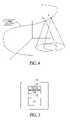
- FIG. 4illustrates movement of a camera across a three-dimensional scene
- FIG. 5illustrates an inertial guidance system which can be used in the imaging systems shown in FIGS. 1-3 ;
- FIGS. 6-8illustrate various embodiments of Kalman filtering to achieve accurate position and trajectory information according to the present invention
- FIG. 9illustrates a detector and a timing circuit according to the present invention.
- FIG. 10illustrates an interpolator which can be used in the timing circuit of FIG. 9 .
- FIG. 1A representative system 100 for creating a high resolution three-dimensional image of a scene of interest 101 is shown in FIG. 1 .
- a pulsed light source 102typically a laser, is directed toward target scene 101 .
- a portion of the lightis reflected back from the scene.
- An array of detectors 104receives the light from portions of the scene. The distance from the system to the portion of the scene 101 in the field of view of a single detector is determined by the time required for the light to illuminate that portion and then return to the detectors 104 .
- imaging system 100includes a laser 102 , optics 103 , a detector array 104 , a timer circuit 106 , a processor 108 , storage 110 and a display 112 .
- system 100also includes a resonator/attenuator 114 used to calibrate system 100 and an inertial guidance system 116 used to establish the position of imaging system 100 .
- System 100measures the round trip time for a reflected laser pulse from one or more targets for each of a two-dimensional array of pixels, providing an image with millimeter range accuracy and resolution.
- system 100includes a scanner mechanism (not shown) for directing light from laser 102 to a specific point or scene of interest.
- imaging system 100is a scannerless system that is pointed at particular scenes of interest.
- system 100includes a pulse generator 130 connected to a laser 132 .
- the pulse generatorissues an electrical pulse which is turned into an optical pulse by laser 132 . If the time from generation of the electrical pulse to the optical pulse is repeatable, transmit time can be determined from generation of the electrical pulse by pulse generator 130 . If not, transmit time can be determined based on generation of the optical pulse by laser 132 .
- System 100measures the round trip time for reflected laser pulse from one or more targets for each of a one or two-dimensional array of pixels, providing an image with millimeter range accuracy and resolution.
- optics 134 and detector 136receive light reflected from object 101 .
- Each detector 136is connected to a timing circuit 138 .
- each timing circuit 138includes a plurality of interpolators.
- An optical pulseis transmitted toward object 101 so that a portion of the optical pulse is reflected from the object as a reflected pulse.
- the reflected pulsepasses through optics 134 and falls on detector 136 .
- the time for the optical pulse to bounce off object 101 and arrive at one or more of the detectors 136is used to determine range to object 101 .
- detecting arrival of the reflected pulseincludes integrating the reflected pulse over a predetermined interval of time to determine a reflected pulse characteristic and recording a value representative of when the reflected pulse arrived at detector 136 . Range is then calculated as a function of the transmit time, the receive time and the reflected pulse characteristic.
- system 100includes detector 140 and timing circuit 142 . Detector 140 and timing circuit 142 can be used to determine transmit time for the optical pulse.
- light from the outgoing optical pulseis partially reflected to detector 136 by mirror 118 .
- Detectors 136 and timing circuits 138 and their methods of operationare described in U.S. patent application Ser. No. 10/886,073, entitled “System and Method for Determining Range in 3D Imaging Systems”, the descriptions of which is incorporated herein by reference.
- detector arrays 104 and 136 and timer arrays 106 and 138are implemented as a hybrid of two chips, an array of detectors connected to an array of processing electronics unit cells. Each detector on one chip is connected to its own processing-electronics unit cell on the other chip. This defines one voxel in the image. Each processing-electronics unit cell on the array contains an identical and unique integrated circuit which can store one or more reflected-pulse transit times and either the associated reflected-pulse energy or peak amplitude. Transit-time and pulse amplitude information for all pixels is read out preferably between laser pulses.
- the array of detectors and their associated processing-electronics unit cellsare distributed throughout an integrated circuit. While this has the disadvantage of providing a smaller proportion of surface area to collect photons, it can be produced much more economically since the two chips do not need to be mated.
- An array lidarproduces range images at a high rate—anywhere from several frames per second to several thousand frames per second. Depending on the motion of the lidar, sequential images will have some level of overlap, and this overlap can be used to align them. An example of overlap is shown in FIG. 4 .
- ICPIterative Closest Point
- the ICP algorithmhas been extended to multiple range images; a good example, introduced by Pulli in his article entitled “Multiview Registration for Large Data Sets,” Proceedings of Second International Conference on 3 D Digital Imaging and Modeling (3DIM'99), Ottawa, Canada, October 1999, is to do a series of pairwise registrations, and at the end subsample the overlap of each pair. Then a global algorithm is used to find the set of transformations that minimizes the squared distances between these subsampled points.
- Inertial guidance systemsenable the computation of position and orientation over time—the system trajectory.
- a modern inertial navigation systemgenerally includes inertial sensors such as gyroscopes and accelerometers that are rigidly attached to the system.
- the gyroscopesmeasure angular rotation
- the accelerometersmeasure acceleration in an inertial reference frame.
- the alignment of images from an array lidarrequires an initial estimate of their position in space. This estimate will depend on the motion of the lidar equipment and the orientation of its field of view. While this can be estimated with an inertial guidance system, the accuracy of the inertial guidance and the alignment algorithm can be enhanced if the position and orientation of both are estimated simultaneously.
- inertial guidance system 116includes an inertial measurement unit 120 .
- Inertial measurement unit 120provides approximate estimates of the relative motion of a lidar array between acquisitions of sequential frames; this provides a good initial estimate of the relative position and orientation of those images.
- inertial guidance system 116includes a GPS receiver 122 ; GPS receiver 122 improves the accuracy of the inertial system, and working together they can produce better trajectory estimates than either alone.
- a level and/or a compasscan facilitate initialization of inertial guidance system 116 .
- Additional sensorscan help resolve the initial position values.
- Extremely expensive sensorssuch as inertial navigation systems, can help resolve the numerical stability problems.
- similar resultscan be obtainable with very inexpensive sensors coupled with an advanced position estimation algorithm; they provide results similar in character and benefits to the more expensive inertial systems.
- a set of gyrosto determine angular velocity
- a set of accelerometersto determine linear acceleration
- a GPS radioto determine absolute position. While the gyros and accelerometers work well over a short period of time, they can drift over a longer period of time. In contrast, the GPS receiver does not give good results over a short period of time, but it is very stable over a longer period of time.
- the information from the three sets of sensorsis integrated with a Kalman filter estimation algorithm, which makes the best use of all three sensor types in producing a combined overall position estimate at each point in time.
- ICPiterated closest point algorithm
- system 100combines the information from cloud registration 124 with that from an inertial measurement unit 120 using a Kalman filter 126 .
- a Kalman filteris used to estimate some n-dimensional quantity x k at each of several times based on 1-dimensional measurements z k .
- Inertial measurement unit 120provides initial estimates for a pairwise registration between sequential frames.
- a global image registration algorithmcan be used to place all the data in a common reference frame. The algorithm for computing the inertial estimates and the global registration can cooperate to provide better accuracy than either alone.
- a GPS receiver 122provides data that coupled with the inertial data and the registration results provides better overall accuracy. Such an approach is shown in FIG. 7 .
- Kalman filter 128 associated with GPS receiver 122is integrated with the registration and inertial estimator of Kalman filter 126 , to provide an efficient overall estimator in real time.
- the Kalman filtercan additionally provide estimates of accelerometer bias and scale factor, and gyroscope bias and scale factor.
- the quantity x to be estimated by the Kalman filteris the nine-dimensional vector consisting of the errors in position, velocity, and attitude (i.e. the deviation of the actual path from the preliminary estimate), measured in the reference coordinate system.
- the attitude erroris linearized in the usual axis-times-angle manner.
- the matrix ⁇is determined from the equations of motion.
- Fbe the 9 ⁇ 9 matrix written with 3 ⁇ 3 blocks:
- the covariance matrix Q for the process noisehas been determined as part of the calibration process.
- This modelcan also be extended, as in Rogers, ch. 12, to estimate specific sources of bias in the instruments in addition to errors in the path.
- ⁇ ⁇ ( z )1 ( 2 ⁇ ⁇ ) n ⁇ det ⁇ ( P ) ⁇ e - 1 2 ⁇ z ′ ⁇ P - 1 ⁇ z ,
- this functionwould give a Gaussian probability distribution on the (linearized) space of transformations, and the covariance matrix would be the inverse of the Hessian of ⁇ .
- fan estimate of the average square distance between the two scans in their overlapping region.
- the output of the cloud registration processis a transformation (position and orientation).
- a transformationposition and orientation
- Kalman filteringuses the system and measurement models to find an optimal estimate for each position based on the data collected at that time and before, but we want to estimate each position using all data, including that collected afterward.
- a basic Kalman filteruses the system and measurement models to find an optimal estimate for each position based on the data collected at that time and before, but we want to estimate each position using all data, including that collected afterward.
- inertial dataIn the most general case, we will have inertial data, global registration data, and global positioning data.
- P k r ( ⁇ )is positive definite, and describes the uncertainty in our estimate of the position, relative to the previous estimate.
- the registrationwill be over-constrained.
- the output of the global registrationwill be an estimate of the absolute position error z k of each scan, along with an estimated covariance R k .
- the quantity to be minimizedis as follows. For each scan, the GPS gives a measured position z i with covariance matrix R i .
- the INUgives a relative transformation T i 1 between the i and (i+1) positions with covariance matrix Q i 1 , and the registration gives relative transformations T ij R with covariance matrix Q ij R for some subset S of ordered pairs (i, j).
- Kalman filter implementationincludes calibration and determining initial conditions.
- the dynamic parametershave to be carefully calibrated to give a good estimate of current position based on the raw data from the accelerometer and gyroscope. This will need to take into account cross-axis terms, coupling between the two, etc. We also need to determine in advance the relation between the coordinate systems inherent in the raw data from the inertial unit and the raw data of a scan; the formulas above assume that these have already been reconciled. One can also add terms to the Kalman filter state vector to make real-time estimates of bias and drift in the instruments.
- a level and/or a compasswill aid in estimating the initial pose of the system, and in establishing agreement between the coordinate systems of the different sensors.
- a core principle of any pulsed lidar systemis to measure the time between when a pulse is emitted and when a reflected pulse is received.
- Lighttravels at the speed of light, c m , for the medium in which it travels.
- the fundamental problem in a millimeter resolution pulsed lidaris to measure time to an accuracy of a few picoseconds.
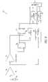
- a timing circuit 138 which can be used in system 100 of FIGS. 1-3is shown in FIG. 9 .
- the returning lightis detected by detector 150 and converted to an electrical signal.
- the signalis amplified by transimpedance amplifier (TIA) 152 , and then converted into a signal appropriate to trigger a flip-flop by discriminator 154 .
- the output of flip-flop 156goes high when a first pulse is detected, and the output of flip-flop 158 goes high only when a second pulse is detected.
- the time of arrival of the two pulsesis converted to a digital signal by time converters 160 and 162 and read out through multiplexer 168 .
- timing circuit 138includes gated integrators 164 and 166 .
- the amplitude of the two pulsesis determined by integrating the signal from slightly before the pulse starts until shortly after the pulse ends.
- a peak detectoris employed rather than a gated integrator. While simpler to implement, this is likely to provide poorer performance as the peak of a pulse is not a good monotonic indicator of pulse energy, particularly when the detector is operating in a non-linear region.
- the measurement of pulse intensityis critical in making accurate range measurements when the associated timing measurements are made between times at which the pulses exceed a threshold and the required precision is significantly smaller than the pulse rise time.
- the thresholdis exceeded sooner, and this leads to an apparently shorter distance (ranging error).
- An accurate measure of pulse intensitysuch as provided by a gated integrator, provides an effective means of compensating for this apparent error in range measurement.
- a peak detectorcan be used to estimate pulse intensity; however this provides much less accurate range compensation—particularly when the detector is operating in saturation.
- the gated integratorcan be triggered in advance of the arrival of the received pulse by the introduction of a delay line of a few nanoseconds.
- the introduction of such a delay line at each pixelwould be prohibitive.
- two gated integrators 164 and 166are employed alternately, and the integration on each is over a time that is at least as long as the longest pulse that will be observed.
- the alternation between integratorsis stopped, and the last integrated pulse is utilized to compensate the range measurement.
- reflected pulsesare 1-20 ns in length when they reach detector 136 .
- a method of determining the transit time for an optical pulsewill be described next.
- the simplest approach to measuring time interval between two pulsesis to enable a counter when the first pulse arrives, stop the counter when the second pulse arrives, and record the number of counts.
- the number of counts times the clock periodwill be the time.
- the basic problem with thisis that in order to have a resolution of 1 mm, the clock frequency would have to be approximately 200 GHz. This is neither economic nor practical for a large array of sensors.
- Timing circuit 138stretches the time interval two or more times, so that a more modest clock frequency can be utilized to achieve the required accuracy.
- the fundamental concept of this interpolatoris to create a linear charging ramp on a capacitor when the first pulse arrives, begin discharging this capacitor at a different rate after a fixed number of master clock pulses, and enable a counter on the master clock pulses until the capacitor arrives at its original state. Implementations of this process have been previously called Nutt interpolators.
- each time converter 160 and 162includes at least one interpolator.
- An interpolatormeasures the time between an asynchronous event and a subsequent master clock pulse.
- each interpolatorincludes an interpolator circuit which charges a capacitor at a different rate than it discharges.
- An example interpolator circuit 180is shown in FIG. 10 .
- integrating capacitor 182is held at a high level by upper current source 184 .
- flip-flop 186waits for a pulse and the coarse counter is enabled.
- flip-flop 186is clocked, and that in turn causes integrating capacitor 180 to be discharged by a lower current source 185 at a high rate, and the fine counter is enabled.
- the transition of flip-flop 188propagates through the synchronizing flip-flops 188 and 190 , integrating capacitor 182 is then charged again by upper current source 184 .
- the output of comparator 192shows that the integrating capacitor has returned to its original level, the fine counter is disabled.
- two or more separate interpolator circuits 180are cascaded, with the discharge of one triggered when the previous capacitor has returned to a threshold value.
- an interpolatorincludes five or six cascaded interpolator circuits 180 ; the discharge of one interpolator circuit 180 is triggered when the previous capacitor has returned to a threshold value.
- the clockoperates at 100 Mhz and the rate of charging for each capacitor is 8-16 (corresponding to 3 or 4 bits) times the rate of discharging. If the rate of charging is 8 times that of discharging, such an embodiment leads to a total interpolation of 8 ⁇ 5 or 32,768 times the rate of discharging.
- Interpolation capacitorsmay, for instance, be on the order of 8-20 fF, with the charging/discharging currents about 200-800 nA.
- An alternative approachis to provide a single slope measurement of the timing interpolation, saving the voltage on the interpolator until after all the pixel measurements are performed. At that point the interpolated value can be multiplexed off the chip with an analog multiplexer, rather than a digital multiplexer as provided in the dual slope implementation. These values would then be converted by an off-chip analog-to-digital converter.
- a capacitorWhen a pulse is detected, a capacitor will be charged at a fixed rate until a subsequent transition of the master clock. The value of the voltage on the capacitor will be proportional to the time between the pulse and this clock edge.
- the multiplexerin this case, will transmit an analog voltage off chip.
- the value of the intensity measurementcan be either digitized at the pixel and multiplexed as a digital value or it can be multiplexed as an analog voltage to an off-chip analog-to-digital converter. Nearly identical circuitry will suffice to digitize the intensity as was used to measure the interpolated voltage—a counter will determine how long it takes to reduce the stored voltage to an original value. When the dual slope time-to-digital interpolator is utilized, it is preferable to digitize the intensity measurement at the pixel as much of the timing interpolator circuitry can be reused.
- system 100also may include a resonator/attenuator 114 used to calibrate system 100 .
- a resonator/attenuator 114used to calibrate system 100 .
- One impediment to making highly accurate measurements with an individual pixelis the variation of circuit properties that can occur during operation, including variations of laser pulse properties, environmental conditions and aging. Additionally, within an array individual pixels may behave differently, and the variation of their behavior may not track with environmental conditions or time. Also, when the detectors operate in saturation, the intensity measurement may not be linear. Consequently it is important to incorporate components which can allow the system to compensate for these behaviors across the array.
- resonator/attenuator 114is added to characterize the properties of individual pixels and their variation as a function of pulse properties, environmental conditions, and aging; and the variation of behavior within the array.
- the principle function of this assemblyis to provide a known range of signals to the receiver, essentially simulating the circumstances the receiver would experience when presented with a test object but within the confines of the instrument.
- the instrumentWhen in calibration mode, the instrument will be presented with a sequence of pulses from the resonator/attenuator 114 , and measured results from this will be subsequently used to adjust the measurements taken from real objects.
- Resonator/attenuator 114imposes the same pulse delay pattern across the detector array every time since the geometry of the components will be unchanged.
- a single factory calibration of the apparent differences across the arraycan be supplemented with the apparent differences at the moment the array uniformity is being field evaluated, and the sum of these corrections can be applied to every pixel when applied to real objects.
- timing interpolatorsare designed to provide an accurate, linear measure of the elapsed time between asynchronous events and system clock pulses
- real circuitscan only provide an approximation. The difference can become exceedingly important when attempting to make measurements with picosecond precision, and also when the interpolation ratios are large.
- t k eT N ⁇ ( ⁇ i ⁇ k ⁇ ⁇ n i + n k 2 ) .
- a two step processis applied to obtain enhanced range information on inclined surfaces While the ranges to inclined surfaces will be underestimated, the normal to these surfaces will be well approximated if adjacent samples are on the same region. Therefore, a good approximation of the surface normal can be obtained uncorrected data. Then, in a second step, the range to the center of the laser spot can be determined by increasing the first range estimate in accordance with this normal estimate.
- o(x,y)represent the range distribution associated with an object
- r(x,y)represent the range distribution associated with a blurred image of that object.
- the blur the image has been subjected tois a linear, space-invariant transformation, describable by a known space-invariant point-spread function s(x,y).
- n(x,y)is the noise associated with the detection process. If the power spectral densities of the object and the noise are represented by ⁇ o ( ⁇ X , ⁇ Y ) and ⁇ n ( ⁇ X , ⁇ Y ), then the transfer function of the optimum restoration filter is given by:
- H ⁇ ( f X , f Y )S * ⁇ ( f X , f Y ) ⁇ S ⁇ ( f X , f Y ) ⁇ 2 + ⁇ n ⁇ ( f X , f Y ) ⁇ o ⁇ ( f X , f Y )
- the present inventionprovides a system and method for three dimensional imaging of objects in a three-dimensional scene.
- the imaging systemincludes a light source, a detector array, a timing circuit, an inertial guidance system and a processor.
- the light sourcegenerates an optical pulse and projects the optical pulse on an object so that it is reflected as a reflected pulse.
- the detector arrayincludes a plurality of detectors, wherein the detectors are oriented to receive the reflected pulse.
- the timing circuitis connected to the detector array. It determines when the reflected pulse reached detectors on the detector array.
- the inertial guidance systemmeasures angular velocity and acceleration.
- the processoris connected to the timing circuit and the inertial guidance system. The processor forms a composite image of the three-dimensional scene as a function of camera position and range to objects in the three-dimensional scene.
- a camera operatorscans a room by pointing the camera to different spots in the rooms.
- the inertial guidance systemcontinuously measures movement of the camera relative to an initial position and forms a range image for two or more of the spots where the camera is pointed.
- An estimated camera motionis determined consistent with measurements from the inertial guidance system and a composite image is formed from the two or more range images, wherein forming a composite image includes determining alignment of the two or more range images as a function of the estimated camera motion.
- computerand “processor” are defined to include any digital or analog data processing unit. Examples include any personal computer, workstation, set top box, mainframe, server, supercomputer, laptop or personal digital assistant capable of embodying the inventions described herein.
- Examples of articles comprising computer readable mediaare floppy disks, hard drives, CD-ROM or DVD media or any other read-write or read-only memory device.
Landscapes
- Engineering & Computer Science (AREA)
- Radar, Positioning & Navigation (AREA)
- Remote Sensing (AREA)
- Physics & Mathematics (AREA)
- General Physics & Mathematics (AREA)
- Automation & Control Theory (AREA)
- Multimedia (AREA)
- Computer Networks & Wireless Communication (AREA)
- Electromagnetism (AREA)
- Optical Radar Systems And Details Thereof (AREA)
- Length Measuring Devices By Optical Means (AREA)
- Studio Devices (AREA)
- Navigation (AREA)
- Analysing Materials By The Use Of Radiation (AREA)
Abstract
Description
- 1) We assume that we are given an initial transformation T01such that the scans S0and T01S1are approximately aligned, and we wish to refine this transformation to find the correct alignment.
- 2) For each point Pjin S0we find the point Qjin a surface defined by S1with the minimal distance between Pjand Ti1Qj, and similarly for each point Qj in S1 we find the point Pjin a surface defined by S0 with minimal distance between Pjand Ti1Qj.
- 3) We find the transformation Ti+11that minimizes the sum of the square distances between Ti+11Qjand Pj.
- 4) Repeat steps 2 and 3 until the distance between the two surfaces ƒ=Σjwj|Pj−Qj|2, is minimized.
- 1. A system or plant model. This consists of an n×n matrix Φkdescribing the expected transition from state xkto state xk+1and an n-dimensional random variable wkmodeling the measurement noise. Thus, the dynamics of the system are given by
xk+1=Φk+1xk+wk- The covariance of wk, which is the expected value Ewkwkt
 is denoted Qk.
- The covariance of wk, which is the expected value E
- 2. A measurement model. This consists of 1×n matrix Hkdescribing the measurement, and an 1-dimensional random variable vkmodeling the measurement noise, so we have
zk+1=Hkxk+vk- The covariance of vk, Evkvktis denoted Rk.
- The covariance of vk, E
- 1. A system or plant model. This consists of an n×n matrix Φkdescribing the expected transition from state xkto state xk+1and an n-dimensional random variable wkmodeling the measurement noise. Thus, the dynamics of the system are given by


Φ=exp(F·δt)≈I+F·δt+F2(δt)2/2.
E
of second partial derivatives with respect to the 6 parameters pi(translations and rotations). The output of the cloud registration process is a transformation (position and orientation). In the simplest case, for each successive pair of scans, we run a pairwise cloud registration using the inertial data to give an initial transformation, and getting as output the 6-vector describing the translation and rotation from this initial transformation to the final transformation. We can treat this transformation as a measurement, and estimate its covariance as a scalar multiple of M−1, the inverse of the Hessian matrix.
- If there are registrations between non-consecutive scans in addition to those between consecutive ones, we can use the global registration to give an estimate of absolute positions for each scan. First do all necessary pairwise registrations, using the inertial data to determine which ones overlap and to create initial estimates. A global registration results in the computation of a covariance with respect to all parameters based on the composite objective function. The results of the global registration can be used as measurement inputs in the Kalman filter. Finally, estimate each position using the Rauch-Tung-Striebel two-pass smoother, which essentially runs a Kalman filter forward and then backward in time. This should not add much time to the overall process, since the global registration is much less computationally intensive than the pairwise ones.
- If we also collect global positioning system (GPS) data from the camera and there is registration information only between consecutive scans, we can use all the information in a two-step process. First, we combine the registration information with the inertial information at each step (as in the simple case without GPS information) into a single estimate for the position (and its covariance) relative to the previous step. Then, combine this with GPS information in the standard way. In other words, the inertial data and the registration are both part of the dynamic model, and the GPS data serves as the measurement model.
{circumflex over (x)}k(−)=Φk−1{circumflex over (x)}k−1(+)
Pk(−)=Φk−1Pk−1(+)Φk−1t+Qk−1
Pkr(−)=Pk(−)−Pk−1(+)
Then we can use a relative version of the Kalman filter equations to find the optimal estimate {circumflex over (x)}k(+) of the state. Let
Kk=Pkr(−)Ht(HPkr(−)Ht+Rkr)−1
{circumflex over (x)}k(+)={circumflex over (x)}k(−)+Kk[zk−H{circumflex over (x)}k(−)],
Pkr(+)=[I−KkH]Pkr(−)
Pk(+)Pk−1(+)+Pkr(+).
{circumflex over (x)}k(−)=φ(k){circumflex over (x)}k−1(+)
Pk(−)Φk−1Pk−1(+)Φk−1t+Qk−1
Kk=Pk(−)Ht[HPk(−)Ht+Rk]−1
{circumflex over (x)}k(+)={circumflex over (x)}k(−)+Kk[zk−H{circumflex over (x)}k(−)]
Pk(+)=[I−KkH]Pk(−)
Ak=Pk(+)ΦktPk+1−1(−)
{circumflex over (x)}[s]k={circumflex over (x)}k(+)+Ak({circumflex over (x)}[s]k+1−{circumflex over (x)}k+1(−))
P[s]k=Pk(+)+Ak(P[s]k+1−Pk+1(−))Akt
Ti1Ti+1−1Ti,
TijRTj−1Ti.
then an approximate measure of the proportion of measurements landing in the kthtime slot is nk/N. There are a few similar and reasonable ways to correct future measurements on the basis of these observations, but a sensible (and successful) approach is to assign each new interpolated value the time associated with the center of the time slot during which it occurs. Accordingly, a sensible set of approximate correction factors can be estimated as
r(x,y)=∫∫o(ξ,η)s(x−ξ,y−η)dξdη
F{r(x,y)}=F{s(x,y){circle around (x)}o(x,y)}=S(ƒX,ƒY)O(ƒX,ƒY)
Ô(ƒX,ƒY)=H(ƒX,ƒY)R(ƒX,ƒY),
r(x,y)=o(x,y){circumflex over (x)}s(x,y)+n(x,y)
Claims (49)
Priority Applications (6)
| Application Number | Priority Date | Filing Date | Title |
|---|---|---|---|
| US10/886,079US7697748B2 (en) | 2004-07-06 | 2004-07-06 | Method and apparatus for high resolution 3D imaging as a function of camera position, camera trajectory and range |
| DE602005013962TDE602005013962D1 (en) | 2004-07-06 | 2005-07-06 | PROCESS FOR HIGH RESOLUTION 3D IMAGING |
| EP05800109AEP1769266B1 (en) | 2004-07-06 | 2005-07-06 | Method and apparatus for high resolution 3d imaging |
| PCT/US2005/023867WO2006014445A1 (en) | 2004-07-06 | 2005-07-06 | Method and apparatus for high resolution 3d imaging |
| AT05800109TATE428939T1 (en) | 2004-07-06 | 2005-07-06 | METHOD FOR HIGH-RESOLUTION 3D IMAGING |
| US12/701,371US7991222B2 (en) | 2004-07-06 | 2010-02-05 | Method and apparatus for high resolution 3D imaging as a function of camera position, camera trajectory and range |
Applications Claiming Priority (1)
| Application Number | Priority Date | Filing Date | Title |
|---|---|---|---|
| US10/886,079US7697748B2 (en) | 2004-07-06 | 2004-07-06 | Method and apparatus for high resolution 3D imaging as a function of camera position, camera trajectory and range |
Related Child Applications (1)
| Application Number | Title | Priority Date | Filing Date |
|---|---|---|---|
| US12/701,371ContinuationUS7991222B2 (en) | 2004-07-06 | 2010-02-05 | Method and apparatus for high resolution 3D imaging as a function of camera position, camera trajectory and range |
Publications (2)
| Publication Number | Publication Date |
|---|---|
| US20060006309A1 US20060006309A1 (en) | 2006-01-12 |
| US7697748B2true US7697748B2 (en) | 2010-04-13 |
Family
ID=35474714
Family Applications (2)
| Application Number | Title | Priority Date | Filing Date |
|---|---|---|---|
| US10/886,079Active2027-02-11US7697748B2 (en) | 2004-07-06 | 2004-07-06 | Method and apparatus for high resolution 3D imaging as a function of camera position, camera trajectory and range |
| US12/701,371Expired - LifetimeUS7991222B2 (en) | 2004-07-06 | 2010-02-05 | Method and apparatus for high resolution 3D imaging as a function of camera position, camera trajectory and range |
Family Applications After (1)
| Application Number | Title | Priority Date | Filing Date |
|---|---|---|---|
| US12/701,371Expired - LifetimeUS7991222B2 (en) | 2004-07-06 | 2010-02-05 | Method and apparatus for high resolution 3D imaging as a function of camera position, camera trajectory and range |
Country Status (5)
| Country | Link |
|---|---|
| US (2) | US7697748B2 (en) |
| EP (1) | EP1769266B1 (en) |
| AT (1) | ATE428939T1 (en) |
| DE (1) | DE602005013962D1 (en) |
| WO (1) | WO2006014445A1 (en) |
Cited By (49)
| Publication number | Priority date | Publication date | Assignee | Title |
|---|---|---|---|---|
| US20090029299A1 (en)* | 2007-07-26 | 2009-01-29 | Siemens Aktiengesellschaft | Method for the selective safety-related monitoring of entrained-flow gasification reactors |
| US20090076758A1 (en)* | 2004-07-06 | 2009-03-19 | Dimsdale Engineering, Llc. | System and method for determining range in 3d imaging systems |
| US20100188504A1 (en)* | 2004-07-06 | 2010-07-29 | Dimsdale Engineering, Llc | Method and apparatus for high resolution 3d imaging as a function of camera position, camera trajectory and range |
| US8207484B1 (en)* | 2007-12-06 | 2012-06-26 | Voxtel, Inc. | Streak image sensor and method of operating |
| US8401242B2 (en) | 2011-01-31 | 2013-03-19 | Microsoft Corporation | Real-time camera tracking using depth maps |
| US8401225B2 (en) | 2011-01-31 | 2013-03-19 | Microsoft Corporation | Moving object segmentation using depth images |
| US8570320B2 (en) | 2011-01-31 | 2013-10-29 | Microsoft Corporation | Using a three-dimensional environment model in gameplay |
| US8577539B1 (en)* | 2010-01-27 | 2013-11-05 | The United States Of America As Represented By The Secretary Of The Air Force | Coded aperture aided navigation and geolocation systems |
| US8587583B2 (en) | 2011-01-31 | 2013-11-19 | Microsoft Corporation | Three-dimensional environment reconstruction |
| US8711206B2 (en) | 2011-01-31 | 2014-04-29 | Microsoft Corporation | Mobile camera localization using depth maps |
| US20140309960A1 (en)* | 2013-04-12 | 2014-10-16 | p3d systems GmbH | Method for Calibrating a Detection Device, and Detection Device |
| US8913784B2 (en) | 2011-08-29 | 2014-12-16 | Raytheon Company | Noise reduction in light detection and ranging based imaging |
| US8942917B2 (en) | 2011-02-14 | 2015-01-27 | Microsoft Corporation | Change invariant scene recognition by an agent |
| US8958654B1 (en)* | 2001-04-25 | 2015-02-17 | Lockheed Martin Corporation | Method and apparatus for enhancing three-dimensional imagery data |
| US8997362B2 (en) | 2012-07-17 | 2015-04-07 | Faro Technologies, Inc. | Portable articulated arm coordinate measuring machine with optical communications bus |
| US20150097951A1 (en)* | 2013-07-17 | 2015-04-09 | Geoffrey Louis Barrows | Apparatus for Vision in Low Light Environments |
| US9009000B2 (en) | 2010-01-20 | 2015-04-14 | Faro Technologies, Inc. | Method for evaluating mounting stability of articulated arm coordinate measurement machine using inclinometers |
| US9074883B2 (en) | 2009-03-25 | 2015-07-07 | Faro Technologies, Inc. | Device for optically scanning and measuring an environment |
| US9113023B2 (en) | 2009-11-20 | 2015-08-18 | Faro Technologies, Inc. | Three-dimensional scanner with spectroscopic energy detector |
| US9134339B2 (en) | 2013-09-24 | 2015-09-15 | Faro Technologies, Inc. | Directed registration of three-dimensional scan measurements using a sensor unit |
| US9163922B2 (en) | 2010-01-20 | 2015-10-20 | Faro Technologies, Inc. | Coordinate measurement machine with distance meter and camera to determine dimensions within camera images |
| US9168654B2 (en) | 2010-11-16 | 2015-10-27 | Faro Technologies, Inc. | Coordinate measuring machines with dual layer arm |
| US9210288B2 (en) | 2009-11-20 | 2015-12-08 | Faro Technologies, Inc. | Three-dimensional scanner with dichroic beam splitters to capture a variety of signals |
| USRE45854E1 (en) | 2006-07-03 | 2016-01-19 | Faro Technologies, Inc. | Method and an apparatus for capturing three-dimensional data of an area of space |
| US9247238B2 (en) | 2011-01-31 | 2016-01-26 | Microsoft Technology Licensing, Llc | Reducing interference between multiple infra-red depth cameras |
| US9329271B2 (en) | 2010-05-10 | 2016-05-03 | Faro Technologies, Inc. | Method for optically scanning and measuring an environment |
| US9372265B2 (en) | 2012-10-05 | 2016-06-21 | Faro Technologies, Inc. | Intermediate two-dimensional scanning with a three-dimensional scanner to speed registration |
| US9417056B2 (en) | 2012-01-25 | 2016-08-16 | Faro Technologies, Inc. | Device for optically scanning and measuring an environment |
| US9417316B2 (en) | 2009-11-20 | 2016-08-16 | Faro Technologies, Inc. | Device for optically scanning and measuring an environment |
| US9470520B2 (en) | 2013-03-14 | 2016-10-18 | Apparate International C.V. | LiDAR scanner |
| US9513107B2 (en) | 2012-10-05 | 2016-12-06 | Faro Technologies, Inc. | Registration calculation between three-dimensional (3D) scans based on two-dimensional (2D) scan data from a 3D scanner |
| US9529083B2 (en) | 2009-11-20 | 2016-12-27 | Faro Technologies, Inc. | Three-dimensional scanner with enhanced spectroscopic energy detector |
| US9551575B2 (en) | 2009-03-25 | 2017-01-24 | Faro Technologies, Inc. | Laser scanner having a multi-color light source and real-time color receiver |
| US9607239B2 (en) | 2010-01-20 | 2017-03-28 | Faro Technologies, Inc. | Articulated arm coordinate measurement machine having a 2D camera and method of obtaining 3D representations |
| US9628775B2 (en) | 2010-01-20 | 2017-04-18 | Faro Technologies, Inc. | Articulated arm coordinate measurement machine having a 2D camera and method of obtaining 3D representations |
| US9772399B2 (en) | 2013-11-22 | 2017-09-26 | Uber Technologies, Inc. | LiDAR scanner calibration |
| US9823351B2 (en) | 2012-12-18 | 2017-11-21 | Uber Technologies, Inc. | Multi-clad fiber based optical apparatus and methods for light detection and ranging sensors |
| US10067231B2 (en) | 2012-10-05 | 2018-09-04 | Faro Technologies, Inc. | Registration calculation of three-dimensional scanner data performed between scans based on measurements by two-dimensional scanner |
| US10094916B1 (en) | 2017-06-09 | 2018-10-09 | Waymo Llc | LIDAR optics alignment systems and methods |
| US10164776B1 (en) | 2013-03-14 | 2018-12-25 | goTenna Inc. | System and method for private and point-to-point communication between computing devices |
| US10210382B2 (en) | 2009-05-01 | 2019-02-19 | Microsoft Technology Licensing, Llc | Human body pose estimation |
| US10217294B2 (en) | 2008-05-07 | 2019-02-26 | Microsoft Technology Licensing, Llc | Procedural authoring |
| US10220172B2 (en) | 2015-11-25 | 2019-03-05 | Resmed Limited | Methods and systems for providing interface components for respiratory therapy |
| US10281259B2 (en) | 2010-01-20 | 2019-05-07 | Faro Technologies, Inc. | Articulated arm coordinate measurement machine that uses a 2D camera to determine 3D coordinates of smoothly continuous edge features |
| US10760913B2 (en) | 2018-02-21 | 2020-09-01 | Motorola Solutions, Inc. | Determining and reducing inertial navigation system drift |
| US11215711B2 (en) | 2012-12-28 | 2022-01-04 | Microsoft Technology Licensing, Llc | Using photometric stereo for 3D environment modeling |
| US20220130147A1 (en)* | 2019-02-22 | 2022-04-28 | Fogale Nanotech | Method and device for monitoring the environment of a robot |
| US11470303B1 (en) | 2010-06-24 | 2022-10-11 | Steven M. Hoffberg | Two dimensional to three dimensional moving image converter |
| US11710309B2 (en) | 2013-02-22 | 2023-07-25 | Microsoft Technology Licensing, Llc | Camera/object pose from predicted coordinates |
Families Citing this family (80)
| Publication number | Priority date | Publication date | Assignee | Title |
|---|---|---|---|---|
| US8417055B2 (en)* | 2007-03-05 | 2013-04-09 | DigitalOptics Corporation Europe Limited | Image processing method and apparatus |
| US8698924B2 (en) | 2007-03-05 | 2014-04-15 | DigitalOptics Corporation Europe Limited | Tone mapping for low-light video frame enhancement |
| US7639889B2 (en)* | 2004-11-10 | 2009-12-29 | Fotonation Ireland Ltd. | Method of notifying users regarding motion artifacts based on image analysis |
| US8180173B2 (en) | 2007-09-21 | 2012-05-15 | DigitalOptics Corporation Europe Limited | Flash artifact eye defect correction in blurred images using anisotropic blurring |
| US8264576B2 (en)* | 2007-03-05 | 2012-09-11 | DigitalOptics Corporation Europe Limited | RGBW sensor array |
| US7636486B2 (en) | 2004-11-10 | 2009-12-22 | Fotonation Ireland Ltd. | Method of determining PSF using multiple instances of a nominally similar scene |
| US8199222B2 (en)* | 2007-03-05 | 2012-06-12 | DigitalOptics Corporation Europe Limited | Low-light video frame enhancement |
| US9160897B2 (en)* | 2007-06-14 | 2015-10-13 | Fotonation Limited | Fast motion estimation method |
| US8989516B2 (en)* | 2007-09-18 | 2015-03-24 | Fotonation Limited | Image processing method and apparatus |
| WO2006121457A2 (en)* | 2004-08-18 | 2006-11-16 | Sarnoff Corporation | Method and apparatus for performing three-dimensional computer modeling |
| FR2876470B1 (en)* | 2004-10-12 | 2006-12-22 | Eastman Kodak Co | DISPLAY CONTROL METHOD USING PORTABLE IMAGE SENSOR EQUIPMENT |
| US7639888B2 (en)* | 2004-11-10 | 2009-12-29 | Fotonation Ireland Ltd. | Method and apparatus for initiating subsequent exposures based on determination of motion blurring artifacts |
| US7501981B2 (en)* | 2005-11-18 | 2009-03-10 | Texas Instruments Incorporated | Methods and apparatus to detect and correct integrity failures in satellite positioning system receivers |
| IES20070229A2 (en)* | 2006-06-05 | 2007-10-03 | Fotonation Vision Ltd | Image acquisition method and apparatus |
| US7773118B2 (en)* | 2007-03-25 | 2010-08-10 | Fotonation Vision Limited | Handheld article with movement discrimination |
| US20080309770A1 (en)* | 2007-06-18 | 2008-12-18 | Fotonation Vision Limited | Method and apparatus for simulating a camera panning effect |
| US8279411B2 (en)* | 2008-08-27 | 2012-10-02 | The Boeing Company | Systems and methods for reducing crosstalk in an avalanche photodiode detector array |
| US20100157280A1 (en)* | 2008-12-19 | 2010-06-24 | Ambercore Software Inc. | Method and system for aligning a line scan camera with a lidar scanner for real time data fusion in three dimensions |
| US20100204974A1 (en)* | 2009-02-09 | 2010-08-12 | Utah State University | Lidar-Assisted Stero Imager |
| US20110039573A1 (en)* | 2009-08-13 | 2011-02-17 | Qualcomm Incorporated | Accessing positional information for a mobile station using a data code label |
| DE102009055989B4 (en) | 2009-11-20 | 2017-02-16 | Faro Technologies, Inc. | Device for optically scanning and measuring an environment |
| US8855929B2 (en)* | 2010-01-18 | 2014-10-07 | Qualcomm Incorporated | Using object to align and calibrate inertial navigation system |
| US9229089B2 (en) | 2010-06-10 | 2016-01-05 | Qualcomm Incorporated | Acquisition of navigation assistance information for a mobile station |
| US9041796B2 (en)* | 2010-08-01 | 2015-05-26 | Francis Ruben Malka | Method, tool, and device for determining the coordinates of points on a surface by means of an accelerometer and a camera |
| CN101923161B (en)* | 2010-08-30 | 2012-12-05 | 哈尔滨工业大学 | Device and method for detecting co-optical system and co-detector glimmer passive and laser active compound imaging |
| CN102565808B (en)* | 2010-12-17 | 2015-10-21 | 上海无线电设备研究所 | A kind of implementation method of sparse array high-speed three-dimensional imaging lidar |
| FR2969819A1 (en)* | 2010-12-22 | 2012-06-29 | St Microelectronics Grenoble 2 | THREE DIMENSIONAL IMAGE SENSOR |
| CN102175211B (en)* | 2010-12-24 | 2012-08-22 | 北京控制工程研究所 | Barrier position determining method based on lattice structured light |
| US9395182B1 (en) | 2011-03-03 | 2016-07-19 | The Boeing Company | Methods and systems for reducing crosstalk in avalanche photodiode detector arrays |
| US11933899B2 (en) | 2011-06-30 | 2024-03-19 | The Regents Of The University Of Colorado | Remote measurement of shallow depths in semi-transparent media |
| US10684362B2 (en)* | 2011-06-30 | 2020-06-16 | The Regents Of The University Of Colorado | Remote measurement of shallow depths in semi-transparent media |
| US11313678B2 (en) | 2011-06-30 | 2022-04-26 | The Regents Of The University Of Colorado | Remote measurement of shallow depths in semi-transparent media |
| US11231502B2 (en) | 2011-06-30 | 2022-01-25 | The Regents Of The University Of Colorado | Remote measurement of shallow depths in semi-transparent media |
| US9115990B2 (en) | 2012-01-18 | 2015-08-25 | Harris Corporation | Geospatial and image data collection system including image sensor for capturing 3D geospatial data and 2D image data and related methods |
| WO2013142807A1 (en)* | 2012-03-22 | 2013-09-26 | Northeastern University | Conformal and configurable millimeter-wave integrated array radar in a compact package |
| DE102012107544B3 (en) | 2012-08-17 | 2013-05-23 | Faro Technologies, Inc. | Optical scanning device i.e. laser scanner, for evaluating environment, has planetary gears driven by motor over vertical motor shaft and rotating measuring head relative to foot, where motor shaft is arranged coaxial to vertical axle |
| US9891321B2 (en) | 2013-01-21 | 2018-02-13 | Vricon Systems Aktiebolag | Method and arrangement for developing a three dimensional model of an environment |
| EP2946367B1 (en)* | 2013-01-21 | 2018-03-07 | Vricon Systems Aktiebolag | A method and an apparatus for estimating values for a set of parameters of an imaging system |
| GB201301281D0 (en) | 2013-01-24 | 2013-03-06 | Isis Innovation | A Method of detecting structural parts of a scene |
| GB2510891A (en)* | 2013-02-18 | 2014-08-20 | St Microelectronics Res & Dev | Apparatus |
| GB201303076D0 (en) | 2013-02-21 | 2013-04-10 | Isis Innovation | Generation of 3D models of an environment |
| US20140368504A1 (en)* | 2013-06-12 | 2014-12-18 | Microsoft Corporation | Scalable volumetric 3d reconstruction |
| US9523772B2 (en) | 2013-06-14 | 2016-12-20 | Microsoft Technology Licensing, Llc | Object removal using lidar-based classification |
| US9110163B2 (en) | 2013-06-14 | 2015-08-18 | Microsoft Technology Licensing, Llc | Lidar-based classification of object movement |
| DE102013017500B3 (en)* | 2013-10-17 | 2015-04-02 | Faro Technologies, Inc. | Method and apparatus for optically scanning and measuring a scene |
| US10203399B2 (en) | 2013-11-12 | 2019-02-12 | Big Sky Financial Corporation | Methods and apparatus for array based LiDAR systems with reduced interference |
| IL230517A0 (en)* | 2014-01-19 | 2014-04-30 | Mantisvision Ltd | Synchronizing 3d imaging devices |
| US9360554B2 (en) | 2014-04-11 | 2016-06-07 | Facet Technology Corp. | Methods and apparatus for object detection and identification in a multiple detector lidar array |
| GB201409625D0 (en) | 2014-05-30 | 2014-07-16 | Isis Innovation | Vehicle localisation |
| EP3186661B1 (en) | 2014-08-26 | 2021-04-07 | Massachusetts Institute of Technology | Methods and apparatus for three-dimensional (3d) imaging |
| TWI524758B (en) | 2014-12-09 | 2016-03-01 | 財團法人工業技術研究院 | Electronic apparatus and method for incremental pose estimation and photographing thereof |
| WO2016128575A1 (en)* | 2015-02-13 | 2016-08-18 | Zoller + Fröhlich GmbH | Device and method for measuring an object |
| US10036801B2 (en) | 2015-03-05 | 2018-07-31 | Big Sky Financial Corporation | Methods and apparatus for increased precision and improved range in a multiple detector LiDAR array |
| CN104751479A (en)* | 2015-04-20 | 2015-07-01 | 中测新图(北京)遥感技术有限责任公司 | Building extraction method and device based on TIN data |
| EP3308102A4 (en)* | 2015-06-11 | 2019-01-16 | Queen's University At Kingston | AUTOMATED MOBILE GEOTECHNICAL CARTOGRAPHY |
| US10036812B2 (en) | 2015-06-24 | 2018-07-31 | Blackmore Sensors and Analytics Inc. | Method and system for three dimensional digital holographic aperture synthesis |
| CN105115502A (en)* | 2015-08-31 | 2015-12-02 | 石立公 | Multiple-source location real-scene information acquisition system |
| DE102015122844A1 (en) | 2015-12-27 | 2017-06-29 | Faro Technologies, Inc. | 3D measuring device with battery pack |
| US9866816B2 (en) | 2016-03-03 | 2018-01-09 | 4D Intellectual Properties, Llc | Methods and apparatus for an active pulsed 4D camera for image acquisition and analysis |
| WO2018128655A2 (en)* | 2016-09-25 | 2018-07-12 | Okeeffe James | Distributed laser range finder with fiber optics and micromirrors |
| US11340338B2 (en) | 2016-08-10 | 2022-05-24 | James Thomas O'Keeffe | Distributed lidar with fiber optics and a field of view combiner |
| US10152786B2 (en) | 2016-10-11 | 2018-12-11 | Biosense Webster (Israel) Ltd. | Registration of a magnetic tracking system with an imaging device |
| KR102380216B1 (en) | 2016-11-29 | 2022-03-28 | 블랙모어 센서스 앤드 애널리틱스, 엘엘씨 | Method and system for classification of an object in a point cloud data set |
| EP3548841A4 (en) | 2016-11-30 | 2020-06-10 | Blackmore Sensors And Analytics Inc. | Method and system for doppler detection and doppler correction of optical chirped range detection |
| KR102252219B1 (en) | 2016-11-30 | 2021-05-13 | 블랙모어 센서스 앤드 애널리틱스, 엘엘씨 | Adaptive scanning method and system using optical distance measurement system |
| CN110140064B (en) | 2016-11-30 | 2023-07-18 | 布莱克莫尔传感器和分析有限责任公司 | Method and system for automatic real-time adaptive scanning using optical ranging system |
| US10422880B2 (en) | 2017-02-03 | 2019-09-24 | Blackmore Sensors and Analytics Inc. | Method and system for doppler detection and doppler correction of optical phase-encoded range detection |
| US10121091B2 (en) | 2017-02-09 | 2018-11-06 | Rosemount Aerospace Inc. | IMU-aided image registration |
| US10401495B2 (en) | 2017-07-10 | 2019-09-03 | Blackmore Sensors and Analytics Inc. | Method and system for time separated quadrature detection of doppler effects in optical range measurements |
| CN107480601B (en)* | 2017-07-20 | 2019-12-13 | Oppo广东移动通信有限公司 | Detection method and related product |
| US10534084B2 (en) | 2017-07-27 | 2020-01-14 | Blackmore Sensors & Analytics, Llc | Method and system for using square wave digital chirp signal for optical chirped range detection |
| CN108195358B (en)* | 2017-11-10 | 2020-07-14 | 广东电网有限责任公司教育培训评价中心 | Power transmission line data acquisition method based on unmanned aerial vehicle inspection simulation training system |
| CN115079195A (en) | 2018-04-23 | 2022-09-20 | 布莱克莫尔传感器和分析有限责任公司 | Method and system for controlling autonomous vehicle with coherent range-doppler optical sensor |
| US11822010B2 (en) | 2019-01-04 | 2023-11-21 | Blackmore Sensors & Analytics, Llc | LIDAR system |
| US10715728B1 (en)* | 2019-01-28 | 2020-07-14 | Raytheon Company | Sub-frame jitter compensation |
| SE1951205A1 (en)* | 2019-10-23 | 2020-10-06 | Winteria Ab | Method and device for inspection of a geometry, the device comprising image capturing and shape scanning means |
| CN116249872A (en)* | 2020-07-16 | 2023-06-09 | 欧里伊恩特新媒体有限公司 | Indoor positioning with multiple motion estimators |
| US12130363B2 (en) | 2022-02-03 | 2024-10-29 | Aurora Operations, Inc. | LIDAR system |
| CN114777745A (en)* | 2022-04-08 | 2022-07-22 | 南京信息工程大学 | Inclined evidence obtaining modeling method based on unscented Kalman filtering |
| US20240182026A1 (en)* | 2022-10-19 | 2024-06-06 | Magna Electronics Inc. | Vehicular driving assist system with enhanced estimation of objects |
Citations (28)
| Publication number | Priority date | Publication date | Assignee | Title |
|---|---|---|---|---|
| US4620788A (en) | 1982-07-13 | 1986-11-04 | Wild Heerbrugg, Ag | Apparatus for measuring pulse signal delay interval |
| DE4109844C1 (en) | 1991-03-26 | 1992-06-11 | Eltro Gmbh, Gesellschaft Fuer Strahlungstechnik, 6900 Heidelberg, De | Laser range finder with fibre=optic propagation time component - couples two glass fibres to photodiode, one being in closed ring form or bounded at both sides by reflectors |
| US5446529A (en) | 1992-03-23 | 1995-08-29 | Advanced Scientific Concepts, Inc. | 3D imaging underwater laser radar |
| US5453840A (en) | 1991-06-10 | 1995-09-26 | Eastman Kodak Company | Cross correlation image sensor alignment system |
| GB2292605A (en) | 1994-08-24 | 1996-02-28 | Guy Richard John Fowler | Scanning arrangement for determining 3D characteristics of an object |
| WO1997040342A2 (en) | 1996-04-24 | 1997-10-30 | Cyra Technologies, Inc. | Integrated system for imaging and modeling three-dimensional objects |
| US5790241A (en)* | 1996-08-07 | 1998-08-04 | The United States Of America As Represented By The Secretary Of The Army | Laser rangefinder |
| US5892575A (en)* | 1996-05-10 | 1999-04-06 | Massachusetts Institute Of Technology | Method and apparatus for imaging a scene using a light detector operating in non-linear geiger-mode |
| US6094215A (en)* | 1998-01-06 | 2000-07-25 | Intel Corporation | Method of determining relative camera orientation position to create 3-D visual images |
| US6133989A (en) | 1993-02-09 | 2000-10-17 | Advanced Scientific Concepts, Inc. | 3D imaging laser radar |
| US6176837B1 (en)* | 1998-04-17 | 2001-01-23 | Massachusetts Institute Of Technology | Motion tracking system |
| US6195122B1 (en)* | 1995-01-31 | 2001-02-27 | Robert Vincent | Spatial referenced photography |
| US6323942B1 (en) | 1999-04-30 | 2001-11-27 | Canesta, Inc. | CMOS-compatible three-dimensional image sensor IC |
| US6359681B1 (en)* | 1996-04-01 | 2002-03-19 | Lockheed Martin Corporation | Combined laser/FLIR optics system |
| US6373557B1 (en) | 1997-12-23 | 2002-04-16 | Siemens Aktiengesellschaft | Method and apparatus for picking up a three-dimensional range image |
| US6414746B1 (en) | 1999-11-24 | 2002-07-02 | Advanced Scientific Concepts, Inc. | 3-D imaging multiple target laser radar |
| US6420698B1 (en) | 1997-04-24 | 2002-07-16 | Cyra Technologies, Inc. | Integrated system for quickly and accurately imaging and modeling three-dimensional objects |
| US6426468B1 (en) | 1997-02-14 | 2002-07-30 | Kabushiki Kaisha Eastern | Circuit board |
| US6448572B1 (en) | 1999-09-29 | 2002-09-10 | Innovative Technology Licensing, Llc | Ranging three-dimensional laser imager and method |
| US6535275B2 (en) | 2000-08-09 | 2003-03-18 | Dialog Semiconductor Gmbh | High resolution 3-D imaging range finder |
| US6583863B1 (en) | 2001-10-15 | 2003-06-24 | The Regents Of The University Of California | Single photon imaging and timing array sensor apparatus and method |
| WO2003062849A2 (en) | 2002-01-22 | 2003-07-31 | E-Businesscontrols Corp. | Gps-enhanced system and method for automatically capturing and co-registering virtual models of a site |
| US6619406B1 (en) | 1999-07-14 | 2003-09-16 | Cyra Technologies, Inc. | Advanced applications for 3-D autoscanning LIDAR system |
| US20030202089A1 (en)* | 2002-02-21 | 2003-10-30 | Yodea | System and a method of three-dimensional modeling and restitution of an object |
| US6664529B2 (en) | 2000-07-19 | 2003-12-16 | Utah State University | 3D multispectral lidar |
| US20040085526A1 (en) | 2001-03-16 | 2004-05-06 | Torsten Gogolla | Method of and apparatus for electro-optical distance measurement |
| WO2006014445A1 (en) | 2004-07-06 | 2006-02-09 | Dimsdale Engineering, Llc | Method and apparatus for high resolution 3d imaging |
| US7236235B2 (en) | 2004-07-06 | 2007-06-26 | Dimsdale Engineering, Llc | System and method for determining range in 3D imaging systems |
Family Cites Families (6)
| Publication number | Priority date | Publication date | Assignee | Title |
|---|---|---|---|---|
| US3983481A (en)* | 1975-08-04 | 1976-09-28 | Ortec Incorporated | Digital intervalometer |
| US5463443A (en)* | 1992-03-06 | 1995-10-31 | Nikon Corporation | Camera for preventing camera shake |
| US6522395B1 (en)* | 1999-04-30 | 2003-02-18 | Canesta, Inc. | Noise reduction techniques suitable for three-dimensional information acquirable with CMOS-compatible image sensor ICS |
| US6535114B1 (en)* | 2000-03-22 | 2003-03-18 | Toyota Jidosha Kabushiki Kaisha | Method and apparatus for environment recognition |
| US20020057217A1 (en)* | 2000-06-23 | 2002-05-16 | Milnes Kenneth A. | GPS based tracking system |
| US6810207B2 (en)* | 2002-05-13 | 2004-10-26 | Olympus Corporation | Camera |
- 2004
- 2004-07-06USUS10/886,079patent/US7697748B2/enactiveActive
- 2005
- 2005-07-06EPEP05800109Apatent/EP1769266B1/ennot_activeExpired - Lifetime
- 2005-07-06WOPCT/US2005/023867patent/WO2006014445A1/enactiveApplication Filing
- 2005-07-06ATAT05800109Tpatent/ATE428939T1/ennot_activeIP Right Cessation
- 2005-07-06DEDE602005013962Tpatent/DE602005013962D1/ennot_activeExpired - Lifetime
- 2010
- 2010-02-05USUS12/701,371patent/US7991222B2/ennot_activeExpired - Lifetime
Patent Citations (38)
| Publication number | Priority date | Publication date | Assignee | Title |
|---|---|---|---|---|
| US4620788A (en) | 1982-07-13 | 1986-11-04 | Wild Heerbrugg, Ag | Apparatus for measuring pulse signal delay interval |
| DE4109844C1 (en) | 1991-03-26 | 1992-06-11 | Eltro Gmbh, Gesellschaft Fuer Strahlungstechnik, 6900 Heidelberg, De | Laser range finder with fibre=optic propagation time component - couples two glass fibres to photodiode, one being in closed ring form or bounded at both sides by reflectors |
| US5453840A (en) | 1991-06-10 | 1995-09-26 | Eastman Kodak Company | Cross correlation image sensor alignment system |
| US5446529A (en) | 1992-03-23 | 1995-08-29 | Advanced Scientific Concepts, Inc. | 3D imaging underwater laser radar |
| US6133989A (en) | 1993-02-09 | 2000-10-17 | Advanced Scientific Concepts, Inc. | 3D imaging laser radar |
| GB2292605A (en) | 1994-08-24 | 1996-02-28 | Guy Richard John Fowler | Scanning arrangement for determining 3D characteristics of an object |
| US6195122B1 (en)* | 1995-01-31 | 2001-02-27 | Robert Vincent | Spatial referenced photography |
| US6359681B1 (en)* | 1996-04-01 | 2002-03-19 | Lockheed Martin Corporation | Combined laser/FLIR optics system |
| US5988862A (en) | 1996-04-24 | 1999-11-23 | Cyra Technologies, Inc. | Integrated system for quickly and accurately imaging and modeling three dimensional objects |
| US6734849B2 (en) | 1996-04-24 | 2004-05-11 | Cyra Technologies, Inc. | Integrated system for quickly and accurately imaging and modeling three-dimensional objects |
| US6512993B2 (en) | 1996-04-24 | 2003-01-28 | Cyra Technologies, Inc. | Integrated system for quickly and accurately imaging and modeling three-dimensional objects |
| US6512518B2 (en) | 1996-04-24 | 2003-01-28 | Cyra Technologies, Inc. | Integrated system for quickly and accurately imaging and modeling three-dimensional objects |
| US6246468B1 (en) | 1996-04-24 | 2001-06-12 | Cyra Technologies | Integrated system for quickly and accurately imaging and modeling three-dimensional objects |
| US6473079B1 (en) | 1996-04-24 | 2002-10-29 | Cyra Technologies, Inc. | Integrated system for quickly and accurately imaging and modeling three-dimensional objects |
| US6330523B1 (en) | 1996-04-24 | 2001-12-11 | Cyra Technologies, Inc. | Integrated system for quickly and accurately imaging and modeling three-dimensional objects |
| WO1997040342A2 (en) | 1996-04-24 | 1997-10-30 | Cyra Technologies, Inc. | Integrated system for imaging and modeling three-dimensional objects |
| US5892575A (en)* | 1996-05-10 | 1999-04-06 | Massachusetts Institute Of Technology | Method and apparatus for imaging a scene using a light detector operating in non-linear geiger-mode |
| US5790241A (en)* | 1996-08-07 | 1998-08-04 | The United States Of America As Represented By The Secretary Of The Army | Laser rangefinder |
| US6426468B1 (en) | 1997-02-14 | 2002-07-30 | Kabushiki Kaisha Eastern | Circuit board |
| US6420698B1 (en) | 1997-04-24 | 2002-07-16 | Cyra Technologies, Inc. | Integrated system for quickly and accurately imaging and modeling three-dimensional objects |
| US6373557B1 (en) | 1997-12-23 | 2002-04-16 | Siemens Aktiengesellschaft | Method and apparatus for picking up a three-dimensional range image |
| US6094215A (en)* | 1998-01-06 | 2000-07-25 | Intel Corporation | Method of determining relative camera orientation position to create 3-D visual images |
| US6176837B1 (en)* | 1998-04-17 | 2001-01-23 | Massachusetts Institute Of Technology | Motion tracking system |
| US6323942B1 (en) | 1999-04-30 | 2001-11-27 | Canesta, Inc. | CMOS-compatible three-dimensional image sensor IC |
| US6619406B1 (en) | 1999-07-14 | 2003-09-16 | Cyra Technologies, Inc. | Advanced applications for 3-D autoscanning LIDAR system |
| US6448572B1 (en) | 1999-09-29 | 2002-09-10 | Innovative Technology Licensing, Llc | Ranging three-dimensional laser imager and method |
| US6414746B1 (en) | 1999-11-24 | 2002-07-02 | Advanced Scientific Concepts, Inc. | 3-D imaging multiple target laser radar |
| US6664529B2 (en) | 2000-07-19 | 2003-12-16 | Utah State University | 3D multispectral lidar |
| US6535275B2 (en) | 2000-08-09 | 2003-03-18 | Dialog Semiconductor Gmbh | High resolution 3-D imaging range finder |
| US20040085526A1 (en) | 2001-03-16 | 2004-05-06 | Torsten Gogolla | Method of and apparatus for electro-optical distance measurement |
| US6583863B1 (en) | 2001-10-15 | 2003-06-24 | The Regents Of The University Of California | Single photon imaging and timing array sensor apparatus and method |
| WO2003062849A2 (en) | 2002-01-22 | 2003-07-31 | E-Businesscontrols Corp. | Gps-enhanced system and method for automatically capturing and co-registering virtual models of a site |
| US20030202089A1 (en)* | 2002-02-21 | 2003-10-30 | Yodea | System and a method of three-dimensional modeling and restitution of an object |
| WO2006014445A1 (en) | 2004-07-06 | 2006-02-09 | Dimsdale Engineering, Llc | Method and apparatus for high resolution 3d imaging |
| US7236235B2 (en) | 2004-07-06 | 2007-06-26 | Dimsdale Engineering, Llc | System and method for determining range in 3D imaging systems |
| US20070252974A1 (en) | 2004-07-06 | 2007-11-01 | Dimsdale Engineering, Llc. | System and method for determining range in 3d imaging systems |
| US7453553B2 (en) | 2004-07-06 | 2008-11-18 | Dimsdale Engineering, Llc | System and method for determining range in 3D imaging systems |
| US20090076758A1 (en) | 2004-07-06 | 2009-03-19 | Dimsdale Engineering, Llc. | System and method for determining range in 3d imaging systems |
Non-Patent Citations (13)
Cited By (72)
| Publication number | Priority date | Publication date | Assignee | Title |
|---|---|---|---|---|
| US8958654B1 (en)* | 2001-04-25 | 2015-02-17 | Lockheed Martin Corporation | Method and apparatus for enhancing three-dimensional imagery data |
| US8547532B2 (en) | 2004-07-06 | 2013-10-01 | Topcon Positioning Systems, Inc. | System and method for determining range in 3D imaging systems |
| US20090076758A1 (en)* | 2004-07-06 | 2009-03-19 | Dimsdale Engineering, Llc. | System and method for determining range in 3d imaging systems |
| US20100188504A1 (en)* | 2004-07-06 | 2010-07-29 | Dimsdale Engineering, Llc | Method and apparatus for high resolution 3d imaging as a function of camera position, camera trajectory and range |
| US7991222B2 (en) | 2004-07-06 | 2011-08-02 | Topcon Positioning Systems, Inc. | Method and apparatus for high resolution 3D imaging as a function of camera position, camera trajectory and range |
| USRE45854E1 (en) | 2006-07-03 | 2016-01-19 | Faro Technologies, Inc. | Method and an apparatus for capturing three-dimensional data of an area of space |
| US20090029299A1 (en)* | 2007-07-26 | 2009-01-29 | Siemens Aktiengesellschaft | Method for the selective safety-related monitoring of entrained-flow gasification reactors |
| US8207484B1 (en)* | 2007-12-06 | 2012-06-26 | Voxtel, Inc. | Streak image sensor and method of operating |
| US10217294B2 (en) | 2008-05-07 | 2019-02-26 | Microsoft Technology Licensing, Llc | Procedural authoring |
| US9074883B2 (en) | 2009-03-25 | 2015-07-07 | Faro Technologies, Inc. | Device for optically scanning and measuring an environment |
| US9551575B2 (en) | 2009-03-25 | 2017-01-24 | Faro Technologies, Inc. | Laser scanner having a multi-color light source and real-time color receiver |
| US10210382B2 (en) | 2009-05-01 | 2019-02-19 | Microsoft Technology Licensing, Llc | Human body pose estimation |
| US9529083B2 (en) | 2009-11-20 | 2016-12-27 | Faro Technologies, Inc. | Three-dimensional scanner with enhanced spectroscopic energy detector |
| US9417316B2 (en) | 2009-11-20 | 2016-08-16 | Faro Technologies, Inc. | Device for optically scanning and measuring an environment |
| US9210288B2 (en) | 2009-11-20 | 2015-12-08 | Faro Technologies, Inc. | Three-dimensional scanner with dichroic beam splitters to capture a variety of signals |
| US9113023B2 (en) | 2009-11-20 | 2015-08-18 | Faro Technologies, Inc. | Three-dimensional scanner with spectroscopic energy detector |
| US9607239B2 (en) | 2010-01-20 | 2017-03-28 | Faro Technologies, Inc. | Articulated arm coordinate measurement machine having a 2D camera and method of obtaining 3D representations |
| US10060722B2 (en) | 2010-01-20 | 2018-08-28 | Faro Technologies, Inc. | Articulated arm coordinate measurement machine having a 2D camera and method of obtaining 3D representations |
| US9009000B2 (en) | 2010-01-20 | 2015-04-14 | Faro Technologies, Inc. | Method for evaluating mounting stability of articulated arm coordinate measurement machine using inclinometers |
| US10281259B2 (en) | 2010-01-20 | 2019-05-07 | Faro Technologies, Inc. | Articulated arm coordinate measurement machine that uses a 2D camera to determine 3D coordinates of smoothly continuous edge features |
| US9628775B2 (en) | 2010-01-20 | 2017-04-18 | Faro Technologies, Inc. | Articulated arm coordinate measurement machine having a 2D camera and method of obtaining 3D representations |
| US9163922B2 (en) | 2010-01-20 | 2015-10-20 | Faro Technologies, Inc. | Coordinate measurement machine with distance meter and camera to determine dimensions within camera images |
| US8577539B1 (en)* | 2010-01-27 | 2013-11-05 | The United States Of America As Represented By The Secretary Of The Air Force | Coded aperture aided navigation and geolocation systems |
| US9329271B2 (en) | 2010-05-10 | 2016-05-03 | Faro Technologies, Inc. | Method for optically scanning and measuring an environment |
| US9684078B2 (en) | 2010-05-10 | 2017-06-20 | Faro Technologies, Inc. | Method for optically scanning and measuring an environment |
| US11470303B1 (en) | 2010-06-24 | 2022-10-11 | Steven M. Hoffberg | Two dimensional to three dimensional moving image converter |
| US9168654B2 (en) | 2010-11-16 | 2015-10-27 | Faro Technologies, Inc. | Coordinate measuring machines with dual layer arm |
| US8587583B2 (en) | 2011-01-31 | 2013-11-19 | Microsoft Corporation | Three-dimensional environment reconstruction |
| US9242171B2 (en) | 2011-01-31 | 2016-01-26 | Microsoft Technology Licensing, Llc | Real-time camera tracking using depth maps |
| US8401242B2 (en) | 2011-01-31 | 2013-03-19 | Microsoft Corporation | Real-time camera tracking using depth maps |
| US8711206B2 (en) | 2011-01-31 | 2014-04-29 | Microsoft Corporation | Mobile camera localization using depth maps |
| US8401225B2 (en) | 2011-01-31 | 2013-03-19 | Microsoft Corporation | Moving object segmentation using depth images |
| US9247238B2 (en) | 2011-01-31 | 2016-01-26 | Microsoft Technology Licensing, Llc | Reducing interference between multiple infra-red depth cameras |
| US8570320B2 (en) | 2011-01-31 | 2013-10-29 | Microsoft Corporation | Using a three-dimensional environment model in gameplay |
| US8942917B2 (en) | 2011-02-14 | 2015-01-27 | Microsoft Corporation | Change invariant scene recognition by an agent |
| US9619561B2 (en) | 2011-02-14 | 2017-04-11 | Microsoft Technology Licensing, Llc | Change invariant scene recognition by an agent |
| US8913784B2 (en) | 2011-08-29 | 2014-12-16 | Raytheon Company | Noise reduction in light detection and ranging based imaging |
| US9417056B2 (en) | 2012-01-25 | 2016-08-16 | Faro Technologies, Inc. | Device for optically scanning and measuring an environment |
| US8997362B2 (en) | 2012-07-17 | 2015-04-07 | Faro Technologies, Inc. | Portable articulated arm coordinate measuring machine with optical communications bus |
| US9513107B2 (en) | 2012-10-05 | 2016-12-06 | Faro Technologies, Inc. | Registration calculation between three-dimensional (3D) scans based on two-dimensional (2D) scan data from a 3D scanner |
| US9618620B2 (en) | 2012-10-05 | 2017-04-11 | Faro Technologies, Inc. | Using depth-camera images to speed registration of three-dimensional scans |
| US9739886B2 (en) | 2012-10-05 | 2017-08-22 | Faro Technologies, Inc. | Using a two-dimensional scanner to speed registration of three-dimensional scan data |
| US9746559B2 (en) | 2012-10-05 | 2017-08-29 | Faro Technologies, Inc. | Using two-dimensional camera images to speed registration of three-dimensional scans |
| US11035955B2 (en) | 2012-10-05 | 2021-06-15 | Faro Technologies, Inc. | Registration calculation of three-dimensional scanner data performed between scans based on measurements by two-dimensional scanner |
| US10739458B2 (en) | 2012-10-05 | 2020-08-11 | Faro Technologies, Inc. | Using two-dimensional camera images to speed registration of three-dimensional scans |
| US10203413B2 (en) | 2012-10-05 | 2019-02-12 | Faro Technologies, Inc. | Using a two-dimensional scanner to speed registration of three-dimensional scan data |
| US11112501B2 (en) | 2012-10-05 | 2021-09-07 | Faro Technologies, Inc. | Using a two-dimensional scanner to speed registration of three-dimensional scan data |
| US10067231B2 (en) | 2012-10-05 | 2018-09-04 | Faro Technologies, Inc. | Registration calculation of three-dimensional scanner data performed between scans based on measurements by two-dimensional scanner |
| US9372265B2 (en) | 2012-10-05 | 2016-06-21 | Faro Technologies, Inc. | Intermediate two-dimensional scanning with a three-dimensional scanner to speed registration |
| US11815600B2 (en) | 2012-10-05 | 2023-11-14 | Faro Technologies, Inc. | Using a two-dimensional scanner to speed registration of three-dimensional scan data |
| US9823351B2 (en) | 2012-12-18 | 2017-11-21 | Uber Technologies, Inc. | Multi-clad fiber based optical apparatus and methods for light detection and ranging sensors |
| US10126426B2 (en) | 2012-12-18 | 2018-11-13 | Uber Technologies, Inc. | Multi-clad fiber-based light detection and ranging sensor |
| US11215711B2 (en) | 2012-12-28 | 2022-01-04 | Microsoft Technology Licensing, Llc | Using photometric stereo for 3D environment modeling |
| US11710309B2 (en) | 2013-02-22 | 2023-07-25 | Microsoft Technology Licensing, Llc | Camera/object pose from predicted coordinates |
| US10473763B2 (en) | 2013-03-14 | 2019-11-12 | Uber Technologies, Inc. | LiDAR scanner |
| US9470520B2 (en) | 2013-03-14 | 2016-10-18 | Apparate International C.V. | LiDAR scanner |
| US10164776B1 (en) | 2013-03-14 | 2018-12-25 | goTenna Inc. | System and method for private and point-to-point communication between computing devices |
| US11650291B2 (en) | 2013-03-14 | 2023-05-16 | Uatc, Llc | LiDAR sensor |
| US20140309960A1 (en)* | 2013-04-12 | 2014-10-16 | p3d systems GmbH | Method for Calibrating a Detection Device, and Detection Device |
| US10495456B2 (en)* | 2013-04-12 | 2019-12-03 | Leica Geosystems Ag | Method for calibrating a detection device, and detection device |
| US20150097951A1 (en)* | 2013-07-17 | 2015-04-09 | Geoffrey Louis Barrows | Apparatus for Vision in Low Light Environments |
| US9134339B2 (en) | 2013-09-24 | 2015-09-15 | Faro Technologies, Inc. | Directed registration of three-dimensional scan measurements using a sensor unit |
| US9971024B2 (en) | 2013-11-22 | 2018-05-15 | Uber Technologies, Inc. | Lidar scanner calibration |
| US9772399B2 (en) | 2013-11-22 | 2017-09-26 | Uber Technologies, Inc. | LiDAR scanner calibration |
| US11103664B2 (en) | 2015-11-25 | 2021-08-31 | ResMed Pty Ltd | Methods and systems for providing interface components for respiratory therapy |
| US11791042B2 (en) | 2015-11-25 | 2023-10-17 | ResMed Pty Ltd | Methods and systems for providing interface components for respiratory therapy |
| US10220172B2 (en) | 2015-11-25 | 2019-03-05 | Resmed Limited | Methods and systems for providing interface components for respiratory therapy |
| US10578724B2 (en) | 2017-06-09 | 2020-03-03 | Waymo Llc | LIDAR optics alignment systems and methods |
| US10302749B2 (en) | 2017-06-09 | 2019-05-28 | Waymo Llc | LIDAR optics alignment systems and methods |
| US10094916B1 (en) | 2017-06-09 | 2018-10-09 | Waymo Llc | LIDAR optics alignment systems and methods |
| US10760913B2 (en) | 2018-02-21 | 2020-09-01 | Motorola Solutions, Inc. | Determining and reducing inertial navigation system drift |
| US20220130147A1 (en)* | 2019-02-22 | 2022-04-28 | Fogale Nanotech | Method and device for monitoring the environment of a robot |
Also Published As
| Publication number | Publication date |
|---|---|
| US20100188504A1 (en) | 2010-07-29 |
| ATE428939T1 (en) | 2009-05-15 |
| US20060006309A1 (en) | 2006-01-12 |
| DE602005013962D1 (en) | 2009-05-28 |
| WO2006014445A1 (en) | 2006-02-09 |
| EP1769266A1 (en) | 2007-04-04 |
| EP1769266B1 (en) | 2009-04-15 |
| US7991222B2 (en) | 2011-08-02 |
Similar Documents
| Publication | Publication Date | Title |
|---|---|---|
| US7697748B2 (en) | Method and apparatus for high resolution 3D imaging as a function of camera position, camera trajectory and range | |
| US8547532B2 (en) | System and method for determining range in 3D imaging systems | |
| US11703569B2 (en) | LIDAR data acquisition and control | |
| US7471376B2 (en) | Method and system for fast calibration of three-dimensional (3D) sensors | |
| CN108964777B (en) | High-speed camera calibration system and method | |
| CN115575965B (en) | Multi-echo discrimination method and device for laser radar | |
| English et al. | The complementary nature of triangulation and ladar technologies | |
| US20240353538A1 (en) | Time-of-flight histogram super-resolution shape fitting | |
| HK1160517A (en) | Determining range in 3d imaging systems | |
| Creusere et al. | Quantifying the accuracy of FRI-based LIDAR waveform analysis | |
| HK1161357A (en) | Determining range in 3d imaging systems | |
| HK1161358A (en) | Determining range in 3d imaging systems | |
| HK1161356A (en) | Determing range in 3d imaging systems |
Legal Events
| Date | Code | Title | Description |
|---|---|---|---|
| AS | Assignment | Owner name:DIMSDALE ENGINEERING, LLC,CALIFORNIA Free format text:ASSIGNMENT OF ASSIGNORS INTEREST;ASSIGNORS:DIMSDALE, JERRY;LEWIS, ANDREW;CHEN, WILLIAM;SIGNING DATES FROM 20040706 TO 20040715;REEL/FRAME:014900/0598 Owner name:DIMSDALE ENGINEERING, LLC, CALIFORNIA Free format text:ASSIGNMENT OF ASSIGNORS INTEREST;ASSIGNORS:DIMSDALE, JERRY;LEWIS, ANDREW;CHEN, WILLIAM;REEL/FRAME:014900/0598;SIGNING DATES FROM 20040706 TO 20040715 | |
| FEPP | Fee payment procedure | Free format text:PAYOR NUMBER ASSIGNED (ORIGINAL EVENT CODE: ASPN); ENTITY STATUS OF PATENT OWNER: LARGE ENTITY | |
| FEPP | Fee payment procedure | Free format text:PAT HOLDER NO LONGER CLAIMS SMALL ENTITY STATUS, ENTITY STATUS SET TO UNDISCOUNTED (ORIGINAL EVENT CODE: STOL); ENTITY STATUS OF PATENT OWNER: LARGE ENTITY | |
| STCF | Information on status: patent grant | Free format text:PATENTED CASE | |
| CC | Certificate of correction | ||
| AS | Assignment | Owner name:VOXIS, INC., CALIFORNIA Free format text:ASSIGNMENT OF ASSIGNORS INTEREST;ASSIGNOR:DIMSDALE ENGINEERING, LLC;REEL/FRAME:026123/0540 Effective date:20080806 | |
| AS | Assignment | Owner name:TOPCON POSITIONING SYSTEMS, INC., CALIFORNIA Free format text:MERGER;ASSIGNOR:VOXIS, INC.;REEL/FRAME:026954/0799 Effective date:20101213 | |
| FPAY | Fee payment | Year of fee payment:4 | |
| FPAY | Fee payment | Year of fee payment:8 | |
| MAFP | Maintenance fee payment | Free format text:PAYMENT OF MAINTENANCE FEE, 12TH YEAR, LARGE ENTITY (ORIGINAL EVENT CODE: M1553); ENTITY STATUS OF PATENT OWNER: LARGE ENTITY Year of fee payment:12 |