US7697620B2 - Equalizer for AM in-band on-channel radio receivers - Google Patents
Equalizer for AM in-band on-channel radio receiversDownload PDFInfo
- Publication number
- US7697620B2 US7697620B2US11/272,978US27297805AUS7697620B2US 7697620 B2US7697620 B2US 7697620B2US 27297805 AUS27297805 AUS 27297805AUS 7697620 B2US7697620 B2US 7697620B2
- Authority
- US
- United States
- Prior art keywords
- band
- radio signal
- channel radio
- symbol vector
- training symbol
- Prior art date
- Legal status (The legal status is an assumption and is not a legal conclusion. Google has not performed a legal analysis and makes no representation as to the accuracy of the status listed.)
- Active, expires
Links
Images


Classifications
- H—ELECTRICITY
- H04—ELECTRIC COMMUNICATION TECHNIQUE
- H04L—TRANSMISSION OF DIGITAL INFORMATION, e.g. TELEGRAPHIC COMMUNICATION
- H04L27/00—Modulated-carrier systems
- H04L27/26—Systems using multi-frequency codes
- H—ELECTRICITY
- H04—ELECTRIC COMMUNICATION TECHNIQUE
- H04H—BROADCAST COMMUNICATION
- H04H20/00—Arrangements for broadcast or for distribution combined with broadcast
- H04H20/28—Arrangements for simultaneous broadcast of plural pieces of information
- H04H20/30—Arrangements for simultaneous broadcast of plural pieces of information by a single channel
- H—ELECTRICITY
- H04—ELECTRIC COMMUNICATION TECHNIQUE
- H04H—BROADCAST COMMUNICATION
- H04H40/00—Arrangements specially adapted for receiving broadcast information
- H04H40/18—Arrangements characterised by circuits or components specially adapted for receiving
- H—ELECTRICITY
- H04—ELECTRIC COMMUNICATION TECHNIQUE
- H04L—TRANSMISSION OF DIGITAL INFORMATION, e.g. TELEGRAPHIC COMMUNICATION
- H04L25/00—Baseband systems
- H04L25/02—Details ; arrangements for supplying electrical power along data transmission lines
- H04L25/03—Shaping networks in transmitter or receiver, e.g. adaptive shaping networks
- H04L25/03006—Arrangements for removing intersymbol interference
- H04L25/03159—Arrangements for removing intersymbol interference operating in the frequency domain
- H—ELECTRICITY
- H04—ELECTRIC COMMUNICATION TECHNIQUE
- H04L—TRANSMISSION OF DIGITAL INFORMATION, e.g. TELEGRAPHIC COMMUNICATION
- H04L27/00—Modulated-carrier systems
- H04L27/01—Equalisers
- H—ELECTRICITY
- H04—ELECTRIC COMMUNICATION TECHNIQUE
- H04L—TRANSMISSION OF DIGITAL INFORMATION, e.g. TELEGRAPHIC COMMUNICATION
- H04L27/00—Modulated-carrier systems
- H04L27/26—Systems using multi-frequency codes
- H04L27/2601—Multicarrier modulation systems
- H—ELECTRICITY
- H04—ELECTRIC COMMUNICATION TECHNIQUE
- H04L—TRANSMISSION OF DIGITAL INFORMATION, e.g. TELEGRAPHIC COMMUNICATION
- H04L27/00—Modulated-carrier systems
- H04L27/26—Systems using multi-frequency codes
- H04L27/2601—Multicarrier modulation systems
- H04L27/2647—Arrangements specific to the receiver only
- H—ELECTRICITY
- H04—ELECTRIC COMMUNICATION TECHNIQUE
- H04L—TRANSMISSION OF DIGITAL INFORMATION, e.g. TELEGRAPHIC COMMUNICATION
- H04L5/00—Arrangements affording multiple use of the transmission path
- H04L5/02—Channels characterised by the type of signal
- H04L5/023—Multiplexing of multicarrier modulation signals, e.g. multi-user orthogonal frequency division multiple access [OFDMA]
- H—ELECTRICITY
- H04—ELECTRIC COMMUNICATION TECHNIQUE
- H04L—TRANSMISSION OF DIGITAL INFORMATION, e.g. TELEGRAPHIC COMMUNICATION
- H04L25/00—Baseband systems
- H04L25/02—Details ; arrangements for supplying electrical power along data transmission lines
- H04L25/03—Shaping networks in transmitter or receiver, e.g. adaptive shaping networks
- H04L25/03006—Arrangements for removing intersymbol interference
- H04L2025/0335—Arrangements for removing intersymbol interference characterised by the type of transmission
- H04L2025/03375—Passband transmission
- H04L2025/03414—Multicarrier
- H—ELECTRICITY
- H04—ELECTRIC COMMUNICATION TECHNIQUE
- H04L—TRANSMISSION OF DIGITAL INFORMATION, e.g. TELEGRAPHIC COMMUNICATION
- H04L25/00—Baseband systems
- H04L25/02—Details ; arrangements for supplying electrical power along data transmission lines
- H04L25/03—Shaping networks in transmitter or receiver, e.g. adaptive shaping networks
- H04L25/03006—Arrangements for removing intersymbol interference
- H04L2025/03433—Arrangements for removing intersymbol interference characterised by equaliser structure
- H04L2025/03439—Fixed structures
Definitions
- the broadcast signalincludes an amplitude modulated radio frequency signal having a first frequency spectrum.
- the amplitude modulated radio frequency signalincludes a first carrier modulated by an analog program signal.
- the signalalso includes a plurality of digitally modulated carrier signals within a bandwidth, which encompasses the first frequency spectrum.
- Each of the digitally modulated carrier signalsis modulated by a digital signal.
- a first group of the digitally modulated carrier signalslies within the first frequency spectrum and is modulated in quadrature with the first carrier signal.
- Second and third groups of the digitally modulated carrier signalslie outside of the first frequency spectrum and are modulated both in-phase and in quadrature with the first carrier signal.
- the subcarriersare divided into primary, secondary and tertiary partitions. Some of the subcarriers are complementary subcarriers.
- the received multi-carrier signalrequires equalization in the presence of dynamic channel response variations. Without such equalization, a distorted signal would be detected and the digital broadcasting signal information would be unrecoverable.
- An equalizerenhances the recoverability of the digital audio broadcasting signal information.
- Equalizers for use in receivers that receive AM in-band on-channel signalsare disclosed in U.S. Pat. Nos. 5,559,830; 6,292,511; 6,295,317; and 6,480,536.
- This inventionprovides a method for equalizing OFDM symbol vectors received on AM in-band on-channel radio signal including a main carrier and first and second BPSK modulated subcaniers.
- the methodcomprises the steps of: computing a BPSK magnitude signal; filtering the BPSK magnitude signal; filtering complex samples received on the main carrier; using the filtered BPSK magnitude signal and the filtered complex samples received on the main carrier to compute a plurality of flat fade equalization coefficients; and multiplying the OFDM symbol vectors by the flat fade equalization coefficients.
- the inventionprovides a method of estimating the variances of training symbol information received on an AM in-band on-channel radio, the method comprising the steps of: arranging a plurality of training symbols in a training symbol vector; computing a log of local estimated variances across the training symbol vector; smoothing the log of the variances of the training symbol vector over time and frequency; using the smoothed estimate of the log of the variances to compute a plurality of channel state information values.
- the inventionalso encompasses a method of equalizing OFDM symbol vectors received on an AM in-band on-channel radio signal, the method comprising the steps of: complementary combining secondary and/or tertiary partitions in the AM in-band on-channel radio; computing a plurality of flat fade equalization coefficients, and multiplying the OFDM symbol vectors by the flat fade equalization coefficients to produce flat fade equalized OFDM symbol vectors; and computing a plurality of partition equalization coefficients, and multiplying the flat fade equalized OFDM symbol vectors by the partition equalization coefficients to produce output OFDM symbol vectors.
- FIG. 6is a block diagram of a partition equalizer constructed in accordance with the invention.
- FIG. 1is a spectral diagram of an AM hybrid IBOC signal.
- the AM hybrid IBOC waveform 10includes the conventional AM analog signal 12 (bandlimited to about ⁇ 5 kHz) along with a nearly 30 kHz wide digital audio broadcasting (DAB) signal 14 transmitted beneath the AM signal.
- the spectrumis contained within a channel 16 having a bandwidth of about 30 kHz.
- the channelis divided into a central frequency band 18 , and upper 20 and lower 22 frequency bands.
- the central frequency bandis about 10 kHz wide and encompasses frequencies lying within about ⁇ 5 kHz of the center frequency f o of the channel.
- the upper sidebandextends from about ⁇ 5 kHz from the center frequency to about ⁇ 15 kHz from the center frequency.
- the lower sidebandextends from about ⁇ 5 kHz from the center frequency to about ⁇ 15 kHz from the center frequency.
- AM hybrid IBOC DAB signal formatin one embodiment of the invention comprises the analog modulated carrier signal 24 plus 162 OFDM subcarrier locations spaced at approximately 181.7 Hz, spanning the central frequency band and the upper and lower sidebands.
- Coded digital informationrepresentative of the audio or data signals (program material), is transmitted on the subcarriers.
- the symbol rateis less than the subcarrier spacing due to a guard time between symbols.
- FIG. 1also shows two reference subcarriers 44 and 46 , for system control, that are positioned at the first subcarrier positions immediately adjacent to the analog modulated carrier and have power levels which are fixed at a value that is different from the other sidebands.
- Subcarriers at locations 2 through 26 and ⁇ 2 through ⁇ 26 on either side of the central frequencyare referred to as tertiary subcarriers and are transmitted in complementary pairs such that the modulated resultant DAB signal is in quadrature to the analog modulated AM signal.
- the use of complementary subcarrier pairs in an AM IBOC DAB systemis shown in U.S. Pat. No. 5,859,876.
- the synchronization and control subcarriers 44 and 46are also modulated as a complementary pair.
- the double sideband (DSB) analog AM signaloccupies the bandwidth in the ⁇ 5 kHz region.
- the lower and upper tertiary partitionsoccupy sub-bands from about 0 to about ⁇ 5 kHz and from about 0 to about ⁇ 5 kHz regions, respectively.
- These tertiary partitionsare negative complex conjugates of each other and are characterized as complementary. This complementary property maintains an orthogonal relationship between the analog and digital tertiary signals such that they can be separated in a receiver, while existing conventional receivers can still receive the analog AM signal.
- the tertiary partitionsmust be complementary combined to extract the digital signal while canceling the analog crosstalk.
- the secondary partitionsalso have the complementary property, so they can be processed at the receiver either independently, or after complementary combining, depending on interference conditions and audio bandwidth.
- the primary partitionsare transmitted independently.
- FIG. 2is a spectral diagram of an all-digital IBOC signal 50 .
- the power of the central frequency band 52 subcarriersis increased, relative to the hybrid format of FIG. 1 .
- the two subcarriers 54 and 56 located at locations ⁇ 1 and + 1use binary phase shift keying to transmit timing information.
- a core upper sideband 58is comprised of carriers at locations 2 through 26
- a core lower sideband 60is comprised of subcarriers at locations ⁇ 2 through ⁇ 26 .
- Sidebands 58 and 60form primary partitions.
- Two groups 62 and 64 of additional enhancement subcarriersoccupy locations 27 through 54 and ⁇ 54 through ⁇ 27 respectively.
- Group 62forms a secondary partition
- group 64forms a tertiary partition.
- the all-digital format of FIG. 2is very similar to the hybrid format except that the AM signal is replaced with a delayed and digitally encoded tuning and backup version of the program material.
- the central frequency bandoccupies approximately the same spectral location in both the hybrid and all-digital formats.
- the all-digital formatthere are two options for transmitting the main version of the program material in combination with the tuning and backup version.
- the all-digital systemhas been designed to be constrained within ⁇ 10 kHz of the channel central frequency, f o , where the main audio information is transmitted within ⁇ 5 kHz of f o , and the less important audio information is transmitted in the wings of the channel mask out to ⁇ 10 kHz at a lower power level.
- the all-digital systemcarries a digital time diversity tuning and backup channel within the ⁇ 5 kHz protected region (assuming the digital audio compression is capable of delivering both the main and audio backup signal within the protected ⁇ 5 kHz).
- the modulation characteristics of the all-digital systemare based upon the AM IBOC hybrid system.
- the all-digital IBOC signalincludes a pair of primary partitions in the ⁇ 5 kHz region, a secondary partition in the ⁇ 5 kHz to ⁇ 10 kHz region, and a tertiary partition in the ⁇ 5 kHz to ⁇ 10 kHz region.
- the all-digital signalhas no analog component, and all partitions are transmitted independently (that is, the partitions are not complementary).
- FIG. 3is a functional block diagram of an IBOC receiver 84 constructed in accordance with this invention.
- the IBOC signalis received on antenna 86 .
- a bandpass preselect filter 88passes the frequency band of interest, including the desired signal at frequency f c , but rejects the image signal at f c ⁇ 2f if (for a low side lobe injection local oscillator).
- Low noise amplifier 90amplifies the signal.
- the amplified signalis mixed in mixer 92 with a local oscillator signal f lo , supplied on line 94 by a tunable local oscillator 96 . This creates sum (f c +f lo ) and difference (fc ⁇ f lo ) signals on line 98 .
- Intermediate frequency filter 100passes the intermediate frequency signal f if and attenuates frequencies outside of the bandwidth of the modulated signal of interest.
- An analog-to-digital converter 102operates using a clock signal f s to produce digital samples on line 104 at a rate f s .
- Digital down converter 106frequency shifts, filters and decimates the signal to produce lower sample rate in-phase and quadrature signals on lines 108 and 110 .
- a digital signal processor based demodulator 112then provides additional signal processing to produce an output signal on line 114 for output device 116 .
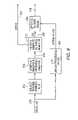
- FIG. 4is a functional block diagram of an AM HD RadioTM modem 130 showing the functional location of the carrier tracking of this invention.
- An input signal on line 132 from the digital down converteris subject to carrier tracking and automatic gain control as shown in block 134 .
- the resulting signal on line 136is subjected to a symbol tracking algorithm 138 that produces the BPSK signal on lines 140 and 142 , symbol vectors (in the time domain) on line 144 , and the analog modulated carrier on line 146 .
- BPSK processing, as shown in block 148produces block/frame sync and mode control information 150 that is used by functions illustrated in other blocks.
- An OFDM demodulator 152demodulates the time domain symbol vectors to produce frequency domain symbol vectors on line 154 .
- the equalizer 156processes the frequency domain symbol vectors in combination with the BPSK and carrier signals to produce equalized signals on line 158 and channel state information on line 160 . These signals are processed to produce branch metrics 162 , deinterleaved in a deinterleaver 164 , and mapped in a deframer 166 to produce soft decision bits on line 168 .
- a Viterbi decoder 170processes the soft decision bits to produce decoded program data units on line 172 .
- the modemprocesses these OFDM vectors in the following order (referring to FIG. 4 ): Carrier Tracking, Symbol Tracking, OFDM Demodulation & BPSK processing, and then Equalization.
- the input to the modemcomprises time domain vectors, or just a sequence of time samples; the Carrier Tracking operates in the time domain.
- the Symbol Trackingoperates on the time domain samples and outputs (symbol synchronized) time domain OFDM vectors, and also computes the middle 3 FFT bins (0, ⁇ 1) representing the main carrier and BPSK subcarriers in the frequency domain.
- the main carrier and the BPSK subcarriersare used for the equalization and are conveniently received from the symbol tracking, although they could also be received from the OFDM demodulation function (windowed FFT) having the same redundant 3 middle FFT bins.
- the Equalizeralways operates on the sequence of frequency domain OFDM vectors.
- the equalizeris comprised of two cascaded components, a flat fade equalizer followed by a partition equalizer with noise variance estimates used subsequently in the generation of channel state information (CSI).
- CSIchannel state information
- the partition equalizeroperates on each of the partitions of the received signal.
- each partitionconsists of a set of 25 OFDM subcarriers, spanning approximately 5 kHz per partition.
- the partitions of the all-digital IBOC signalcomprise a pair of primary partitions, a secondary partition and a tertiary partition, and are equalized independently.
- the secondary and tertiary partitions of the hybrid signalinvolve additional processing and combining techniques described below.
- Several other single subcarriersare also transmitted between the partitions and use a simpler equalization technique than described here.
- the flat fade compensation(equalizer) is described next.
- the flat fade compensationinvolves phase compensation using the main carrier phase, and magnitude equalization using the imaginary components of the BPSK signal. This flat fade compensation should be applied to all OFDM subcarriers.
- This symbolis one of a group of QAM symbols transmitted in the n th OFDM symbol at subcarrier frequency ⁇ c .
- the QAM symbolis transmitted using a complementary subcarrier pair to avoid AM crosstalk.
- s ( t )[ a ( n, 1)+ Q ( n, 1)] ⁇ w ( t ) ⁇ e j ⁇ 2 ⁇ c ⁇ t +[a ( n, ⁇ 1)+ Q ( n, ⁇ 1)] ⁇ w ( t ) ⁇ e ⁇ j ⁇ 2 ⁇ c ⁇ t
- the receiverdemodulates the signal, which has been added to the analog modulation component and is further corrupted by noise and phase error, to produce the following estimates of the symbols for the pair of subcarriers:
- the analog componentcan be extracted by summing the two components.
- the analog signalcan be reproduced using the real part of the result, or, more commonly, computing its magnitude.
- the BPSK sequenceis transmitted on the first pair of OFDM subcarriers on either side of the main carrier. These BPSK subcarriers are transmitted at a gain of G BPSK , relative to the main carrier at a level of 1. So each BPSK symbol can be recovered and scaled with the following expression:
- the magnitude estimateis generally less accurate than the absolute value of the imaginary computation when the phase error is small.
- the magnitudeis also more computationally complex, so we choose to avoid the magnitude computation in favor of the imaginary component computation.
- the estimate of the channel magnitude R(n)can be computed from B(n), or more directly from D(n,1) and D*(n, ⁇ 1).
- G BPSKabs ⁇ [ Im ⁇ ⁇ D ⁇ ( n , 1 ) ⁇ + Im ⁇ ⁇ D ⁇ ( n , - 1 ) ⁇ ] 2 ⁇ G BPSK . Notice that R(n) is a real-valued scalar.
- FIG. 5A functional block diagram of the flat fade equalizer 180 is presented in FIG. 5 .
- An input D(n) from the OFDM demodulatoris supplied on line 182 .
- the inputis a 256-sample vector for each symbol n.
- R(n)is computed as shown in block 184 and passed to a median filter 186 to produce a first filtered signal on line 188 .
- the first filtered signalis further filtered by a finite impulse response filter 190 to produce a second filtered signal on line 192 .
- the filtering for the BPSK magnitude signal R(n)includes a 7-tap median filter cascaded with a 7-tap FIR filter.
- This median filtercan be implemented by placing the samples of R(n) in a 7-element circular buffer, then computing the median of the 7 samples.
- the median filterhas a delay of 3 samples.
- the 7-tap FIR filterhas a delay of 3 samples and can be implemented using the following 7 coefficients:
- h ⁇ ( k )( 1 16 2 16 3 16 4 16 3 16 2 16 1 16 ) .
- the total delay of the median and FIR filtersis 6 samples.
- the filtered channel magnitudecan be expressed as
- the main carrier phaseis also corrected as a flat fade component. However, this phase should be filtered independently of the previous BPSK magnitude. This is due to the increased phase noise on carrier samples near pinchoff at the negative analog modulation peaks.
- the same FIR filtering 194 defined for the BPSK magnitudecan be used for the main carrier phase, although the median filtering should not be used, but replaced with an equivalent delay 196 to match the delay of the magnitude component.
- the main carrier samples C(n)can be computed independently over each OFDM symbol, or the value computed in the OFDM demodulation can be used.
- the filtering of the main carrier componentis as follows:
- the flat fade equalizer weightis the reciprocal of the filtered channel magnitude (with divide by zero protection, ⁇ ), while applying the conjugate of the main carrier phase, after an appropriate delay,
- W ffC ⁇ * ⁇ ( n - 6 ) max ⁇ [ R ⁇ ⁇ ( n - 6 ) , ⁇ ] ⁇ ⁇ C ⁇ ⁇ ( n - 6 ) ⁇
- the original inputis delayed as shown in block 200 and multiplied by W ff as shown in multiplier 202 to produce an output 256-sample vector for each new symbol n-6 after flat fade equalization on line 204 .
- Filtering for the BPSK magnitude signal R(n)includes a 7-tap median filter cascaded with a 7-tap FIR filter.
- Table 1shows the locations of interleaved symbols (indices), including training symbols “T” within each partition block. Each column represents a partition.
- an algorithmis used to compute the equalizer coefficients and associated noise variances estimated for each of the 25 elements (columns for subcarriers) of each OFDM symbol within a partition (for example, the upper primary partition).
- the equalizerbegins processing OFDM symbols as they are received. All partitions of the all-digital modes and the primary partitions of the hybrid mode are processed independently for each OFDM symbol containing 25 columns (per partition).
- the hybrid secondary partitionsare processed independently, and after complementary combining, allowing selection of the maximum metric, depending upon whether the analog audio bandwidth is limited to 5 kHz.
- the hybrid tertiary partitionsare processed only after complementary combining.
- Each column of a partitioncontains either 1 or 2 training symbols (complex), depending upon which of the 16 rows is processed.
- the training symbol locationsrepeat every 16 OFDM symbols (rows).
- the locations of the training symbolsare conveniently computed as a function of the particular row (modulo 16 ) of the OFDM symbol.
- the recent training symbolsare next collected in a 25-column vector TS, simply updating the column(s) of TS(col) corresponding to the recent column(s) of the OFDM symbol containing the training symbol.
- the medians and variances of adjacent groups of symbolsare computed after the adjacent group is updated with recent training symbols. Next the variances and medians are filtered using a two-dimensional recursive filter technique.
- equalizer coefficientsare computed from the filtered medians and equalization is applied to all the corresponding columns for the previous OFDM symbol, along with the updated noise variances (and reciprocals) for subsequent symbol processing. The details of this process are described next and presented in FIG. 6 .
- FIG. 6is a functional block diagram of an equalizer that can be used for each 25-column partition.
- the OFDM symbol OFDM(r,col)is input on line 210 .
- Training symbolsare collected as shown in block 212 .
- the medians and variancesare computed as shown in block 214 to produce median and variance signals on line 216 .
- These signalsare filtered and equalized in block 218 to produce an equalized variance signal on line 220 (for use in subsequent channel state information (CSI) estimates) and equalization coefficients on line 222 .
- CSIchannel state information
- the equalization coefficientsare applied to the input signal as shown in block 226 to produce an output signal on line 228 .
- the training symbol in a row rcan be updated using the following algorithm.
- the partition equalizerperforms several steps.
- Step 1Gather, collapse and update the Training Symbols into a convenient vector TS (representing the timely training symbol information) used in subsequent equalization processing.
- Step 2Create two, 25-column vectors labeled MED and logVAR to be used to store the computed median and log of the variance values for equalization and CSI. Median filtering of the local (time & freq) TS samples is used to produce a median value estimate of the TS. The outputs Med & logVAR are local estimates (not yet time or frequency (across subcarriers) smoothed) of these parameters.
- the column indicesequal the corresponding columns of the training symbols as they are received for each OFDM symbol. Then initialize the elements to zero.
- TS( 0 ) through TS( 7 )are used, and the missing TS( ⁇ 1 ) column is replaced with TS( 0 ) to provide 9 values for the median computation.
- the computed median and variance valuesare placed in MED(col) and logVAR(col).
- the following methodcan be used to identify the appropriate columns to update at this row r, and gather the appropriate TS samples for the 9-sample median and log variance computations:
- the next stepis to smooth (filter) the median and variance values over time and frequency (columns).
- the log of the varianceis used for smoothing the squared noise samples having a potentially large dynamic range over the subcarriers.
- the equalizer values EQare computed from MED 2 .
- the EQ valuesare generally the complex reciprocal of MED 2 values, but with divide protection.
- the variance values logVAR 2are used to compute VAREQ for subsequent CSI and branch metrics after adjustment for equalizer gains.
- Step 3Next smooth the MED and logVAR values over time and frequency (subcarriers).
- the time smoothing with the IIR filterresults in MED 1 & logVAR 1 .
- the frequency smoothing using one of the quadratic fit functionsresults in MED 2 & logVAR 2 . See first part of algorithm described below.
- Step 4The equalizer values EQ are computed from MED 2 .
- the EQ valuesare generally the complex reciprocal of MED 2 values, but with divide protection.
- the variance values logVAR 2are used to compute VAREQ for subsequent CSI and branch metrics after adjustment for equalizer gains. Note that the last line of the algorithm above computes VAREQ(col) in a manner that accommodates special conditions. It is not simply the antilog computation to convert logVAR (log of the variance estimate) to VAR. It accounts for the fact that the variance is computed on not-yet-equalized values, so an adjustment is made to be compatible with the equalized symbol values of the output. Further adjustment is made to avoid variance estimate errors when very high interference is present. Both of these adjustments are included in the factor max [Eqmagsq (col,max(Eqmagsq)/2] after the antilog.
- the algorithm described aboveuses a function called QF, which is a quadratic fit of the MED 1 or logVAR 1 matrices used to smooth the values across the columns (subcarriers) of these matrices.
- QFis a quadratic fit of the MED 1 or logVAR 1 matrices used to smooth the values across the columns (subcarriers) of these matrices.
- the smoothing of these valuesreduces the estimation and correction errors due to noise since the variation needing equalization is assumed to be smooth.
- the variation of these values across the columnscan be a result of several factors.
- One factoris due to a residual symbol tracking timing error causing a linear phase shift across the subcarriers. Since the filtering is done in the I and Q complex domain, and not phase and magnitude, the I and Q components resulting from this linear phase shift cannot be corrected exactly with a linear fit, but rather a quadratic fit for I and Q complex components provides sufficient accuracy.
- phase and amplitude perturbations due to frequency selective fading over the subcarrierscan also be corrected by the quadratic fit.
- Phase and amplitude ripple from analog filtering prior to OFDM demodulationcan be corrected if the ripple is small.
- Interferencealso tends to have a shape for logVAR that can be accommodated with a quadratic fit.
- the analog filter rippleis severe and deviates from a quadratic shape, then a different QF function is needed. Therefore two algorithm options are presented: the first QF function is best for correcting the variations due to residual symbol timing error, selective channel fading, and mild filter ripple; the second algorithm is designed to correct all these variations plus a more severe filter ripple.
- the first QF functionestimates three points over the subcarriers to which a quadratic shape is fitted to perform the smoothing correction. These points are estimated using FIR filters at the middle and two extreme endpoints of the subcarrier span. The middle point is properly estimated using a symmetric FIR filter over the middle subcarrier. The FIR filters at the endpoints have a centroid that is several bins from the ends. Although the quadratic fit could be normally designed to use the proper centroids near the endpoints and extrapolate the remaining subcarriers at the extreme ends, the performance tends to be better if the centroids are assumed to be located at the extreme subcarrier locations. The reason is that the extrapolation tends to accentuate the curvature of the quadratic fit in the presence of noise. However the algorithm can be modified to place the centroids at the location that yields the best overall performance.
- Step 4aThe first quadratic fit function is intended to smooth the estimates with a partition shape (assumed quadratic) that provides near-optimum smoothing given likely channel conditions such as time-offset and selective fading properties. This is accomplished using the following algorithm.
- An alternate quadratic fit function QFis provided to accommodate IF filters with excessive ripple and group delay or gain variations. This function is different from the first since a different quadratic curve is used at each subcarrier location to form the FIR filter coefficients. These quadratic curves are pre-computed and stored in a 25 by 25 matrix W to be used as a multiplier for the row of 25 values from the subcarriers to be filtered. So instead of computing the quadratic fit across the 25 subcarriers for each new OFDM symbol as in the first algorithm, the second algorithm simply multiplies the vector of 25 subcarrier values by the matrix W for each OFDM symbol time.
- This alternate QF functionis applied in a similar manner as a method known as the Savitsky-Golay (SG) procedure; however, the alternate QF function generates the coefficients in a different manner resulting in improved filtering gain against noise while solving the endpoint dilemma.
- the SG procedurecomputes a least-squares fit centered on each point to smooth the data for that point. The result is a set of FIR filter coefficients about each subcarrier location to be smoothed. Two factors motivate the use of least squares smoothing.
- the SG procedureexploits the properties of manipulated Vandermonde matrices to generate the FIR coefficients, generating a unique set of FIR filter coefficients for each subcarrier location to be smoothed. Although the SG procedure produces FIR filter coefficients that result in an unbiased estimate of each smoothed subcarrier value, the actual set of FIR coefficients do not have the best noise reduction filtering properties due to the excessive use of negative coefficient values.
- the alternate QF functionuses the best possible quadratic fit FIR coefficients for noise reduction filtering or smoothing, while preserving the zero bias property of the SG procedure. Furthermore, the alternate QF function has more flexibility in establishing the span of FIR filter smoothing about the subcarrier locations.
- the span of the nonzero FIR filter coefficients for each subcarrier locationis set to 15 nonzero coefficients to accommodate the anticipated variability of values across the 25 subcarriers in the partition, although this can be adjusted.
- the shape of the FIR coefficientsis a quadratic function with four additional constraints defined as follows:
- Constraint 1The number of nonzero FIR filter coefficients is 15, with 10 zero coefficients remaining.
- the center nonzero coefficientis normally located on the subcarrier to be smoothed resulting in a symmetric FIR filter property, except that the 7 subcarriers on either end are constrained by using the 15 subcarrier locations on that end for the nonzero coefficients.
- Constraint 2Each set of the 25 sets of 25 FIR coefficients, having 15 nonzero coefficients and 10 zero coefficients, must sum to unity so that each FIR filter has a dc gain of one for each subcarrier location.
- Constraint 3The centroid of the FIR filter for subcarrier m must also be m to ensure an unbiased estimate when the slope of the subcarrier data is assumed to be piecewise linear.
- Constraint 4Although the best noise reduction can be achieved by minimizing the sums of the squares of the coefficients, this does not provide the best local estimate for each subcarrier location, and would result in 15 linear coefficients for each FIR filter. A better constraint is to ensure that the quadratic function crosses zero at the unused coefficient locations just outside the 15 nonzero coefficients. This is possible for the 11 subcarrier locations 7 through 17 , but this constraint cannot be met for the other subcarrier locations affected by the endpoint dilemma. Then the outer subcarrier locations have the zero crossing constraint only toward the inner point beyond the FIR coefficient span.
- Constraint 1simply establishes the range of the 15 nonzero coefficients for each of the 25 FIR filters having a quadratic characteristic over that range.
- Constraints 2, 3 and 4constitute the three equations necessary to determine the quadratic coefficients a m , b m and c m for each FIR filter.
- An algorithm for generating the alternate QF1(x) FIR filter coefficient matrix Wis defined next, and the resulting coefficient values for W are presented as shown below.
- Step 4bAn alternate quadratic fit function QF is provided to accommodate IF filters with excessive ripple and group delay or gain variations. This function is different from the first since a different quadratic curve is used at each subcarrier location to form the FIR filter coefficients. These quadratic curves are pre-computed and stored in a 25 by 25 matrix W to be used as a multiplier for the row of 25 values from the subcarriers to be filtered. So instead of computing the quadratic fit across the 25 subcarriers for each new OFDM symbol as in the first algorithm, the second algorithm simply multiplies the vector of 25 subcarrier values by the matrix W for each OFDM symbol time. These are subjected to constraints 1-4, which result in the following algorithm.
- Another alternate filter QF2(x)can be designed using all 25 possible nonzero coefficients for each FIR filter.
- This filterhas a characteristic more similar to the first QF(x) filter, but is constructed in the matrix form W of the alternate filter.
- the inventioninvolves the adaptive complementary combining of the secondary partitions before equalization.
- the two independent secondary partitionsare equalized independently, along with the associated VAREQ estimates.
- the branch metricsare computed independently and redundantly for all secondary soft code bits in the partition.
- the corresponding branch metricsare then added to produce one set of branch metrics.
- the equalizationis also performed on the complementary combined secondary partitions to produce another set of branch metrics for the same set of secondary soft code bits. Then for each secondary soft code bit, the higher branch metric is selected as output for the corresponding secondary soft code bits.
- the method of this inventiondoes not make use of the analog bandwidth information; instead both independent and combined equalizations are performed, and later the maximum branch metric is selected. This yields more robust performance, especially when the analog bandwidth somewhat exceeds 5 kHz.
- the tertiary subcarriersare always complementary combined prior to equalization. Tertiary equalization is then performed as described.
- the two secondary partitionsare processed both independently and complementary combined, yielding three sets of equalized branch metrics for the single set of secondary soft code bits. The method of combining these three sets of branch metrics is described next.
Landscapes
- Engineering & Computer Science (AREA)
- Signal Processing (AREA)
- Computer Networks & Wireless Communication (AREA)
- Power Engineering (AREA)
- Cable Transmission Systems, Equalization Of Radio And Reduction Of Echo (AREA)
- Digital Transmission Methods That Use Modulated Carrier Waves (AREA)
- Noise Elimination (AREA)
Abstract
Description
s(t)=[a(n,1)+Q(n,1)]·w(t)·ej·2·π·ƒ
whereQ(n,−1)=−Q*(n,1) anda(n,−1)=a*(n,1).
D(n,1)=∫(s(t)+n(t))·w(t)e−j·2·π·ƒ
D(n,−1)=∫(s(t)+n(t))·w(t)ej·2·π·ƒf
R(n)=|B(n)|, or R(n)=abs[Im{B(n)}].
Notice that R(n) is a real-valued scalar.
where the median is computed over 7 samples.
The flat fade equalizer weight is the reciprocal of the filtered channel magnitude (with divide by zero protection, ε), while applying the conjugate of the main carrier phase, after an appropriate delay,
| TABLE 1 | ||||||||||||||
| 0 | 1 | 2 | 3 | 4 | 5 | 6 | 7 | 8 | 9 | 10 | 11 | 12 | ||
| A = | 0 | 0 | “T” | 728 | 692 | 631 | 595 | 534 | 498 | 437 | 376 | 340 | 279 | 243 |
| 1 | 150 | 114 | 53 | 17 | “T” | 745 | 684 | 648 | 587 | 526 | 490 | 429 | 393 | |
| 2 | 300 | 264 | 203 | 167 | 106 | 70 | 9 | “T” | 737 | 676 | 640 | 579 | 543 | |
| 3 | 450 | 414 | 353 | 317 | 256 | 220 | 159 | 123 | 62 | 1 | “T” | 729 | 693 | |
| 4 | 600 | 564 | 503 | 467 | 406 | 370 | 309 | 273 | 212 | 151 | 115 | 54 | 18 | |
| 5 | “T” | 714 | 653 | 617 | 556 | 520 | 459 | 423 | 362 | 301 | 265 | 204 | 168 | |
| 6 | 125 | 89 | 28 | “T” | 706 | 670 | 609 | 573 | 512 | 451 | 415 | 354 | 318 | |
| 7 | 275 | 239 | 178 | 142 | 81 | 45 | “T” | 723 | 662 | 601 | 565 | 504 | 468 | |
| 8 | 425 | 389 | 328 | 292 | 231 | 195 | 134 | 98 | 37 | “T” | 715 | 654 | 618 | |
| 9 | 575 | 539 | 478 | 442 | 381 | 345 | 284 | 248 | 187 | 126 | 90 | 29 | “T” | |
| 10 | 725 | 689 | 628 | 592 | 531 | 495 | 434 | 398 | 337 | 276 | 240 | 179 | 143 | |
| 11 | 50 | 14 | “T” | 742 | 681 | 645 | 584 | 548 | 487 | 426 | 390 | 329 | 293 | |
| 12 | 200 | 164 | 103 | 67 | 6 | “T” | 734 | 698 | 637 | 576 | 540 | 479 | 443 | |
| 13 | 350 | 314 | 253 | 217 | 156 | 120 | 59 | 23 | “T” | 726 | 690 | 629 | 593 | |
| 14 | 500 | 464 | 403 | 367 | 306 | 270 | 209 | 173 | 112 | 51 | 15 | “T” | 743 | |
| 15 | 650 | 614 | 553 | 517 | 456 | 420 | 359 | 323 | 262 | 201 | 165 | 104 | 68 | |
| 16 | 25 | “T” | 703 | 667 | 606 | 570 | 509 | 473 | 412 | 351 | 315 | 254 | 218 | |
| 17 | 175 | 139 | 78 | 42 | “T” | 720 | 659 | 623 | 562 | 501 | 465 | 404 | 368 | |
| 18 | 325 | 289 | 228 | 192 | 131 | 95 | 34 | “T” | 712 | 651 | 615 | 554 | 518 | |
| 19 | 475 | 439 | 378 | 342 | 281 | 245 | 184 | 148 | 87 | 26 | “T” | 704 | 668 | |
| 20 | 625 | 589 | 528 | 492 | 431 | 395 | 334 | 298 | 237 | 176 | 140 | 79 | 43 | |
| 21 | “T” | 739 | 678 | 642 | 581 | 545 | 484 | 448 | 387 | 326 | 290 | 229 | 193 | |
| 22 | 100 | 64 | 3 | “T” | 731 | 695 | 634 | 598 | 537 | 476 | 440 | 379 | 343 | |
| 23 | 250 | 214 | 153 | 117 | 56 | 20 | “T” | 748 | 687 | 626 | 590 | 529 | 493 | |
| 24 | 400 | 364 | 303 | 267 | 206 | 170 | 109 | 73 | 12 | “T” | 740 | 679 | 643 | |
| 25 | 550 | 514 | 453 | 417 | 356 | 320 | 259 | 223 | 162 | 101 | 65 | 4 | “T” | |
| 26 | 700 | 664 | 603 | 567 | 506 | 470 | 409 | 373 | 312 | 251 | 215 | 154 | 118 | |
| 27 | 75 | 39 | “T” | 717 | 656 | 620 | 559 | 523 | 462 | 401 | 365 | 304 | 268 | |
| 28 | 225 | 189 | 128 | 92 | 31 | “T” | 709 | 673 | 612 | 551 | 515 | 454 | 418 | |
| 29 | 375 | 339 | 278 | 242 | 181 | 145 | 84 | 48 | “T” | 701 | 665 | 604 | 568 | |
| 30 | 525 | 489 | 428 | 392 | 331 | 295 | 234 | 198 | 137 | 76 | 40 | “T” | 718 | |
| 31 | 675 | 639 | 578 | 542 | 481 | 445 | 384 | 348 | 287 | 226 | 190 | 129 | 93 | |
| 13 | 14 | 15 | 16 | 17 | 18 | 19 | 20 | 21 | 22 | 23 | 24 | ||
| A = | 0 | 182 | 146 | 85 | 49 | “T” | 702 | 666 | 605 | 569 | 508 | 472 | 411 | ||
| 1 | 332 | 296 | 235 | 199 | 138 | 77 | 41 | “T” | 719 | 658 | 622 | 561 | |||
| 2 | 482 | 446 | 385 | 349 | 288 | 227 | 191 | 130 | 94 | 33 | “T” | 711 | |||
| 3 | 632 | 596 | 535 | 499 | 438 | 377 | 341 | 280 | 244 | 183 | 147 | 86 | |||
| 4 | “T” | 746 | 685 | 649 | 588 | 527 | 491 | 430 | 394 | 333 | 297 | 236 | |||
| 5 | 107 | 71 | 10 | “T” | 738 | 677 | 641 | 580 | 544 | 483 | 447 | 386 | |||
| 6 | 257 | 221 | 160 | 124 | 63 | 2 | “T” | 730 | 694 | 633 | 597 | 536 | |||
| 7 | 407 | 371 | 310 | 274 | 213 | 152 | 116 | 55 | 19 | “T” | 747 | 686 | |||
| 8 | 557 | 521 | 460 | 424 | 363 | 302 | 266 | 205 | 169 | 108 | 72 | 11 | |||
| 9 | 707 | 671 | 610 | 574 | 513 | 452 | 416 | 355 | 319 | 258 | 222 | 161 | |||
| 10 | 82 | 46 | “T” | 724 | 663 | 602 | 566 | 505 | 469 | 408 | 372 | 311 | |||
| 11 | 232 | 196 | 135 | 99 | 38 | “T” | 716 | 655 | 619 | 558 | 522 | 461 | |||
| 12 | 382 | 346 | 285 | 249 | 188 | 127 | 91 | 30 | “T” | 708 | 672 | 611 | |||
| 13 | 532 | 496 | 435 | 399 | 338 | 277 | 241 | 180 | 144 | 83 | 47 | “T” | |||
| 14 | 682 | 646 | 585 | 549 | 488 | 427 | 391 | 330 | 294 | 233 | 197 | 136 | |||
| 15 | 7 | “T” | 735 | 699 | 638 | 577 | 541 | 480 | 444 | 383 | 347 | 286 | |||
| 16 | 157 | 121 | 60 | 24 | “T” | 727 | 691 | 630 | 594 | 533 | 497 | 436 | |||
| 17 | 307 | 271 | 210 | 174 | 113 | 52 | 16 | “T” | 744 | 683 | 647 | 586 | |||
| 18 | 457 | 421 | 360 | 324 | 263 | 202 | 166 | 105 | 69 | 8 | “T” | 736 | |||
| 19 | 607 | 571 | 510 | 474 | 413 | 352 | 316 | 255 | 219 | 158 | 122 | 61 | |||
| 20 | “T” | 721 | 660 | 624 | 563 | 502 | 466 | 405 | 369 | 308 | 272 | 211 | |||
| 21 | 132 | 96 | 35 | “T” | 713 | 652 | 616 | 555 | 519 | 458 | 422 | 361 | |||
| 22 | 282 | 246 | 185 | 149 | 88 | 27 | “T” | 705 | 669 | 608 | 572 | 511 | |||
| 23 | 432 | 396 | 335 | 299 | 238 | 177 | 141 | 80 | 44 | “T” | 722 | 661 | |||
| 24 | 582 | 546 | 485 | 449 | 388 | 327 | 291 | 230 | 194 | 133 | 97 | 36 | |||
| 25 | 732 | 696 | 635 | 599 | 538 | 477 | 441 | 380 | 344 | 283 | 247 | 186 | |||
| 26 | 57 | 21 | “T” | 749 | 688 | 627 | 591 | 530 | 494 | 433 | 397 | 336 | |||
| 27 | 207 | 171 | 110 | 74 | 13 | “T” | 741 | 680 | 644 | 583 | 547 | 486 | |||
| 28 | 357 | 321 | 260 | 224 | 163 | 102 | 66 | 5 | “T” | 733 | 697 | 636 | |||
| 29 | 507 | 471 | 410 | 374 | 313 | 252 | 216 | 155 | 119 | 58 | 22 | “T” | |||
| 30 | 657 | 621 | 560 | 524 | 463 | 402 | 366 | 305 | 269 | 208 | 172 | 111 | |||
| 31 | 32 | “T” | 710 | 674 | 613 | 552 | 516 | 455 | 419 | 358 | 322 | 261 | |||
- “Algorithm to update TS for row r”
- col=mod(3·r+1, 16) ; “identify which column has new TS”
- TS(col)=OFDM(r,col)
- if col<9 then TS(col+16)=OFDM(r,col+16); “if second TS in this row”.
| “Algorithm to update MED and log VAR vectors, delay = 6 symbols” |
| col = mod(3 · r + 15, 16) ; “identify first TS col for r − 6” |
| FOR m = 0 to 8 ; “gather 9 adjacent TS to place in buffer for MED & log |
| VAR computation” |
| colm = col + m − 4 | |
| TSmedbuff(m) = TS(TScolindx) |
| MED(col) = median(TSmedbuff) ; “complex median, separate real & |
| imaginary” |
| “compute log base2 of VAR samples (vector)” | |
| if col < 9 then ; |
| “update second TS in this row if exists - - - - - - - - - - - - - - - -” |
| col2 = col + 16 |
| FOR m = 0 to 8 |
| colm = col2 + m − 4 | |
| TSmedbuff(m) = TS(TScolindx) |
| MED(col2) = median(TSmedbuff) ; “complex median, separate real & |
| imaginary” |
| end if. |
| “Algorithm to compute EQ & VAREQ from MED & log VAR, filter |
| delay = 16 symbols” |
| “IIR filter MED and log VAR each col to get MED1 and log VAR1, q = |
| 1/8 IIR coef” |
| MED1 = (1 − q) · MED1 + q · MED ; |
| logVAR1 = (1 − q) · logVAR1 + q · logVAR ; |
| “Smooth MED1 and logVAR1 across cols using quadratic - fit |
| interpolator” |
| “MED2 & logVAR2 are the freq - smoothed median and variance |
| estimates” |
| MED2 = QF(MED1) ; “compute quadratic fit using QF algorithm” |
| logVAR2 = QF(log VAR1) ; “compute quadratic fit using QF algorithm” |
| “Compute equalizer coefficients EQ from MED2” |
| medsq(col) = |MED2(col)|2 ; col = 0 . . . 24 “save squared |
| magnitudes” |
| “Compute antilog and equalize log VAR2 to produce VAREQ” |
| EQmagsq(col) = |EQ(col)|2 ; col = 0 . . . 24 |
| VAREQ(col) = 2logVAR2(col)· max[EQmagsq(col), max(EQmagsq)/2] ; |
| col = 0 . . . 24. |
The EQ(col) values are then applied to the corresponding data-bearing symbols to produce OFDMEQ(col) values for each column of the OFDM symbol (delayed by 22 OFDM symbols to account for the EQ processing delay). The VAREQ(col) values are used for subsequent CSI processing.
OFDMEQ(col)=OFDM(col)·EQ(col);col=0 . . . 24 “equalize delayed OFDM symbol.
p=max(0, min(17, m−7)) ; “p is the first nonzero coefficient location”.
for the kth coefficient estimating the mth subcarrier.
ym(k)=am·k2+bm·k+cm; “quadratic for the kth coef for the mth subcarrier”
ym(p−1)=0; “constraint for m=7 . . . 24”
ym(p+15)=0 ; “constraint for m=0 . . . 17”.
| “QF1(x), Alternate Quadratic Fit Matrix function, input row | ||
| vector x, output vector y.” | ||
| “first compute prestored coefficient matrix W (25 by 25)” | ||
| FOR m = 0 to 7 | ||
| c(m) = −225 · a(m) − 15 · b(m) | |
| FOR k = 0 to 14 |
| W (k, m) = a(m) · k2+ b(m) · k + c(m) | |
| W (24 − k, 24 − m) = W (k, m) |
| FOR m = 8 to 16 |
| FOR k = 0 to 14 |
| W (k + m − 7, m) = W (k, 7) |
| “This is the end of the prestored computation for filter matrix W” |
| “compute filtered output vector y for each new OFDM symbol” |
| y = x · W ; “matrix multiply yields output vector y”. |
Step 4c: A third alternative quadratic fit is described below.
| “QF2(x), Alternate Quadratic Fit Matrix function, input row | ||
| vector x, output vector y.” | ||
| “first compute prestored coefficient matrix W (25 by 25)” | ||
| FOR m = 0 to 13 | ||
| FOR k = 0 to 24 |
| W (k, m) = a(m) · k2+ b(m) · k + c(m) | |
| W (24 −k, 24 − m) = W (k, m) |
| “This is the end of the prestored computation for filter matrix W” | ||
| “compute filtered output vector y for each new OFDM symbol” | ||
| y = x W ; “matrix multiply yields output row vector y”. | ||
Claims (15)
Priority Applications (18)
| Application Number | Priority Date | Filing Date | Title |
|---|---|---|---|
| US11/272,978US7697620B2 (en) | 2005-11-14 | 2005-11-14 | Equalizer for AM in-band on-channel radio receivers |
| TW095139909ATWI406542B (en) | 2005-11-14 | 2006-10-27 | Equalizer for am in-band on-channel radio receivers |
| ARP060104915AAR056796A1 (en) | 2005-11-14 | 2006-11-09 | METHODS FOR UPDATING OFDM SYMBOL VECTORS RECEIVED IN A RADIO SIGNAL IN THE BANDA AM CHANNEL, METHOD FOR ESTIMATING VARIANCES OF THE RECEIVED TRAINING SYMBOL INFORMATION AND RADIO SIGNAL RECEIVERS IN THE BANDA AMBOL AND SIMBOL BIDD VECTORS |
| RU2008123827/09ARU2008123827A (en) | 2005-11-14 | 2006-11-13 | EQUALIZER FOR AM-RADIO RECEIVERS OF "IN-BAND ON-CHANNEL" TECHNOLOGY |
| MYPI20081550AMY149578A (en) | 2005-11-14 | 2006-11-13 | Equalizer for am in-band on-channel radio receivers |
| EP06837438AEP1949587A2 (en) | 2005-11-14 | 2006-11-13 | Equalizer for am in-band on-channel radio receivers |
| PCT/US2006/043983WO2007059028A2 (en) | 2005-11-14 | 2006-11-13 | Equalizer for am in-band on-channel radio receivers |
| AU2006315619AAU2006315619A1 (en) | 2005-11-14 | 2006-11-13 | Equalizer for AM in-band on-channel radio receivers |
| JP2008540246AJP2009516430A (en) | 2005-11-14 | 2006-11-13 | AM in-band on-channel radio receiver equalizer |
| HK09102365.4AHK1124973B (en) | 2005-11-14 | 2006-11-13 | Equalizer for am in-band on-channel radio receivers |
| CN201110065869.0ACN102098251B (en) | 2005-11-14 | 2006-11-13 | Equalizer for AM in-band on-channel radio receivers |
| CN2006800425467ACN101310494B (en) | 2005-11-14 | 2006-11-13 | Equalizer for AM In-Band On-Channel Wireless Receiver |
| CA2628166ACA2628166C (en) | 2005-11-14 | 2006-11-13 | Equalizer for am in-band on-channel radio receivers |
| BRPI0618553-3ABRPI0618553A2 (en) | 2005-11-14 | 2006-11-13 | methods of equalizing ofdm symbol vectors in a radio signal and estimating the information variances of training symbols in a radio signal, and receiver for receiving a radio signal |
| KR1020087014523AKR101229150B1 (en) | 2005-11-14 | 2006-11-13 | Equalizer for am in-band on-channel radio receivers |
| CN201410387746.2ACN104104632B (en) | 2005-11-14 | 2006-11-13 | Balanced device for AM in-band on-channel wireless receivers |
| US12/710,534US8442170B2 (en) | 2005-11-14 | 2010-02-23 | Equalizer for AM in-band on-channel radio receivers |
| US13/802,994US8923378B2 (en) | 2005-11-14 | 2013-03-14 | Equalizer for AM in-band on-channel radio receivers that does not require analog signal bandwidth information |
Applications Claiming Priority (1)
| Application Number | Priority Date | Filing Date | Title |
|---|---|---|---|
| US11/272,978US7697620B2 (en) | 2005-11-14 | 2005-11-14 | Equalizer for AM in-band on-channel radio receivers |
Related Child Applications (1)
| Application Number | Title | Priority Date | Filing Date |
|---|---|---|---|
| US12/710,534DivisionUS8442170B2 (en) | 2005-11-14 | 2010-02-23 | Equalizer for AM in-band on-channel radio receivers |
Publications (2)
| Publication Number | Publication Date |
|---|---|
| US20070110020A1 US20070110020A1 (en) | 2007-05-17 |
| US7697620B2true US7697620B2 (en) | 2010-04-13 |
Family
ID=37913586
Family Applications (3)
| Application Number | Title | Priority Date | Filing Date |
|---|---|---|---|
| US11/272,978Active2028-11-29US7697620B2 (en) | 2005-11-14 | 2005-11-14 | Equalizer for AM in-band on-channel radio receivers |
| US12/710,534Active2026-09-21US8442170B2 (en) | 2005-11-14 | 2010-02-23 | Equalizer for AM in-band on-channel radio receivers |
| US13/802,994ActiveUS8923378B2 (en) | 2005-11-14 | 2013-03-14 | Equalizer for AM in-band on-channel radio receivers that does not require analog signal bandwidth information |
Family Applications After (2)
| Application Number | Title | Priority Date | Filing Date |
|---|---|---|---|
| US12/710,534Active2026-09-21US8442170B2 (en) | 2005-11-14 | 2010-02-23 | Equalizer for AM in-band on-channel radio receivers |
| US13/802,994ActiveUS8923378B2 (en) | 2005-11-14 | 2013-03-14 | Equalizer for AM in-band on-channel radio receivers that does not require analog signal bandwidth information |
Country Status (13)
| Country | Link |
|---|---|
| US (3) | US7697620B2 (en) |
| EP (1) | EP1949587A2 (en) |
| JP (1) | JP2009516430A (en) |
| KR (1) | KR101229150B1 (en) |
| CN (3) | CN104104632B (en) |
| AR (1) | AR056796A1 (en) |
| AU (1) | AU2006315619A1 (en) |
| BR (1) | BRPI0618553A2 (en) |
| CA (1) | CA2628166C (en) |
| MY (1) | MY149578A (en) |
| RU (1) | RU2008123827A (en) |
| TW (1) | TWI406542B (en) |
| WO (1) | WO2007059028A2 (en) |
Cited By (5)
| Publication number | Priority date | Publication date | Assignee | Title |
|---|---|---|---|---|
| US20080219338A1 (en)* | 2007-03-09 | 2008-09-11 | Rabih Chrabieh | Quadrature modulation rotating training sequence |
| US20080219379A1 (en)* | 2007-03-09 | 2008-09-11 | Rabih Chrabieh | Quadrature imbalance mitigation using unbiased training sequences |
| US20080219339A1 (en)* | 2007-03-09 | 2008-09-11 | Qualcomm Incorporated | Channel estimation using frequency smoothing |
| US8064550B2 (en) | 2007-03-09 | 2011-11-22 | Qualcomm, Incorporated | Quadrature imbalance estimation using unbiased training sequences |
| US8660214B1 (en)* | 2012-12-09 | 2014-02-25 | Phuong Thu-Minh Huynh | Quadrature bandpass-sampling OFDM receiver |
Families Citing this family (13)
| Publication number | Priority date | Publication date | Assignee | Title |
|---|---|---|---|---|
| US8428158B2 (en)* | 2006-03-16 | 2013-04-23 | Intel Corporation | Method for channel estimation using recursive filtering and multicarrier receiver with interference-aware demodulation |
| JP5114315B2 (en)* | 2008-06-27 | 2013-01-09 | 京楽産業.株式会社 | Multiplex transmission apparatus and multiple transmission method |
| US8743823B2 (en)* | 2009-02-12 | 2014-06-03 | Qualcomm Incorporated | Transmission with collision detection and mitigation for wireless communication |
| US8842750B2 (en)* | 2010-12-21 | 2014-09-23 | Intel Corporation | Channel estimation for DVB-T2 demodulation using an adaptive prediction technique |
| CN103501211A (en)* | 2013-10-08 | 2014-01-08 | 苏州东奇信息科技股份有限公司 | Composite modulation system compatible with medium-wave analogue amplitude modulation (AM) broadcast |
| US9143364B2 (en)* | 2013-10-10 | 2015-09-22 | Broadcom Corporation | IQ imbalance estimation using broadcast signals |
| US10436059B2 (en)* | 2014-05-12 | 2019-10-08 | Simmonds Precision Products, Inc. | Rotating stall detection through ratiometric measure of the sub-synchronous band spectrum |
| CN106712826B (en)* | 2015-11-13 | 2020-09-04 | 华为技术有限公司 | Data transmission method and device |
| US10171280B2 (en)* | 2016-08-01 | 2019-01-01 | Allen LeRoy Limberg | Double-sideband COFDM signal receivers that demodulate unfolded frequency spectrum |
| CN107895079B (en)* | 2017-11-14 | 2021-04-27 | 东南大学 | Full-band UWB Antenna Circuit Model |
| CN112865822A (en)* | 2019-11-28 | 2021-05-28 | 苏州东奇信息科技股份有限公司 | Audio interference resisting method for analog-digital mixed amplitude modulation broadcast receiver |
| US11146422B1 (en)* | 2020-07-29 | 2021-10-12 | U-Blox Ag | Method and system for adjusting the bandwidth of a frequency domain smoothing filter for channel tracking loop in an OFDM communication system |
| CN119945863B (en)* | 2025-01-24 | 2025-09-12 | 苏州市江海通讯发展实业有限公司 | BPSK+DSSS differential recursive demodulation method and device based on multi-phase weighted signal synthesis |
Citations (14)
| Publication number | Priority date | Publication date | Assignee | Title |
|---|---|---|---|---|
| US5559830A (en) | 1995-01-23 | 1996-09-24 | Xetron Corp. | Equalization system for AM compatible digital receiver |
| US5588022A (en) | 1994-03-07 | 1996-12-24 | Xetron Corp. | Method and apparatus for AM compatible digital broadcasting |
| US5859876A (en) | 1995-01-03 | 1999-01-12 | Dapper; Mark J. | Method and apparatus for improving AM compatible digital broadcast analog fidelity |
| US6292511B1 (en) | 1998-10-02 | 2001-09-18 | Usa Digital Radio Partners, Lp | Method for equalization of complementary carriers in an AM compatible digital audio broadcast system |
| US6295317B1 (en) | 1998-10-02 | 2001-09-25 | Usa Digital Radio Partners, Lp | Method and apparatus for demodulating and equalizing an AM compatible digital audio broadcast signal |
| EP1232591A1 (en) | 1999-11-10 | 2002-08-21 | Ibiquity Digital Corporation | Method and apparatus for transmission and reception of fm in-band on-channel digital audio broadcasting |
| US20040146123A1 (en) | 2003-01-28 | 2004-07-29 | Yhean-Sen Lai | Equalization in orthogonal frequency domain multiplexing |
| US20040161066A1 (en) | 2003-02-19 | 2004-08-19 | Chien-Meen Hwang | Minimum equalization error based channel estimator |
| US20040162839A1 (en)* | 2002-11-27 | 2004-08-19 | Zyvex Corporation | Isosurface extraction into splat hierarchy |
| US20050101264A1 (en)* | 2002-08-05 | 2005-05-12 | California Amplifier, Inc. | Wireless communications structures and methods utilizing frequency domain spatial processing |
| US6898249B2 (en) | 2002-12-17 | 2005-05-24 | Ibiquity Digital Corporation | Method and apparatus for AM digital audio broadcasting with amplitude scaled tertiary subcarriers |
| US20050141657A1 (en)* | 2003-12-30 | 2005-06-30 | Maltsev Alexander A. | Adaptive channel equalizer for wireless system |
| US20060013329A1 (en)* | 2004-07-14 | 2006-01-19 | Samsung Electronics Co., Ltd. | Signal transmitting device and method of multiple-antenna system |
| US20060052062A1 (en)* | 2003-01-29 | 2006-03-09 | Ralf Heddergott | Maximum likelihood estimation of the channel coefficients and of the DC offset in a digital baseband signal of a radio receiver using the sage algorithm |
Family Cites Families (23)
| Publication number | Priority date | Publication date | Assignee | Title |
|---|---|---|---|---|
| EP0602249B1 (en)* | 1992-06-18 | 2002-08-28 | Oki Electric Industry Company, Limited | Maximum likelihood sequence estimating device and method therefor |
| JP3351163B2 (en)* | 1994-07-27 | 2002-11-25 | 株式会社日立製作所 | Information recording / reproducing device and signal processing circuit |
| WO1998037542A1 (en)* | 1997-02-21 | 1998-08-27 | Lernout & Hauspie Speech Products N.V. | Accelerated convolution noise elimination |
| JP2004503994A (en)* | 2000-06-12 | 2004-02-05 | コーニンクレッカ フィリップス エレクトロニクス エヌ ヴィ | Channel equalizer |
| JP2002043990A (en)* | 2000-07-21 | 2002-02-08 | Mitsubishi Electric Corp | Receiver for wireless communication |
| US6904100B1 (en)* | 2000-09-29 | 2005-06-07 | Charles Christopher Romaniuk | Pulse controlled phase modulator |
| US6985523B2 (en)* | 2001-01-10 | 2006-01-10 | Hughes Electronics Corp. | Method and system for adaptive equalization for receivers in a wide-band satellite communications system |
| US6612149B2 (en) | 2001-02-15 | 2003-09-02 | Abbott Laboratories | Method and apparatus for calibration of instruments that monitor the concentration of a sterilant in a system |
| US7001340B2 (en) | 2001-03-16 | 2006-02-21 | Chung-Yuan Lin | Assessment of concentration of inhalational compounds in the brain |
| EP1251463A1 (en)* | 2001-04-20 | 2002-10-23 | BTS Media Solutions GmbH | Arrangement for processing video signals |
| US7103112B2 (en)* | 2001-12-04 | 2006-09-05 | Conexant, Inc. | Transmit frequency domain equalizer |
| DE60206356T2 (en)* | 2002-04-16 | 2006-05-11 | Sony International (Europe) Gmbh | Orthogonal frequency division multiplexing (OFDM) with channel prediction |
| AU2003250416A1 (en)* | 2002-08-13 | 2004-02-25 | Koninklijke Philips Electronics N.V. | Joint channel and noise variance estimation in a wideband ofdm system |
| US7352817B2 (en)* | 2002-09-27 | 2008-04-01 | Ibiquity Digital Corporation | Method and apparatus for interleaving signal bits in a digital audio broadcasting system |
| FR2851098B1 (en)* | 2003-02-10 | 2006-08-25 | Nortel Networks Ltd | METHOD OF PROCESSING A SIGNAL BY A RADIO RECEIVER AND RADIO RECEIVER FOR IMPLEMENTING THE METHOD |
| US7127008B2 (en)* | 2003-02-24 | 2006-10-24 | Ibiquity Digital Corporation | Coherent AM demodulator using a weighted LSB/USB sum for interference mitigation |
| FR2853417B1 (en)* | 2003-04-01 | 2006-07-14 | Thales Sa | SIGNAL PROCESSING METHOD, AND ACTIVE SONAR USING THE SAME |
| US20050074037A1 (en)* | 2003-10-06 | 2005-04-07 | Robin Rickard | Optical sub-carrier multiplexed transmission |
| US7305056B2 (en)* | 2003-11-18 | 2007-12-04 | Ibiquity Digital Corporation | Coherent tracking for FM in-band on-channel receivers |
| US7340010B2 (en)* | 2004-01-26 | 2008-03-04 | Ibiquity Digital Corporation | Forward error correction coding for hybrid AM in-band on-channel digital audio broadcasting systems |
| US7809342B2 (en)* | 2005-02-08 | 2010-10-05 | E-Radio Usa, Inc. | Systems and methods for providing product information over a carrier wave |
| US20060209993A1 (en)* | 2005-02-18 | 2006-09-21 | Wei Lu | Demodulator and receiver for pre-coded partial response signals |
| US20070021085A1 (en)* | 2005-07-25 | 2007-01-25 | Ibiquity Digital Corporation | Adaptive Beamforming For AM Radio |
- 2005
- 2005-11-14USUS11/272,978patent/US7697620B2/enactiveActive
- 2006
- 2006-10-27TWTW095139909Apatent/TWI406542B/ennot_activeIP Right Cessation
- 2006-11-09ARARP060104915Apatent/AR056796A1/enactiveIP Right Grant
- 2006-11-13CNCN201410387746.2Apatent/CN104104632B/ennot_activeExpired - Fee Related
- 2006-11-13CNCN201110065869.0Apatent/CN102098251B/ennot_activeExpired - Fee Related
- 2006-11-13EPEP06837438Apatent/EP1949587A2/ennot_activeWithdrawn
- 2006-11-13WOPCT/US2006/043983patent/WO2007059028A2/enactiveApplication Filing
- 2006-11-13RURU2008123827/09Apatent/RU2008123827A/ennot_activeApplication Discontinuation
- 2006-11-13KRKR1020087014523Apatent/KR101229150B1/ennot_activeExpired - Fee Related
- 2006-11-13MYMYPI20081550Apatent/MY149578A/enunknown
- 2006-11-13JPJP2008540246Apatent/JP2009516430A/enactivePending
- 2006-11-13AUAU2006315619Apatent/AU2006315619A1/ennot_activeAbandoned
- 2006-11-13CNCN2006800425467Apatent/CN101310494B/ennot_activeExpired - Fee Related
- 2006-11-13CACA2628166Apatent/CA2628166C/ennot_activeExpired - Fee Related
- 2006-11-13BRBRPI0618553-3Apatent/BRPI0618553A2/ennot_activeIP Right Cessation
- 2010
- 2010-02-23USUS12/710,534patent/US8442170B2/enactiveActive
- 2013
- 2013-03-14USUS13/802,994patent/US8923378B2/enactiveActive
Patent Citations (19)
| Publication number | Priority date | Publication date | Assignee | Title |
|---|---|---|---|---|
| US5588022A (en) | 1994-03-07 | 1996-12-24 | Xetron Corp. | Method and apparatus for AM compatible digital broadcasting |
| US5859876A (en) | 1995-01-03 | 1999-01-12 | Dapper; Mark J. | Method and apparatus for improving AM compatible digital broadcast analog fidelity |
| US5559830A (en) | 1995-01-23 | 1996-09-24 | Xetron Corp. | Equalization system for AM compatible digital receiver |
| US6570943B2 (en) | 1998-10-02 | 2003-05-27 | Ibiquity Digital Corporation | Method for equalization of complementary carriers in an AM compatible digital audio broadcast system |
| US20020012392A1 (en)* | 1998-10-02 | 2002-01-31 | Goldston Don Roy | Method for equalization of complementary carriers in an AM compatible digital audio broadcast system |
| US6480536B2 (en) | 1998-10-02 | 2002-11-12 | Ibiquity Digital Corporation | Method and apparatus for demodulating and equalizing an AM compatible digital audio broadcast signal |
| US6292511B1 (en) | 1998-10-02 | 2001-09-18 | Usa Digital Radio Partners, Lp | Method for equalization of complementary carriers in an AM compatible digital audio broadcast system |
| US6295317B1 (en) | 1998-10-02 | 2001-09-25 | Usa Digital Radio Partners, Lp | Method and apparatus for demodulating and equalizing an AM compatible digital audio broadcast signal |
| EP1232591A1 (en) | 1999-11-10 | 2002-08-21 | Ibiquity Digital Corporation | Method and apparatus for transmission and reception of fm in-band on-channel digital audio broadcasting |
| US20050101264A1 (en)* | 2002-08-05 | 2005-05-12 | California Amplifier, Inc. | Wireless communications structures and methods utilizing frequency domain spatial processing |
| US20040162839A1 (en)* | 2002-11-27 | 2004-08-19 | Zyvex Corporation | Isosurface extraction into splat hierarchy |
| US6898249B2 (en) | 2002-12-17 | 2005-05-24 | Ibiquity Digital Corporation | Method and apparatus for AM digital audio broadcasting with amplitude scaled tertiary subcarriers |
| US20040146123A1 (en) | 2003-01-28 | 2004-07-29 | Yhean-Sen Lai | Equalization in orthogonal frequency domain multiplexing |
| US20060052062A1 (en)* | 2003-01-29 | 2006-03-09 | Ralf Heddergott | Maximum likelihood estimation of the channel coefficients and of the DC offset in a digital baseband signal of a radio receiver using the sage algorithm |
| US20040161066A1 (en) | 2003-02-19 | 2004-08-19 | Chien-Meen Hwang | Minimum equalization error based channel estimator |
| WO2004075500A3 (en) | 2003-02-19 | 2004-10-21 | Advanced Micro Devices Inc | Method and apparatus for generating equaliser coefficients in an ofdm system |
| WO2004075500A2 (en) | 2003-02-19 | 2004-09-02 | Advanced Micro Devices, Inc | Method and apparatus for generating equaliser coefficients in an ofdm system |
| US20050141657A1 (en)* | 2003-12-30 | 2005-06-30 | Maltsev Alexander A. | Adaptive channel equalizer for wireless system |
| US20060013329A1 (en)* | 2004-07-14 | 2006-01-19 | Samsung Electronics Co., Ltd. | Signal transmitting device and method of multiple-antenna system |
Non-Patent Citations (2)
| Title |
|---|
| B. Kroeger et al., "Robust Modem and Coding Techniques For FM Hybrid IBOC DAB", IEEE Transactions on Broadcasting, Vo. 43, No. 4, Dec. 1997, pp. 412-420. |
| W. H. Press et al., Numerical Recipes in C, Second edition, Cambridge University Press, Sec. 14.8, 1988-1992, pp. 650-655. |
Cited By (9)
| Publication number | Priority date | Publication date | Assignee | Title |
|---|---|---|---|---|
| US20080219338A1 (en)* | 2007-03-09 | 2008-09-11 | Rabih Chrabieh | Quadrature modulation rotating training sequence |
| US20080219379A1 (en)* | 2007-03-09 | 2008-09-11 | Rabih Chrabieh | Quadrature imbalance mitigation using unbiased training sequences |
| US20080219339A1 (en)* | 2007-03-09 | 2008-09-11 | Qualcomm Incorporated | Channel estimation using frequency smoothing |
| US8064550B2 (en) | 2007-03-09 | 2011-11-22 | Qualcomm, Incorporated | Quadrature imbalance estimation using unbiased training sequences |
| US8081695B2 (en)* | 2007-03-09 | 2011-12-20 | Qualcomm, Incorporated | Channel estimation using frequency smoothing |
| US8290083B2 (en) | 2007-03-09 | 2012-10-16 | Qualcomm Incorporated | Quadrature imbalance mitigation using unbiased training sequences |
| US8428175B2 (en) | 2007-03-09 | 2013-04-23 | Qualcomm Incorporated | Quadrature modulation rotating training sequence |
| US8526543B2 (en) | 2007-03-09 | 2013-09-03 | Qualcomm Incorporated | Quadrature imbalance estimation using unbiased training sequences |
| US8660214B1 (en)* | 2012-12-09 | 2014-02-25 | Phuong Thu-Minh Huynh | Quadrature bandpass-sampling OFDM receiver |
Also Published As
| Publication number | Publication date |
|---|---|
| US8442170B2 (en) | 2013-05-14 |
| US8923378B2 (en) | 2014-12-30 |
| US20070110020A1 (en) | 2007-05-17 |
| CN102098251A (en) | 2011-06-15 |
| JP2009516430A (en) | 2009-04-16 |
| HK1124973A1 (en) | 2009-07-24 |
| WO2007059028A3 (en) | 2007-09-20 |
| AR056796A1 (en) | 2007-10-24 |
| KR20080072054A (en) | 2008-08-05 |
| CN102098251B (en) | 2014-08-27 |
| CA2628166C (en) | 2014-09-16 |
| EP1949587A2 (en) | 2008-07-30 |
| RU2008123827A (en) | 2009-12-27 |
| MY149578A (en) | 2013-09-13 |
| CA2628166A1 (en) | 2007-05-24 |
| CN101310494A (en) | 2008-11-19 |
| CN104104632B (en) | 2017-08-22 |
| CN101310494B (en) | 2011-07-20 |
| AU2006315619A1 (en) | 2007-05-24 |
| CN104104632A (en) | 2014-10-15 |
| BRPI0618553A2 (en) | 2011-09-06 |
| WO2007059028A2 (en) | 2007-05-24 |
| US20100215090A1 (en) | 2010-08-26 |
| TWI406542B (en) | 2013-08-21 |
| KR101229150B1 (en) | 2013-02-01 |
| US20130202023A1 (en) | 2013-08-08 |
| TW200729863A (en) | 2007-08-01 |
Similar Documents
| Publication | Publication Date | Title |
|---|---|---|
| US8923378B2 (en) | Equalizer for AM in-band on-channel radio receivers that does not require analog signal bandwidth information | |
| US6570943B2 (en) | Method for equalization of complementary carriers in an AM compatible digital audio broadcast system | |
| US6556639B1 (en) | Method and apparatus for determining transmission mode and synchronization for a digital audio broadcasting signal | |
| AU2006315620B2 (en) | Symbol tracking for AM in-band on-channel radio receivers | |
| US6480536B2 (en) | Method and apparatus for demodulating and equalizing an AM compatible digital audio broadcast signal | |
| HK1124973B (en) | Equalizer for am in-band on-channel radio receivers |
Legal Events
| Date | Code | Title | Description |
|---|---|---|---|
| AS | Assignment | Owner name:IBIQUITY DIGITAL CORPORATION,MARYLAND Free format text:ASSIGNMENT OF ASSIGNORS INTEREST;ASSIGNORS:KROEGER, BRIAN WILLIAM;WANG, KUN;REEL/FRAME:017244/0025 Effective date:20051111 | |
| AS | Assignment | Owner name:MERRILL LYNCH CREDIT PRODUCTS, LLC, AS ADMINISTRAT Free format text:PATENT SECURITY AGREEMENT;ASSIGNOR:IBIQUITY DIGITAL CORPORATION;REEL/FRAME:018606/0578 Effective date:20061201 | |
| STCF | Information on status: patent grant | Free format text:PATENTED CASE | |
| CC | Certificate of correction | ||
| FPAY | Fee payment | Year of fee payment:4 | |
| AS | Assignment | Owner name:IBIQUITY DIGITAL CORPORATION, MARYLAND Free format text:RELEASE BY SECURED PARTY;ASSIGNOR:MERRILL LYNCH CREDIT PRODUCTS, LLC;REEL/FRAME:036877/0146 Effective date:20151001 | |
| AS | Assignment | Owner name:WELLS FARGO BANK, NATIONAL ASSOCIATION, AS ADMINIS Free format text:SECURITY INTEREST;ASSIGNOR:IBIQUITY DIGITAL CORPORATION;REEL/FRAME:037069/0153 Effective date:20151001 | |
| AS | Assignment | Owner name:ROYAL BANK OF CANADA, AS COLLATERAL AGENT, CANADA Free format text:SECURITY INTEREST;ASSIGNORS:INVENSAS CORPORATION;TESSERA, INC.;TESSERA ADVANCED TECHNOLOGIES, INC.;AND OTHERS;REEL/FRAME:040797/0001 Effective date:20161201 | |
| AS | Assignment | Owner name:IBIQUITY DIGITAL CORPORATION, MARYLAND Free format text:RELEASE BY SECURED PARTY;ASSIGNOR:WELLS FARGO BANK, NATIONAL ASSOCIATION;REEL/FRAME:040821/0108 Effective date:20161201 | |
| MAFP | Maintenance fee payment | Free format text:PAYMENT OF MAINTENANCE FEE, 8TH YEAR, LARGE ENTITY (ORIGINAL EVENT CODE: M1552) Year of fee payment:8 | |
| AS | Assignment | Owner name:BANK OF AMERICA, N.A., NORTH CAROLINA Free format text:SECURITY INTEREST;ASSIGNORS:ROVI SOLUTIONS CORPORATION;ROVI TECHNOLOGIES CORPORATION;ROVI GUIDES, INC.;AND OTHERS;REEL/FRAME:053468/0001 Effective date:20200601 | |
| AS | Assignment | Owner name:INVENSAS CORPORATION, CALIFORNIA Free format text:RELEASE BY SECURED PARTY;ASSIGNOR:ROYAL BANK OF CANADA;REEL/FRAME:052920/0001 Effective date:20200601 Owner name:TESSERA, INC., CALIFORNIA Free format text:RELEASE BY SECURED PARTY;ASSIGNOR:ROYAL BANK OF CANADA;REEL/FRAME:052920/0001 Effective date:20200601 Owner name:DTS, INC., CALIFORNIA Free format text:RELEASE BY SECURED PARTY;ASSIGNOR:ROYAL BANK OF CANADA;REEL/FRAME:052920/0001 Effective date:20200601 Owner name:TESSERA ADVANCED TECHNOLOGIES, INC, CALIFORNIA Free format text:RELEASE BY SECURED PARTY;ASSIGNOR:ROYAL BANK OF CANADA;REEL/FRAME:052920/0001 Effective date:20200601 Owner name:FOTONATION CORPORATION (F/K/A DIGITALOPTICS CORPORATION AND F/K/A DIGITALOPTICS CORPORATION MEMS), CALIFORNIA Free format text:RELEASE BY SECURED PARTY;ASSIGNOR:ROYAL BANK OF CANADA;REEL/FRAME:052920/0001 Effective date:20200601 Owner name:INVENSAS BONDING TECHNOLOGIES, INC. (F/K/A ZIPTRONIX, INC.), CALIFORNIA Free format text:RELEASE BY SECURED PARTY;ASSIGNOR:ROYAL BANK OF CANADA;REEL/FRAME:052920/0001 Effective date:20200601 Owner name:PHORUS, INC., CALIFORNIA Free format text:RELEASE BY SECURED PARTY;ASSIGNOR:ROYAL BANK OF CANADA;REEL/FRAME:052920/0001 Effective date:20200601 Owner name:IBIQUITY DIGITAL CORPORATION, MARYLAND Free format text:RELEASE BY SECURED PARTY;ASSIGNOR:ROYAL BANK OF CANADA;REEL/FRAME:052920/0001 Effective date:20200601 Owner name:DTS LLC, CALIFORNIA Free format text:RELEASE BY SECURED PARTY;ASSIGNOR:ROYAL BANK OF CANADA;REEL/FRAME:052920/0001 Effective date:20200601 | |
| MAFP | Maintenance fee payment | Free format text:PAYMENT OF MAINTENANCE FEE, 12TH YEAR, LARGE ENTITY (ORIGINAL EVENT CODE: M1553); ENTITY STATUS OF PATENT OWNER: LARGE ENTITY Year of fee payment:12 | |
| AS | Assignment | Owner name:IBIQUITY DIGITAL CORPORATION, CALIFORNIA Free format text:PARTIAL RELEASE OF SECURITY INTEREST IN PATENTS;ASSIGNOR:BANK OF AMERICA, N.A., AS COLLATERAL AGENT;REEL/FRAME:061786/0675 Effective date:20221025 Owner name:PHORUS, INC., CALIFORNIA Free format text:PARTIAL RELEASE OF SECURITY INTEREST IN PATENTS;ASSIGNOR:BANK OF AMERICA, N.A., AS COLLATERAL AGENT;REEL/FRAME:061786/0675 Effective date:20221025 Owner name:DTS, INC., CALIFORNIA Free format text:PARTIAL RELEASE OF SECURITY INTEREST IN PATENTS;ASSIGNOR:BANK OF AMERICA, N.A., AS COLLATERAL AGENT;REEL/FRAME:061786/0675 Effective date:20221025 Owner name:VEVEO LLC (F.K.A. VEVEO, INC.), CALIFORNIA Free format text:PARTIAL RELEASE OF SECURITY INTEREST IN PATENTS;ASSIGNOR:BANK OF AMERICA, N.A., AS COLLATERAL AGENT;REEL/FRAME:061786/0675 Effective date:20221025 |