US7697214B2 - Fluidic lens with manually-adjustable focus - Google Patents
Fluidic lens with manually-adjustable focusDownload PDFInfo
- Publication number
- US7697214B2 US7697214B2US12/117,625US11762508AUS7697214B2US 7697214 B2US7697214 B2US 7697214B2US 11762508 AUS11762508 AUS 11762508AUS 7697214 B2US7697214 B2US 7697214B2
- Authority
- US
- United States
- Prior art keywords
- membrane
- fluidic lens
- inner ring
- ring
- radius
- Prior art date
- Legal status (The legal status is an assumption and is not a legal conclusion. Google has not performed a legal analysis and makes no representation as to the accuracy of the status listed.)
- Active - Reinstated
Links
- 239000012528membraneSubstances0.000claimsabstractdescription102
- 239000007788liquidSubstances0.000claimsabstractdescription19
- 238000006073displacement reactionMethods0.000claimsabstractdescription7
- 230000008859changeEffects0.000claimsabstractdescription4
- 239000012530fluidSubstances0.000claimsdescription26
- 230000003287optical effectEffects0.000claimsdescription16
- 238000004891communicationMethods0.000claimsdescription3
- 238000000034methodMethods0.000claims3
- 238000013461designMethods0.000description7
- 230000005484gravityEffects0.000description6
- 230000000694effectsEffects0.000description5
- 230000006870functionEffects0.000description5
- 239000000463materialSubstances0.000description4
- 239000000853adhesiveSubstances0.000description3
- 230000001070adhesive effectEffects0.000description3
- 230000004075alterationEffects0.000description3
- 230000008901benefitEffects0.000description3
- 229920001746electroactive polymerPolymers0.000description3
- 229920000435poly(dimethylsiloxane)Polymers0.000description3
- 229920000642polymerPolymers0.000description3
- 230000001133accelerationEffects0.000description2
- 238000013459approachMethods0.000description2
- 238000010586diagramMethods0.000description2
- 239000004205dimethyl polysiloxaneSubstances0.000description2
- 235000013870dimethyl polysiloxaneNutrition0.000description2
- 230000003292diminished effectEffects0.000description2
- 239000000806elastomerSubstances0.000description2
- 229920001971elastomerPolymers0.000description2
- 230000013011matingEffects0.000description2
- 239000002184metalSubstances0.000description2
- 229910052751metalInorganic materials0.000description2
- -1poly(dimethylsiloxane)Polymers0.000description2
- 229910001285shape-memory alloyInorganic materials0.000description2
- 239000000126substanceSubstances0.000description2
- 238000013519translationMethods0.000description2
- OKTJSMMVPCPJKN-UHFFFAOYSA-NCarbonChemical compound[C]OKTJSMMVPCPJKN-UHFFFAOYSA-N0.000description1
- 206010010071ComaDiseases0.000description1
- PXGOKWXKJXAPGV-UHFFFAOYSA-NFluorineChemical compoundFFPXGOKWXKJXAPGV-UHFFFAOYSA-N0.000description1
- 239000004721Polyphenylene oxideSubstances0.000description1
- 239000012080ambient airSubstances0.000description1
- 238000004458analytical methodMethods0.000description1
- 239000003125aqueous solventSubstances0.000description1
- QVGXLLKOCUKJST-UHFFFAOYSA-Natomic oxygenChemical compound[O]QVGXLLKOCUKJST-UHFFFAOYSA-N0.000description1
- 230000002238attenuated effectEffects0.000description1
- 229910052799carbonInorganic materials0.000description1
- 239000011248coating agentSubstances0.000description1
- 238000000576coating methodMethods0.000description1
- 229940008099dimethiconeDrugs0.000description1
- 238000001914filtrationMethods0.000description1
- 229910052731fluorineInorganic materials0.000description1
- 239000011737fluorineSubstances0.000description1
- 229920002313fluoropolymerPolymers0.000description1
- 230000002706hydrostatic effectEffects0.000description1
- 231100000053low toxicityToxicity0.000description1
- 239000000314lubricantSubstances0.000description1
- 150000002739metalsChemical class0.000description1
- 238000012986modificationMethods0.000description1
- 230000004048modificationEffects0.000description1
- 210000003205muscleAnatomy0.000description1
- CXQXSVUQTKDNFP-UHFFFAOYSA-NoctamethyltrisiloxaneChemical compoundC[Si](C)(C)O[Si](C)(C)O[Si](C)(C)CCXQXSVUQTKDNFP-UHFFFAOYSA-N0.000description1
- 229910052760oxygenInorganic materials0.000description1
- 239000001301oxygenSubstances0.000description1
- 238000004987plasma desorption mass spectroscopyMethods0.000description1
- 239000004033plasticSubstances0.000description1
- 229920003023plasticPolymers0.000description1
- 230000010287polarizationEffects0.000description1
- 229920000728polyesterPolymers0.000description1
- 229920000570polyetherPolymers0.000description1
- 239000002861polymer materialSubstances0.000description1
- 229920001296polysiloxanePolymers0.000description1
- 230000005855radiationEffects0.000description1
- 230000009467reductionEffects0.000description1
- 230000000717retained effectEffects0.000description1
- 229920002545silicone oilPolymers0.000description1
- 238000012360testing methodMethods0.000description1
- 230000001052transient effectEffects0.000description1
Images


Classifications
- G—PHYSICS
- G02—OPTICS
- G02B—OPTICAL ELEMENTS, SYSTEMS OR APPARATUS
- G02B3/00—Simple or compound lenses
- G02B3/12—Fluid-filled or evacuated lenses
- G—PHYSICS
- G02—OPTICS
- G02B—OPTICAL ELEMENTS, SYSTEMS OR APPARATUS
- G02B26/00—Optical devices or arrangements for the control of light using movable or deformable optical elements
- G02B26/004—Optical devices or arrangements for the control of light using movable or deformable optical elements based on a displacement or a deformation of a fluid
- G02B26/005—Optical devices or arrangements for the control of light using movable or deformable optical elements based on a displacement or a deformation of a fluid based on electrowetting
- G—PHYSICS
- G02—OPTICS
- G02B—OPTICAL ELEMENTS, SYSTEMS OR APPARATUS
- G02B26/00—Optical devices or arrangements for the control of light using movable or deformable optical elements
- G02B26/004—Optical devices or arrangements for the control of light using movable or deformable optical elements based on a displacement or a deformation of a fluid
- G—PHYSICS
- G02—OPTICS
- G02B—OPTICAL ELEMENTS, SYSTEMS OR APPARATUS
- G02B3/00—Simple or compound lenses
- G02B3/12—Fluid-filled or evacuated lenses
- G02B3/14—Fluid-filled or evacuated lenses of variable focal length
Definitions
- This inventionrelates generally to optics. More particularly, it relates to fluidic optical devices.
- Actuated fluidic lens structuresare described in commonly owned patent applications. These include U.S. patent application Ser. No. 11/383,216, published as US Patent Application Publication 20070030573 A1, and U.S. patent application Ser. No. 11/747,845, published as U.S. Patent Application Publication 20070263293, both of which are incorporated herein by reference, and U.S. Provisional Patent Applications 60/680,632, 60/683,072, 60/703,827, 60/723,381, and 60/747,181, the entire disclosures of which are incorporated herein by reference.
- the predecessor of the present family of devicesis a fluid-filled chamber capable of squeezing transparent fluid into a centrally-disposed elastic-membrane-delimited lens. Pressurization of the fluid causes the membranes to bulge, thereby controllably altering the optical power of the lens. The elastic energy of the membranes provides the restoring force which prevails, once the actuating force is diminished.
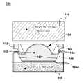
- FIG. 1is a cross-sectional diagram of a fluidic lens according to an embodiment of the present invention.
- FIG. 2is a graph depicting membrane profiles for various radii of curvature for a fluidic lens according to an embodiment of the present invention.
- FIG. 3is a graph illustrating an effect of radius of curvature on strain balancing in a fluidic lens membrane according to an embodiment of the present invention.
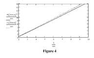
- FIG. 4is a graph illustrating relationships between lens radius and membrane anchor radius using extremes of strain balancing.
- FIG. 5is a graph illustrating membrane profiles for fluidic lenses with pistons of different widths.
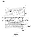
- FIG. 6is a three-dimensional cut-away diagram of a manually adjustable fluidic lens according to an embodiment of the present invention.
- a fluidic lensmay have a transparent window member; a transparent distensible membrane; an inner ring between the transparent window member and the membrane; a layer of liquid stored between the window member, the inner ring and the membrane; and a piston ring disposed such that the membrane is between the piston ring and the inner ring.
- the piston ringmay be adapted to apply a liquid displacement force to the membrane in a direction perpendicular to a plane of an aperture of the inner ring to cause a change in a radius of curvature of the membrane.
- the piston ringmay be characterized by an aperture radius and an annular thickness, wherein the annular thickness is greater than about 20%, 40%, 60%, 80%, or 100% of the annular radius.
- the inner ringmay have a conic frustum shaped inner surface characterized by a half angle.
- the outer ringmay also have a conic frustum shaped outer surface characterized by a half angle that is substantially the same as the half angle for the inner surface of the inner ring.
- An outer edge of the piston ringmay be threaded.
- a surrounding structuremay be adapted to receive the inner ring, membrane and piston ring, the surrounding structure having inner threads that mate with the threads at the outer edge of the piston ring.
- actuated fluidic lens structures described in commonly owned patent applicationsmay be based on a fluid-filled chamber capable of squeezing transparent fluid into a centrally-disposed elastic-membrane-delimited lens. Pressurization of the fluid causes the membranes to bulge, thereby controllably altering the optical power of the lens. The elastic energy of the membranes provides the restoring force which prevails, once the actuating force is diminished.
- Embodiments of the present inventionare related to a family of fluidic optical devices with expanded applicability.
- a fluidic lens 100may comprise a ring shaped piston (piston ring or top ring) 102 that indents the surface of a transparent membrane 104 which separates an inner space filled with a liquid 105 from ambient air. Displacement of the liquid 105 —the liquid being essentially incompressible—causes a central portion of the membrane 104 to bulge outwardly into an energy-minimizing shape. In the case of a thin membrane, the stretching of the membrane is associated with an increase in hydrostatic pressure, for which the energy minimizing shape is a simple spherical cap as seen in FIG. 1 .
- An immovable portion of the membrane 104may be anchored between an Outer Ring (not shown) and an Inner Ring 106 .
- the inner ring 106has an inner surface that provides a lateral boundary for the refractive fluid.
- the Inner Ring 106may include one or more reservoirs in fluid communication with an aperture region of fluidic lens 100 . Examples of such configurations are described, e.g., in US Patent Application Publication 20070030573 and US Patent Application Publication 20070263292, both of which are incorporated herein by reference.
- the inner ring 106may have a conic-frustum inner surface 107 , which forms a lateral boundary of the refractive fluid 105 .
- the top ring 102may have an outer edge with a conic-frustum surface 103 .
- the remaining fluid boundarymay be provided by a Back Window 108 .
- the Back Windowis sometimes referred to as a Round Blank.
- the Membrane 104may extend over an edge of the Back Window 108 as seen in FIG. 1 .
- the Membrane 104may be mechanically secured and hermetically sealed to the Back Window 108 , e.g., by an adhesive.
- the Back Window 108(or at least a portion thereof) may be made of a deformable, e.g., elastomeric or deformable polymer material and may act as a second membrane in a manner similar to the transparent membrane 104 .
- the Fluidic Lens 100may include an optional back Membrane 104 A. Examples of such configurations are described, e.g., in US Patent Application Publication 20070030573 and US Patent Application Publication 20070263292, both of which are incorporated herein by reference.
- the Inner Ring 106may be made of a rigid material, such as a metal or rigid polymer.
- the Inner Ring 106(or at least a portion thereof) may be made of a deformable material, e.g., an elastomer or deformable polymer. If the Inner Ring 106 is deformable, an outer diameter of the Top Ring 102 may be sufficiently large compared to the outer diameter of the Inner Ring 106 that the Top Ring 102 may press upon and deform the Inner Ring 106 , thereby exerting a displacement force on the Liquid 105 .
- the Outer Diameter of the Top Ring 102may be equal to or greater than the Outer diameter of the Inner Ring 106 .
- Inner Ring 106includes a reservoir, some of the Liquid 105 may be expelled from the reservoir into the aperture region of the Fluidic Lens 100 when the Top Ring 102 presses upon the Inner Ring 106 , thereby causing a displacement of the Membrane 104 .
- this front Window 110may serve a number of functions, such as mechanical protection of the elastomeric membrane, wavelength or polarization filtering, additional fixed refraction, etc. Such functions may alternatively be performed by the Back Window 108 .
- FIG. 1Another feature visible in FIG. 1 is the presence of lead screw threads 112 around the outer edges of the Top Ring 102 . These threads 112 may be configured to mate to corresponding threads on an inner edge of a surrounding structure (not shown). When the Top Ring 102 is rotated relative to the surrounding structure (or vice versa), the mating threads on the surrounding structure (not shown) cause the ring to advance or recede against the membrane 104 , thus adjusting the optical power of the fluidic lens 100 .
- the membrane 104should be capable of stretching elastically, should be durable enough to have a lifetime suitable for its application. For example, in a cell phone camera application the membrane 104 should have a lifetime of several years and move than about one million cycles of operation.
- the membrane 104may be made of a silicone-based polymer such as poly(dimethylsiloxane) also known as PDMS or a polyester material such as PET or MylarTM. It is noted that if the fluid 105 and membrane 104 have sufficiently similar refractive indices, or include a suitable optical coating, scattering of light at their interface can be significantly reduced.
- the fluid 105may be silicone oil (e.g., Bis-Phenylpropyl Dimethicone). Additionally, fluid 105 may include fluorinated polymers such as perfluorinated polyether (PFPE) inert fluid.
- PFPEperfluorinated polyether
- the chemical chains of PFPE fluids such as Fomblininclude fluorine, carbon and oxygen and have desirable properties including low vapor pressure, chemical inertness, high thermal stability, good lubricant properties, no flash or fire point, low toxicity, excellent compatibility with metals, plastics and elastomers, good aqueous and non-aqueous solvent resistance, high dielectric properties, low surface tension, good radiation stability and are environmentally acceptable.
- the profile of the membranemay be plotted for various radii of curvature, as in FIG. 2 .
- This profileis applicable as long as radius of the membrane anchor is larger than the outer piston radius (r 1 +w). Although this provides much design latitude, in practice, such a device may need to be operated near the elastic limit of the membrane.
- Rhois fairly constant as the dimensionless radius of curvature varies, except where R approaches r 1 , i.e. the spherical cap approaches a hemispherical shape. This behavior of Rho( ⁇ ) is illustrated in FIG. 3 .
- RhoThe asymptotic value of Rho is given by:
- the asymptotic valuemay be used with less than 2% error for dimensionless radii of curvature down to about 2.
- the other extremeis given by:
- Rho ⁇ ( 1 ) ⁇ 4 ( ⁇ 2 - 4 ) 1 21.651 Eq . ⁇ 4
- the dimensionality of the membrane outer radiusmay first be restored as follows:
- FIG. 4The resulting behavior is shown in FIG. 4 .
- a piston width w of 2 mmhas been assumed for the purposes of example.
- the design of the fluid lensmay be optimized for various objectives.
- the membrane profileis graphically displayed in FIG. 5 in a way that facilitates design trade-off between Top Ring stroke and device footprint.
- fluidic lens membrane profilesare shown for lenses having pistons with different radial widths, thereby illustrating the effect of piston radial width on membrane profile
- the lowest flat portion of each trace in FIG. 5corresponds to the area where the piston face (e.g. the lower portion of the top ring) contacts the membrane.
- a height of zerodesignates a starting level of the membrane just before the Top Ring piston impinges on it.
- the amount of fluid initially contained in the lensis just sufficient to be contained by a flat membrane.
- a similar analysismay be carried out for alternatives where the initial membrane shape is either concave or convex.
- FIG. 6shows the cross section of a manually adjustable fluidic lens 600 in accordance with an alternative embodiment of the present invention.
- the fluidic lens 600additionally includes a knurled Grip 602 , bearing angular markings to be read against a Reference marking 604 .
- the Grip 602is manually rotatable by a user to adjust the optical power of the fluidic lens 600 .
- the Grip 602is mounted in fixed relationship to an Outer Ring 606 .
- the Outer Ring 606is slidably engaged with the Top Ring 102 , so that a pure rotation of the former results in combined rotation and translation of the latter.
- the relative movement between the Top Ring 102 and the Membrane 104is one of pure translation, whereby refractive adjustment is enabled without friction between these components.
- this devicemay be interfaced to the user's optical system by means of lens mounts engaging a Barrel portion 608 of the lens.
- This Barrel 608may feature standardized threads, grooves or flats suitable for mating features of the lens mounts.
- screw threadsmay be provided to engage mounting posts.
- One such threadis shown in FIG. 6 near the Reference marking 604 .
- the force of gravitymay present a challenge to fluidic lens that is not normally associated with conventional lenses.
- the shape of the membrane 104may depend on the orientation of lens with respect to the force of gravity.
- gravityacts on the fluid in a way that causes the fluid to exert a greater fluid pressure on lower regions than on upper regions.
- the pressure differentialgenerally does not present a problem if the Fluidic lens is held substantially horizontal.
- lensesare often used in a vertical or tilted orientation.
- the force of gravity acting on the Liquid 105may lead to asymmetries in the shape of the Membrane 104 .
- the Fluidic lensis oriented such that its optical axis is more or less horizontal, lower portions of the may be more convex more than upper portions.
- Such asymmetriesmay lead to lens aberrations, such as coma.
- the Membrane 104may be pre-tensioned to a degree sufficient to counteract the effect of gravity. Pre-tensioning of the Membrane 104 may also serve to raise a resonant frequency of the Membrane 104 (and, hence of the Fluidic lens 100 ) thereby making them less susceptible to transient aberrations due vibrations or acceleration of the lens.
- the required degree of pre-tensioningmay be determined empirically by measuring optical aberrations or susceptibility to vibration or acceleration as a function of membrane pre-tensioning.
- the pre-tensioning of the Membraneis sufficient to overcome asymmetry in the shape of the Membrane 104 when the Fluidic Lens 100 is in a vertical or tilted orientation.
- the Membrane 104may be pre-tensioned before assembly with the other components of the Fluidic Lens 100 .
- the Membranemay be placed over the Outer Ring 606 .
- a tensionmay be applied to the Membrane 104 in a radially symmetric fashion with respect to an optical axis of the Fluidic Lens 100 .
- the Inner Ring 106may then be placed on the Membrane 104 and the Liquid 105 may be placed in the aperture of the Inner Ring 106 .
- the Back Window 108may then be placed over the Inner Ring 106 with the Liquid 105 retained between the Membrane 104 , the Inner Ring 106 and the Back Window 108 .
- the Back Window 108 and Inner Ring 106may then be pressed into the Outer Ring 606 .
- Adhesivemay optionally be placed on the edge of the Back Window 108 prior to pressing to secure the Membrane 104 in place and retain its pre-tensioned condition.
- the Membranemay be held in place by friction between the Inner Ring 106 and Outer Ring 606 if the fit between the Inner Ring 106 and the Outer Ring 608 is sufficiently tight.
- Adjustable fluidic lenses according to embodiments of the present inventionmay be used in numerous ways by optical researchers, engineers and other users of optical systems. Other uses include telescopes of civilian and military use, medical systems such as used by optometrists to test the vision of patients, etc.
Landscapes
- Physics & Mathematics (AREA)
- General Physics & Mathematics (AREA)
- Optics & Photonics (AREA)
- Mechanical Light Control Or Optical Switches (AREA)
Abstract
Description
Where:
- d=piston stroke
- R=membrane curvature
- r1=lens radius (clear aperture)
- ri=radius of membrane anchor (Inner Ring)
- w=radial width of piston portion of Top Ring
Implementation of Strain Balancing
Claims (23)
Priority Applications (6)
| Application Number | Priority Date | Filing Date | Title |
|---|---|---|---|
| US12/117,625US7697214B2 (en) | 2005-05-14 | 2008-05-08 | Fluidic lens with manually-adjustable focus |
| US12/758,751US7948683B2 (en) | 2006-05-14 | 2010-04-12 | Fluidic lens with manually-adjustable focus |
| US13/113,985US8665527B2 (en) | 2005-05-14 | 2011-05-23 | Fluidic lens with manually-adjustable focus |
| US13/301,492US8605361B2 (en) | 2005-05-14 | 2011-11-21 | Fluidic lens with reduced optical aberration |
| US14/196,976US9442225B2 (en) | 2005-05-14 | 2014-03-04 | Fluidic lens with manually-adjustable focus |
| US15/263,924US10073199B2 (en) | 2005-05-14 | 2016-09-13 | Fluidic lens with adjustable focus |
Applications Claiming Priority (9)
| Application Number | Priority Date | Filing Date | Title |
|---|---|---|---|
| US68063205P | 2005-05-14 | 2005-05-14 | |
| US68307205P | 2005-05-21 | 2005-05-21 | |
| US70382705P | 2005-07-29 | 2005-07-29 | |
| US72338105P | 2005-10-03 | 2005-10-03 | |
| US74718106P | 2006-05-12 | 2006-05-12 | |
| US11/383,216US7646544B2 (en) | 2005-05-14 | 2006-05-14 | Fluidic optical devices |
| US91673907P | 2007-05-08 | 2007-05-08 | |
| US11/747,845US7672059B2 (en) | 2000-10-20 | 2007-05-11 | Fluidic lens with electrostatic actuation |
| US12/117,625US7697214B2 (en) | 2005-05-14 | 2008-05-08 | Fluidic lens with manually-adjustable focus |
Related Parent Applications (4)
| Application Number | Title | Priority Date | Filing Date |
|---|---|---|---|
| US11/383,216Continuation-In-PartUS7646544B2 (en) | 2000-10-20 | 2006-05-14 | Fluidic optical devices |
| US11/747,845Continuation-In-PartUS7672059B2 (en) | 2000-10-20 | 2007-05-11 | Fluidic lens with electrostatic actuation |
| US11/747,845ContinuationUS7672059B2 (en) | 2000-10-20 | 2007-05-11 | Fluidic lens with electrostatic actuation |
| US12/758,751ContinuationUS7948683B2 (en) | 2005-05-14 | 2010-04-12 | Fluidic lens with manually-adjustable focus |
Related Child Applications (3)
| Application Number | Title | Priority Date | Filing Date |
|---|---|---|---|
| US12/706,637Continuation-In-PartUS8064142B2 (en) | 2005-05-14 | 2010-02-16 | Fluidic lens with reduced optical aberration |
| US12/758,751ContinuationUS7948683B2 (en) | 2005-05-14 | 2010-04-12 | Fluidic lens with manually-adjustable focus |
| US13/113,985ContinuationUS8665527B2 (en) | 2005-05-14 | 2011-05-23 | Fluidic lens with manually-adjustable focus |
Publications (2)
| Publication Number | Publication Date |
|---|---|
| US20080285143A1 US20080285143A1 (en) | 2008-11-20 |
| US7697214B2true US7697214B2 (en) | 2010-04-13 |
Family
ID=46330265
Family Applications (4)
| Application Number | Title | Priority Date | Filing Date |
|---|---|---|---|
| US12/117,625Active - ReinstatedUS7697214B2 (en) | 2005-05-14 | 2008-05-08 | Fluidic lens with manually-adjustable focus |
| US13/113,985Active - Reinstated2027-03-20US8665527B2 (en) | 2005-05-14 | 2011-05-23 | Fluidic lens with manually-adjustable focus |
| US14/196,976ActiveUS9442225B2 (en) | 2005-05-14 | 2014-03-04 | Fluidic lens with manually-adjustable focus |
| US15/263,924ActiveUS10073199B2 (en) | 2005-05-14 | 2016-09-13 | Fluidic lens with adjustable focus |
Family Applications After (3)
| Application Number | Title | Priority Date | Filing Date |
|---|---|---|---|
| US13/113,985Active - Reinstated2027-03-20US8665527B2 (en) | 2005-05-14 | 2011-05-23 | Fluidic lens with manually-adjustable focus |
| US14/196,976ActiveUS9442225B2 (en) | 2005-05-14 | 2014-03-04 | Fluidic lens with manually-adjustable focus |
| US15/263,924ActiveUS10073199B2 (en) | 2005-05-14 | 2016-09-13 | Fluidic lens with adjustable focus |
Country Status (1)
| Country | Link |
|---|---|
| US (4) | US7697214B2 (en) |
Cited By (14)
| Publication number | Priority date | Publication date | Assignee | Title |
|---|---|---|---|---|
| US20100045930A1 (en)* | 2006-10-23 | 2010-02-25 | Joshua David Silver | Variable focus lens and spectacles |
| US20100128357A1 (en)* | 2008-11-17 | 2010-05-27 | Holochip Corporation | Fluidic stabilized focus device |
| US20100232031A1 (en)* | 2006-05-14 | 2010-09-16 | Holochip Corporation | Fluidic lens with manually-adjustable focus |
| US20100232161A1 (en)* | 2009-03-13 | 2010-09-16 | Manuel Aschwanden | Lens Assembly Apparatus And Method |
| US20110007161A1 (en)* | 2005-05-14 | 2011-01-13 | Holochip Corporation | Fluidic optical devices |
| US20110096411A1 (en)* | 2007-02-12 | 2011-04-28 | Polight As | Flexible lens assembly with variable focal length |
| US20110267703A1 (en)* | 2005-05-14 | 2011-11-03 | Holochip Corporation | Fluidic lens with manually-adjustable focus |
| US8441737B2 (en) | 2008-04-10 | 2013-05-14 | Adlens, Ltd. | Variable focus lens and spectacles |
| US8632217B2 (en)* | 2011-08-09 | 2014-01-21 | Asia Vital Components Co., Ltd. | Light head structure with adjustable focal length and lighting device thereof |
| US8797654B2 (en) | 2008-08-08 | 2014-08-05 | Optotune Ag | Electroactive optical device |
| US8947784B2 (en) | 2010-10-26 | 2015-02-03 | Optotune Ag | Variable focus lens having two liquid chambers |
| US8944647B2 (en) | 2010-09-02 | 2015-02-03 | Optotune Ag | Illumination source with variable divergence |
| US9164202B2 (en) | 2010-02-16 | 2015-10-20 | Holochip Corporation | Adaptive optical devices with controllable focal power and aspheric shape |
| US9535264B2 (en) | 2012-07-13 | 2017-01-03 | Adlens Beacon, Inc. | Fluid lenses, lens blanks, and methods of manufacturing the same |
Families Citing this family (37)
| Publication number | Priority date | Publication date | Assignee | Title |
|---|---|---|---|---|
| US7672059B2 (en)* | 2000-10-20 | 2010-03-02 | Holochip Corporation | Fluidic lens with electrostatic actuation |
| US8064142B2 (en) | 2005-05-14 | 2011-11-22 | Holochip Corporation | Fluidic lens with reduced optical aberration |
| EP2214036A1 (en)* | 2009-01-28 | 2010-08-04 | BAE Systems PLC | Fluidic lens |
| US20100208194A1 (en) | 2009-02-13 | 2010-08-19 | Amitava Gupta | Variable focus liquid filled lens apparatus |
| US8087778B2 (en) | 2009-02-13 | 2012-01-03 | Adlens Beacon, Inc. | Variable focus liquid filled lens mechanism |
| US8659835B2 (en)* | 2009-03-13 | 2014-02-25 | Optotune Ag | Lens systems and method |
| US8154810B2 (en)* | 2009-07-16 | 2012-04-10 | Microscan Systems, Inc. | Optical assemblies for adjusting working distance and field of view in an imaging system |
| KR101680300B1 (en)* | 2009-08-31 | 2016-11-28 | 삼성전자주식회사 | Liquid lens and method for manufacturing the same |
| KR101675130B1 (en)* | 2009-09-03 | 2016-11-10 | 삼성전자주식회사 | Fluidic lens |
| US8817381B2 (en) | 2009-10-13 | 2014-08-26 | Adlens Beacon, Inc. | Full field membrane design for non-round liquid lens assemblies |
| US8414121B2 (en)* | 2009-10-13 | 2013-04-09 | Adlens Beacon, Inc. | Non-round fluid filled lens optic |
| US8136942B2 (en) | 2009-10-14 | 2012-03-20 | Adlens Beacon, Inc. | Aspheric fluid filled lens optic |
| US8708486B2 (en) | 2009-10-15 | 2014-04-29 | Adlens Beacon, Inc. | Fluid filled lenses and mechanisms of inflation thereof |
| US8353593B2 (en) | 2009-10-15 | 2013-01-15 | Adlens Beacon, Inc. | Hinge mechanism for a fluid filled lens assembly |
| US8596781B2 (en)* | 2009-10-15 | 2013-12-03 | Adlens Beacon, Inc. | Fluid filled lens reservoir system and manufacturing method of the reservoir system |
| US9036264B2 (en) | 2010-08-12 | 2015-05-19 | Adlens Beacon, Inc. | Fluid-filled lenses and their ophthalmic applications |
| KR101912092B1 (en) | 2010-10-05 | 2018-10-26 | 삼성전자 주식회사 | Fluidic lens |
| WO2012051154A1 (en) | 2010-10-11 | 2012-04-19 | Lisa Nibauer | Non powered concepts for a wire frame of fluid filled lenses |
| USD665009S1 (en) | 2010-10-14 | 2012-08-07 | Adlens Beacon, Inc. | Spectacles frame |
| KR101912093B1 (en) | 2010-10-29 | 2018-10-26 | 삼성전자 주식회사 | Optical apparatus |
| ES2634438T3 (en) | 2010-11-10 | 2017-09-27 | Adlens Beacon, Inc. | Fluid-filled lenses and their drive systems |
| EP2682814A1 (en)* | 2012-07-03 | 2014-01-08 | poLight AS | Low profile auto focus device and method thereof for an optical imaging system |
| EP2860555A1 (en) | 2013-10-08 | 2015-04-15 | Optotune AG | Tunable lens |
| KR102619638B1 (en) | 2016-01-28 | 2023-12-29 | 엘지이노텍 주식회사 | Lens module and Camera module including the same |
| KR20180094615A (en)* | 2017-02-16 | 2018-08-24 | 엘지이노텍 주식회사 | Liquid lens and camera module module including the same |
| US10253983B1 (en) | 2017-03-28 | 2019-04-09 | Randy Wolf | Fire-starting canteen |
| CN109839713B (en)* | 2017-11-29 | 2021-12-03 | 宁波舜宇光电信息有限公司 | Zoom assembly, lens assembly and camera module |
| KR102858869B1 (en) | 2017-12-10 | 2025-09-11 | 매직 립, 인코포레이티드 | Anti-reflective coatings on optical waveguides |
| CN111712751B (en) | 2017-12-20 | 2022-11-01 | 奇跃公司 | Insert for augmented reality viewing apparatus |
| GB201800930D0 (en) | 2018-01-19 | 2018-03-07 | Adlens Ltd | Improvements in or relating to variable focusing power optical devices |
| US11204491B2 (en)* | 2018-05-30 | 2021-12-21 | Magic Leap, Inc. | Compact variable focus configurations |
| CN112585581B (en) | 2018-07-10 | 2024-10-18 | 奇跃公司 | Thread weaving for cross-ISA procedure calls |
| BE1026500B1 (en) | 2018-07-31 | 2020-03-02 | Schreder Sa | Lighting device with adjustable light distribution |
| CN110161674A (en)* | 2019-04-30 | 2019-08-23 | 南京邮电大学 | Liquid lens |
| KR20210078420A (en)* | 2019-12-17 | 2021-06-28 | 옵토튠 컨슈머 아게 | Liquid lens with a laterally arranged pump portion |
| KR20220121722A (en) | 2021-02-25 | 2022-09-01 | 옵토투네 아게 | Liquid for tunable optics |
| US20240076453A1 (en) | 2022-08-19 | 2024-03-07 | Optotune Switzerland Ag | Liquids for tunable optical devices |
Citations (35)
| Publication number | Priority date | Publication date | Assignee | Title |
|---|---|---|---|---|
| US696788A (en) | 1901-02-25 | 1902-04-01 | Clile C Allen | Optical objective. |
| US2300251A (en)* | 1941-01-23 | 1942-10-27 | Bausch & Lomb | Variable focus lens |
| US2504039A (en)* | 1946-05-01 | 1950-04-11 | O'leary Russell | Optical instrument having adjustable fluid prism means |
| US4261655A (en) | 1978-01-09 | 1981-04-14 | Honigsbaum Richard F | Biomechanically focused eyeglasses |
| US4444471A (en) | 1982-03-12 | 1984-04-24 | Polaroid Corporation | Variable focus lens system employing elastomeric lens |
| US4466706A (en) | 1982-03-10 | 1984-08-21 | Lamothe Ii Frederick H | Optical fluid lens |
| US4514048A (en) | 1981-08-17 | 1985-04-30 | Polaroid Corporation | Variable focus elastomeric lens system |
| US4783155A (en)* | 1983-10-17 | 1988-11-08 | Canon Kabushiki Kaisha | Optical device with variably shaped optical surface and a method for varying the focal length |
| US4784479A (en) | 1984-05-30 | 1988-11-15 | Canon Kabushiki Kaisha | Varifocal optical system |
| US4890903A (en) | 1985-11-05 | 1990-01-02 | Michel Treisman | Suspension system for a flexible optical membrane |
| US5672001A (en) | 1994-10-13 | 1997-09-30 | Robert Bosch Gmbh | Vehicle headlamp |
| US5774273A (en) | 1996-08-23 | 1998-06-30 | Vari-Lite, Inc. | Variable-geometry liquid-filled lens apparatus and method for controlling the energy distribution of a light beam |
| WO1999018456A1 (en) | 1997-10-08 | 1999-04-15 | Universite Joseph Fourier | Lens with variable focus |
| US5973852A (en) | 1998-03-26 | 1999-10-26 | The United States Of America As Represented By The Secretary Of The Air Force | Variable power fluid lens |
| US6288767B1 (en) | 1996-06-07 | 2001-09-11 | Olympus Optical Company, Ltd | Imaging optical system |
| US6542309B2 (en)* | 2001-06-29 | 2003-04-01 | The Boeing Company | Flexible lens |
| US6618208B1 (en) | 1998-03-19 | 2003-09-09 | Joshua David Silver | Variable focus optical devices |
| US20040240076A1 (en)* | 2001-01-02 | 2004-12-02 | Silver Joshua D. | Variable focus optical apparatus |
| US20040262645A1 (en) | 2001-05-18 | 2004-12-30 | Corporation For National Research Initiatives | Radio frequency microelectromechanical systems (MEMS) devices on low-temperature co-fired ceramic (LTCC) substrates |
| US6860601B2 (en)* | 2002-02-06 | 2005-03-01 | John H. Shadduck | Adaptive optic lens system and method of use |
| US20060126190A1 (en) | 2004-11-24 | 2006-06-15 | Varioptic S.A. | Lens of variable focal length |
| US7068439B2 (en) | 2002-11-20 | 2006-06-27 | Powervision, Inc. | Lens system and method for power adjustment |
| US7072086B2 (en) | 2001-10-19 | 2006-07-04 | Batchko Robert G | Digital focus lens system |
| US20060164731A1 (en) | 2005-01-21 | 2006-07-27 | Shin-Tson Wu | Variable focus liquid lens |
| US20070030573A1 (en) | 2005-05-14 | 2007-02-08 | Holochip Corporation | Fluidic optical devices |
| US7218430B2 (en) | 2000-10-20 | 2007-05-15 | Robert G Batchko | Combinatorial optical processor |
| US20070211207A1 (en) | 2004-03-31 | 2007-09-13 | Yuhwa Lo | Fluidic Adaptive Lens |
| US20070263293A1 (en) | 2000-10-20 | 2007-11-15 | Holochip Corporation | Fluidic lens with electrostatic actuation |
| US7359124B1 (en) | 2004-04-30 | 2008-04-15 | Louisiana Tech University Research Foundation As A Division Of The Louisiana Tech University Foundation | Wide-angle variable focal length lens system |
| US7369723B1 (en) | 2001-11-09 | 2008-05-06 | The Charles Stark Draper Laboratory, Inc. | High speed piezoelectric optical system with tunable focal length |
| US7369321B1 (en) | 2007-01-16 | 2008-05-06 | University Of Central Florida Research Foundation, Inc. | Variable-focus liquid lens |
| US7374301B1 (en) | 2005-02-20 | 2008-05-20 | Douglas Evan Simmers | Stretched membrane device |
| US7453646B2 (en) | 2004-03-31 | 2008-11-18 | The Regents Of The University Of California | Fluidic adaptive lens systems and methods |
| US20090021823A1 (en) | 2007-05-31 | 2009-01-22 | Artificial Muscle, Inc. | Optical systems employing compliant electroactive materials |
| US20090040361A1 (en) | 2007-08-08 | 2009-02-12 | Artificial Muscle, Inc. | Optical lens image stabilization systems |
Family Cites Families (53)
| Publication number | Priority date | Publication date | Assignee | Title |
|---|---|---|---|---|
| US3161718A (en) | 1961-07-12 | 1964-12-15 | William Kurasch | Variable power fluid lens |
| GB1327503A (en) | 1971-02-05 | 1973-08-22 | Bosch Gmbh Robert | Optical lenses |
| US4289379A (en) | 1977-04-27 | 1981-09-15 | Quantel S.A. | Optical system having a variable focal length |
| US4802746A (en) | 1985-02-26 | 1989-02-07 | Canon Kabushiki Kaisha | Variable-focus optical element and focus detecting device utilizing the same |
| JPS62276503A (en) | 1986-05-26 | 1987-12-01 | Canon Inc | variable focus optics |
| IL83179A0 (en)* | 1987-07-14 | 1987-12-31 | Daniel Barnea | Variable lens |
| JPH01166004A (en) | 1987-12-22 | 1989-06-29 | Fuji Photo Film Co Ltd | Optical element |
| JPH01166003A (en) | 1987-12-22 | 1989-06-29 | Fuji Photo Film Co Ltd | Optical element |
| US5138494A (en) | 1990-05-07 | 1992-08-11 | Stephen Kurtin | Variable focal length lens |
| EP0890118B1 (en) | 1996-03-26 | 2000-06-14 | MANNESMANN Aktiengesellschaft | Opto-electronic imaging system for industrial applications |
| JP3400270B2 (en) | 1996-11-08 | 2003-04-28 | 株式会社デンソー | Laminated piezoelectric actuator and variable focus lens device |
| JPH1166004A (en) | 1997-08-12 | 1999-03-09 | Hideo Takeda | Early detecting method for illegal use of password |
| JPH1166003A (en) | 1997-08-26 | 1999-03-09 | P I Ii:Kk | Control method for job support system and job support system |
| JPH11133210A (en) | 1997-10-30 | 1999-05-21 | Denso Corp | Variable focus lens |
| US6130705A (en) | 1998-07-10 | 2000-10-10 | Recon/Optical, Inc. | Autonomous electro-optical framing camera system with constant ground resolution, unmanned airborne vehicle therefor, and methods of use |
| JP4144079B2 (en) | 1998-09-04 | 2008-09-03 | 株式会社デンソー | Variable focus lens |
| US6747806B2 (en) | 2001-04-19 | 2004-06-08 | Creo Srl | Method for controlling light beam using adaptive micro-lens |
| US20040082993A1 (en) | 2002-10-25 | 2004-04-29 | Randall Woods | Capsular intraocular lens implant having a refractive liquid therein |
| WO2004087178A1 (en) | 2003-03-31 | 2004-10-14 | Alimentary Health Limited | A formulation comprising a bacterial strain |
| JP2005092175A (en) | 2003-08-08 | 2005-04-07 | Olympus Corp | Variable optical-property optical element |
| JP2005062632A (en) | 2003-08-19 | 2005-03-10 | Konica Minolta Opto Inc | Lens system |
| GB0407240D0 (en) | 2004-03-30 | 2004-05-05 | Koninkl Philips Electronics Nv | Controllable optical lens |
| GB0407414D0 (en) | 2004-04-01 | 2004-05-05 | 1 Ltd | Variable focal length lens |
| JP4530163B2 (en) | 2005-03-31 | 2010-08-25 | セイコープレシジョン株式会社 | Focus adjustment device and imaging device |
| US7948683B2 (en)* | 2006-05-14 | 2011-05-24 | Holochip Corporation | Fluidic lens with manually-adjustable focus |
| US7697214B2 (en) | 2005-05-14 | 2010-04-13 | Holochip Corporation | Fluidic lens with manually-adjustable focus |
| US8064142B2 (en) | 2005-05-14 | 2011-11-22 | Holochip Corporation | Fluidic lens with reduced optical aberration |
| US8503875B2 (en) | 2008-11-17 | 2013-08-06 | Holochip Corporation | Fluidic viewfinder device |
| WO2007017089A1 (en) | 2005-07-25 | 2007-02-15 | Carl Zeiss Smt Ag | Projection objective of a microlithographic projection exposure apparatus |
| US7368210B2 (en) | 2005-07-28 | 2008-05-06 | Xerox Corporation | Photoreceptor layer having thiophosphate lubricants |
| JP4697786B2 (en) | 2005-08-23 | 2011-06-08 | セイコープレシジョン株式会社 | Variable focus lens, and focus adjustment device and imaging device using the same |
| US7889316B2 (en) | 2006-05-15 | 2011-02-15 | Asml Netherlands B.V. | Method for patterning a radiation beam, patterning device for patterning a radiation beam |
| JP4209936B2 (en) | 2006-08-10 | 2009-01-14 | パナソニック株式会社 | Variable focus lens device |
| KR20080043106A (en) | 2006-11-13 | 2008-05-16 | 삼성전자주식회사 | Optical lens and manufacturing method thereof |
| US8027096B2 (en) | 2006-12-15 | 2011-09-27 | Hand Held Products, Inc. | Focus module and components with actuator polymer control |
| US7813047B2 (en) | 2006-12-15 | 2010-10-12 | Hand Held Products, Inc. | Apparatus and method comprising deformable lens element |
| JP5046740B2 (en) | 2007-05-14 | 2012-10-10 | キヤノン株式会社 | Zoom lens and imaging apparatus having the same |
| US20090003838A1 (en) | 2007-06-27 | 2009-01-01 | Lucent Technologies Incorporated | Optical Data Communication System Having Reduced Pulse Distortion and Method of Operating the Same |
| EP2034338A1 (en) | 2007-08-11 | 2009-03-11 | ETH Zurich | Liquid Lens System |
| JP4442682B2 (en) | 2007-11-27 | 2010-03-31 | ソニー株式会社 | Optical element |
| KR20100112631A (en) | 2008-01-30 | 2010-10-19 | 유니챰 가부시키가이샤 | Method of manufacturing diapers |
| US20090195882A1 (en) | 2008-02-05 | 2009-08-06 | Bolle Cristian A | Mechanical lenses |
| GB0806561D0 (en)* | 2008-04-10 | 2008-05-14 | Adlens Ltd | Variable focus lens and spectacles |
| US8064132B1 (en) | 2008-06-18 | 2011-11-22 | Vectronix, Inc. | Binoculars with adaptive reticle display and associated methods |
| WO2010015093A1 (en) | 2008-08-08 | 2010-02-11 | Optotune Ag | Electroactive optical device |
| FR2938349B1 (en) | 2008-11-07 | 2011-04-15 | Commissariat Energie Atomique | OPTICAL DEVICE WITH DEFORMABLE MEMBRANE WITH IMPROVED ACTUATION |
| KR101573504B1 (en) | 2008-11-10 | 2015-12-01 | 삼성전자 주식회사 | Micro shutter device and manufacturing method thereof |
| JP5710466B2 (en) | 2009-02-20 | 2015-04-30 | 株式会社オイレー企画 | Bifocal lenses and bifocal glasses |
| US8659835B2 (en) | 2009-03-13 | 2014-02-25 | Optotune Ag | Lens systems and method |
| US8699141B2 (en) | 2009-03-13 | 2014-04-15 | Knowles Electronics, Llc | Lens assembly apparatus and method |
| US9164202B2 (en) | 2010-02-16 | 2015-10-20 | Holochip Corporation | Adaptive optical devices with controllable focal power and aspheric shape |
| US8038066B2 (en) | 2009-04-29 | 2011-10-18 | Hand Held Products, Inc. | Laser scanner with deformable lens |
| EP2239600A1 (en) | 2010-06-02 | 2010-10-13 | Optotune AG | Adjustable optical lens |
- 2008
- 2008-05-08USUS12/117,625patent/US7697214B2/enactiveActive - Reinstated
- 2011
- 2011-05-23USUS13/113,985patent/US8665527B2/enactiveActive - Reinstated
- 2014
- 2014-03-04USUS14/196,976patent/US9442225B2/enactiveActive
- 2016
- 2016-09-13USUS15/263,924patent/US10073199B2/enactiveActive
Patent Citations (41)
| Publication number | Priority date | Publication date | Assignee | Title |
|---|---|---|---|---|
| US696788A (en) | 1901-02-25 | 1902-04-01 | Clile C Allen | Optical objective. |
| US2300251A (en)* | 1941-01-23 | 1942-10-27 | Bausch & Lomb | Variable focus lens |
| US2504039A (en)* | 1946-05-01 | 1950-04-11 | O'leary Russell | Optical instrument having adjustable fluid prism means |
| US4261655A (en) | 1978-01-09 | 1981-04-14 | Honigsbaum Richard F | Biomechanically focused eyeglasses |
| US4514048A (en) | 1981-08-17 | 1985-04-30 | Polaroid Corporation | Variable focus elastomeric lens system |
| US4466706A (en) | 1982-03-10 | 1984-08-21 | Lamothe Ii Frederick H | Optical fluid lens |
| US4444471A (en) | 1982-03-12 | 1984-04-24 | Polaroid Corporation | Variable focus lens system employing elastomeric lens |
| US4783155A (en)* | 1983-10-17 | 1988-11-08 | Canon Kabushiki Kaisha | Optical device with variably shaped optical surface and a method for varying the focal length |
| US4784479A (en) | 1984-05-30 | 1988-11-15 | Canon Kabushiki Kaisha | Varifocal optical system |
| US4890903A (en) | 1985-11-05 | 1990-01-02 | Michel Treisman | Suspension system for a flexible optical membrane |
| US5672001A (en) | 1994-10-13 | 1997-09-30 | Robert Bosch Gmbh | Vehicle headlamp |
| US6288767B1 (en) | 1996-06-07 | 2001-09-11 | Olympus Optical Company, Ltd | Imaging optical system |
| US5774273A (en) | 1996-08-23 | 1998-06-30 | Vari-Lite, Inc. | Variable-geometry liquid-filled lens apparatus and method for controlling the energy distribution of a light beam |
| WO1999018456A1 (en) | 1997-10-08 | 1999-04-15 | Universite Joseph Fourier | Lens with variable focus |
| US6369954B1 (en) | 1997-10-08 | 2002-04-09 | Universite Joseph Fourier | Lens with variable focus |
| US6618208B1 (en) | 1998-03-19 | 2003-09-09 | Joshua David Silver | Variable focus optical devices |
| US20060077562A1 (en)* | 1998-03-19 | 2006-04-13 | Joshua David Silver | Variable focus optical devices |
| US5973852A (en) | 1998-03-26 | 1999-10-26 | The United States Of America As Represented By The Secretary Of The Air Force | Variable power fluid lens |
| US7218430B2 (en) | 2000-10-20 | 2007-05-15 | Robert G Batchko | Combinatorial optical processor |
| US20070263293A1 (en) | 2000-10-20 | 2007-11-15 | Holochip Corporation | Fluidic lens with electrostatic actuation |
| US7218429B2 (en) | 2000-10-20 | 2007-05-15 | Batchko Robert G | Digital focus lens system |
| US20040240076A1 (en)* | 2001-01-02 | 2004-12-02 | Silver Joshua D. | Variable focus optical apparatus |
| US20040262645A1 (en) | 2001-05-18 | 2004-12-30 | Corporation For National Research Initiatives | Radio frequency microelectromechanical systems (MEMS) devices on low-temperature co-fired ceramic (LTCC) substrates |
| US6542309B2 (en)* | 2001-06-29 | 2003-04-01 | The Boeing Company | Flexible lens |
| US7072086B2 (en) | 2001-10-19 | 2006-07-04 | Batchko Robert G | Digital focus lens system |
| US7369723B1 (en) | 2001-11-09 | 2008-05-06 | The Charles Stark Draper Laboratory, Inc. | High speed piezoelectric optical system with tunable focal length |
| US6860601B2 (en)* | 2002-02-06 | 2005-03-01 | John H. Shadduck | Adaptive optic lens system and method of use |
| US7068439B2 (en) | 2002-11-20 | 2006-06-27 | Powervision, Inc. | Lens system and method for power adjustment |
| US20070211207A1 (en) | 2004-03-31 | 2007-09-13 | Yuhwa Lo | Fluidic Adaptive Lens |
| US7453646B2 (en) | 2004-03-31 | 2008-11-18 | The Regents Of The University Of California | Fluidic adaptive lens systems and methods |
| US7440193B2 (en) | 2004-04-30 | 2008-10-21 | Gunasekaran R Alfred | Wide-angle variable focal length lens system |
| US7359124B1 (en) | 2004-04-30 | 2008-04-15 | Louisiana Tech University Research Foundation As A Division Of The Louisiana Tech University Foundation | Wide-angle variable focal length lens system |
| US20060126190A1 (en) | 2004-11-24 | 2006-06-15 | Varioptic S.A. | Lens of variable focal length |
| US20060164731A1 (en) | 2005-01-21 | 2006-07-27 | Shin-Tson Wu | Variable focus liquid lens |
| US7142369B2 (en) | 2005-01-21 | 2006-11-28 | Research Foundation Of The University Of Central Florida, Inc. | Variable focus liquid lens |
| US7374301B1 (en) | 2005-02-20 | 2008-05-20 | Douglas Evan Simmers | Stretched membrane device |
| US20070030573A1 (en) | 2005-05-14 | 2007-02-08 | Holochip Corporation | Fluidic optical devices |
| US20090052049A1 (en)* | 2005-05-14 | 2009-02-26 | Holochip Corporation | Fluidic optical devices |
| US7369321B1 (en) | 2007-01-16 | 2008-05-06 | University Of Central Florida Research Foundation, Inc. | Variable-focus liquid lens |
| US20090021823A1 (en) | 2007-05-31 | 2009-01-22 | Artificial Muscle, Inc. | Optical systems employing compliant electroactive materials |
| US20090040361A1 (en) | 2007-08-08 | 2009-02-12 | Artificial Muscle, Inc. | Optical lens image stabilization systems |
Non-Patent Citations (26)
| Title |
|---|
| Ex parte Quayle Action dated Aug. 20, 2009 for U.S. Appl. No. 11/928,076 entitled "Fluidic Optical Devices". |
| Final Office Action dated Jan. 22, 2009 for U.S. Appl. No. 11/383,216, 17 pages. |
| Hongwen Ren et al. "Variable-Focus Liquid Lens By Changing Aperature", Applied Physics Letters, vol. 86, No. 21107, May 17, 2005, p. 211107-1-211107-3. |
| International Search Report and Written Opinion of the International Searching Authority dated Aug. 8, 2008-International Patent Application No. PCT/US08/63122, 9 pages. |
| International Search Report and Written Opinion of the International Searching Authority for the International application No. PCT/US08/63107 dated Aug. 4, 2008, 7 pages. |
| J. Chen et al., "Variable-Focusing Microlens with Microfluidic Chip", J. Micromech.Microeng. 14, p. 675-680, 2004. |
| Non-final Office Action dated Sep. 21, 2009 for U.S. Appl. No. 11/928,376 entitled "Fluidic Optical Devices". |
| Notice of Allowance and Fee(s) Due dated Apr. 23, 2009 for U.S. Appl. No. 11/928,076, 7 pages. |
| Notice of Allowance and Fee(s) Due dated Apr. 9, 2009 for U.S. Appl. No. 11/383,216, 6 pages. |
| Notice of Allowance dated Aug. 13, 2009 for U.S. Appl. No. 11/928,216 entitled "Fluidic Optical Devices". |
| Notice of Allowance dated Aug. 28, 2009 for U.S. Appl. No. 11/383,216 entitled "Fluidic Optical Devices". |
| Notice of Allowance dated Jul. 9, 2009 for U.S. Appl. No. 11/747,845 entitled "Fluidic Lens With Electrostatic Actuation". |
| Notice of Allowance dated Mar. 10, 2009 for U.S. Appl. No. 11/747,845. |
| Office Action dated Jul. 23, 2008 for U.S. Appl. No. 11/747,845, 9 pages. |
| Office Action dated Jun. 12, 2008 for U.S. Appl. No. 11/383,216, 22 pages. |
| Office Action dated Mar. 5, 2009 for U.S. Appl. No. 11/928,216. |
| Office Action dated Oct. 22, 2008 for U.S. Appl. No. 11/928,076, 8 pages. |
| S. Perichon et al. "Stretchable Gold Conductors on Elastomeric Substrate", Applied. Physics. Letter, vol. 82, No. 15, p. 2404-2406, Apr. 14, 2003. |
| U.S. Appl. No. 60/242,395, to Batchko, entitled "Combinatorial Optics" filed Oct. 20, 2000. |
| U.S. Appl. No. 60/395,849, to Batchko, entitled "Digital Focus Lens System" filed Jul. 11, 2002. |
| U.S. Appl. No. 60/680,632, filed May 14, 2005. |
| U.S. Appl. No. 60/683,072, filed May 21, 2005. |
| U.S. Appl. No. 60/703,827, filed Jul. 29, 2005. |
| U.S. Appl. No. 60/723,381, filed Oct. 3, 2005. |
| U.S. Appl. No. 60/747,181, filed May 12, 2006. |
| U.S. Appl. No. 60/916,739, filed May 8, 2007. |
Cited By (25)
| Publication number | Priority date | Publication date | Assignee | Title |
|---|---|---|---|---|
| US10073199B2 (en) | 2005-05-14 | 2018-09-11 | Holochip Corporation | Fluidic lens with adjustable focus |
| US9442225B2 (en) | 2005-05-14 | 2016-09-13 | Holochip Corporation | Fluidic lens with manually-adjustable focus |
| US20110007161A1 (en)* | 2005-05-14 | 2011-01-13 | Holochip Corporation | Fluidic optical devices |
| US20110267703A1 (en)* | 2005-05-14 | 2011-11-03 | Holochip Corporation | Fluidic lens with manually-adjustable focus |
| US8665527B2 (en)* | 2005-05-14 | 2014-03-04 | Holochip Corporation | Fluidic lens with manually-adjustable focus |
| US20100232031A1 (en)* | 2006-05-14 | 2010-09-16 | Holochip Corporation | Fluidic lens with manually-adjustable focus |
| US7948683B2 (en)* | 2006-05-14 | 2011-05-24 | Holochip Corporation | Fluidic lens with manually-adjustable focus |
| US20100045930A1 (en)* | 2006-10-23 | 2010-02-25 | Joshua David Silver | Variable focus lens and spectacles |
| US20110096411A1 (en)* | 2007-02-12 | 2011-04-28 | Polight As | Flexible lens assembly with variable focal length |
| US8390939B2 (en)* | 2007-02-12 | 2013-03-05 | Polight As | Flexible lens assembly with variable focal length |
| US8441737B2 (en) | 2008-04-10 | 2013-05-14 | Adlens, Ltd. | Variable focus lens and spectacles |
| US8797654B2 (en) | 2008-08-08 | 2014-08-05 | Optotune Ag | Electroactive optical device |
| US8559115B2 (en)* | 2008-11-17 | 2013-10-15 | Holochip Corporation | Fluidic stabilized focus device |
| US8503875B2 (en)* | 2008-11-17 | 2013-08-06 | Holochip Corporation | Fluidic viewfinder device |
| US20100128358A1 (en)* | 2008-11-17 | 2010-05-27 | Holochip Corporation | Fluidic viewfinder device |
| US20100128357A1 (en)* | 2008-11-17 | 2010-05-27 | Holochip Corporation | Fluidic stabilized focus device |
| US8699141B2 (en)* | 2009-03-13 | 2014-04-15 | Knowles Electronics, Llc | Lens assembly apparatus and method |
| US20100232161A1 (en)* | 2009-03-13 | 2010-09-16 | Manuel Aschwanden | Lens Assembly Apparatus And Method |
| US10401537B2 (en) | 2009-04-20 | 2019-09-03 | Holochip Corporation | Adaptive optical devices with controllable focal power and aspheric shape |
| US9164202B2 (en) | 2010-02-16 | 2015-10-20 | Holochip Corporation | Adaptive optical devices with controllable focal power and aspheric shape |
| US9500782B2 (en) | 2010-02-16 | 2016-11-22 | Holochip Corporation | Adaptive optical devices with controllable focal power and aspheric shape |
| US8944647B2 (en) | 2010-09-02 | 2015-02-03 | Optotune Ag | Illumination source with variable divergence |
| US8947784B2 (en) | 2010-10-26 | 2015-02-03 | Optotune Ag | Variable focus lens having two liquid chambers |
| US8632217B2 (en)* | 2011-08-09 | 2014-01-21 | Asia Vital Components Co., Ltd. | Light head structure with adjustable focal length and lighting device thereof |
| US9535264B2 (en) | 2012-07-13 | 2017-01-03 | Adlens Beacon, Inc. | Fluid lenses, lens blanks, and methods of manufacturing the same |
Also Published As
| Publication number | Publication date |
|---|---|
| US20140313590A1 (en) | 2014-10-23 |
| US20170068020A1 (en) | 2017-03-09 |
| US10073199B2 (en) | 2018-09-11 |
| US20110267703A1 (en) | 2011-11-03 |
| US9442225B2 (en) | 2016-09-13 |
| US8665527B2 (en) | 2014-03-04 |
| US20080285143A1 (en) | 2008-11-20 |
Similar Documents
| Publication | Publication Date | Title |
|---|---|---|
| US7697214B2 (en) | Fluidic lens with manually-adjustable focus | |
| US7948683B2 (en) | Fluidic lens with manually-adjustable focus | |
| EP2162769A1 (en) | Fluidic lens with manually-adjustable focus | |
| US8254034B1 (en) | Fluidic adaptive lens with a lens membrane having suppressed fluid permeability | |
| US7646544B2 (en) | Fluidic optical devices | |
| Agarwal et al. | Polymer-based variable focal length microlens system | |
| JP5070517B2 (en) | Airtight electrowetting device | |
| EP2105768B1 (en) | Fluidic optical lens with an electrostrictive polymer actuator | |
| US20060209422A1 (en) | Electrowetting module | |
| US8300317B2 (en) | Varifocal lens | |
| CN101506690A (en) | Variable focus zoom lenses | |
| EP2092378A2 (en) | Apparatus and method comprising deformable lens element | |
| Kuiper et al. | Variable-focus liquid lens for portable applications | |
| Wei et al. | A tunable liquid lens driven by a concentric annular electroactive actuator | |
| WO2008138005A1 (en) | Fluidic lens with manually-adjustable focus | |
| US20150043085A1 (en) | Liquid lens maximizing the elastic strain energy | |
| Liang et al. | A bio-inspired optical system with a polymer membrane and integrated structure | |
| JP2008152090A (en) | Variable-focus liquid lens apparatus | |
| US7460308B2 (en) | Slim liquid lens | |
| CN108873123A (en) | A kind of compound long zooming liquid lens | |
| Wei et al. | DEVELOPMENT OF A DIELECTRIC ELASTOMER ACTUATOR DRIVEN LIQUID LENS | |
| WO2022125389A1 (en) | Liquid lenses configured for thermal exposure resistance and methods of making the same | |
| HK1088400A1 (en) | Lens of variable focal length and manufacture method | |
| HK1088400B (en) | Lens of variable focal length and manufacture method |
Legal Events
| Date | Code | Title | Description |
|---|---|---|---|
| AS | Assignment | Owner name:HOLOCHIP CORPORATION, NEW MEXICO Free format text:ASSIGNMENT OF ASSIGNORS INTEREST;ASSIGNORS:BATCHKO, ROBERT G.;SZILAGYI, ANDREI;REEL/FRAME:021332/0369 Effective date:20080724 Owner name:HOLOCHIP CORPORATION,NEW MEXICO Free format text:ASSIGNMENT OF ASSIGNORS INTEREST;ASSIGNORS:BATCHKO, ROBERT G.;SZILAGYI, ANDREI;REEL/FRAME:021332/0369 Effective date:20080724 | |
| REMI | Maintenance fee reminder mailed | ||
| FEPP | Fee payment procedure | Free format text:PETITION RELATED TO MAINTENANCE FEES FILED (ORIGINAL EVENT CODE: PMFP); ENTITY STATUS OF PATENT OWNER: SMALL ENTITY Free format text:PETITION RELATED TO MAINTENANCE FEES GRANTED (ORIGINAL EVENT CODE: PMFG); ENTITY STATUS OF PATENT OWNER: SMALL ENTITY | |
| LAPS | Lapse for failure to pay maintenance fees | ||
| REIN | Reinstatement after maintenance fee payment confirmed | ||
| PRDP | Patent reinstated due to the acceptance of a late maintenance fee | Effective date:20140527 | |
| FPAY | Fee payment | Year of fee payment:4 | |
| STCF | Information on status: patent grant | Free format text:PATENTED CASE | |
| FP | Lapsed due to failure to pay maintenance fee | Effective date:20140413 | |
| FEPP | Fee payment procedure | Free format text:MAINTENANCE FEE REMINDER MAILED (ORIGINAL EVENT CODE: REM.) | |
| FEPP | Fee payment procedure | Free format text:7.5 YR SURCHARGE - LATE PMT W/IN 6 MO, SMALL ENTITY (ORIGINAL EVENT CODE: M2555) | |
| MAFP | Maintenance fee payment | Free format text:PAYMENT OF MAINTENANCE FEE, 8TH YR, SMALL ENTITY (ORIGINAL EVENT CODE: M2552) Year of fee payment:8 | |
| MAFP | Maintenance fee payment | Free format text:PAYMENT OF MAINTENANCE FEE, 12TH YR, SMALL ENTITY (ORIGINAL EVENT CODE: M2553); ENTITY STATUS OF PATENT OWNER: SMALL ENTITY Year of fee payment:12 |