US7696866B2 - Learning and reasoning about the context-sensitive reliability of sensors - Google Patents
Learning and reasoning about the context-sensitive reliability of sensorsDownload PDFInfo
- Publication number
- US7696866B2 US7696866B2US11/770,649US77064907AUS7696866B2US 7696866 B2US7696866 B2US 7696866B2US 77064907 AUS77064907 AUS 77064907AUS 7696866 B2US7696866 B2US 7696866B2
- Authority
- US
- United States
- Prior art keywords
- sensor
- data
- sensor data
- sensors
- context
- Prior art date
- Legal status (The legal status is an assumption and is not a legal conclusion. Google has not performed a legal analysis and makes no representation as to the accuracy of the status listed.)
- Active, expires
Links
Images


Classifications
- G—PHYSICS
- G06—COMPUTING OR CALCULATING; COUNTING
- G06Q—INFORMATION AND COMMUNICATION TECHNOLOGY [ICT] SPECIALLY ADAPTED FOR ADMINISTRATIVE, COMMERCIAL, FINANCIAL, MANAGERIAL OR SUPERVISORY PURPOSES; SYSTEMS OR METHODS SPECIALLY ADAPTED FOR ADMINISTRATIVE, COMMERCIAL, FINANCIAL, MANAGERIAL OR SUPERVISORY PURPOSES, NOT OTHERWISE PROVIDED FOR
- G06Q10/00—Administration; Management
- G06Q10/04—Forecasting or optimisation specially adapted for administrative or management purposes, e.g. linear programming or "cutting stock problem"
- G06Q10/047—Optimisation of routes or paths, e.g. travelling salesman problem
- G—PHYSICS
- G06—COMPUTING OR CALCULATING; COUNTING
- G06Q—INFORMATION AND COMMUNICATION TECHNOLOGY [ICT] SPECIALLY ADAPTED FOR ADMINISTRATIVE, COMMERCIAL, FINANCIAL, MANAGERIAL OR SUPERVISORY PURPOSES; SYSTEMS OR METHODS SPECIALLY ADAPTED FOR ADMINISTRATIVE, COMMERCIAL, FINANCIAL, MANAGERIAL OR SUPERVISORY PURPOSES, NOT OTHERWISE PROVIDED FOR
- G06Q10/00—Administration; Management
- G06Q10/06—Resources, workflows, human or project management; Enterprise or organisation planning; Enterprise or organisation modelling
- G—PHYSICS
- G06—COMPUTING OR CALCULATING; COUNTING
- G06Q—INFORMATION AND COMMUNICATION TECHNOLOGY [ICT] SPECIALLY ADAPTED FOR ADMINISTRATIVE, COMMERCIAL, FINANCIAL, MANAGERIAL OR SUPERVISORY PURPOSES; SYSTEMS OR METHODS SPECIALLY ADAPTED FOR ADMINISTRATIVE, COMMERCIAL, FINANCIAL, MANAGERIAL OR SUPERVISORY PURPOSES, NOT OTHERWISE PROVIDED FOR
- G06Q50/00—Information and communication technology [ICT] specially adapted for implementation of business processes of specific business sectors, e.g. utilities or tourism
- G06Q50/06—Energy or water supply
- G—PHYSICS
- G08—SIGNALLING
- G08G—TRAFFIC CONTROL SYSTEMS
- G08G1/00—Traffic control systems for road vehicles
- G08G1/01—Detecting movement of traffic to be counted or controlled
- G08G1/0104—Measuring and analyzing of parameters relative to traffic conditions
- G08G1/0108—Measuring and analyzing of parameters relative to traffic conditions based on the source of data
- G08G1/0112—Measuring and analyzing of parameters relative to traffic conditions based on the source of data from the vehicle, e.g. floating car data [FCD]
- G—PHYSICS
- G08—SIGNALLING
- G08G—TRAFFIC CONTROL SYSTEMS
- G08G1/00—Traffic control systems for road vehicles
- G08G1/01—Detecting movement of traffic to be counted or controlled
- G08G1/0104—Measuring and analyzing of parameters relative to traffic conditions
- G08G1/0108—Measuring and analyzing of parameters relative to traffic conditions based on the source of data
- G08G1/0116—Measuring and analyzing of parameters relative to traffic conditions based on the source of data from roadside infrastructure, e.g. beacons
- G—PHYSICS
- G08—SIGNALLING
- G08G—TRAFFIC CONTROL SYSTEMS
- G08G1/00—Traffic control systems for road vehicles
- G08G1/01—Detecting movement of traffic to be counted or controlled
- G08G1/0104—Measuring and analyzing of parameters relative to traffic conditions
- G08G1/0125—Traffic data processing
- G08G1/0133—Traffic data processing for classifying traffic situation
- G—PHYSICS
- G08—SIGNALLING
- G08G—TRAFFIC CONTROL SYSTEMS
- G08G1/00—Traffic control systems for road vehicles
- G08G1/097—Supervising of traffic control systems, e.g. by giving an alarm if two crossing streets have green light simultaneously
Definitions
- the validity of the traffic flow information and systems that monitor or predict the traffic floware dependent upon the validity of data received from sensors.
- large sets of sensorsare used to estimate or compute the current flow of the system and to predict the future flow.
- invalid sensor informationcan lead to degraded performance of a traffic flow system.
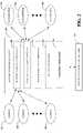
- FIG. 1is a block diagram of sensor monitoring system that evaluates sensor performance based at least in part upon contextual data in accordance with the subject matter described herein.
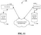
- FIG. 11is a schematic block diagram of a sample-computing environment.
- a componentmay be, but is not limited to being, a process running on a processor, a processor, an object, an executable, a thread of execution, a program, and a computer.
- an application running on a server and the servercan be a component.
- One or more componentsmay reside within a process and/or thread of execution and a component may be localized on one computer and/or distributed between two or more computers.
- the word “exemplary”is used herein to mean serving as an example, instance, or illustration. Any aspect or design described herein as “exemplary” is not necessarily to be construed as preferred or advantageous over other aspects or designs.
- a sensor monitoring system 100that detects degradation in sensor data and/or sensor performance for context-sensitive systems.
- the sensor monitoring systemcan be utilized in combination with a wide variety of arterial flow systems, such as traffic flow systems, to enhance the reliability of such systems.
- Traffic flow systemstypically utilize data collected by a plurality of sensors. Analysis of sensor data can provide critical information to traffic systems. Consequently, the accuracy and reliability of sensor data is critical to such systems.
- the sensor interface component 108can receive data from a predefined set of sensors. Alternatively, an ad hoc set of sensors can be used to collect sensor data provided to the sensor interface component 108 . For example, the sensor interface component 108 can receive sensor data from a set of cell phone users who elect to provide their location information.
- Degradation in performancevaries from intermittent and/or minor inaccuracies to complete failure, where a sensor generates inaccurate data.
- total failurecan be easily identified. For instance, a sensor that fails to register any traffic during Monday morning rush hour may be identified without difficulty.
- intermittent or minor errorscan be difficult to detect, yet can have a cumulative impact upon a traffic flow system dependent upon sensor data.
- the sensor monitoring system 100can include a sensor analyzer component 112 that analyzes the data received from the sensors 102 - 106 and identifies sensors with degraded performance or failure.
- the sensor analyzer component 112 analysiscan be based upon prior data received from a sensor, data recorded by sensors proximate to the sensor being evaluated, and/or contextual information. Context or conditions under which data is collected can be used to determine if a sensor reading is reasonable or unlikely given other sensors and contextual information. For instance, sensor data indicating a large volume of traffic may be well within the expected range of values during rush hour on a particular road segment, but may be suspect if recorded at three o'clock Sunday morning.
- the sensor analyzer component 112can consider various contextual events during sensor analysis, including occurrence of major events (e.g., sporting events, cultural events), weather, accidents, traffic reports in natural language, lane or road closures, historical information, etc.
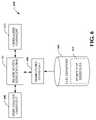
- the sensor analysis component 112can access a traffic system representation 114 that describes probable traffic flow and alters as context changes.
- the traffic system representation 114can be and/or include a weighted graph, where nodes of the graph represent intersections, edges represent road segments between the intersections, and weights associated therewith represent average travel speeds or traffic volume for the road segments/intersections.
- the weightscan alter as context alters. For instance, a first weight can be provided for a road segment at a first time of day and a second weight can be provided to the same road segment at a second time of day.
- Constructed modelscan be applied in real-time to interpret the reliability of sensors, including deterministic and stochastic functions of outputs that can be applied to use the erroneous data (e.g., this sensor can provide valuable information but it has to be resealed, etc.).
- the creation component 118can build probabilistic models to predict sensor failures based on evidence and a library of likely failures.
- One of several discriminative or generative statistical methodscan be employed to predict sensor failure over time. These methods include statistical classifiers such as support vector machines, Bayesian machine learning, learning and usage of dynamic Bayesian networks and related Hidden Markov Models, Continuous Time Bayesian Networks (CTBNs), and families of time series methods such as those employing temporal Bayesian models and models known and ARMA and ARIMA forecasting models.
- statistical classifierssuch as support vector machines, Bayesian machine learning, learning and usage of dynamic Bayesian networks and related Hidden Markov Models, Continuous Time Bayesian Networks (CTBNs), and families of time series methods such as those employing temporal Bayesian models and models known and ARMA and ARIMA forecasting models.
- a generalizer component 610can analyze the traffic system representation 114 and provide speed values to road segments that are not associated with collected data for each category. For instance, for road segments and time segments where no data is available, the generalizer component 610 can assign the speed that is associated with the same road segment at an adjacent time block. If there is no speed associated with an adjacent time block, the generalizer component 610 can assign the segment a speed from a similar road and/or a system-wide average of speeds from similar roads, where similarity can be defined by road class within the traffic system representation 114 .
- a representation of traffic flow and/or road speeds over road segmentscan be used to estimate likely sensor data for sensors associated with the road segments. Actual sensor data collected by such sensor can be evaluated with respect to the estimated or predicted sensor data. Sensor data that varies dramatically from predicted values can be considered suspect.
- the sensor datacan be evaluated and degraded sensor data can be identified.
- Sensor performancecan be evaluated using a comparison of data received from a first sensor to data received from one or more sensors in close proximity to the sensor being evaluated. If the first sensor varies from proximate sensors, it may indicate that the sensor is unreliable.
- Sensor datacan also be analyzed in light of the context information, such as time of day, day of week, etc. For example, a traffic sensor can be expected to generate data indicative of a significantly higher volume of traffic during the weekday rush hours than at three o'clock in the morning on a weekend.
- the determinationis based upon the analysis of sensor data. For example, the determination can be based upon the probability that sensor performance is degraded. The probability of degradation can be compared to a predetermined threshold and if the probability is higher than the threshold, a system operator can be notified. If no notification is to be sent, the process continues at reference numeral 812 . If a notification is to be transmitted, the notification message can be generated at reference numeral 808 .
- the notificationcan identify one or more sensors generating suspect sensor data and include a probability that the suspect sensor data is invalid.
- the notificationis transmitted to one or more users or system operators at reference numeral 810 .
- the processcontinues at reference numeral 914 . If predicted failure is relevant, a notification is generated at reference numeral 910 .
- the notificationcan include predicted failure date or dates and/or a probability of failure.
- the notificationis transmitted to a system operator at reference numeral 912 .
- the system operatorcan utilize such notifications in planning sensor maintenance and/or replacement as well as for budgeting purposes.
- a determinationis made as to whether there are additional sensors to review at reference numeral 914 . If there are additional sensors, the process returns to reference numeral 902 , and previously recorded sensor data is obtained for a selected sensor. If there are no additional sensors, the process terminates.
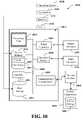
- nonvolatile memory 1022The basic input/output system (BIOS), containing the basic routines to transfer information between elements within the computer 1012 , such as during start-up, is stored in nonvolatile memory 1022 .
- nonvolatile memory 1022can include read only memory (ROM), programmable ROM (PROM), electrically programmable ROM (EPROM), electrically erasable ROM (EEPROM), or flash memory.
- Volatile memory 1020includes random access memory (RAM), which acts as external cache memory.
- a USB portmay be used to provide input to computer 1012 , and to output information from computer 1012 to an output device 1040 .
- Output adapter 1042is provided to illustrate that there are some output devices 1040 like monitors, in-dash displays, speakers, and printers among other output devices 1040 that require special adapters.
- the output adapters 1042include, by way of illustration and not limitation, video and sound cards that provide a means of connection between the output device 1040 and the system bus 1018 . It should be noted that other devices and/or systems of devices provide both input and output capabilities such as remote computer(s) 1044 .
- FIG. 11is a schematic block diagram of a sample-computing environment 1100 with which the claimed subject matter can interact.
- the system 1100includes one or more client(s) 1110 .
- the client(s) 1110can be hardware and/or software (e.g., threads, processes, computing devices).
- the system 1100also includes one or more server(s) 1130 .
- the server(s) 1130can also be hardware and/or software (e.g., threads, processes, computing devices).
- the servers 1130can house threads to perform transformations by employing the claimed subject matter, for example.
- One possible communication between a client 1110 and a server 1130can be in the form of a data packet adapted to be transmitted between two or more computer processes.
- the system 1100includes a communication framework 1150 that can be employed to facilitate communications between the client(s) 1110 and the server(s) 1130 .
- the client(s) 1110are operably connected to one or more client data store(s) 1160 that can be employed to store information local to the client(s) 1110 .
- the server(s) 1130are operably connected to one or more server data store(s) 1140 that can be employed to store information local to the server(s) 1130 .
- the server(s)can a sensor monitoring system that is accessible to a client by way of a network. Users can receive information regarding degradation of sensor or sensor data from the sensor monitoring system within the server by way of the client and the network.
Landscapes
- Business, Economics & Management (AREA)
- Engineering & Computer Science (AREA)
- General Physics & Mathematics (AREA)
- Physics & Mathematics (AREA)
- Human Resources & Organizations (AREA)
- Economics (AREA)
- Strategic Management (AREA)
- Theoretical Computer Science (AREA)
- Chemical & Material Sciences (AREA)
- Tourism & Hospitality (AREA)
- General Business, Economics & Management (AREA)
- Marketing (AREA)
- Entrepreneurship & Innovation (AREA)
- Analytical Chemistry (AREA)
- Operations Research (AREA)
- Quality & Reliability (AREA)
- Game Theory and Decision Science (AREA)
- Development Economics (AREA)
- Health & Medical Sciences (AREA)
- Public Health (AREA)
- Primary Health Care (AREA)
- Educational Administration (AREA)
- General Health & Medical Sciences (AREA)
- Water Supply & Treatment (AREA)
- Traffic Control Systems (AREA)
Abstract
Description
Claims (20)
Priority Applications (5)
| Application Number | Priority Date | Filing Date | Title |
|---|---|---|---|
| US11/770,649US7696866B2 (en) | 2007-06-28 | 2007-06-28 | Learning and reasoning about the context-sensitive reliability of sensors |
| PCT/US2008/066394WO2009005963A1 (en) | 2007-06-28 | 2008-06-10 | Learning and reasoning about the context-sensitive reliability of sensors |
| CN200880022391ACN101689287A (en) | 2007-06-28 | 2008-06-10 | Learning and reasoning about the context-sensitive reliability of sensors |
| JP2010514938AJP4790864B2 (en) | 2007-06-28 | 2008-06-10 | Learning and reasoning about the situation-dependent reliability of sensors |
| EP08770561AEP2176822A4 (en) | 2007-06-28 | 2008-06-10 | Learning and reasoning about the context-sensitive reliability of sensors |
Applications Claiming Priority (1)
| Application Number | Priority Date | Filing Date | Title |
|---|---|---|---|
| US11/770,649US7696866B2 (en) | 2007-06-28 | 2007-06-28 | Learning and reasoning about the context-sensitive reliability of sensors |
Publications (2)
| Publication Number | Publication Date |
|---|---|
| US20090002148A1 US20090002148A1 (en) | 2009-01-01 |
| US7696866B2true US7696866B2 (en) | 2010-04-13 |
Family
ID=40159707
Family Applications (1)
| Application Number | Title | Priority Date | Filing Date |
|---|---|---|---|
| US11/770,649Active2028-05-05US7696866B2 (en) | 2007-06-28 | 2007-06-28 | Learning and reasoning about the context-sensitive reliability of sensors |
Country Status (5)
| Country | Link |
|---|---|
| US (1) | US7696866B2 (en) |
| EP (1) | EP2176822A4 (en) |
| JP (1) | JP4790864B2 (en) |
| CN (1) | CN101689287A (en) |
| WO (1) | WO2009005963A1 (en) |
Cited By (7)
| Publication number | Priority date | Publication date | Assignee | Title |
|---|---|---|---|---|
| US20100100307A1 (en)* | 2008-10-10 | 2010-04-22 | Jin Hong Kim | Universal GPS Traffic Monitoring System |
| US20160077166A1 (en)* | 2014-09-12 | 2016-03-17 | InvenSense, Incorporated | Systems and methods for orientation prediction |
| US10783778B2 (en) | 2017-10-20 | 2020-09-22 | Microsoft Technology Licensing, Llc | Traffic data reconciliation and brokering |
| US11003518B2 (en) | 2016-09-29 | 2021-05-11 | Hewlett-Packard Development Company, L.P. | Component failure prediction |
| US20210325214A1 (en)* | 2018-08-22 | 2021-10-21 | Ntt Docomo, Inc. | Detection device |
| US20230091197A1 (en)* | 2020-02-27 | 2023-03-23 | Siemens Healthcare Diagnostics Inc. | Automatic sensor trace validation using machine learning |
| US11693423B2 (en)* | 2018-12-19 | 2023-07-04 | Waymo Llc | Model for excluding vehicle from sensor field of view |
Families Citing this family (65)
| Publication number | Priority date | Publication date | Assignee | Title |
|---|---|---|---|---|
| JP4978789B2 (en)* | 2007-08-13 | 2012-07-18 | 富士通株式会社 | Sensor evaluation system, sensor evaluation method, and sensor evaluation program |
| CN101753609B (en)* | 2008-12-15 | 2012-09-19 | 中国移动通信集团公司 | Distributed system version control method, node and system |
| US20110157355A1 (en)* | 2009-12-28 | 2011-06-30 | Yuri Ivanov | Method and System for Detecting Events in Environments |
| KR101531449B1 (en)* | 2010-06-30 | 2015-06-24 | 노키아 코포레이션 | Methods and apparatuses for controlling invocation of a sensor |
| US9315333B2 (en)* | 2010-09-09 | 2016-04-19 | Laitram, L.L.C. | System and method for measuring, mapping, and modifying the temperature of a conveyor |
| US9311615B2 (en) | 2010-11-24 | 2016-04-12 | International Business Machines Corporation | Infrastructure asset management |
| US20120173301A1 (en)* | 2011-01-04 | 2012-07-05 | International Business Machines Corporation | System and method for failure association analysis |
| US8457835B2 (en)* | 2011-04-08 | 2013-06-04 | General Electric Company | System and method for use in evaluating an operation of a combustion machine |
| JP5358814B2 (en)* | 2011-05-31 | 2013-12-04 | トヨタ自動車株式会社 | Sensor information supplement system and sensor information supplement method |
| WO2013024672A1 (en)* | 2011-08-12 | 2013-02-21 | オムロン株式会社 | Information management device, information management program, and information management method |
| CN103975557B (en)* | 2011-10-28 | 2018-09-07 | 瑞典爱立信有限公司 | The method and system of evaluation for sensor observation |
| WO2013116993A1 (en)* | 2012-02-08 | 2013-08-15 | Telefonaktiebolaget L M Ericsson | Method, computer program, computer program product and system for handling sensor data |
| DE102012209443B4 (en)* | 2012-06-05 | 2022-10-20 | Robert Bosch Gmbh | Method for carrying out a diagnosis of a functional unit connected to a control unit in a motor vehicle and device set up for carrying out the method |
| US20140159914A1 (en)* | 2012-07-24 | 2014-06-12 | Alan C. Heller | Electronic reporting systems and methods |
| DE102012218362A1 (en)* | 2012-10-09 | 2014-04-24 | Bayerische Motoren Werke Aktiengesellschaft | Estimation of the road type using sensor-based environmental data |
| CN102970366A (en)* | 2012-11-23 | 2013-03-13 | 江苏物联网研究发展中心 | Weather monitoring system based on geographic information system |
| KR101606239B1 (en) | 2013-05-31 | 2016-03-24 | 삼성에스디에스 주식회사 | System and method for analyzing sensing data |
| US10552511B2 (en)* | 2013-06-24 | 2020-02-04 | Infosys Limited | Systems and methods for data-driven anomaly detection |
| CN103916927B (en)* | 2014-03-17 | 2017-06-13 | 华中科技大学 | A kind of wireless sensor network routing method based on improvement harmonic search algorithm |
| US10203231B2 (en)* | 2014-07-23 | 2019-02-12 | Hach Company | Sonde |
| WO2016043635A1 (en)* | 2014-09-16 | 2016-03-24 | Telefonaktiebolaget L M Ericsson (Publ) | Sensor system of master and slave sensors, and method therein |
| EP3016352B1 (en)* | 2014-11-03 | 2019-02-06 | Fujitsu Limited | Method of managing sensor network |
| JP2016162249A (en)* | 2015-03-03 | 2016-09-05 | 住友電気工業株式会社 | Sensor management device, sensor, monitoring system, sensor management method, sensor management program, monitoring method, and monitoring program |
| US10048996B1 (en)* | 2015-09-29 | 2018-08-14 | Amazon Technologies, Inc. | Predicting infrastructure failures in a data center for hosted service mitigation actions |
| US11151654B2 (en) | 2015-09-30 | 2021-10-19 | Johnson Controls Tyco IP Holdings LLP | System and method for determining risk profile, adjusting insurance premiums and automatically collecting premiums based on sensor data |
| US10902524B2 (en) | 2015-09-30 | 2021-01-26 | Sensormatic Electronics, LLC | Sensor based system and method for augmenting underwriting of insurance policies |
| US11436911B2 (en)* | 2015-09-30 | 2022-09-06 | Johnson Controls Tyco IP Holdings LLP | Sensor based system and method for premises safety and operational profiling based on drift analysis |
| US10690511B2 (en)* | 2015-12-26 | 2020-06-23 | Intel Corporation | Technologies for managing sensor anomalies |
| US10510006B2 (en)* | 2016-03-09 | 2019-12-17 | Uptake Technologies, Inc. | Handling of predictive models based on asset location |
| US10552914B2 (en) | 2016-05-05 | 2020-02-04 | Sensormatic Electronics, LLC | Method and apparatus for evaluating risk based on sensor monitoring |
| US10810676B2 (en) | 2016-06-06 | 2020-10-20 | Sensormatic Electronics, LLC | Method and apparatus for increasing the density of data surrounding an event |
| US10489752B2 (en)* | 2016-08-26 | 2019-11-26 | General Electric Company | Failure mode ranking in an asset management system |
| CN106507315B (en)* | 2016-11-24 | 2019-06-28 | 西安交通大学 | Urban traffic accident prediction technique and system based on network social intercourse media data |
| US10337753B2 (en)* | 2016-12-23 | 2019-07-02 | Abb Ag | Adaptive modeling method and system for MPC-based building energy control |
| WO2018125245A1 (en)* | 2016-12-31 | 2018-07-05 | Intel Corporation | Crowdsourced failure mode prediction |
| US11537868B2 (en)* | 2017-11-13 | 2022-12-27 | Lyft, Inc. | Generation and update of HD maps using data from heterogeneous sources |
| JP7006199B2 (en)* | 2017-12-01 | 2022-01-24 | オムロン株式会社 | Data generator, data generator, data generator and sensor device |
| EP3725135A1 (en)* | 2017-12-12 | 2020-10-21 | Schreder Sa | Luminaire network with sensors |
| AU2019233731B2 (en) | 2018-03-16 | 2024-09-12 | Schreder S.A. | Luminaire network with sensors |
| WO2020036818A1 (en)* | 2018-08-12 | 2020-02-20 | Presenso, Ltd. | System and method for forecasting industrial machine failures |
| WO2020117673A1 (en)* | 2018-12-03 | 2020-06-11 | DSi Digital, LLC | Data interaction platforms utilizing dynamic relational awareness |
| CN109857018B (en)* | 2019-01-28 | 2020-09-25 | 中国地质大学(武汉) | Digital sensor soft model system |
| US11205343B2 (en)* | 2019-02-20 | 2021-12-21 | GM Global Technology Operations LLC | Methods and systems for interpretating traffic signals and negotiating signalized intersections |
| GB201904334D0 (en) | 2019-03-28 | 2019-05-15 | Sisaf Ltd | Carrier system for preparing herbaceous extracts |
| US11069161B2 (en) | 2019-09-30 | 2021-07-20 | Ford Global Technologies, Llc | Adaptive sensor fusion |
| JP7222344B2 (en)* | 2019-12-06 | 2023-02-15 | 横河電機株式会社 | Determination device, determination method, determination program, learning device, learning method, and learning program |
| GB201919198D0 (en)* | 2019-12-23 | 2020-02-05 | Univ Surrey | Sensor fault prediction method and apparatus |
| US11614560B2 (en)* | 2019-12-27 | 2023-03-28 | International Business Machines Corporation | Integration of physical sensors in a data assimilation framework |
| JP7333284B2 (en)* | 2020-03-16 | 2023-08-24 | 株式会社日立製作所 | Maintenance support system and maintenance support method |
| CN111524348A (en)* | 2020-04-14 | 2020-08-11 | 长安大学 | A long-term and short-term traffic flow prediction model and method |
| JP7512230B2 (en)* | 2020-06-24 | 2024-07-08 | 株式会社東芝 | Equipment failure prediction system, equipment failure prediction method, and equipment failure prediction program |
| US20220044151A1 (en)* | 2020-08-06 | 2022-02-10 | Front End Analytics Llc | Apparatus and method for electronic determination of system data integrity |
| WO2022033677A1 (en)* | 2020-08-12 | 2022-02-17 | Siemens Aktiengesellschaft | System and method for adaptive traffic signal planning and control |
| KR102425529B1 (en)* | 2020-12-08 | 2022-07-25 | 한남대학교 산학협력단 | Self-driving forklift using camera sensor |
| EP4075130A1 (en)* | 2021-04-15 | 2022-10-19 | Infineon Technologies AG | Sensing device for sensing an environmental parameter and method for determining an information about a functional state of a sensing device using a neural network |
| CN115237510A (en)* | 2021-04-23 | 2022-10-25 | 沃尔沃汽车公司 | Recommendation providing apparatus, system and method for use in vehicles |
| DE102021209681A1 (en) | 2021-09-03 | 2023-03-09 | Robert Bosch Gesellschaft mit beschränkter Haftung | Concept for supporting a motor vehicle with an infrastructure |
| US12056722B1 (en) | 2021-10-04 | 2024-08-06 | Quanata, Llc | Systems and methods for managing vehicle operator profiles based on relative telematics inferences via a telematics marketplace |
| US12026729B1 (en) | 2021-10-04 | 2024-07-02 | BlueOwl, LLC | Systems and methods for match evaluation based on change in telematics inferences via a telematics marketplace |
| US12373853B2 (en) | 2021-10-04 | 2025-07-29 | Quanata, Llc | Systems and methods for managing vehicle operator profiles based on telematics inferences via an auction telematics marketplace with a bid profit predictive model |
| CN114186872A (en)* | 2021-12-14 | 2022-03-15 | 深圳中广核工程设计有限公司 | Emergency state assessment methods, devices and computer equipment for nuclear power plants |
| WO2023195049A1 (en)* | 2022-04-04 | 2023-10-12 | 日本電気株式会社 | Monitoring device, monitoring system, monitoring method, and non-transitory computer-readable medium |
| KR102850667B1 (en)* | 2022-12-12 | 2025-08-27 | 주식회사 카카오모빌리티 | Method and system for controlling autonomous driving by search and train of autonomous driving software linked with route guidance |
| CN115962797B (en)* | 2022-12-28 | 2024-05-24 | 国网江苏省电力有限公司泰州供电分公司 | Sensor reliability test method and system based on temperature stress |
| GB2632291A (en)* | 2023-07-31 | 2025-02-05 | Tyco Fire & Security Gmbh | Applying machine learning to detector data |
Citations (24)
| Publication number | Priority date | Publication date | Assignee | Title |
|---|---|---|---|---|
| US5400246A (en)* | 1989-05-09 | 1995-03-21 | Ansan Industries, Ltd. | Peripheral data acquisition, monitor, and adaptive control system via personal computer |
| US5493692A (en) | 1993-12-03 | 1996-02-20 | Xerox Corporation | Selective delivery of electronic messages in a multiple computer system based on context and environment of a user |
| US5544321A (en) | 1993-12-03 | 1996-08-06 | Xerox Corporation | System for granting ownership of device by user based on requested level of ownership, present state of the device, and the context of the device |
| WO1998000787A1 (en) | 1996-06-28 | 1998-01-08 | Datalink Systems Corporation | Electronic mail system for receiving and forwarding e-mail messages based on subscriber supplied criteria |
| US5812865A (en) | 1993-12-03 | 1998-09-22 | Xerox Corporation | Specifying and establishing communication data paths between particular media devices in multiple media device computing systems based on context of a user or users |
| US5835886A (en) | 1994-10-26 | 1998-11-10 | Siemens Aktiengesellschaft | Method for analyzing a measurement value and measurement value analyzer for carrying out the method |
| US20010040591A1 (en) | 1998-12-18 | 2001-11-15 | Abbott Kenneth H. | Thematic response to a computer user's context, such as by a wearable personal computer |
| US20010040590A1 (en) | 1998-12-18 | 2001-11-15 | Abbott Kenneth H. | Thematic response to a computer user's context, such as by a wearable personal computer |
| US20010043232A1 (en) | 1998-12-18 | 2001-11-22 | Abbott Kenneth H. | Thematic response to a computer user's context, such as by a wearable personal computer |
| US20020032689A1 (en) | 1999-12-15 | 2002-03-14 | Abbott Kenneth H. | Storing and recalling information to augment human memories |
| US20020044152A1 (en) | 2000-10-16 | 2002-04-18 | Abbott Kenneth H. | Dynamic integration of computer generated and real world images |
| US20020052963A1 (en) | 1998-12-18 | 2002-05-02 | Abbott Kenneth H. | Managing interactions between computer users' context models |
| US20020054174A1 (en) | 1998-12-18 | 2002-05-09 | Abbott Kenneth H. | Thematic response to a computer user's context, such as by a wearable personal computer |
| US20020054130A1 (en) | 2000-10-16 | 2002-05-09 | Abbott Kenneth H. | Dynamically displaying current status of tasks |
| US20020078204A1 (en) | 1998-12-18 | 2002-06-20 | Dan Newell | Method and system for controlling presentation of information to a user based on the user's condition |
| US20020080156A1 (en) | 1998-12-18 | 2002-06-27 | Abbott Kenneth H. | Supplying notifications related to supply and consumption of user context data |
| US20020083025A1 (en) | 1998-12-18 | 2002-06-27 | Robarts James O. | Contextual responses based on automated learning techniques |
| US20020087525A1 (en) | 2000-04-02 | 2002-07-04 | Abbott Kenneth H. | Soliciting information based on a computer user's context |
| US20030046401A1 (en) | 2000-10-16 | 2003-03-06 | Abbott Kenneth H. | Dynamically determing appropriate computer user interfaces |
| KR20030045420A (en) | 2001-12-04 | 2003-06-11 | (주) 이스텍 | The measuring system for water quality |
| US6747675B1 (en) | 1998-12-18 | 2004-06-08 | Tangis Corporation | Mediating conflicts in computer user's context data |
| US6812937B1 (en) | 1998-12-18 | 2004-11-02 | Tangis Corporation | Supplying enhanced computer user's context data |
| US6847892B2 (en) | 2001-10-29 | 2005-01-25 | Digital Angel Corporation | System for localizing and sensing objects and providing alerts |
| JP2005250557A (en) | 2004-03-01 | 2005-09-15 | Mail Support Systems:Kk | Daily water quality monitoring system using mobile technology |
Family Cites Families (7)
| Publication number | Priority date | Publication date | Assignee | Title |
|---|---|---|---|---|
| DE69813040T2 (en)* | 1998-08-17 | 2003-10-16 | Aspen Technology, Inc. | METHOD AND DEVICE FOR SENSOR CONFIRMATION |
| US6598195B1 (en)* | 2000-08-21 | 2003-07-22 | General Electric Company | Sensor fault detection, isolation and accommodation |
| US7373283B2 (en)* | 2001-02-22 | 2008-05-13 | Smartsignal Corporation | Monitoring and fault detection system and method using improved empirical model for range extrema |
| SE522545C2 (en)* | 2001-03-06 | 2004-02-17 | Goalart Ab | System, device and method for diagnosing flow processes |
| DE60231203D1 (en)* | 2001-04-26 | 2009-04-02 | Abb As | METHOD FOR MONITORING AND DETECTING A SENSOR FAILURE IN OIL AND GAS PRODUCTION SYSTEMS |
| JP4041395B2 (en)* | 2002-12-27 | 2008-01-30 | 東京瓦斯株式会社 | Failure detection apparatus and failure detection method |
| JP4175312B2 (en)* | 2004-09-17 | 2008-11-05 | 株式会社日立製作所 | Traffic information prediction device |
- 2007
- 2007-06-28USUS11/770,649patent/US7696866B2/enactiveActive
- 2008
- 2008-06-10JPJP2010514938Apatent/JP4790864B2/enactiveActive
- 2008-06-10EPEP08770561Apatent/EP2176822A4/ennot_activeWithdrawn
- 2008-06-10WOPCT/US2008/066394patent/WO2009005963A1/enactiveApplication Filing
- 2008-06-10CNCN200880022391Apatent/CN101689287A/enactivePending
Patent Citations (40)
| Publication number | Priority date | Publication date | Assignee | Title |
|---|---|---|---|---|
| US5400246A (en)* | 1989-05-09 | 1995-03-21 | Ansan Industries, Ltd. | Peripheral data acquisition, monitor, and adaptive control system via personal computer |
| US5493692A (en) | 1993-12-03 | 1996-02-20 | Xerox Corporation | Selective delivery of electronic messages in a multiple computer system based on context and environment of a user |
| US5544321A (en) | 1993-12-03 | 1996-08-06 | Xerox Corporation | System for granting ownership of device by user based on requested level of ownership, present state of the device, and the context of the device |
| US5555376A (en) | 1993-12-03 | 1996-09-10 | Xerox Corporation | Method for granting a user request having locational and contextual attributes consistent with user policies for devices having locational attributes consistent with the user request |
| US5603054A (en) | 1993-12-03 | 1997-02-11 | Xerox Corporation | Method for triggering selected machine event when the triggering properties of the system are met and the triggering conditions of an identified user are perceived |
| US5611050A (en) | 1993-12-03 | 1997-03-11 | Xerox Corporation | Method for selectively performing event on computer controlled device whose location and allowable operation is consistent with the contextual and locational attributes of the event |
| US5812865A (en) | 1993-12-03 | 1998-09-22 | Xerox Corporation | Specifying and establishing communication data paths between particular media devices in multiple media device computing systems based on context of a user or users |
| US5835886A (en) | 1994-10-26 | 1998-11-10 | Siemens Aktiengesellschaft | Method for analyzing a measurement value and measurement value analyzer for carrying out the method |
| WO1998000787A1 (en) | 1996-06-28 | 1998-01-08 | Datalink Systems Corporation | Electronic mail system for receiving and forwarding e-mail messages based on subscriber supplied criteria |
| US20020080156A1 (en) | 1998-12-18 | 2002-06-27 | Abbott Kenneth H. | Supplying notifications related to supply and consumption of user context data |
| US6812937B1 (en) | 1998-12-18 | 2004-11-02 | Tangis Corporation | Supplying enhanced computer user's context data |
| US20010043232A1 (en) | 1998-12-18 | 2001-11-22 | Abbott Kenneth H. | Thematic response to a computer user's context, such as by a wearable personal computer |
| US20010043231A1 (en) | 1998-12-18 | 2001-11-22 | Abbott Kenneth H. | Thematic response to a computer user's context, such as by a wearable personal computer |
| US20050034078A1 (en) | 1998-12-18 | 2005-02-10 | Abbott Kenneth H. | Mediating conflicts in computer user's context data |
| US6842877B2 (en) | 1998-12-18 | 2005-01-11 | Tangis Corporation | Contextual responses based on automated learning techniques |
| US20020052963A1 (en) | 1998-12-18 | 2002-05-02 | Abbott Kenneth H. | Managing interactions between computer users' context models |
| US20020052930A1 (en) | 1998-12-18 | 2002-05-02 | Abbott Kenneth H. | Managing interactions between computer users' context models |
| US20020054174A1 (en) | 1998-12-18 | 2002-05-09 | Abbott Kenneth H. | Thematic response to a computer user's context, such as by a wearable personal computer |
| US20010040590A1 (en) | 1998-12-18 | 2001-11-15 | Abbott Kenneth H. | Thematic response to a computer user's context, such as by a wearable personal computer |
| US20020078204A1 (en) | 1998-12-18 | 2002-06-20 | Dan Newell | Method and system for controlling presentation of information to a user based on the user's condition |
| US20010040591A1 (en) | 1998-12-18 | 2001-11-15 | Abbott Kenneth H. | Thematic response to a computer user's context, such as by a wearable personal computer |
| US20020083158A1 (en) | 1998-12-18 | 2002-06-27 | Abbott Kenneth H. | Managing interactions between computer users' context models |
| US20020083025A1 (en) | 1998-12-18 | 2002-06-27 | Robarts James O. | Contextual responses based on automated learning techniques |
| US20020080155A1 (en) | 1998-12-18 | 2002-06-27 | Abbott Kenneth H. | Supplying notifications related to supply and consumption of user context data |
| US6801223B1 (en) | 1998-12-18 | 2004-10-05 | Tangis Corporation | Managing interactions between computer users' context models |
| US20020099817A1 (en) | 1998-12-18 | 2002-07-25 | Abbott Kenneth H. | Managing interactions between computer users' context models |
| US6466232B1 (en) | 1998-12-18 | 2002-10-15 | Tangis Corporation | Method and system for controlling presentation of information to a user based on the user's condition |
| US6791580B1 (en) | 1998-12-18 | 2004-09-14 | Tangis Corporation | Supplying notifications related to supply and consumption of user context data |
| US6747675B1 (en) | 1998-12-18 | 2004-06-08 | Tangis Corporation | Mediating conflicts in computer user's context data |
| US20030154476A1 (en) | 1999-12-15 | 2003-08-14 | Abbott Kenneth H. | Storing and recalling information to augment human memories |
| US6549915B2 (en) | 1999-12-15 | 2003-04-15 | Tangis Corporation | Storing and recalling information to augment human memories |
| US6513046B1 (en) | 1999-12-15 | 2003-01-28 | Tangis Corporation | Storing and recalling information to augment human memories |
| US20020032689A1 (en) | 1999-12-15 | 2002-03-14 | Abbott Kenneth H. | Storing and recalling information to augment human memories |
| US20020087525A1 (en) | 2000-04-02 | 2002-07-04 | Abbott Kenneth H. | Soliciting information based on a computer user's context |
| US20030046401A1 (en) | 2000-10-16 | 2003-03-06 | Abbott Kenneth H. | Dynamically determing appropriate computer user interfaces |
| US20020054130A1 (en) | 2000-10-16 | 2002-05-09 | Abbott Kenneth H. | Dynamically displaying current status of tasks |
| US20020044152A1 (en) | 2000-10-16 | 2002-04-18 | Abbott Kenneth H. | Dynamic integration of computer generated and real world images |
| US6847892B2 (en) | 2001-10-29 | 2005-01-25 | Digital Angel Corporation | System for localizing and sensing objects and providing alerts |
| KR20030045420A (en) | 2001-12-04 | 2003-06-11 | (주) 이스텍 | The measuring system for water quality |
| JP2005250557A (en) | 2004-03-01 | 2005-09-15 | Mail Support Systems:Kk | Daily water quality monitoring system using mobile technology |
Non-Patent Citations (34)
| Title |
|---|
| Andy Harter, et al., A Distributed Location System for the Active Office, IEEE Network, 1994, pp. 62-70. |
| Bill N. Schilit, et al., Customizing Mobile Applications, Proceedings USENIX Symposium on Mobile and Location Independent Computing, Aug. 1993, 9 pages. |
| Bill N. Schilit, et al., Disseminationg Active Map Information to Mobile Hosts, IEEE Network, 1994, pp. 22-32, vol. 8-No. 5. |
| Bill N. Schilit, et al., Disseminationg Active Map Information to Mobile Hosts, IEEE Network, 1994, pp. 22-32, vol. 8—No. 5. |
| Bill N. Schilit, et al., The ParcTab Mobile Computing System, IEEE WWOS-IV, 1993, 4 pages. |
| Bill Schilit, et al., Context-Aware Computing Applications, In Proceedings of the Workshop on Mobile Computing Systems and Applications, Dec. 1994. pp. 85-90. |
| Bradley J. Rhodes, Remembrance Agent: A continuously running automated information retrieval system, The Proceedings of The First International Conference on The Practical Application Of Intelligent Agents and Multi Agent Technology, 1996, pp. 487-495. |
| Bradley J. Rhodes, The Wearable Remembrance Agent: A System for Augmented Memory, Personal Technologies Journal Special Issue on Wearable Computing, 1997, 12 pages. |
| Bradley J. Rhodes, The Wearable Remembrance Agent: A System for Augmented Theory, The Proceedings of The First International Symposium on Wearable Computers, Oct. 1997, pp. 123-128. |
| Eric Horvitz, et al., Attention-Sensitive Alerting in Computing Systems, Microsoft Research, Aug. 1999. |
| Eric Horvitz, et al., In Pursuit of Effective Handsfree Decision Support: Coupling Bayesian Inference, Speech Understanding, and User Models, 1995, 8 pages. |
| Guanling Chen, et al., A Survey of Context-Aware Mobile Computing Research, Dartmouth Computer Science Technical Report, 2000, 16 pages. |
| International Search Report dated Dec. 12, 2008 for PCT Application Serial No. US2008/066394 , 3 Pages. |
| International Search Report dated Sep. 29, 2003 for PCT Application Serial No. 00/20685, 3 Pages. |
| M. Billinghurst, et al., An Evaluation of Wearable Information Spaces, Proceedings of the Virtual Reality Annual International Symposium, 1998, 8 pages. |
| Mark Billinghurst, et al., Wearable Devices: New Ways to Manage Information, IEEE Computer Society, Jan. 1999, pp. 57-64. |
| Mark Billinghurst, Research Directions in Wearable Computing, University of Washington, May 1998, 48 pages. |
| Mark Weiser, Some Computer Science Issues in Ubiquitous Computing, Communications of the ACM, Jul. 1993, pp. 75-84, vol. 36-No. 7. |
| Mark Weiser, Some Computer Science Issues in Ubiquitous Computing, Communications of the ACM, Jul. 1993, pp. 75-84, vol. 36—No. 7. |
| Mark Weiser, The Computer for the 21st Century, Scientific American, Sep. 1991, 8 pages. |
| Marvin Theimer, et al., Operating System Issues for PDAs, in Fourth Workshop on Workstation Operating Systems, 1993, 7 pages. |
| Mike Spreitzer et al., Scalable, Secure, Mobile Computing with Location Information, Communications of the ACM, Jul. 1993, 1 page, vol. 36-No. 7. |
| Mike Spreitzer et al., Scalable, Secure, Mobile Computing with Location Information, Communications of the ACM, Jul. 1993, 1 page, vol. 36—No. 7. |
| Mike Spreitzer, et al., Architectural Considerations for Scalable, Secure, Mobile Computing with Location Information, In The 14th International Conference on Distributed Computing Systems, Jun. 1994, pp. 29-38. |
| Mike Spreitzer, et al., Providing Location Information in a Ubiquitous Computing Environment, SIGOPS '93, 1993, pp. 270-283. |
| Robert M. Losee, Jr., Minimizing information overload: the ranking of electronic messages, Journal of Information Science 15, Elsevier Science Publishers B.V., 1989, pp. 179-189. |
| Roy Want, Active Badges and Personal Interactive Computing Objects, IEEE Transactions on Consumer Electronics, 1992, 11 pages, vol. 38-No. 1. |
| Roy Want, Active Badges and Personal Interactive Computing Objects, IEEE Transactions on Consumer Electronics, 1992, 11 pages, vol. 38—No. 1. |
| Roy Want, et al., The Active Badge Location System, ACM Transactions on Information Systems, Jan. 1992, pp. 91-102, vol. 10-No. 1. |
| Roy Want, et al., The Active Badge Location System, ACM Transactions on Information Systems, Jan. 1992, pp. 91-102, vol. 10—No. 1. |
| T. Joachims, Text categorization with support vector machines: learning with many relevant features, Machine Learning, European Conference on Machine Learning, Apr. 21, 1998, pp. 137-142. |
| Thad Eugene Starner, Wearable Computing and Contextual Awareness, Massachusetts Institute of Technology, Jun. 1999, 248 pages. |
| William Noah Schilt, A System Architecture for Context-Aware Mobile Computing, Columbia University, 1995, 153 pages. |
| Workshop on Wearable Computing Systems, Aug. 19-21, 1996. |
Cited By (11)
| Publication number | Priority date | Publication date | Assignee | Title |
|---|---|---|---|---|
| US20100100307A1 (en)* | 2008-10-10 | 2010-04-22 | Jin Hong Kim | Universal GPS Traffic Monitoring System |
| US8386157B2 (en)* | 2008-10-10 | 2013-02-26 | Jin Hong Kim | Universal GPS traffic monitoring system |
| US20160077166A1 (en)* | 2014-09-12 | 2016-03-17 | InvenSense, Incorporated | Systems and methods for orientation prediction |
| US11003518B2 (en) | 2016-09-29 | 2021-05-11 | Hewlett-Packard Development Company, L.P. | Component failure prediction |
| US10783778B2 (en) | 2017-10-20 | 2020-09-22 | Microsoft Technology Licensing, Llc | Traffic data reconciliation and brokering |
| US20210325214A1 (en)* | 2018-08-22 | 2021-10-21 | Ntt Docomo, Inc. | Detection device |
| US11680832B2 (en)* | 2018-08-22 | 2023-06-20 | Ntt Docomo, Inc. | Detection device |
| US11693423B2 (en)* | 2018-12-19 | 2023-07-04 | Waymo Llc | Model for excluding vehicle from sensor field of view |
| US12140962B2 (en) | 2018-12-19 | 2024-11-12 | Waymo Llc | Model for excluding vehicle from sensor field of view |
| US20230091197A1 (en)* | 2020-02-27 | 2023-03-23 | Siemens Healthcare Diagnostics Inc. | Automatic sensor trace validation using machine learning |
| US12124325B2 (en)* | 2020-02-27 | 2024-10-22 | Siemens Healthcare Diagnostics Inc. | Automatic sensor trace validation using machine learning |
Also Published As
| Publication number | Publication date |
|---|---|
| CN101689287A (en) | 2010-03-31 |
| US20090002148A1 (en) | 2009-01-01 |
| JP4790864B2 (en) | 2011-10-12 |
| EP2176822A1 (en) | 2010-04-21 |
| JP2010533903A (en) | 2010-10-28 |
| EP2176822A4 (en) | 2012-06-20 |
| WO2009005963A1 (en) | 2009-01-08 |
Similar Documents
| Publication | Publication Date | Title |
|---|---|---|
| US7696866B2 (en) | Learning and reasoning about the context-sensitive reliability of sensors | |
| US7948400B2 (en) | Predictive models of road reliability for traffic sensor configuration and routing | |
| Pi et al. | Visual cause analytics for traffic congestion | |
| Van Lint | Reliable travel time prediction for freeways | |
| CN1776739B (en) | Traffic prediction using model-setting and analyzing to probability relativity and environment data | |
| US8090530B2 (en) | Computation of travel routes, durations, and plans over multiple contexts | |
| EP1657693A2 (en) | Traffic forecasting employing modeling and analysis of probabilistic interdependencies and contextual data | |
| Zheng et al. | Framework for fusing traffic information from social and physical transportation data | |
| Shoman et al. | Deep learning framework for predicting bus delays on multiple routes using heterogenous datasets | |
| JP2021182189A (en) | Accident prediction method, computer program, accident prediction device, and learning model generation method | |
| Behboudi et al. | Recent advances in traffic accident analysis and prediction: A comprehensive review of machine learning techniques | |
| Zhang et al. | Mining transportation information from social media for planned and unplanned events | |
| Iqbal et al. | An efficient traffic incident detection and classification framework by leveraging the efficacy of model stacking | |
| Kim et al. | Reinforcement learning approach to develop variable speed limit strategy using vehicle data and simulations | |
| Hassannayebi et al. | A data analytics framework for reliable bus arrival time prediction using artificial neural networks | |
| Jiang et al. | Real-time urban traffic monitoring using transit buses as probes | |
| Islam et al. | Calibrated confidence learning for large-scale real-time crash and severity prediction | |
| Gu et al. | Cycle Maximum Queue Length Estimation: An Integrated Deep Learning and Adaptive Neuro-Fuzzy Inference System Framework (October 2024) | |
| Finogeev et al. | Proactive big data analysis for traffic accident prediction | |
| US20150348407A1 (en) | Recommendation Engine Based on a Representation of the Local Environment Augmented by Citizen Sensor Reports | |
| Lin | Data science application in intelligent transportation systems: An integrative approach for border delay prediction and traffic accident analysis | |
| Mamdoohi et al. | Machine learning and reverse methods for a deeper understanding of public roadway improvement action impacts during execution | |
| Moonam | Developing sampling strategies and predicting freeway travel time using Bluetooth data | |
| Martínez-Díaz | Travel Time Information Revisited | |
| Juri et al. | An Exploration of the Use of Artificial Intelligence for Enhanced Traffic Management, Operations and Safety |
Legal Events
| Date | Code | Title | Description |
|---|---|---|---|
| AS | Assignment | Owner name:MICROSOFT CORPORATION, WASHINGTON Free format text:ASSIGNMENT OF ASSIGNORS INTEREST;ASSIGNOR:HORVITZ, ERIC J.;REEL/FRAME:019503/0695 Effective date:20070628 Owner name:MICROSOFT CORPORATION,WASHINGTON Free format text:ASSIGNMENT OF ASSIGNORS INTEREST;ASSIGNOR:HORVITZ, ERIC J.;REEL/FRAME:019503/0695 Effective date:20070628 | |
| FEPP | Fee payment procedure | Free format text:PAYOR NUMBER ASSIGNED (ORIGINAL EVENT CODE: ASPN); ENTITY STATUS OF PATENT OWNER: LARGE ENTITY | |
| STCF | Information on status: patent grant | Free format text:PATENTED CASE | |
| FPAY | Fee payment | Year of fee payment:4 | |
| AS | Assignment | Owner name:MICROSOFT TECHNOLOGY LICENSING, LLC, WASHINGTON Free format text:ASSIGNMENT OF ASSIGNORS INTEREST;ASSIGNOR:MICROSOFT CORPORATION;REEL/FRAME:034542/0001 Effective date:20141014 | |
| MAFP | Maintenance fee payment | Free format text:PAYMENT OF MAINTENANCE FEE, 8TH YEAR, LARGE ENTITY (ORIGINAL EVENT CODE: M1552) Year of fee payment:8 | |
| MAFP | Maintenance fee payment | Free format text:PAYMENT OF MAINTENANCE FEE, 12TH YEAR, LARGE ENTITY (ORIGINAL EVENT CODE: M1553); ENTITY STATUS OF PATENT OWNER: LARGE ENTITY Year of fee payment:12 |