US7696847B2 - High-field synchrocyclotron - Google Patents
High-field synchrocyclotronDownload PDFInfo
- Publication number
- US7696847B2 US7696847B2US12/425,625US42562509AUS7696847B2US 7696847 B2US7696847 B2US 7696847B2US 42562509 AUS42562509 AUS 42562509AUS 7696847 B2US7696847 B2US 7696847B2
- Authority
- US
- United States
- Prior art keywords
- magnetic
- pole
- coils
- acceleration
- magnet structure
- Prior art date
- Legal status (The legal status is an assumption and is not a legal conclusion. Google has not performed a legal analysis and makes no representation as to the accuracy of the status listed.)
- Expired - Fee Related
Links
- 230000005291magnetic effectEffects0.000claimsabstractdescription182
- 230000001133accelerationEffects0.000claimsabstractdescription152
- 230000001965increasing effectEffects0.000claimsabstractdescription33
- 230000007423decreaseEffects0.000claimsabstractdescription14
- 238000007493shaping processMethods0.000claimsabstractdescription9
- 229910000657niobium-tinInorganic materials0.000claimsdescription20
- 238000000034methodMethods0.000claimsdescription18
- 239000000463materialSubstances0.000claimsdescription14
- 230000005684electric fieldEffects0.000claimsdescription7
- 230000003247decreasing effectEffects0.000claimsdescription6
- 238000000926separation methodMethods0.000claimsdescription2
- 239000002245particleSubstances0.000abstractdescription25
- 150000002500ionsChemical class0.000description63
- XEEYBQQBJWHFJM-UHFFFAOYSA-NIronChemical compound[Fe]XEEYBQQBJWHFJM-UHFFFAOYSA-N0.000description47
- 239000004020conductorSubstances0.000description25
- 229910052742ironInorganic materials0.000description23
- 239000002887superconductorSubstances0.000description18
- 239000010949copperSubstances0.000description15
- 230000005294ferromagnetic effectEffects0.000description14
- 238000010791quenchingMethods0.000description14
- 239000000243solutionSubstances0.000description12
- RYGMFSIKBFXOCR-UHFFFAOYSA-NCopperChemical compound[Cu]RYGMFSIKBFXOCR-UHFFFAOYSA-N0.000description11
- 239000002131composite materialSubstances0.000description11
- 229910052802copperInorganic materials0.000description11
- 238000000605extractionMethods0.000description11
- 238000004804windingMethods0.000description11
- 238000013461designMethods0.000description8
- 229910001275Niobium-titaniumInorganic materials0.000description7
- 230000006870functionEffects0.000description7
- RJSRQTFBFAJJIL-UHFFFAOYSA-Nniobium titaniumChemical compound[Ti].[Nb]RJSRQTFBFAJJIL-UHFFFAOYSA-N0.000description7
- 230000010355oscillationEffects0.000description6
- 239000011159matrix materialSubstances0.000description5
- 239000010935stainless steelSubstances0.000description5
- 229910001220stainless steelInorganic materials0.000description5
- 239000004593EpoxySubstances0.000description4
- 229910001209Low-carbon steelInorganic materials0.000description4
- 230000004907fluxEffects0.000description4
- 239000007788liquidSubstances0.000description4
- 239000010955niobiumSubstances0.000description4
- GUCVJGMIXFAOAE-UHFFFAOYSA-Nniobium atomChemical compound[Nb]GUCVJGMIXFAOAE-UHFFFAOYSA-N0.000description4
- 230000000171quenching effectEffects0.000description4
- 239000013598vectorSubstances0.000description4
- ATJFFYVFTNAWJD-UHFFFAOYSA-NTinChemical compound[Sn]ATJFFYVFTNAWJD-UHFFFAOYSA-N0.000description3
- 238000013459approachMethods0.000description3
- 230000008878couplingEffects0.000description3
- 238000010168coupling processMethods0.000description3
- 238000005859coupling reactionMethods0.000description3
- 239000003302ferromagnetic materialSubstances0.000description3
- 229910052751metalInorganic materials0.000description3
- 239000002184metalSubstances0.000description3
- 239000000203mixtureSubstances0.000description3
- 229910052758niobiumInorganic materials0.000description3
- 230000035515penetrationEffects0.000description3
- 229920006395saturated elastomerPolymers0.000description3
- OKTJSMMVPCPJKN-UHFFFAOYSA-NCarbonChemical compound[C]OKTJSMMVPCPJKN-UHFFFAOYSA-N0.000description2
- UFHFLCQGNIYNRP-UHFFFAOYSA-NHydrogenChemical compound[H][H]UFHFLCQGNIYNRP-UHFFFAOYSA-N0.000description2
- PXHVJJICTQNCMI-UHFFFAOYSA-NNickelChemical compound[Ni]PXHVJJICTQNCMI-UHFFFAOYSA-N0.000description2
- 229910045601alloyInorganic materials0.000description2
- 239000000956alloySubstances0.000description2
- 230000008901benefitEffects0.000description2
- 230000015572biosynthetic processEffects0.000description2
- 229910052799carbonInorganic materials0.000description2
- 239000000470constituentSubstances0.000description2
- 238000001816coolingMethods0.000description2
- 230000000694effectsEffects0.000description2
- 239000011521glassSubstances0.000description2
- 239000003365glass fiberSubstances0.000description2
- 238000010438heat treatmentMethods0.000description2
- 239000001307heliumSubstances0.000description2
- 229910052734heliumInorganic materials0.000description2
- SWQJXJOGLNCZEY-UHFFFAOYSA-Nhelium atomChemical compound[He]SWQJXJOGLNCZEY-UHFFFAOYSA-N0.000description2
- 238000003780insertionMethods0.000description2
- 230000037431insertionEffects0.000description2
- 238000010884ion-beam techniqueMethods0.000description2
- 150000002739metalsChemical class0.000description2
- 230000008569processEffects0.000description2
- 238000001959radiotherapyMethods0.000description2
- 239000003507refrigerantSubstances0.000description2
- 230000001360synchronised effectEffects0.000description2
- 229910001369BrassInorganic materials0.000description1
- 229910000640Fe alloyInorganic materials0.000description1
- 229910052688GadoliniumInorganic materials0.000description1
- 206010028980NeoplasmDiseases0.000description1
- 229910003098YBa2Cu3O7−xInorganic materials0.000description1
- 230000004075alterationEffects0.000description1
- PEQFPKIXNHTCSJ-UHFFFAOYSA-Nalumane;niobiumChemical compound[AlH3].[Nb]PEQFPKIXNHTCSJ-UHFFFAOYSA-N0.000description1
- 229910052782aluminiumInorganic materials0.000description1
- XAGFODPZIPBFFR-UHFFFAOYSA-NaluminiumChemical compound[Al]XAGFODPZIPBFFR-UHFFFAOYSA-N0.000description1
- 238000004458analytical methodMethods0.000description1
- 230000004888barrier functionEffects0.000description1
- 239000010951brassSubstances0.000description1
- 201000011510cancerDiseases0.000description1
- 239000003990capacitorSubstances0.000description1
- 125000004432carbon atomChemical groupC*0.000description1
- 230000008859changeEffects0.000description1
- BIJOYKCOMBZXAE-UHFFFAOYSA-Nchromium iron nickelChemical compound[Cr].[Fe].[Ni]BIJOYKCOMBZXAE-UHFFFAOYSA-N0.000description1
- 230000008602contractionEffects0.000description1
- 239000002826coolantSubstances0.000description1
- 239000012809cooling fluidSubstances0.000description1
- 239000013078crystalSubstances0.000description1
- 230000002939deleterious effectEffects0.000description1
- 230000001066destructive effectEffects0.000description1
- 238000001514detection methodMethods0.000description1
- 238000010586diagramMethods0.000description1
- 238000006073displacement reactionMethods0.000description1
- 238000009826distributionMethods0.000description1
- 239000003814drugSubstances0.000description1
- 238000010292electrical insulationMethods0.000description1
- 238000005516engineering processMethods0.000description1
- 238000005530etchingMethods0.000description1
- 230000005284excitationEffects0.000description1
- 239000000835fiberSubstances0.000description1
- 239000000945fillerSubstances0.000description1
- UIWYJDYFSGRHKR-UHFFFAOYSA-Ngadolinium atomChemical compound[Gd]UIWYJDYFSGRHKR-UHFFFAOYSA-N0.000description1
- 230000005484gravityEffects0.000description1
- 239000001257hydrogenSubstances0.000description1
- 229910052739hydrogenInorganic materials0.000description1
- 229910001026inconelInorganic materials0.000description1
- 229910001119inconels 625Inorganic materials0.000description1
- 230000001939inductive effectEffects0.000description1
- 238000002347injectionMethods0.000description1
- 239000007924injectionSubstances0.000description1
- 238000009413insulationMethods0.000description1
- 230000003993interactionEffects0.000description1
- 230000001678irradiating effectEffects0.000description1
- 238000005304joiningMethods0.000description1
- 239000000696magnetic materialSubstances0.000description1
- 230000005389magnetismEffects0.000description1
- 230000005415magnetizationEffects0.000description1
- 238000012423maintenanceMethods0.000description1
- 238000004519manufacturing processMethods0.000description1
- 230000005012migrationEffects0.000description1
- 238000013508migrationMethods0.000description1
- 238000012544monitoring processMethods0.000description1
- 229910052759nickelInorganic materials0.000description1
- KJSMVPYGGLPWOE-UHFFFAOYSA-Nniobium tinChemical compound[Nb].[Sn]KJSMVPYGGLPWOE-UHFFFAOYSA-N0.000description1
- 230000037361pathwayEffects0.000description1
- 230000005624perturbation theoriesEffects0.000description1
- 239000002243precursorSubstances0.000description1
- -1protonsChemical class0.000description1
- 238000005086pumpingMethods0.000description1
- 230000009467reductionEffects0.000description1
- 238000005057refrigerationMethods0.000description1
- 230000001172regenerating effectEffects0.000description1
- 230000003252repetitive effectEffects0.000description1
- 238000011160researchMethods0.000description1
- 238000012216screeningMethods0.000description1
- 239000000126substanceSubstances0.000description1
- 238000006467substitution reactionMethods0.000description1
- 238000012546transferMethods0.000description1
- 230000007704transitionEffects0.000description1
Images


Classifications
- H—ELECTRICITY
- H05—ELECTRIC TECHNIQUES NOT OTHERWISE PROVIDED FOR
- H05H—PLASMA TECHNIQUE; PRODUCTION OF ACCELERATED ELECTRICALLY-CHARGED PARTICLES OR OF NEUTRONS; PRODUCTION OR ACCELERATION OF NEUTRAL MOLECULAR OR ATOMIC BEAMS
- H05H13/00—Magnetic resonance accelerators; Cyclotrons
- H—ELECTRICITY
- H05—ELECTRIC TECHNIQUES NOT OTHERWISE PROVIDED FOR
- H05H—PLASMA TECHNIQUE; PRODUCTION OF ACCELERATED ELECTRICALLY-CHARGED PARTICLES OR OF NEUTRONS; PRODUCTION OR ACCELERATION OF NEUTRAL MOLECULAR OR ATOMIC BEAMS
- H05H13/00—Magnetic resonance accelerators; Cyclotrons
- H05H13/02—Synchrocyclotrons, i.e. frequency modulated cyclotrons
- H—ELECTRICITY
- H05—ELECTRIC TECHNIQUES NOT OTHERWISE PROVIDED FOR
- H05H—PLASMA TECHNIQUE; PRODUCTION OF ACCELERATED ELECTRICALLY-CHARGED PARTICLES OR OF NEUTRONS; PRODUCTION OR ACCELERATION OF NEUTRAL MOLECULAR OR ATOMIC BEAMS
- H05H7/00—Details of devices of the types covered by groups H05H9/00, H05H11/00, H05H13/00
- H05H7/04—Magnet systems, e.g. undulators, wigglers; Energisation thereof
- Y—GENERAL TAGGING OF NEW TECHNOLOGICAL DEVELOPMENTS; GENERAL TAGGING OF CROSS-SECTIONAL TECHNOLOGIES SPANNING OVER SEVERAL SECTIONS OF THE IPC; TECHNICAL SUBJECTS COVERED BY FORMER USPC CROSS-REFERENCE ART COLLECTIONS [XRACs] AND DIGESTS
- Y10—TECHNICAL SUBJECTS COVERED BY FORMER USPC
- Y10S—TECHNICAL SUBJECTS COVERED BY FORMER USPC CROSS-REFERENCE ART COLLECTIONS [XRACs] AND DIGESTS
- Y10S505/00—Superconductor technology: apparatus, material, process
- Y10S505/80—Material per se process of making same
- Y10S505/801—Composition
- Y10S505/805—Alloy or metallic
- Y10S505/806—Niobium base, Nb
- Y—GENERAL TAGGING OF NEW TECHNOLOGICAL DEVELOPMENTS; GENERAL TAGGING OF CROSS-SECTIONAL TECHNOLOGIES SPANNING OVER SEVERAL SECTIONS OF THE IPC; TECHNICAL SUBJECTS COVERED BY FORMER USPC CROSS-REFERENCE ART COLLECTIONS [XRACs] AND DIGESTS
- Y10—TECHNICAL SUBJECTS COVERED BY FORMER USPC
- Y10S—TECHNICAL SUBJECTS COVERED BY FORMER USPC CROSS-REFERENCE ART COLLECTIONS [XRACs] AND DIGESTS
- Y10S505/00—Superconductor technology: apparatus, material, process
- Y10S505/825—Apparatus per se, device per se, or process of making or operating same
- Y10S505/917—Mechanically manufacturing superconductor
- Y10S505/924—Making superconductive magnet or coil
- Y—GENERAL TAGGING OF NEW TECHNOLOGICAL DEVELOPMENTS; GENERAL TAGGING OF CROSS-SECTIONAL TECHNOLOGIES SPANNING OVER SEVERAL SECTIONS OF THE IPC; TECHNICAL SUBJECTS COVERED BY FORMER USPC CROSS-REFERENCE ART COLLECTIONS [XRACs] AND DIGESTS
- Y10—TECHNICAL SUBJECTS COVERED BY FORMER USPC
- Y10T—TECHNICAL SUBJECTS COVERED BY FORMER US CLASSIFICATION
- Y10T29/00—Metal working
- Y10T29/49—Method of mechanical manufacture
- Y10T29/49002—Electrical device making
- Y10T29/49014—Superconductor
Definitions
- Magnet structuresthat include a superconducting coil and magnetic poles have been developed for generating magnetic fields in two classes of cyclotrons (isochronous cyclotrons and synchrocyclotrons).
- Synchrocyclotronslike all cyclotrons, accelerate charged particles (ions) with a high-frequency alternating voltage in an outward spiraling path from a central axis, where the ions are introduced.
- Synchrocyclotronsare further characterized in that the frequency of the applied electric field is adjusted as the particles are accelerated to account for relativistic increases in particle mass at increasing velocities.
- Synchrocyclotronsare also characterized in that they can be very compact, and their size can shrink almost cubically with increases in the magnitude of the magnetic field generated between the poles.
- a compact magnet structure for use in a superconducting synchrocyclotronis described herein that includes a magnetic yoke that defines an acceleration chamber with a median acceleration plane between the poles of the magnet structure.
- a pair of magnetic coilsi.e., coils that can generate a magnetic field
- primary coilscan be contained in passages defined in the yoke, surrounding the acceleration chamber, to directly generate extremely high magnetic fields in the median acceleration plane.
- the magnetic coilsWhen activated, the magnetic coils “magnetize” the magnetic yoke so that the yoke also produces a magnetic field, which can be viewed as being distinct from the field directly generated by the magnetic coils.
- Both of the magnetic field componentspass through the median acceleration plane approximately orthogonal to the median acceleration plane.
- the magnetic field generated by the fully magnetized yoke at the median acceleration planeis much smaller than the magnetic field generated directly by the coils at that plane.
- the magnet structureis configured (by shaping the poles, by providing active magnetic coils to produce an opposing magnetic field in the acceleration chamber, or by a combination thereof) to shape the magnetic field along the median acceleration plane so that it decreases with increasing radius from a central axis to the perimeter of the acceleration chamber to enable its use in a synchrocyclotron.
- the primary magnetic coilscomprise a material that is superconducting at a temperature of at least 4.5K.
- the magnet structureis also designed to provide weak focusing and phase stability in the acceleration of charged particles (ions) in the acceleration chamber. Weak focusing is what maintains the charged particles in space while accelerating in an outward spiral through the magnetic field. Phase stability ensures that the charged particles gain sufficient energy to maintain the desired acceleration in the chamber. Specifically, more voltage than is needed to maintain ion acceleration is provided at all times to high-voltage electrodes in the acceleration chamber; and the magnet structure is configured to provide adequate space in the acceleration chamber for these electrodes and also for an extraction system to extract the accelerated ions from the chamber.
- the magnet structurecan be used in an ion accelerator that includes a cold-mass structure including at least two superconducting coils symmetrically positioned on opposite sides of an acceleration plane and mounted in a cold bobbin that is suspended by tensioned elements in an evacuated cryostat.
- a magnetic yokeformed, e.g., of low-carbon steel.
- the cold-mass structure and the yokegenerate a combined field, e.g., of about 7 Tesla or more (and in particular embodiments, 9 Tesla or more) in the acceleration plane of an evacuated beam chamber between the poles for accelerating ions.
- the superconducting coilsgenerate a substantial majority of the magnetic field in the chamber, e.g., about 5 Tesla or more (and in particular embodiments, about 7 Tesla or more), when the coils are placed in a superconducting state and when a voltage is applied thereto to initiate and maintain a continuous electric current flow through the coils.
- the yokeis magnetized by the field generated by the superconducting coils and can contribute another 2 Tesla to the magnetic field generated in the chamber for ion acceleration.
- the magnet structurecan be made exceptionally small.
- the outer radius of the magnetic yokeis 45 inches ( ⁇ 114 cm) or less.
- the outer radius of the magnetic yokewill be even smaller.
- Particular additional embodiments of the magnet structureare designed for use where the magnetic field in the median acceleration plane is, e.g., 8.9 Tesla or more, 9.5 Tesla or more, 10 Tesla or more, at other fields between 7 and 13 Tesla, and at fields above 13 Tesla.
- the radius of the coilscan be 20 inches ( ⁇ 51 cm) or less—again being made even smaller for use with increased magnetic fields, and the superconducting material in the coils can be Nb 3 Sn, which can be used to generate a starting magnetic field of 9.9 Tesla or greater in the pole gap for acceleration, or NbTi, which can be used to generate a starting magnetic field of 8.4 Tesla or greater in the pole gap for acceleration.
- each coilis formed of an Al5 Nb 3 Sn type-II superconductor.
- the coilscan be formed by winding a reacted Nb 3 Sn composite conductor in a circular ring shape or in the form of a set of concentric rings.
- the composite conductorcan be a cable of reacted Nb 3 Sn wires soldered in a copper channel or the cable, alone.
- the cableis assembled from a predetermined number of strands of precursor tin and niobium constituents with copper and barrier materials.
- the wound strandsare then heated to react the matrix constituents to form Nb 3 Sn, wherein the niobium content in the structure increases closer to the perimeter of the cross-section of the strand.
- an electrically conductive wire coupled with a voltage sourcecan be wrapped around each coil.
- the wirecan then be used to “quench” the superconducting coil (i.e., to render the entire coil “normal” rather than superconducting) by applying a sufficient voltage to the wire when the coil first starts to lose its superconductivity at its inner edge during operation, thereby preserving the coil by removing the possibility of its operation with localized hot spots of high resistivity.
- stainless steel or other conductive metallic (such as copper or brass) stripscan be attached to the coil perimeter or embedded in the coils, such that when a current passes through the strips, the coil is heated so as to quench the superconducting state and thereby protect the coil.
- the coilscan be maintained in a “dry” condition (i.e., not immersed in liquid refrigerant); rather, the coils can be cooled to a temperature below the superconductor's critical temperature by cryocoolers.
- the cold-mass structurecan be coupled with a plurality of radial tension members that serve to keep the cold-mass structure centered about the central axis in the presence and influence of the especially high magnetic fields generated during operation.
- the magnetic yokeincludes a pair of approximately symmetrical poles.
- the inner surfaces of the polesfeature a unique profile, jointly defining a pole gap there between that is tapered as a function of distance from a central axis.
- the profileserves (1) to establish a correct weak focusing circular particle accelerator requirement for ion acceleration (via an expanding gap at increasing distances from the central axis over an inner stage) and (2) to reduce pole diameter by increasing energy gain versus radius (via a rapidly decreasing pole gap at increasing radial distances over an outer stage).
- the ion acceleratorcan have a suitable compact beam chamber, dee and resonator structure in which the ions are formed, captured into accelerated orbits, accelerated to final energy and then extracted for use in a number of ion-beam applications.
- the beam chamber, resonator and dee structurereside in an open space between the poles of the superconducting-magnet structure, and the magnet structure is accordingly configured to accommodate these components.
- the beam chamberincludes provisions for ion-beam formation.
- the ionsmay be formed in an internal ion source, or may be provided by an external ion source with an ion-injection structure.
- the beam chamberis evacuated and serves additionally as the ground plane of the radiofrequency-accelerating structure.
- the RF-accelerating structureincludes a dee or multiple dees, other surfaces and structures defining acceleration gaps, and means of conveying the radiofrequency waves from an external generator into the beam chamber for excitation of the dee or multiple dees.
- an integral magnetic shieldcan be provided to surround the yoke and to contain external magnetic fields generated there from.
- the integral magnetic shieldcan be formed of low-carbon steel (similar to the yoke) and is positioned outside the contour of a 1,000-gauss magnetic flux density that can be generated by the magnet structure during its operation.
- the shieldcan have a tortuous shape such that magnetic flux lines extending out of the yoke will intersect the integrated magnetic shield at a plurality of locations and at a plurality of angles to enable improved containment of magnetic fields having various orientations.
- the heads of the cryocoolers and other active elements that are sensitive to high magnetic fieldsare positioned outside the integral magnetic shield.
- the apparatus and methods of this disclosureenable the generation of high magnetic fields from a very compact structure, thereby enabling the generation of a point-like beam (i.e., having a small spatial cross-section) of high-energy (and short-wavelength) particles. Additionally, the integral magnetic shield of this disclosure enables excellent containment of the magnetic fields generated therefrom.
- the compact structures of this disclosurecan be used in particle accelerators in a wide variety of applications, wherein the accelerator can be used in a transportable form, e.g., on a cart or in a vehicle and relocated to provide a temporary source of energetic ions for diagnostic use or threat detection, such as in a security system at a port or at other types of transportation centers.
- the acceleratorcan accordingly be used at a location of need, rather than solely at a dedicated accelerator facility. Further still, the accelerator can be mounted, e.g., on a gantry for displacement of the accelerator about a fixed target (e.g., a medical patient) in a single-room system to irradiate the target with accelerated ions from the accelerator from a variety of different source positions.
- a fixed targete.g., a medical patient
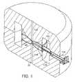
- FIG. 1is a perspective sectioned diagram showing the basic structure of a high-field synchrocyclotron, omitting the coil/cryostat assembly.
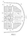
- FIG. 2is a sectional illustration of the ferromagnetic material and the magnet coils for the high-field synchrocyclotron.
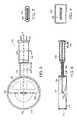
- FIG. 3is an illustration of a pair of iron tip rings that extend from respective pole wings and that share a common central axis of orientation, with the gap there between extended in the drawing to better facilitate illustration.
- FIG. 4is a sectional illustration of features of the high-field, split-pair superconducting coil set.
- FIG. 5is a sectional illustration of the synchrocyclotron beam chamber, accelerating dee and resonator.
- FIG. 6is a sectional illustration of the apparatus of FIG. 5 , with the section taken along the longitudinal axis shown in FIG. 5 .
- FIG. 7is a sectional illustration taken through the resonator conductors in the apparatus of FIG. 5 at double the scale in size.
- FIG. 8is a sectional illustration taken through the resonator outer return yoke in the apparatus of FIG. 5 at double the scale in size.
- FIG. 9shows an alternative RF configuration using two dees and axially directed RF ports.
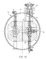
- FIG. 10is a sectional illustration of a magnet structure, viewed in a plane in which the central axis of the magnet structure lies.
- FIG. 11is a sectional illustration of the magnet structure of FIG. 10 , viewed in a plane normal to the central axis and parallel to the acceleration plane.
- FIG. 12is a sectional illustration of the cold-mass structure, including the coils and the bobbin.
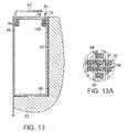
- FIG. 13is a sectional illustration, showing the interior structure of a coil.
- FIG. 13Ais a magnified view of the section shown in FIG. 13 .
- FIG. 14is a sectional illustration of an integral magnetic shield having a contorted shape.
- FIG. 15is a perspective view of a section of the integral magnetic shield of FIG. 14 .
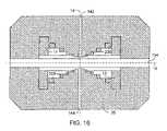
- FIG. 16is a sectional illustration of the basic form of a magnet structure (with particular details omitted) that includes additional active coils in the acceleration chamber to shape the magnetic field at the acceleration plane.
- synchrocyclotronse.g., in isochronous cyclotrons and in other applications employing superconductors and/or for generating high magnetic fields
- this descriptionbegins with an explanation of underlying principles and features in the context of a synchrocyclotron.
- Synchrocyclotronsin general, may be characterized by the charge, Q, of the ion species; by the mass, M, of the accelerated ion; by the acceleration voltage, V 0 ; by the final energy, E; by the final radius, R, from a central axis; and by the central field, B 0 .
- the parameters, B 0 and Rare related to the final energy such that only one need be specified.
- the high-field superconducting synchrocyclotron of this discourseincludes a number of important features and elements, which function, following the principles of synchronous acceleration, to create, accelerate and extract ions of a particular Q, M, V 0 , E and B 0 .
- the central field aloneis raised and all other key parameters held constant, it is seen that the final radius of the accelerator decreases in proportion; and the synchrocyclotron becomes more compact.
- This increasing overall compactness with increasing central field, B 0can be characterized approximately by the final radius to the third power, R 3 , and is shown in the table below, in which a large increase in field results in a large decrease in the approximate volume of the synchrocyclotron.
- the final column in the above chartrepresents the volume scaling, wherein R 1 is the pole radius of 2.28 m, where B 0 is 1 Tesla; and R is the corresponding radius for the central field, B 0 , in each row.
- M⁇ iron V
- synchrocyclotronOne factor that changes significantly with this increase in central field, B 0 , is the cost of the synchrocyclotron, which will decrease. Another factor that changes significantly is the portability of the synchrocyclotron; i.e., the synchrocyclotron should be easier to relocate; for example, the synchrocyclotron can then be placed upon a gantry and moved around a patient for cancer radiotherapy, or the synchrocyclotron can be placed upon a cart or a truck for use in mobile applications, such as gateway-security-screening applications utilizing energetic beams of point-like particles.
- sizei.e., all of the features and essential elements of the synchrocyclotron and the properties of the ion acceleration also decrease substantially in size with increasing field. Described herein is a manner in which the synchrocyclotron may be significantly decreased in overall size (for a fixed ion species and final energy) by raising the magnetic field using superconducting magnetic structures that generate the fields.
- the synchrocyclotronWith increasing field, B 0 , the synchrocyclotron possesses a structure for generating the required magnetic energy for a given energy, E; charge, Q; mass, M; and accelerating voltage, V 0 .
- This magnetic structureprovides stability and protection for the superconducting elements of the structure, mitigates the large electromagnetic forces that also occur with increasing central field, B 0 , and provides cooling to the superconducting cold mass, while generating the required total magnetic field and field shape characteristic of synchronous particle acceleration.
- the yoke 36 , dee 48 and resonator structure 174 of a 9.2-Tesla, 250-MeV-proton superconducting synchrocyclotron having Nb 3 Sn-conductor-based superconducting coils (not shown) operating at peak fields of 11.2 Teslaare illustrated in FIG. 1 .
- This synchrocyclotron solutionwas predicated by a new scaling method from the solution obtained at 5.5 Tesla in X. Wu, “Conceptual Design and Orbit Dynamics in a 250 MeV Superconducting Synchrocyclotron” (1990) (Ph.D. Dissertation, Michigan State University); it is believed that the Wu thesis suggested the highest central field (B 0 ) level in a design for a synchrocyclotron up to that point in time—provided in a detailed analysis effort or demonstrated experimentally in operation.
- the new ion speciescan be the same as in the particular examples provided herein (i.e., the scaling laws are more general than just 250 MeV and protons); the charge, Q, and the mass, M, can, in fact, be different; and a scaling solution can be determined for a new species with a different Q and M.
- the ionsare carbon atoms stripped of electrons for a +6 charge (i.e., 12 C 6+ ); in this embodiment, less extreme field shaping would be needed (e.g., the profiles of the pole surfaces would be flatter) compared with a lower-mass, lower-charge particle.
- the new scaled energy, Emay be different from the previous final energy.
- B 0can also be changed. With each of these changes, the synchrocyclotron mode of acceleration can be preserved.
- the ferromagnetic iron yoke 36surrounds the accelerating region in which the beam chamber, dee 48 and resonator structure 174 reside; the yoke 36 also surrounds the space for the magnet cryostat, indicated by the upper-magnet cryostat cavity 118 and by the lower-magnet cryostat cavity 120 .
- the ferromagnetic iron core and return yoke 36is designed as a split structure to facilitate assembly and maintenance; and it has an outer radius less than 35 inches ( ⁇ 89 cm), a total height less than 40 inches ( ⁇ 100 cm), and a total mass less than 25 tons ( ⁇ 23,000 kg).
- the yoke 36is maintained at room temperature.
- FIG. 1For clarity, numerous other features of the ferromagnetic iron yoke structure 36 for high-field synchrocyclotron operation are not shown in FIG. 1 . These features are now shown in FIG. 2 .
- the structure of the synchrocyclotronapproaches 360-degree rotational symmetry about its main axis 16 , allowing for discrete ports and other discrete features at particular locations, as illustrated elsewhere herein.
- the synchrocyclotronalso has a median acceleration plane 18 , which is the mirror-symmetry plane for the ferromagnetic yoke 36 , and the mid-plane of the split coil pair 12 and 14 ; the median acceleration plane also is the vertical center of the beam chamber (defined between the poles 38 and 40 ), dee 48 and resonator structure 174 and of the particle trajectories during acceleration.
- the ferromagnetic yoke structure 36 of the high-field synchrocyclotronis composed of multiple elements.
- the magnet poles 38 and 40define an upper central passage 142 and a lower central passage 144 , aligned about the central axis 16 of the synchrocyclotron and each with a diameter of about 3 inches ( ⁇ 7.6 cm), which provide access for insertion and removal of the ion source, which is positioned on the main axis 16 at the median plane 18 in the central region of the acceleration chamber 46 .
- a detailed magnetic field structureis utilized to provide stable acceleration of the ions.
- the detailed magnetic field configurationis provided by shaping of the ferromagnetic iron yoke 36 , through shaping of the upper and lower pole tip contours 122 and 124 and upper and lower pole contours 126 and 128 for initial acceleration and by shaping upper and lower pole contours 130 and 132 for high-field acceleration.
- the maximum pole gap between the upper and lower pole contours 130 and 132is more than twice the size of the maximum pole gap between the upper and lower pole contours 126 and 128 and more than five times the size of the minimum pole gap at the upper and lower pole tip contours 122 and 124 .
- the slopes of the upper and lower pole tip contours 122 and 124are steeper than the slopes of the adjacent upper and lower pole contours 126 and 128 for initial acceleration.
- the slopes of the upper and lower pole contours 130 and 132 for high-field accelerationagain substantially increase (for contour 130 ) and decrease (for contour 132 ) to increase the rate at which the pole gap expands as a function of increasing radial distance from the central (main) axis 16 .
- the slopes of the surfaces of the upper and lower pole wings 134 and 136are even steeper than (and inverse to) the slopes of the upper and lower pole contours 130 and 132 , such that the size of the pole gap quickly drops (by a factor of more than five) with increasing radius between the pole wings 134 and 136 . Accordingly, the structure of the pole wings 134 and 136 provides substantial shielding from the magnetic fields generated by the coils 12 and 14 toward the outer perimeter of the acceleration chamber by trapping inner field lines proximate to the coils 12 and 14 to thereby sharpen the drop off of the field beyond those trapped field lines.
- the furthest gapwhich is between the junction of the wing 134 with surface 130 and the junction of the wing 136 and surface 132 is about 37 cm.
- This gapthen abruptly narrows (at an angle between 80 and 90°—e.g., at an angle of about 85°—to the median acceleration plane 18 ) to about 6 cm between the tips 138 and 140 .
- the gap between the pole wings 134 and 136can be less than one-third (or even less than one-fifth) the size of the furthest gap between the poles.
- the gap between the coils 12 and 14in this embodiment, is about 10 cm.
- the coils 12 and 14include more amp-turns and are split further apart from each other and are also positioned closer to the respective wings 134 and 136 .
- the pole gapis increased between contours 126 and 128 and between contours 130 and 132 ), while the pole gap is narrowed between the perimeter tips 138 and 140 (e.g., to about 3.8 cm in a magnet structure designed for a 14 Tesla field) and between the center tips 122 and 124 .
- the thickness of the wings 134 and 136(measured parallel to the acceleration plane 18 ) is increased.
- the applied voltageis lower, and the orbits of the ions are more compact and greater in number; the axial and radial beam spread is smaller.
- contour changesare representative only—as for each high-field-synchrocyclotron scaling solution, there may be a different number of pole taper changes to accommodate phase-stable acceleration and weak focusing; the surfaces may also have smoothly varying contours.
- Ionshave an average trajectory in the form of a spiral expanding along a radius, r.
- the ionsalso undergo small orthogonal oscillations around this average trajectory. These small oscillations about the average radius are known as betatron oscillations, and they define particular characteristics of accelerating ions.
- the upper and lower pole wings 134 and 136sharpen the magnetic field edge for extraction by moving the characteristic orbit resonance, which sets the final obtainable energy closer to the pole edge.
- the upper and lower pole wings 134 and 136additionally serve to shield the internal acceleration field from the strong split coil pair 12 and 14 .
- Conventional regenerative synchrocyclotron extraction or self-extractionis accommodated by allowing additional localized pieces of ferromagnetic upper and lower iron tips 138 and 140 to be placed circumferentially around the face of the upper and lower pole wings 134 and 136 to establish a sufficient non-axi-symmetric edge field.
- the iron tips 138 and 140are separated from the respective upper and lower pole wings 134 and 136 via a gap there between; the iron tips 138 and 140 can thereby be incorporated inside the beam chamber, whereby the chamber walls pass through that gap.
- the iron tips 138 and 140will still be in the magnetic circuit, though they will be separately fixed.
- the iron tips 138 and 140 or the pole wings 134 and 136can be non-symmetrical about the central axis 16 , with the inclusion, e.g., of slots 202 and extensions 204 to respectively decrease and increase the magnetic field at those locales.
- the iron tips 138 and 140are not continuous around the circumference of the poles 38 and 40 , but rather are in the form of distinct segments separated by gaps, wherein lower local fields are generated at the gaps.
- differing local fieldsare generated by varying the composition of the iron tips 138 and 140 or by incorporating selected materials having distinct magnetic properties at different positions around the circumference of the tips 138 and 140 .
- composition elsewhere in the magnetic yokecan also be varied (e.g., by providing different materials having distinct magnetic properties) to shape the magnetic field (i.e., to raise or lower the field), as desired (e.g., to provide weak focusing and phase stability for the accelerated ions), in particular regions of the median acceleration plane.
- Multiple radial passages 154 defined in the ferromagnetic iron yoke 36provide access across the median plane 18 of the synchrocyclotron.
- the median-plane passages 154are used for beam extraction and for penetration of the resonator inner conductor 186 and resonator outer conductor 188 (see FIG. 5 ).
- An alternative method for access to the ion-accelerating structure in the pole gap volumeis through upper axial RF passage 146 and through lower axial RF passage 148 .
- the cold-mass structure and cryostatinclude a number of penetrations for leads, cryogens, structural supports and vacuum pumping, and these penetrations are accommodated within the ferromagnet core and yoke 36 through the upper-pole cryostat passage 150 and through the lower-pole cryostat passage 152 .
- the cryostatis constructed of a non-magnetic material (e.g., an INCONEL nickel-based alloy, available from Special Metals Corporation of Huntington, W. Va., USA)
- the ferromagnetic iron yoke 36comprises a magnetic circuit that carries the magnetic flux generated by the superconducting coils 12 and 14 to the acceleration chamber 46 .
- the magnetic circuit through the yoke 36also provides field shaping for synchrocyclotron weak focusing at the upper pole tip 102 and at the lower pole tip 104 .
- the magnetic circuitalso enhances the magnet field levels in the acceleration chamber by containing most of the magnetic flux in the outer part of the magnetic circuit, which includes the following ferromagnetic yoke elements: upper pole root 106 with corresponding lower pole root 108 , the upper return yoke 110 with corresponding lower return yoke 112 .
- the ferromagnetic yoke 36is made of a ferromagnetic substance, which, even though saturated, provides the field shaping in the acceleration chamber 46 for ion acceleration.
- the upper and lower magnet cryostat cavities 118 and 120contain the upper and lower superconducting coils 12 and 14 as well as the superconducting cold-mass structure and cryostat surrounding the coils, not shown.
- the location and shape of the coils 12 and 14are also important to the scaling of a new synchrocyclotron orbit solution for a given E, Q, M and V 0 , when B 0 is significantly increased.
- the bottom surface 114 of the upper coil 12faces the opposite top surface 116 of the bottom coil 14 .
- the upper-pole wing 134faces the inner surface 61 of the upper coil 12 ; and, similarly, the lower-pole wing 136 faces the inner surface 62 of the lower coil 14 .
- An integral external shield 60 of ferromagnetic materialmay be used to minimize the magnetic fields away from the synchrocyclotron.
- the shield 60may be in the form of layers or may have a convoluted surface for additional local shielding, and may have passages for synchrocyclotron services and for the final external-beam-transport system away from the cyclotron.
- Synchrocyclotronsare a member of the circular class of particle accelerators.
- the beam theory of the circular particle acceleratorsis well-developed, based upon the following two key concepts: equilibrium orbits and betatron oscillations around equilibrium orbits.
- the principle of equilibrium orbits (EOs)can be described as follows:
- nthe weak-focusing field index parameter, n, noted above, is defined as follows:
- n- r B ⁇ d B d r , where r is the radius of the ion (Q, M) from the main axis 16 ; and B is the magnitude of the axial magnetic field at that radius.
- the weak-focusing field index parameter, nis in the range from zero to one across the entirety of the acceleration chamber (with the possible exception of the central region of the chamber proximate the main central axis 16 , where the ions are introduced and where the radius is nearly zero) to enable the successful acceleration of ions to full energy in the synchrocyclotron, where the field generated by the coils dominates the field index.
- a restoring forceis provided during acceleration to keep the ions oscillating with stability about the mean trajectory.
- the synchrocyclotronhas a field that decreases with radius to match the field index required for acceleration.
- the field indexis known, one can specify, to some level of precision, an electromagnetic circuit including the positions and location of many of the features, as indicated in FIG. 2 , to the level at which further detailed orbit and field computations can provide an optimized solution. With such a solution in hand, one can then scale that solution to a parameter set (B 0 , E, Q, M and V 0 ).
- This decreasing frequency with increasing energy in a synchrocyclotronis the basis for the synchrocyclotron acceleration mode of circular particle accelerators, and gives rise to an additional decrease in field with radius in addition to the field index change required for the axial restoring force.
- the voltage, V, across the gapis greater than a minimum voltage, V min , needed to provide phase stability; at V min , the particles have an energy at the gap that allows them to gain more energy when crossing the next gap.
- synchrocyclotron accelerationinvolves the principle of phase stability, which may be characterized in that the available acceleration voltage nearly always exceeds the voltage required for ion acceleration from the center of the accelerator to full energy near the outer edge.
- the radius, r, of the iondecreases, the accelerating electric field must increase, suggesting that there may by a practical limit to acceleration voltages with increasing magnetic field, B.
- the field index, nthat may be determined from these principle effects, among others, can be used to derive the radial variation in the magnetic field for acceleration.
- This B-versus-r profilecan further be parameterized by dividing the magnetic fields in the data set by the actual magnetic-field value needed at full energy and also by dividing the corresponding radius values in this B-versus-r data set by the radius at which full energy is achieved.
- the properties of superconducting coilsare further considered, below, in order to further develop a higher-field synchrocyclotron using superconducting coils.
- a number of different kinds of superconductorscan be used in superconducting coils; and among many important factors for engineering solutions, the following three factors are often used to characterize superconductors: magnetic field, current density and temperature.
- B maxis the maximum magnetic field that may be supported in the superconducting filaments of the superconducting wire in the coils while maintaining a superconducting state at a certain useful engineering current density, J e , and operating temperature, T op .
- an operating temperature, T opof 4.5K is frequently used for superconducting coils in magnets, such as those proposed for superconducting synchrocyclotrons, particularly in the high-field superconducting synchrocyclotrons discussed herein.
- an engineering current density, J eof 1000 A/mm 2 is reasonably representative. The actual ranges of operating temperature and current densities are broader than these values.
- the superconducting material, NbTiis used in superconducting magnets and can be operated at field levels of up to 7 Tesla at 1000 A/mm 2 and 4.5 K, while Nb 3 Sn can be operated at field levels up to approximately 11 Tesla at 1000 A/mm 2 and 4.5K.
- NbTiis also possible to maintain a temperature of 2K in superconducting magnets by a process known as sub-cooling; and, in this case, the performance of NbTi would reach operating levels of about 11 Tesla at 2K and 1000 A/mm 2 , while Nb 3 Sn could reach about 15 Tesla at 2K and 1000 A/mm 2 .
- superconducting coils made of NbTi and Nb 3 Sn conductors and operating at 4.5Kspan a range of operating field levels from low fields in synchrocyclotrons to fields in excess of 10 Tesla. Decreasing the operating temperature further to 2K expands that range to operating magnetic field levels of at least 14 Tesla.
- Superconducting coilsare also characterized by the level of magnetic forces in the windings and by the desirability of removing the energy quickly should, for any reason, a part of the winding become normal conducting at full operating current. The removal of energy is known as a magnet quench.
- the coil setincludes a split coil pair, with upper superconducting coil 12 and lower superconducting coil 14 .
- the upper 12 and lower 14 superconducting coilsare axially wound with alternating superconductor and insulating elements.
- Several types or grades of superconductorcan be used, with different composition and characteristics.
- each superconducting coil 12 and 14can have multiple segments separated by boundaries 168 and 170 . Although three segments are illustrated in FIG. 4 , this is only one embodiment, and fewer or more segments may be used.
- the upper and lower coils 12 and 14are within a low-temperature-coil mechanical containment structure referred to as the bobbin 20 .
- the bobbin 20supports and contains the coils 12 and 14 in both radial and axial directions, as the upper and lower coils 12 and 14 have a large attractive load as well as large radial outward force.
- the bobbin 20provides axial support for the coils 12 and 14 through their respective surfaces 114 and 116 .
- multiple radial passages 172are defined in and through the bobbin 20 .
- multiple attachment structurescan be provided on the bobbin 20 so as to offer radial axial links for holding the coil/bobbin assembly in a proper location.
- Point 156 in the upper superconducting coil 12 and point 158 in the lower superconducting coil 14indicate approximate regions of highest magnetic field; and this field level sets the design point for the superconductor chosen, as discussed above.
- crossed region 164 in the upper superconducting coil 12 and crossed region 166 in the lower superconducting coil 14indicate regions of magnetic field reversal; and in these cases, the radial force on the windings are directed inward and is to be mitigated.
- Regions 160 and 162indicate zones of low magnetic field or nearly zero overall magnetic field level, and they exhibit the greatest resistance to quenching.
- the compact high-field superconducting cyclotronincludes elements for phase-stable acceleration, which are shown in FIGS. 5-8 .
- FIGS. 5 and 6provide a detailed engineering layout of one type of beam-accelerating structure, with a beam chamber 176 and resonator 174 , for the 9.2 Tesla solution of FIG. 1 , where the chamber 176 is located in the pole gap space.
- the elevation view of FIG. 5shows only one of the dees 48 used for accelerating the ions, while the side view shows that this dee 48 is split above and below the median plane for the beam to pass within during acceleration.
- the dee 48 and the ionsare in a volume under vacuum and defined by the beam chamber 176 , which includes a beam-chamber base plate 178 .
- the acceleration-gap-defining aperture 180establishes the electrical ground plane. The ions are accelerated by the electric field across the acceleration gap 182 between the dee 48 and the acceleration-gap ground-plane defining aperture 180 .
- the dees 48are connected to a resonator inner conductor 186 and to a resonator outer conductor 188 through dee-resonator connector 184 .
- the outer resonator conductor 188is connected to the cryostat 200 (shown in FIG. 9 ) of the high-field synchrocyclotron, a vacuum boundary maintained by the connection.
- the resonator frequencyis varied by an RF rotating capacitor (not shown), which is connected to the accelerating dee 48 and the inner and outer conductors 186 and 198 through the resonator outer conductor return yoke 190 through the coupling port 192 .
- the poweris delivered to the RF resonant circuit through RF-transmission-line coupling port 194 .
- an alternative structure with two dees and axial RF resonator elementsis incorporated into the compact high-field superconducting synchrocyclotron, as shown schematically in FIG. 9 .
- Such a two-dee systemmay allow for increased acceleration rates or reduced voltages, V 0 .
- two dees 48 and 49are used; the dees 48 and 49 are separated into halves on opposite sides of the median plane and are energized by upper axial resonators 195 and 196 and by lower axial resonators 197 and 198 , which are energized by external RF power sources (in addition to radial power feeds through passages 154 , illustrated in FIG. 2 ).
- FIG. 9also shows how the coil cryostat 200 is fitted into the ferromagnetic yoke structure 36 .
- FIGS. 10 and 11A more complete and detailed illustration of a magnet structure 10 for particle acceleration is illustrated in FIGS. 10 and 11 .
- the magnet structure 10can be used, e.g., in a compact synchrocyclotron (e.g., in a synchrocyclotron that otherwise shares the features of the synchrocyclotron disclosed in U.S. Pat. No. 4,641,057), in an isochronous cyclotron, and in other types of cyclotron accelerators in which ions (such as protons, deuterons, alpha particles, and other ions) can be accelerated.
- ionssuch as protons, deuterons, alpha particles, and other ions
- a cold-mass structure 21which includes the pair of circular coils 12 and 14 .
- the pair of circular coils 12 and 14are mounted inside respective copper thermal shields 78 maintained under vacuum with intimate mechanical contact between the coils 12 and 14 and the copper thermal shields 78 .
- a pressurized bladder 80that applies a radial inward force to counter the very high hoop tension force acting on each coil 12 / 14 during operation.
- the coils 12 and 14are symmetrically arranged about a central axis 16 equidistant above and below an acceleration plane 18 in which the ions can be accelerated.
- Each coil 12 / 14includes a continuous path of conductor material that is superconducting at the designed operating temperature, generally in the range of 4-6K, but also may be operated below 2K, where additional superconducting performance and margin is available.
- the radius of each coilis about 17.25 inches ( ⁇ 43.8 cm).
- the coils 12 and 14comprise superconductor cable or cable-in-channel conductor with individual cable strands 82 having a diameter of 0.6 mm and wound to provide a current carrying capacity of, e.g., between 2 million to 3 million total amps-turns.
- each strand 82has a superconducting current-carrying capacity of 2,000 amperes
- 1,500 windings of the strandare provided in the coil to provide a capacity of 3 million amps-turns in the coil.
- the coilwill be designed with as many windings as are needed to produce the number of amps-turns needed for a desired magnetic field level without exceeding the critical current carrying capacity of the superconducting strand.
- the superconducting materialcan be a low-temperature superconductor, such as niobium titanium (NbTi), niobium tin (Nb 3 Sn), or niobium aluminum (Nb 3 Al); in particular embodiments, the superconducting material is a type II superconductor—in particular, Nb 3 Sn having a type A15 crystal structure.
- High-temperature superconductorssuch as Ba 2 Sr 2 Ca 1 Cu 2 O 8 , Ba 2 Sr 2 Ca 2 Cu 3 O 10 , or YBa 2 Cu 3 O 7-x , may also be used.
- the cabled strands 82are soldered into a U-shaped copper channel 84 to form a composite conductor 86 .
- the copper channel 84provides mechanical support, thermal stability during quench; and a conductive pathway for the current when the superconducting material is normal (i.e., not superconducting).
- the composite conductor 86is then wrapped in glass fibers and then wound in an outward overlay.
- Strip heaters 88 formed, e.g., of stainless steelcan also be inserted between wound layers of the composite conductor 86 to provide for rapid heating when the magnet is quenched and also to provide for temperature balancing across the radial cross-section of the coil after a quench has occurred, to minimize thermal and mechanical stresses that may damage the coils.
- a winding insulation layer 96 formed of epoxy-impregnated glass fiberslines the interior of the copper thermal shield 78 and encircles the coil 12 .
- the coilis formed by encasing a wound strand of tin wires in a matrix of niobium powder.
- the wound strand and matrixare then heated to a temperature of about 650° C. for 200 hours to react the tin wires with the niobium matrix and thereby form Nb 3 Sn.
- each Nb 3 Sn strand in the cablemust carry a portion of the total electric current with sufficient current margin at the operating magnetic field and temperature to maintain the superconducting state.
- the specification of the copper channel cross-section and epoxy composite matrixallows the high field coil to maintain its superconducting state under greater mechanical stresses that occur in such compact coils.
- Nb 3 Sn conductorsare brittle and may be damaged and lose some superconducting capability unless the stress state through all operations is properly limited.
- the wind-and-react method followed by the formation of an epoxy-composite mechanical structure around the windingsenables these Nb 3 Sn coils to be used in other applications where superconductors are used or can be used, but where Nb 3 Sn may not otherwise be suitable due to the brittleness of standard Nb 3 Sn coils in previous embodiments.
- the copper shields, with the coils 12 and 14 contained therein,are mounted in a bobbin 20 formed of a high-strength alloy, such as stainless steel or an austenitic nickel-chromium-iron alloy (commercially available as INCONEL 625 from Special Metals Corporation of Huntington, W. Va., USA).
- the bobbin 20intrudes between the coils 12 and 14 , but is otherwise outside the coils 12 and 14 .
- the top and bottom portions of the bobbin 20(per the orientation of FIG. 12 ), which are outside the coils, each has a thickness (measured horizontally, per the orientation of FIG. 12 ) approximately equal to the thickness of the coil 12 / 14 .
- the cold-mass structure 21including the coils 12 and 14 and the bobbin 20 , is encased in an insulated and evacuated stainless steel or aluminum shell 23 , called a cryostat, which can be mounted inside the iron pole and yoke 36 .
- the cold-mass structure 21circumscribes (i.e., at least partially defines) a space for an acceleration chamber 46 (see FIG. 11 ) for accelerating ions and a segment of the central axis 16 extending across the acceleration chamber 46 .
- the magnet structure 10also includes an electrically conducting wire 24 (e.g., in the form of a cable) encircling each coil 12 / 14 (e.g., in a spiral around the coil, just a small portion of which is illustrated in FIG. 11 ) for quenching the coil 12 / 14 as it goes “normal” due to increasing temperature.
- a voltage or current sensoris also coupled with the coils 12 and 14 to monitor for an increase in electrical resistance in either coil 12 / 14 , which would thereby signify that a portion of the coil 12 / 14 is no longer superconducting.
- cryocoolers 26which can utilize compressed helium in a Gifford-McMahon refrigeration cycle or which can be of a pulse-tube cryocooler design, are thermally coupled with the cold-mass structure 21 .
- the couplingcan be in the form of a low-temperature superconductor (e.g., NbTi) current lead in contact with the coil 12 / 14 .
- the cryocoolers 26can cool each coil 12 / 14 to a temperature at which it is superconducting.
- each coil 12 / 14can be maintained in a dry condition (i.e., not immersed in liquid helium or other liquid refrigerant) during operation, and no liquid coolant need be provided in or about the cold-mass structure 21 either for cool-down of the cold mass or for operating of the superconducting coils 12 / 14 .
- a second pair of cryocoolers 27which can be of the same or similar design to cryocoolers 26 , are coupled with the current leads 37 and 58 to the coils 12 and 14 .
- High-temperature current leads 37are formed of a high-temperature superconductor, such as Ba 2 Sr 2 Ca 1 Cu 2 O 8 or Ba 2 Sr 2 Ca 2 Cu 3 O 10 , and are cooled at one end by the cold heads 33 at the end of the first stages of the cryocoolers 27 , which are at a temperature of about 80 K, and at their other end by the cold heads 35 at the end of the second stages of the cryocoolers 27 , which are at a temperature of about 4.5 K.
- the high-temperature current leads 37are also conductively coupled with a voltage source.
- Lower-temperature current leads 58are coupled with the higher-temperature current leads 37 to provide a path for electrical current flow and also with the cold heads 35 at the end of the second stages of the cryocoolers 27 to cool the low-temperature current leads 58 to a temperature of about 4.5 K.
- Each of the low-temperature current leads 58also includes a wire 92 that is attached to a respective coil 12 / 14 ; and a third wire 94 , also formed of a low-temperature superconductor, couples in series the two coils 12 and 14 .
- Each of the wirescan be affixed to the bobbin 20 .
- electrical currentcan flow from an external circuit possessing a voltage source, through a first of the high-temperature current leads 37 to a first of the low-temperature current leads 58 and into coil 12 ; the electrical current can then flow through the coil 12 and then exit through the wire joining the coils 12 and 14 . The electrical current then flows through the coil 14 and exits through the wire of the second low-temperature current lead 58 , up through the low-temperature current lead 58 , then through the second high-temperature current lead 37 and back to the voltage source.
- the cryocoolers 29 and 31allow for operation of the magnet structure away from sources of cryogenic cooling fluid, such as in isolated treatment rooms or also on moving platforms.
- the pair of cryocoolers 26 and 27permit operation of the magnet structure with only one cryocooler of each pair having proper function.
- At least one vacuum pump(not shown) is coupled with the acceleration chamber 46 via the resonator 28 in which a current lead for the RF accelerator electrode is also inserted.
- the acceleration chamber 46is otherwise sealed, to enable the creation of a vacuum in the acceleration chamber 46 .
- Radial-tension links 30 , 32 and 34are coupled with the coils 12 and 14 and bobbin 20 in a configuration whereby the radial-tension links 30 , 32 and 34 can provide an outward hoop force on the bobbin 20 at a plurality of points so as to place the bobbin 20 under radial outward tension and keep the coils 12 and 14 centered (i.e., substantially symmetrical) about the central axis 16 .
- the tension links 30 , 32 and 34provide radial support against magnetic de-centering forces whereby the cold mass approaching the iron on one side sees an exponentially increasing force and moves even closer to the iron.
- the radial-tension links 30 , 32 and 34comprise two or more elastic tension bands 64 and 70 with rounded ends joined by linear segments (e.g., in the approximate shape of a conventional race or running track) and have a right circular cross-section.
- the bandsare formed, e.g., of spiral wound glass or carbon tape impregnated with epoxy and are designed to minimize heat transfer from the high-temperature outer frame to the low-temperature coils 12 and 14 .
- a low-temperature band 64extends between support peg 66 and support peg 68 .
- the lowest-temperature support peg 66which is coupled with the bobbin 20 , is at a temperature of about 4.5 K, while the intermediate peg 68 is a temperature of about 80 K.
- a higher-temperature band 70extends between the intermediate peg 68 and a high-temperature peg 72 , which is at a near-ambient temperature of about 300 K.
- An outward forcecan be applied to the high-temperature peg 72 to apply additional tension at any of the tension links 30 , 32 and 34 to maintain centering as various de-centering forces act on the coils 12 and 14 .
- the pegs 66 , 68 , and 72can be formed of stainless steel.
- tension linkscan be attached to the coils 12 and 14 along a vertical axis (per the orientation of FIGS. 10 and 12 ) to counter an axial magnetic decentering force in order to maintain the position of the coils 12 and 14 symmetrically about the mid-plane 18 .
- the coils 12 and 14will be strongly attracted to each other, though the thick bobbin 20 section between the coils 12 and 14 will counterbalance those attractive forces.
- the set of radial and axial tension linkssupport the mass of the coils 12 and 14 and bobbin 20 against gravity in addition to providing the required centering force.
- the tension linksmay be sized to allow for smooth or step-wise three-dimensional translational or rotational motion of the entire magnet structure at a prescribed rate, such as for mounting the magnet structure on a gantry, platform or car to enable moving the proton beam in a room around a fixed targeted irradiation location. Both the gravitational support and motion requirements are tension loads not in excess of the magnetic decentering forces.
- the tension linksmay be sized for repetitive motion over many motion cycles and years of motion.
- a magnetic yoke 36 formed of low-carbon steelsurrounds the coils 12 and 14 and cryostat 23 .
- Pure ironmay be too weak and may possess an elastic modulus that is too low; consequently, the iron can be doped with a sufficient quantity of carbon and other elements to provide adequate strength or to render it less stiff while retaining the desired magnetic levels.
- the yoke 36circumscribes the same segment of the central axis 16 that is circumscribed by the coils 12 and 14 and the cryostat 23 .
- the radius (measured from the central axis) at the outer surfaces of the yoke 36can be about 35 inches ( ⁇ 89 cm) or less.
- the yoke 36includes a pair of poles 38 and 40 having tapered inner surfaces 42 and 44 that define a pole gap 47 between the poles 38 and 40 and across the acceleration chamber 46 .
- the profiles of those tapered inner surfaces 42 and 44are a function of the position of the coils 12 and 14 .
- the tapered inner surfaces 42 and 44are shaped such that the pole gap 47 (measured as shown by the reference line in FIG. 10 ) expands over an inner stage defined between opposing surfaces 42 as the distance from the central axis 16 increases and decreases over an outer stage defined between opposing surfaces 44 as the distance from the central axis 16 further increases.
- the inner stageestablishes a correct weak focusing requirement for ion (e.g., proton) acceleration when used, e.g., in a synchrocyclotron for proton acceleration, while the outer stage is configured to reduce pole diameter by increasing energy gain versus radius, which facilitates extraction of ions from the synchrocyclotron as the ions approach the perimeter of the acceleration chamber 46 .
- ione.g., proton
- the pole profile thus describedhas several important acceleration functions, namely, ion guiding at low energy in the center of the machine, capture into stable acceleration paths, acceleration, axial and radial focusing, beam quality, beam loss minimization, attainment of the final desired energy and intensity, and the positioning of the final beam location for extraction.
- accelerationion guiding at low energy in the center of the machine
- capture into stable acceleration pathsacceleration, axial and radial focusing, beam quality, beam loss minimization, attainment of the final desired energy and intensity, and the positioning of the final beam location for extraction.
- the simultaneous attainment of weak focusing and acceleration phase stabilityis achieved.
- the expansion of the pole gap over the first stageprovides for sufficient weak focusing and phase stability, while the rapid closure of the gap over the outer stage is responsible for maintaining weak focusing against the deleterious effects of the strong superconducting coils, while properly positioning the full energy beam near the pole edge for extraction into the extraction channel.
- the rate at which the gap opening increases with increasing radius over the inner stageis made greater, while the gap is closed over the outer stage to a narrower separation distance.
- this set of simultaneous objectivescan be accomplished by substituting a nested set of additional superconducting coils 206 (e.g., superconducting at a temperature of at least 4.5K) in the acceleration chamber in place of the tapered surfaces of the poles and having currents in those nested coils optimized to match the field contribution of the poles to the overall acceleration field, as shown in FIG. 16 .
- These radially distributed coils 206can be embedded in the yoke 26 or mounted (e.g., bolted) to the yoke 26 . At least one of these additional superconducting coils 206 generates a magnetic field in local opposition to the two primary superconducting coils 12 and 14 .
- the yoke 36also is cooled (e.g., by one or more cryocoolers).
- an insulated structurecan be provided through the radial median-plane passages 154 , with the acceleration chamber contained within this insulated structure so that the acceleration chamber can be maintained at a warm temperature.
- the opposing fieldis generated in the internal coils 206 by passing current through the additional magnetic coils 206 in the opposite direction from which current is passed in the primary coils 12 and 14 .
- Use of the additional active coils 206 in the acceleration chambercan be particularly advantageous in contexts where the field in the acceleration plane 18 is greater than 12 Tesla and where more field compensation is accordingly needed to maintain the decrease in the field with radius while maintaining weak focusing and phase stability.
- the higher-field magnet structureswill have smaller external radii.
- a magnet structure for producing a magnetic field of 14 Tesla in the median acceleration plane 18can be constructed with the yoke having an outer radius of just over one foot (i.e., just over 30 cm).
- the yoke 36can be omitted, and the field can be generated entirely by superconducting coils 12 , 14 and 206 .
- the iron in the yoke 36is replaced with another strong ferromagnetic material, such as gadolinium, which has a particularly high saturation magnetism (e.g., up to about 3 Tesla).
- the iron yokeprovides sufficient clearance for insertion of a resonator structure 174 including the radiofrequency (RF) accelerator electrodes 48 (also known as “dees”) formed of a conductive metal.
- the electrodes 48are part of a resonator structure 174 that extends through the sides of the yoke 36 and passes through the cryostat 23 and between the coils 12 and 14 .
- the accelerator electrodes 48include a pair of flat semi-circular parallel plates that are oriented parallel to and above and below the acceleration plane 18 inside the acceleration chamber 46 (as described and illustrated in U.S. Pat. No. 4,641,057).
- the electrodes 48are coupled with an RF voltage source (not shown) that generates an oscillating electric field to accelerate emitted ions from the ion source 50 in an expanding orbital (spiral) path in the acceleration chamber 46 .
- a dummy deecan be provided in the form of a planar sheet oriented in a plane of the central axis 16 (i.e., a plane that intersects the central axis in the orientation of FIG. 10 and extends orthogonally from the page) and having a slot defined therein to accommodate the acceleration plane for the particles.
- the dummy deecan have a configuration identical to that of the electrodes 48 , though the dummy dee would be coupled with an electrical ground rather than with a voltage source.
- the integral magnetic shield 52circumscribes the other components of the magnet structure 10 .
- the integral magnetic shield 52can be in the form of a thin sheet (e.g., having a thickness of 2 cm) of low-carbon steel. As shown in FIG. 10 , multiple sheets can be stacked together at selected locations to provide additional shielding of sensitive areas, as is evident where the sheets are triple stacked along the sides in FIG. 10 .
- the shield 52can have a tortuous shape (e.g., resembling a collapsed accordion structure), as shown in FIGS.
- the integral magnetic shield 52has a profile wherein its orientation gradually shifts back and forth between being perpendicular to and being parallel to radial vectors 56 from the central axis 16 . Each radial vector 56 would intersect the shield 52 at two or more different locations—including at a near perpendicular angle and at a near tangential angle.
- the integral magnetic shield 52is mounted at a distance from the outer surface of the magnetic yoke 36 such that it is positioned outside the contour of a 1,000-gauss magnetic-flux density generated outside the yoke 36 when a voltage is applied to the superconducting coils 12 and 14 to generate a magnetic field of 8 Tesla or more inside the acceleration chamber 46 . Accordingly, the integral magnetic shield 52 is positioned sufficiently far from the yoke 36 so that it will not be fully magnetized by the field, and it serves to suppress the far field that would otherwise be emitted from the magnet structure 10 .
- the heads 29 and 31 of the cryocoolers 26 and 27are positioned outside the integral magnetic shield 52 to shield the heads 29 and 31 from magnetic fields (which can compromise the operability of the cryocooler due to field limits in the heads 29 and 31 ). Accordingly, the integral magnetic shield 52 defines respective ports therein, through which the cryocoolers 26 and 27 can be inserted.
- cryocoolers 26are used to extract heat from the superconducting coils 12 and 14 so as to drop the temperature of each below its critical temperature (at which it will exhibit superconductivity).
- the temperature of coils formed of low-temperature superconductorsis dropped to about 4.5 K.
- a voltage(e.g., sufficient to generate 2,000 A of current through the current lead in the embodiment with 1,500 windings in the coil, described above) is applied to each coil 12 / 14 via the current lead 58 to generate a magnetic field of at least 8 Tesla within the acceleration chamber 46 when the coils are at 4.5 K.
- a voltageis applied to the coils 12 and 14 to generate a magnetic field of at least about 9 Tesla within the acceleration chamber 46 .
- the fieldcan generally be increased an additional 2 Tesla by using the cryocoolers to further drop the coil temperature to 2 K, as discussed, above.
- the magnetic fieldincludes a contribution of about 2 Tesla from the fully magnetized iron poles 38 and 40 ; the remainder of the magnetic field is produced by the coils 12 and 14 .
- This magnet structureserves to generate a magnetic field sufficient for ion acceleration.
- Pulses of ionse.g., protons
- the ion source 50e.g., the ion source described and illustrated in U.S. Pat. No. 4,641,057.
- Free protonscan be generated, e.g., by applying a voltage pulse to a cathode to cause electrons to be discharged from the cathode into hydrogen gas; wherein, protons are emitted when the electrons collide with the hydrogen molecules.
- the RF accelerator electrodes 48generate a voltage difference of 20,000 Volts across the plates.
- the electric field generated by the RF accelerator electrodes 48has a frequency matching that of the cyclotron orbital frequency of the ion to be accelerated.
- the field generated by the RF accelerator electrodes 48oscillates at a frequency of 140 MHz when the ions are nearest the central axis 16 , and the frequency is decreased to as low as 100 MHz when the ions are furthest from the central axis 16 and nearest the perimeter of the acceleration chamber 46 .
- the frequencyis dropped to offset the increase in mass of the proton as it is accelerated, as the alternating frequency at the electrodes 48 alternately attracts and repels the ions. As the ions are thereby accelerated in their orbit, the ions speed up and spiral outward.
- the ionscan be drawn out of the acceleration chamber 46 (in the form of a pulsed beam) by magnetically leading them with magnets positioned about the perimeter of the acceleration chamber 46 into a linear beam-extraction passage 60 extending from the acceleration chamber 46 through the yoke 36 and then through a gap in the integral magnetic shield 52 toward, e.g., an external target.
- the radial tension links 30 , 32 and 34are activated to impose an outward radial hoop force on the cold-mass structure 21 to maintain its position throughout the acceleration process.
- the integral magnetic shield 52contains the magnetic field generated by the coils 12 and 14 and poles 38 and 40 so as to reduce external hazards accompanying the attraction of, e.g., pens, paper clips and other metallic objects toward the magnet structure 10 , which would occur absent employment of the integral magnetic shield 52 .
- Interaction between the magnetic field lines and the integral magnetic shield 52 at various anglesis highly advantageous, as both normal and tangential magnetic fields are generated by the magnet structure 10 , and the optimum shield orientation for containing each differs by 90°.
- This shield 52can limit the magnitude of the magnetic field transmitted out of the yoke 36 through the shield 52 to less than 0.00002 Tesla.
- each superconducting coil 12 / 14during operation, will be very high (e.g., 11 Tesla) at its inner surface 62 and will drop to as low as zero at an internal point. If a quench occurs, it will likely occur at a high-field location while a low-field location may remain cold and superconducting for an extended period. This quench generates heat in the parts of the superconductor of coils 12 / 14 that are normal conducting; consequently, the edge will cease to be superconducting as its temperature rises, while a central region in the coil will remain cold and superconducting. The resulting heat differential would otherwise cause destructive stresses in the coil due to differential thermal contraction.
- 11 Teslae.g. 11 Tesla
- inductive quenchingis intended to prevent or limit this differential and thereby enable the coils 12 and 14 to be used to generate even higher magnetic fields without being destroyed by the internal stresses.
- currentmay be passed through the heater strips 88 causing the heater strip temperatures to rise well above 4.5 K and thereby locally heat the superconductors to minimize the internal temperature differentials during a quench.
- Cyclotrons incorporating the above-described apparatuscan be utilized for a wide variety of applications including proton radiation therapy for humans; etching (e.g., micro-holes, filters and integrated circuits); radioactivation of materials for materials studies; tribology; basic-science research; security (e.g., monitoring of proton scattering while irradiating target cargo with accelerated protons); production of medical isotopes and tracers for medicine and industry; nanotechnology; advanced biology; and in a wide variety of other applications in which generation of a point-like (i.e., small spatial-distribution) beam of high-energy particles from a compact source would be useful.
- etchinge.g., micro-holes, filters and integrated circuits
- radioactivation of materials for materials studiese.g., tribology; basic-science research; security (e.g., monitoring of proton scattering while irradiating target cargo with accelerated protons); production of medical isotopes and tracers for medicine
Landscapes
- Physics & Mathematics (AREA)
- Engineering & Computer Science (AREA)
- Plasma & Fusion (AREA)
- Spectroscopy & Molecular Physics (AREA)
- Optics & Photonics (AREA)
- Particle Accelerators (AREA)
- Superconductors And Manufacturing Methods Therefor (AREA)
- Soft Magnetic Materials (AREA)
Abstract
Description
| B0(Tesla) | R (m) | (R/R1)3 |
| 1 | 2.28 | 1 |
| 3 | 0.76 | 1/27 |
| 5 | 0.46 | 1/125 |
| 7 | 0.33 | 1/343 |
| 9 | 0.25 | 1/729 |
- a charge of given momentum captured by a magnetic field will transcribe an orbit;
- closed orbits represent the equilibrium condition for the given charge, momentum and energy;
- the field can be analyzed for its ability to carry a smooth set of equilibrium orbits; and
- acceleration can be viewed as transition from one equilibrium orbit to another.
Meanwhile, the weak-focusing principle of perturbation theory can be described as follows: - the particles oscillate about a mean trajectory (also, known as the central ray);
- oscillation frequencies (vr, vz) characterize motion in the radial (r) and axial (z) directions respectively;
- the magnet field is decomposed into coordinate field components and a field index (n); and vr=√{square root over (1−n)}, while vz=√{square root over (n)}; and
- resonances between particle oscillations and the magnetic field components, particularly field error terms, determine acceleration stability and losses.
where r is the radius of the ion (Q, M) from the
ω=QB/γM,
where γ is the relativistic factor for the increase in the particle mass with increasing frequency. This decreasing frequency with increasing energy in a synchrocyclotron is the basis for the synchrocyclotron acceleration mode of circular particle accelerators, and gives rise to an additional decrease in field with radius in addition to the field index change required for the axial restoring force. The voltage, V, across the gap is greater than a minimum voltage, Vmin, needed to provide phase stability; at Vmin, the particles have an energy at the gap that allows them to gain more energy when crossing the next gap. Additionally, synchrocyclotron acceleration involves the principle of phase stability, which may be characterized in that the available acceleration voltage nearly always exceeds the voltage required for ion acceleration from the center of the accelerator to full energy near the outer edge. When the radius, r, of the ion decreases, the accelerating electric field must increase, suggesting that there may by a practical limit to acceleration voltages with increasing magnetic field, B.
ωRF=hω;
and (b) the energy gain per revolution, Et, is constrained such that the ratio of Etto another factor is held constant, specifically as follows:
where f(γ)=γ2(1−0.25(γ2−1)).
Claims (27)
Priority Applications (4)
| Application Number | Priority Date | Filing Date | Title |
|---|---|---|---|
| US12/425,625US7696847B2 (en) | 2006-01-19 | 2009-04-17 | High-field synchrocyclotron |
| US12/711,627US7920040B2 (en) | 2006-01-19 | 2010-02-24 | Niobium-tin superconducting coil |
| US13/033,790US8111125B2 (en) | 2006-01-19 | 2011-02-24 | Niobium-tin superconducting coil |
| US13/352,301US8614612B2 (en) | 2006-01-19 | 2012-01-17 | Superconducting coil |
Applications Claiming Priority (5)
| Application Number | Priority Date | Filing Date | Title |
|---|---|---|---|
| US33717906A | 2006-01-19 | 2006-01-19 | |
| US76078806P | 2006-01-20 | 2006-01-20 | |
| US11/463,403US7656258B1 (en) | 2006-01-19 | 2006-08-09 | Magnet structure for particle acceleration |
| US11/624,769US7541905B2 (en) | 2006-01-19 | 2007-01-19 | High-field superconducting synchrocyclotron |
| US12/425,625US7696847B2 (en) | 2006-01-19 | 2009-04-17 | High-field synchrocyclotron |
Related Parent Applications (1)
| Application Number | Title | Priority Date | Filing Date |
|---|---|---|---|
| US11/624,769ContinuationUS7541905B2 (en) | 2006-01-19 | 2007-01-19 | High-field superconducting synchrocyclotron |
Related Child Applications (2)
| Application Number | Title | Priority Date | Filing Date |
|---|---|---|---|
| US33717906ADivision | 2006-01-19 | 2006-01-19 | |
| US12/711,627DivisionUS7920040B2 (en) | 2006-01-19 | 2010-02-24 | Niobium-tin superconducting coil |
Publications (2)
| Publication Number | Publication Date |
|---|---|
| US20090206967A1 US20090206967A1 (en) | 2009-08-20 |
| US7696847B2true US7696847B2 (en) | 2010-04-13 |
Family
ID=38066579
Family Applications (5)
| Application Number | Title | Priority Date | Filing Date |
|---|---|---|---|
| US11/624,769Expired - Fee RelatedUS7541905B2 (en) | 2006-01-19 | 2007-01-19 | High-field superconducting synchrocyclotron |
| US12/425,625Expired - Fee RelatedUS7696847B2 (en) | 2006-01-19 | 2009-04-17 | High-field synchrocyclotron |
| US12/711,627ActiveUS7920040B2 (en) | 2006-01-19 | 2010-02-24 | Niobium-tin superconducting coil |
| US13/033,790ActiveUS8111125B2 (en) | 2006-01-19 | 2011-02-24 | Niobium-tin superconducting coil |
| US13/352,301ActiveUS8614612B2 (en) | 2006-01-19 | 2012-01-17 | Superconducting coil |
Family Applications Before (1)
| Application Number | Title | Priority Date | Filing Date |
|---|---|---|---|
| US11/624,769Expired - Fee RelatedUS7541905B2 (en) | 2006-01-19 | 2007-01-19 | High-field superconducting synchrocyclotron |
Family Applications After (3)
| Application Number | Title | Priority Date | Filing Date |
|---|---|---|---|
| US12/711,627ActiveUS7920040B2 (en) | 2006-01-19 | 2010-02-24 | Niobium-tin superconducting coil |
| US13/033,790ActiveUS8111125B2 (en) | 2006-01-19 | 2011-02-24 | Niobium-tin superconducting coil |
| US13/352,301ActiveUS8614612B2 (en) | 2006-01-19 | 2012-01-17 | Superconducting coil |
Country Status (6)
| Country | Link |
|---|---|
| US (5) | US7541905B2 (en) |
| EP (3) | EP1977631B1 (en) |
| JP (2) | JP5481070B2 (en) |
| AT (1) | ATE460071T1 (en) |
| DE (1) | DE602007005100D1 (en) |
| WO (2) | WO2007130164A2 (en) |
Cited By (40)
| Publication number | Priority date | Publication date | Assignee | Title |
|---|---|---|---|---|
| US20090096179A1 (en)* | 2007-10-11 | 2009-04-16 | Still River Systems Inc. | Applying a particle beam to a patient |
| US20090140672A1 (en)* | 2007-11-30 | 2009-06-04 | Kenneth Gall | Interrupted Particle Source |
| US20100148895A1 (en)* | 2006-01-19 | 2010-06-17 | Massachusetts Institute Of Technology | Niobium-Tin Superconducting Coil |
| US20100230617A1 (en)* | 2005-11-18 | 2010-09-16 | Still River Systems Incorporated, a Delaware Corporation | Charged particle radiation therapy |
| WO2012055958A1 (en) | 2010-10-27 | 2012-05-03 | Ion Beam Applications S.A. | Synchrocyclotron |
| WO2012071142A2 (en) | 2010-11-22 | 2012-05-31 | Massachusetts Institute Of Technology | Compact, cold, weak-focusing, superconducting cyclotron |
| US20120286703A1 (en)* | 2011-05-09 | 2012-11-15 | Sumitomo Heavy Industries, Ltd. | Particle accelerator and charged particle beam irradiation apparatus including particle accelerator |
| WO2013006182A1 (en) | 2011-07-07 | 2013-01-10 | Ionetix Corporation | Compact, cold, superconducting isochronous cyclotron |
| WO2013119612A1 (en) | 2012-02-07 | 2013-08-15 | Board Of Trustees Of Michigan State University | Electron microscope |
| US20130237425A1 (en)* | 2012-03-06 | 2013-09-12 | Tesla Engineering Limited | Multi Orientation Cryostats |
| US8581525B2 (en) | 2012-03-23 | 2013-11-12 | Massachusetts Institute Of Technology | Compensated precessional beam extraction for cyclotrons |
| US20140087953A1 (en)* | 2012-07-27 | 2014-03-27 | Massachusetts Institute Of Technology | Ultra-Light, Magnetically Shielded, High-Current, Compact Cyclotron |
| US20140094640A1 (en)* | 2012-09-28 | 2014-04-03 | Mevion Medical Systems, Inc. | Magnetic Field Regenerator |
| US8791656B1 (en) | 2013-05-31 | 2014-07-29 | Mevion Medical Systems, Inc. | Active return system |
| US8927950B2 (en) | 2012-09-28 | 2015-01-06 | Mevion Medical Systems, Inc. | Focusing a particle beam |
| US8933650B2 (en) | 2007-11-30 | 2015-01-13 | Mevion Medical Systems, Inc. | Matching a resonant frequency of a resonant cavity to a frequency of an input voltage |
| US8952634B2 (en) | 2004-07-21 | 2015-02-10 | Mevion Medical Systems, Inc. | Programmable radio frequency waveform generator for a synchrocyclotron |
| US9155186B2 (en) | 2012-09-28 | 2015-10-06 | Mevion Medical Systems, Inc. | Focusing a particle beam using magnetic field flutter |
| US9185789B2 (en) | 2012-09-28 | 2015-11-10 | Mevion Medical Systems, Inc. | Magnetic shims to alter magnetic fields |
| US9271385B2 (en) | 2010-10-26 | 2016-02-23 | Ion Beam Applications S.A. | Magnetic structure for circular ion accelerator |
| US9301384B2 (en) | 2012-09-28 | 2016-03-29 | Mevion Medical Systems, Inc. | Adjusting energy of a particle beam |
| US9545528B2 (en) | 2012-09-28 | 2017-01-17 | Mevion Medical Systems, Inc. | Controlling particle therapy |
| US9661736B2 (en) | 2014-02-20 | 2017-05-23 | Mevion Medical Systems, Inc. | Scanning system for a particle therapy system |
| US9681531B2 (en) | 2012-09-28 | 2017-06-13 | Mevion Medical Systems, Inc. | Control system for a particle accelerator |
| US9723705B2 (en) | 2012-09-28 | 2017-08-01 | Mevion Medical Systems, Inc. | Controlling intensity of a particle beam |
| US9730308B2 (en) | 2013-06-12 | 2017-08-08 | Mevion Medical Systems, Inc. | Particle accelerator that produces charged particles having variable energies |
| US9895552B2 (en) | 2015-05-26 | 2018-02-20 | Antaya Science & Technology | Isochronous cyclotron with superconducting flutter coils and non-magnetic reinforcement |
| US9950194B2 (en) | 2014-09-09 | 2018-04-24 | Mevion Medical Systems, Inc. | Patient positioning system |
| US9962560B2 (en) | 2013-12-20 | 2018-05-08 | Mevion Medical Systems, Inc. | Collimator and energy degrader |
| US10254739B2 (en) | 2012-09-28 | 2019-04-09 | Mevion Medical Systems, Inc. | Coil positioning system |
| US10258810B2 (en) | 2013-09-27 | 2019-04-16 | Mevion Medical Systems, Inc. | Particle beam scanning |
| US10646728B2 (en) | 2015-11-10 | 2020-05-12 | Mevion Medical Systems, Inc. | Adaptive aperture |
| US10653892B2 (en) | 2017-06-30 | 2020-05-19 | Mevion Medical Systems, Inc. | Configurable collimator controlled using linear motors |
| US10675487B2 (en) | 2013-12-20 | 2020-06-09 | Mevion Medical Systems, Inc. | Energy degrader enabling high-speed energy switching |
| US10925147B2 (en) | 2016-07-08 | 2021-02-16 | Mevion Medical Systems, Inc. | Treatment planning |
| US11103730B2 (en) | 2017-02-23 | 2021-08-31 | Mevion Medical Systems, Inc. | Automated treatment in particle therapy |
| US11291861B2 (en) | 2019-03-08 | 2022-04-05 | Mevion Medical Systems, Inc. | Delivery of radiation by column and generating a treatment plan therefor |
| US11375603B2 (en)* | 2019-08-28 | 2022-06-28 | Sumitomo Heavy Industries, Ltd. | Cyclotron |
| US11426609B2 (en)* | 2010-04-16 | 2022-08-30 | James P. Bennett | Treatment beam selection apparatus and method of use thereof |
| US20230038333A1 (en)* | 2021-08-08 | 2023-02-09 | Glen A. Robertson | Methods for creating rapidly changing asymmetric electron surface densities for acceleration without mass ejection |
Families Citing this family (62)
| Publication number | Priority date | Publication date | Assignee | Title |
|---|---|---|---|---|
| FR2897398A1 (en)* | 2006-02-14 | 2007-08-17 | Claude Poher | DEVICE THROUGH ACCELERATION OF PARTICLES AND APPLICATIONS OF SAID DEVICE |
| DE102006018635B4 (en)* | 2006-04-21 | 2008-01-24 | Siemens Ag | Irradiation system with a gantry system with a curved beam guiding magnet |
| US20100212327A1 (en)* | 2009-02-25 | 2010-08-26 | General Electric Company | Magnetic assembly system and method |
| JP5420932B2 (en)* | 2009-03-09 | 2014-02-19 | 学校法人早稲田大学 | Coil system and particle accelerator using the same |
| JP5524494B2 (en)* | 2009-03-09 | 2014-06-18 | 学校法人早稲田大学 | Magnetic field generator and particle accelerator using the same |
| JP5414312B2 (en)* | 2009-03-09 | 2014-02-12 | 学校法人早稲田大学 | Coil system and particle accelerator using the same |
| US8106370B2 (en)* | 2009-05-05 | 2012-01-31 | General Electric Company | Isotope production system and cyclotron having a magnet yoke with a pump acceptance cavity |
| US8153997B2 (en)* | 2009-05-05 | 2012-04-10 | General Electric Company | Isotope production system and cyclotron |
| US8106570B2 (en)* | 2009-05-05 | 2012-01-31 | General Electric Company | Isotope production system and cyclotron having reduced magnetic stray fields |
| US8374306B2 (en)* | 2009-06-26 | 2013-02-12 | General Electric Company | Isotope production system with separated shielding |
| DE102009048400A1 (en)* | 2009-10-06 | 2011-04-14 | Siemens Aktiengesellschaft | RF resonator cavity and accelerator |
| DE102010009024A1 (en)* | 2010-02-24 | 2011-08-25 | Siemens Aktiengesellschaft, 80333 | RF resonator cavity and accelerator |
| JP5606793B2 (en)* | 2010-05-26 | 2014-10-15 | 住友重機械工業株式会社 | Accelerator and cyclotron |
| JP5682903B2 (en)* | 2010-06-09 | 2015-03-11 | 学校法人早稲田大学 | Air-core type cyclotron |
| JP2013541170A (en)* | 2010-10-27 | 2013-11-07 | イオン・ビーム・アプリケーションズ・エス・アー | Synchro cyclotron |
| JP5467989B2 (en)* | 2010-11-30 | 2014-04-09 | 株式会社神戸製鋼所 | In-pipe monitoring device |
| JP5665721B2 (en)* | 2011-02-28 | 2015-02-04 | 三菱電機株式会社 | Circular accelerator and operation method of circular accelerator |
| CN102686006B (en)* | 2011-03-16 | 2015-01-07 | 中国科学院高能物理研究所 | Simplified high-order field magnet |
| RU2463749C1 (en)* | 2011-04-20 | 2012-10-10 | Учреждение Российской академии наук Институт ядерной физики им. Г.И. Будкера Сибирского отделения РАН (ИЯФ СО РАН) | Apparatus for turning achromatic beams of charged particles |
| US9386681B2 (en)* | 2011-05-23 | 2016-07-05 | Schmor Particle Accelerator Consulting Inc. | Particle accelerator and method of reducing beam divergence in the particle accelerator |
| RU2462009C1 (en)* | 2011-06-08 | 2012-09-20 | Мурадин Абубекирович Кумахов | Method of changing direction of beam of accelerated charged particles, device for realising said method, electromagnetic radiation source, linear and cyclic charged particle accelerators, collider and means of producing magnetic field generated by current of accelerated charged particles |
| RU2462782C1 (en)* | 2011-06-08 | 2012-09-27 | Мурадин Абубекирович Кумахов | Method of transforming beams of accelerated charged particles and guide structure for realising said method |
| EP2810537A1 (en)* | 2012-02-03 | 2014-12-10 | Ion Beam Applications S.A. | Magnet structure for an isochronous superconducting compact cyclotron |
| JP2013251182A (en)* | 2012-06-01 | 2013-12-12 | Sumitomo Heavy Ind Ltd | Cyclotron and quench back method of superconducting coil |
| JP5868789B2 (en)* | 2012-06-14 | 2016-02-24 | 住友重機械工業株式会社 | cyclotron |
| JP6026146B2 (en)* | 2012-06-14 | 2016-11-16 | 住友重機械工業株式会社 | cyclotron |
| JP2014038738A (en)* | 2012-08-13 | 2014-02-27 | Sumitomo Heavy Ind Ltd | Cyclotron |
| JP5955709B2 (en)* | 2012-09-04 | 2016-07-20 | 住友重機械工業株式会社 | cyclotron |
| US9867272B2 (en)* | 2012-10-17 | 2018-01-09 | Cornell University | Generation and acceleration of charged particles using compact devices and systems |
| CN103140013B (en)* | 2013-02-06 | 2015-04-15 | 江苏海明医疗器械有限公司 | De-dispersion deflection device for high-energy electron beam |
| CN103228093A (en)* | 2013-04-20 | 2013-07-31 | 胡明建 | Design method of superconductor focusing synchrocyclotron |
| ES2436010B1 (en)* | 2013-04-30 | 2014-09-12 | Centro De Investigaciones Energéticas, Medioambientales Y Tecnológicas (Ciemat) | Classic compact superconducting cyclotron |
| JP6096053B2 (en)* | 2013-05-27 | 2017-03-15 | 住友重機械工業株式会社 | Cyclotron and charged particle beam therapy system |
| WO2015034949A1 (en)* | 2013-09-04 | 2015-03-12 | Qmast Llc | Sheet beam klystron (sbk) amplifiers with wrap-on solenoid for stable operation |
| DE102014003536A1 (en)* | 2014-03-13 | 2015-09-17 | Forschungszentrum Jülich GmbH Fachbereich Patente | Superconducting magnetic field stabilizer |
| US9739892B2 (en) | 2014-04-09 | 2017-08-22 | Phenix Medical Llc | Fast, high-rate, position-sensitive absolute dosimeter for ion beam therapy |
| CN104320904B (en)* | 2014-10-21 | 2018-12-04 | 明建川 | Microwave electron accelerators |
| US10306745B2 (en)* | 2014-12-08 | 2019-05-28 | Hitachi, Ltd. | Accelerator and particle beam irradiation system |
| US10117320B2 (en)* | 2014-12-08 | 2018-10-30 | Hitachi, Ltd. | Accelerator and particle beam irradiation system |
| US9793036B2 (en)* | 2015-02-13 | 2017-10-17 | Particle Beam Lasers, Inc. | Low temperature superconductor and aligned high temperature superconductor magnetic dipole system and method for producing high magnetic fields |
| GB2540729B (en)* | 2015-05-01 | 2018-03-21 | Oxford Instruments Nanotechnology Tools Ltd | Superconducting magnet |
| CN106163074B (en)* | 2016-07-29 | 2018-10-09 | 中国原子能科学研究院 | Energy superconducting cyclotron draw-out area Vr is equal to the method for magnetic rigidity at 1 resonance in enhancing |
| CN106132062B (en)* | 2016-08-26 | 2019-04-19 | 中国原子能科学研究院 | Combined structure of superconducting cyclotron main vacuum chamber and cryostat |
| WO2018042538A1 (en)* | 2016-08-31 | 2018-03-08 | 三菱電機株式会社 | Particle beam radiation apparatus |
| FR3055507B1 (en)* | 2016-08-31 | 2018-09-21 | Aima Dev | SYNCHROCYCLOTRON SUPERCONDUCTIVE |
| JP6585309B2 (en)* | 2016-10-06 | 2019-10-02 | 住友重機械工業株式会社 | Particle accelerator |
| US20180122544A1 (en)* | 2016-11-03 | 2018-05-03 | Mevion Medical Systems, Inc. | Superconducting coil configuration |
| JP6758411B2 (en) | 2016-12-22 | 2020-09-23 | 株式会社日立製作所 | Accelerator and particle beam therapy equipment |
| CN110710335B (en)* | 2017-03-24 | 2022-01-28 | 美国迈胜医疗系统有限公司 | Coil positioning system |
| JP6895814B2 (en)* | 2017-06-09 | 2021-06-30 | 住友重機械工業株式会社 | Superconducting cyclotron and superconducting electromagnet |
| JP6895831B2 (en)* | 2017-07-12 | 2021-06-30 | 住友重機械工業株式会社 | Superconducting cyclotron |
| WO2019020160A1 (en)* | 2017-07-24 | 2019-01-31 | Aima Developpement | Compact cyclotron with clover shaped electrodes |
| WO2019027964A1 (en)* | 2017-07-31 | 2019-02-07 | North Carolina State University | Self-monitoring superconducting cables having integrated optical fibers |
| JP6899754B2 (en)* | 2017-11-13 | 2021-07-07 | 株式会社日立製作所 | Circular accelerator and particle beam therapy system |
| JP6612307B2 (en)* | 2017-11-22 | 2019-11-27 | 住友重機械工業株式会社 | cyclotron |
| EP3496516B1 (en)* | 2017-12-11 | 2020-02-19 | Ion Beam Applications S.A. | Superconductor cyclotron regenerator |
| CN108551717B (en)* | 2018-06-04 | 2020-04-28 | 合肥中科离子医学技术装备有限公司 | Method for enhancing axial focusing of central area of cyclotron |
| US20200404772A1 (en)* | 2019-06-20 | 2020-12-24 | Antaya Science & Technology | Compact Rare-Earth Superconducting Cyclotron |
| CN110831316B (en)* | 2019-11-16 | 2020-10-09 | 中国原子能科学研究院 | A method for axial centering of superconducting coils in a compact cyclotron |
| US11570880B2 (en)* | 2020-04-02 | 2023-01-31 | Varian Medical Systems Particle Therapy Gmbh | Isochronous cyclotrons employing magnetic field concentrating or guiding sectors |
| CN113593804A (en)* | 2021-08-10 | 2021-11-02 | 南京理工大学 | Novel annular columnar magnet device for energy storage |
| JP2024061043A (en) | 2022-10-20 | 2024-05-07 | 株式会社日立製作所 | Superconducting magnet with iron core, accelerator including superconducting magnet with iron core, and particle beam therapy device including accelerator |
Citations (64)
| Publication number | Priority date | Publication date | Assignee | Title |
|---|---|---|---|---|
| US1948384A (en) | 1932-01-26 | 1934-02-20 | Research Corp | Method and apparatus for the acceleration of ions |
| US2872574A (en)* | 1956-04-12 | 1959-02-03 | Edwin M Mcmillan | Cloverleaf cyclotron |
| US2943265A (en)* | 1957-02-08 | 1960-06-28 | Herman F Kaiser | Electron cyclotron |
| US2958327A (en) | 1957-03-29 | 1960-11-01 | Gladys W Geissmann | Foundation garment |
| US3175131A (en)* | 1961-02-08 | 1965-03-23 | Richard J Burleigh | Magnet construction for a variable energy cyclotron |
| US3868522A (en)* | 1973-06-19 | 1975-02-25 | Ca Atomic Energy Ltd | Superconducting cyclotron |
| US3914612A (en)* | 1974-08-26 | 1975-10-21 | Us Energy | Neutron source |
| US3921019A (en)* | 1972-12-04 | 1975-11-18 | Rikagaku Kenkyusho | Self-shielding type cyclotron |
| US3925676A (en)* | 1974-07-31 | 1975-12-09 | Ca Atomic Energy Ltd | Superconducting cyclotron neutron source for therapy |
| SU569635A1 (en) | 1976-03-01 | 1977-08-25 | Предприятие П/Я М-5649 | Magnetic alloy |
| US4139777A (en)* | 1975-11-19 | 1979-02-13 | Rautenbach Willem L | Cyclotron and neutron therapy installation incorporating such a cyclotron |
| US4353033A (en)* | 1979-03-07 | 1982-10-05 | Rikagaku Kenkyusho | Magnetic pole structure of an isochronous-cyclotron |
| US4507616A (en)* | 1982-03-08 | 1985-03-26 | Board Of Trustees Operating Michigan State University | Rotatable superconducting cyclotron adapted for medical use |
| US4580120A (en)* | 1983-08-30 | 1986-04-01 | Commissariat A L'energie Atomique | Ferromagnetic structure of an ion source produced by permanent magnets and solenoids |
| US4589126A (en) | 1984-01-26 | 1986-05-13 | Augustsson Nils E | Radiotherapy treatment table |
| US4599515A (en)* | 1984-01-20 | 1986-07-08 | Ga Technologies Inc. | Moderator and beam port assembly for neutron radiography |
| WO1986007229A1 (en) | 1985-05-21 | 1986-12-04 | Oxford Instruments Limited | Improvements in cyclotrons |
| US4633125A (en)* | 1985-05-09 | 1986-12-30 | Board Of Trustees Operating Michigan State University | Vented 360 degree rotatable vessel for containing liquids |
| US4641104A (en)* | 1984-04-26 | 1987-02-03 | Board Of Trustees Operating Michigan State University | Superconducting medical cyclotron |
| US4641057A (en)* | 1985-01-23 | 1987-02-03 | Board Of Trustees Operating Michigan State University | Superconducting synchrocyclotron |
| US4705955A (en) | 1985-04-02 | 1987-11-10 | Curt Mileikowsky | Radiation therapy for cancer patients |
| US4726046A (en) | 1985-11-05 | 1988-02-16 | Varian Associates, Inc. | X-ray and electron radiotherapy clinical treatment machine |
| US4739173A (en) | 1986-04-11 | 1988-04-19 | Board Of Trustees Operating Michigan State University | Collimator apparatus and method |
| US4754147A (en) | 1986-04-11 | 1988-06-28 | Michigan State University | Variable radiation collimator |
| US4771208A (en)* | 1985-05-10 | 1988-09-13 | Yves Jongen | Cyclotron |
| US4843333A (en)* | 1987-01-28 | 1989-06-27 | Siemens Aktiengesellschaft | Synchrotron radiation source having adjustable fixed curved coil windings |
| US4868844A (en) | 1986-09-10 | 1989-09-19 | Varian Associates, Inc. | Mutileaf collimator for radiotherapy machines |
| US4870287A (en) | 1988-03-03 | 1989-09-26 | Loma Linda University Medical Center | Multi-station proton beam therapy system |
| US4905267A (en) | 1988-04-29 | 1990-02-27 | Loma Linda University Medical Center | Method of assembly and whole body, patient positioning and repositioning support for use in radiation beam therapy systems |
| US4917344A (en) | 1988-04-07 | 1990-04-17 | Loma Linda University Medical Center | Roller-supported, modular, isocentric gantry and method of assembly |
| US4968915A (en)* | 1987-01-22 | 1990-11-06 | Oxford Instruments Limited | Magnetic field generating assembly |
| US4987309A (en) | 1988-11-29 | 1991-01-22 | Varian Associates, Inc. | Radiation therapy unit |
| US5017789A (en) | 1989-03-31 | 1991-05-21 | Loma Linda University Medical Center | Raster scan control system for a charged-particle beam |
| US5017882A (en)* | 1988-09-01 | 1991-05-21 | Amersham International Plc | Proton source |
| US5072123A (en) | 1990-05-03 | 1991-12-10 | Varian Associates, Inc. | Method of measuring total ionization current in a segmented ionization chamber |
| US5117829A (en) | 1989-03-31 | 1992-06-02 | Loma Linda University Medical Center | Patient alignment system and procedure for radiation treatment |
| US5166531A (en) | 1991-08-05 | 1992-11-24 | Varian Associates, Inc. | Leaf-end configuration for multileaf collimator |
| US5240218A (en) | 1991-10-23 | 1993-08-31 | Loma Linda University Medical Center | Retractable support assembly |
| US5260581A (en) | 1992-03-04 | 1993-11-09 | Loma Linda University Medical Center | Method of treatment room selection verification in a radiation beam therapy system |
| US5382914A (en) | 1992-05-05 | 1995-01-17 | Accsys Technology, Inc. | Proton-beam therapy linac |
| US5440133A (en) | 1993-07-02 | 1995-08-08 | Loma Linda University Medical Center | Charged particle beam scattering system |
| US5511549A (en) | 1995-02-13 | 1996-04-30 | Loma Linda Medical Center | Normalizing and calibrating therapeutic radiation delivery systems |
| US5521469A (en)* | 1991-11-22 | 1996-05-28 | Laisne; Andre E. P. | Compact isochronal cyclotron |
| JPH08264298A (en) | 1995-03-23 | 1996-10-11 | Sumitomo Heavy Ind Ltd | Cyclotron |
| US5585642A (en) | 1995-02-15 | 1996-12-17 | Loma Linda University Medical Center | Beamline control and security system for a radiation treatment facility |
| US5668371A (en) | 1995-06-06 | 1997-09-16 | Wisconsin Alumni Research Foundation | Method and apparatus for proton therapy |
| US5691679A (en) | 1994-10-27 | 1997-11-25 | General Electric Company | Ceramic superconducting lead resistant to moisture and breakage |
| US5778047A (en) | 1996-10-24 | 1998-07-07 | Varian Associates, Inc. | Radiotherapy couch top |
| US5825845A (en) | 1996-10-28 | 1998-10-20 | Loma Linda University Medical Center | Proton beam digital imaging system |
| US5866912A (en) | 1995-04-18 | 1999-02-02 | Loma Linda University Medical Center | System and method for multiple particle therapy |
| US5874811A (en)* | 1994-08-19 | 1999-02-23 | Nycomed Amersham Plc | Superconducting cyclotron for use in the production of heavy isotopes |
| US6057655A (en) | 1995-10-06 | 2000-05-02 | Ion Beam Applications, S.A. | Method for sweeping charged particles out of an isochronous cyclotron, and device therefor |
| US6107905A (en) | 1998-03-31 | 2000-08-22 | Kabushiki Kaisha Toshiba | Superconducting magnet apparatus |
| US6130926A (en)* | 1999-07-27 | 2000-10-10 | Amini; Behrouz | Method and machine for enhancing generation of nuclear particles and radionuclides |
| US6279579B1 (en) | 1998-10-23 | 2001-08-28 | Varian Medical Systems, Inc. | Method and system for positioning patients for medical treatment procedures |
| US6323749B1 (en) | 1998-07-29 | 2001-11-27 | Fonar Corporation | MRI with superconducting coil |
| US6433336B1 (en) | 1998-12-21 | 2002-08-13 | Ion Beam Applications S.A. | Device for varying the energy of a particle beam extracted from an accelerator |
| US6621889B1 (en) | 1998-10-23 | 2003-09-16 | Varian Medical Systems, Inc. | Method and system for predictive physiological gating of radiation therapy |
| US6683426B1 (en) | 1999-07-13 | 2004-01-27 | Ion Beam Applications S.A. | Isochronous cyclotron and method of extraction of charged particles from such cyclotron |
| US6781492B2 (en) | 1996-10-30 | 2004-08-24 | Hitachi Medical Corporation | Superconducting magnetic apparatus |
| US6864770B2 (en) | 2003-01-30 | 2005-03-08 | Hitachi, Ltd. | Super conductive magnet apparatus |
| EP1605742A1 (en) | 2003-03-17 | 2005-12-14 | Kajima Corporation | Open magnetic shield structure and its magnetic frame |
| US20060290351A1 (en) | 2005-06-22 | 2006-12-28 | Mitsubishi Denki Kabushiki Kaisha | Superconducting magnet apparatus for MRI |
| US20080093567A1 (en) | 2005-11-18 | 2008-04-24 | Kenneth Gall | Charged particle radiation therapy |
Family Cites Families (35)
| Publication number | Priority date | Publication date | Assignee | Title |
|---|---|---|---|---|
| US3173079A (en)* | 1959-01-23 | 1965-03-09 | Mcfee Richard | Superconducting electrical devices |
| US3293008A (en)* | 1961-06-13 | 1966-12-20 | Nat Res Corp | Superconductive coil |
| DE1439266B2 (en)* | 1963-07-27 | 1972-05-04 | Siemens AG, I0O0 Berlin u. 8000 München | SUPRA CONDUCTING MAGNETIC COIL |
| US3473217A (en)* | 1964-02-25 | 1969-10-21 | Nat Res Dev | Manufacture of superconductors |
| US3676577A (en)* | 1970-06-15 | 1972-07-11 | Gen Electric | Superconductors containing flux traps |
| FR2120532A5 (en)* | 1971-01-07 | 1972-08-18 | Comp Generale Electricite | |
| US3767842A (en)* | 1972-02-25 | 1973-10-23 | Commissariat Energie Atomique | Super conducting cable of elemental conductors in a metal matrix within a metallic jacket |
| US3838503A (en)* | 1972-07-12 | 1974-10-01 | Atomic Energy Commission | Method of fabricating a composite multifilament intermetallic type superconducting wire |
| US3958327A (en)* | 1974-05-01 | 1976-05-25 | Airco, Inc. | Stabilized high-field superconductor |
| GB1467997A (en)* | 1974-10-15 | 1977-03-23 | Imp Metal Ind Kynoch Ltd | Superconductive magnet coils and their formers |
| DE2840526C2 (en)* | 1978-09-18 | 1985-04-25 | Siemens AG, 1000 Berlin und 8000 München | Method for making electrical contact with a superconductor with the aid of a normally conducting contact body |
| FR2458201A1 (en)* | 1979-05-31 | 1980-12-26 | Cgr Mev | MICROWAVE RESONANT SYSTEM WITH DOUBLE FREQUENCY OF RESONANCE AND CYCLOTRON PROVIDED WITH SUCH A SYSTEM |
| JPS59208704A (en)* | 1983-05-12 | 1984-11-27 | Toshiba Corp | Compound superconducting coil |
| DE3511282C1 (en)* | 1985-03-28 | 1986-08-21 | Brown, Boveri & Cie Ag, 6800 Mannheim | Superconducting magnet system for particle accelerators of a synchrotron radiation source |
| US4973365A (en)* | 1989-06-06 | 1990-11-27 | Advanced Superconductors, Inc. | Process for producing monocore precursor Nb3 Sn superconductor wire |
| US5047741A (en)* | 1989-08-17 | 1991-09-10 | General Electric Company | Epoxy-impregnated superconductive tape coils |
| JP2786330B2 (en) | 1990-11-30 | 1998-08-13 | 株式会社日立製作所 | Superconducting magnet coil and curable resin composition used for the magnet coil |
| US5412363A (en)* | 1991-12-20 | 1995-05-02 | Applied Superconetics, Inc. | Open access superconducting MRI magnet |
| US5285181A (en)* | 1992-08-03 | 1994-02-08 | General Electric Company | Superconducting winding and support structure |
| US5548168A (en)* | 1994-06-29 | 1996-08-20 | General Electric Company | Superconducting rotor for an electrical machine |
| US5446434A (en)* | 1994-07-27 | 1995-08-29 | General Electric Company | Magnet having pole faces with trapezoidal-shaped shims |
| JP3386942B2 (en)* | 1995-10-30 | 2003-03-17 | 株式会社日立製作所 | Oxide superconducting coil and manufacturing method thereof |
| US5739997A (en)* | 1995-11-30 | 1998-04-14 | General Electric Company | Superconducting-magnet electrical circuit offering quench protection |
| US5774032A (en)* | 1996-08-23 | 1998-06-30 | General Electric Company | Cooling arrangement for a superconducting coil |
| US5721523A (en)* | 1996-08-26 | 1998-02-24 | General Electric Company | Compact MRI superconducting magnet |
| US6510604B1 (en)* | 1997-03-26 | 2003-01-28 | Massachusetts Institute Of Technology | Superconducting cables experiencing reduced strain due to bending |
| US6281773B1 (en)* | 1998-07-17 | 2001-08-28 | Picker International, Inc. | Magnetizing magnet |
| WO2002031371A1 (en)* | 2000-10-09 | 2002-04-18 | Siemens Aktiengesellschaft | Device comprising a rotor and a magnetic suspension bearing for the contactless bearing of the rotor |
| US7275301B2 (en)* | 2001-01-30 | 2007-10-02 | Shahin Pourrahimi | Method for reinforcing superconducting coils with high-strength materials |
| JP4055375B2 (en)* | 2001-06-15 | 2008-03-05 | 株式会社日立製作所 | Superconducting wire, manufacturing method thereof and superconducting magnet using the same |
| JP3718480B2 (en)* | 2002-03-28 | 2005-11-24 | 日本原子力研究所 | Method for reducing AC losses in superconducting coils |
| KR100429777B1 (en)* | 2002-06-26 | 2004-05-03 | 주식회사 덕성 | A bobbin for the superconductive magnet using the gm cryocooler |
| WO2007130164A2 (en) | 2006-01-19 | 2007-11-15 | Massachusetts Institute Of Technology | High-field superconducting synchrocyclotron |
| US7656258B1 (en) | 2006-01-19 | 2010-02-02 | Massachusetts Institute Of Technology | Magnet structure for particle acceleration |
| US7505800B2 (en)* | 2006-04-11 | 2009-03-17 | Bruker Biospin Ag | Superconductive element containing Nb3Sn |
- 2007
- 2007-01-19WOPCT/US2007/001628patent/WO2007130164A2/enactiveApplication Filing
- 2007-01-19ATAT07716827Tpatent/ATE460071T1/ennot_activeIP Right Cessation
- 2007-01-19EPEP07716827Apatent/EP1977631B1/enactiveActive
- 2007-01-19JPJP2008551427Apatent/JP5481070B2/enactiveActive
- 2007-01-19EPEP07794316Apatent/EP1977632A2/ennot_activeWithdrawn
- 2007-01-19DEDE602007005100Tpatent/DE602007005100D1/enactiveActive
- 2007-01-19JPJP2008551454Apatent/JP2009524201A/enactivePending
- 2007-01-19EPEP10002123.7Apatent/EP2190269B1/enactiveActive
- 2007-01-19WOPCT/US2007/001506patent/WO2007084701A1/enactiveApplication Filing
- 2007-01-19USUS11/624,769patent/US7541905B2/ennot_activeExpired - Fee Related
- 2009
- 2009-04-17USUS12/425,625patent/US7696847B2/ennot_activeExpired - Fee Related
- 2010
- 2010-02-24USUS12/711,627patent/US7920040B2/enactiveActive
- 2011
- 2011-02-24USUS13/033,790patent/US8111125B2/enactiveActive
- 2012
- 2012-01-17USUS13/352,301patent/US8614612B2/enactiveActive
Patent Citations (68)
| Publication number | Priority date | Publication date | Assignee | Title |
|---|---|---|---|---|
| US1948384A (en) | 1932-01-26 | 1934-02-20 | Research Corp | Method and apparatus for the acceleration of ions |
| US2872574A (en)* | 1956-04-12 | 1959-02-03 | Edwin M Mcmillan | Cloverleaf cyclotron |
| US2943265A (en)* | 1957-02-08 | 1960-06-28 | Herman F Kaiser | Electron cyclotron |
| US2958327A (en) | 1957-03-29 | 1960-11-01 | Gladys W Geissmann | Foundation garment |
| US3175131A (en)* | 1961-02-08 | 1965-03-23 | Richard J Burleigh | Magnet construction for a variable energy cyclotron |
| US3921019A (en)* | 1972-12-04 | 1975-11-18 | Rikagaku Kenkyusho | Self-shielding type cyclotron |
| US3868522A (en)* | 1973-06-19 | 1975-02-25 | Ca Atomic Energy Ltd | Superconducting cyclotron |
| US3925676A (en)* | 1974-07-31 | 1975-12-09 | Ca Atomic Energy Ltd | Superconducting cyclotron neutron source for therapy |
| US3914612A (en)* | 1974-08-26 | 1975-10-21 | Us Energy | Neutron source |
| US4139777A (en)* | 1975-11-19 | 1979-02-13 | Rautenbach Willem L | Cyclotron and neutron therapy installation incorporating such a cyclotron |
| SU569635A1 (en) | 1976-03-01 | 1977-08-25 | Предприятие П/Я М-5649 | Magnetic alloy |
| US4353033A (en)* | 1979-03-07 | 1982-10-05 | Rikagaku Kenkyusho | Magnetic pole structure of an isochronous-cyclotron |
| US4507616A (en)* | 1982-03-08 | 1985-03-26 | Board Of Trustees Operating Michigan State University | Rotatable superconducting cyclotron adapted for medical use |
| US4580120A (en)* | 1983-08-30 | 1986-04-01 | Commissariat A L'energie Atomique | Ferromagnetic structure of an ion source produced by permanent magnets and solenoids |
| US4599515A (en)* | 1984-01-20 | 1986-07-08 | Ga Technologies Inc. | Moderator and beam port assembly for neutron radiography |
| US4589126A (en) | 1984-01-26 | 1986-05-13 | Augustsson Nils E | Radiotherapy treatment table |
| US4641104A (en)* | 1984-04-26 | 1987-02-03 | Board Of Trustees Operating Michigan State University | Superconducting medical cyclotron |
| US4641057A (en)* | 1985-01-23 | 1987-02-03 | Board Of Trustees Operating Michigan State University | Superconducting synchrocyclotron |
| US4705955A (en) | 1985-04-02 | 1987-11-10 | Curt Mileikowsky | Radiation therapy for cancer patients |
| US4633125A (en)* | 1985-05-09 | 1986-12-30 | Board Of Trustees Operating Michigan State University | Vented 360 degree rotatable vessel for containing liquids |
| US4771208A (en)* | 1985-05-10 | 1988-09-13 | Yves Jongen | Cyclotron |
| US4943781A (en)* | 1985-05-21 | 1990-07-24 | Oxford Instruments, Ltd. | Cyclotron with yokeless superconducting magnet |
| WO1986007229A1 (en) | 1985-05-21 | 1986-12-04 | Oxford Instruments Limited | Improvements in cyclotrons |
| US4726046A (en) | 1985-11-05 | 1988-02-16 | Varian Associates, Inc. | X-ray and electron radiotherapy clinical treatment machine |
| US4739173A (en) | 1986-04-11 | 1988-04-19 | Board Of Trustees Operating Michigan State University | Collimator apparatus and method |
| US4754147A (en) | 1986-04-11 | 1988-06-28 | Michigan State University | Variable radiation collimator |
| US4868844A (en) | 1986-09-10 | 1989-09-19 | Varian Associates, Inc. | Mutileaf collimator for radiotherapy machines |
| US4868843A (en) | 1986-09-10 | 1989-09-19 | Varian Associates, Inc. | Multileaf collimator and compensator for radiotherapy machines |
| US4968915A (en)* | 1987-01-22 | 1990-11-06 | Oxford Instruments Limited | Magnetic field generating assembly |
| US4843333A (en)* | 1987-01-28 | 1989-06-27 | Siemens Aktiengesellschaft | Synchrotron radiation source having adjustable fixed curved coil windings |
| US4870287A (en) | 1988-03-03 | 1989-09-26 | Loma Linda University Medical Center | Multi-station proton beam therapy system |
| US4917344A (en) | 1988-04-07 | 1990-04-17 | Loma Linda University Medical Center | Roller-supported, modular, isocentric gantry and method of assembly |
| US5039057A (en) | 1988-04-07 | 1991-08-13 | Loma Linda University Medical Center | Roller-supported, modular, isocentric gentry and method of assembly |
| US4905267A (en) | 1988-04-29 | 1990-02-27 | Loma Linda University Medical Center | Method of assembly and whole body, patient positioning and repositioning support for use in radiation beam therapy systems |
| US5017882A (en)* | 1988-09-01 | 1991-05-21 | Amersham International Plc | Proton source |
| US4987309A (en) | 1988-11-29 | 1991-01-22 | Varian Associates, Inc. | Radiation therapy unit |
| US5017789A (en) | 1989-03-31 | 1991-05-21 | Loma Linda University Medical Center | Raster scan control system for a charged-particle beam |
| US5117829A (en) | 1989-03-31 | 1992-06-02 | Loma Linda University Medical Center | Patient alignment system and procedure for radiation treatment |
| US5072123A (en) | 1990-05-03 | 1991-12-10 | Varian Associates, Inc. | Method of measuring total ionization current in a segmented ionization chamber |
| US5166531A (en) | 1991-08-05 | 1992-11-24 | Varian Associates, Inc. | Leaf-end configuration for multileaf collimator |
| US5240218A (en) | 1991-10-23 | 1993-08-31 | Loma Linda University Medical Center | Retractable support assembly |
| US5521469A (en)* | 1991-11-22 | 1996-05-28 | Laisne; Andre E. P. | Compact isochronal cyclotron |
| US5260581A (en) | 1992-03-04 | 1993-11-09 | Loma Linda University Medical Center | Method of treatment room selection verification in a radiation beam therapy system |
| US5382914A (en) | 1992-05-05 | 1995-01-17 | Accsys Technology, Inc. | Proton-beam therapy linac |
| US5440133A (en) | 1993-07-02 | 1995-08-08 | Loma Linda University Medical Center | Charged particle beam scattering system |
| US5874811A (en)* | 1994-08-19 | 1999-02-23 | Nycomed Amersham Plc | Superconducting cyclotron for use in the production of heavy isotopes |
| US5691679A (en) | 1994-10-27 | 1997-11-25 | General Electric Company | Ceramic superconducting lead resistant to moisture and breakage |
| US5511549A (en) | 1995-02-13 | 1996-04-30 | Loma Linda Medical Center | Normalizing and calibrating therapeutic radiation delivery systems |
| US5585642A (en) | 1995-02-15 | 1996-12-17 | Loma Linda University Medical Center | Beamline control and security system for a radiation treatment facility |
| US5895926A (en) | 1995-02-15 | 1999-04-20 | Loma Linda University Medical Center | Beamline control and security system for a radiation treatment facility |
| JPH08264298A (en) | 1995-03-23 | 1996-10-11 | Sumitomo Heavy Ind Ltd | Cyclotron |
| US5866912A (en) | 1995-04-18 | 1999-02-02 | Loma Linda University Medical Center | System and method for multiple particle therapy |
| US5668371A (en) | 1995-06-06 | 1997-09-16 | Wisconsin Alumni Research Foundation | Method and apparatus for proton therapy |
| US6057655A (en) | 1995-10-06 | 2000-05-02 | Ion Beam Applications, S.A. | Method for sweeping charged particles out of an isochronous cyclotron, and device therefor |
| US5778047A (en) | 1996-10-24 | 1998-07-07 | Varian Associates, Inc. | Radiotherapy couch top |
| US5825845A (en) | 1996-10-28 | 1998-10-20 | Loma Linda University Medical Center | Proton beam digital imaging system |
| US6781492B2 (en) | 1996-10-30 | 2004-08-24 | Hitachi Medical Corporation | Superconducting magnetic apparatus |
| US6107905A (en) | 1998-03-31 | 2000-08-22 | Kabushiki Kaisha Toshiba | Superconducting magnet apparatus |
| US6323749B1 (en) | 1998-07-29 | 2001-11-27 | Fonar Corporation | MRI with superconducting coil |
| US6621889B1 (en) | 1998-10-23 | 2003-09-16 | Varian Medical Systems, Inc. | Method and system for predictive physiological gating of radiation therapy |
| US6279579B1 (en) | 1998-10-23 | 2001-08-28 | Varian Medical Systems, Inc. | Method and system for positioning patients for medical treatment procedures |
| US6433336B1 (en) | 1998-12-21 | 2002-08-13 | Ion Beam Applications S.A. | Device for varying the energy of a particle beam extracted from an accelerator |
| US6683426B1 (en) | 1999-07-13 | 2004-01-27 | Ion Beam Applications S.A. | Isochronous cyclotron and method of extraction of charged particles from such cyclotron |
| US6130926A (en)* | 1999-07-27 | 2000-10-10 | Amini; Behrouz | Method and machine for enhancing generation of nuclear particles and radionuclides |
| US6864770B2 (en) | 2003-01-30 | 2005-03-08 | Hitachi, Ltd. | Super conductive magnet apparatus |
| EP1605742A1 (en) | 2003-03-17 | 2005-12-14 | Kajima Corporation | Open magnetic shield structure and its magnetic frame |
| US20060290351A1 (en) | 2005-06-22 | 2006-12-28 | Mitsubishi Denki Kabushiki Kaisha | Superconducting magnet apparatus for MRI |
| US20080093567A1 (en) | 2005-11-18 | 2008-04-24 | Kenneth Gall | Charged particle radiation therapy |
Non-Patent Citations (18)
| Title |
|---|
| Bigham, Clifford B., "Magnetic Trim Rods for Superconducting Cyclotrons", Nuclear Instruments and Methods (North Holland Publishing Co.) 141, 223-28 (1975). |
| Chichili, D. R., et al., "Fabrication of Nb3Sn Shell-Type Coils with Pre-Preg Ceramic Insulation", American Institute of Physics Conference Proceedings, AIP USA, No. 711 (XP-002436709, ISSN: 0094-243X) (2004). |
| European Patent Office, "International Preliminary Report on Patentability," PCT/US2007/001628 (Jul. 8, 2008). |
| European Patent Office, "International Preliminary Report on Patentability," US2007/001506 (May 6, 2008). |
| European Patent Office, "International Search Report and Written Opinion of the International Preliminary Examining Authority," PCT/US2007/001506 (Jul. 5, 2007). |
| European Patent Office, "International Search Report and Written Opinion of the International Preliminary Examining Authority," PCT/US2007/001628 (Feb. 22, 2008). |
| European Patent Office, "Written Opinion of the International Preliminary Examining Authority," PCT/US2007/001506 (Feb. 18, 2008). |
| Gordon, M. M., et al., "Extraction Studies for a 250 MeV Superconducting Synchrocyclotron," Proceedings of the 1987 IEEE Particle Accelerator Conference: Accelerator Engineering and Technology, 1255-1257 (1987). |
| Goto, A., et al., "Progress on the Sector Magnets for the Riken SRC," American Institute of Physics, CP600, Cyclotrons and Their Applications 2001, Sixteenth International Conference, 319-323 (2001). |
| Kim, J. W., et al., "Trim Coil System for the Riken Superconducting Ring Cyclotron", Proceedings of the 1997 Particle Accelerator Conference, IEEE, vol. 3, 3422-3424 (1998). |
| Kim, J.W., "An Eight Tesla Superconducting Magnet for Cyclotron Studies," Ph.D. Dissertation, Michigan State University, Department of Physics and Astronomy (1994). |
| Patent Abstracts of Japan, "JP 08-264298 A (Cyclotron)" (1996). |
| Pourrahimi, S., et al., "Powder Metallurgy Processed Nb3Sn(Ta) Wire for High Field NMR Magnets," IEEE Transactions on Applied Superconductivity, vol. 5, No. 2, 1603-06 (Jun. 1995). |
| Wikipedia, "Cyclotron," (visited Oct. 6, 2005) (Oct. 6, 2005). |
| Wikipedia, "Cyclotron," (visited Oct. 6, 2005) <http://en.wikipedia.org/wiki/Cyclotron> (Oct. 6, 2005). |
| Wikipedia, "Synchrotron," (visited Oct. 6, 2005) (Oct. 6, 2005). |
| Wikipedia, "Synchrotron," (visited Oct. 6, 2005) <http://en.wikipedia.org/wiki/Synchrotron> (Oct. 6, 2005). |
| Wu, X., "Conceptual Design and Orbit Dynamics in a 250 MeV Superconducting Synchrocyclotron," Ph.D. Dissertation, Michigan State University, Department of Physics and Astronomy (1990). |
Cited By (81)
| Publication number | Priority date | Publication date | Assignee | Title |
|---|---|---|---|---|
| USRE48047E1 (en) | 2004-07-21 | 2020-06-09 | Mevion Medical Systems, Inc. | Programmable radio frequency waveform generator for a synchrocyclotron |
| US8952634B2 (en) | 2004-07-21 | 2015-02-10 | Mevion Medical Systems, Inc. | Programmable radio frequency waveform generator for a synchrocyclotron |
| US9925395B2 (en) | 2005-11-18 | 2018-03-27 | Mevion Medical Systems, Inc. | Inner gantry |
| US9452301B2 (en) | 2005-11-18 | 2016-09-27 | Mevion Medical Systems, Inc. | Inner gantry |
| US8907311B2 (en) | 2005-11-18 | 2014-12-09 | Mevion Medical Systems, Inc. | Charged particle radiation therapy |
| US8916843B2 (en) | 2005-11-18 | 2014-12-23 | Mevion Medical Systems, Inc. | Inner gantry |
| US10722735B2 (en) | 2005-11-18 | 2020-07-28 | Mevion Medical Systems, Inc. | Inner gantry |
| US20100230617A1 (en)* | 2005-11-18 | 2010-09-16 | Still River Systems Incorporated, a Delaware Corporation | Charged particle radiation therapy |
| US8344340B2 (en) | 2005-11-18 | 2013-01-01 | Mevion Medical Systems, Inc. | Inner gantry |
| US10279199B2 (en) | 2005-11-18 | 2019-05-07 | Mevion Medical Systems, Inc. | Inner gantry |
| US20100148895A1 (en)* | 2006-01-19 | 2010-06-17 | Massachusetts Institute Of Technology | Niobium-Tin Superconducting Coil |
| US8614612B2 (en) | 2006-01-19 | 2013-12-24 | Massachusetts Institute Of Technology | Superconducting coil |
| US8111125B2 (en) | 2006-01-19 | 2012-02-07 | Massachusetts Institute Of Technology | Niobium-tin superconducting coil |
| US20110193666A1 (en)* | 2006-01-19 | 2011-08-11 | Massachusetts Institute Of Technology | Niobium-Tin Superconducting Coil |
| US7920040B2 (en) | 2006-01-19 | 2011-04-05 | Massachusetts Institute Of Technology | Niobium-tin superconducting coil |
| US8941083B2 (en) | 2007-10-11 | 2015-01-27 | Mevion Medical Systems, Inc. | Applying a particle beam to a patient |
| US20090096179A1 (en)* | 2007-10-11 | 2009-04-16 | Still River Systems Inc. | Applying a particle beam to a patient |
| US8003964B2 (en) | 2007-10-11 | 2011-08-23 | Still River Systems Incorporated | Applying a particle beam to a patient |
| US8933650B2 (en) | 2007-11-30 | 2015-01-13 | Mevion Medical Systems, Inc. | Matching a resonant frequency of a resonant cavity to a frequency of an input voltage |
| US20090140672A1 (en)* | 2007-11-30 | 2009-06-04 | Kenneth Gall | Interrupted Particle Source |
| USRE48317E1 (en) | 2007-11-30 | 2020-11-17 | Mevion Medical Systems, Inc. | Interrupted particle source |
| US8970137B2 (en) | 2007-11-30 | 2015-03-03 | Mevion Medical Systems, Inc. | Interrupted particle source |
| US8581523B2 (en) | 2007-11-30 | 2013-11-12 | Mevion Medical Systems, Inc. | Interrupted particle source |
| US11426609B2 (en)* | 2010-04-16 | 2022-08-30 | James P. Bennett | Treatment beam selection apparatus and method of use thereof |
| US9271385B2 (en) | 2010-10-26 | 2016-02-23 | Ion Beam Applications S.A. | Magnetic structure for circular ion accelerator |
| WO2012055958A1 (en) | 2010-10-27 | 2012-05-03 | Ion Beam Applications S.A. | Synchrocyclotron |
| US8525447B2 (en) | 2010-11-22 | 2013-09-03 | Massachusetts Institute Of Technology | Compact cold, weak-focusing, superconducting cyclotron |
| WO2012071142A2 (en) | 2010-11-22 | 2012-05-31 | Massachusetts Institute Of Technology | Compact, cold, weak-focusing, superconducting cyclotron |
| US20120286703A1 (en)* | 2011-05-09 | 2012-11-15 | Sumitomo Heavy Industries, Ltd. | Particle accelerator and charged particle beam irradiation apparatus including particle accelerator |
| US8643314B2 (en)* | 2011-05-09 | 2014-02-04 | Sumitomo Heavy Industries, Ltd. | Particle accelerator and charged particle beam irradiation apparatus including particle accelerator |
| WO2013006182A1 (en) | 2011-07-07 | 2013-01-10 | Ionetix Corporation | Compact, cold, superconducting isochronous cyclotron |
| WO2013119612A1 (en) | 2012-02-07 | 2013-08-15 | Board Of Trustees Of Michigan State University | Electron microscope |
| US9024256B2 (en) | 2012-02-07 | 2015-05-05 | Board Of Trustees Of Michigan State University | Electron microscope |
| US8812067B2 (en)* | 2012-03-06 | 2014-08-19 | Tesla Engineering Limited | Multi orientation cryostats |
| US20130237425A1 (en)* | 2012-03-06 | 2013-09-12 | Tesla Engineering Limited | Multi Orientation Cryostats |
| US8581525B2 (en) | 2012-03-23 | 2013-11-12 | Massachusetts Institute Of Technology | Compensated precessional beam extraction for cyclotrons |
| US8975836B2 (en)* | 2012-07-27 | 2015-03-10 | Massachusetts Institute Of Technology | Ultra-light, magnetically shielded, high-current, compact cyclotron |
| US20140087953A1 (en)* | 2012-07-27 | 2014-03-27 | Massachusetts Institute Of Technology | Ultra-Light, Magnetically Shielded, High-Current, Compact Cyclotron |
| US9681531B2 (en) | 2012-09-28 | 2017-06-13 | Mevion Medical Systems, Inc. | Control system for a particle accelerator |
| US10254739B2 (en) | 2012-09-28 | 2019-04-09 | Mevion Medical Systems, Inc. | Coil positioning system |
| US9622335B2 (en)* | 2012-09-28 | 2017-04-11 | Mevion Medical Systems, Inc. | Magnetic field regenerator |
| US9545528B2 (en) | 2012-09-28 | 2017-01-17 | Mevion Medical Systems, Inc. | Controlling particle therapy |
| US9706636B2 (en) | 2012-09-28 | 2017-07-11 | Mevion Medical Systems, Inc. | Adjusting energy of a particle beam |
| US9723705B2 (en) | 2012-09-28 | 2017-08-01 | Mevion Medical Systems, Inc. | Controlling intensity of a particle beam |
| US8927950B2 (en) | 2012-09-28 | 2015-01-06 | Mevion Medical Systems, Inc. | Focusing a particle beam |
| US20170231081A1 (en)* | 2012-09-28 | 2017-08-10 | Mevion Medical Systems, Inc. | Magnetic field regenerator |
| US9155186B2 (en) | 2012-09-28 | 2015-10-06 | Mevion Medical Systems, Inc. | Focusing a particle beam using magnetic field flutter |
| US9301384B2 (en) | 2012-09-28 | 2016-03-29 | Mevion Medical Systems, Inc. | Adjusting energy of a particle beam |
| US20140094640A1 (en)* | 2012-09-28 | 2014-04-03 | Mevion Medical Systems, Inc. | Magnetic Field Regenerator |
| US10368429B2 (en)* | 2012-09-28 | 2019-07-30 | Mevion Medical Systems, Inc. | Magnetic field regenerator |
| US10155124B2 (en) | 2012-09-28 | 2018-12-18 | Mevion Medical Systems, Inc. | Controlling particle therapy |
| US9185789B2 (en) | 2012-09-28 | 2015-11-10 | Mevion Medical Systems, Inc. | Magnetic shims to alter magnetic fields |
| US8791656B1 (en) | 2013-05-31 | 2014-07-29 | Mevion Medical Systems, Inc. | Active return system |
| US9730308B2 (en) | 2013-06-12 | 2017-08-08 | Mevion Medical Systems, Inc. | Particle accelerator that produces charged particles having variable energies |
| US10258810B2 (en) | 2013-09-27 | 2019-04-16 | Mevion Medical Systems, Inc. | Particle beam scanning |
| US10456591B2 (en) | 2013-09-27 | 2019-10-29 | Mevion Medical Systems, Inc. | Particle beam scanning |
| US9962560B2 (en) | 2013-12-20 | 2018-05-08 | Mevion Medical Systems, Inc. | Collimator and energy degrader |
| US10675487B2 (en) | 2013-12-20 | 2020-06-09 | Mevion Medical Systems, Inc. | Energy degrader enabling high-speed energy switching |
| US11717700B2 (en) | 2014-02-20 | 2023-08-08 | Mevion Medical Systems, Inc. | Scanning system |
| US10434331B2 (en) | 2014-02-20 | 2019-10-08 | Mevion Medical Systems, Inc. | Scanning system |
| US9661736B2 (en) | 2014-02-20 | 2017-05-23 | Mevion Medical Systems, Inc. | Scanning system for a particle therapy system |
| US9950194B2 (en) | 2014-09-09 | 2018-04-24 | Mevion Medical Systems, Inc. | Patient positioning system |
| US9895552B2 (en) | 2015-05-26 | 2018-02-20 | Antaya Science & Technology | Isochronous cyclotron with superconducting flutter coils and non-magnetic reinforcement |
| US10702709B2 (en) | 2015-05-26 | 2020-07-07 | Antaya Science & Technology | Cryogenic magnet structure with integral maintenance boot |
| US10363435B2 (en) | 2015-05-26 | 2019-07-30 | Antaya Science & Technology | Cryogenic magnet structure with split cryostat |
| US11116996B2 (en) | 2015-05-26 | 2021-09-14 | Antaya Science & Technology | High-intensity external ion injector |
| US11213697B2 (en) | 2015-11-10 | 2022-01-04 | Mevion Medical Systems, Inc. | Adaptive aperture |
| US10646728B2 (en) | 2015-11-10 | 2020-05-12 | Mevion Medical Systems, Inc. | Adaptive aperture |
| US10786689B2 (en) | 2015-11-10 | 2020-09-29 | Mevion Medical Systems, Inc. | Adaptive aperture |
| US11786754B2 (en) | 2015-11-10 | 2023-10-17 | Mevion Medical Systems, Inc. | Adaptive aperture |
| US10925147B2 (en) | 2016-07-08 | 2021-02-16 | Mevion Medical Systems, Inc. | Treatment planning |
| US12150235B2 (en) | 2016-07-08 | 2024-11-19 | Mevion Medical Systems, Inc. | Treatment planning |
| US11103730B2 (en) | 2017-02-23 | 2021-08-31 | Mevion Medical Systems, Inc. | Automated treatment in particle therapy |
| US10653892B2 (en) | 2017-06-30 | 2020-05-19 | Mevion Medical Systems, Inc. | Configurable collimator controlled using linear motors |
| US11291861B2 (en) | 2019-03-08 | 2022-04-05 | Mevion Medical Systems, Inc. | Delivery of radiation by column and generating a treatment plan therefor |
| US11717703B2 (en) | 2019-03-08 | 2023-08-08 | Mevion Medical Systems, Inc. | Delivery of radiation by column and generating a treatment plan therefor |
| US11311746B2 (en) | 2019-03-08 | 2022-04-26 | Mevion Medical Systems, Inc. | Collimator and energy degrader for a particle therapy system |
| US12161885B2 (en) | 2019-03-08 | 2024-12-10 | Mevion Medical Systems, Inc. | Delivery of radiation by column and generating a treatment plan therefor |
| US12168147B2 (en) | 2019-03-08 | 2024-12-17 | Mevion Medical Systems, Inc. | Collimator and energy degrader for a particle therapy system |
| US11375603B2 (en)* | 2019-08-28 | 2022-06-28 | Sumitomo Heavy Industries, Ltd. | Cyclotron |
| US20230038333A1 (en)* | 2021-08-08 | 2023-02-09 | Glen A. Robertson | Methods for creating rapidly changing asymmetric electron surface densities for acceleration without mass ejection |
Also Published As
| Publication number | Publication date |
|---|---|
| WO2007084701A1 (en) | 2007-07-26 |
| US8614612B2 (en) | 2013-12-24 |
| US7920040B2 (en) | 2011-04-05 |
| EP2190269A2 (en) | 2010-05-26 |
| DE602007005100D1 (en) | 2010-04-15 |
| US20090206967A1 (en) | 2009-08-20 |
| JP2009524200A (en) | 2009-06-25 |
| US20070171015A1 (en) | 2007-07-26 |
| US8111125B2 (en) | 2012-02-07 |
| ATE460071T1 (en) | 2010-03-15 |
| EP1977631B1 (en) | 2010-03-03 |
| JP5481070B2 (en) | 2014-04-23 |
| EP1977632A2 (en) | 2008-10-08 |
| US20110193666A1 (en) | 2011-08-11 |
| EP1977631A1 (en) | 2008-10-08 |
| WO2007130164A3 (en) | 2008-04-10 |
| US20100148895A1 (en) | 2010-06-17 |
| JP2009524201A (en) | 2009-06-25 |
| WO2007130164A2 (en) | 2007-11-15 |
| US7541905B2 (en) | 2009-06-02 |
| US20120142538A1 (en) | 2012-06-07 |
| EP2190269B1 (en) | 2017-03-15 |
| EP2190269A3 (en) | 2010-07-28 |
Similar Documents
| Publication | Publication Date | Title |
|---|---|---|
| US7696847B2 (en) | High-field synchrocyclotron | |
| US7656258B1 (en) | Magnet structure for particle acceleration | |
| US8581525B2 (en) | Compensated precessional beam extraction for cyclotrons | |
| US10363435B2 (en) | Cryogenic magnet structure with split cryostat | |
| EP2644009B1 (en) | Compact, cold, weak-focusing, superconducting cyclotron | |
| EP2878179B1 (en) | Ultra-light, magnetically shielded, high-current, compact cyclotron | |
| EP2809132A1 (en) | Active return system | |
| TWI458397B (en) | Magnet structure for particle acceleration |
Legal Events
| Date | Code | Title | Description |
|---|---|---|---|
| AS | Assignment | Owner name:MASSACHUSETTS INSTITUTE OF TECHNOLOGY, MASSACHUSET Free format text:ASSIGNMENT OF ASSIGNORS INTEREST;ASSIGNOR:ANTAYA, TIMOTHY A.;REEL/FRAME:022685/0221 Effective date:20070308 Owner name:MASSACHUSETTS INSTITUTE OF TECHNOLOGY,MASSACHUSETT Free format text:ASSIGNMENT OF ASSIGNORS INTEREST;ASSIGNOR:ANTAYA, TIMOTHY A.;REEL/FRAME:022685/0221 Effective date:20070308 | |
| STCF | Information on status: patent grant | Free format text:PATENTED CASE | |
| AS | Assignment | Owner name:LIFE SCIENCES ALTERNATIVE FUNDING LLC, NEW YORK Free format text:SECURITY AGREEMENT;ASSIGNOR:MEVION MEDICAL SYSTEMS, INC.;REEL/FRAME:030681/0381 Effective date:20130625 | |
| AS | Assignment | Owner name:LIFE SCIENCES ALTERNATIVE FUNDING LLC, NEW YORK Free format text:CORRECTIVE ASSIGNMENT TO CORRECT THE INTERNAL ADDRESS OF THE RECEIVING PARTY FROM SUITE 100 TO SUITE 1000 PREVIOUSLY RECORDED ON REEL 030681 FRAME 0381. ASSIGNOR(S) HEREBY CONFIRMS THE SECURITY AGREEMENT;ASSIGNOR:MEVION MEDICAL SYSTEMS, INC.;REEL/FRAME:030740/0053 Effective date:20130625 | |
| FPAY | Fee payment | Year of fee payment:4 | |
| MAFP | Maintenance fee payment | Free format text:PAYMENT OF MAINTENANCE FEE, 8TH YEAR, LARGE ENTITY (ORIGINAL EVENT CODE: M1552) Year of fee payment:8 | |
| AS | Assignment | Owner name:MEVION MEDICAL SYSTEMS, INC., MASSACHUSETTS Free format text:TERMINATION AND RELEASE OF INTELLECTUAL PROPERTY SECURITY AGREEMENT;ASSIGNOR:LIFE SCIENCES ALTERNATIVE FUNDING LLC;REEL/FRAME:050321/0021 Effective date:20190903 | |
| FEPP | Fee payment procedure | Free format text:MAINTENANCE FEE REMINDER MAILED (ORIGINAL EVENT CODE: REM.); ENTITY STATUS OF PATENT OWNER: LARGE ENTITY | |
| LAPS | Lapse for failure to pay maintenance fees | Free format text:PATENT EXPIRED FOR FAILURE TO PAY MAINTENANCE FEES (ORIGINAL EVENT CODE: EXP.); ENTITY STATUS OF PATENT OWNER: LARGE ENTITY | |
| STCH | Information on status: patent discontinuation | Free format text:PATENT EXPIRED DUE TO NONPAYMENT OF MAINTENANCE FEES UNDER 37 CFR 1.362 | |
| FP | Lapsed due to failure to pay maintenance fee | Effective date:20220413 |